Optically Stimulated Luminescence Thermoluminescence (TL)OSL Detector Valence Band Conduction Band...
9
1 Optically Stimulated Luminescence Dosimeters (OSLDs) & Thermoluminescence Dosimeters (TLDs) By Z. F. Lu 1 and W. Feng 2 1. Radiology Dept., Columbia University; 2. Radiation Oncology Dept., Columbia University Thermoluminescence (TL) the process of stimulating, using thermal energy, the emission of luminescence from a substance following the absorption of energy from an external source by that substance. www.britannica.com Picture taken by Larry. A. DeWerd Courtesy of Prof. DeWerd, UW-Madison Optically Stimulated Luminescence (OSL) the process of stimulating, using optical energy, the emission of luminescence from a substance following the absorption of energy from an external source by that substance.
Transcript of Optically Stimulated Luminescence Thermoluminescence (TL)OSL Detector Valence Band Conduction Band...
1
Optically Stimulated Luminescence Dosimeters (OSLDs)
&
Thermoluminescence Dosimeters (TLDs)
By Z. F. Lu1 and W. Feng2
1. Radiology Dept., Columbia University;
2. Radiation Oncology Dept., Columbia University
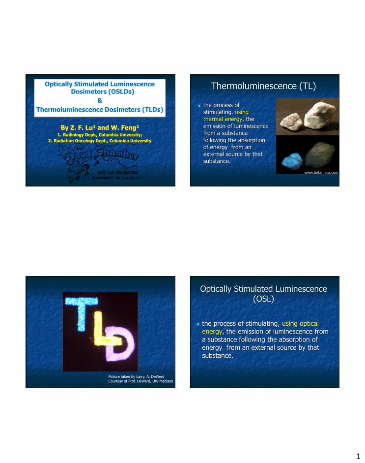
Thermoluminescence (TL)
the process of stimulating, using thermal energy, the emission of luminescence from a substance
following the absorption of energy from an external source by that substance.
www.britannica.com
Picture taken by Larry. A. DeWerdCourtesy of Prof. DeWerd, UW-Madison
Optically Stimulated Luminescence (OSL)
the process of stimulating, using optical energy, the emission of luminescence from a substance following the absorption of energy from an external source by that substance.
2
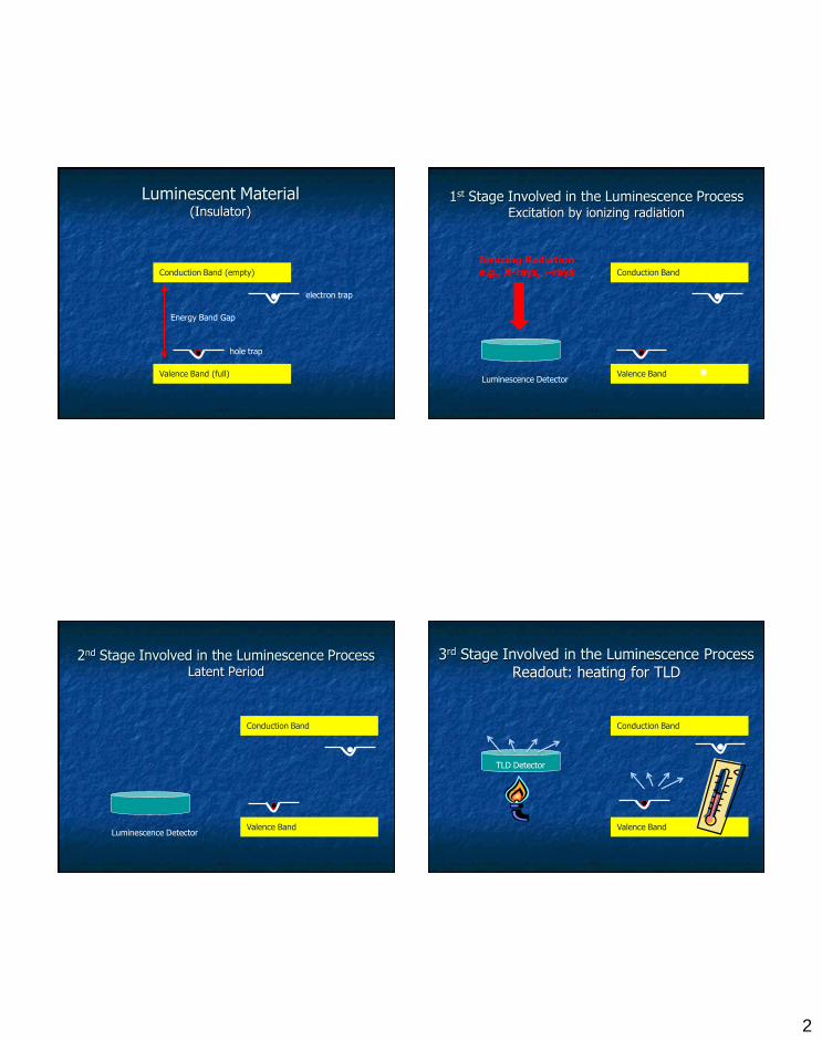
Luminescent Material(Insulator)
Valence Band (full)
Conduction Band (empty)
Energy Band Gap
electron trap
hole trap
1st Stage Involved in the Luminescence ProcessExcitation by ionizing radiation
Luminescence Detector
Ionizing Radiatione.g., X-rays, g-rays
Valence Band
Conduction Band
2nd Stage Involved in the Luminescence ProcessLatent Period
Valence Band
Conduction Band
Luminescence Detector
3rd Stage Involved in the Luminescence Process Readout: heating for TLD
TLD Detector
Valence Band
Conduction Band
3
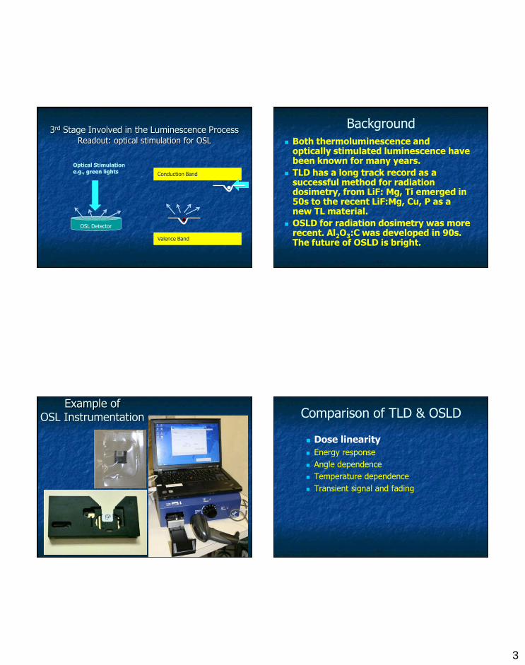
3rd Stage Involved in the Luminescence ProcessReadout: optical stimulation for OSL
OSL Detector
Valence Band
Conduction Band
Optical Stimulatione.g., green lights
Background
Both thermoluminescence and optically stimulated luminescence have been known for many years.
TLD has a long track record as a successful method for radiation dosimetry, from LiF: Mg, Ti emerged in 50s to the recent LiF:Mg, Cu, P as a new TL material.
OSLD for radiation dosimetry was more recent. Al2O3:C was developed in 90s. The future of OSLD is bright.
Example of OSL Instrumentation Comparison of TLD & OSLD
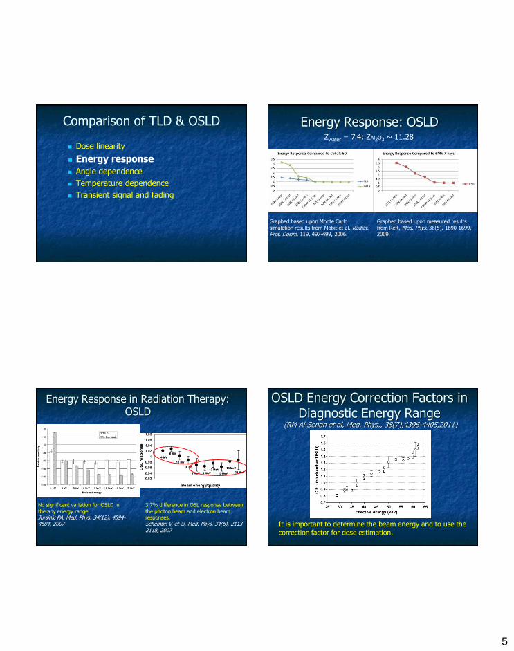
Dose linearity
Energy response
Angle dependence
Temperature dependence
Transient signal and fading
4
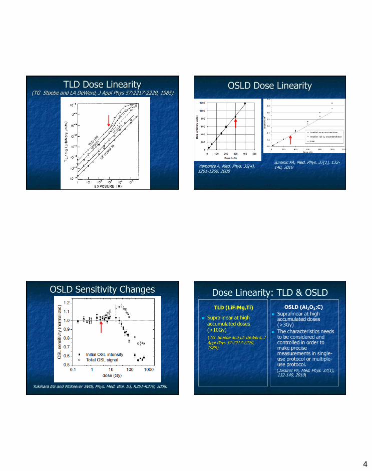
TLD Dose Linearity(TG Stoebe and LA DeWerd, J Appl Phys 57:2217-2220, 1985)
OSLD Dose Linearity
Jursinic PA, Med. Phys. 37(1), 132-140, 2010Viamonte A, Med. Phys. 35(4),
1261-1266, 2008
OSLD Sensitivity Changes
Yukihara EG and McKeever SWS, Phys. Med. Biol. 53, R351-R379, 2008.
Dose Linearity: TLD & OSLD
TLD (LiF:Mg,Ti)
Supralinear at high accumulated doses (>10Gy)
(TG Stoebe and LA DeWerd, J Appl Phys 57:2217-2220, 1985)
OSLD (Al2O3:C)
Supralinear at high accumulated doses (>3Gy)
The characteristics needs to be considered and controlled in order to make precise measurements in single-use protocol or multiple-use protocol. (Jursinic PA, Med. Phys. 37(1), 132-140, 2010)
5
Comparison of TLD & OSLD
Dose linearity
Energy response
Angle dependence
Temperature dependence
Transient signal and fading
Energy Response: OSLD
Graphed based upon Monte Carlo simulation results from Mobit et al, Radiat. Prot. Dosim. 119, 497-499, 2006.
Graphed based upon measured results from Reft, Med. Phys. 36(5), 1690-1699, 2009.
Zwater = 7.4; ZAl2O3 ~ 11.28
Energy Response in Radiation Therapy: OSLD
No significant variation for OSLD in therapy energy range.Jursinic PA, Med. Phys. 34(12), 4594-4604, 2007
3.7% difference in OSL response between the photon beam and electron beam responses.Schembri V, et al, Med. Phys. 34(6), 2113-2118, 2007
OSLD Energy Correction Factors in Diagnostic Energy Range
(RM Al-Senan et al, Med. Phys., 38(7),4396-4405,2011)
It is important to determine the beam energy and to use the correction factor for dose estimation.
6
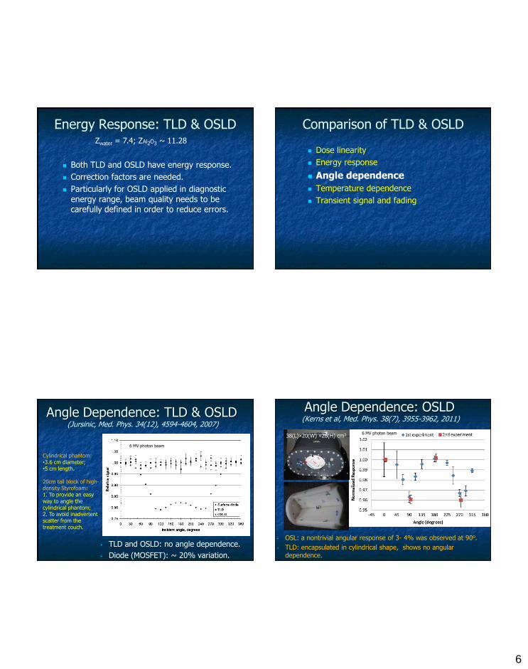
Energy Response: TLD & OSLD
Both TLD and OSLD have energy response.
Correction factors are needed.
Particularly for OSLD applied in diagnostic
energy range, beam quality needs to be carefully defined in order to reduce errors.
Zwater = 7.4; ZAl2O3 ~ 11.28
Comparison of TLD & OSLD
Dose linearity
Energy response
Angle dependence
Temperature dependence
Transient signal and fading
Angle Dependence: TLD & OSLD(Jursinic, Med. Phys. 34(12), 4594-4604, 2007)
• TLD and OSLD: no angle dependence.
• Diode (MOSFET): ~ 20% variation.
Cylindrical phantom:•3.6 cm diameter;•5 cm length.
20cm tall block of high-density Styrofoam:1. To provide an easy way to angle the cylindrical phantom;2. To avoid inadvertent scatter from the treatment couch.
6 MV photon beam
Angle Dependence: OSLD(Kerns et al, Med. Phys. 38(7), 3955-3962, 2011)
• OSL: a nontrivial angular response of 3- 4% was observed at 90o.
• TLD: encapsulated in cylindrical shape, shows no angular dependence.
6 MV photon beam38(L)×20(W) ×28(H) cm3
7
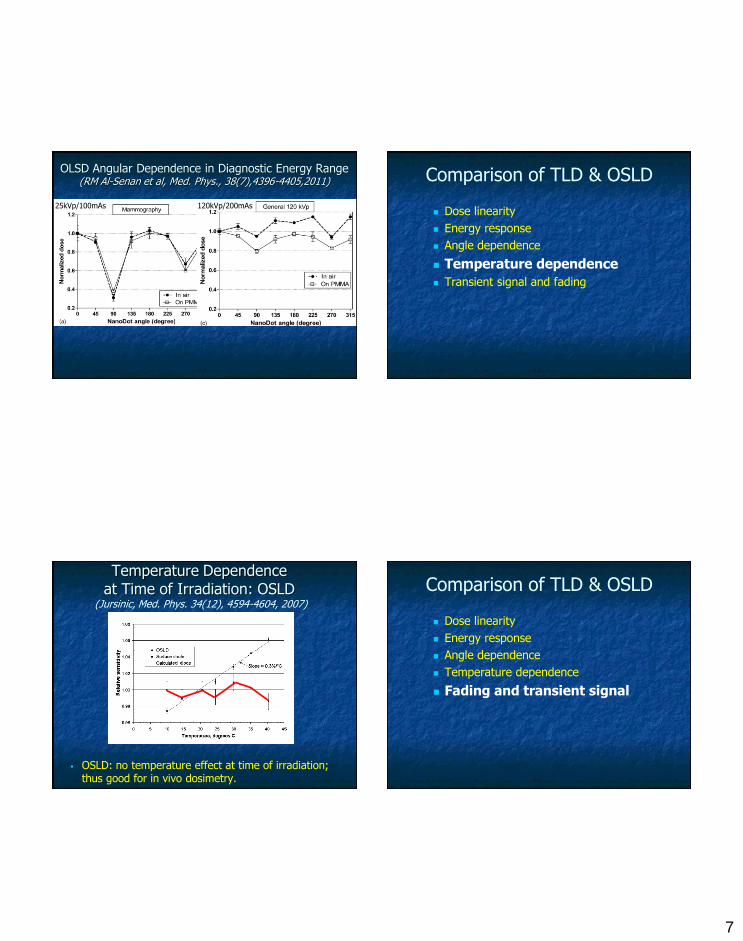
OLSD Angular Dependence in Diagnostic Energy Range (RM Al-Senan et al, Med. Phys., 38(7),4396-4405,2011)
25kVp/100mAs 120kVp/200mAs
Comparison of TLD & OSLD
Dose linearity
Energy response
Angle dependence
Temperature dependence
Transient signal and fading
Temperature Dependence at Time of Irradiation: OSLD
(Jursinic, Med. Phys. 34(12), 4594-4604, 2007)
OSLD: no temperature effect at time of irradiation; thus good for in vivo dosimetry.
Comparison of TLD & OSLD
Dose linearity
Energy response
Angle dependence
Temperature dependence
Fading and transient signal
8
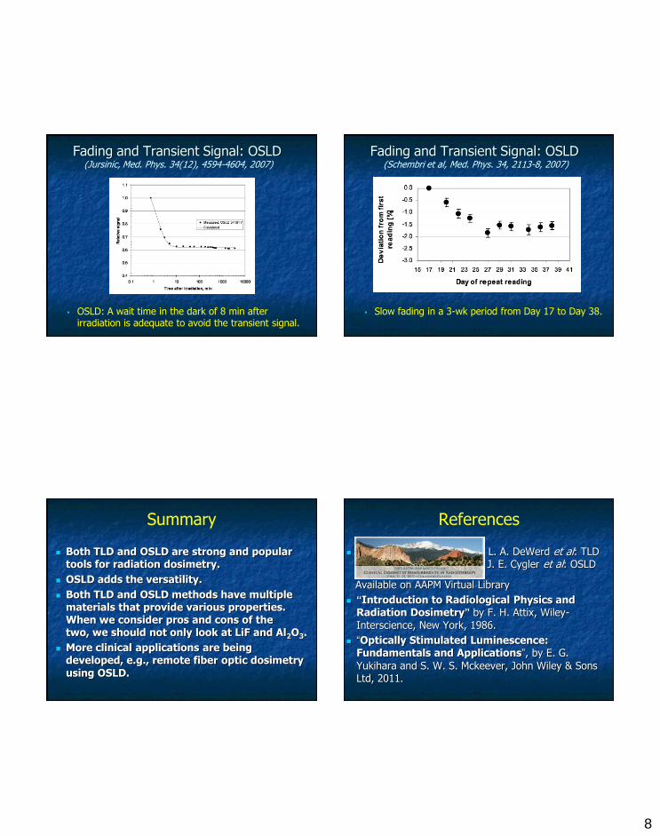
Fading and Transient Signal: OSLD(Jursinic, Med. Phys. 34(12), 4594-4604, 2007)
OSLD: A wait time in the dark of 8 min after irradiation is adequate to avoid the transient signal.
Fading and Transient Signal: OSLD(Schembri et al, Med. Phys. 34, 2113-8, 2007)
Slow fading in a 3-wk period from Day 17 to Day 38.
Summary
Both TLD and OSLD are strong and popular tools for radiation dosimetry.
OSLD adds the versatility.
Both TLD and OSLD methods have multiple materials that provide various properties. When we consider pros and cons of the two, we should not only look at LiF and Al2O3.
More clinical applications are being developed, e.g., remote fiber optic dosimetry
using OSLD.
References
2009 AAPM Summer Sc L. A. DeWerd et al: TLD TLDD J. E. Cygler et al: OSLD
Available on AAPM Virtual Library
“Introduction to Radiological Physics and Radiation Dosimetry” by F. H. Attix, Wiley-
Interscience, New York, 1986.
“Optically Stimulated Luminescence: Fundamentals and Applications”, by E. G.
Yukihara and S. W. S. Mckeever, John Wiley & Sons Ltd, 2011.
9
ANY QUESTIONS?

![Photoluminescence (PL) and Thermoluminescence (TL… · 2016-04-23 · Photoluminescence (PL) and Thermoluminescence (TL) ... dosimetry, X-ray imaging and color display [4].Various](https://static.fdocuments.net/doc/165x107/5b24c6287f8b9a10578b472a/photoluminescence-pl-and-thermoluminescence-tl-2016-04-23-photoluminescence.jpg)