IS 13883 (1993): Thermoluminescence Dosimetry systems for ...thermoluminescence dosimetry (TLD)...
57
Disclosure to Promote the Right To Information Whereas the Parliament of India has set out to provide a practical regime of right to information for citizens to secure access to information under the control of public authorities, in order to promote transparency and accountability in the working of every public authority, and whereas the attached publication of the Bureau of Indian Standards is of particular interest to the public, particularly disadvantaged communities and those engaged in the pursuit of education and knowledge, the attached public safety standard is made available to promote the timely dissemination of this information in an accurate manner to the public. इंटरनेट मानक “!ान $ एक न’ भारत का +नम-ण” Satyanarayan Gangaram Pitroda “Invent a New India Using Knowledge” “प0रा1 को छोड न’ 5 तरफ” Jawaharlal Nehru “Step Out From the Old to the New” “जान1 का अ+धकार, जी1 का अ+धकार” Mazdoor Kisan Shakti Sangathan “The Right to Information, The Right to Live” “!ान एक ऐसा खजाना > जो कभी च0राया नहB जा सकता ह ै” Bhartṛhari—Nītiśatakam “Knowledge is such a treasure which cannot be stolen” IS 13883 (1993): Thermoluminescence Dosimetry systems for personal and environmental monitoring [LITD 8: Electronic Measuring Instruments, Systems and Accessories]
Transcript of IS 13883 (1993): Thermoluminescence Dosimetry systems for ...thermoluminescence dosimetry (TLD)...

Disclosure to Promote the Right To Information
Whereas the Parliament of India has set out to provide a practical regime of right to information for citizens to secure access to information under the control of public authorities, in order to promote transparency and accountability in the working of every public authority, and whereas the attached publication of the Bureau of Indian Standards is of particular interest to the public, particularly disadvantaged communities and those engaged in the pursuit of education and knowledge, the attached public safety standard is made available to promote the timely dissemination of this information in an accurate manner to the public.
इंटरनेट मानक
“!ान $ एक न' भारत का +नम-ण”Satyanarayan Gangaram Pitroda
“Invent a New India Using Knowledge”
“प0रा1 को छोड न' 5 तरफ”Jawaharlal Nehru
“Step Out From the Old to the New”
“जान1 का अ+धकार, जी1 का अ+धकार”Mazdoor Kisan Shakti Sangathan
“The Right to Information, The Right to Live”
“!ान एक ऐसा खजाना > जो कभी च0राया नहB जा सकता है”Bhartṛhari—Nītiśatakam
“Knowledge is such a treasure which cannot be stolen”
“Invent a New India Using Knowledge”
है”ह”ह
IS 13883 (1993): Thermoluminescence Dosimetry systems forpersonal and environmental monitoring [LITD 8: ElectronicMeasuring Instruments, Systems and Accessories]


IS 13883 : 1993
tge 1066 : 1991
Indian Standard
THERMOLUMINESCENCE DOSIMETRY SYSTEMS FOR PERSONAL AND ENVIRONMENTAL
MONITORING
UDC 539’12’08 : 535’377
@ BIS 1993
BUREAU OF INDIAN STANDARDS MANAK BHAVAN, 9 BAHADUR SHAH ZAFAR MARG
NEW DELHI 110002
November 1993 Price Group 14
Nuclear Instrumentation Sectional Committee, LTD 26
NATIONAL FOREWORD
This Indian Standard which is identical with IEC 1066 : 1991, ‘Thermoluminescence dosimetry systems for personal and environmental monitoring’, issued by the International Electrotechnical Commission ( IEC ) was adopted by the Bureau of Indian Standards on the recommendation of tho Nuclear Instrumentation Sectional Committee ( LTD 26 ) and approval of the Electronics and Telecommunication Division Council.
In the adopted standard certain terminology and conventions are, however, not identical to those used in Indian Standards. Attention is particularly drawn to the following:
a) Wherever the words ‘International Standard’ appear referring to this standard, they should be read as ‘Indian Standard’.
b) Comma ( , ) has been used as a decimal marker while in Indian Standards, the current practice is to use a point ( . ) as the decimal ~marker.
Only the English language text in the international standard has been retained while adopting it in this Indian Standard.
Is 13883: 1993
IEC 1066: 1991
fndian Standard
THERMOLUMINESCENCE DOSIMETRY SYSTEMS FOR PERSONAL AND ENVIRONMENTAL
MONITORING 1 Introduction
Thermoluminescence doslmetty (TLD) systems consist essentially of the following elements:
a) a passive device, referred to here as a dosemeter, incorporating some means of identification and containing one or more detectors exhibiting the property of thermo- luminescence (TL);
b) a reader which is used for heating the detector or detectors after exposure to ionizing radiation and for measuring how much light is emitted on heating, in order to determine the radiation dose;
c) other additional equipment -and documented procedures for performing associated processes, such as annealing or cleaning, which may be needed to ensure the effective- ness of the whole system;
d) documented procedures for converting the measured light output -into dose and for handling the resulting data.
Provision is made for testing the performance of either an entire thermoluminescence dosimetry (TLD) system, dosemeters, detectors or readers tested separately. While items c) and d) are not addressed specifically, they are indirectly tested as part of the TLD system.
The performance criteria for the entire TL system are the most comprehensive been so designed that compliance ensures adequate performance of the system use in personal and environmental dosimetry consistent with the state of the art.
and have tested for
The performance criteria for detectors tested separately Include only those criteria that are clearly dependent primarily on the detector and essentially not influenced by other compo- nents needed for testing. Hence, the criteria are restricted only to~those that are meaning- ful-for a detector regardless of the remaining components used to comp!ete a system. This principle likewise applies to readers tested separately.
Some of the performance requirements specified in this standard for thermoluminescence dosimetry (TLD) systems may also be used for the design of TL dosemeters for which purpose the performance requirements for TLD systems identified in table 1, items 1 to 11 inclusive, are appropriate.
Only some specific tests may be carried out on the reader and the results are independent of the -dosemeters used. ~These points are emphasized in order to reduce the number of tests needed to qualify the system (see 8.4).
The annexes provided in this standard are considered useful for the understanding of the dosemeters and shall be taken as informative.

IS 13883: 1993
IEC 1066: 1991
Compliance with the performance criteria for dosemeters, detectors or readers tested separately does not guarantee that any system including these components will Comply with the performance criteria for thermoluminescence dosimetry (TLD) systems.
2 Scopeand object
This standard provides performance criteria and tests for determining the performance of thermoluminescence dosimetry (TLD) systems, dosemeters, detectors or readers used for personal dosimetry involving photons with energies between 15 keV and 3 MeV and beta rays with maximum energies between 05 MeV and 3,0 MeV. It does not address neutrons or mixed fields including neutrons. Where the response to neutrons is greater than 1 % of the response to photons, the manufacturer shall draw the attention of the user to this fact and where possible provide qualitative information. The quantity used in this standard for personal dosimetry is individual dose equivalent at depths of 7 or 1 000 mg - cm-*. Conver- sion tables are provided for calculating the directional dose equivalent from kerma -in air (annex A).
This standard also provides performance criteria and tests for thermoluminescence dosimetry (TLD) systems, dosemeters, detectors or readers used for environmental dosimefry involving photons with energies between 30 keV and 3 MeV. It does not specifi- cally address beta or cosmic rays. The quantity used in this standard for environmental dosimetry is ambient dose equivalent. Conversion tables are provided for calculating the ambient dose equivalent from kerma in air (annex B).
In all cases, performance is assessed under laboratory conditions which can never adequately simulate the conditions actually experienced in personal or environmental dosimetry. Therefore, caution is necessary when applying the results of these perfor- mance tests in real situations.
This standard does not incorporate requirements for extremity dosemeters or neutron dosemeters nor does it cover access to the information or handling of the resulting data.
3 Reference documents
IS0 4037: 1979, X and gamma reference radiations for calibrating dosemeters ratemeters and for determining their response as a function of photon energy.
and dose
IS0 6980: 1984, Reference beta radiations for calibrating dosemeters and doseratemeters and for determining their response as a function of beta radiation energy.
ICRU Report 33: 1980, International Commission on Radiation Units and Measurements - Radiation quantities and units.
I@fW Report 39: 1985, International Commission on Radiation Units and Measurements - Determination of dose equivalents resulting from &ternal radiation sources.
2
IS 13883: 1993
IEC 1066: 1991
4 Definitions
4.1 thermoluminescence (TL): Property exhibited by certain substances, namely the emission of light, which is induced by irradiation when the substance is heated following exposure to ionizing radiation or UV. Strictly, the property should be referred to as radio- thermoluminescence but the abbreviated form thermoluminescence is usually adequate.
4.2 thermoluminescent (TL) material: Substance exhibiting the property of thermo- luminescence.
4.3 thermdluminescent (TL) detector (abbreviation - detector): Specified quantity of TL material, or such material incorporated with other non-luminescent material into a matrix, being defined by mass, shape or size or the mass of material incorporated in the matrix.
4.4 thermoluminescent (TL) dosemeter (abbreviation - dosemeter): Passive device L
consisting of one or more TL detectors, which may be mounted in a holder (appropriate for the application), intended to be worn on a person’s body or placed in an environment for the purpose of assessing the appropriate dose equivalent at or near the position &here it is placed.
4.5 thermoluminescent (TL) dosemeter reader (abbreviation - reader): Instrument used to measure the light emitted from the detectors in thermoluminescence dosemeters, consisting essentially of a heating device, a light measuring device and the ~associated electronics.
4.6 thermoluminescence dosimetry (TLD) system (abbreviation - system): The TL dosemeter, reader and all associated equipment and procedures used for assessing the evaluated value.
4.7 environments: Areas to which members of the general public have unrestricted access.
4.8 environmental dosemeter: Dosemeter intended to be placed in the environment.
4.9 personal dosemeter: Dosemeter intended to be worn on the body.
4.10 type of system, detector or reader: Dosemeters, detectors or readers made to the same design and specification and expected to have the same properties as each other within specified limits.
4.11 batch (of detectors or dosemeters): Collection of deteetors or dosemeters made to a specific design or specification and intended to have the same performance characteristics consistent with the appropriate requirements of this standard.
4.12 annealing: Controlled thermal treatment of a TL detector or dosemeter during or after readout.
3
IS ,13883: 1993
IEC 1066: 1991
4.13 prepare: Normal treatment of annealing, cleaning, etc., which the dosemeters or detectors are intended to be subjected to in routine use.
4.14 readout: Process of measuring the light emitted when a thermoluminescence detector is heated in a reader.
4.15 readout value c Value indicated by a TL reader after readout of a detector expressed in units appropriate to the output of the reader.
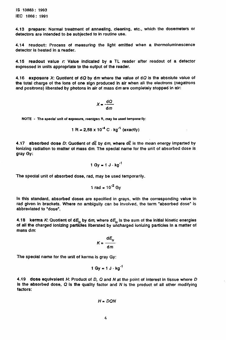
4.16 exposure X: Quotient of dC? by dm where the value of dQ is the absolute value of the total charge of the ions of one sign produced in air when all the electrons (negatrons land positrons) liberated by photons in air of mass dm are completely stopped in air:
dQ X=-
dm
NOTE - The special unit of exposure, roen$en R, may be used temporarily:
1 R = 2,58 x 10m4 C - kg-’ (exactly)
4.17 absorbed dose D: Quotient of dz by dm, where dE is the mean energy imparted by ionizing radiation to matter of mass dm. The special name for the unit of absorbed dose is gray Gy:
1 Gy = 1 -J - kg-’
-The special unit oi absorbed dose, rad, may be used temporarily.
1 rad=lO-*Gy
In this standard, absorbed doses are specified in grays, with the corresponding rad given in brackets. Where no ambiguity can be involved, the term “absorbed abbreviated to “dose”.
4.1-8 kerma K Quotient of dEt, by of all the charged ionizing particles mass dm:
value in dose” is
dm, where dEt, Is the sum of the initial kinetic energies liberated by uncharged ionizing particles in a matter of
d% K= -
dm
The special name for the unit of kerma is gray Gy:
1 Gy = 1 J . kg-’
4.19 dose equiva~lent H: Product of D, Q and Nat the point of interest in tissue where D is the -absorbed dose, Q is the quality factor and N is the product of all other modifying factors:
H= DQN
4
IS 13883: 1993
IEC 1066.: 1991
The St unit for both D and H is joule per kilogram. The special name for the unit of dose equivalent is sievert Sv:
1 Sv = 1 J - kg-’
The special unit of dose equivalent, rem, may be used temporarily:
1 rem=10~2Sv
4.20 ambient dose equlvalent W(d): Ambient dose equivalent, W(d) at a point in a radiation field, is the dose equivalent that would be produced by the corresponding aligned and expanded field (note 2) in the ICH;: sphere at a depth, d, on the radius opposing the direction of the aligned field.
NOTES
1 The recommended depth, d, for monitoring in terms of W(d) is 10 mm and H’(d) may be written as K(l0).
2 In the expanded field, the fluenoe and its angular and energy distribution have the same values throughout the volume of interest as in the actual field at the point of reference. In the aligned and expan- ded field, the fluence and Rs energy distribution are the same as in the expanded field but the fluence is unidirectional.
4.21 directional dose equivalent /f’(d): Directional dose equivalent, H’(d) at a point in a radiation field, is the dose equivalent that would be produced by the corresponding expanded field (see 4.20, note 2) in the ICRU sphere at a depth, d, on a radius in a specified direction.
NOTE - The recommended depth, d, for monitoring in terms of H(d) is 0.07 mm and H(d) may be written as H’ (0,07).
4.22 indlvldual dose equivalent, penetratlng H (d): Individual dose equivalent, penetrating, H (d), is the dose equivalent In soft tissue below a specified point on the body at a depth, d, rhat is appropriate for strongly penetrating radiation.
NOTE - The recommended depth, d, for monftorlng In terms of HP(d) is 10 mm, and H&d) may be written as H&l 0).
4.23 Individual dose equivalent, superficial H&f): Individual dose equivalent, super- ficial, H,(d), is the dose equivalent in soft tissue below a specified point on the body at a depth, d, that is approprlate for weakly penetrating radiation.
NOTE - The recommended depth, d, for monitoring in terms of H,(d) is 0.07 mm and H,(d) may~be written as H&0,07).
4.24 evaluated value E: Value of the quantity of interest (e.g. directional dose equiva- lent H’(10); air kerma Ka obtained ‘, __ app!ying the appropriate evaluation factor, Fe, to the readout value or values r).
4.25 conventlonal true value C: Best estimate of the quantity of interest at the point of measurement (e.g. directional dose equivalent H’( 10); air kerma K,).
4.26 evaluatlon factor Fe: Factor, or collection of factors, used to convert the readout value or values r to the evaluated value of interest E (see annex C).
IS 13663: 1993
lEC 1066: 1991
4.27 residue signal: Readout signal obtained on second readout following normal readout and annealing procedures.
4.28 conversion factor Fc: Factor used to convert from air kerma to the corresponding dose equivalent (see annexes A and B).
4.29 response R: Quotient of the evaluated value and the conventional true value.
4.30 self-Irradiation: Irradiation of the detector due to radioactive Impurities contained in the dosemeter ~hoider or-detector itself.
4.31 phantom: Specified object used to simulate the human body in terms of its scatte- ring and absorption of gamma and beta radiation.
4.32 zero point: Evaluated value of an unirradiated prepared dosemeter.
4.33 reader background: Evaluated value corresponding to the readout value obtained when the reader Is operated without a dosemeter or detector.
4.34 detectlon threshold: Minimum evaluated value for which the readout value of a dosemeter Is signlflcanily different (at the 95 % confidence level) from the readout value of an unirradlated dosemeter.
4.35 coefficient of variation: Ratio V of the standard deviation,
mean si; of a set of n measurements xi, given by the following formula:
I
s, to the arithmetic
4.36 routine test RT: Test performed on each TLD system, dosemeter, detector or reader to determine performance characteristics.
4.37 quality control test QT: Test performed on a number of TLD systems, dosemeters, detectors or readers of a given batch or-production designed to ensure quality control.
4.38 type test TT: Test performed on a small number of TLD systems, dosemeters, detectors or readers of a given type to determine performance characteristics of that type.
5 Untts
This standard uses SI units- For radiation quantities, the values expressed in units in temporary use (R, rad, rem) are also indicated in brackets. The following units of practical Importance will also be used where appropriate:
- for time: years (y), days (d), hours (h), minutes (min), and
f for energy: electronvolt (eV).
6
IS 13883: 1999
IEC 1066: 1991
.6
6.1
All
General test conditions
tests shall be performed under standard test conditions (table 4), except when otherwise stated. Systems, detectors and readers shall be tested in the manner in which
re expected to be used during routine personal or environmental dosimetry. For example, detectsrs shaU be subjected to the annealing, cleaning and handling procedures recommended by the
6.2 Reference radiations
All tests involving the use of Irradiated dosemeters or detectors shall be carried out using the radiation sources as specified in IS0 Standard 4037 and IS0 Standard 6980.
Photon reference radiations used for spectral response tests shall be chosen from column A of the table 1 in 3.1 of IS0 Standard 4037. Sources for beta radiation spectra response tests shall be “Sr (in equilibrium with soy) and *04TI in accordance with IS0 Standard 6980.
The calibration of the radiation sources used shall be~traceable to the appropriate primary or secondary standards.
7 Classification and designation
7.1 Classification of systems, detectors and readers
All systems, detectors and readers -are classified according to use: personal (P,) and/or environmental (En).
Systems, detectors and readers intended fied according to the dose equivalent of 1 000 mg - cm-*.
for use in personal dosimetry are further classi- interest in terms of depth in tissue, either 7 or
Systems, detectors and readers intended for use in environmental dosimetry are further classified according to the lower energy of X or gamma radiation that they are intended to measure, either 30 keV or 80 keV, and then according to the minimum period of use for which they are suited, elther seven days (7 d) or thirty days (30 d).
7.2 Designation of systems, detectors and readers
For personal dosimetry, systems, detectors and readers are designated by the following notation:
P, (dose equivalent of interest expressed as depth in tissue in mg . cm-*).
For environmental following notation:
doslmetry, systems, detectors or readers are designated by the
E, (lower energy in keV) (minimum use~period in days).
7
IS 13883 : 1993 IEC 1066 : 1991
Example Designation
TLD system intended to measure dose equivalent at 7 mg . cm” P, (7 mg . cm-*)
TLD system intended to be used for all personal and environmental dosimetry P, (all); E, (all)
TL detector intended to be used for environmental dosimetry for energies as low as 30 keV and for periods as short as 1 week E, (30 keV) (7 d)
TL reader intended to be used for personal dosimetry P, (all)
8 Performance requirements and test methods
8.1 General
Performance criteria are summarized in table 1 for TLD systems, for readers in table 2 and for detectors in table 3. Only the performance criteria pertaining to a particular class of system, reader or detector-need to be met for that class to comply with this standard.
If a detector and/or a reader.are being tested as part of a system, they do not need to be tested for the performance criteria in tables 2 and 3, only for those in table 1. If readers or detectors are being tested separately, they need only be tested for the performance criteria in table 2 or table 3, respectively. Since, in most cases, detectors are incorporated in dosemeters for practical application, there are very few quantitative performance criteria for detectors alone that are relevant, However, information on basic detector performance is necessary. The ICRU sphere (ICRU Report 33, 1980) is a tissue-equivalent sphere, 30 cm in diameter, with a density of 1 g.cm” and a mass composition of 76,2 % oxygen, 11 ,l % carbon, 10.1 % hydrogen and 2,6 % nitrogen. Therefore, compliance with this standard also requires that appropriate information be provided as indicated in table 3.
8.2 Quantities of interest and calibration
Performance criteria given in tables 1, 2 and 3 and the different tests are generally expressed in terms of the conventional true value C and of the evaluated value E. 4t is assumed that the uncertainty determining C can be neglected.
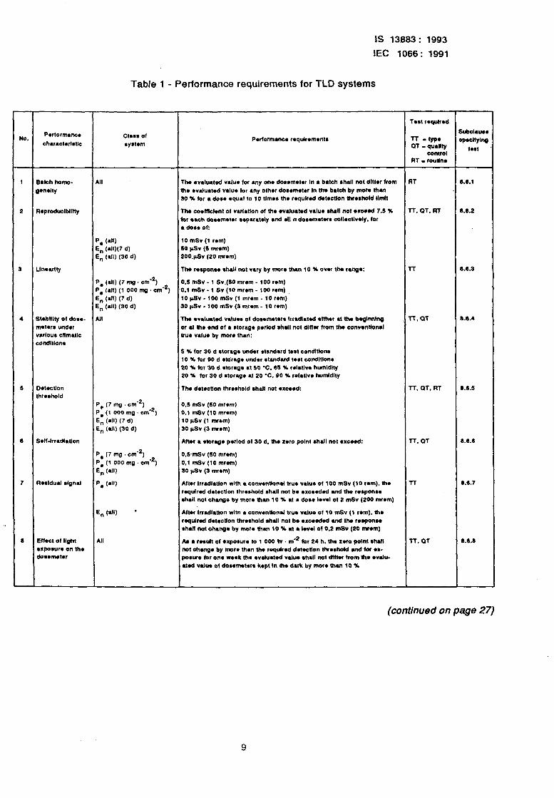
Table 1 - Performance requirements for TLD systems
1s 13883: 1993
IEC 1066: 1991
NO.
Batch homo-
J.n*lty
D~tectlon
fhr*ahold
Rwldual rlgnal
Effect 01 Aght
wtpom~~ on lhe
do~wlwtw
ill
‘. (4 in (all)(7 d)
I, (all) (30 d)
Be (all) (7 mg . cmm2)
3. (all) (1 000 mg . cme2)
En (all) (7 d)
in (atI) (30 d)
De (7 mg cmq2)
Se (1 000 mg . cmw2)
En (all) (7 d)
in (all) (30 d)
3. (7 mg Omw2)
De (1 000 mg . omq2)
En (dl)
D. (elf)
All
Pwformance r*qulr*mentr
The waluated value for any one doremoter In a batch shall not dlffw from
6w waluatad value for any other dooametw In the batch by more than
30 X for l dose equal to lo tlmor the roqulrad detectIon 6wshold Ilmtt
The co~fflclwtt of varlatlon 016~ waluatod value #hall not wc00d 7.5 X
(or each dournow rapuately and all n dosemotwr call~ctlwly. for
. do** 01:
10 mSv (1 rem)
50 pSv (5 mr*m)
2OO~pSv (20 mr*m)
The response shett not vary by mow than 10 X over the rang.:
0,s mSv - 1 Sv~(SO mrem - 100 rem)
0.1 mSv - 1 Sv (10 mrem - 100 rem)
10~Sv-lOomSv(1 mwm-lOr*m)
30 pSv - 100 mSv (3 mc*m - 10 r*m)
Th. wJua1.d val*s of dowm.t*r* Irr*dt~t.d .lth*r at ttw bogtnnlng
or al 610 end of a storage period shall not dlffw from the wnvwttbnal
true V&J* by more than:
5 X for 30 d storage undw l mdard I**1 candltlonr
10 Y for 60 d storage undw standard 1.M wndltlons
20 X tot 30 d *torage at 50 ‘C. 65 X celatlv. humid&y
20 X for 30 d rtorage at 20 ‘C. 00 X relathw humldlty
The d~twtton threshold shall not exceed:
0.5 mSv (50 mwm)
0.1 mSv (10 mwm)
10 @v (1 mrrm)
30 l&v (3 mr*m)
After l rtofage pwlod of 30 d. the zero point shall not exceed:
0.5 mSv (50 mr*m)
0.1 m.Sv (10 mrem)
30 pSv (3 mwm)
Aftw Irradlatlon with a conwnttonal two vatur of 100 mSv (10 ram). 6w
rqulred daactlon threshold shall not be wcoeded and the rerponee
ahall not change by more than 10 X at a dose Iowl of 2 mSv (200 mrem)
Aftw Irradlatlon wltn a conwntlonal true V&JO of 10 mSv (1 tom). the
rqulred deteotlon threshold shall not be wxeded and tha rorponsa
shall not thaunga by mow than 10 X at a Iwel of 0.2 m8~ (20 mWm)
k l rwu(t of l xpowf~ to 1 000 k . me2 kc 24 h. tha zero potnt shall
not churga by more than the required dawAton thwrhold md for .x-
porure for one weak the w&Wed value shall not dltlw +om the walu-
ated V&IO of dossnwtw8 kept In the dark by mow than 10 X
Tost required
TT -1YP* QT - qtmllty
control
RT I rot&t*
Al
l-f. QT. FIT
l-r
T-T, CIT
l-r. QT. R-r
TT. a1
TT
T-r. QT
1.6.1
L6.2
1.6.3
La.4
0.6.5
6.6.6
6.6.7
6.6.6
(continued on page 27)
9
IS 13883: 1993
IEC 1066: 1991
-
ua.
-
1
IO
I1
f2
13
14
15
16
17
18
-
irwrgy r.spon~. photons)
itl.lgy
.rponr. beta rays)
l mPY Pbto-)
Effect of cllmattc Yandltlons on reader
Effect Of vl-
brulon on mti.1
DroppIng l ff.ct on do*em*t*r
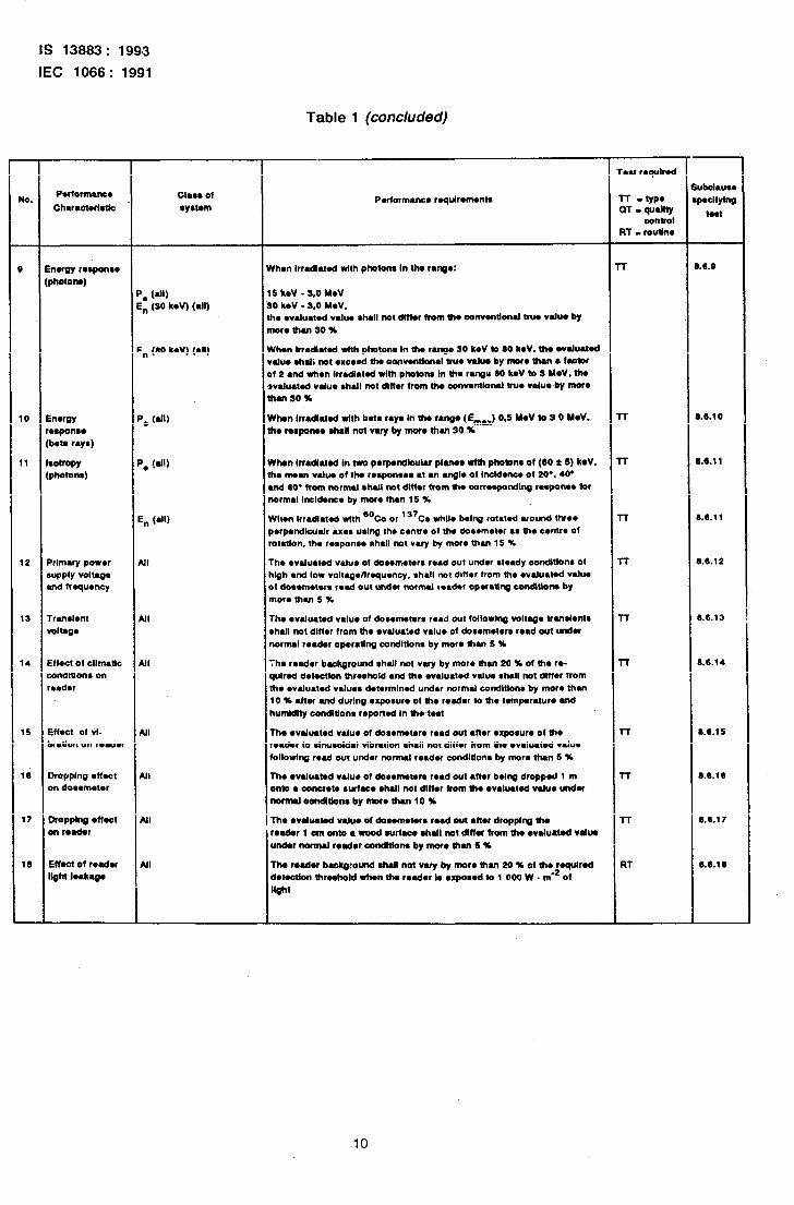
Table 1 (concluded)
CIar* of ryetom
‘. WI) L, (SO kd’) (all)
in (00 IWV) (all)
in (all)
UI
UI
UI
NI
UI
All
All
1 3
tl
n
v ”
a 3
m
Y 11
+uformam~ requlrortwnts
Yhen Irradlatod wfth photons In tha rutgo:
5 h*V - 3.0 WV 80 k*V - s.0 WV. he wduated vduo shall not differ from Uro eonventlonal from .valu* by nor. (hall so K
Uhon Inadla1.d with photon. In the r.ng. SO k.V to 80 k.V. th. l Vah#M.d ‘tiu. ohal; not .xc.ad tlw oonvwWon~l Vu. valua by~moro than l f=tOr I( 2 and wh.n Irradia1.d with photons In ho r-u 60 k*V to 5 M.V. the wluatd valu* shall not dlffw from the c0nv*mlorul ww valu*-by mow hUlSO%
Yhwt Irradiated with bata rays In the rango (E_) 0.5 WV to3 0 WV. hr ruponro shall not wry by mwo than 30 X
Yhon Inadlatad In two p~rpmdlculu plum wlfh phofonr of (60 f 6) koV. he nnan value of the reqmnses at WI angle of Imldenc~ of 20.. 40. tnd 60’ from normal shatl not dlffw from tfw con~yrondlng rwporue for tormal Incldwvx by mom than 15 X
Hl~n 1rradlat.d wfth “Co or “’ Co tille b&q rotaled around Mr.*
rqwtdkuelr .x.. using the CMIV* of the dor~m~tw . . UW CwItre Of otatlon. the r~~porw @hall not vary by more than IS X
The walualed valu. of dor.m.t.rr read out Undw steady 00ndltl0M Of rlgh and low volra~Wlrequw~cy. *hall not dlffw from the waluated valw St dowrnotws read out &or normal rvadar opnatlng oondltlonr by nor. than 5 x
rho ovahated v&re of dosometwr read Out follorln# volt-* trMrlW?tS bhall not dlffw from the walru:ed value of dosematers read out undr wormal ma&r opwaffng condltlon. by mar. thm 5 K
:he rodor background shall not vary by more then 20 % of tie re- qulred detectIon thrashold and the walualad value shall not dlffw from the waluated values detwmlnod undw normal condltlone by more then 10 X aftw and during .xposur. of Uw read., to Uw WmPwatur. and humldlty condftfons reportad In ttwtest
me walua1.d v&l* 01 dor*m*t*r* rrad out aft*, .xpoulr. of fh* r@a&r to Wwooldal dbratlon shall not dlffa from the evaluated value lollodng rod out under normal reader condltlonr by mow than 6 X
rho l valuated value of downourr read out after bvlng dropped 1 m onlo l conawt~ owfac~ shall not dlffw from ttw l valuatsd vahra under normal oandltlonr by more than 10 %
The mador bm:omd ahall not vuy by mom ban 20 X 01 UW roqufrod dofectlon fhrwhold when ti rodw IO apored to 1 000 w . me2 of
wt
l- rest rqulmd
l-l -YP* a-r - qudlty
control RT - routIn*
-r
l-r
IT
r-r
l-r
l-r
l-r
l-r
l-r
l-r
R-r
1.6.0
1.6.10
1.8.11
11.1.11
B.6.12
0.6.13
8.6.14
8.6.15
8.0.10
8.&l 7
8.6.18
10
IS 13883: 1993
IEC 1066: 1991
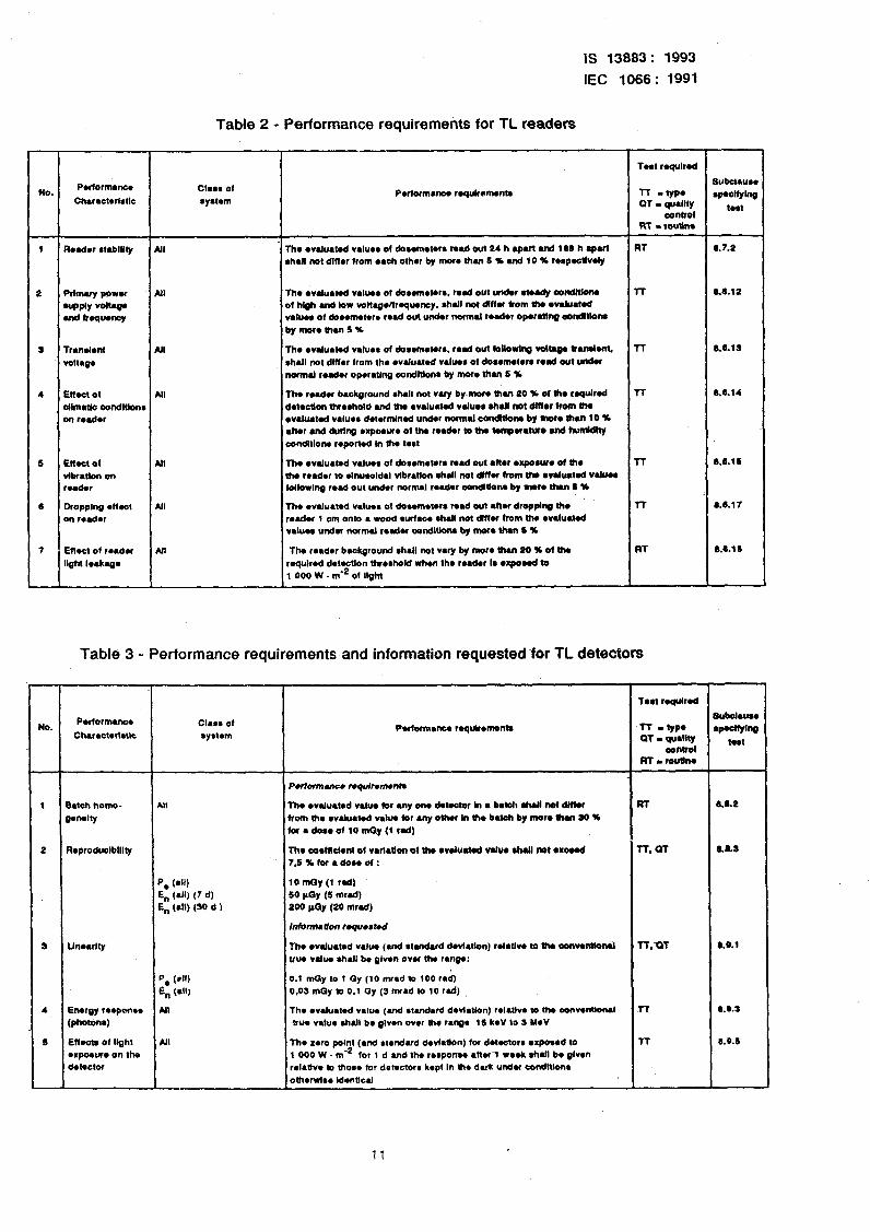
Table 2 - Performance requirements for TL readers
2 Pflnwyporw All Th. l valuawd v&8.. ot dowfn.lMr. red out und.ram&y oondlllon. 17 bO.12
upplY vowv 01 hlgh and low wltagenroquoncy. shall not dmr from thv l valuad
d f-q-w wluor of dovwnacvrv read out undw normal r*d*r opwatng aondlllons by more ha 5 Y
S Trawl*nt All The wakmtvd valuvv of dov*m*c*rr. red out rOilowing voltaga Wanalwt. m S.S.19
voRag* shall not dlffw from the l valuuvd duos of dooamemrr rod out undr normal wader opvrwlg condluonr by morv than 6 36
4 l3f.a of All Thv reader background shall not wry by-mow tian 20 % el the rqUlrOd n 6.6.14
dlmac oondltlonr de1ocUon throehold and 0~ l valua1.d vduor ahall IlOt diflor front UW on roadu waluad v~luvo dotrmlnad under normal cenMona bynwoUmnlO%
anor and during .xporu. 01 tha reador (0 tha tempnatwo and humidity condhlonv raportvd In lhv Mat
6 Eft.a of All lh. l wluatvd v&v, oi dor.nMorr mad out l ftar l xpourre d ho T-f 8.6.16
vibfubn on tha roador to slnuroldal vlbratlon ahall nol dmw horn tho l valuaWd Valuoa reador Wlowlng read out under normal roador oondlUone by mar. dun b %
0 DroppIng l flvct All Th. vvalua1ed vduva 01 dosom.t.rs read out l ttvr dropplttg the l-l LO.1 7 on r*ad*r roador 1 cm onto l wood wrfacv *hall not dffu from lho waluMed
vJun undn normal r*du oondlUon* by more then 6 %
7 Eflocl of r.adet All The reader background shall mt vary by mow than 20 % of the RT 8Alll
light leakago roqulrad de1vctlon thrvrhoid whvn thv reader IO l xpoHd to 1 000 W . mm2 01 llghr
Table 3 - Performance requirements and information requested for TL detectors
T*n roqulrvd
1 Batch honw- All The walua1ed value (or .nysrm d.tvcMr In 4 bawl ahall nol dlfhr RT e.S.2
gvn.lty front lhv vvaluatvd valm kr my other In 010 batch by more ban SO X for a do** of 10 mQy (t cad)
2 Ropcoduclblllty ma 00dw0nt of VWI~II 01 th0 l dwd vdu* 0hau not wnd TT. 01 aas
75XforadoWof:
P, (w En (all) (7 d) En (all) (SO d b
lOtiy(i tad) 50 PQy (5 mrd) 200 lay (20 nlrad)
InfomuUon requertvd
S Un*arl:y The l wluamd value (and rtandard dwlatlon) rolMlw to the oonventlonsl R.QT 8.0.1 true v&v ahall be given ovw thv range:
Pv (*II) 0.1 mQy to 1 Qy (10 mrad to 100 rad)
En (*II) 0.09 may to 0.1 oy (3 mad (0 10 fad)
4 Energy raspan** All The l valuacvd value (ti vIandard dwl~tlon) rvlatlvv 10 thv convvntk~l TT 0.8.5
(photon.) due v&m rhall bv glvw ov., hv r.ng. (5 kvV to S YvV
s Eftvola of light *II The zero point (and r~~ndu0 dwlai~n) fof detctorv wposod to l-f S.O.1 l xpoeu* on the 1 000 W . me2 for 1 d and Ihv r.rpom. l hwl rv.k shaJl be glvvn dvl*ctof rddve to thorv for dotvccorr kvp1 In O?v duk undu ~~ndltlon~
oth*rwir* ldvnucel
11
IS 13883: 1993
IEC 1066: 1991
In the case of TLD systems, table 1, the units to be used for the relevant dose equivalent quantity are Sv (rem). In the case of readers (table 2) or detectors (table 3), kerma in air expressed in gray may be used for all classes.
Where applicable, readout values shall be converted to evaluated values according to the Information and procedures given In annexes A, B and C.
All tests involving environmental TLD systems shall be performed with the dosemeter irradiated free in air. All tests for spectral response or isotropy involving personal TLD systems shall be performed with the dosemeter irradiated on a phantom (one possible phantom is the 30 cm-diameter ICRU sphere, see 8.1. Other phantoms are not excluded, provided that information be made available.)
Since the results of the remaining tests for personal dosimetry do not depend on the absence or presence of a phantom, they may be performed with or without a phantom.
8.3 Type of test required
Tests shall be performed as type tests (TT) (see 4.38). quality control tests (QT) (see 4.37), and/or routine tests (RT) (see 4.36) as indicated in tables 1, 2 and. 3. Type tests shall be carried out to establish the basic performance of a type of system, detector or reader. Quality control tests shall be carried out to verify that the performance of a specific production or delivery batch of systems, detectors or readers is consistent with that type. Routine tests shall be performed on each system, detector or reader.
8.4 Minimizing the numbers of tests
Once a system has been type-tested, any other tests to be performed on dosemeters of that system type may be performed with any reader of that system type and vice versa.
In characteristics 1, 2, 3, 4 and 8 of table 1 where the performance requirements are the same for more than one class and the detectors used are the same for these classes, then the tests need to be done for only one class.
The tests for characteristics 12, 13, 14, 15, 16 and 17 need to be done with Only one class or one type of dosemeters or detectors because the results are Independent of all compo- nents in the system other than the reader. Consequently the results are valid for all systems incorporating the same reader.
12
IS 13883: 1993
IEC 1066: 1991
a.5 Number Of dOS8m8t8rs of detectors required fof each test
The number of dosemeters or detectors used for each test, or in certain cases the number of repeated tests shall be such that th8 performance requirements are demonstrated to be met with 95 % confidence. This number may be determined from the results of a series of repsated measurements on dOSemeterS within the batch being tested (e.g. during batch homogeneity measurements) using the methods described in annex D correcting, if necessary, for fndividual sensitivities. (For tests where the test dOS8 is greater or equal to the test dose for Me Batch homogeneity test, the coefficient of variation of results from the batch homogeneity test may b8 US8d to determine n.) For tests where the coefficient of variation can be expected to be greater than that for batch homogeneity (e.g. tests with lower test doses or tests where the influence parameter may affect the coefficient of variation), it will be necessary to deternine the coefficient of variation of results for that t8St and apply an appropriate Student’s t fac:nr.
The detailed test requirements therefore include appropriate statistical criteria in general terms for n dosemeters. HOWeV8r, it may be convenient to arbitrarily use 5, 10 or 20 dose- meters or irradiations in any given test by agreement between manufacturers and purchasers. In such a case, n would b8 5, 10 or 20 and t, would -be 2,78, 2.26 or 2,09, respectively. (See annex 0, table 0.1).
8.6 Requirements and test methods for TLD systems
The different requirements and tests are expressed in terms of conventional true value C and evaluated value E where both quantities are intended to give the dose equivalent at the specified depth in tissue (as defined in ICRU Report 39) for personal dosimetty and the ambient dose equivalent (as defined in ICRU Report 39) for environmental dosimetry.
8.6.1 Batch homogeneity
8.6.1 .l Requiiements
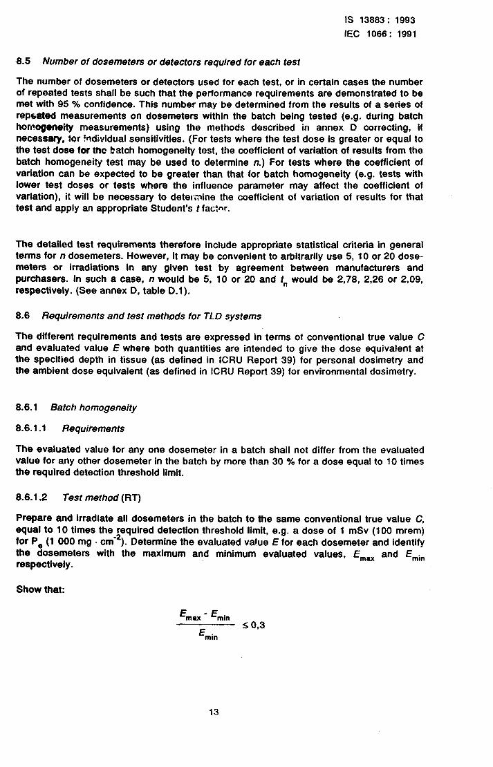
The evaluated value for any one dosemeter in a batch shall not differ from the evaluated value for any other dosemeter in the batch by more than 30 % for a dose equal to 10 times the required detection threshold limit.
8.6.1.2 Test method (RT)
Prepare and irradiate all dosemeters in the batch to th8 same conventional true value C, equal to 10 times the required detection threshold limit, e.g. a dose of 1 mSv (100 mrem) for P, (1 000 mg - cm‘*). Determine the evaluated va!ue E for each dosemeter and identify the dosemeters with the maximum and minimum evaluated values, E,,,, and Emin
respectively.
Show that:
E max _ Emin
E 54 0.3
min
13
Is 13883 : 1993
EC 1066: 1991
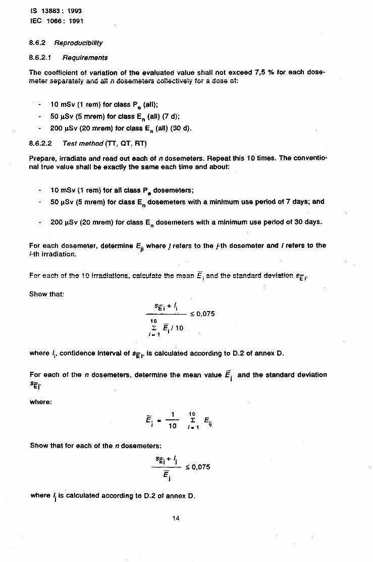
8.6.2 Reproducibility
8.6.2.1 Requirements
The coefficient of variation of the evaluated value shall not exceed 7,5 % for each dose- meter separately and all n dosemeters collectively for a dose of:
- 10 mSv (1 rem) for class P, (all);
- 50 pSv (5 mrem) for class E, (all) (7 d);
- 200 pSv (20 mrem) for class E, (all) (30 d).
8.6.2.2 Test method (lT, QT, RT)
Prepare, irradiate and read out each of n dosemeters. Repeat this 10 times. The Conventio- nal true value shall be exactly the same each time and ‘about:
- 10 mSv (1 rem) for all class P, dosemeters;
- 50 uSv (5 mrem) for class E, dosemeters with a minimum use period of 7 days; and
- 200 pSv (20 mrem) for class E, dosemeters with a minimum use period of 30 days.
For each -dosemeter, determine Eji where ] refers to the j-th dosemeter and i refers to the i-th irradiation.
~For each of the 10 irradiations’, calculate the mean Ei and the standard deviation sgi.
Show that:
sgi + ii IO,075
10 z Ei / 1~0
i= 1
where Ii, confidence interval of set, Is calculated according to 0.2 of annex D.
For each of the n dosemeters, determine the mean value gj and the standard deviation SEj.
where:
1 Ej 5: -
10
10 I; Eij
i- 1
Show that for each of the n dosemeters:
Sgi+ /j
Ej I 0,075
where /, is calculated according to D.2 of annex-D.
14
1s 13883: 1993
IEC lOii6: 1991
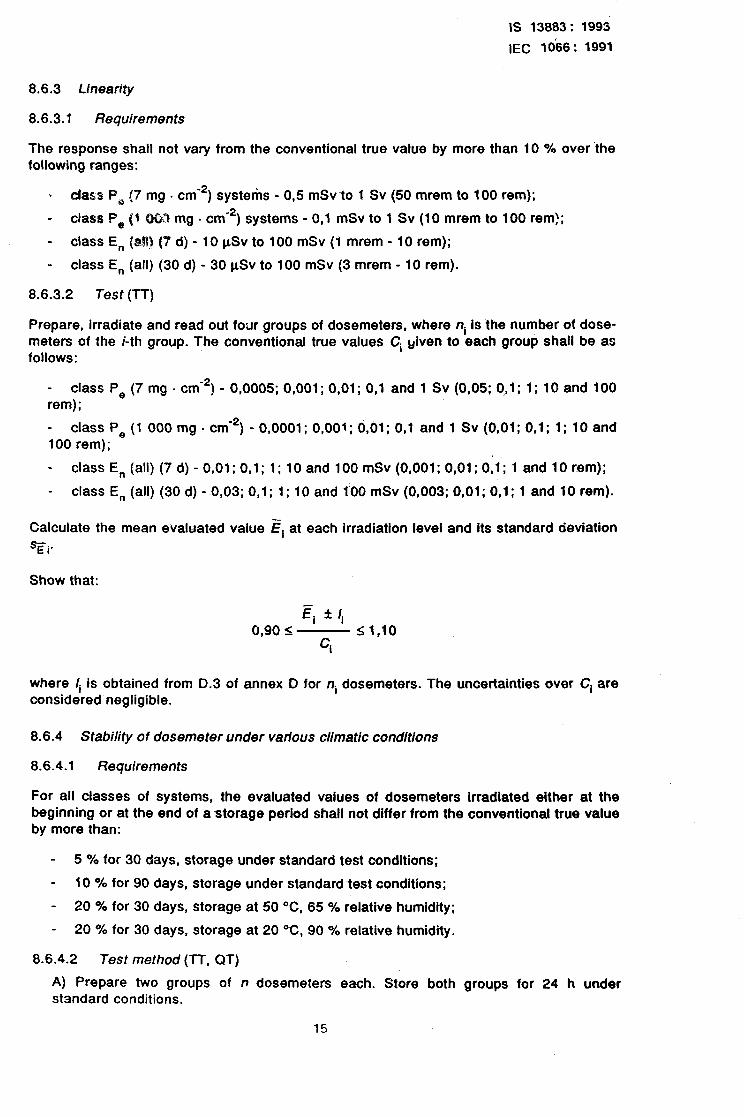
8.6.3 Linearity
8.6.3.1 Requiremsnts
The response shall nut vary from the conventional true value by more than 10 % over the following ranges:
- class P, (7 mg , cm-‘) systek - 0,5 mSvt0 1 Sv (50 mrem to 100 rem);
- class P, (I 003 mg - cm-*) systems - 0,l mSv to 1 Sv (10 mrem to 100 rem!;
- class E, (a!!) (7 d) - 10 @v to 100 mSv (I mrem - 10 rem);
- class E, (all) (30 d) - 30 pSv to 100 mSv (3 mrem - 10 rem).
8.6.3.2 Test (TT)
Prepare, irradiate and read out four groups of dosemeters, where ni is the number of dose- meters of the i-th group. The conventional true values Ci &en to each group shall be as follows:
- class P, (7 mg e cm-*) - 0,0005; 0,001; 0,Ol; 0,l and 1 Sv (0,05; O,,i; 1; 10 and 100 rem);
_ class PO (1 000 mg - cm-*) - 0,OOOl; 0,001; 0,Ol; 0,l and 1 Sv (0,Ol; 0,l; 1; 10 and 100 rem);
- class En (all) (7 d) - 0,Ol; 0,l; 1; 10 and 100 mSv (0,001; 0,Ol; 0,l; 1 and 10 rem);
- class E, (all) (30 d) --0,03; 0,l; 1; IO and
Calculate the mean evaluated value E, at each
100 mSv (0,003; 0,Ol; 0,l; 1 and 10 rem).
irradiation level and its standard deviation
Show that:
Ei *Ii
0,90 s s 1,lO ‘i
where li is obtained from D.3 of annex D for ni dosemeters. The uncertainties over Ci are considered negligible.
8.6.4 Stability of dosemeter under various climatic conditions
8.6.4.1 Requirements
For all classes of systems, the evaluated values of dosemeters irradiated either at the beginning or at the end of astorage period shall not differ from the conventional true value by more than:
- 5 % for 30 days, storage under standard test conditions;
- 10 % for 90 days, storage under standard test conditions;
- 20 % for 30 days, storage at 50 OC, 65 % relative humidity;
- 20 % for 30 days, storage at 20 “C, 90 % relative humidity.
-8.6.4.2 Test method (TT, QT)
A) Prepare two groups of n dosemeters each. Store both groups for 24 A under standard conditions.
15
IS 13883: 1993
IEC 1066: 1991
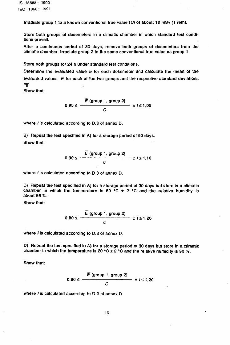
Irradiate group 1 to a known conventional true value (C) of about: 10 mSv (1 rem).
Store both groups of dosemeters in a climatic chamber in which standard test condi- tions prevail.
After a continuous period of 30 days, remove both groups of dosemeters from the climatic chamber. Irradiate group 2 to the same conventional true value as group 1.
Store both groups for 24 h under standard test conditions.
Determine the evaluated value E for each dosemeter and calculate the mean of the
evaluated values 5 for each of the two groups and the respective standard deviations
3E. Show that:
:
c (group 1, group 2) 0,95 5 f IS 1,05
c
where I is calculated according to D.3 of annex D.
Bj Repeat the test specified in A) for a storage period of 90 days.
Show that:
E (group 1, group 2) 0,90 < f /I 1,lO
C
where I is calculated according to D.3 of annex D.
C) Repeat the test specified in A) for a storage period of ~30 days but store chamber in which the temperature is 50 “C f 2 “C and the relative about 65 %.
Show that:
in a climatic humidity is
E (group 1, group 2) 0,80 5 f IzG 1,20
c
where I Is calculated according to D.3 of annex D.
D) Repeat the test specified In A) for a storage period of 30 days but store in a climatic chamber in which the temperature is 20 “C f 2 “C and the relative humidity is 90 %.
Show that:
E (group 1, group 2) 0,80 s f IS 1.20
C
where I is calculated according to 0.3 of annex D.
16
IS 13883: 1993
IEC 1066: 1991
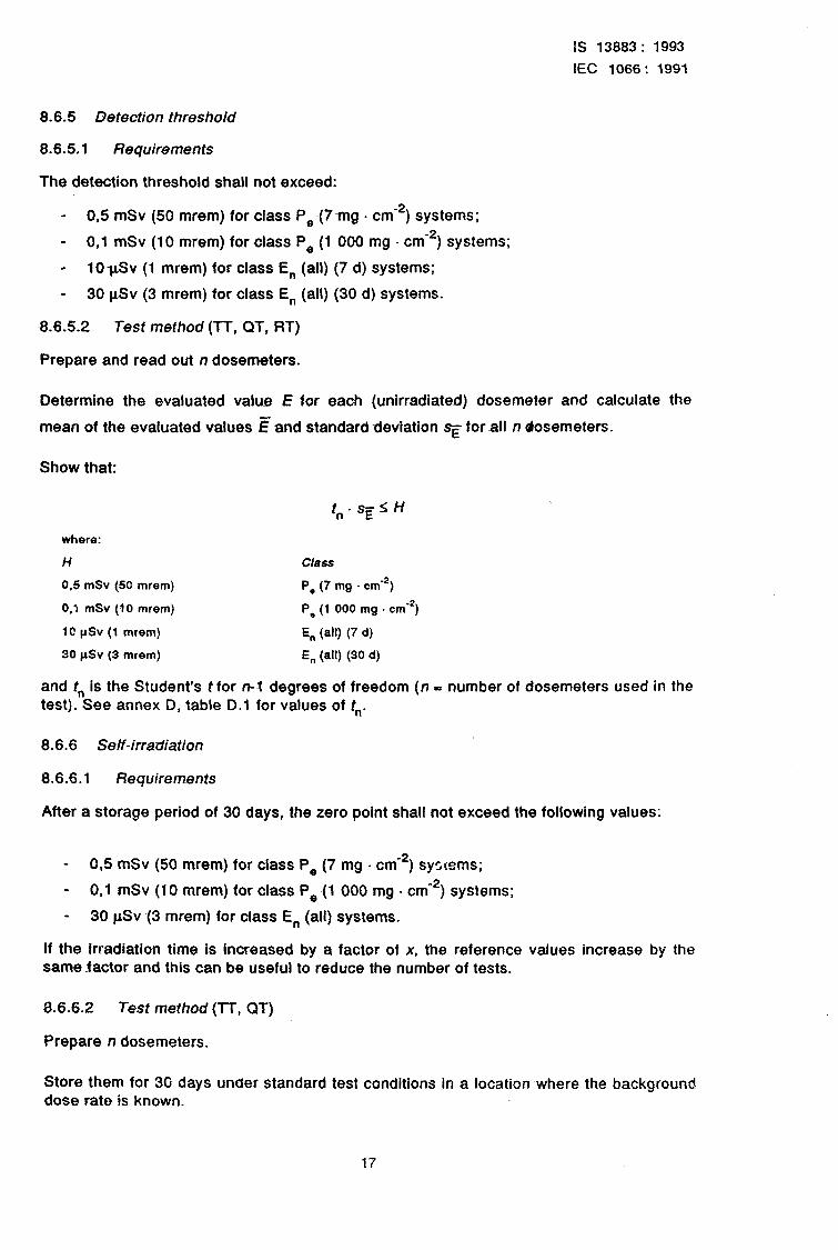
8.6.5 Detection threshold
8.6.5.1 Requirements
The detection threshold shall not exceed:
- 0,5 mSv (50 mrem) for class P,~(7mg a cmW2) systems;
- 0,l mSv (10 mrem) for-class P, (1 000 mg - cme2) systems;
- IO-pSv (1 mrem) for class E, (all) (7 d) systems;
- 30 pSv (3 mrem) for class E, (all) (30 d) systems.
8.6.5.2 Test method (IT, QT, RT)
Prepare and read out n dosemeters.
Determine the evaluated value E for each (unirradiated) dosemeter and calculate the
mean of the evaluated values I% and standard deviation q forall n dosemeters.
Show that:
where:
H
0.5 mSv (50 mrem)
0.1 mSv (10 mrem)
10 pSv (1 mrem)
30 pSv (3 mrem)
f” * sg 5 H
Ckss
P, (7 mg . cmm2)
P. (1 000 mg . cm-2)
E, (a4 (7 d)
E, (all) (30 d)
and t,, is the Student’s t for n-l degrees of freedom (n - number of dosemeters used in the test). See annex D, table D.l for values of t,,.
8.6.6 Self-irradiation
8.6.6.1 Requirements
After a storage period of 30 days, the zero point shall not exceed the following values:
- 0,5 mSv (50 mrem) for class P, (7 mg a cm-s) systems;
- 0,l mSv (10 mrem) for class P, (1 000 mg . cm-‘) systems;
- 30 pSv (3 mrem) for class E, (all) systems.
If the irradiation time is increased by a factor of x, the reference values increase by the same factor and this can be useful to reduce the number of tests.
6.6.6.2 Test method (lT, QT)
Prepare n dosemeters.
Store them for 30 days under standard test conditions in a location where the background dose rate is known.
17
IS 13883: 1993
IEC 1066: 1991
Read out the dosemeters and determine the evaluated value E.
Calculate the mean of the evaluated values E for all n dosemeters and Its standard deviation. Determine the conventional true value, C,, (background), due to the background irradiation during storage.
Show that:
(IF+/)-Ct.$H
where:
H Class
0.5 mSv (50 mrem) P, (7 mg . cm-‘)
0.1 mSv (10 mrem) P, (1 000 mg . cm-*)
30 pSv (3 mrem) E, W)
where I Is calculated according to D.3 of annex -D. The uncertainties over C,, are considered negligible.
8.6.7 Residue
8.6.7.1 Requirements
After irradiation with a conventional true value of 100 mSv (10 rem) for all class Pe systems, the required detection threshold, as specified in 8.6.5, shall not be exceeded and the response shall not change by more than 10 % at a level of 2 mSv (200 mrem).
After irradiation with a conventional true value of 10 mSv (1 rem), for all class En systems, the required detection threshold, -as specified in 8.64 shall not be exceeded and the response shall not change by more than 10 % at a level of 0,2 mSv (20 mrem).
8.6.7.2 Test method (TT)
A) Effect on detection threshold
Prepare, irradiate and read out the n dosemeters used for the detection threshold test (see 8.6.5). The conventional true value C shall be about 100 mSv (16 rem) for all class P, systems and 10 mSv (1 rem) for all class E, systems.
Using the same dosemeters, repeat the test for detection threshold (see 8.6.5).
B) Effect on response
Prepare, irradiate and read out the same n dosemeters used In A).
The conventional true value C shall be about 2 mSv (200 mrem) for all class P, sys- tems and about 0,2 mSv (20 mrem) for all class E, systems.
Determine the evaluated value E for each dosemeter and calculate the mean of the
evaluated values g and standard deviation, SE.
18

IS 13883: 1993
IEC 1088: 1991
Show that:
where I is calculated according to D.3 of annex D. Uncertainties over C are considered negligible.
NOTE I This test essentially limits any residue to a level of the order of 0.1 %.
8.6.8 Effects of light exposure on the dosemeter
8.6.8.1 Requirements
After exposure to 1 000 W . m-* (see note) for 24 h the zero point shall not change by more than the required detection threshold and after exposure for one week the evaluated value shall not differ from the evaluated value of dosemeters kept in the dark by more than 10 %.
NOTE - To produce 1 000 W . mm2 of light. use an apparatus which produces light whose spectrum correb- ponds to that of bright sunlight (295 nm to 769 nm), e.g. a xenon lamp equipped, if necessary, with appro-
priate filters, or use a daylight fluorescent lamp.
8.6.8.2 Test method (TT, QT)
A) Effect on zero point
Prepare two groups of 20 dosemeters each.
Expose group 1 to 1 000 W - m-* of light (see note to 8.6.8.1) for 24 h. (Ensure that the temperature cf the dosemeters is maintained at less than 40 “C.)
Store the group 2 dosemeters in the dark in an otherwise identical environment. (Ensure that the temperature of group 2 dosemeters Is within *:5 “C of the group 1 dose- meters.)
After one day, read out all dosemeters.
Determine the evaluated value E for each and calculate the mean of the evaluated
values g for each of the two groups and their respective standard deviations.
Show that:
[E (group 1) - if (group 2)] f I i;H
where I is calculated according to D.4 of annex D for the difference of two means,
where:
H Class
500 pSv (50 mrem) P, (7 mg . cm-*)
100 pSv (10 mrem) Pe (I 000 mg . cm-*)
10 f.rSv (1 mrem) En (all) (7 d)
30 r&v (3 mrem) En (all) (30 d)
19
IS 13883: 1993
IEC 1066: 1991
6) Effect on response. r
Prepare and irradiate two groups of 20 dosemeters each. The conventional true value C shall be about 10 mSv (1 rem) for class P, (all) and class E, (ail) systems.
Expose and store groups 1 and 2 respectively as in A).
After 168 h read out all dosemeters.
Determine the evaluated value E for each and calculate the mean of the evaluated
values (E) for each of the two groups and their respective standard deviations.
Show that:
E (group 1) 0,90 ZG _ f II 1,lO
E (group 2)
where I is calculated according to D.4 of annex D for the quotient of two means.
8.6.9 Energy response (photons)
8.6.9.1 Requirements
When irradiated with-photons in the range 15 keV to 3,0 MeV for class Pe (all) doseme- ters, and in the range 30 keV to 3,0 MeV for class En (30 keV) (all) dosemeters, the evaluated value shall not differ from the conventional true value by more than 30 %.
For class En (80 keV) (all) dosemeters, when irradiated with photons in the range 30 keV to 80 keV, the evaluated value shall not exceed the conventional true value by more than a factor of two and when irradiated with photons in the range 80 keV to 3,0 MeV, the eva- luated value shall not differ from the conventional true value by more than 30 %.
8.6.9.2 Test method (TT)
A) All personal dosemeters and environmental dosemeters class E, (30 keV) (all)
Prepare, irradiate and read out four groups of n dosemeters each. The conventional true value C for class P, (all) and for class E, (30 keV) (all) shall be about 10 mSv (1 rem), using the following raa&ion:
- group 1: 15,8 keV X-rays;
- group 2: reference radiation in range 30-40 keV;
- group 3: reference radiation in range 80-100’ keV;
- group 4: -13’Cs or “Co.
Determine the evaluated value E for each dosemeter and calculate the mean of the
evaluated values g for each of the four groups and the respective standard deviations.
For each group show that:
Ei f /i 0,7 5 < 1,3 c (i = 1) 2, 3, 4)
where I is calculated according to 0.3 of annex D. Uncertainties over C are considered negligible.
20
IS 13883: 1993
IEC 1066: 1991
NOTES
1 .Personal dosemeters should be irradiated on a phantom.
2 Group 1 energy should not be used for environmental dosemeters.
B) Environmental dosemeters, class En (80 keV) (all)
Perform the t@?sf 3.e in A) for class En (30 keV) (all).
For group 2, show that:
E+I <2 _- c -
For groups 3 and 4, show that:
Ei f Ii
0,7 1. 5 1,3 C
(i= 3, 4)
8.6.10 Energy response (beta rays)
8.6.10.1 Requirements
For class P, (all) dosemeters, when irradiated with beta rays in the range (Em,) 03 MeV to 3 MeV, the response shall not vary by more than 30 %.
8.6.10.2 Test method (TT)
Prepare, irradia?e and read out two groups of n dosemeters each. The conventional true value C shall be about 10 mSv (1 rem) using the foltowing:
- group 1: gOSrlgOY;
- group 2: 204TI.
Determine the evaluated value E for each dosemeter
evaluated values ,!! for each of the two groups.
For each group, show that:
Ei f Ii
0,7 5 C
11.3 (i=
and calculate the mean -of the
192)
8.6.11 isotropy (photons)
8c6.11.1 Requirements
For PO (all) dosemeters irradiated with photons of 60 f 5 keV, the mean value of the responses at angles of incidence of 20°, 40’ and 60” from normal shall not differ from the corresponding response for normal incidence by more than 15 %.
For En (all) dosemeters irradiated with 6oCo or 13’Cs while being rotated around three perpendicular axes using the centre of the dosemeter as the centre of rotation, the response shall not vary by more than 15 %.
21
IS 13883: 1993
IEC 1066: 1991
8.6.11.2 Test method (TT)
A) Personal dosemeters
Prepare, irradiate on a phantom and read out four groups of dosemeters. Let rti be the number of dosemeters of the i-th group. The conventional true value’c shall be about 10 mSv (1 rem) using photons of energy (60 f 5) keV (X-rays or 24’Am) and the following conditions:
- group 1: normal incidence;
- group 2: 20” off normal;
- group 3: 40° off normal;
- group 4: 60” off normal.
The angle of incidence is varied in two ~planes perpendicular to each other and to the plane of the dosemeter adjacent to the -phantom. More than one irradiation at each angle can be undertaken simultaneously on a sphered phantom.
Determine the evaluated value E for each dosemeter and calculate the mean of the
evaluated values E for each of the four groups and the respective standard deviations SE.
Show that:
4
I: Ei
0,85I j=’ 4Ei
f I< 1,15
where I is determined according to 0.4 of annex D.
6) Environmental dosemeters
Prepare, irradiate and read out three groups of n dosemeters each. The conventional true value C shall be about 10 mSv (1 rem) using 6oCo or 13’Cs. During irradiation, each dosemeter in each group shall be rotated around one of three perpendicular axes using the centre of the dosemeter as the centre of rotation.
Determine the evaluated value E for each dosemeter of each group and calculate the
mean of the evaluated values E and the respective standard deviations SE for each group.
Show that, f?r each group:
0,85 < Ei ri
- C
5 1,15 (i= 1, 2, 3)
where I is determined according to D.3 of annex D.
8.6.12 Primary power supply voltage and frequency
8.6.12.1 Requirements
For all classes, the evaluated value of dosemeters read out under steady conditions of high or low voltage/frequency shall not differ from the evaluated value of dosemeters read out under normal reader operating conditions by more than 5 %.
22
is 13883: 1993
IEC 1066: 1991
8.6.12.2 Test method (lT)
Prepare and irradiate five groups of dosemeters. Let ni be the number of dosemeters the i-th group. The conventional true value C shall be about 10 mSv (1 rem).
Read out the dosemeters under the following conditions:
- group 1: narmat reader operation;
- group 2: voltage t2 % low and frequency 2 % low;
- group 3: voltage 10 % high and frequency 2 % low;
- group 4: voltage 10 % high and !requency 2 % high;
- group 5: voltage 12 % low and frequency 2 % high.
of
Determine the evaluated value E for each dosemeter and calculate the mean of the
evaluated values E for each group and the respective standard deviations.
Show that for groups 2 to 5:
E (group x) 695 I;
E (group 1) f IS 1.05 (x = 2, 3, 4, 5)
where I is calculated in accordance with D.4 of annex D.
8.6.13 Transient volfage
8.6.13.1 Requirements
For all classes, the evaluated value of dosemeters read out following voltage transients shall not differ from the evaluated value of dosemeters read out under normal reader operating co,lditions by more than 5 %.
8.6.13.2 Test method (TT)
Prepare and irradiate three groups of n dosemeters. Let ni be the number of dosemeters of the i-th group. The conventional true value C shall be about 10 mSv (1 rem). Read out all the dosemeters in each group respectively under the following conditions:
- group 1:
- group 2: decrease to 20
- group 3:
normal reader operation;
after a transient decrease (initial voltage 10 % below nominal, 1 s % below nominal held for 1 s, return to 10 % below nominal in 2 s);
after a transient increase (initial voltage 10 % above nominal, 1 s increase to 20 % above nominal held for 1 s, return to 10 % above nominal in 2 s).
Determine the evaluated value E for each dosemeter and calculate the mean of the
evaluated values E for each group and the respective standard deviations.
23
IS 13883: 1993
IEC 1066: 1991
Show that for groups 2 and 3:
E (group x) 0.95 I; _ f 15 1,05
E (group 1) (x = 2, 3)
where I is calculated according to D.4 of annex D.
8.6.14 Effects of climatic conditions on the reader
8.6.14.1 Requirements
For all classes, the reader background shall not vary by more than 20 % of the required detection threshold and the evaluated values shall not differ from the evaluated values determined under normal conditions by more than 10 % after and during exposure of the reader to the temperature and humidity conditions reported In the test (see A) and 6) below).
8.6.14.2 Test method (lT)
A) Effects on reader background
Perform nine groups of readout cycles. Let ni be the number of cycles performed in the i-th group. Each readout cycle shall be performed without a detector or a dosemeter’ in the reader under the following conditions:
- group 1: normal reader operation;
- group 2: after reader exposure to +60 OC and 65 % RH;
- group 3: during reader exposure to +35 “C and 65 % RH;
- group 4: after reader exposure to -10 “C and 65 % RH;
- group 5: during reader exposure to +lO OC and 65 % RH;
- group 6: after reader exposure to +20 “C and 90 % RH;
- group 7: during reader exposure to +20 “Cand 90 % RH;
- group 8: after reader exposure to +20 “C and 5 % RH;
- group 9: during reader exposure to +20 OC and 5 % RH.
Determine the evaluated value E for each readout and calculate the mean of the
evaluated values c for each group and its standard deviation.
Show that for groups 2 to~9:
[E (group x) - E (group l)] f I5 0,2 x Hmax (x = 2-10 9)
where I-$,,, is the required detection threshold (see 8.6.5) for the class being tested and / is determined according to the methods of D.4 of annex D.
If the reader cannot be operated without a dosemeter or a detector, a dummy may be substituted.
24
1s 13883: 1993
IEC 1066: 199.1
B) Effects on response
Prepare and irradiate nine groups of dosemeters. Let ni be the number of dosemeters ,of the Cth group. The conventional true value C shall be about 10 mSv (1 rem).
Read out the dosemeters under the following conditions:
- group 1:
- group 2:
- group~3:
- group 4:
- group 5:
- group 6:
- group 7:
- group 8:
- group 9:
normal reader operation;
after reader exposure to +60 “C and 65 % RH;
during reader exposure to +35 “C and 65 % RH;
after reader exposure to -10 OC and 65 % RH;
during reader exposure to +lO OC and 65 % RH;
after reader exposure to +20 OC and 90 % RH;
during reader exposure to +20 “C and 90 % RH;
after reader exposure to +20 “C and 5 % RH;
during reader exposure to +20 V and 5 % RH.
Determine the evaluated value E for each readout and calculate the mean of the
evaluated values E for each group and its standard deviation.
Show that for groups 2 to 9:
E (group x) 0,90 5 _ f II 1,lO
E (group 1) (x = 2 to 9)
where I is determined according to D.4 of annex D.
NOTE - The test conditions should be achieved by using a climatic test chamber as follows:
1) For readouts after climatic exposure
TempereWe - Place the reader (without dosemeters or detectors and without power applied) in the climatic chamber under standard oonditions. Raise or lower the temperature at a rate of 215 “C.h-‘.
Maintain the required temperature for 2 h. Return the temperature at a rate of ~15 ‘C.h-’ to standard
conditions. Maintainthe reader in the chamber under standard conditions for 6 h before testing.
Humidity - Place the reader (without dosemeters or detectors and without power applied) in the climatic
chamber under the humidity conditions required for 24 h. Remove the reader and after 1 h. apply
power. Maintain the reader under standard conditions for 6 h before testing.
2) For readouts during climatic exposure
Temperature - Place the reader (with power applied) in the climatic chamber under standard test conditions. Raise or lower the temperature at a rate 215 “C.h-‘. Maintain the required temperature for 2 h. Perform the readouts in the chamber under these conditions, introducing any dosemeters just prior to readout.
HumMy - Place the reader (with power applied) in the climatic chamber under the required humidity conditions. hlamtain these conditions for 6 h. Perform the readouts in the chamber under these
condition introducing any dosemeters just prior to readout.
25
IS 13883: 1993
IEC 1066: 1991
8.6.15 Effects of vibration on the reader
8.6.15.1 Requirements
For all classes, the evaluated value of dosemeters read out following exposure of the rea- der to sinusoidal vibration shall not differ from the evaluated value following readout under normal reader conditions by more than 5 %.
8.6.15.2 Test method (TT)
Prepare and irradiate two groups each group. The conventional true
of dosemeters. Let ni be the number of dosemeters of value C shall be about 10 mSv (1 rem).
Read out the dosemeters under the following conditions_:
- group 1: normal reader operation;
- group 2: after reader exposure to vibration (see note below).
Determine the evaluated value E for each dosemeter and calculate the -mean of the
evaluated values E for each group and its standard deviation.
Show that:
E (group 2) 0,95 I
E (group 1) f 111.05
where I is determined according to D.4 of annex D.
NOTE - The test conditions should be achieved as follows: with the reader mounted in its normal
orientation, it is vibrated (displacement in the vertical direction) sinusoidally for 1 h at a frequency of 50 Hz and a peak-to-peak amplitude of 1 mm. The instrument should be mounted in such a way as to minimize
the generation of alternative modes of vibration.
8.6.16 Dropping effect on dosemeter
8.6.16.1 Requirements
For all classes, the evaluated value of concrete surface shall not differ from the than 10 %.
8.6.16.2 Test method (7-r)
dosemeters readout being dropped 1 m onto a evaluated value under normal conditions by more
Prepare and irradiate two groups of dosemeters. Let ni be the number of dosemeters of each group. The conventional true value C shall be about 10 mSv (1 rem). Read out the dosemeters under the following conditions:
- group 1: normal operation;
- group 2: after dropping the dosemeters 1 m onto a concrete surface.
Determine the evaluated value E for each dosemeter and calculate the mean of the
evaluated values E for each group and its standard deviation.
26
IS 13883: 1993
IEC lO88: 1991
Show that:
E (group 2) 0,90 I - f /I 1.10
E (group 1)
where I is determined according to 0.4 of annex D:
8.6.17 Dropping effect on reader
8.6.17.1 Requirements
For all classes, the evaluated value of dosemeters read out following dropping the reader 1 cm onto a wood surface shall not differ from the evaluated value under normal reader conditions by more than 5 %.
8.6.17.2 Test method (lT)
Prepare and irradiate two groups of dosemeters. Let ni be the number of dosemeters of each group. The conventional true value C shall be about 10 mSv (1 rem).
Read out the dosemeters under the following conditions:
- group 1: normal reader operation;
- group 2: after dropping the reader 1 cm onto a wood surface simulating possible drop during operation.
Determine the evaluated value E for each dosemeter and calculate the mean of the
evaluated values ,!? for each group and its standard deviation.
Show that:
E (group 2) 0,95 I - f /I 1,05
E (group 1)
where I is determined-according to D.4 of annex D.
8.6.18 Effects of reader light leakage
8.6.18.1 Requirements
For all classes, the reader background shall not vary by more than 20 % of the required detection threshold when the reader is exposed to 1 000 W - m-* of light.
8.6.18.2 Test method (RT)
Perform two groups of readout cycles. Let ni be the number of cycles performed in the i-th group. Each cycle shall be performed without a detector or a dosemeter in the reader under the following conditions:
- group 1: normal reader operation;
- group 2: during reader exposure to 1 000 W . m-* (over 4 x, except base) (see note of 8.6.8.1 for conditions).
27
IS 13883: 1993
IEC 1066: 1991
Determine the mean evaluated value E for each group and the respective standard deviations.
Show that:
[E (group 2) - g (group l)] f Is 02 x Hmax
where Hmax is the detection threshold for the class being tested and I is determined according to D.4 of annex D.
8.7 Requirements and test methods for TL readers
8.7.1 General
For all classes of readers, the evaluated values E and the conventional true values C may be expressed in terms of kerma in air.
Tests may be performed with either dosemeters or detectors.
The requirements and test -methods for TL readers are those given in 8.6.12 to 8.6.17.2 except 8.6.14.2.
8.7.2 Reader stability
8.7.2.1 Requirements
The evaluated values of dosemeters read out 24 h apart and 168 h apart shall not differ from each other by more than 5 %-and 10 %, respectively.
8.7.2.2 Test method (FIT)
-Prep&e and irradiate three groups of dosemeters. Let ni be the number of dosemeters of the i-th group. The conventional true value C shall be about 10 mGy (I rad) for both P, (all) and E, (all) systems.
Store all groups for two weeks under standard conditions. Read out group 1 and use the results to determine the evaluation factor F,. Read out the remaining dosemeters under the following conditions:
- group 2: 24 h after the readout of group 1;
- group 3: 168 h after the readout of group 1.
Determine the evaluated value E for each dosemeter using the evaluation factor Fe
determined with group 1, and calculate the mean of the evaluated values 5 for each group and the respective standard deviations.
28
IS 13883: 1993
IEC 1066: 1991
Show that:
E (group 2) 0‘95 5
g (group 1) f IS 1,05
g (group 3) 0,90 <
i? (group 1) f /zz 1,lO
where I is determined according to D.4 of annex D.
8.8 Requirements and test methods for TL detectors
8.8.1 General
For all classes of detectors, evaluated values E and conventional true values C may be expressed-in terms of kerma In air.
8.8.2 Batch homogeneity
8.8.2.1 Requirements
For all classes, the evaluated value for any one detector in a batch shall not differ from the evaluated value for any other detector in the batch by more than 30 % for a dose equal’to ten times the required detection threshold limit.
8.8.2.2 Test method (RT)
Prepare and irradiate all the detectors in the batch to the same conventional true value C to a dose equal to ten times the required detection threshold limit.
Determine the. evaluated value E for each detector and identify the detectors with the maximum and minimum evaluated doses.
Show that:
E max - Emin s II,3
E min
8.8.3 Reproducibility
8.8.3.1 Requirements
The coefficient of variation of the evaluated value shall not exceed 7,5 % for a dose of:
- 10 mGy (1 rad) for class P, (all);
- 50 pGy (5 mrad) for class En (all) (7 d);
- 200 pGy (20 mrad) for class En (all) (30 d).
8.8.3.2 Test method (TT, QT)
Prepare, irradiate and read out each of n detectors. Repeat this 10 times. The conven- tional true value C shall be exactly the same each time and about:
29
IS 13883: 1993
IEC 1066: 1991
- 10 mGy (1 rad) forall class P, detectors;
- 50 pGy (5 mrad)l)or class E, (7 d) detectors;
- 200 pGy(20 mrad) for class E, (30 d) detectors.
For sach detector, determine Eji where j refers to the jth detector and i to the i-th irradiation.
For each of the 10 irradiations, calculate the mean Ei and standard deviation qt.
Show that:
sgi * Ii IO,075
10
z q/10 i= 1
where /,, confidence interval of ~~~ , is calculated according to D.2 of annex D.
For each of the n detectors, determine Ej and the mean value:
10
Ej = J- x fij 10 i= 1
and the standard deviation SQ
Show that for each of the n detectors:
Tj+ ‘i I 0,075
51
where $, confidence Interval of srj , is calculated according to D.2 of annex D.
8.9 lnfornmfion requested for TL detectors
8.9.1 Linearity
The evaluated value (and standard deviation) relative to the conventional true value shall be given over the range:
- 0,l mGy to 1 Gy (0,Ol rad to 100 rad) for P, (all) classes;
- 0,03 mGy to 0,l Gy (3 mrad to 10 rad) for E, (all) classes.
8.9.2 Procedure (TT, QT)
Prepare, irradiate and read out five groups of n detectors each. The conventional true values C for groups 1; 2; 3; 4 and 5 shall be 0,l; 1; 10 and 100 mGy, and 1 Gy (0,Ol; 0,l; 1; 10 and 100 rad) for all class P, detectors, and 0,03; 0,l; 1; 10 and 100 mGy (3, 10 and 100 mrad; and 1; 10 rad) for alklass E, detectors.
30
IS 13883: 1993
IEC 1066: 1991
Calculate the mean g and standard deviation SE of the evaluated values for each group.
Information required for each group:
E (group x)
C ;/(groupx) (x=1,2,3,4,5)
8.9.3 Energy response (photons)
For all classes, the evaluated value (and standard deviation) relative to the conventional true value shall be given over the range 15 keV to 3 MeV.
8.9.4 Procedure (TT)
Prepare, irradiate and read out four value (C) shall be about 10 mGy (1 conditions:
- group 1: 15,8 keV X-rays;
- group 2: reference radiation
- group 3: reference radiation
- group 4: 13’Cs or 6oCo.
groups of n detectors each. The conventional true rad). Read out the dosemeters under the following
in the range 30 keV to 40 keV;
in the range 80 keV to 100 keV;
Determine the evaluated value E for each detector and calculate deviation F of the evaluated values for each of the four groups.
Information required for each group:
E (group x)
the mean E and standard
C ;/(groupx) (x=1,2,3,4)
NOTES
1 All irradiations should be free in air; for “‘Cs and “Co, additional provision should be made for electron equilibrium.
2 Group 1 energy should not be used for detectors intended to be used as environmental dosemeters.
8.9.5 Effects of tight exposure on the detector
For all classes, the zero point (and standard deviation) for detectors exposed to 1 000 _W - rnw2 for one day and the response after one week shall be given relative to thosn for detectors kept in the dark under conditions otherwise identical.
8.9.6 Procedure (TT)
8.9.6.1 Effect on zero point
Prepare two groups of 20 detectors each.
‘Expose group 1 to 1 000 W - mS2 of light (see note to 8.6.8.1) for 24 h (ensure that the temperature of detectors is maintained at less than 40 OC).
31
IS 13883: 1993
IEC 1066: 1991
Store the group 2 detectors in the dark in an otherwise identical environment (the tempera- ture of group 2 detectors shalt be within f5 OC of the group 1 detectors).
After one day, read out all detectors.
Determine the evaluated value E for each and calculate the meah E and standard deviation q of the evaluated doses for each of the two groups.
Information required:
(group 1) - E (group 2); I (group 1); I (group2)
8.9.6.2 Effect on response
Prepare and irradiate two groups of 20 detectors each.
The conventional true value C shall be about 10 mGy (1 rad).
Expose and store groups 1 and 2, respectively, as in 8.9.6.1.
After one week, read out all detectors.
Determine the evaluated value E for each and calculate the mean E and standard deviation SE of the evaluated values for each of the two groups.
Information required:
I!! (group 1) / F (group 2); I (group 1); I (group 2).
9 Certification
TLD systems, detectors, and readers tested for compliance with this standard as specified in clause 8 .shatl be accompanied by a certificate which shall contain the following infor- mation:
a) manufacturer’s name and address;
b) name and address of facility at which tests were performed;
c) date on which tests were performed;
d) type, serial or identification number and description of each component tested or used for testing;
e) description of additional equipment and -procedures (including correction procedures and conversion factors) used during testing (see 1 to 7 and annex C);
f) class (or classes) tested;
g) statement indicating the results of the performance tests and, in the case of detectors tested separately, providing the information required In table 3.
32
IS 13883 : 1993 IEC 1066 : 1991
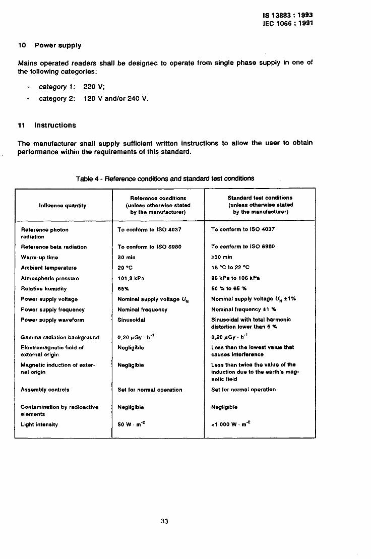
10 Power supply
Mains operated readers shall be designed to operate from single phase supply in one Of the following categories:
- category 1: 220 V;
- category 2: 120 V and/or 240 V.
11 Instructions
The manufacturer shall supply sufficient written instructions to allow the user to obtain performance within the requirements of this standard.
Table 4 - Reference conditions and standard test conditions
Influence quantity
Reference photon radiation
Reference beta radiation
Warm-up time
Ambient temperature
Atmospheric pressure
Relative humidity
Power supply voltage
Power supply frequency
Power supply waveform
Gamma radiation background
Electromagnetic field of
external origin
Magnetic induction of exter- nal origin
Assembly controls
Contamination by radioactive
elements
Light intensity
Reference conditions
(unless otherwise stated by the manufacturer)
To conform to ISO 4037
To conform to IS0 6980
30 min
20 “C
101.3 kPa
65%
Nominal supply voltage U,,
Nominal frequency
Sinusoidal
0.20 pGy . h-’
Negligible
Negligible
Set for normal operation
Negligible
50 W . m-*
Standard test conditions
(unless otherwise stated by the manufacturer)
To conform to IS0 4037
To conform to IS0 6980
230 min
18°Cto220C
86 kPa to 106 kPa
50 % to 65 %
Nominal supply voltage U,, fl%
Nominal frequency fl %
Sinusoidal with total harmonic
distortion lower than 5 $6
0.20 pGy . h-’
Less than the lowest value that
causes interference
Less than twice the value of the
induction due to the earth’s mag-
netic field
Set for normal operation
Negligible
<l 000 W. mm2
33
IS 13883: 1993
IEC 1066: 1991
Annex A
Bose equivalent conversion factors for personal dosemeters
Personal dosemeters should be calibrated in terms of dose equivalent in tissue:
_ at a depth of 7 mg - cmm2;
- at a depth of 1 000 mg - cme2.
For calibration, the dosemeters should be irradiated on a phantom at various photon energies between 15 keV and 3 MeV. The evaluated value E, for each class of systems and for each photon energy chosen,~shall be compared with the conventional true value C fin the phantom at the appropriate depth.
When the photon source is calibrated in terms of kerma in air Ka at electronic equilibrium without a receptor and the dosemeters are irradiated with phantom backing, then:
c (7 mg - cmm2) P F, ~(7 mg . cmm2) . K,
C (1 000 mg - cmw2) P Fc (1 000 mg - cmm2) . ,K,
where Fc (7 mg - cme2) and Fc (1 000 mg . cma2) are the conversion factors for the two depths. Numerical values for the conversion factors for the two classes of personal dosemeters (7 mg - cmm2 and 1 000 mg - cmm2, respectively), for one possible phantom (30 cm diameter ICRU sphere), for parallel beam geometry and for various angles of incidence are given in tables A. 1 to A. 12. Intermediate values can be obtained by interpoia- tion. These tables are-only examples of the conversion factors that are available.
Until relevant international bodies pub&h recommendations on the conversion factors to be used, the proposed examples taken from various publications may be used by agreement between the parties using the standard.
NOTE - Other phantoms are not excluded, provided that relevant information is made available.
34
IS 13883: 1993
IEC 1066: 1991
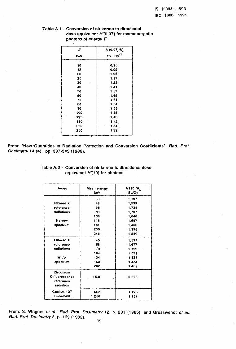
Table A. 1 - Conversion of air kerma to directional dose equivalent H’(0,07) for monoenergetic photons of energy E
E
keV
H’(O.O7)lK*
sv . q-l
10 0.95
15 0,ss
20 1,05
25 1,13
30 1.22
40 1.41
50 1.53 80 1.59
70 1,81
80 1.81
so 1,58
100 1,55
125 1,48
150 1.42
200 1.34
250 1.32
From: “New Quantities in Radiation Protection and Conversion Coefficients”, Rad. Prof. Dosimetry 14 (4) pp. 337-343 (1986).
Table A.2 - Conversion of air kerma to directional dose equivalent H’( 10) for photons
Series
Filtered X
reference
radiations
Narrow
spectrum
Filtered X
reference radiations
Wide
spectrum
Zirconium
K-fluorescence referen& radiation
Mean energy H’(lO)lKs
keV SvlGy
33 1,197
48 1,599
65 1.734
63 1,707
100 1,648
118 1,537
181 1,488
205 1,395
243 1,349
45 1.537
58 1,877
79 1,709
104 1,832
134 1.536
169 1,454
202 1,402
15.6 0,385
Cesium-137 682 1.198
Cobalt-80 1 250 1,151
~From: S. Wagner et al.: Rad. Prot. Dosimetry 12, p. 231 (1985), and Grosswendt et al.: Rad. Prot. Dosimetry 3, p. 169 (1982).
35
IS 13883: 1993
IEC 1066: 1991
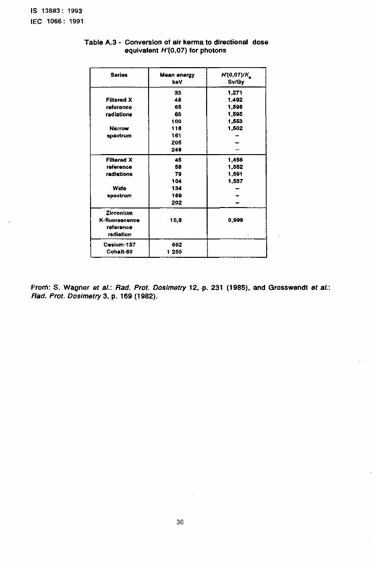
Table A.3 - Conversion of air kema to directional dose equivalent H’(0,07) for photons
Series
Filtered X
reference
radiations
Narrow
spectrum
Mean energy
keV
33
48
85
83
100 118
181
205 248
H’(O.O7)/K,
~Sv/Gy
1,271
1,492
1,598
1,595
1353 1.502
Filtered X 45 1,458
reference 58 1,552 radiations 79 1,591
104 1,537
Wide 134 8pectrum 189
202
Zirconium K-fluorescence
reference radiation
15,8 0,999
Cesium-137 882 Cobalt-80 1 250
FronI: S. Wagner et al.: Rad. Pmt. Dosimetry 12, -p. 231 (1985), and Grosswendt et al:: Rad. Pmt. Dosimetry 3, p. 169 (1982).
36
IS 13883: 1993
IEC 1066: 1991
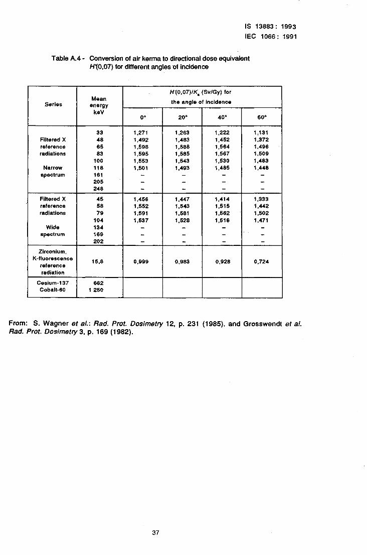
Table A.4 - Conversion of air kerma to directional dose equivalent H’(0,07) for diierent angles of incidence
Series
Filtered X
reference radiations
Narrow
spectrum
Filtered X reference
radiations
Wide spectrum
Zirconium, K-fluorescence
reference
radiation
Cesium-137 662 Cobalt-60 1 250
Mean energy
keV
33
48
65 83
100
116
161 205 248
H’(0,07)/K, (Sv/Gy) for
the angle of Incidence b
I 0" I 2o” I
40” I
60°
1,271 1,263 1,222
1,492 1,483 1,452
1,598 1,588 1,564
1,595 1,585 1,567
1,553 1,543 1,530
1.501 1,493 1,405
1,131
1,372 1,496 1,509
1,403
1,448
45 58
79
104
134 169
202
1,456 1,447 1,414 1,333
1,552 1,543 1,515 1,442
1;591 1,581 1,562 1,502
1,537 1,528 1,516 1,471
15.8
I
0,999
I
0.983
I
0,928
I
0,724
From: S. Wagner et al.: Rack Pmt. Dosimetry 12, p. 231 (1985), and Grosswendt et al. Rad. Prof. Dosimetry 3, p. 169 (1982).
37
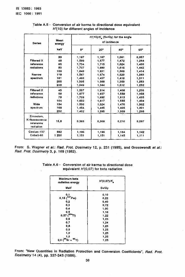
IS 13883: 1993
tEC 1066: 1991
Table A.5 - Conversion of air kerma to directional dose equivalent H’( 10) for different angles of incidence
Series Mean
energy
H’( 10)/K, (SvlGy) for the angle
of incidence
keV 0” 2o” 40° 60”
33 1,197 1.167 1,061 0.857
Filtered X 48 1,599 1,577 1,472 1,264
reference 65 1,734 1,715 1,624 1,430
radiations 83 1,707 1,690 1,616 1,442
100 1,646 1,631 1,569 1,414
Narrow 118 1,587 1,574 1,520 1,383
spectrum 161 1,466 1,457 1,416 1,311
205 1,395 1,388 1,353 1,263
248 1,349 1,344 1,312 1,232
Filtered X 45 1,537 1,514 1,408 1,200
reference 58 1,677 1,657 1,559 1,358
radiations 79 1,709 1,692 1,613 1,435
104 1,632 1,617 1,555 1,404
Wide 134 I ;536 1,524 1,476 1,352
spectrum 169 1,454 1,445 1,405 1.301
202 1,402 1,395 1,359 1,268
-Zirconium, K-fluorescence
reterence 15.8 0.365 0,309 0.210 0,097
radiation
Cesium-137 662 1.196 1,196 1,164 1.142
Cobalt-60 1 250 1,151 1,151 1,145 1,111
From: S. Wagner et al.: Rad. Prot. Dosimetry 12, p. 231 (1985), and Grosswendt el al.: Bad. Prof. Dosimetry 3, p. 169 (1982).
Table A.6 - Conversion of air kerma to directional dose equivalent H’(O,D7) for beta radiation
Maximum beta
radiation energy
MeV
091 0,15 (“‘Pm)
Q,2 0,3 0,4
0.570$TI) 0,6
0.7
908
9,9 1 ,O
1,5
2.0 jO”Sr + O”Y)
H’(0,07)IK,
SvlGy
0.10
0,22 0,40 0.72 1 ,oo
1,16 1,22 1.23
‘1.24 1,25
1,25 1.25
1.25
1,25
From: “New Quantities In Radiation Protection and Conversion Coefficients”, Rad, Prot. Dosimetry 14 (4), pp. 337-343 (1986).
38
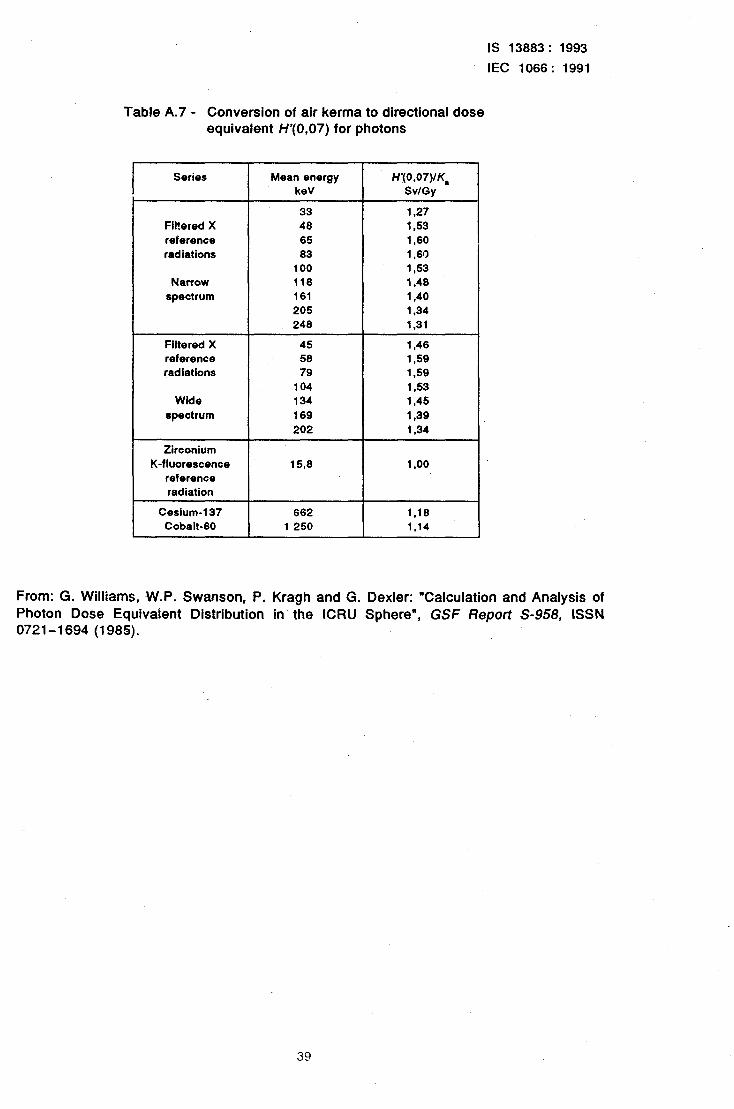
IS 13883: 1993
IEC 1066: 1991
Table A.7 - Conversion of air kerma to directional dose equivalent H’(0,07) for photons
Series
Filtered X
reference radiations
Narrow
spectrum
Filtered X
reference
radiations
Wide
spectrum
Zirconium
K-fluorescence
reference
radiation
Mean energy H’(O.O7)IK,
keV SvlGy
33 1.27
48 1,53
65 1,60
83 1,60
100 1,53
118 1.48
161 1.40
205 1,34
248 1.31
45 1,46
58 1,59
79 1,59
104 1.53
134 1,45
169 1,39
202 1,34
15,8 1 .oo
Cesium-137 662 1,18
Cobalt-60 1 250 1,14
From: G. Williams, W.P. Swanson, P. Kragh and G. Dexler: “Calculation and Analysis of Photon Dose Equivalent Distribution in the ICRU Sphere”, GSF Report S-958, ISSN 0721-1694 (1985).
39
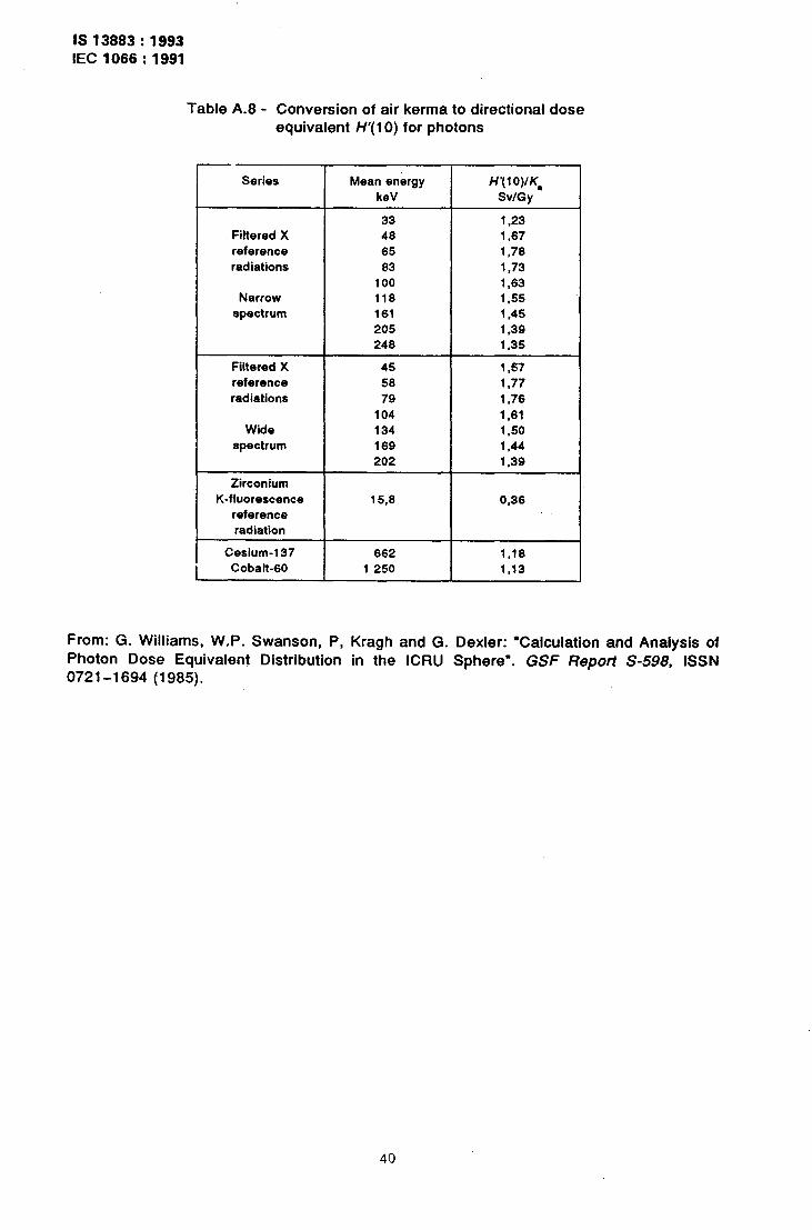
IS 13883 : 1993 IEC 1066:1991
Table A.8 - Conversion of air kerma to directional dose equivalent H’( 10) for ph Itons
Series
33 1.23 Filtered X 48 1,67 reference 65 1,78
radiations 83 1.73
1DO 1.63
Narrow 118 1,55
spectrum 161 1.45
205 1.39 248 1.35
Filtered X 45 1.57
reference 58 1,77
radiations 79 1.76
104 1,61 Wide 134 1.50
spectrum 169 1,44
202 1.39
Zirconium
K-fluorescence
reference
radiation
15,s 0.36
Cesium-137
I 662
Cobalt-60 1 259
H’(lO)IK,
SvlGy
1,18 1,13
From: G. Williams, W.P. Swanson, P, Kragh and 0. Dexler: “Calculation and Analysis of Photon Dose Equivalenj Distribution in the ICRU Sphere”. GSF Report S-598, ISSN 0721-l-694 (1985).
40
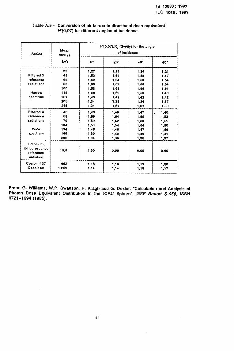
IS 13883: 1993
IEC 1066: 1991
-
-
K-!
-
C
Table A.9 - Conversion of ciir kerma to directional dose equivalent H’(0,07) for different angles of incidence
Series Mean
energy
H’(0,07)/!$ (Sv/Gy) for the angle
of incidence
keV O0 2o” 40° 60=’
Filtered X reference
radiations
Narrow
spectrum
Filtered X reference
radiations
Wide
spectrum
Zirconium,
fluorescence reference
radiation
33 1.27 1.28 1.26 -1.21
48 1,53 1.56 1.53 1,47
65 1,60 1.64 1,60 1954
83 1,60 1.62 -1.60 1.54
100 1.53 1,56 1,55 1,51
118 1.48 1,50 1.50 1.48
181 1.40 1.41 1.42 1.42
205 1.34 1.35 1.36 1,37
248 1.31 1.31 1.31 1,33
45 1,46 1,49 1.47 . 1.40
58 1.59 1,64 f .59 1.53 79 1 ,SQ 1,62 1.60 1.55
104 1,53 1,54 1.54 1,50
134 1.45 1,46 1.47 1,46
169 1,39 1 ,a0 1.40 1,41
202 1,34 1,36 1.36 1,37
15,8 1 ,oo 0,QQ 0,QQ 0.99
:esium-137 662 1,18 1,18 1.19 1,20
Cobalt-60 1 250 1,14 1,14 1.15 1.17
From: G. Williams, W.P. Swanson, P. Kragh and G. Dexler: “Calculation and Analysis of Photon Dose Equivalent Distribution in the ICRU Sphere”, GSF Report S-958, ISSN 0721-1694 (1965).
41
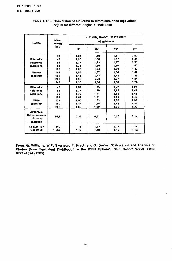
IS 13883: 1993 IEC 1066: 1991
Table A.10 - Conversion of air kerma to directional dose equivalsnt H’(10) for different angles of incidence
Series Mean
energy keV
0”
H’(lO)/K, (Sv/Gy) for the angle
of incidence
20° 40” 60”
Filtered X reference radiations
Narrow spectrum
Filtered X reference radiations
Wide spectrum
Zirconium K-fluorescence reference
radiation
33 1,23 1,19 1.11 0,97 48 1,67 1.66 1,57 1.40 65 1.76 1.73 1,67 1,50 63 1,73 1,69 1,66 1.50
100 1,63 1.64 1,60 1,47 118 155 1,57 154 1.42 161 1,45 1.47 1.44 1,35 205 1,39 1.36 1.37 1,31 248 1,35 1,34 1 ,a3 1.28
45 1.57 1.55 1,47 1,29 58 1,77 1,75 1.65 1,49 79 1.76 1,71 1.68 1.51
104 1,6l 1,61 1.59 1,45 134 1,50 1.53 150 1.39 189 1.44 1.45 1,42 1,34 202 1.39 1.39 1.38 1.32
15.8 0,36 0,31 0.25 O,l4
Cesium-137 862 1.18 1,16 1.17 1,16 Cobalt-60 1 250 1,13 1.13 1,13 1.12
From: G. Williams, W.P. Swanson, P. Kragh and G. Dexler: “Calculation and Analysis of Photon Dose Equivalent Distribution in the ICRU Sphere”, GSF Report S-958, ISSN 0721-l 694 (1985).
42
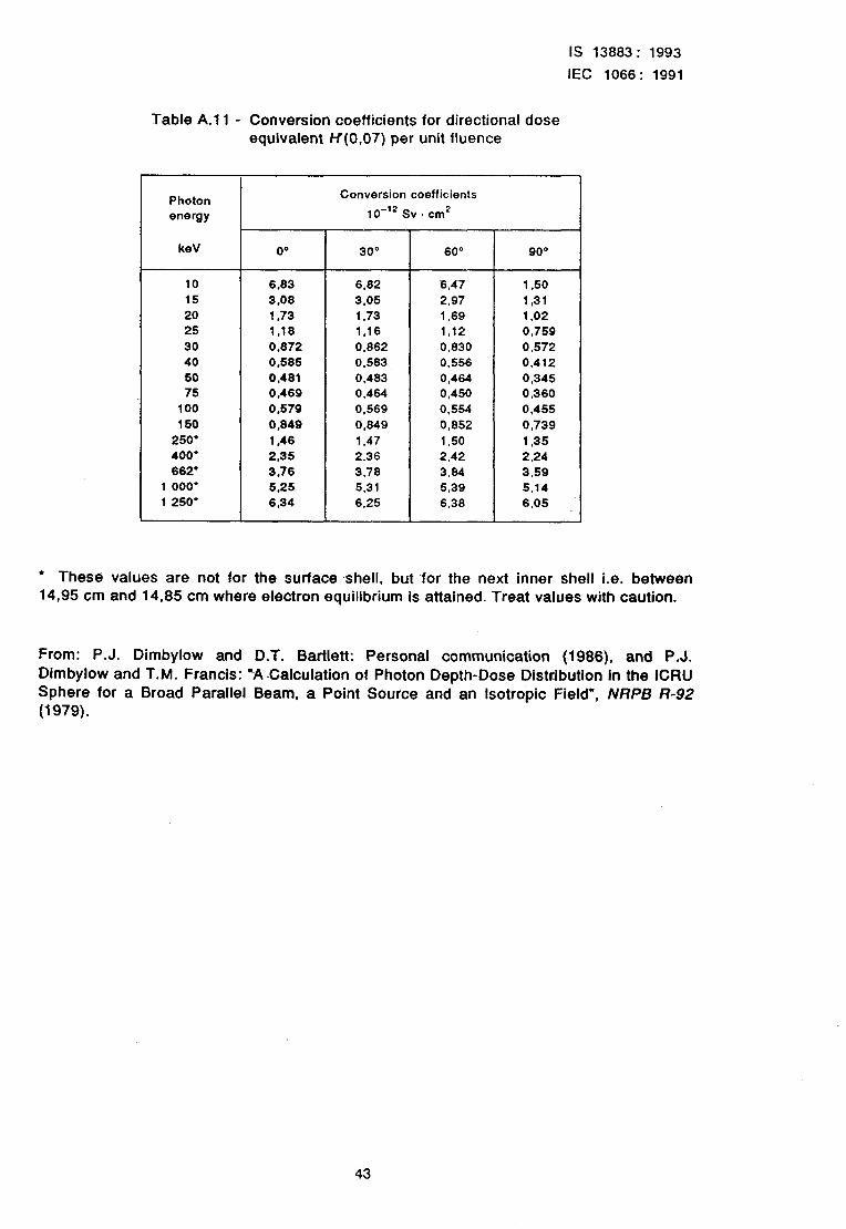
IS 13883: 1993
IEC 1066: 1991
Table A.1 1 - Conversion coefficients for directional dose equivalent H(0,07) per unit lluence
Photon energy
Conversion coefficients
10-'2Sv~cm2
k9V 00 30° 60' 9o"
10 6,63 6,82 6.47 1.50
15 3,08 3.05 2.97 1,31
20 1,73 1.73 1.69 1.02
25 1,lS 1,16 1,12 0,759
30 0,872 0,862 0,830 0.572
40 0,585 0.583 0.556 0.412
50 0,481 0,483 0,464 0,345 75 0,469 0.464 0,450 0,360
100 0,579 0.569 0.554 0.455
150 0,849 0,849 0,852 0,739
250' 1,46 1.47 1.50 1,35
400' 2.35 2,36 2.42 2.24
662' 3.76 3.78 3.84 3.59
1000' 5,25 5.31 5,39 5.14
1 250' 6,34 6.25 6.38 6,05
l These values are not for the surface shell, but -for the next inner shell i.e. between 14,95 cm and 14,85 cm where electron equilibrium is attained. Treat values with caution.
From: P.J. Dimbylow and D.T. Bartlett: Personal communication (1986), and P.J. Dimbylow and T.M. Francis: XCalculation of Photon Depth-Dose Distribution In the ICRU Sphere for a Broad Parallel Beam, a Point Source and an Isotropic Field”, NRPB R-92 (1979).
43
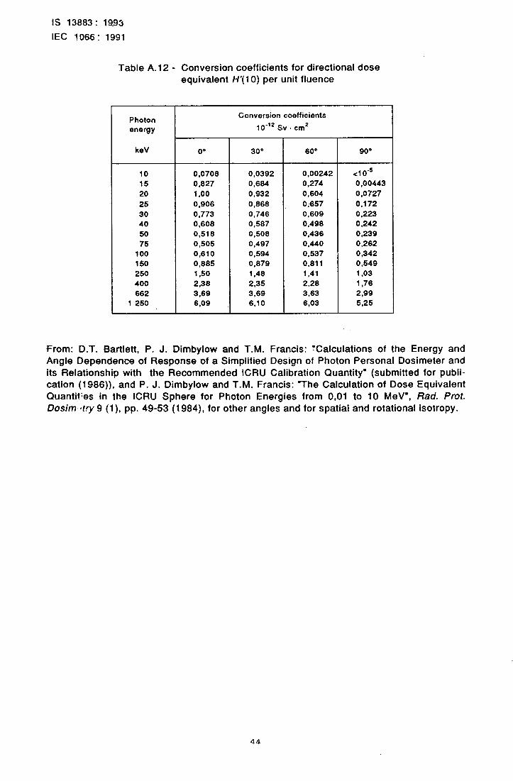
IS 13883~: 1993
IEC 7066: 1991
Table A. 12 - Conversion coefficients for directional dose equivalent H’( 10) per unit fluence
Photon energy
Conversion coefficients
lo-‘* Sv . cm*
keV 00 30” 60” 90’
10 0.0708 0,0392 0.00242 <1o-5
15 0,827 0,684 0.274 0 .OO443
20 1 ,oo 0,932 0.604 0.0727
25 0,906 0,868 0,657 0.172
30 0,773 0,746 0,609 0,223 40 0.608 0.587 0,498 0.242
50 0,518 0,508 0,436 0,239
75 0,505 0,497 0.440 0,262
100 0.610 0.594 0,537 0,342 150 0,885 0.879 0.811 0,549
250 1,50 1.48 1,41 1.03
400 2,38 2,35 2.28 1,76
662 3,69 3.69 3.63 2,QQ 1 250 6,09 6.10 6,03 5.25
From: D.T. Bartlett, P. J. Dimbylow and T.M. Francis: Xalculations of the Energy and Angle Dependence of Response of a Simplified Design of -Photon Personal Dosimeter and its Relationship with the Recommended ICRU Calibration Quantity” (submitted for publi- cation (1986)), and P. J. Dimbylow and T.M. Francis: “The Calculation of Dose Equivalent C?uantif;es in the ICRU Sphere for Photon Energies from 0,Ol to 10 MeV”, Rad. Pmt. Dosim~try 9 (l), pp. 49-53 (1984), for other angles and for spatial and rotational isotropy.
44
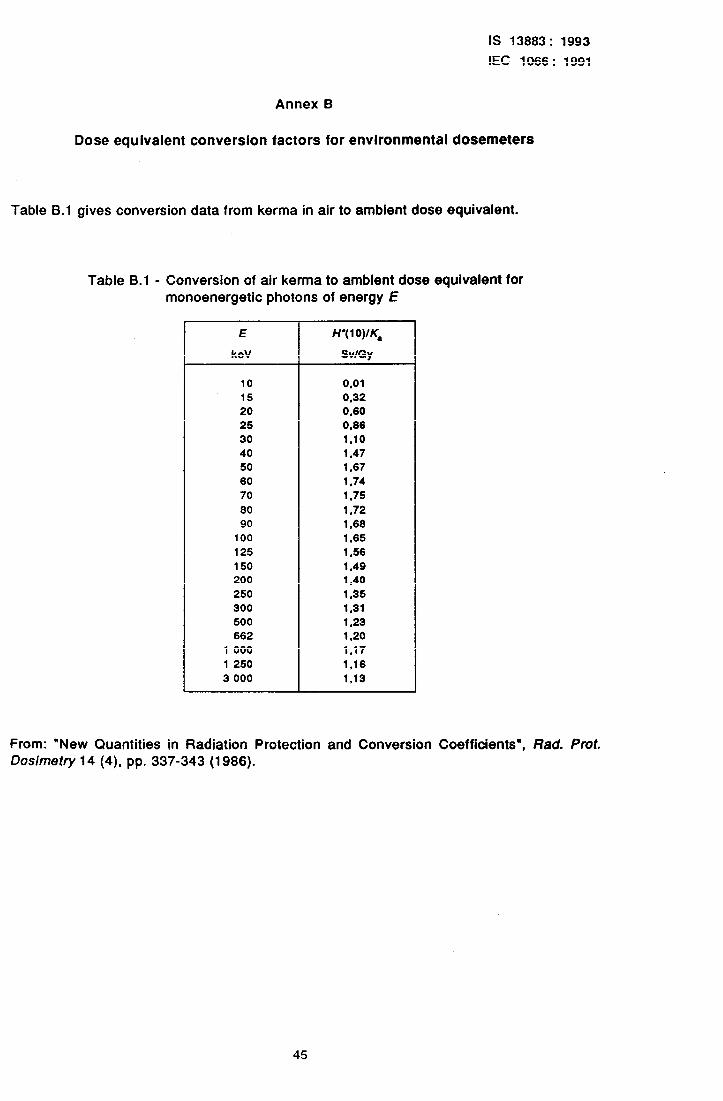
IS 13883: 1993
IEC 1066: 1991
Annex B
Dose equivalent conversion factors for environmental dosemeters
Table 6.1 gives conversion data from kerma in air to ambient dose equivalent.
Table B.l - Conversion of air kerma to ambient dose equivalent for monoenergetic photons of energy E
E
keV
H'(lO)lK,
SvlGy
10 0.01 15 0,32 20 0.60 25 0.86 30 1.10 40 1,47 50 1,67 60 1,74 70 1.75
80 1.72 90 1.68
100 1,65 125 1,56 150 1.49 200 1.40 250 1,35 300 1,31 500 1.23 662 1.20
1 000 1.17 1250 1,16 3 000 1.13
From: “New Quantities in Radiation Protection and Conversion Coefficients”, Rad. Prot. Dosimetry 14 (4) pp. 337-343 (1986).
45
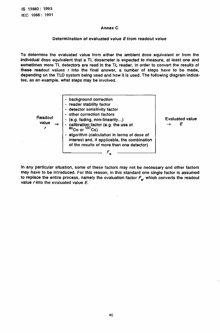
IS 13883: 1993
IEC 1066: 1991
Annex C
Determination of evaluated value E from readout value
To determine the evaluated value from either the ambient dose equivalent or from the individual dose equivalent that a TL dosemeter is ~expected to measure, at least one and sometimes more TL detectors are read in the TL reader. in order to convert the results of these readout values r into the final answer, a number of steps have to be made, depending on the TLD system being used and how it is used. The following diagram indica- tes, as an example, what steps may be involved.
Readout value +
f
background correction reader stability factor detector sensitivity factor other correction factors (e.g. fading, non-linearity...) calibration factor (e.g. the use of 6oCo or “‘Cs) algorithm (calculation in terms of dose of interest and, if applicable, the combination of the results of more than one detector)
I- ‘8
Evaluated value + E
in any ~particular situation, some of these factors may not be necessary and other factors may have to be introduced. For this reason, in this standard one single factor is assumed to replace the entire process, namely the evaluation factor Fe, which converts the readout value rinto the evaluated value E.
46
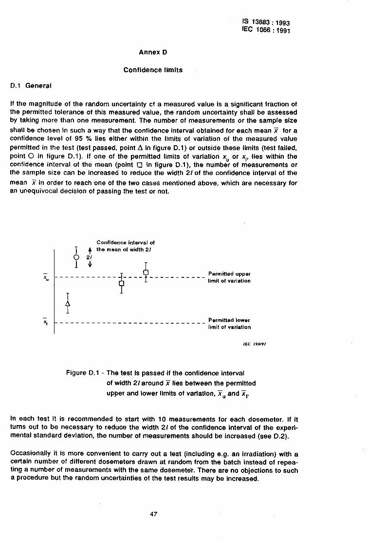
IS 13883 : 1993 IEC 1066 : 1991
Annex D
Confidence limits
D. 1 General
If the magnitude of the random uncertainty cf a measured value is a significant fraction of the permitted tolerance of this measured value, the random uncertainty shall be assessed by taking more than one measurement. The number of measurements or the sample size
shall be chosen in such a way that the confidence interval obtained for each mean ?T for a confidence level of 95 % lies either within the limits of variation of the measured value permitted in the test (test passed, point A in figure D.l) or outside these limits (test failed, point 0 in figure -D.l). If one of the permitted limits of variation xU or x,, fies within the confidence interval of the mean (point 0 in figure D.l), the number of measurements or the sample size can be increased to reduce the width 2/of the confidence interval of the
mean X in order to reach one of the two cases mentioned above, which are necessary for an unequivocal decision of passing the test or not.
Confidence interval of
T i? the mean of width 21
P + T
d P -----_-_-- _--- _____--____ Permitted upper
limit of variation
Permitted lower ___________-_-_--c__-_-_--- limit of variation
IEC 196191
Figure D.l - The test is passed if the confidence interval
of width 2/ around ST lies between the permitted
upper and lower limits of variation, Y,, and ST,.
In each test it is recommended to start with 10 measurements for each dosemeter. If it turns out to be necessary to reduce the width 21 of the confidence interval of the experf- mental standard deviation, the number of measurements should be increased (see D.2).
Occasionally it is more convenient to carry out a test (including e.g. an irradiation) with a certain number of different dosemeters drawn at random from the batch instead of repea- ting a number of measurements with the same dosemeter. There are no objections to such a procedure but the random uncertainties of the test results may be increased.
47
IS 13883: 1993
IEC 1066: 1991
D.2 Confidence interval for fhe experimental standard deviation (s)
The confidence interval for the experimental standard deviation of the means s, is:
where IS is the half-width of the confidence interval of s. If s is calculated from ns measure- ments, the upper limit of /* at a confidence level of 95 % is given by:
is (n,) - tns - d o&j * $ - ns-1
(1)
By way of example 1, (10) = 0,53 - s is obtained for 10 dosemeters.
0.3 Mean, ‘jT
The confidence interval for the mean (Y) is:
(~ - lil X + /i)
where Ii is the half-width of the confidence interval of _ relative to the Cth set of measure-
ments. When calculating X from ni measurements, the half-width of the confidence interva! is given by:
where si is the standard deviation for the Cth group of measurements, and tni is taken from
table D.1 for ni measurements. For example, for ni - IO, Ii - 2,26 / m - si = 0,71 - si.
Table D.l
“i I t ni
2 3 4 5 6 7 3 9 10
lb
20 25 30 40 60
120 00
12,71 4.30
3,16 2,7S 2.57 2,45 2.37 2,31 2.26
2.15 2.09 2,06 2,05 2.02 2.00 1,96 1.96
IS 13883: 1993
IEC 1066: 1991
D.4 Confidence interval for a combined quantity
If the limits of variation are stated for a quantity (X) calculated from k independent means
x,, ST,, Ys, . . . , q:
and the half-width of the confidence interval of the Cth mean is li, the half-width (I) of the
confidence interval for 5? is given by
Examples:
f) hence I- r: + 1;
in general hence I =
2)
3) ST= x, - T2
hence I = ST, + ST,
49
IS 13883: 1993
IEC 1066: 1991
Annex E
Bibliography
IEC 846: 1989, Beta, X and gamma radiation dose equivalent and dose equivalent rate meters for use in radiation protection.
IS0 4071: 1978, Exposure meters and dosemeters - Genera/ methods for testing.
EUR 5287: 1975, Technical Recommendations for monitoring the exposure of individuals to external radiation. Commission of the European Communities.
EUR 5358: 1975, Technical Recommendations for the use of thermoluminescence for dosi-
metty in individual monitoring for photons and electrons from external sources. Commis- sion of the European Communities.
ICRU Report No. 20: 1971, international Commission on Radiation Units and Measufe-
ments. Radiation protection instrumentation and its application.
ICRU Report No. 23: 1973, international ments. Measurement of absorbed dose in gamma rays.
Commission on Radiation Units and Measure- a phantom irradiated by a single beam of X or
ICRP Report No. 26: 1977, Recommendations of the lntemational Commission on Radio- logical Protection, Pergamon Press.
ICRP Report No. 35: 1982, international Commission on Radiological Protection. Genera/ principles of monitoring for radiation protection of workers.
50 - Printed at Dee Kay Printers. New Delhi, India
Standard Mark
The use of the Standard Mark Is governed by the provirtonr of the Bureau ofIn&n Stmdurds Act, 1986 and the Rules and Regulations made thereunder. The Standard Mark on products covered by an Indian Standard conveys the assurance that they have been produced to comply with the requirements of that standard under a well defined system of inspection, testing and quality control which is devised and supervised by BIS and operated by the producer. Standard marked products are also continuously checked by BIS for conformity to that standard as a further safeguard. Details of conditions under which a licence for the use of the Standard Mark may be granted to manufacturers or producers may be obtained from the Bureau of Indian Standards.
Bureau of Indian Standards
BIS is a statutory institution established under the Burecru of Indian Standards Act, lW6 to promote harmonious development of the activities of standardization, marking and quality certification of goods and attending to connected matters in the country.
Copyright
BIS has the copyright of all its publicatrons. No part of these publications may be reproduced in any form without the prior permission in writing of BIS. This does not pre~clude the free use, in the course of implementing the standard, of necessary details, such as symbois and sizes, type or grade designations. Enquiries relating to copyright be addressed to the Director ( Publications 1. RIS.
Revision of Indian Standards
Amendments are issued to standards as the need arises on the basis of comments. Standards are also reviewed periodically; a standard along with amendments is reaffirmed when such review indicates that no changes are needed; if the review indicates that changes are needed, it is taken up for revision. Users of Indian Standards should ascertain that they are in possession of the latest amendments Dr edition by referring to the latest issue of ‘BIS Handbook and ‘Standards Monthly Additions’. Comments on this Indian Standard may be sent to BIS giving the following reference:
Dot : No. LTD 26 ( 1409 )
Amendments Issaed Slncc Poblicatla~
Amend No Date of Issue Text Affected
Headquarters:
BUREAU OF INDIAN STANDARDS
Manak Bhavan, Y -Bahadur Shah Zafar Marg New Delhi 110002 Telephones : 331 01 31. 331 13 ‘75 Telegrams : Manaksansthe
( Common to all Offices )
Regional Otilces * Telephone
Central : Manak Bhavan, Y Bahadur Shah Zafar Marg 331 01 31 NEW DELHI 110002 331 13 75
Eastern : l/l4 C. I. T. Scheme VII M, V. I. B. Road, Maniktola 37 g4 99, 37 85 6-l
CALCUTTA 700054 37 86 26, 37 86 62
Northern : SC0 445-446, Sector 35-C, CHAND-IGARH 160036
Southern : C. I. T. Campus, IV Cross Road, MADRAS 600113
53 16 40
235 04 42 235 23 I5
Western : Manakalaya, E9 MIDC, Marol, Andheri ( East ) 632 92 95, 632 78 58 BOMBAY 400093 632 78 9 1, 632 78 92
Branches : AHMADABAD. BANGALORE. BHOPAL. BHUBANESHWAR. COIMBATORE. FARIDABAD. GHAZIABAD. GUWAHATI. HYDERABAD. JAIPUR. KANPUR. LUCKNOW. PATNA. THIRUVANANTHAPURAM.
Printed at Printwell Printers, Aligarh, India