Optical Fiber Force Myography Sensor for Identification of ...
11
Research Article Optical Fiber Force Myography Sensor for Identification of Hand Postures Eric Fujiwara and Carlos Kenichi Suzuki Laboratory of Photonic Materials and Devices, School of Mechanical Engineering, University of Campinas, 13080-860 Campinas, SP, Brazil Correspondence should be addressed to Eric Fujiwara; [email protected] Received 28 October 2017; Revised 16 December 2017; Accepted 7 February 2018; Published 19 March 2018 Academic Editor: Andrea Cusano Copyright © 2018 Eric Fujiwara and Carlos Kenichi Suzuki. This is an open access article distributed under the Creative Commons Attribution License, which permits unrestricted use, distribution, and reproduction in any medium, provided the original work is properly cited. A low-cost optical fiber force myography sensor for noninvasive hand posture identification is proposed. The transducers are comprised of 10 mm periodicity silica multimode fiber microbending devices mounted in PVC plates, providing 0.05 N -1 sensitivity over ~20 N range. Next, the transducers were attached to the user forearm by means of straps in order to monitor the posterior proximal radial, the anterior medial ulnar, and the posterior distal radial muscles, and the acquired FMG optical signals were correlated to the performed gestures using a 5 hidden layers, 20-neuron artificial neural network classifier with backpropagation architecture, followed by a competitive layer. The overall results for 9 postures and 6 subjects indicated a 98.4% sensitivity and 99.7% average accuracy, being comparable to the electromyographic approaches. Moreover, in contrast to the current setups, the proposed methodology allows the identification of poses characterized by different configurations of fingers and wrist joint displacements with the utilization of only 3 transducers and a simple interrogation scheme, being suitable to further applications in human-computer interfaces. 1. Introduction The design of intuitive and feasible sensors and techniques for hand posture detection plays an important role on the establishment of advanced human-computer interfaces, with further applications in teleoperation [1], medical [2] and rehabilitation robots [3], bionic prosthesis control [4], and gesture recognition for consumer electronics [5]. Nowadays, different approaches have been developed for the direct assessment of the hand movements, mainly comprising optical tracking [6] and glove-based sensors [7]. Even though these technologies can provide reasonable results for practical applications, limitations are still observed concerning occlusion, complexity, and restrictions to the user movements [3, 6, 7]. Alternatively, myographic techniques can be utilized for monitoring the hand gestures and forces in a noninvasive way by detecting the muscular activities on the user forearm, so it is also possible to retrieve the motion intentions in case of disabled subjects. The surface electromyography (sEMG) is the most widespread approach for pose estimation [8], in which the electrical signals produced during muscle contrac- tions are recorded by electrodes placed over the user skin and then processed to determine the related hand movements. Although several works have reported the application of sEMG on prosthesis control [9, 10], such technique still presents limitations in terms of cost and reliability. The elec- tromyography signals are severely affected by electromag- netic noise, sweat, and variations of transducer placement. Moreover, the application of feature extraction procedure over a large number of channels is required in order to decode the subject motions with a suitable dexterity level [11, 12]. In this context, different methods such as the mechanomyography [13], sonomyography [14], optical myography [15, 16], and the force myography (FMG) [17] have been proposed in order to overcome the drawbacks presented by the myoelectric case. The FMG can be considered as the mechanical counter- part of the sEMG, in which the hand movements are retrieved from the radial forces exerted by the forearm Hindawi Journal of Sensors Volume 2018, Article ID 8940373, 10 pages https://doi.org/10.1155/2018/8940373
Transcript of Optical Fiber Force Myography Sensor for Identification of ...

Research ArticleOptical Fiber Force Myography Sensor for Identification ofHand Postures
Eric Fujiwara and Carlos Kenichi Suzuki
Laboratory of Photonic Materials and Devices, School of Mechanical Engineering, University of Campinas, 13080-860 Campinas,SP, Brazil
Correspondence should be addressed to Eric Fujiwara; [email protected]
Received 28 October 2017; Revised 16 December 2017; Accepted 7 February 2018; Published 19 March 2018
Academic Editor: Andrea Cusano
Copyright © 2018 Eric Fujiwara and Carlos Kenichi Suzuki. This is an open access article distributed under the Creative CommonsAttribution License, which permits unrestricted use, distribution, and reproduction in any medium, provided the original work isproperly cited.
A low-cost optical fiber force myography sensor for noninvasive hand posture identification is proposed. The transducers arecomprised of 10mm periodicity silica multimode fiber microbending devices mounted in PVC plates, providing 0.05N−1
sensitivity over ~20N range. Next, the transducers were attached to the user forearm by means of straps in order to monitor theposterior proximal radial, the anterior medial ulnar, and the posterior distal radial muscles, and the acquired FMG opticalsignals were correlated to the performed gestures using a 5 hidden layers, 20-neuron artificial neural network classifier withbackpropagation architecture, followed by a competitive layer. The overall results for 9 postures and 6 subjects indicated a98.4% sensitivity and 99.7% average accuracy, being comparable to the electromyographic approaches. Moreover, in contrast tothe current setups, the proposed methodology allows the identification of poses characterized by different configurations offingers and wrist joint displacements with the utilization of only 3 transducers and a simple interrogation scheme, being suitableto further applications in human-computer interfaces.
1. Introduction
The design of intuitive and feasible sensors and techniquesfor hand posture detection plays an important role on theestablishment of advanced human-computer interfaces, withfurther applications in teleoperation [1], medical [2] andrehabilitation robots [3], bionic prosthesis control [4], andgesture recognition for consumer electronics [5].
Nowadays, different approaches have been developedfor the direct assessment of the hand movements, mainlycomprising optical tracking [6] and glove-based sensors[7]. Even though these technologies can provide reasonableresults for practical applications, limitations are still observedconcerning occlusion, complexity, and restrictions to theuser movements [3, 6, 7].
Alternatively, myographic techniques can be utilized formonitoring the hand gestures and forces in a noninvasiveway by detecting the muscular activities on the user forearm,so it is also possible to retrieve the motion intentions in caseof disabled subjects. The surface electromyography (sEMG)
is the most widespread approach for pose estimation [8], inwhich the electrical signals produced during muscle contrac-tions are recorded by electrodes placed over the user skin andthen processed to determine the related hand movements.Although several works have reported the application ofsEMG on prosthesis control [9, 10], such technique stillpresents limitations in terms of cost and reliability. The elec-tromyography signals are severely affected by electromag-netic noise, sweat, and variations of transducer placement.Moreover, the application of feature extraction procedureover a large number of channels is required in order todecode the subject motions with a suitable dexterity level[11, 12]. In this context, different methods such as themechanomyography [13], sonomyography [14], opticalmyography [15, 16], and the force myography (FMG) [17]have been proposed in order to overcome the drawbackspresented by the myoelectric case.
The FMG can be considered as the mechanical counter-part of the sEMG, in which the hand movements areretrieved from the radial forces exerted by the forearm
HindawiJournal of SensorsVolume 2018, Article ID 8940373, 10 pageshttps://doi.org/10.1155/2018/8940373
muscles, producing results comparable to the electricalapproach [18]. In contrast to other techniques, the FMG isless affected by variations in sensor placement, exhibitinghigher robustness and stability, and does not demand expen-sive hardware for implementation. The mechanical stimuliare typically measured using arrays of force sensing resistors(FSR) or capacitive sensors attached to the user forearm bymeans of orthoses or straps [18, 19], providing the pressuredistribution maps for particular hand configurations. How-ever, such transducers exhibit drawbacks in terms of hyster-esis, drift, and vulnerability to electromagnetic interference[20], being also affected by skin impedance variations.
In this context, optical fiber sensors (OFS) are consid-ered promising alternatives for biomechanical measure-ments, presenting intrinsic characteristics like flexibility,lightweight, high sensitivity, distributed sensing capability,and immunity to electromagnetic interference. Furthermore,silica fibers are chemically and biologically inert [21]. Cur-rently, several examples of OFS applications in human-system interfaces have been reported, including vital signmonitoring for healthcare [22], tactile matrixes [23], andglove-based sensors [24]. Moreover, the utilization of anoptical fiber sensor for FMG measurements was presentedin recent studies, providing 89.9% accuracy on the predictionof individual finger movements [25].
In this paper, an intensity-based optical fiber FMG sensorfor posture identification is proposed. The optomechanicaltransducers are attached to the forearm by means of strapsto measure the forces produced by forearm muscles, so theoutput signals are correlated to the hand poses by artificialneural networks (ANN). The utilization of optical fibersensors provides several advantages over the commonlyadopted FSR arrays, yielding higher sensitivity and immunityto sweat and electrical noise. Additionally, in contrast to thepreviously reported fiber specklegram FMG sensors [25],the present setup shows improved robustness (as the guidedlight is less susceptible to vibration and temperature fluctua-tions [26]) and a simpler interrogation setup (since it is notnecessary to process the spatial information of speckle fields[25]) being suitable for further applications in practicalbionic prosthesis control.
2. Optical Fiber FMG Sensor
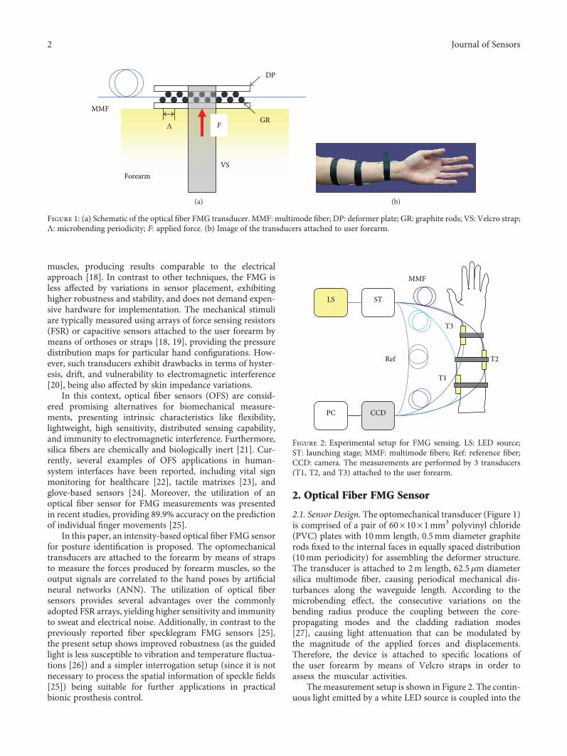
2.1. Sensor Design. The optomechanical transducer (Figure 1)is comprised of a pair of 60× 10× 1mm3 polyvinyl chloride(PVC) plates with 10mm length, 0.5mm diameter graphiterods fixed to the internal faces in equally spaced distribution(10mm periodicity) for assembling the deformer structure.The transducer is attached to 2m length, 62.5μm diametersilica multimode fiber, causing periodical mechanical dis-turbances along the waveguide length. According to themicrobending effect, the consecutive variations on thebending radius produce the coupling between the core-propagating modes and the cladding radiation modes[27], causing light attenuation that can be modulated bythe magnitude of the applied forces and displacements.Therefore, the device is attached to specific locations ofthe user forearm by means of Velcro straps in order toassess the muscular activities.
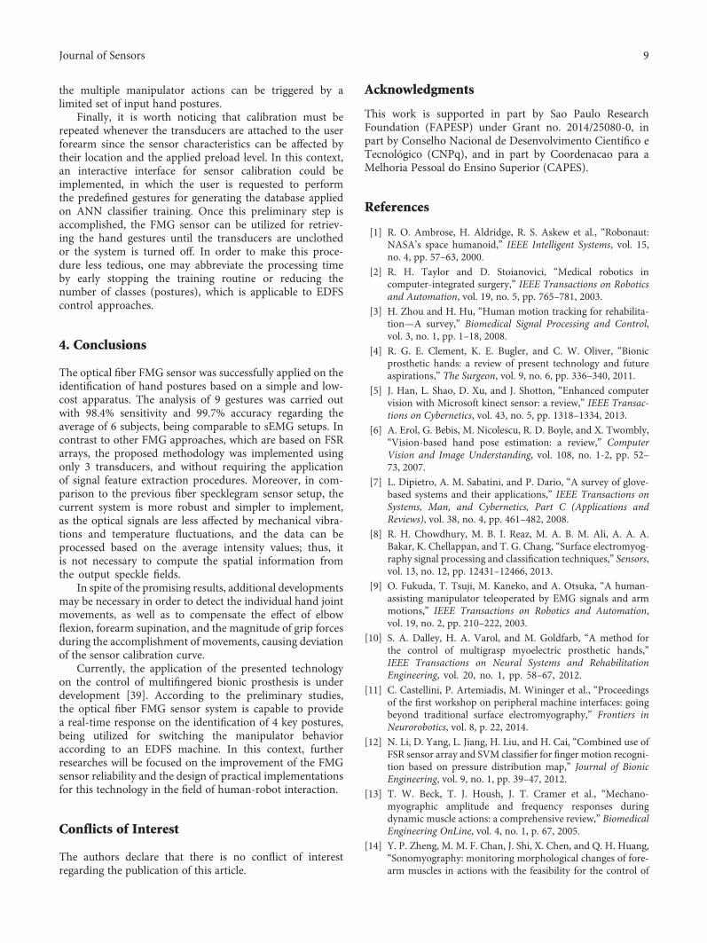
The measurement setup is shown in Figure 2. The contin-uous light emitted by a white LED source is coupled into the
MMF
DP
GR
VSForearm
FΛ
(a) (b)
Figure 1: (a) Schematic of the optical fiber FMG transducer. MMF: multimode fiber; DP: deformer plate; GR: graphite rods; VS: Velcro strap;Λ: microbending periodicity; F: applied force. (b) Image of the transducers attached to user forearm.
LS ST
CCDPC
T1
T2
T3
MMF
Ref
Figure 2: Experimental setup for FMG sensing. LS: LED source;ST: launching stage; MMF: multimode fibers; Ref: reference fiber;CCD: camera. The measurements are performed by 3 transducers(T1, T2, and T3) attached to the user forearm.
2 Journal of Sensors

multimode fibers using a micrometric stage. The transmittedlight intensity is modulated by the microbending transduc-ers, being further detected by a CCD camera (u-EYE IDSUI-2230SE-C-HQ, 1024× 768 pixels resolution, 15 fps rate).The plane-polished fiber end faces are aligned, fixated in astable support, and placed 5 cm from the camera lens. Then,the setup is enclosed in a dark box for eliminating theexternal illumination effect and kept in an environment freefrom mechanical vibrations. An additional reference fiber isalso utilized for compensating the source fluctuations.Finally, the acquired optical signals are processed by routinesprogrammed in MATLAB, MathWorks, and the averageintensity I for each frame is evaluated by computing themean of a 40× 40 pixels region-of-interest within the fiberoutput light spots.
2.2. Characterization. In order to determine the sensorresponse, the device was subjected to controlled forcesapplied by a mechanical stage provided with a load cell.The experimental setup for transducer characterization isshown in Figure 3. The actuator probe is comprised of a2.5mm diameter spherical-shaped structure driven by ascrew mechanism, which is aligned to the deformer platecenter to produce a concentrated load. As the micrometricstage is activated, the actuator position is displaced inthe y-direction, causing the transducer to be pressed andproducing optical attenuation. Then, the mechanical stimu-lus is measured by the load cell, yielding the applied forcevalue, whereas the output light is continuously monitoredby the CCD, making it possible to correlate the averageintensity I with the input forces.
The static characterization was carried out by subjectingthe microbending transducer to 3 upscale and downscalecycles, with the application of loads ranging from 0 to~22N. Once the actuator position is changed, the force levelis kept static for ~100 acquisition frames. Finally, the calibra-tion curve can be obtained by averaging the intensity valuesfor each constant force interval regarding all upscale/downscale cycles, and the sensitivity is determined byadjusting the experimental data by a linear function.
The sensor static response is shown in Figure 4, whereasthe variation of I for repeated loading cycles is illustrated inFigure 5. The device presented ~0.05N−1 sensitivity overthe investigated range. In comparison to FSR [20], the fibersensor exhibited negligible linearity error with low hysteresis,being suitable for assessing the force magnitudes typically
exerted by forearm muscles and repetitive cycles of muscularstretching and contraction [28]. In spite of the reliableresults, it is worth noticing that the transducer responsemay be degenerated by changes on the deformer structurein case of severe loading conditions, whereas the intensityoutput values can be affected by variations on fiber mechan-ical characteristics and macrobending [27].
3. Posture Identification by FMG
3.1. Measurement Protocol. The sensor performance wasevaluated on the identification of 9 postures, as shown inTable 1 and Figure 6. For retrieving the information relativeto each pose, the system was implemented using 3 transduc-ers located to monitor the posterior proximal radial (T1), theanterior medial ulnar (T2), and the posterior distal radial(T3) sections of the forearm. In practice, as the muscles are
MMF
F
Transducer
Load cell
Stage
y
Figure 3: Experimental setup for transducer characterization.
R2 = 0.998
5 10 15 20 250Force F (N)
0
0.2
0.4
0.6
0.8
1
Nor
mal
ized
inte
nsity
I
Figure 4: Optical fiber FMG sensor response to applied forces.
0 10 20 30 40 50 60
10 20 30 40 50 600Measurements
0
0.5
1In
tens
ity I
0
10
20
Forc
e F
(N)
Figure 5: Variation of normalized intensity values during 3downscale-upscale cycles. The input forces are shown in thebottom curve.
3Journal of Sensors

presented in layered structure [29], the measured mechanicalstimuli will be equivalent to the overall radial forces pro-duced by the muscles enclosed inside each strap rather thanthe activation of a single tissue.
The experiments were conducted for 6 healthy subjects(5 male and 1 female, 29± 4 years old, namely, S1 to S6)following the Ethical Committee recommendations, bytightly adjusting the straps to create a moderate preload,but preserving the comfort for the user. The transducer
locations were determined by muscle palpation, so eventualvariations in the placement of the sensors for the differ-ent subjects are expected. During the tests, the volunteerswere requested to keep the wrist with neutral supination/pronation and the elbow flexed to maintain the forearmhorizontally suspended in air. After receiving a visualcommand, the users performed a sequence of hand postures(A, B,… , N) by sustaining the static hand condition during~100 acquisition frames. Finally, the acquired data for each
Table 1: Posture set for evaluation of the classifier performance.
ID Posture Description
A Open hand Open hand with finger joint extension, without metacarpophalangeal joint abduction/adduction
B Clench Closed hand with fingers and thumb flexion
C Wrist extension Wrist extension with fingers in neutral condition
D Wrist flexion Wrist flexion with fingers in moderate flexion condition
E Finger abduction Open hand with finger joint extension and metacarpophalangeal joint abduction/adduction
F Index finger Index finger extension with flexion of other joints
G V sign Index and medium finger extension with flexion of other joints
H Thumb up Thumb joint extension with flexion of other joints
N Relaxed hand Open hand in natural/relaxed condition
A B C
D E F
G H N
Figure 6: Analyzed hand postures.
4 Journal of Sensors

pose were windowed to remove the transient components ofintensity signals (due to hand configuration changes) andthen reduced by computing the average value for each timeinterval. The experiments were repeated 10 times for eachsubject, with simultaneous acquisition of optical signals andfurther correlation to the input postures through time syn-chronization, that is, since each pose was performed duringparticular frame intervals, the corresponding intensity valuescan be properly retrieved by indexing the initial and finalframe numbers regarding each posture in the acquiredoptical data array.
3.2. Data Analysis. In order to retrieve the performed posesfrom the FMG data, an ANN classifier was designed byaddressing the acquired average intensity values to the net-work input, and the degree of target posture matching(ranging from 0 to 1) to the output, as illustrated inFigure 7. For the sake of simplicity, the classifier was devel-oped using individual networks for processing each posture,yielding 9 subsystems integrated by a competitive layer. TheANN were implemented according to the feed-forward back-propagation architecture [30], utilizing 5 hidden layers of 20neurons and tangent-sigmoidal transfer functions, whereasthe training function was set to the scaled conjugate gradientlimited to 3000 epochs and 0.05 target error. Subsequently,the output matching rates are submitted to a winner-take-all competitive layer, returning the final classification esti-mated from the FMG input signals.
For evaluating the network response, the classificationswere carried out for each subject following a 10-fold crossvalidation analysis [31]. Given the number of true positive(TP), true negative (TN), false positive (FP), and false nega-tive (FN) predictions, the performance metrics for a singlefold can be expressed in terms of [32]
tp = TPTP + FN
, 1
fp =FP
TN + FP, 2
ac =TP + TN
TP + TN + FP + FN, 3
where tp is the true positive rate (sensitivity), fp is the falsepositive rate, and ac is the accuracy. Therefore, the scoresfor a particular posture can be obtained by computing theaverage of the 10 folds, whereas the overall performancecan be estimated from the average for all volunteers.
3.3. Results. The effect of hand pose on the transducerresponse for a single subject (S3) is shown in Figure 8, whereI1, I2, and I3 correspond to the normalized intensity valuesobtained by transducers T1, T2, and T3, respectively. Thetransient parts of the curves are due to the changes in handconfiguration during posture transitions. Additionally, thestatic response was found to be practically constant, withsubtle variations possibly caused by involuntary contractions,dither, and fatigue [18].
Regarding the average results for all volunteers (Figure 9),it is observed that the optical attenuation for transducer T1
increases with the wrist and finger flexion, which can beassociated to the activation of the flexor digitorum superficia-lis (FDS) and flexor digitorum profundus (FDP) muscles,whereas I2 and I3 present improved response to sense thejoint extension due to the contribution of the extensor digi-torum communis (EDC). For example, the clench poses B,F, and H, as well as the wrist flexion D, cause I1 to decrease,and I2 and I3 to increase, indicating the activation of flexorsand relaxation of the extensor muscles, respectively. Con-versely, performing open hand pose with finger abduction/adduction conditions or wrist extension produces attenua-tion of I2 and I3 and recovering of the I1 level. Concerningthe abduction/adduction movements, the thumb action can
I1
A
B
N
Com
petit
ive l
ayer
⋯
Posture
[0, … , 1]
[0, … , 1]
[0, … , 1]
% A
% B
% C
[A, … , N]
I2
I3
Figure 7: ANN classifier with competitive layer for hand postureidentification. The system is comprised of 9 individual networksfor processing each posture, whereas the results are combined bythe competitive layer.
0.0
5
1
I 1
0
0.5
1
I 2
0
0.5
1
I 3
FC D EB G H NAPostures
Figure 8: Normalized intensity as a function of the hand posture forsubject S3. Intensities I1, I2, and I3 correspond to transducers T1, T2,and T3, respectively.
5Journal of Sensors

be recognized from I3 value, as the transducer T3 was locatedclose to the abductor/extensor pollicis (AEP) muscles,whereas the effect of other digits is detectable through T2response, as noticed in postures E and G, given that the fingerabduction/adduction are assisted by the EDC.
In addition to the physiological differences among sub-jects, the results may vary due to the sensor fixation andplacement, affecting the preload and the pressure distribu-tion over the microbending device. Moreover, even thoughthe experiments were conducted under a strict protocol, themeasurements are also expected to change with the magni-tude of grip forces, as well as the degree of forearm flexionand wrist rotation. Particularly, it is relatively difficult tostipulate an exact condition for posture N (relaxed hand),so the deviations on intensity values for this case wereobserved. Additionally, one may notice that the system pre-sented reproducible results considering all subjects exceptfor the I2 value, pose C, yielding large deviation. This effectcan be attributed to uncontrolled variations in the degree ofwrist extension, as well as on the magnitude of forcesinvolved in such posture. Another possible aspect is theinvoluntary finger abduction during the wrist movementssince the EDC is also related to the abduction/adduction ofthe metacarpophalangeal joints.
The muscular structure of the forearm is very complex,being comprised of extensors and flexor entities arranged ina layered fashion. Although the FMG sensor was designedto monitor the muscles responsible for finger and wristmovements, structures related to the elbow flexion and fore-arm pronation, such as the brachioradialis and the pronatorteres, respectively, also produce mechanical stimuli due theiractivation [29], affecting the magnitude and range of theFMG signals related to specific hand poses. This fact can beconfirmed by sEMG-based studies, in which the experimentswere conducted for more complicated scenarios, includingsequential arm movements and application of mechanicalloads, so the overall performance was deteriorated due tochanges on upper limb configuration [33]. Possible solutions
for such problem comprise extracting additional informationfrom the output waveforms or eventually attaching com-plementary transducers in order to provide a completecharacterization of the assessed poses.
Regarding the effect of applied forces, subtle variationswere expected because of fatigue and subject-related uncer-tainties. With respect to the correlation between muscularforces and the upper limb configuration, it was reported thatthe electrical response in sEMG schemes can be affectedby the muscle length and elastic properties, fatigue, con-traction velocity and type, and the contribution of tendonsand ligaments [34]. Moreover, the magnitude and range ofgrip forces are also influenced by the forearm and wristconfigurations [35].
The ANN classification results for all postures and sub-jects are summarized in Table 2, whereas the confusionmatrixes are shown in Figure 10. The system provided areliable overall performance, yielding 98.4± 1.7% sensitivityand 99.7± 0.4% average accuracy. In particular, subjects S3and S4 presented a perfect score, whereas the poorest resultswere observed for subject S1, resulting 98.9± 1.2% accuracy,which was probably caused by errors on the transducerplacement or application of excessive forces during fingerflexion on postures F, G, and H. Most of misclassifyingoccurred for gestures A and E, comprising the open handcase with the presence or absence of finger abduction/adduction, respectively. As aforementioned, the digit separa-tion produced by metacarpophalangeal (MCP) joints can beretrieved from the EDC muscle, but such movement isbounded to the extension of proximal interphalangeal (PIP)joints, so the differentiation between postures A and Ebecomes very subtle. Fortunately, the thumb abductionactivates the AEP muscle; therefore, most of the ambiguitiescan be solved based on I3 value, as also observed for posesB and H. Moreover, it is worth noticing that the wrist exten-sion (C) and flexion (D) were successfully discriminatedfrom the finger movement (A and B, resp.), although suchdisplacements are partially driven by the same group ofmuscles (EDC and FDS, resp.). A possible explanation isgiven by the differences in force magnitude and the numberof activated muscles involved in each situation since theoptical fiber sensors actually measure the overall forcesexerted by all enclosed muscles. The classifications were alsosucceeded concerning postures F and G, characterized by thesame hand configuration except by the ring finger flexion orextension, respectively, demonstrating the proposed tech-nique capability to track the movement of individual digits.Finally, one may observe that the overall sensitivity forpose N was reduced due to the variations on hand neutralconfiguration, as previously explained.
A compilation of different approaches for assessing thehand gestures by myographic techniques is summarized inTable 3. It must be stressed that the purpose of Table 3 ismerely informative, as the direct comparison betweentechniques should consider experiments conducted underthe same conditions and analyzed poses.
The utilization of sEMG on the identification of handpostures had been proposed in several works, as observedin [36], which is based on 2 electrodes applied in conjunction
0
0.5
1
I 1
0
0.5
1
I 2
0
0.5
1
I 3
A C D E F G H NBPostures
Figure 9: Normalized intensity as a function of the hand postureregarding the average for all subjects.
6 Journal of Sensors

with a linear Bayesian classifier to evaluate 16 hand configu-rations, providing ~85% average accuracy. Another researchdemonstrated the combination of 5 sEMG electrodes and a3D accelerometer to identify 18 postures, including dynamicgestures [37]. By applying a hidden Markov model-baseddata fusion technique, it was possible to obtain a 97.6% aver-age accuracy. In contrast to the mechanical analysis, as theelectromyographic signal processing requires feature extrac-tion from noisy data, it is necessary to improve the detectionscheme and increase the number of measurement channelsin order to achieve higher hit rates.
A detailed comparison between sEMG and FMG wasalso presented in [18], in which the electrical measurementswere carried out with 10 electrodes arranged along a strip,whereas the muscle mechanical forces were obtained using6 FSR attached to an orthosis. The system was tested forrecognizing the flexion of individual fingers with ridgeregression method, yielding normalized root-mean-squareerrors (nRMSE) ranging from 10 to 20%. In spite of thecomparable performances, the sEMG electrodes are typicallymore expensive and less robust than the FSR, makingthe mechanical approach more suitable for consumer
applications. Moreover, the FMG do not demand thewaveform feature extraction for pose classification, asshown in the present research.
Concerning the FMG implementations, in [19], an 8 FSRstrap was utilized for discriminating among 6 gestures,including the elbow flexion and wrist rotation. Based on anelectronic learning machine classifier, the methodology pro-vided 92.33% accuracy with real-time performance. Alterna-tively, the identification of 17 hand postures comprisingcombinations of flexed fingers was proposed in [12]. Thesystem was designed using a 32 FSR socket and signal pro-cessing by support vector machines, yielding >99% accuracy.However, such methodologies require an excessive numberof piezoresistive transducers and signal channels, makingtheir implementation more complicated in comparison tothe proposed work, in which the measurements can beaccomplished using only 3 transducers.
Finally, with respect to the previous version of the opticalfiber FMG sensor [25], the measurements were carried outusing 4 microbending transducers based on specklegraminterrogation and ANN processing. An 89.9% accuracy wasachieved regarding the identification of individual finger
Table 2: Overall classifier performance for all postures and subjects, regarding the average of 10 folds. tp: true positive ratio; fp: false positiveratio; ac: accuracy.
Posture S1 S2 S3 S4 S5 S6 Mean
Atp = 95.0%fp = 0.6%ac = 98.9%
tp = 98.0%fp = 0.2%ac = 99.6%
tp = 100.0%fp = 0.0%ac = 100.0%
tp = 100.0%fp = 0.0%ac = 100.0%
tp = 88.0%fp = 1.5%ac = 97.3%
tp = 89.0%fp = 1.4%ac = 97.6%
tp = 95.0± 5.4%fp = 0.6± 0.7%ac = 98.9± 1.2%
Btp = 100.0%fp = 0.0%ac = 100.0%
tp = 100.0%fp = 0.0%
ac = 100.0%
tp = 100.0%fp = 0.0%ac = 100.0%
tp = 100.0%fp = 0.0%ac = 100.0%
tp = 100.0%fp = 0.0%ac = 100.0%
tp = 100.0%fp = 0.0%ac = 100.0%
tp = 100± 0%fp = 0.0± 0.0%ac = 100± 0%
Ctp = 87.0%fp = 1.6%ac = 97.1%
tp = 99.0%fp = 0.1%ac = 99.8%
tp = 100.0%fp = 0.0%ac = 100.0%
tp = 100.0%fp = 0.0%ac = 100.0%
tp = 100.0%fp = 0.0%ac = 100.0%
tp = 100.0%fp = 0.0%ac = 100.0%
tp = 97.2± 5.2%fp = 0.3± 0.7%ac = 99.5± 1.2%
Dtp = 100.0%fp = 0.1%ac = 99.9%
tp = 100.0%fp = 0.0%
ac = 100.0%
tp = 100.0%fp = 0.0%ac = 100.0%
tp = 100.0%fp = 0.0%ac = 100.0%
tp = 100.0%fp = 0.0%ac = 100.0%
tp = 100.0%fp = 0.0%ac = 100.0%
tp = 100± 0%fp = 0.0± 0.1%ac = 100± 0%
Etp = 99.0%fp = 0.1%ac = 99.9%
tp = 100.0%fp = 0.0%
ac = 100.0%
tp = 100.0%fp = 0.0%ac = 100.0%
tp = 100.0%fp = 0.0%ac = 100.0%
tp = 100.0%fp = 0.0%ac = 100.0%
tp = 100.0%fp = 0.0%ac = 100.0%
tp = 99.8± 0.4%fp = 0.0± 0.1%ac = 100± 0.1%
Ftp = 98.0%fp = 0.2%ac = 99.6%
tp = 100.0%fp = 0.0%
ac = 100.0%
tp = 100.0%fp = 0.0%ac = 100.0%
tp = 100.0%fp = 0.0%ac = 100.0%
tp = 100.0%fp = 0.0%ac = 100.0%
tp = 100.0%fp = 0.0%ac = 100.0%
tp = 99.7± 0.8%fp = 0.0± 0.1%ac = 99.9± 0.2%
Gtp = 90.0%fp = 1.3%ac = 97.8%
tp = 100.0%fp = 0.0%
ac = 100.0%
tp = 100.0%fp = 0.0%ac = 100.0%
tp = 100.0%fp = 0.0%ac = 100.0%
tp = 100.0%fp = 0.0%ac = 100.0%
tp = 100.0%fp = 0.0%ac = 100.0%
tp = 98.3± 4.1%fp = 0.2± 0.5%ac = 99.6± 0.9%
Htp = 90.0%fp = 1.3%ac = 97.8%
tp = 100.0%fp = 0.0%
ac = 100.0%
tp = 100.0%fp = 0.0%ac = 100.0%
tp = 100.0%fp = 0.0%ac = 100.0%
tp = 100.0%fp = 0.0%ac = 100.0%
tp = 100.0%fp = 0.0%ac = 100.0%
tp = 98.3± 4.1%fp = 0.2± 0.5%ac = 99.6± 0.9%
Ntp = 90.0%fp = 1.3%ac = 97.8%
tp = 100.0%fp = 0.0%
ac = 100.0%
tp = 100.0%fp = 0.0%ac = 100.0%
tp = 100.0%fp = 0.0%ac = 100.0%
tp = 95.0%fp = 0.6%ac = 98.9%
tp = 98.0%fp = 0.2%ac = 99.6%
tp = 97.2± 4.0%fp = 0.4± 0.5%ac = 99.4± 0.9%
Meantp = 94.3± 5.1%fp = 0.2± 0.2%ac = 98.7± 1.1%
tp = 99.7± 0.7%fp = 0.0± 0.1%ac = 99.9± 0.2%
tp = 100.0± 0.0%fp = 0.0± 0.0%ac = 100.0± 0.0%
tp = 100.0± 0.0%fp = 0.0± 0.0%ac = 100.0± 0.0%
tp = 98.1± 4.1%fp = 0.2± 0.5%ac = 99.6± 0.9%
tp= 98.6± 3.6%fp = 0.2± 0.5%ac = 99.7± 0.8%
tp = 98.4± 1.7%fp = 0.2± 0.2%ac = 99.7± 0.4%
7Journal of Sensors

flexion among 11 gestures, but the acquired speckle fields arestrongly affected by mechanical and thermal disturbancesalong the fiber length, so the system must be periodicallyrecalibrated. Moreover, the presented intensity-basedapproach is more robust and can be implemented with aneven simpler setup.
Although the optical fiber FMG sensor presented promis-ing results, some aspects must be considered regarding theanalysis of a more comprehensive collection of postures.For example, the identification of the angular displacementsperformed by a specific finger joint would demand the
utilization of additional sensors and a more intensive calibra-tion, since the individual movements of a digit are usuallybounded to different muscles. Additionally, due to thelayered structure of the forearm flexors and extensors, theactivation of each muscle cannot be retrieved in separatedform by using FMG transducers, so it is necessary to combinethe information from several sensors in order to correctlyestimate the hand movements. Fortunately, applicationsrelated to prosthesis control and human-computer interac-tion can be implemented in an efficient way according toevent-driven finite state machines (EDFS) [38]; therefore,
Table 3: Comparison of several techniques for assessing the hand postures.
Ref. Type Sensors Postures Performance
This FMG 3 OFS 9 postures, including finger and wrist flexion 99.7% accuracy
[36] sEMG 2 electrodes Up to 16 hang postures, including finger and wrist flexion 85% accuracy
[37] sEMG5 electrodes
1 accelerometer18 postures including dynamic gestures and circular movements 97.6% accuracy
[18] sEMG 10 electrodes 5 finger flexion and thumb abduction 10–20% nRMSE
[18] FMG 6 FSR 5 finger flexion and thumb abduction 10–20% nRMSE
[19] FMG 8 FSR 6 gestures including grasp, elbow flexion, and wrist rotation 92.33% accuracy
[12] FMG 32 FSR 17 combinations of finger flexion >99% accuracy
[25] FMG 4 OFS 11 postures for identification of finger flexion 89.9% accuracy
S1 S2 S3
S4 S5 S6
0
0.2
0.4
0.6
0.8
1
NHGFEDCBA
Actu
al
B C D E F G H NAPredicted
NHGFEDCBA
Actu
alB C D E F G H NA
Predicted
NHGFEDCBA
Actu
al
CB D E F G H NAPredicted
NHGFEDCBA
Actu
alB C D E F G H NA
PredictedB C D E F G H NA
Predicted
NHGFEDCBA
Actu
al
NHGFEDCBA
Actu
al
B C D E F G H NAPredicted
Figure 10: Confusionmatrixes for all subjects regarding the average of 10 folds. Color values indicate the normalized frequency for each class.
8 Journal of Sensors
the multiple manipulator actions can be triggered by alimited set of input hand postures.
Finally, it is worth noticing that calibration must berepeated whenever the transducers are attached to the userforearm since the sensor characteristics can be affected bytheir location and the applied preload level. In this context,an interactive interface for sensor calibration could beimplemented, in which the user is requested to performthe predefined gestures for generating the database appliedon ANN classifier training. Once this preliminary step isaccomplished, the FMG sensor can be utilized for retriev-ing the hand gestures until the transducers are unclothedor the system is turned off. In order to make this proce-dure less tedious, one may abbreviate the processing timeby early stopping the training routine or reducing thenumber of classes (postures), which is applicable to EDFScontrol approaches.
4. Conclusions
The optical fiber FMG sensor was successfully applied on theidentification of hand postures based on a simple and low-cost apparatus. The analysis of 9 gestures was carried outwith 98.4% sensitivity and 99.7% accuracy regarding theaverage of 6 subjects, being comparable to sEMG setups. Incontrast to other FMG approaches, which are based on FSRarrays, the proposed methodology was implemented usingonly 3 transducers, and without requiring the applicationof signal feature extraction procedures. Moreover, in com-parison to the previous fiber specklegram sensor setup, thecurrent system is more robust and simpler to implement,as the optical signals are less affected by mechanical vibra-tions and temperature fluctuations, and the data can beprocessed based on the average intensity values; thus, itis not necessary to compute the spatial information fromthe output speckle fields.
In spite of the promising results, additional developmentsmay be necessary in order to detect the individual hand jointmovements, as well as to compensate the effect of elbowflexion, forearm supination, and the magnitude of grip forcesduring the accomplishment of movements, causing deviationof the sensor calibration curve.
Currently, the application of the presented technologyon the control of multifingered bionic prosthesis is underdevelopment [39]. According to the preliminary studies,the optical fiber FMG sensor system is capable to providea real-time response on the identification of 4 key postures,being utilized for switching the manipulator behavioraccording to an EDFS machine. In this context, furtherresearches will be focused on the improvement of the FMGsensor reliability and the design of practical implementationsfor this technology in the field of human-robot interaction.
Conflicts of Interest
The authors declare that there is no conflict of interestregarding the publication of this article.
Acknowledgments
This work is supported in part by Sao Paulo ResearchFoundation (FAPESP) under Grant no. 2014/25080-0, inpart by Conselho Nacional de Desenvolvimento Científico eTecnológico (CNPq), and in part by Coordenacao para aMelhoria Pessoal do Ensino Superior (CAPES).
References
[1] R. O. Ambrose, H. Aldridge, R. S. Askew et al., “Robonaut:NASA’s space humanoid,” IEEE Intelligent Systems, vol. 15,no. 4, pp. 57–63, 2000.
[2] R. H. Taylor and D. Stoianovici, “Medical robotics incomputer-integrated surgery,” IEEE Transactions on Roboticsand Automation, vol. 19, no. 5, pp. 765–781, 2003.
[3] H. Zhou and H. Hu, “Human motion tracking for rehabilita-tion—A survey,” Biomedical Signal Processing and Control,vol. 3, no. 1, pp. 1–18, 2008.
[4] R. G. E. Clement, K. E. Bugler, and C. W. Oliver, “Bionicprosthetic hands: a review of present technology and futureaspirations,” The Surgeon, vol. 9, no. 6, pp. 336–340, 2011.
[5] J. Han, L. Shao, D. Xu, and J. Shotton, “Enhanced computervision with Microsoft kinect sensor: a review,” IEEE Transac-tions on Cybernetics, vol. 43, no. 5, pp. 1318–1334, 2013.
[6] A. Erol, G. Bebis, M. Nicolescu, R. D. Boyle, and X. Twombly,“Vision-based hand pose estimation: a review,” ComputerVision and Image Understanding, vol. 108, no. 1-2, pp. 52–73, 2007.
[7] L. Dipietro, A. M. Sabatini, and P. Dario, “A survey of glove-based systems and their applications,” IEEE Transactions onSystems, Man, and Cybernetics, Part C (Applications andReviews), vol. 38, no. 4, pp. 461–482, 2008.
[8] R. H. Chowdhury, M. B. I. Reaz, M. A. B. M. Ali, A. A. A.Bakar, K. Chellappan, and T. G. Chang, “Surface electromyog-raphy signal processing and classification techniques,” Sensors,vol. 13, no. 12, pp. 12431–12466, 2013.
[9] O. Fukuda, T. Tsuji, M. Kaneko, and A. Otsuka, “A human-assisting manipulator teleoperated by EMG signals and armmotions,” IEEE Transactions on Robotics and Automation,vol. 19, no. 2, pp. 210–222, 2003.
[10] S. A. Dalley, H. A. Varol, and M. Goldfarb, “A method forthe control of multigrasp myoelectric prosthetic hands,”IEEE Transactions on Neural Systems and RehabilitationEngineering, vol. 20, no. 1, pp. 58–67, 2012.
[11] C. Castellini, P. Artemiadis, M. Wininger et al., “Proceedingsof the first workshop on peripheral machine interfaces: goingbeyond traditional surface electromyography,” Frontiers inNeurorobotics, vol. 8, p. 22, 2014.
[12] N. Li, D. Yang, L. Jiang, H. Liu, and H. Cai, “Combined use ofFSR sensor array and SVM classifier for finger motion recogni-tion based on pressure distribution map,” Journal of BionicEngineering, vol. 9, no. 1, pp. 39–47, 2012.
[13] T. W. Beck, T. J. Housh, J. T. Cramer et al., “Mechano-myographic amplitude and frequency responses duringdynamic muscle actions: a comprehensive review,” BiomedicalEngineering OnLine, vol. 4, no. 1, p. 67, 2005.
[14] Y. P. Zheng, M. M. F. Chan, J. Shi, X. Chen, and Q. H. Huang,“Sonomyography: monitoring morphological changes of fore-arm muscles in actions with the feasibility for the control of
9Journal of Sensors

powered prosthesis,” Medical Engineering & Physics, vol. 28,no. 5, pp. 405–415, 2006.
[15] C. Nissler, N. Mouriki, and C. Castellini, “Optical myography:detecting finger movements by looking at the forearm,” Fron-tiers in Neurorobotics, vol. 10, p. 3, 2016.
[16] Y. T. Wu, E. Fujiwara, and C. K. Suzuki, “Optical myographysystem for posture monitoring,” in 2016 IEEE InternationalSymposium on Consumer Electronics (ISCE), pp. 37-38, SaoPaulo, Brazil, September 2016.
[17] W. Craelius, “The bionic man: restoring mobility,” Science,vol. 295, no. 5557, pp. 1018–1021, 2002.
[18] V. Ravindra and C. Castellini, “A comparative analysis of threenon-invasive human-machine interfaces for the disabled,”Frontiers in Neurorobotics, vol. 8, p. 24, 2014.
[19] Z. G. Xiao and C. Menon, “Towards the development of awearable feedback system for monitoring the activities of theupper-extremities,” Journal of NeuroEngineering and Rehabil-itation, vol. 11, no. 1, p. 2, 2014.
[20] J. G. Dabling, A. Filatov, and J. W. Wheeler, “Static and cyclicperformance evaluation of sensors for human interface pres-sure measurement,” in 2012 Annual International Conferenceof the IEEE Engineering in Medicine and Biology Society,pp. 162–165, San Diego, CA, USA, August-September 2012.
[21] B. Culshaw, “Optical fiber sensor technologies: opportuni-ties and-perhaps-pitfalls,” Journal of Lightwave Technology,vol. 22, no. 1, pp. 39–50, 2004.
[22] A. Grillet, D. Kinet, J. Witt et al., “Optical fiber sensors embed-ded into medical textiles for healthcare monitoring,” IEEESensors Journal, vol. 8, no. 7, pp. 1215–1222, 2008.
[23] E. Fujiwara, Y. T. Wu, M. F. M. dos Santos, E. A. Schenkel, andC. K. Suzuki, “Development of a tactile sensor based on opticalfiber specklegram analysis and sensor data fusion technique,”Sensors and Actuators A: Physical, vol. 263, pp. 677–686, 2017.
[24] E. Fujiwara, M. F. M. Dos Santos, and C. K. Suzuki,“Flexible optical fiber bending transducer for applicationin glove-based sensors,” IEEE Sensors Journal, vol. 14, no. 10,pp. 3631–3636, 2014.
[25] E. Fujiwara, Y. T. Wu, M. F. M. Santos, E. A. Schenkel, andC. K. Suzuki, “Optical fiber specklegram sensor for measure-ment of force myography signals,” IEEE Sensors Journal,vol. 17, no. 4, pp. 951–958, 2017.
[26] E. Fujiwara, M. F. M. dos Santos, and C. K. Suzuki, “Opticalfiber specklegram sensor analysis by speckle pattern division,”Applied Optics, vol. 56, no. 6, pp. 1585–1590, 2017.
[27] J. W. Berthold, “Historical review of microbend fiber-opticsensors,” Journal of Lightwave Technology, vol. 13, no. 7,pp. 1193–1199, 1995.
[28] F. Schuind, M. Garcia-Elias, W. P. Cooney III, and K.-N. An,“Flexor tendon forces: in vivo measurements,” The Journal ofHand Surgery, vol. 17, no. 2, pp. 291–298, 1992.
[29] W. P. Bowen, Applied Anatomy and Kinesiology – The Mech-anism of Muscular Movement, Lea & Febiger, Philadelphia,U.S., 1919.
[30] H. Demuth and M. Beale, Neural Network Toolbox for Usewith Matlab – User’s Guide, Mathworks, Natick, U.S., 2000.
[31] J. D. Rodriguez, A. Perez, and J. A. Lozano, “Sensitivity analy-sis of k-fold cross validation in prediction error estimation,”IEEE Transactions on Pattern Analysis and Machine Intelli-gence, vol. 32, no. 3, pp. 569–575, 2010.
[32] T. Fawcett, “An introduction to ROC analysis,” Pattern Recog-nition Letters, vol. 27, no. 8, pp. 861–874, 2006.
[33] D. Yang, W. Yang, Q. Huang, and H. Liu, “Classification ofmultiple finger motions during dynamic upper limb move-ments,” IEEE Journal of Biomedical and Health Informatics,vol. 21, no. 1, pp. 134–141, 2017.
[34] C. Disselhorst-Klug, T. Schmitz-Rode, and G. Rau, “Surfaceelectromyography and muscle force: limits in sEMG–forcerelationship and new approaches for applications,” ClinicalBiomechanics, vol. 24, no. 3, pp. 225–235, 2009.
[35] J. Mogk and P. Keir, “The effects of posture on forearmmuscleloading during gripping,” Ergonomics, vol. 46, no. 9, pp. 956–975, 2003.
[36] X. Chen, X. Zhang, Z.-Y. Zhao, J.-H. Yang, V. Lantz, andK.-Q. Wang, “Multiple hand gesture recognition based onsurface EMG signal,” in 2007 1st International Conferenceon Bioinformatics and Biomedical Engineering, pp. 506–509, Wuhan, China, July 2007.
[37] X. Zhang, X. Chen, Y. Li, V. Lantz, K. Wang, and J. Yang,“A framework for hand gesture recognition based on accel-erometer and EMG sensors,” IEEE Transactions on Systems,Man, and Cybernetics - Part A: Systems and Humans,vol. 41, no. 6, pp. 1064–1076, 2011.
[38] P. C. Sweeney, G. M. Lyons, and P. H. Veltink, “Finite statecontrol of functional electrical stimulation for the rehabilita-tion of gait,”Medical and Biological Engineering and Comput-ing, vol. 38, no. 2, pp. 121–126, 2000.
[39] E. Fujiwara, Y. T. Wu, C. K. Suzuki, D. T. G. Andrade, A. RibasNeto, and E. Rohmer, “Optical fiber force myography sensorfor applications in prosthetic hand control,” in 15th IEEEInternational Workshop on Advanced Motion Control, AMC2018, Tokyo, 2018.
10 Journal of Sensors

International Journal of
AerospaceEngineeringHindawiwww.hindawi.com Volume 2018
RoboticsJournal of
Hindawiwww.hindawi.com Volume 2018
Hindawiwww.hindawi.com Volume 2018
Active and Passive Electronic Components
VLSI Design
Hindawiwww.hindawi.com Volume 2018
Hindawiwww.hindawi.com Volume 2018
Shock and Vibration
Hindawiwww.hindawi.com Volume 2018
Civil EngineeringAdvances in
Acoustics and VibrationAdvances in
Hindawiwww.hindawi.com Volume 2018
Hindawiwww.hindawi.com Volume 2018
Electrical and Computer Engineering
Journal of
Advances inOptoElectronics
Hindawiwww.hindawi.com
Volume 2018
Hindawi Publishing Corporation http://www.hindawi.com Volume 2013Hindawiwww.hindawi.com
The Scientific World Journal
Volume 2018
Control Scienceand Engineering
Journal of
Hindawiwww.hindawi.com Volume 2018
Hindawiwww.hindawi.com
Journal ofEngineeringVolume 2018
SensorsJournal of
Hindawiwww.hindawi.com Volume 2018
International Journal of
RotatingMachinery
Hindawiwww.hindawi.com Volume 2018
Modelling &Simulationin EngineeringHindawiwww.hindawi.com Volume 2018
Hindawiwww.hindawi.com Volume 2018
Chemical EngineeringInternational Journal of Antennas and
Propagation
International Journal of
Hindawiwww.hindawi.com Volume 2018
Hindawiwww.hindawi.com Volume 2018
Navigation and Observation
International Journal of
Hindawi
www.hindawi.com Volume 2018
Advances in
Multimedia
Submit your manuscripts atwww.hindawi.com