Multi-axis Simultaneous machining and ADDITIVE … · Why Multi-axis Machining ? To manufacture...
53
Multi-axis Simultaneous machining Multi-axis Simultaneous machining IGSTC W IIC, De g and ADDITIVE MANUFACTURING g and ADDITIVE MANUFACTURING Workshop elhi-2014
Transcript of Multi-axis Simultaneous machining and ADDITIVE … · Why Multi-axis Machining ? To manufacture...

Multi-axis Simultaneous machining and AMulti-axis Simultaneous machining and A
IGSTC Workshop
IIC, Delhi
axis Simultaneous machining and ADDITIVE MANUFACTURING axis Simultaneous machining and ADDITIVE MANUFACTURING
IGSTC Workshop
IIC, Delhi-2014

5 AXIS MACHINING
MULTI-AXIS SIMULTANEOUS MACHINING
INTRODUCTION
POWDER BED BASED TECHNOLOGIES
5 AXIS MACHINING
NUMERICAL METHODS FOR TOOL PATH GENRATION
INTRODUCTION
METAL ADDITIVE MANUFACTURING
POWDER BED BASED TECHNOLOGIES
DEPOSITION BASED TECHNOLOGIES
APPLICATIONS
DESIGN FOR ADDITIVE MANUFACTURING ( DFAM )
NUMERICAL METHODS FOR TOOL PATH GENRATION
DESIGN FOR ADDITIVE MANUFACTURING ( DFAM )

Why Multi-axis Machining ?
To manufacture parts more efficiently
and accurately by eliminating extra set-
ups and fixturing.
Standard shorter tool can be used,
which results in ability to rough more
aggressively, while increasing tool life.
More preciseandcomplexsurfacescanMore preciseandcomplexsurfacescan
be finish machined using accurate tool
path control and easy tool access.
Fig. Compressor wheel

Scope- Optimization of 5 axismachining
aerospace and power generation industries.
Axis machining
5 Axis machine consists of
- 3 linear axes X, Y, Z
- 2 Rotary axes A or B or C
Fig . Standard Axis Convention
machiningprocess for intricate components from
.
5 Axis machine consists of
3 linear axes X, Y, Z
2 Rotary axes A or B or C
Fig . Example of 5 axis machine with axis convention [Ref-Hermle C30 U ]

Table / Table Table / Tool (Mill)
Both (A and C) rotary axes arein the table
One rotary axis(B) is inthe table. The other onthespindle(C)
Onein(C)
Axis Machine Configurations
thespindle(C) (C)
Table / Tool (Mill-Turn)
Tool / Tool
One rotary axis (A) isin the table, the other(C) on thespindle.
Both rotary axes (A and C) are in the tool
(C) on thespindle.

Most people believe that simultaneousmultiaxis
machine tool continuously while cutting,
combinationis considered to besimultaneous
Simultaneous Multi-axis Tool paths
Fig. Examples of simultaneous multiaxis tool path motions
multiaxis toolpaths must move all 5 axes of
cutting, when in fact a single rotary andlinear
simultaneousmultiaxis cutting motion.
Fig. Examples of simultaneous multiaxis tool path motions


1- Interpolation
Finding an arbitrary curve that fits (passes through) a set of given points.
This problem is encountered, for example, when trying to fit a curve to a set of
experimental values.
Types of interpolation techniques
• Lagrange polynomial
• Parametric cubic (Hermite)
Finding an arbitrary curve that fits (passes through) a set of given points.
This problem is encountered, for example, when trying to fit a curve to a set of

Mainly used to interpolate to given data, not
splinecurves do.
Parametriccubic spline connects two enddata
To define parametric cubic spline need twoend
points.
Parametriccubic spline curves not popular as
- Control of curves is not obviousbecause
changethe entire shape.
- Order of spline is constant (Cubic)
to design free-formcurves as Bezier andB
datapoints and utilizes a cubic equation.
enddata points and two tangent vectors atthe
Bezier and B-spline because
becausechange in end points or endvector

Synthetic Curves
2. Approximation Approximation approaches to the representation of curves provide a smooth shape that approximate the original points, without exactly passing through all of them.
Two Approximation methods are used
• Bezier Curves• B-Spline Curves
Approximation approaches to the representation of curves provide a smooth shape that approximate the original points, without exactly passing through all of them.

It is based upon approximationtechniques
techniques in curve design due to addedflexibility
Synthetic Curves – Bezier Curve
The order or degree of Bezier curve isvariable
defining it.
The Bezier curves are smoother because ithas
techniques. This is preferred overinterpolation
flexibility and intuitive feel.
variableand is related to the number ofpoints
hashigher order of derivatives.

Given n+1 control points, P0, P1, P2, ….., Pn, the Bezier curve is defined by the
following polynomial of degree n
0)()( =∑ PuBuPn
Synthetic Curves – Bezier Curve
0)()(0
,=∑=
PuBuPi
ini
Where,
P(u) is any point on the curve, Pi is a control point, P
Bi,n are polynomials (serves as basis function for the Bezier Curve)
Disadvantages
� Curve does not passes through control points which may be convenient to designers.
� Curves lacks local controls, it has global control nature.
� If one control point is changed whole curve changes.
, the Bezier curve is defined by the
10 ≤≤u 10 ≤≤u
is a control point, Pi = [x i yi zi]T
are polynomials (serves as basis function for the Bezier Curve)
Curve does not passes through control points which may be
Curves lacks local controls, it has global control nature.
If one control point is changed whole curve changes.

What is a spline?
� An interval [a..b] is subdivided intosufficiently
a=ξ1<…<ξl+1=b,
� On each such interval, a polynomial p of� On each such interval, a polynomial pj of
approximation.
� This can even be done in such a way that thepolynomial
resulting composite function s(x) that equals pj
derivatives.
� Such smooth piecewise polynomial functionis
Why B-splines?Why B-splines?
� They provides local control of curves .
� Ability to addcontrolpoints withoutincreasing
� B-spline has ability to interpolate as well
Interpolation helps to display engineeringresults
sufficiently small intervals [ξj.. ξj+1], with
of relatively low degree can provide a goodof relatively low degree can provide a good
polynomialpieces blend smoothly, i.e. so thatthe
j(x) for x∈[ξj ξj+1] , all j , has severalcontinuous
is called aspline.
increasingthe degree of curves.
as approximate a set of given data points.
results such as stressor displacementwhile

Given n+1 control points P0, P1, ……., Pn, the B
these control points is given as
n
=∑
Synthetic Curves – B spline
0, 0)()( PuNuP i
n
iki=∑
−
Where
• P(u) is any point on the curve
• Pi is a control point
• Ni,k(u) are the B-spline basis functions of degree k
• The parameter k controls the degree (k-• The parameter k controls the degree (k-and usually independent of the number of control points
• It should be noted that the range of u is not 0 to 1, but it varies with the number of control points and the degree of the curve
0 ≤ u ≤ ( (n+1) – (k-1) )
, the B-spline curve of degree (k-1) defined by
≤≤ max0 uu≤≤
spline basis functions of degree k
-1) of the resulting B-spline curve -1) of the resulting B-spline curve and usually independent of the number of control points
It should be noted that the range of u is not 0 to 1, but it varies with the number of control points and the degree of the curve
1) )

B spline in advanced Multiaxis M/c controller
Non-Uniform Rational B-Splines(NURBS)
functionsare mainly used inCAD/CAM/CAE
Interpolationfunctionmainlydeterminedby allInterpolationfunctionmainlydeterminedby all
Computingthe weight of control pointsevolves
sincewe interpolate one direction at a time.
(NURBS) and they are basically piecewisepolynomial
CAD/CAM/CAE to express sculptured or curved surfaces.
all setof dataata time.all setof dataata time.
evolvesset of linear systems of much smaller

B spline in advanced Multi-axis M/c controller

Cut Pattern – Guides the tool along withcutting
Tool Axis Control – ControlstheorientationTool Axis Control – Controlstheorientation
CutPattern
Tool Tip Control – Controls the geometryto
In addition to the above three majorcontrols,
additionalcollision control.
Thus modern machine tools offer almostlimitless
tool paths and geometrical compensation toachieve
cuttingdirections
orientationof thetool’s centeraxisasit follows theorientationof thetool’s centeraxisasit follows the
to which the tool tip is compensated.
controls, CAD/CAM system also offers
limitless possibilities to generate complex
achievedesired surfaces.

• Stereolithography –Patented by Charles Hull ( 1987 )• Stereolithography -Commercialized by 3D systems ( 1989 )
• FGM ( Fused Deposition Modelling ) – Stratasys( 1991 )• LOM ( Laminated object manufacturing ) – Helisys( 1991 )• SLS ( Selective laser sintering ) – From DTM corp. austin• SLS ( Selective laser sintering ) – From DTM corp. austin
• SLS (Selective laser sintering) from DTM corp. ( now part of 3D systems ) ( 1994 )• EOSINT M250 launched by EOS ( Electro optical systems )
• LAM (Laser additive manufacturing) Aeromet ( 1997-2005 • LENS (Laser engineered net shaping) Sandia national laboratory • DMD (Direct metal deposition) from POM ( 2000 )
• Euromold 2001 –metal sintering machine from Concept laser • EOSINT M270 from EOS, Germany• SLM 100 (Selective Laser Melting) from MTT group ( 2005 )
• EBM A2 (Electron beam melting) from ARCAM, Sweden ( 2007 )• ASTM F-42 committee defined additive manufacturing and it’s standards ( 2008 )• Global market for AM exceeded $1 billion ( 2009 )
• A workshop was held in the U.S. to form a roadmap for research in AM for the next 10• A group of companies led by Materialize formed a group to conduct collective marketing for AM ( 2010 )• SLM500 ( largest metal machine ) from SLM solutions Germany. ( 2012 )
Patented by Charles Hull ( 1987 )Commercialized by 3D systems ( 1989 )
( 1991 )( 1991 )
austintexas( now part of 3D Systems ) ( 1992 ) austintexas( now part of 3D Systems ) ( 1992 )
SLS (Selective laser sintering) from DTM corp. ( now part of 3D systems ) ( 1994 )EOSINT M250 launched by EOS ( Electro optical systems )
2005 )LENS (Laser engineered net shaping) Sandia national laboratory – commercialized to Optomec ( 1998 )
metal sintering machine from Concept laser Gmbh
SLM 100 (Selective Laser Melting) from MTT group ( 2005 )
EBM A2 (Electron beam melting) from ARCAM, Sweden ( 2007 )42 committee defined additive manufacturing and it’s standards ( 2008 )
A workshop was held in the U.S. to form a roadmap for research in AM for the next 10-12 years ( 2009 )A group of companies led by Materialize formed a group to conduct collective marketing for AM ( 2010 )SLM500 ( largest metal machine ) from SLM solutions Germany. ( 2012 )

Additive manufacturing (AM), also referred to as
3D printing, is a layer-by-layer technique of
producing three-dimensional (3D) objects directly
D Printing ( Additive manufacturing )
from a digital model
Tool-less manufacturing
Energy saving process
Less waste
Reduced time to market
ApplicationsApplications
Rapid prototyping and models manufacturing
Tool manufacturing
Direct part production ( Aerospace and defense components )
Maintenance and repair
Additive manufacturing (AM), also referred to as
dimensional (3D) objects directly
Rapid prototyping and models manufacturing
Direct part production ( Aerospace and defense components )
Fig. Additive manufacturing process

Factors Affecting Additive Manufacturing Process
�Materials that can be processed
Fig. Additive manufacturing processes classification
�Materials that can be processed
�Build volume and build speed
�Accuracy and surface finish
�The material properties and post treatment required
�Accessibility and safety related to complexity of operation
Factors Affecting Additive Manufacturing Process
Fig. Additive manufacturing processes classification
The material properties and post treatment required
Accessibility and safety related to complexity of operation

Fig. Stereolithography process
� Principal commercial providers: 3DSystems, Aaroflex, envisionTEC (non� Principal commercial providers: 3DSystems, Aaroflex, envisionTEC (non
laser stereolithography)
� Materials: Photo curing polymers using material like polypropylene, ABS,
PBT, rubber; development of ceramic-metal alloys.
� Typical resolution: 0.025 mm
Fig. Stereolithography process
3DSystems, Aaroflex, envisionTEC (non-3DSystems, Aaroflex, envisionTEC (non-
Photo curing polymers using material like polypropylene, ABS,
metal alloys.

Laminated Object Manufacturing
Laminated object manufacturing: 1 Foil supply. 2 Heated roller. 3 Laser beam. 4. Scanning prism. 5 Laser unit. 6 Layers. 7 Moving platform. 8 Waste
Laminated Object Manufacturing
Laminated object manufacturing: 1 Foil supply. 2 Heated roller. 3 Laser beam. 4. Scanning prism. 5 Laser unit. 6 Layers. 7 Moving platform. 8 Waste

A.M. of metals
Additive manufacturing of metals
Powder bed technologies
Laser based Electron beam based Laser based
SLS of EOS Germany
SLM Solutions (Germany)
SLM of MTT
ARCAM(Sweden)
LENS of Optomec
DMD of POM
Easyclad of
Irepalaser
A.M. of
Deposition technologies
Laser based Electron beam based Arc based
LENS of Optomec
DMD of POM
Easyclad of
EBFFF of NASA PTA Plasma
PAW
GMAW-P
GTAW-HT

Powder bed technologies
Fig. Basic principle of powder based technologies
Spreading powder on a wider area and sintering/ binding only where required
Only powder can be usedOnly powder can be used
Powder particles are coarse as they are mechanically spread (> 20µm)
Not readily amenable for FGM
Tools : SLS/SLM systems from EOS and MTT, EBM from ARCAM
Fig. Basic principle of powder based technologies
Spreading powder on a wider area and sintering/ binding only where required
Powder particles are coarse as they are mechanically spread (> 20µm)
Tools : SLS/SLM systems from EOS and MTT, EBM from ARCAM

Powder bed technology : Selective laser sintering ( SLS )
Fig. Selective laser sintering process ( SLS )
Principal commercial providers: SLS from EOS , SLM from Slm
Materials: Plastics - polystyrene, nylon, glass filled nylon, alumide Materials: Plastics - polystyrene, nylon, glass filled nylon, alumide
(aluminum/nylon blend)
Materials: Metals - aluminum, stainless steel, titanium, gold
Most accurate Z-resolution: 0.2mm for plastics, 0.02mm for metals
Powder bed technology : Selective laser sintering ( SLS )
Fig. Selective laser sintering process ( SLS )
SLS from EOS , SLM from Slm-solutions
polystyrene, nylon, glass filled nylon, alumide polystyrene, nylon, glass filled nylon, alumide
aluminum, stainless steel, titanium, gold
0.2mm for plastics, 0.02mm for metals

RENISHAW SLM SOLUTIONS
MODELS AM 250 SLM 500
BUILD 245 x 245 x 500 x 280 x 325 BUILD VOLUME
245 x 245 x300 ( 360 )
500 x 280 x 325 mm
BUILD SPEED5- 20
cm³ per hour
70cm³ per hour
LASER TYPEFiber laser200/400 W
2 Fiber laser (400/1000 W)
ADVANTAGESLow
maintenance High build volume,
ADVANTAGES maintenance cost
High build volume,High build rate
MATERIALSMaraging Steel, Stainless Steel,Cobalt Chrome,Aluminium AlSi10Mg
COST Rs.4
SLM SOLUTIONS EOS CONCEPT LASER
SLM 280 M280 M2 Cusing
280 x 280 x 350 250 x 250 x 325 250 x 250 x 325 280 x 280 x 350 mm
250 x 250 x 325 mm
250 x 250 x 325 mm
20 - 35cm³ per hour
13.5-20 cm³ per hour
10 - 20 cm³ per hour
Fiber laser 400/1000W
Fiber laser 200/ 400 W
Fiber laser 200/ 400 W
High build volume, Larger customer Random laser High build volume,High build rate
Larger customer base
Random laser scanning
Cobalt Chrome,Titanium Ti64,Nickel Alloy IN718 , IN625 ,
4-5 Crore

Electron beam technologies
�Tungsten filament
�EBM takes place in vacuum chamber
Process parameters
EB power : 7 KW
spot size : 1 to 4 mm
EB positional accuracy ±0.05 mm
�Prevents oxidation and contaminations
EB positional accuracy ±0.05 mm
Deposition rates : 55-80 cc/h
Accuracy: ±0.40 mm
Build up volume : max. 200 × 200 ×350 mm
Layer thickness : 0.050 – 0.200 mm
Fig. Electron beam melting
350 mm
Material Can Be Processed�Super alloys �Stainless steels�Tool steels �Aluminum�Titanium
Latest EBM Systems from ARCAM
Table Specifications of two ARCAM modelsTable Specifications of two ARCAM models

Deposition of metal only in the required areas
Features of deposition technologies
Powder as well as wire can be used
Higher deposition rates compared to powder based processes
Powder particles are fine, as small as a few µm
Readily amenable for FGM
ToolsTools
� LENS ( Laser engineered net shaping ) from OPTOMEC,
� DMD ( Direct metal deposition ) from POM,
� Easyclad and other Arc based processes .
Deposition of metal only in the required areas
Higher deposition rates compared to powder based processes
Powder particles are fine, as small as a few µm
Fig. Basic layout of deposition system
LENS ( Laser engineered net shaping ) from OPTOMEC,
DMD ( Direct metal deposition ) from POM,
Easyclad and other Arc based processes .

Deposition technologies
LENS from OPTOMEC DMD from POMDMD from POM EASYCLAD from Irepalaser

Lasers technologies
CO2 laser
ND : YAG laser
Fiber laser
Deposition technology : Laser engineered net shaping ( LENS )
Fiber laser
Process parameters
laser power : 0.5 to 3 KW
spot size : 1 to 4 mm
Heat affected zone : 0.12 to 0.65 mm
Deposition rates : 230 cc / h Deposition rates : 230 cc / h
powder utilization rates : up to 80%
Build up volume : max.900 x 900 x 1500
mm
Layer thickness : 0.1 to 1 mm
Deposition technology : Laser engineered net shaping ( LENS )
Materials � Stainless steels,
Fig. Basic layout and flow path of typical LENS system
� Stainless steels,� Tool steels (H13, P20, P21, S7, D2);� Nickel-based alloys (Inconel 600, 625, 690, 718)� Titanium alloys (Ti-6Al-4V);� Aluminium;� Copper and its alloys;� Stellite;� Tungsten carbide

Parameters LENS from OPTOMEC
Build up volume 900 x 900 x 1500 mm 2000 x 1000 x 750 mm
Deposition rates 20 – 230 cm3/h
Different laser based deposition systems
Deposition rates 20 – 230 cm3/h
Layer thickness 0.1 to 1 mm
Laser type IPG Fiber Laser1 to 4 KW diode/disk/fiber lasers
Tolerance ± 0.125 mm
Powder utilization up to 80%
Models MR7Models MR7850R
Materials Stainless steels, tool steels, nickelalloy, stellite, tungsten carbide.
-processing Part cutting, shot peening, heat treatment
DMD from POM
EASYCLAD from Irepa laser
2000 x 1000 x 750 mm 1500 x 800 x 800 mm
35 – 300 cm3/h 45 – 180 cm3/h35 – 300 cm3/h 45 – 180 cm3/h
0.1 to 1.6 mm 0.2 to 0.8 mm
fiber coupled diode/disk/fiber lasers
Monomode fiber laser750 - 4000W
± 0.127 mm -
40 to 70 % -
DMD 105D/505D , Magic LF6000,DMD 105D/505D ,DMD 44R/66R ,DMD IC 106.
Magic LF6000,CLADUnit,
MobilCLAD.
Stainless steels, tool steels, nickel-based alloys, titanium alloys, Copper and its alloy, stellite, tungsten carbide.
Part cutting, shot peening, heat treatment

• Defense
• Aerospace
• Oil and gas
Application fields
• Oil and gas
• Use of high performance alloys
• Small, complicated low volume parts
• Reduced buy to fly ( BTF ) ratio
• Difficult to process materials can be processed
Reasons
• Small to medium sized part manufacturing• Small to medium sized part manufacturing
• High performance part repairing
• Hybrid manufacturing
• Manufacturing defect repairing or Service repairs
Applications
Aerospace
Oil and gasOil and gas
Use of high performance alloys
Small, complicated low volume parts
Reduced buy to fly ( BTF ) ratio
Difficult to process materials can be processed
Small to medium sized part manufacturingSmall to medium sized part manufacturing
High performance part repairing
Hybrid manufacturing
Manufacturing defect repairing or Service repairs

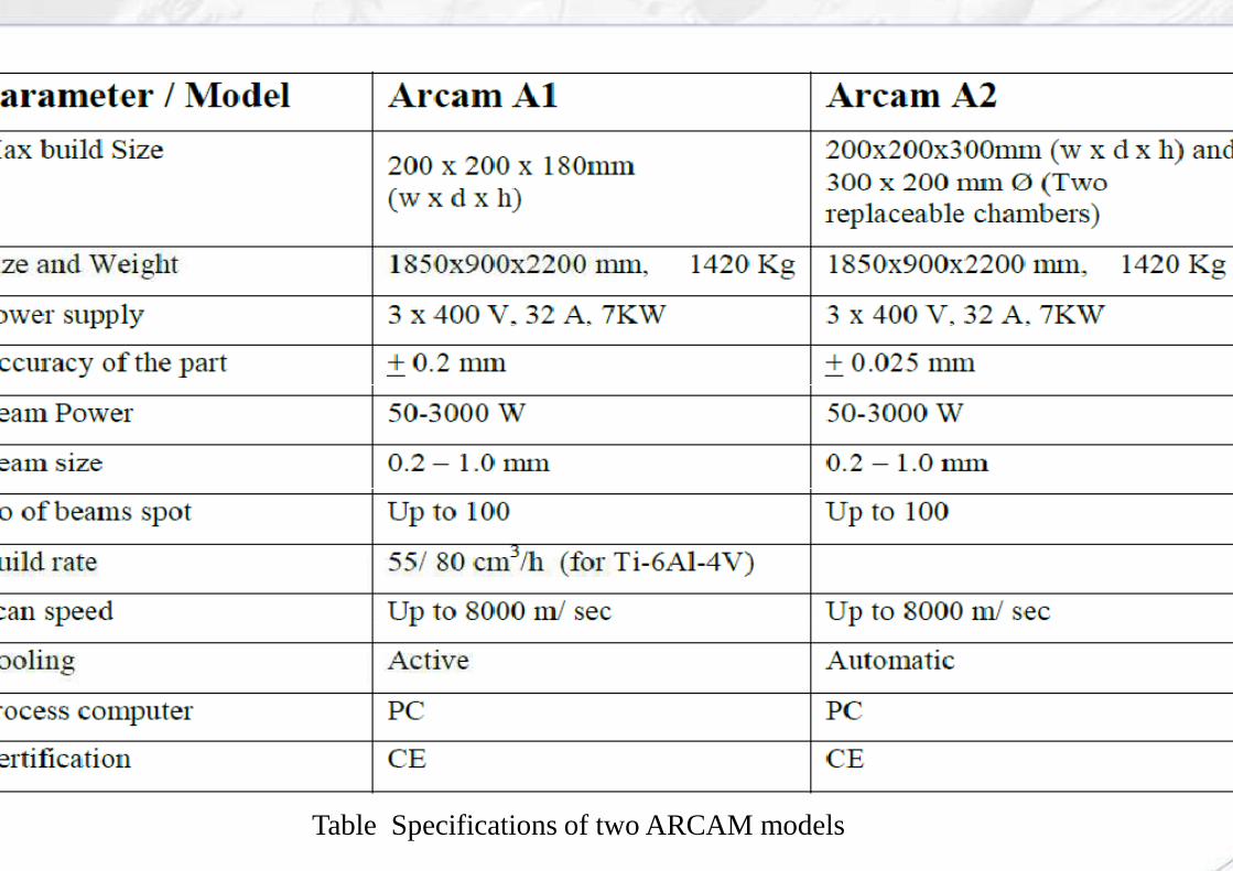
Rotor produced on an EOS ( Inconel 718 )
Size: Ø 140 x 80 mm
Rocket Engine Impeller ( Ti6Al4V )
Size: Ø 140 x 80 mmWeight: 2,5 kgBuild time: 16 hoursARCAM EBM
Thin walled turbine combustion chamber, produced on EOSINT M 270, material EOS Nickel Alloy IN 718
Swirler (fuel injection nozzle) for gas turbine applications made from Cobalt Chrome

Fig. Direct part manufactured by LENS deposition system ( Ti
Gas thruster – Bell helicopter
Dual wall exhaust duct
Fig. Direct part manufactured by LENS deposition system ( Ti-6Al-4V )
Gear box spider ( Red bull )

+ LENS
Conventional manufacturing cost -$3500
Manufacturing cost by LENS -$2000 Manufacturing cost by LENS -$2000
Wall thickness 7.6 mm
Fig.5. Ti-6Al-4V Small Ribbed Bracket ( Optomec )
$3500
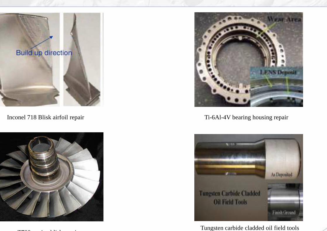
Inconel 718 Blisk airfoil repair
T700 engine blisk repair
Ti-6Al-4V bearing housing repair
Tungsten carbide cladded oil field tools

Defective forgings or castings can be repaired
Ti-6Al
Manufacturing defect repairing by deposition technologies
Laser repair ( LENS ) process is used
Fig. Repairing of undersized forgings
Defective forgings or castings can be repaired
6Al-4V atomizer drive plate ( Forging undersized )
Manufacturing defect repairing by deposition technologies
Laser repair ( LENS ) process is used
Fig. Repairing of undersized forgings

�
�
Hybrid Manufacturing by using deposition technologies
�
�
Fig. Ti-6Al-4V atomizer wheel with added boss
( Forging + additive manufacturing LENS )
Fig. Alloy 718 ring of GE aviation
Conventionnalmanufacturing + Additive manufacturing
Used for small feature addition ( flanges, pads, bosses )
Hybrid Manufacturing by using deposition technologies
Laser deposition based processes can be used
Initial raw material and machining cost can be saved
Fig. F119 fan section ( NASA )

Punch life before :
Punch life after :
Repairing cost :
Connecting rod punch ( after machining )
Repairing cost :
Lead time : 30 % less than new
Technical challenge : Severe wear and heat checking
H-13 and hard
Die after H13 deposition
H-13 and hard coating material deposited on forging die
Punch life before : 5000 cycles
Punch life after : 19,000 cycles
45 % of new
After deposition
45 % of new
30 % less than new
Severe wear and heat checking
13 and hard
Die after Nestelle C deposition
13 and hard coating material deposited on forging

Cost of 3D Printing
Complex bosses Cooled aerofoilsCooled aerofoils Internal cavities and oil ways
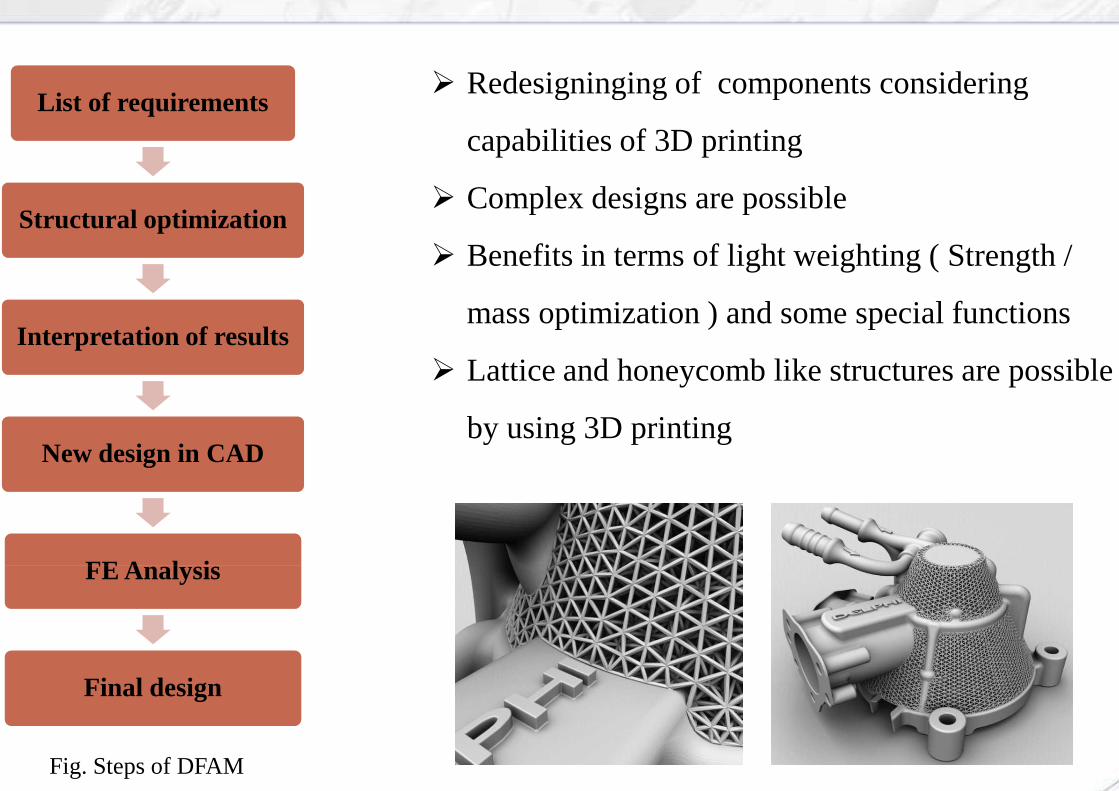
List of requirements
Structural optimization
� Redesigninging of components considering
capabilities of 3D printing
� Complex designs are possibleStructural optimization
Interpretation of results
New design in CAD
FE Analysis
� Benefits in terms of light weighting ( Strength /
mass optimization ) and some special functions
� Lattice and honeycomb like structures are possible
by using 3D printing
FE Analysis
Final design
Fig. Steps of DFAM
Redesigninging of components considering
capabilities of 3D printing
Complex designs are possible
Benefits in terms of light weighting ( Strength /
mass optimization ) and some special functions
Lattice and honeycomb like structures are possible
by using 3D printing
External lattice for heat dissipation

Design for additive manufacturing ( DFAM )
HC101 steel ( 7.7 gm/cm3 )918 gms
Ti64 alloy ( 4.42 gms/cm3 )326 gms

Design for additive manufacturing ( DFAM )
Mass : 870 gmsMaterial : Ti64
First class monitor arm
Mass : 285 gms
First class monitor arm
Mass : 370 gmsMaterial : Ti64Reduction : 57.4 %
Mass : 148 gmsReduction : 48 %

Material ProcessingTensile strength
( Mpa )
Wrought 950
Properties of 3D Printed metals
6Al-4VPowder bed /
deposited1100 / 1045
IN 718Wrought 1265
Powder bed / deposited
1241 / 1247
IN 625Wrought 965
Powder bed / 930 / 1052
Powder bed / deposited
930 / 1052
316 L-SS Wrought 585
Powder bed / deposited
625 / 678
Yield strength ( Mpa )
Elongation ( % )
Young's modulus( Gpa )
880 14 -
1000 / 1145 11 / 9 107 / 116
1075 18 -
1034 / 1088 18 / 21 170 / -
480 52 -
650 / 694 44 / 33 160 / -650 / 694 44 / 33 160 / -
380 45 193
525 / 515 ~ 43 ~177

Pre-processing 3D Printing
Pre and Post Processing Required
Reverse engg. Tools
Magics ( support editing ) Magics ( support editing )
software
Post-processing 3D Printing
�Support, part cutting
�Grinding, polishing
�Shot peening
�Heat treatment
�HIP treatment

Process: Simultaneous application of
hydrostatic pressure up to 500-1400 bar under
argon gas at temperatures between 400-1400
Application fields : Aerospace , defense , oil and gas, power generation, nuclear automotive
Benefits
Eliminates porosity in sintered parts
Removes fatigue crack initiation sites
Achieves homogeneous microstructure, eliminates
internal voids.
Typical tensile strength and ductility improvement is 5
% and upto 50 % respectively.
Achieves homogeneous microstructure, eliminates
Typical tensile strength and ductility improvement is 5
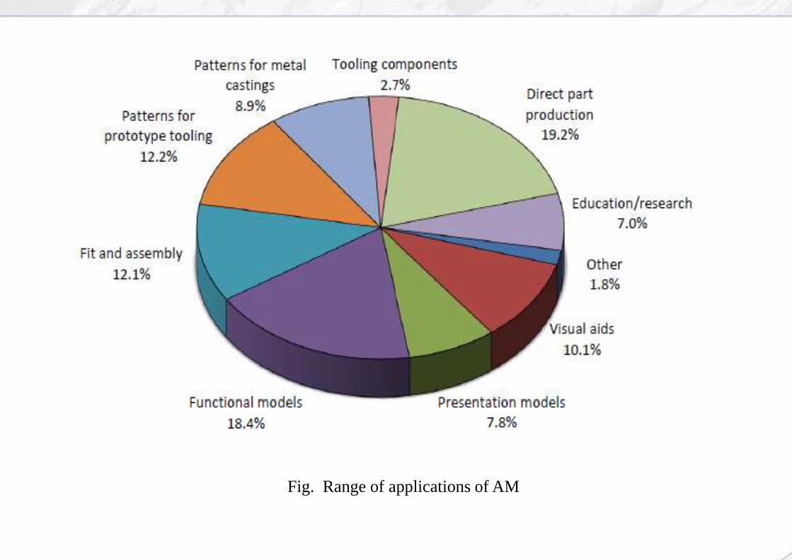
Applications of additive manufacturing
Fig. Range of applications of AMFig. Range of applications of AM

Fig. Metal powder bed type 3D systemsFig. Metal powder bed type 3D systems

Sr. no. Applications 3D systems market leaders
1. Polymer AM EOS ( Electro Optical Systems ), 3D systems
2. Tooling's EOS, Concept laser 2. Tooling's EOS, Concept laser
3. Dental EOS, Phoenix systems
4. Medical EOS, ARCAM, SLM Solutions
5. Aerospace EOS, RENISHAW, SLM Solutions, ARCAM
6. Auto EOS, SLM Solutions, RENISHAW, Concept laser6. Auto EOS, SLM Solutions, RENISHAW, Concept laser
7. Lifestyle EOS, Concept laser, Relizer
8. Repair LENS from Optomec and DMD from DM3D
3D systems market leaders
EOS ( Electro Optical Systems ), 3D systems
EOS, Concept laser EOS, Concept laser
EOS, Phoenix systems
EOS, ARCAM, SLM Solutions
EOS, RENISHAW, SLM Solutions, ARCAM
EOS, SLM Solutions, RENISHAW, Concept laserEOS, SLM Solutions, RENISHAW, Concept laser
EOS, Concept laser, Relizer
LENS from Optomec and DMD from DM3D

3D printing at GE and SAFRAN

�
Leap engine fuel nozzle
�
�
�
�
Fig. 3D printed LEAP fuel nozzle ( Cobalt-chromium alloy )
�Every LEAP engine has 19 fuel nozzles �Every LEAP engine has 19 fuel nozzles
( conventional nozzle is assembly of 20 parts )
�Single piece
�25 % lighter
�5 times durable than conventional

THANK YOUTHANK YOU
www.bharatforge.com
THANK YOUTHANK YOU
www.bharatforge.com