MOLDED CASE CIRCUIT BREAKERS - LSIS
24
Automation Equipment MOLDED CASE CIRCUIT BREAKERS UL listed MCCBs Leader in Electrics & Automation
Transcript of MOLDED CASE CIRCUIT BREAKERS - LSIS

Automation Equipment
MOLDED CASE CIRCUITBREAKERS
UL listed MCCBs
Leader in Electrics & Automation
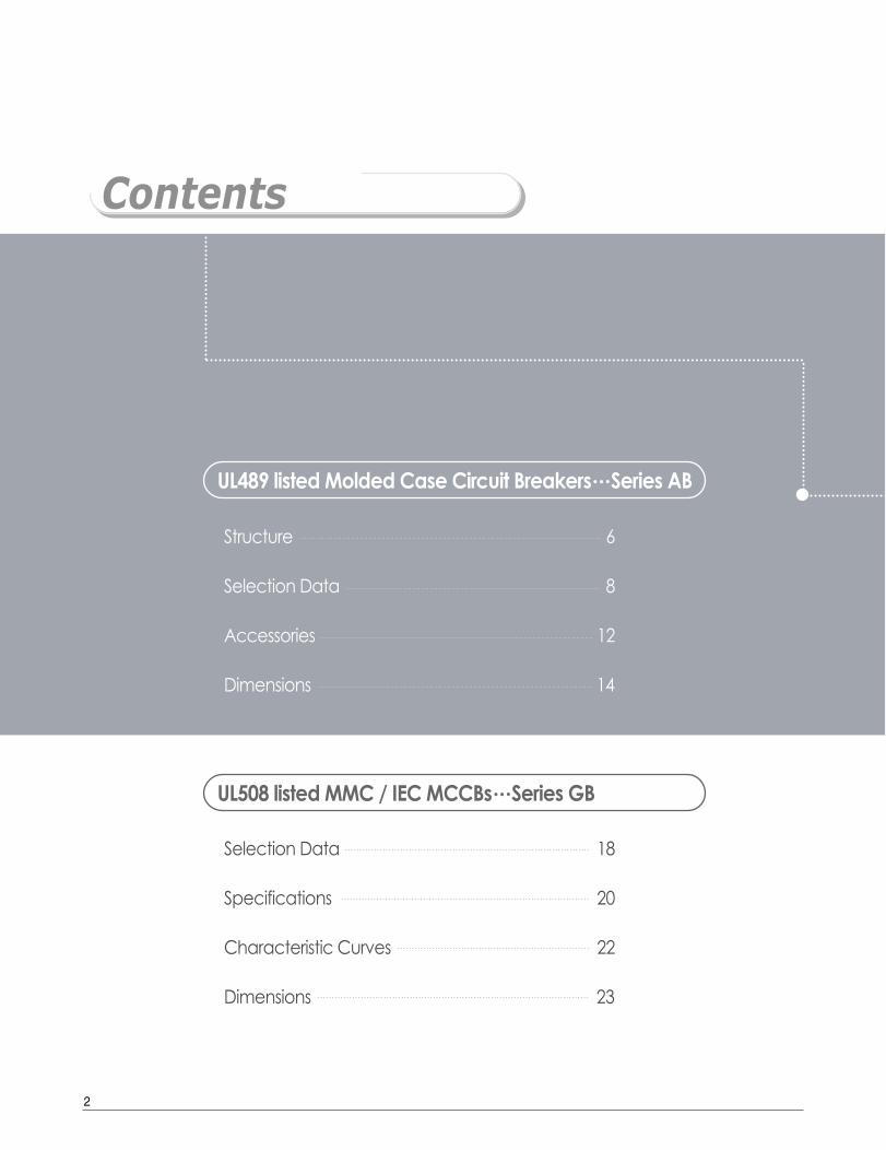
Contents
Structure 6
Selection Data 8
Accessories 12
Dimensions 14
UL489 listed Molded Case Circuit Breakers……Series AB
Selection Data 18
Specifications 20
Characteristic Curves 22
Dimensions 23
UL508 listed MMC / IEC MCCBs……Series GB
2
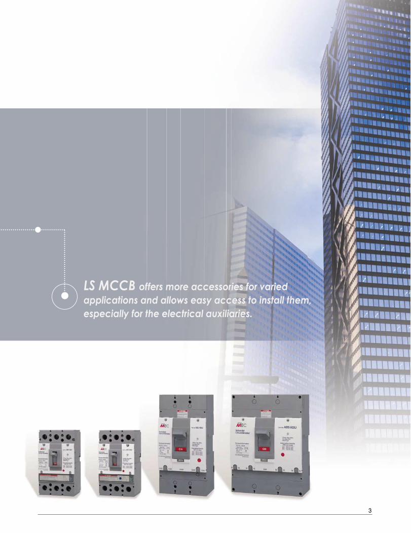
LS MCCB offers more accessories for varied applications and allows easy access to install them,especially for the electrical auxiliaries.
3

4
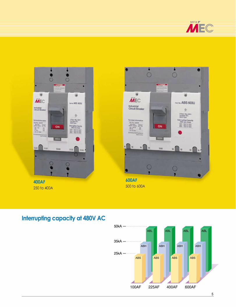
100AF / 225AF15 to 100A
225AF125 to 225A
Compact Design saves the SpaceInches(mm)
Width Height Depth
100AF4.13 7.28 3.39
225AF(105) (185) (86)
400AF5.51 11.02 4.33
(140) (280) (110)
600AF 8.27 11.02 4.33(210) (280) (110)
DW
H
Series ABUL489 listed Molded Case Circuit Breakers
5
100AF 225AF 400AF 600AF
ABL ABL ABL ABL
Interrupting capacity at 480V AC
400AF250 to 400A
600AF500 to 600A

Arc ExtinguishersArc extinguishers dissipate arcs thatresult when the circuit breakerinterrupts current flow.
Series ABStructure
11
11
22
33
44
55
66
HandleThe handle position clearly indicatesthe contact status: closed, open or tripped.The handle indicates "ON" for safetywhen the contacts are closed.
22
Auxiliary CoverAuxiliary cover provides convenience when accessories are installed and replaced.
33
Trip ButtonTrip button provides a manual means of exercising the mechanism by manually tripping the circuit breaker.
44 Operating MechanismOperating mechanism is to providea means of opening and closing thecircuit breaker.This mechanism is the quick-make,quick-break type and it is constructedso that all poles will make and breaksimultaneously when operated manually or automatically. This mechanism is also trip-free.
66
Trip UnitsThe function of the trip unit is to tripthe operating mechanism in theevent of a prolonged overloador short-circuit current.To accomplish this, thermal magnetic trip units are provided. Protection is provided by combininga temperature sensitive device with acurrent sensitive electromagnetic device.
55
6

Catalog Numbering System
Note ) - Position omitted if not used.
Breaker Type
ABN MCS
ABS 25kA
ABH 35kA
ABL 50kA
* by UL489 interruptingrating at 480Vac
Poles
2 2Poles
3 3Poles
Accessories
AX Auxiliary switch
AL Alarm switch
SHT Shunt trip
UVT Under voltage trip
MI Mech. Interlock
* See page 12~13
Rated Current
15A
20A
30A
100AF40A
50A
60A
80A
100A
125A
150A
225AF 175A
200A
225A
250A
400AF300A
350A
400A
600AF500A
600A
Ampere Frame
10 100AF
20 225AF
40 400AF
60 600AF
UL Listed
- -
U Listed
7
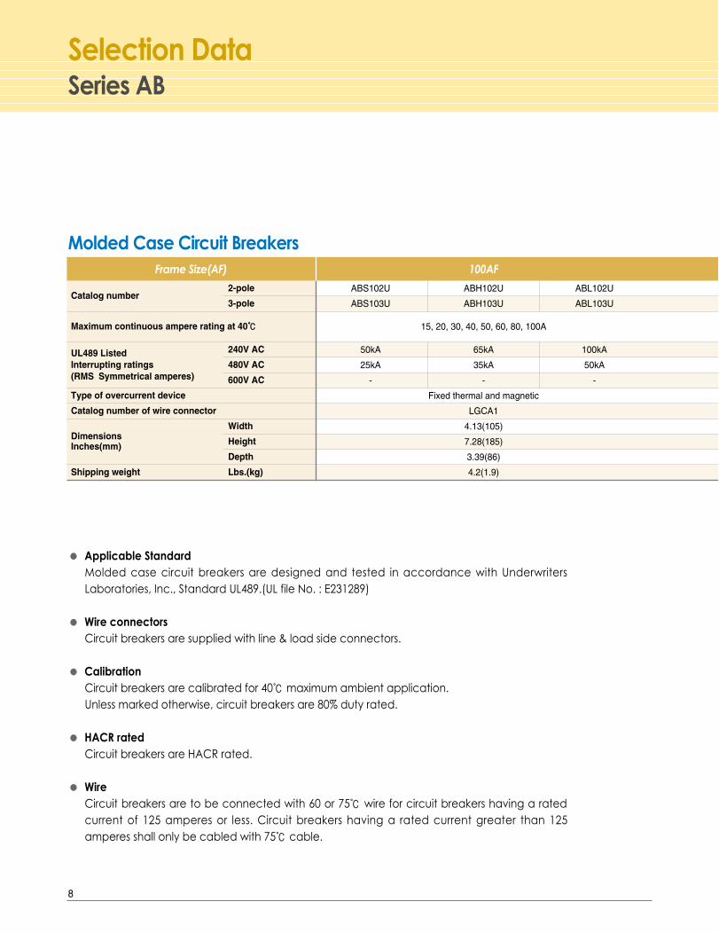
Series ABSelection Data
●● Applicable StandardMolded case circuit breakers are designed and tested in accordance with UnderwritersLaboratories, Inc., Standard UL489.(UL file No. : E231289)
●● Wire connectorsCircuit breakers are supplied with line & load side connectors.
●● CalibrationCircuit breakers are calibrated for 40℃maximum ambient application.Unless marked otherwise, circuit breakers are 80% duty rated.
●● HACR ratedCircuit breakers are HACR rated.
●● WireCircuit breakers are to be connected with 60 or 75℃ wire for circuit breakers having a ratedcurrent of 125 amperes or less. Circuit breakers having a rated current greater than 125amperes shall only be cabled with 75℃ cable.
Catalog number2-pole
3-pole
Maximum continuous ampere rating at 40℃℃
UL489 Listed 240V AC
Interrupting ratings 480V AC(RMS Symmetrical amperes) 600V AC
Type of overcurrent device
Catalog number of wire connector
DimensionsWidth
Inches(mm) Height
Depth
Shipping weight Lbs.(kg)
Frame Size(AF) 100AF
ABS102U ABH102U ABL102U
ABS103U ABH103U ABL103U
15, 20, 30, 40, 50, 60, 80, 100A
50kA 65kA 100kA
25kA 35kA 50kA
- - -
Fixed thermal and magnetic
LGCA1
4.13(105)
7.28(185)
3.39(86)
4.2(1.9)
Molded Case Circuit Breakers
8
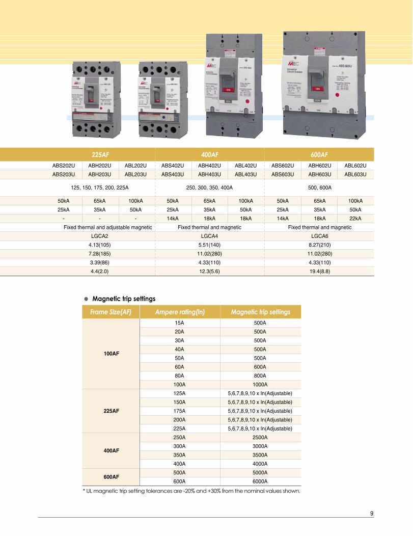
15A 500A
20A 500A
30A 500A
100AF40A 500A
50A 500A
60A 600A
80A 800A
100A 1000A
125A 5,6,7,8,9,10 x In(Adjustable)
150A 5,6,7,8,9,10 x In(Adjustable)
225AF 175A 5,6,7,8,9,10 x In(Adjustable)
200A 5,6,7,8,9,10 x In(Adjustable)
225A 5,6,7,8,9,10 x In(Adjustable)
250A 2500A
300A 3000A400AF
350A 3500A
400A 4000A
600AF500A 5000A
600A 6000A
Frame Size(AF) Ampere rating(In) Magnetic trip settings
* UL magnetic trip setting tolerances are -20% and +30% from the nominal values shown.
●● Magnetic trip settings
225AF 400AF 600AF
ABS202U ABH202U ABL202U ABS402U ABH402U ABL402U ABS602U ABH602U ABL602U
ABS203U ABH203U ABL203U ABS403U ABH403U ABL403U ABS603U ABH603U ABL603U
125, 150, 175, 200, 225A 250, 300, 350, 400A 500, 600A
50kA 65kA 100kA 50kA 65kA 100kA 50kA 65kA 100kA
25kA 35kA 50kA 25kA 35kA 50kA 25kA 35kA 50kA
- - - 14kA 18kA 18kA 14kA 18kA 22kA
Fixed thermal and adjustable magnetic Fixed thermal and magnetic Fixed thermal and magnetic
LGCA2 LGCA4 LGCA6
4.13(105) 5.51(140) 8.27(210)
7.28(185) 11.02(280) 11.02(280)
3.39(86) 4.33(110) 4.33(110)
4.4(2.0) 12.3(5.6) 19.4(8.8)
9

Series ABSelection Data
Catalog number
Poles
Maximum voltage ratings
Switch ampere ratings
240V AC
Short circuit withstand ratings 480V AC
600V AC
Catalog number of wire connector
Dimensions
Shipping weight
Frame Size(AF) 100AF 225AF 400AF 600AF
ABN103U ABN203U ABN403U ABN603U
3 3 3 3
480V AC 480V AC 600V AC 600V AC
30,60,100A 225A 400A 600A
100kA 100kA 100kA 100kA
50kA 50kA 50kA 50kA
- - 18kA 22kA
LGCA1 LGCA2 LGCA4 LGCA6
Same as MCCB
Same as MCCB
● Molded Case Switches are listed in accordance with Underwriters Laboratories, Inc., Standard UL489.(UL file No. : E223516)
● Molded Case Switches are calibrated to protect only the Molded Case Switch itself, when it issubjected to high fault currents.
● Molded Case Switches open instantaneously at a factory preset magnetic trip point and provide nooverload or low level fault protection.
● The short circuit withstand rating is the fault current at rated voltage that the molded case switch willwithstand without damage when protected by a circuit breaker with an equal continuous currentrating.
● Molded case switches are used as compact switches in applications requiring high current switchingcapabilities.
● All molded case switches will accept the same lugs and accessories as equivalent circuit breakers.
● Molded case switches open when the handle is switched to the OFF position or in response toauxiliary tripping device such as a shunt trip.
30A 500A
100AF 60A 600A
100A 1000A
225AF 225A 2250A
400AF 400A 4000A
600AF 600A 6000A
Frame Size(AF) Ampere rating Trip point
* UL magnetic trip setting tolerances are -20% and +30% from the nominal values shown.
Trip Point of MCS
Molded Case Switches
10

Catalog No.
LGCA1
LGCA2
LGCA4
LGCA6
Aluminumalloy
Aluminumalloy
Aluminumalloy
Aluminumalloy
Size(inches)Head Style
14 ~ 8 1 60(69)
6 ~ 1/0 1 80(92)
1 1 150(173)
1/0 ~ 2/0 1 180(207)
3/0 ~ 4/0 1 250(288)
250 ~ 300 1 325(374)
250 ~ 400 1 325(374)
500 1 375(432)
3/0 2 250(288)
250 ~ 400 2 325(374)
500 2 375(432)
Slotted Head7/16-20 UNF 2A
Hex. Head9/16-18UNF 2A
Hex. Head1-12
UNF 2A
Hex. Head5/8-18
UNF 2A
Lug information
● Lug terminals are listed in accordance with Underwriters Laboratories, Inc., Standard UL486A.
● Lug terminals are suitable for compact wires that CSA Standard (C22.2 No.65) require.
● Wire connectors intended for use with copper conductors only.
● Lug terminals are suitable for 60/75℃ wire.
Shape TerminalMaterial AWG,kcmil Number of
conductors
Wire range TighteningTorque
lb-in(kgf.cm)
Binding screw
11

Series ABAccessories
Auxiliary Switch, AX
Alarm Switch, AL
Shunt Trip, SHT
Auxiliary Switch, AX
Alarm Switch, AL
Shunt Trip, SHT
Under Voltage Trip, UVT
Under Voltage Trip, UVT
Electrical auxiliaries
Auxiliary Switch, AXSignals the status of the breaker - opening or closingConsists of one changeover switch per unit
- Compartments are accessible from the front by opening auxiliary cover.- Not necessary to take off the breaker cover.
Alarm Switch, ALSignals when a breaker is trippedConsists of one changeover switch
Right-handseat
Left-hand seat
100AF 225AF 400AF 600AF
AC/DC common 24/48/100~110/200~220V
AC 380~440V, 440~480V
Operational voltage 35~70% of rated volts
Re-close voltage of CB 85~110% of rated volts
Under voltage trip, UVTTrips a breaker when control voltage disappears or falls below the set value
100AF 225AF 400AF 600AF
24~48V
AC/DC common 12/24/48/60/250V AC200~240/DC200~220V
AC100~125/DC100~110V
100~125/200~240
AC 380~450/440~480 380~460/480~550V
500~550V
DC100~110/125/200~220
-240/250V
Operational 75~110% of rated volts 75~110% of rated voltsvoltage
Shunt trip, SHTTrips a breaker remotely
●100, 225AF breakers
Right-handseat
Left-hand seat
●400, 600AF breakers
AC
Max. switching
Operational current(A)
voltage(V) Resistive Inductive load load
125 5 3
250 3 2
DC
Max. switching
Operational current(A)
voltage(V) Resistive Inductive load load
30 4 3
125 0.4 0.4
250 0.2 0.2
Ratings of the AX & AL
12
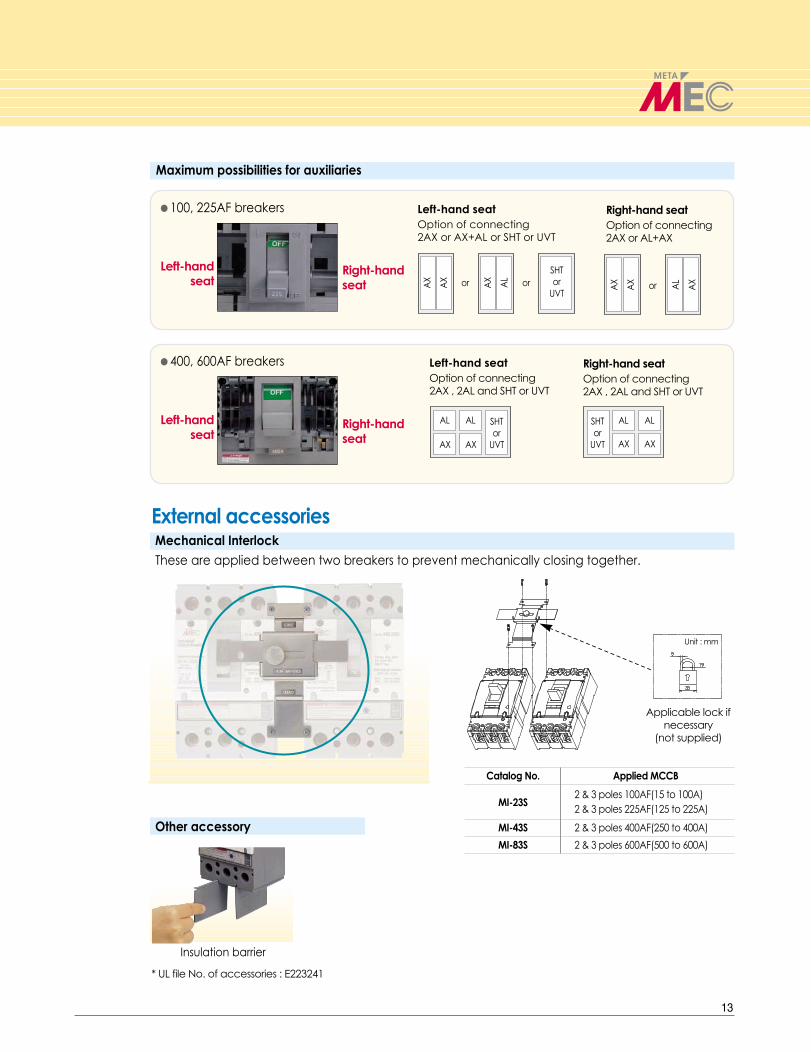
Maximum possibilities for auxiliaries
Right-hand seat
Left-hand seat
Left-hand seatOption of connecting 2AX or AX+AL or SHT or UVT
Right-hand seatOption of connecting 2AX or AL+AX
Right-hand seat
Left-hand seat
Left-hand seatOption of connecting 2AX , 2AL and SHT or UVT
Right-hand seatOption of connecting 2AX , 2AL and SHT or UVT
External accessoriesMechanical Interlock These are applied between two breakers to prevent mechanically closing together.
Other accessory
Applicable lock ifnecessary
(not supplied)
Unit : mm
Insulation barrier
Catalog No. Applied MCCB
MI-23S2 & 3 poles 100AF(15 to 100A)2 & 3 poles 225AF(125 to 225A)
MI-43S 2 & 3 poles 400AF(250 to 400A)
MI-83S 2 & 3 poles 600AF(500 to 600A)
●100, 225AF breakers
●400, 600AF breakers
* UL file No. of accessories : E223241
13
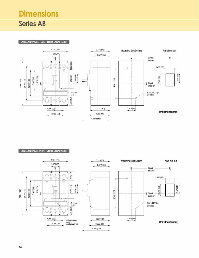
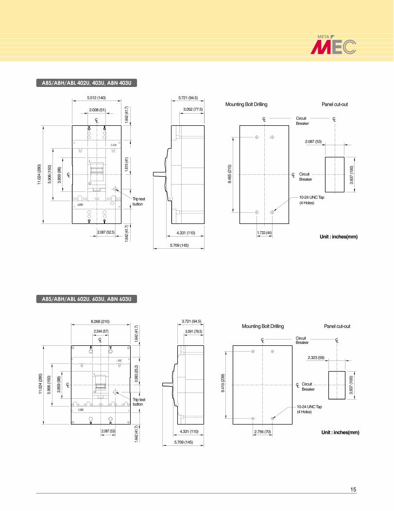
Series ABDimensions
Mounting Bolt Drilling Panel cut-out
Mounting Bolt Drilling Panel cut-out
2.756 (70)
1.378 (35)
2.756 (70)
1.378 (35)
4.96
1 (1
26)
1.457 (37)
2.04
8 (5
2)
Circuit Breaker
1.57
5 (4
0)
Circuit Breaker
8-32 UNC Tap(2 Holes)
0.82
7 (2
1)
C 1.53
6 (3
9)
Unit : Inches(mm)
L
CL
0.906 (23)
1.50
8 (3
8.3)
4.134 (105)
1.50
8 (3
8.3)
4.567 (116)
3.229 (82)
3.386 (86)
2.874 (73)
3.110 (79)
Trip test button
4.96
1 (1
26)
4.29
2 (1
09)
3.34
7 (8
5)
5.67
0 (1
44)
7.28
4 (1
85)
1.96
9 (5
0)
4.29
2 (1
09)
3.34
7 (8
5)
5.67
0 (1
44)
7.28
4 (1
85)
1.96
9 (5
0)
3.386 (86)
3.229 (82)
4.567 (116)
1.50
8 (3
8.3)
0.906 (23)
1.53
6 (3
9)
LC
0.82
7 (2
1)
Trip test button
4.134 (105)
1.378 (35)
LC
1.50
8 (3
8.3)
3.110 (79)
2.874 (73)
Unit : Inches(mm)
1.57
5 (4
0)1.457 (37)
(2 Holes)8-32 UNC Tap
Circuit Breaker
LC 2.04
8 (5
2)
Circuit Breaker
LC CL
Instantaneous currentregulating knob
1.378 (35)
CL
CL
CL
ABS/ABH/ABL 102U, 103U, ABN 103U
ABS/ABH/ABL 202U, 203U, ABN 203U
14
Mounting Bolt Drilling Panel cut-out
1.733 (44)8.
465
(215
)
2.008 (51)
5.512 (140)
5.90
6 (1
50)
11.0
24 (2
80)
2.087 (53)
3.93
7 (1
00)
3.85
9 (9
8)
1.64
2 (4
1.7)
3.721 (94.5)
3.052 (77.5)
1.64
2 (4
1.7)
2.067 (52.5)
1.61
5 (4
1)
4.331 (110)
5.709 (145)
Circuit Breaker
10-24 UNC Tap
Unit : inches(mm)
(4 Holes)
Circuit Breaker
Trip test button
Mounting Bolt Drilling Panel cut-out
9.41
0 (2
39)
2.323 (59)
3.93
7 (1
00)
3.721 (94.5)
3.091 (78.5)
10-24 UNC Tap(4 Holes)
2.756 (70)
8.268 (210)
1.64
2 (4
1.7)
1.64
2 (4
1.7)
3.85
9 (9
8)
5.90
6 (1
50)
11.0
24 (2
80)
2.087 (53)
2.244 (57)
0.99
3 (2
5.2)
4.331 (110)
5.709 (145)
Circuit Breaker
Circuit Breaker
Unit : inches(mm)
Trip test button
LC
LC
LC
LC
LC
LC
LC
LCLC
LC
ABS/ABH/ABL 402U, 403U, ABN 403U
ABS/ABH/ABL 602U, 603U, ABN 603U
15
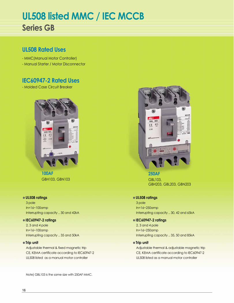
●UL508 ratings3 pole
In=16~250amp
Interrupting capacity .. 30, 42 and 65kA
●IEC60947-2 ratings2, 3 and 4 pole
In=16~250amp
Interrupting capacity .. 35, 50 and 85kA
●Trip unitAdjustable thermal & adjustable magnetic trip
CE, KEMA certificate according to IEC60947-2
UL508 listed as a manual motor controller
●UL508 ratings3 pole
In=16~100amp
Interrupting capacity .. 30 and 42kA
●IEC60947-2 ratings2, 3 and 4 pole
In=16~100amp
Interrupting capacity .. 35 and 50kA
●Trip unitAdjustable thermal & fixed magnetic trip
CE, KEMA certificate according to IEC60947-2
UL508 listed as a manual motor controller
Note) GBL103 is the same size with 250AF MMC.
UL508 Rated Uses- MMC(Manual Motor Controller)
- Manual Starter / Motor Disconnector
IEC60947-2 Rated Uses- Molded Case Circuit Breaker
Series GBUL508 listed MMC / IEC MCCB
100AFGBH103, GBN103
250AFGBL103, GBH203, GBL203, GBN203
16

Application according to UL508
Individual Installation
Group Installation
●CB : Circuit Breaker
●D/S : Disconnect Switch
●MC : Magnetic Contactor
●TOR : Thermal Overload Relay
●MMC : Manual Motor Controller
Regend
17

Series GBSelection Data
Catalog Numbering System
AccessoriesAuxiliary switch, AXAlarm switch, ALShunt trip unit, SHTUndervoltage Trip, UVT- See page 12~13
Rotary handleTerminal coverInsulation barrierRear connection kits
Manual Motor Controllers
Catalog number 3-pole
Maximum continuous ampere rating at 40℃℃, In
UL508 Listed 240V AC
Interrupting ratings 480V AC(RMS Symmetrical amperes) 600V AC
IEC60947-2 Rated 240V AC
ultimate breaking capacity 415V AC(RMS Symmetrical amperes) 600V AC
Type of overcurrent device
WidthDimensions
HeightInches(mm)
Depth
Shipping weight Lbs.(kg)
Frame Size(AF) 100AF 250AF
GBN103 GBH103 GBL103 GBN203 GBH203 GBL203
16, 20, 25, 32, 40, 50, 63, 80, 100A 125, 160, 200, 250AAdjustable 0.8/0.9/1.0xIn Adjustable 0.8/0.9/1.0xIn
30kA 42kA 65kA 30kA 42kA 65kA
50kA 85kA 125kA 50kA 85kA 125kA
35kA 50kA 85kA 35kA 50kA 85kA
18kA 25kA 35kA 18kA 25kA 35kA
Adjustable thermal and Adjustable thermal andfixed magnetic magnetic
3.5(90) 4.1(105) 4.1(105)
5.5(140) 6.5(165) 6.5(165)
3.4(86) 3.4(86) 3.4(86)
2.6(1.2) 3.7(1.7) 3.7(1.7)
Breaker Type
GBN 30kA
GBH 42kA
GBL 65kA
* by UL508 interruptingrating at 480Vac
Ampere Frame
10 100AF
20 250AF
Poles
2 2Poles
3 3Poles
Rated Current
16A
20A
25A
32A
100AF 40A
50A
63A
80A
100A
125A
160A250AF
200A
250A
18

Frame Size(AF) 100AF 250AF
Trip unit TMU16 TMU20 TMU25 TMU32 TMU40 TMU50 TMU63 TMU80 TMU100 TMU125 TMU160 TMU200 TMU250
Ranges 0.8×In 13 16 20 26 32 40 50 64 80 100 128 160 200
of the Ir 0.9×In 14 18 23 29 36 45 57 72 90 113 144 180 225
1.0×In 16 20 25 32 40 50 63 80 100 125 160 200 250
Ranges of the Im 500A 10×In 5, 6, 7, 8, 9, 10×In
① Rated current regulating knob, Ir3 steps : 0.8 / 0.9 / 1.0 x In
② Instantaneous current regulating knob, Im● Fixed instantaneous current type (100AF)
: 10 x In (Min. 500A)● Adjustable instantaneous current type (250AF)
: 5 / 6 / 7 / 8 / 9/ 10 x In (6 steps)
Thermal & Magnetic trip● TMU type (Thermal-magnetic trip unit)
100 Amp. Frame
250 Amp. Frame
① ②
Interrupting ratings●●According to UL508
GBN → 30kA
GBH → 42kA
GBL → 65kA at AC480V
●According to IEC 60947-2GBN → 35kA
GBH → 50kA
GBL → 85kA at AC415V
In : Rated current Ir : Ajustable
thermal currentIm : Instantaneous
current
(Adjustable thermal & Fixed magnetic)
(Adjustable thermal & Adjustable magnetic)
①
②
①
19
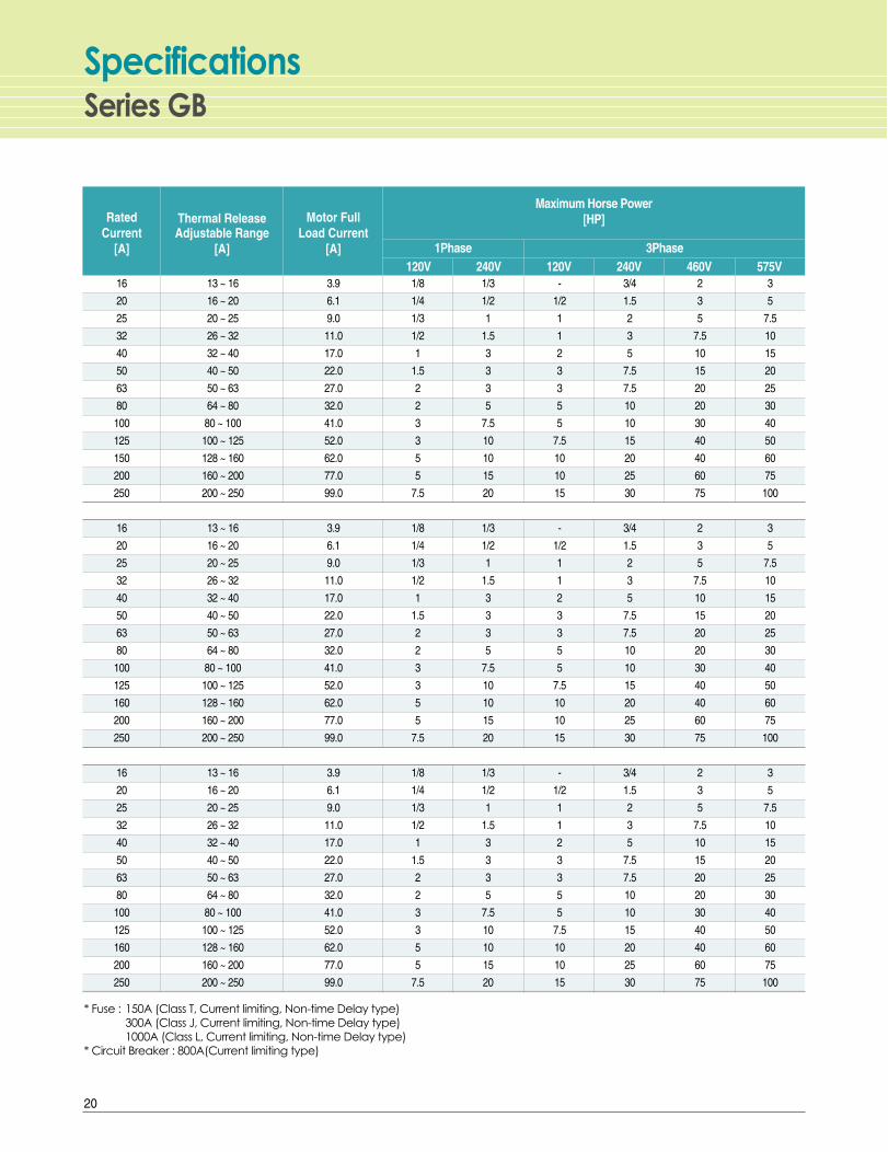
Series GBSpecifications
Rated Current
[A]
* Fuse : 150A (Class T, Current limiting, Non-time Delay type)300A (Class J, Current limiting, Non-time Delay type)1000A (Class L, Current limiting, Non-time Delay type)
* Circuit Breaker : 800A(Current limiting type)
Thermal Release Adjustable Range
[A]
Motor Full Load Current
[A] 1Phase120V 240V 120V 240V 460V 575V
3Phase
Maximum Horse Power[HP]
16
20
25
32
40
50
63
80
100
125
150
200
250
16
20
25
32
40
50
63
80
100
125
160
200
250
16
20
25
32
40
50
63
80
100
125
160
200
250
13 ~ 16
16 ~ 20
20 ~ 25
26 ~ 32
32 ~ 40
40 ~ 50
50 ~ 63
64 ~ 80
80 ~ 100
100 ~ 125
128 ~ 160
160 ~ 200
200 ~ 250
13 ~ 16
16 ~ 20
20 ~ 25
26 ~ 32
32 ~ 40
40 ~ 50
50 ~ 63
64 ~ 80
80 ~ 100
100 ~ 125
128 ~ 160
160 ~ 200
200 ~ 250
13 ~ 16
16 ~ 20
20 ~ 25
26 ~ 32
32 ~ 40
40 ~ 50
50 ~ 63
64 ~ 80
80 ~ 100
100 ~ 125
128 ~ 160
160 ~ 200
200 ~ 250
3.9
6.1
9.0
11.0
17.0
22.0
27.0
32.0
41.0
52.0
62.0
77.0
99.0
3.9
6.1
9.0
11.0
17.0
22.0
27.0
32.0
41.0
52.0
62.0
77.0
99.0
3.9
6.1
9.0
11.0
17.0
22.0
27.0
32.0
41.0
52.0
62.0
77.0
99.0
1/8
1/4
1/3
1/2
1
1.5
2
2
3
3
5
5
7.5
1/8
1/4
1/3
1/2
1
1.5
2
2
3
3
5
5
7.5
1/8
1/4
1/3
1/2
1
1.5
2
2
3
3
5
5
7.5
1/3
1/2
1
1.5
3
3
3
5
7.5
10
10
15
20
1/3
1/2
1
1.5
3
3
3
5
7.5
10
10
15
20
1/3
1/2
1
1.5
3
3
3
5
7.5
10
10
15
20
-
1/2
1
1
2
3
3
5
5
7.5
10
10
15
-
1/2
1
1
2
3
3
5
5
7.5
10
10
15
-
1/2
1
1
2
3
3
5
5
7.5
10
10
15
3/4
1.5
2
3
5
7.5
7.5
10
10
15
20
25
30
3/4
1.5
2
3
5
7.5
7.5
10
10
15
20
25
30
3/4
1.5
2
3
5
7.5
7.5
10
10
15
20
25
30
2
3
5
7.5
10
15
20
20
30
40
40
60
75
2
3
5
7.5
10
15
20
20
30
40
40
60
75
2
3
5
7.5
10
15
20
20
30
40
40
60
75
3
5
7.5
10
15
20
25
30
40
50
60
75
100
3
5
7.5
10
15
20
25
30
40
50
60
75
100
3
5
7.5
10
15
20
25
30
40
50
60
75
100
20

* UL File No. : E214031 (UL508/As a Manual Motor Controller)
600V Max. 480V Max. 600V Max. 480V Max.Single Motor
Max. Backup ProtectionGroup Motor
Fuse [A] ShortCircuit
Fuse [A] Fuse [A] ShortCircuit
CB [A]
Catalog No.
ShortCircuit
CB [A] Fuse [A] ShortCircuit
150
150
150
150
150
150
150
150
150
300
300
300
300
150
150
150
150
150
150
150
150
150
300
300
300
300
150
150
150
150
150
150
150
150
150
300
300
300
300
5kA
5kA
5kA
5kA
5kA
5kA
5kA
5kA
5kA
10kA
10kA
10kA
10kA
5kA
5kA
5kA
5kA
5kA
5kA
5kA
5kA
5kA
10kA
10kA
10kA
10kA
5kA
5kA
5kA
5kA
5kA
5kA
5kA
5kA
5kA
10kA
10kA
10kA
10kA
150
150
150
150
150
150
150
150
150
300
300
300
300
150
150
150
150
150
150
150
150
150
300
300
300
300
150
150
150
150
150
150
150
150
150
300
300
300
300
30kA
30kA
30kA
30kA
30kA
30kA
30kA
30kA
30kA
30kA
30kA
30kA
30kA
42kA
42kA
42kA
42kA
42kA
42kA
42kA
42kA
42kA
42kA
42kA
42kA
42kA
65kA
65kA
65kA
65kA
65kA
65kA
65kA
65kA
65kA
65kA
65kA
65kA
65kA
1000
1000
1000
1000
1000
1000
1000
1000
1000
1000
1000
1000
1000
1000
1000
1000
1000
1000
1000
1000
1000
1000
1000
1000
1000
1000
1000
1000
1000
1000
1000
1000
1000
1000
1000
1000
1000
1000
1000
800
800
800
800
800
800
800
800
800
800
800
800
800
800
800
800
800
800
800
800
800
800
800
800
800
800
800
800
800
800
800
800
800
800
800
800
800
800
800
5kA
5kA
5kA
5kA
5kA
5kA
5kA
5kA
5kA
10kA
10kA
10kA
10kA
5kA
5kA
5kA
5kA
5kA
5kA
5kA
5kA
5kA
10kA
10kA
10kA
10kA
5kA
5kA
5kA
5kA
5kA
5kA
5kA
5kA
5kA
10kA
10kA
10kA
10kA
1000
1000
1000
1000
1000
1000
1000
1000
1000
1000
1000
1000
1000
1000
1000
1000
1000
1000
1000
1000
1000
1000
1000
1000
1000
1000
1000
1000
1000
1000
1000
1000
1000
1000
1000
1000
1000
1000
1000
800
800
800
800
800
800
800
800
800
800
800
800
800
800
800
800
800
800
800
800
800
800
800
800
800
800
800
800
800
800
800
800
800
800
800
800
800
800
800
30kA
30kA
30kA
30kA
30kA
30kA
30kA
30kA
30kA
30kA
30kA
30kA
30kA
42kA
42kA
42kA
42kA
42kA
42kA
42kA
42kA
42kA
42kA
42kA
42kA
42kA
65kA
65kA
65kA
65kA
65kA
65kA
65kA
65kA
65kA
65kA
65kA
65kA
65kA
GBN103 16A
GBN103 20A
GBN103 25A
GBN103 32A
GBN103 40A
GBN103 50A
GBN103 63A
GBN103 80A
GBN103 100A
GBN203 125A
GBN203 160A
GBN203 200A
GBN203 250A
GBH103 16A
GBH103 20A
GBH103 25A
GBH103 32A
GBH103 40A
GBH103 50A
GBH103 63A
GBH103 80A
GBH103 100A
GBH203 125A
GBH203 160A
GBH203 200A
GBH203 250A
GBL103 16A
GBL103 20A
GBL103 25A
GBL103 32A
GBL103 40A
GBL103 50A
GBL103 63A
GBL103 80A
GBL103 100A
GBL203 125A
GBL203 160A
GBL203 200A
GBL203 250A
21
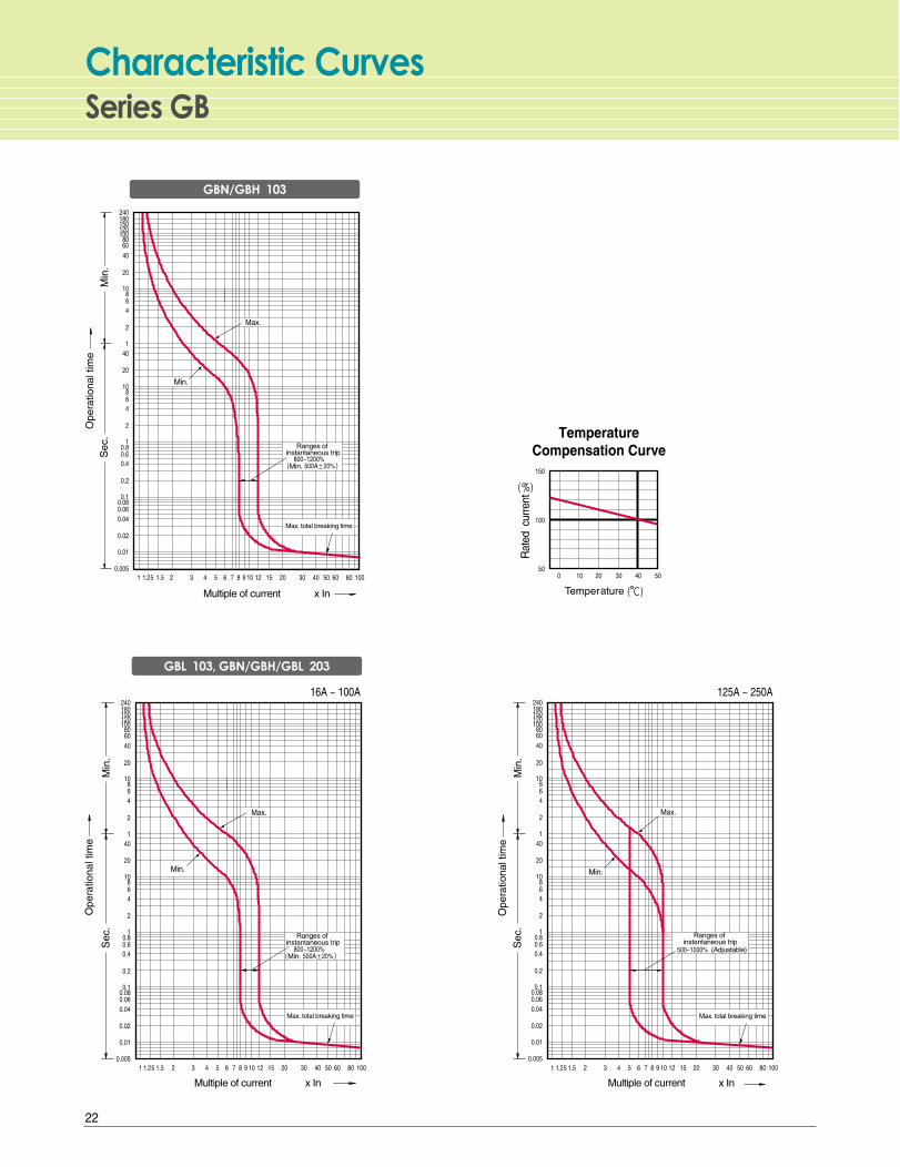
Series GBCharacteristic Curves
Temperature Compensation Curve
GBN/GBH 103
GBL 103, GBN/GBH/GBL 203
22
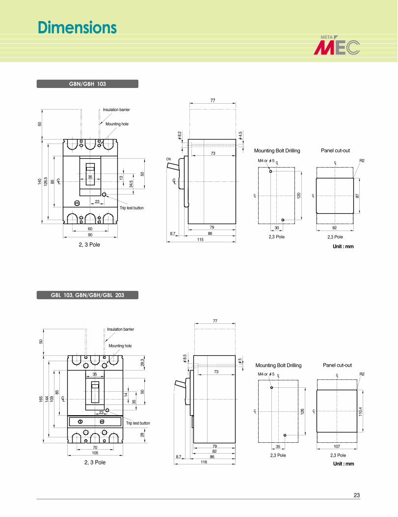
Dimensions
Unit : mm
Unit : mm
5014
012
6.5
85
5016
514
4
85
14
35
28
8.7 868279
116
5028
.3
109
Mounting Bolt Drilling Panel cut-out
Mounting Bolt Drilling Panel cut-out
23
13
50
ф8.
2
120
87
ф4.
5
73
30 92
ф8.
5
ф5
M4 or ф5 R273
35 107
126
110.
4
77
79
86
115
8.7
34.5
60
35
70105
90
35
23
M4 or ф5 R2
GBN/GBH 103
GBL 103, GBN/GBH/GBL 203
23
www.lsis.biz
�� For your safety, please read user's manual thoroughly before operating.
�� Contact the nearest authorized service facility for examination, repair, or adjustment.
�� Please contact a qualified service technician when you need maintenance.Do not disassemble or repair by yourself!
�� Any maintenance and inspection shall be performed by the personnel having expertise concerned.Safety Instructions
UL listed MCCBs 2002. 1/(09) 2007. 09 Printed in Korea STAFF2007. 09
Leader in Electrics & Automation
��LS Industrial Systems Tokyo Office JapanAddress: 16F, Higashi-Kan, Akasaka Twin Towers 17-22, 2-chome,Akasaka, Minato-ku Tokyo 107-8470, JapanTel: 81-3-3582-9128 Fax: 81-3-3582-0065 e-mail: [email protected]��LS Industrial Systems Dubai Office UAE
Address: P.O.Box-114216, API World Tower, 303B, Sheikh Zayed road, Dubai, UAE.Tel: 971-4-3328289 Fax: 971-4-3329444 e-mail: [email protected]��LS-VINA Industrial Systems Co., Ltd Vietnam
Address: LSIS VINA Congty che tao may dien Viet-Hung Dong Anh Hanoi, VietnamTel: 84-4-882-0222 Fax: 84-4-882-0220 e-mail: [email protected]��LS Industrial Systems Hanoi Office Vietnam
Address: Room C21, 5Th Floor, Horison Hotel, 40 Cat Linh , Hanoi, VietnamTel: 84-4-736-6270/1 Fax: 84-4-736-6269��Dalian LS Industrial Systems Co., Ltd China
Address: No. 15 Liaohexi 3 Road, economic and technical development zone, Dalian, ChinaTel: 86-411-8731-8210 Fax: 86-411-8730-7560 e-mail: [email protected]��LS Industrial Trading (Shanghai) Co., Ltd China
Address: Room 1705-1707, 17th Floor Xinda Commercial Building No 322, Xian Xia Road Shanahai, ChinaTel: 86-21-6252-4291 Fax: 86-21-6278-4372 e-mail: [email protected]��LS Industrial Systems Beijing Office China
Address: Room 303, 3F North B/D, EAS 21 XIAO YUN ROAD,Dong San Huan Bei Road, Chao Yang District, Beijing, ChinaTel: 86-10-6462-3259/4 Fax: 86-10-6462-3236 e-mail: [email protected]��LS Industrial Systems Shanghai Office China
Address: Room 1705-1707, 17th Floor Xinda Commercial BuildingNo 318, Xian Xia Road Shanahai, ChinaTel: 86-21-6278-4370 Fax: 86-21-6278-4301 e-mail: [email protected]��LS Industrial Systems Guangzhou Office China
Address: Room 303, 3F, Zheng Sheng Building, No 5-6, Tian He Bei Road, Guangzhou, ChinaTel: 86-20-8755-3410 Fax: 86-20-8755-3408 e-mail: [email protected]
�� Global Network
Specifications in this catalog are subject to change without notice due to continuous product development and improvement.
�� HEAD OFFICEYonsei Jaedan Severance Bldg. 84-11, 5ga, Namdaemun-ro,
Jung-gu, Seoul 100-753, Korea
Tel. (82-2)2034-4870 Fax. (82-2)2034-4713
http://www.lsis.biz
�� CHEONG-JU PLANTCheong-Ju Plant #1, Song Jung Dong, Hung Duk Ku,
Cheong Ju, 361-720, Korea
Tel. (82-43)261-6001 Fax. (82-43)261-6410