Smart Molded Case Circuit Breakers
12
1. Overview • Susol MCCB Overview ........................................................... 2. Features • Susol MCCB features ............................................................ 3. Model selecting guide • Susol MCCB model numbering (Product selection) ................... 4. External structure and notation ............................................ 5. Rated specifications ............................................................ 6. Smart Trip Unit .................................................................... 42 44 48 50 52 56 Susol Smart MCCB Susol Smart MCCB is developed by combining digital technology with LS ELECTRIC's power device technology accumulated over 40 years. The relay and measurement functions for line protection has been upgraded. By using accessory devices for connectivity between low-voltage devices, it is possible to diagnose and maintain devices by collecting and analyzing data. Smart Molded Case Circuit Breakers
Transcript of Smart Molded Case Circuit Breakers
Smart LV Solution
1. Overview
• Susol MCCB Overview ...........................................................
2. Features
• Susol MCCB features ............................................................
3. Model selecting guide
• Susol MCCB model numbering (Product selection) ...................
4. External structure and notation ............................................
5. Rated specifications ............................................................
6. Smart Trip Unit ....................................................................
42
44
48
50
52
56
Susol Smart MCCB
Susol Smart MCCB is developed by combining digital technology with LS ELECTRIC's power device technology
accumulated over 40 years. The relay and measurement functions for line protection has been upgraded.
By using accessory devices for connectivity between low-voltage devices,
it is possible to diagnose and maintain devices by collecting and analyzing data.
Smart Molded Case Circuit Breakers
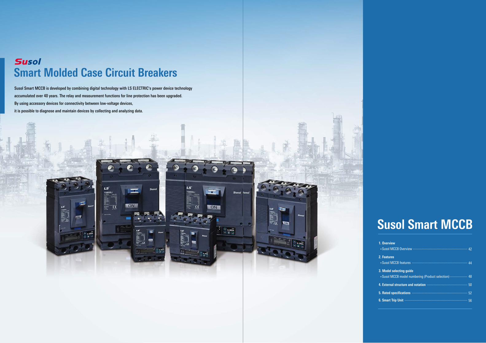
Super performanceThe third breaking performance guarantees
the original performance.
TS400L/Li TS400H/Hi TS400N/Ni
TS250L/Li TS250H/Hi TS250N/Ni
TS160L/LiTD160L
TS160H/HiTD160H
TS160N/NiTD160N
TS100L/LiTD100L
TS100H/HiTD100H
TS100N/NiTD100N
TS800L/Li TS800H/Hi TS800N/Ni
TS630L/Li TS630H/Hi TS630N/Ni
TS1600L TS1600HTS1250HTS1000H
TS1600NTS1250NTS1000N
(AF)
Breaking capacity, Icu(kA)
100A160A
250A400A
630A800A
1600A
Rated current, I
n(A)
150kA100kA85kA70kA65kA50kA
5 FramesIcs=100% Icu : 50, 65, 85, 100, 150kA at 415Vac
Rated current : 700, 800AIcu : 65kA (N/Ni), 100kA (H/Hi), 150kA (L/Li)Ics = Icu210 (W) × 320 (H) × 135mm (D)
TS800TS400/630
TS100/160/250 Rated current : 300~630AIcu : 65kA (N/Ni), 85kA (H/Hi), 150kA (L/Li)Ics = Icu140 (W) × 260 (H) × 110mm (D)Rated current : 40~250A
Icu : 50kA (N/Ni), 85kA (H/Hi), 150kA (L/Li)Ics = Icu105 (W) × 160 (H) × 86mm (D)
TD100/160Rated current : 16~160AIcu : 50kA (N), 85kA (H), 150kA (L)Ics = Icu90 (W) × 140 (H) × 86mm (D)
Rated current : 1000, 1250, 1600AIcu : 50kA (N), 70kA (H), 150kA (L)Ics = Icu210 (W) × 327 (H) × 152.5mm (D)
TS1600
42
Smart LV Solution
43
Susol Smart MCCBSusol MCCB Overview
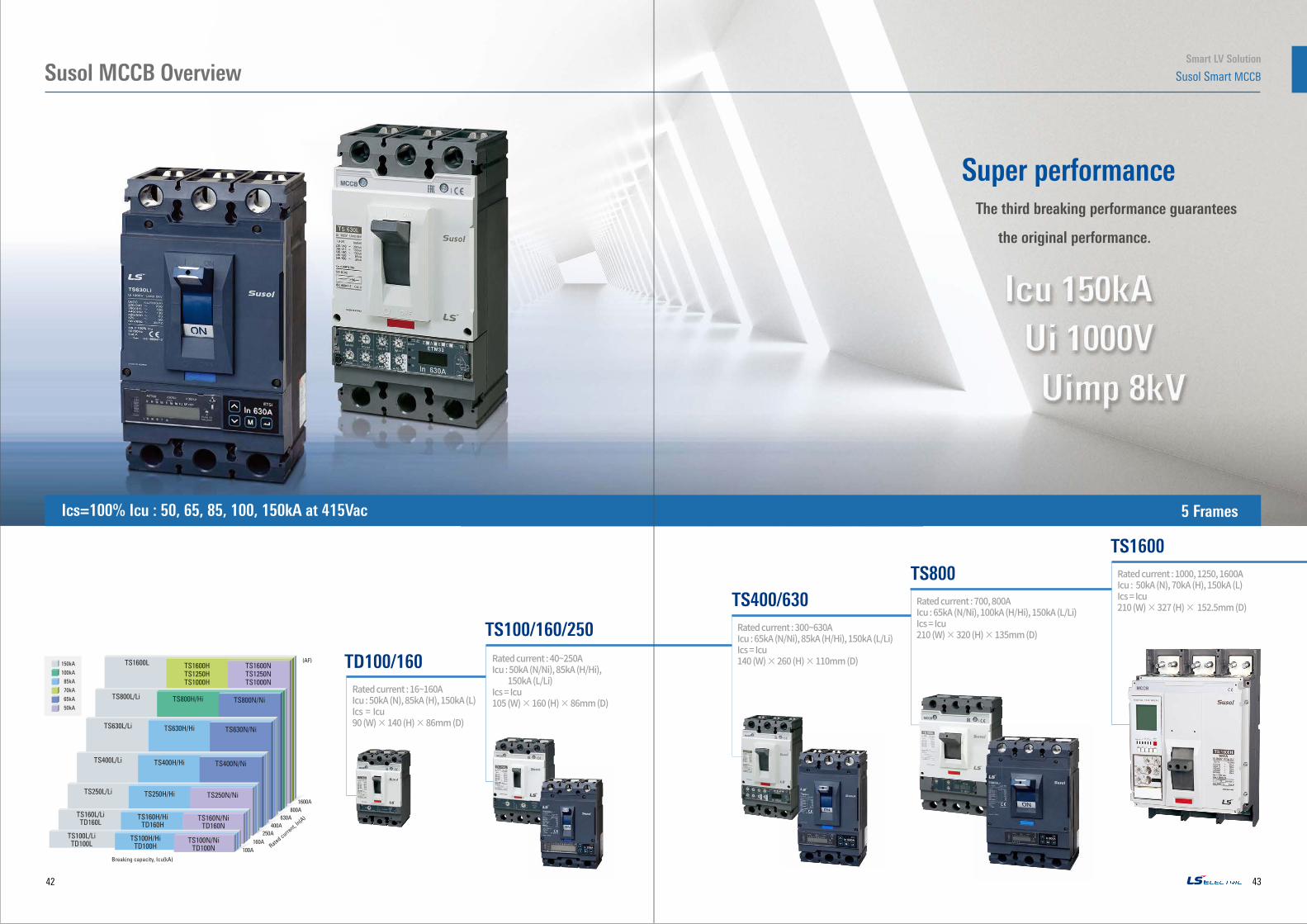
2. Electronic trip units- ETS/ ETSi : Standard- ETM/ ETMi : Multi-Function- ETHi : High-Performance- ETLi : Limited-Performance
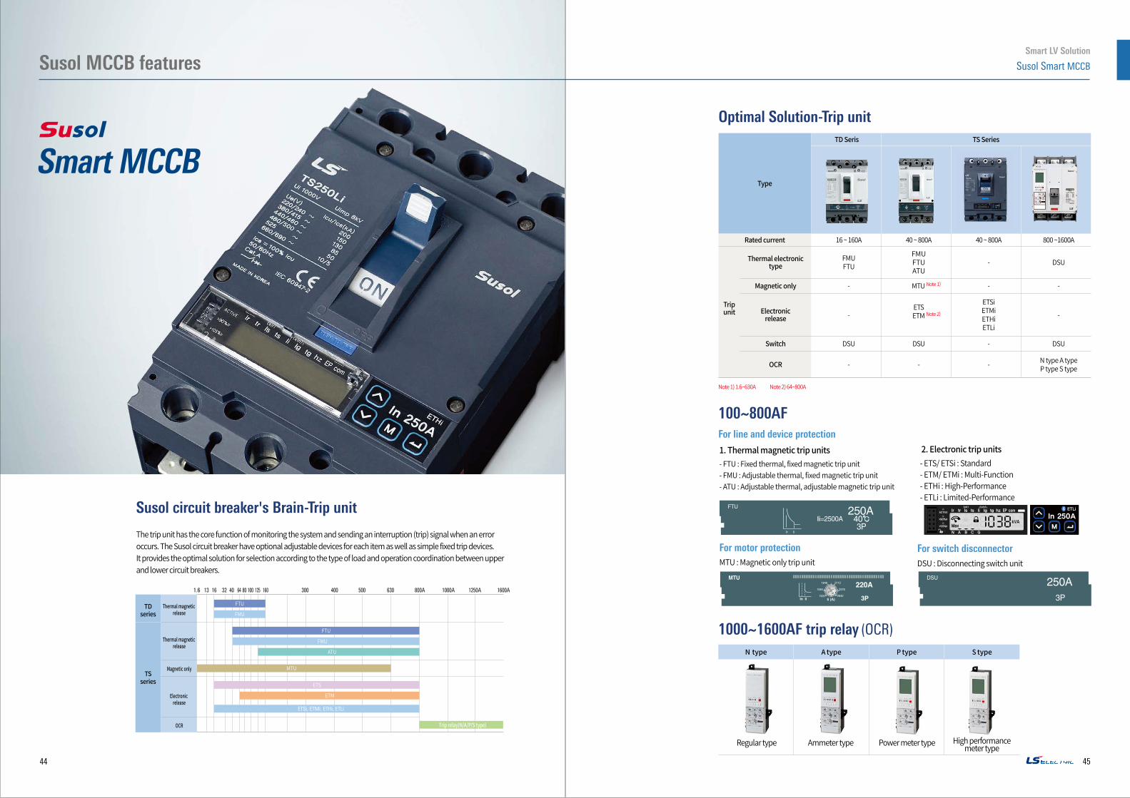
Susol circuit breaker's Brain-Trip unit
The trip unit has the core function of monitoring the system and sending an interruption (trip) signal when an error occurs. The Susol circuit breaker have optional adjustable devices for each item as well as simple fixed trip devices. It provides the optimal solution for selection according to the type of load and operation coordination between upper and lower circuit breakers.
Thermal magnetic release
Thermal magnetic release
Magnetic only
Electronic release
OCR
Optimal Solution-Trip unit
100~800AF
Type
TD Seris TS Series
Rated current 16 ~ 160A 40 ~ 800A 40 ~ 800A 800 ~1600A
Trip unit
Thermal electronic type
FMUFTU
FMUFTUATU
- DSU
Magnetic only - MTU Note 1) - -
Electronic release -
ETS ETM Note 2)
ETSiETMiETHiETLi
-
Switch DSU DSU - DSU
OCR - - - N type A typeP type S type
Note 1) 1.6~630A Note 2) 64~800A
1. Thermal magnetic trip units- FTU : Fixed thermal, fixed magnetic trip unit- FMU : Adjustable thermal, fixed magnetic trip unit- ATU : Adjustable thermal, adjustable magnetic trip unit
For motor protection MTU : Magnetic only trip unit
MTU220A3P
1848 2112
2376
2640
1584
1320
For switch disconnectorDSU : Disconnecting switch unit
DSU
3P
1000~1600AF trip relay (OCR)N type A type P type S type
Regular type Ammeter type Power meter type High performance meter type
Smart MCCB
For line and device protection
44
Smart LV Solution
45
Susol MCCB features Susol Smart MCCB
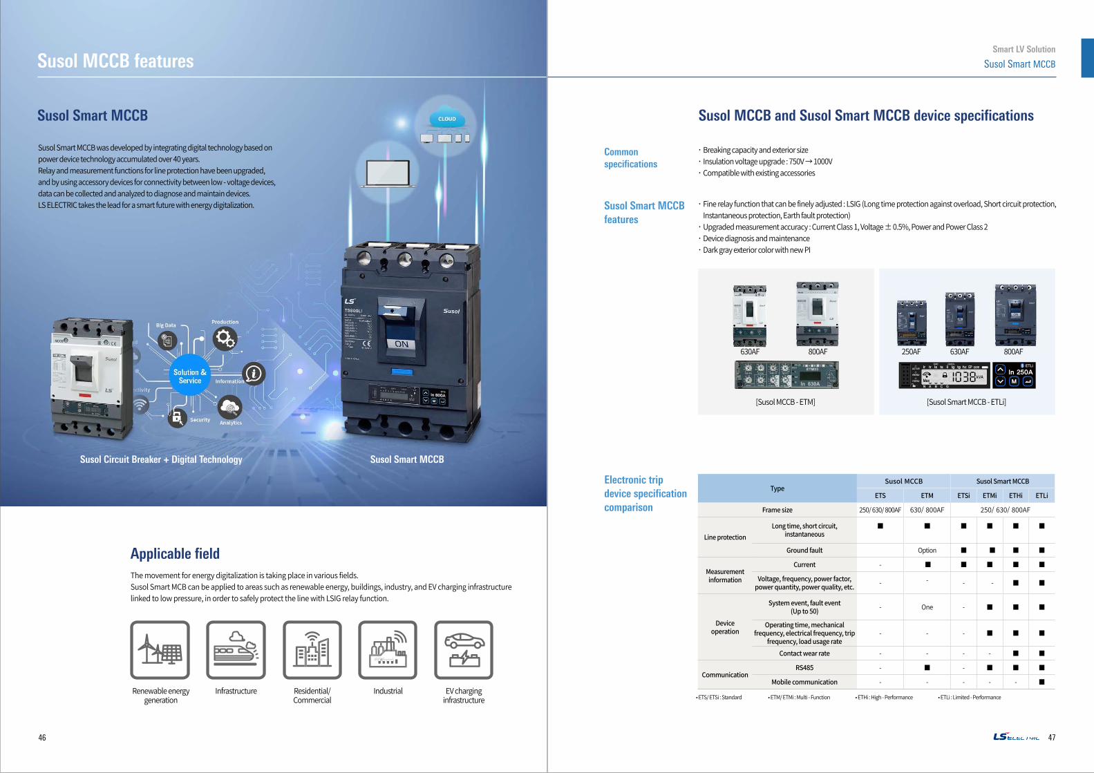
TypeSusol MCCB Susol Smart MCCB
ETS ETM ETSi ETMi ETHi ETLi
Frame size 250/ 630/ 800AF 630/ 800AF 250/ 630/ 800AF
Line protectionLong time, short circuit,
instantaneous■ ■ ■ ■ ■ ■
Ground fault Option ■ ■ ■ ■
Measurement information
Current - ■ ■ ■ ■ ■
Voltage, frequency, power factor, power quantity, power quality, etc. - - - - ■ ■
Device operation
System event, fault event(Up to 50) - One - ■ ■ ■
Operating time, mechanical frequency, electrical frequency, trip
frequency, load usage rate- - - ■ ■ ■
Contact wear rate - - - - ■ ■
CommunicationRS485 - ■ - ■ ■ ■
Mobile communication - - - - - ■
Susol Smart MCCB was developed by integrating digital technology based on power device technology accumulated over 40 years.Relay and measurement functions for line protection have been upgraded, and by using accessory devices for connectivity between low - voltage devices, data can be collected and analyzed to diagnose and maintain devices.LS ELECTRIC takes the lead for a smart future with energy digitalization.
The movement for energy digitalization is taking place in various fields.Susol Smart MCB can be applied to areas such as renewable energy, buildings, industry, and EV charging infrastructure linked to low pressure, in order to safely protect the line with LSIG relay function.
Susol Smart MCCB
Applicable field
Renewable energy generation
Residential/Commercial
Industrial EV charging infrastructure
Common specifications
Susol Smart MCCBfeatures
‧ Fine relay function that can be finely adjusted : LSIG (Long time protection against overload, Short circuit protection, Instantaneous protection, Earth fault protection)
‧Upgraded measurement accuracy : Current Class 1, Voltage ± 0.5%, Power and Power Class 2‧Device diagnosis and maintenance‧Dark gray exterior color with new PI
Susol MCCB and Susol Smart MCCB device specifications
• ETS/ ETSi : Standard • ETM/ ETMi : Multi - Function • ETHi : High - Performance • ETLi : Limited - Performance
630AF
[Susol MCCB - ETM]
800AF
[Susol Smart MCCB - ETLi]
250AF 800AF630AF
Electronic trip device specification comparison
Susol Circuit Breaker + Digital Technology Susol Smart MCCB
Infrastructure
‧Breaking capacity and exterior size‧Insulation voltage upgrade : 750V → 1000V‧Compatible with existing accessories
46
Smart LV Solution
47
Susol MCCB features Susol Smart MCCB
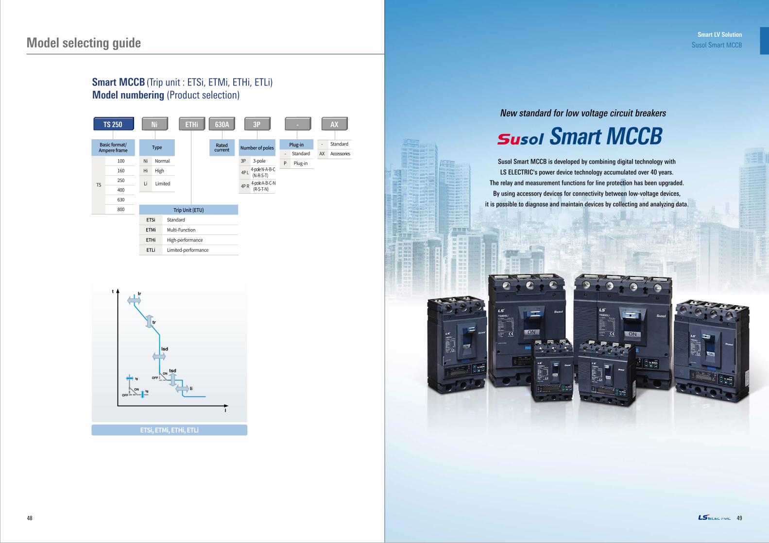
Smart MCCB (Trip unit : ETSi, ETMi, ETHi, ETLi) Model numbering (Product selection)
Type Number of polesRated current
TS 250 Ni -ETHi 630A 3P AX
3P 3-pole - Standard
P Plug-in
- Standard
AX Accessories
Trip Unit (ETU)
ETSi Standard
ETMi Multi-Function
ETHi High-performance
ETLi Limited-performance
Plug-in
ETSi, ETMi, ETHi, ETLi
Basic format/Ampere frame
100
160
TS
250
400
630
800
New standard for low voltage circuit breakers
Smart MCCB Ni Normal
Hi High
Li
Limited
Susol Smart MCCB is developed by combining digital technology with
LS ELECTRIC's power device technology accumulated over 40 years.
The relay and measurement functions for line protection has been upgraded.
By using accessory devices for connectivity between low-voltage devices,
it is possible to diagnose and maintain devices by collecting and analyzing data.
4P L 4-pole N-A-B-C (N-R-S-T)
4P R 4-pole A-B-C-N (R-S-T-N)
48
Susol Smart MCCB
49
Smart LV Solution
Model selecting guide
Ni
Hi
Li
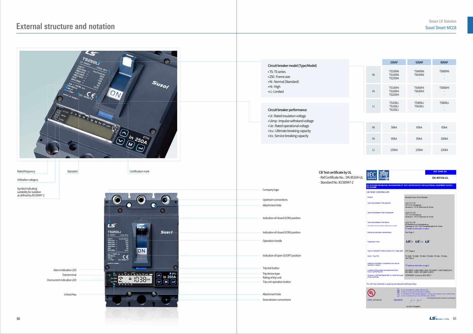
250AF
TS100NiTS160NiTS250Ni
TS100HiTS160HiTS250Hi
TS100LiTS160LiTS250Li
630AF
TS400NiTS630Ni
-
TS400HiTS630Hi
-
TS400LiTS630Li
-
800AF
TS800Ni--
TS800Hi--
TS800Li--
Ni 50kA 65kA 65kA
Hi 85kA 85kA 100kA
Li 150kA 150kA 150kA
Rated frequency Standard Certification mark
Symbol indicating suitability for isolation as defined by IEC60947-2
Utilization category
Circuit breaker model (Type/Model)• TS: TS series• 250 : Frame size• Ni : Normal (Standard)• Hi : High• Li : Limited
Circuit breaker performance• Ui : Rated insulation voltage• Uimp : Impulse withstand voltage• Ue : Rated operational voltage• Icu : Ultimate breaking capacity• Ics : Service breaking capacity
CB Test certificate by UL· Ref.Certificate No. : DK-85164-UL· Standard No. IEC60947-2
Company logo
Upstream connections
Attachment Hole
Indication of closed (I/ON) position
Indication of closed (I/ON) position
Operation handle
Indication of open (O/OFF) position
Trip test button
Trip unit operation button
Attachment hole
Trip device typeRating of trip unit
Downstream connections
Unlock Key
Alarm Indication LEDTest terminal
Overcurrent indication LED
50
Smart LV Solution
51
Susol Smart MCCBExternal structure and notation
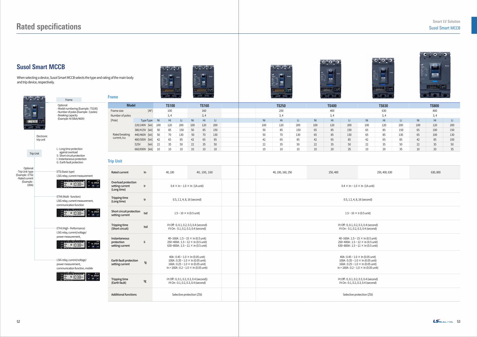
ETSi (basic type)LSIG relay, current measurement
ETMi (Multi - function) LSIG relay, current measurement, communication function
ETHi (High - Performance)LSIG relay, current/voltage/power measurement, communication function
LSIG relay, current/voltage/power measurement, communication function, mobile communication
Optional- Trip Unit type
(Example : ETSi)- Rated current
(Example : 100A)
Optional- Model numbering (Example : TS100)- Number of poles (Example : 3 poles)- Breaking capacity (Example: Ni 50kA/460V)
Trip Unit
Frame
Electronic trip unit
L : Long time protection against overload
S : Short circuit protectionI : Instantaneous protectionG : Earth fault protection
When selecting a device, Susol Smart MCCB selects the type and rating of the main body and trip device, respectively.
Frame
Model Frame size [AF]Number of poles [Pole] Type 220/240V [kA]
380/415V [kA]
440/460V [kA] 480/500V [kA] 525V [kA] 660/690V [kA]
TS250 TS400 TS630 TS800TS100 TS160
Trip Unit
Type
100 160 3, 4 3, 4 Ni Hi Li Ni Hi Li 100 120 200 100 120 200 50 85 150 50 85 150 50 70 130 50 70 130 42 65 85 42 65 85 22 35 50 22 35 50 10 10 10 10 10 10
250 400 3, 4 3, 4 Ni Hi Li Ni Hi Li 100 120 200 100 120 200 50 85 150 65 85 150 50 70 130 65 85 130 42 65 85 42 65 85 22 35 50 22 35 50 10 10 10 10 20 35
630 800 3, 4 3, 4 Ni Hi Li Ni Hi Li 100 120 200 100 120 200 65 85 150 65 100 150 65 85 130 65 100 130 42 65 85 42 85 100 22 35 50 22 35 50 10 20 35 10 20 35
Rated current In 40, 100 40, 100, 160 40, 100, 160, 250 250, 400 250, 400, 630 630, 800
Overload protection setting current(Long time)
Ir 0.4 × In ~ 1.0 × In (1A unit) 0.4 × In ~ 1.0 × In (1A unit)
Tripping time(Long time) tr 0.5, 1 2, 4, 8, 16 (second) 0.5, 1 2, 4, 8, 16 (second)
Short circuit protectionsetting current Isd 1.5 ~ 10 × Ir (0.5 unit) 1.5 ~ 10 × Ir (0.5 unit)
Tripping time(Short circuit) tsd I2t Off : 0, 0.1, 0.2, 0.3, 0.4 (second)
I2t On : 0.1, 0.2, 0.3, 0.4 (second)I2t Off : 0, 0.1, 0.2, 0.3, 0.4 (second)I2t On : 0.1, 0.2, 0.3, 0.4 (second)
Instantaneous protection setting current
Ii40~160A : 1.5 ~ 15 × In (0.5 unit)250~400A : 1.5 ~ 12 × In (0.5 unit)630~800A : 1.5 ~ 11 × In (0.5 unit)
40~160A : 1.5 ~ 15 × In (0.5 unit)250~400A : 1.5 ~ 12 × In (0.5 unit)630~800A : 1.5 ~ 11 × In (0.5 unit)
Earth fault protectionsetting current Ig
40A : 0.45 ~ 1.0 × In (0.05 unit)100A : 0.35 ~ 1.0 × In (0.05 unit)160A : 0.25 ~ 1.0 × In (0.05 unit)
In > 160A : 0.2 ~ 1.0 × In (0.05 unit)
40A : 0.45 ~ 1.0 × In (0.05 unit)100A : 0.35 ~ 1.0 × In (0.05 unit)160A : 0.25 ~ 1.0 × In (0.05 unit)
In > 160A : 0.2 ~ 1.0 × In (0.05 unit)
Tripping time(Earth fault) tg I2t Off : 0, 0.1, 0.2, 0.3, 0.4 (second))
I2t On : 0.1, 0.2, 0.3, 0.4 (second)I2t Off : 0, 0.1, 0.2, 0.3, 0.4 (second)I2t On : 0.1, 0.2, 0.3, 0.4 (second)
Additional functions Selective protection (ZSI) Selective protection (ZSI)
Susol Smart MCCB
Rated breaking current, Icu
ETSi
ETMi
ETHi
ETSi
ETMi
ETHi
ETSi
ETMi
ETHi
52
Smart LV Solution
53
Susol Smart MCCBRated specifications
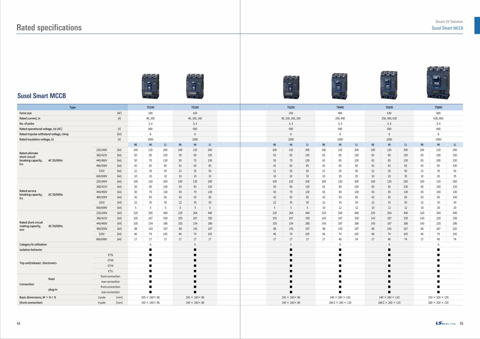
Type TS100 TS160 TS250 TS400 TS630 TS800
Fame size [AF] 100 160 250 400 630 800Rated current, In [A] 40, 100 40, 100, 160 40, 100, 160, 250 250, 400 250, 400, 630 630, 800No. of poles 3, 4 3, 4 3, 4 3, 4 3, 4 3, 4Rated operational voltage, Ue [AC] [V] 690 690 690 690 690 690Rated impulse withstand voltage, Uimp [kV] 8 8 8 8 8 8Rated insulation voltage, Ui [V] 1000 1000 1000 1000 1000 1000
Rated ultimate short-ciucuit breaking capacity, Icu
AC 50/60Hz
Ni Hi Li Ni Hi Li Ni Hi Li Ni Hi Li Ni Hi Li Ni Hi Li220/240V [kA] 100 120 200 100 120 200 100 120 200 100 120 200 100 120 200 100 120 200380/415V [kA] 50 85 150 50 85 150 50 85 150 65 85 150 65 85 150 65 100 150440/460V [kA] 50 70 130 50 70 130 50 70 130 65 85 130 65 85 130 65 100 130480/500V [kA] 42 65 85 42 65 85 42 65 85 42 65 85 42 65 85 42 85 100
525V [kA] 22 35 50 22 35 50 22 35 50 22 35 50 22 35 50 22 35 50660/690V [kA] 10 10 10 10 10 10 10 20 35 10 20 35 10 20 35 10 20 35
Rated service breaking capacity, Ics
AC 50/60Hz
220/240V [kA] 100 120 200 100 120 200 100 120 200 100 120 200 100 120 200 100 120 200380/415V [kA] 50 85 150 50 85 150 50 85 150 65 85 150 65 85 150 65 100 150440/460V [kA] 50 70 130 50 70 130 50 70 130 65 85 130 65 85 130 65 100 130480/500V [kA] 42 65 85 42 65 85 42 65 85 42 65 85 42 65 85 42 85 100
525V [kA] 22 35 50 22 35 50 22 35 50 22 35 50 22 35 50 22 35 50660/690V [kA] 5 5 5 5 5 5 5 5 5 10 12 12 10 12 12 10 20 20
Rated short-circuit making capacity, Icm
AC 50/60Hz
220/240V [kA] 220 265 440 220 264 440 220 264 440 220 264 440 220 264 440 220 264 440380/415V [kA] 105 187 330 105 187 330 105 187 330 143 187 330 143 187 330 143 220 330440/460V [kA] 105 154 286 105 154 286 105 154 286 143 187 286 143 187 286 143 220 286480/500V [kA] 88 143 187 88 143 187 88 143 187 88 143 187 88 143 187 88 187 220
525V [kA] 46 74 105 46 74 105 46 74 105 46 74 105 46 74 105 46 74 105660/690V [kA] 17 17 17 17 17 17 17 17 17 17 40 74 17 40 74 17 40 74
Category fo utilization A A A A A AIsolation behavior ■ ■ ■ ■ ■ ■
Trip unit(release) : Electronics
ETSi ■ ■ ■ ■ ■ ■ETMi ■ ■ ■ ■ ■ ■
ETHi ■ ■ ■ ■ ■ ■ETLi ■ ■ ■ ■ ■ ■
Connectionfixed
front-connection ■ ■ ■ ■ ■ ■rear-connection ■ ■ ■ ■ ■ ■
plug-infront-connection ■ ■ ■ ■ ■ ■rear-connection ■ ■ ■ ■ ■ ■
Basic dimensions, W × H× D 3-pole [mm] 105 × 160× 86 105 × 160× 86 105 × 160× 86 140 × 260 × 110 140 × 260 × 110 210 × 320 × 135(front-connection) 4-pole [mm] 140 × 160× 86 140 × 160× 86 140 × 160× 86 186.5 × 260 × 110 186.5 × 260 × 110 280 × 320 × 135
Susol Smart MCCB
54
Smart LV Solution
Susol Smart MCCB
55
Rated specifications
ETSi
ETMi
ETHi
ETSi
ETMi
ETHi
ETSi
ETMi
ETHi
Smart Trip Unit - ETSi, ETMi, ETHi, ETLi (Electronic)
Trip Unit Rated current
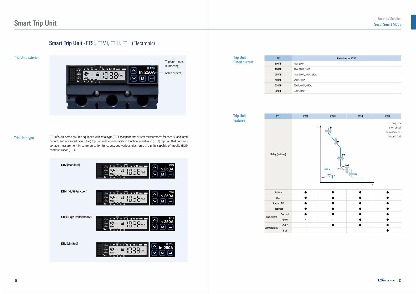
Trip Unit exterior
Trip Unit features
Trip Unit type ETU of Susol Smart MCCB is equipped with basic type (ETSi) that performs current measurement for each AF and rated current, and advanced type (ETMi) trip unit with communication function, a high-end (ETHi) trip unit that performs voltage measurement in communication functions, and various electronic trip units capable of mobile (BLE) communication (ETLi).
Trip Unit model numbering
Rated current
AF Rated current250
100AF 40A, 100A
160AF 40A, 100A, 160A
250AF 40A, 100A, 160A, 250A
400AF 250A, 400A
630AF 250A, 400A, 630A
800AF 630A, 800A
ETU ETSi ETMi ETHi ETLi
Relay (setting)
Button ● ● ● ●
LCD ● ● ● ●
Status LED ● ● ● ●
Test Port ● ● ● ●
MeasurementCurrent ● ● ● ●
Power - - ● ●
CommunicationRS485 - ● ● ●
BLE - - - ●
Long timeShort circuit
InstantaneousGround fault
ETSi (Standard)
ETMi (Multi-Function)
ETHi (High-Performance)
ETLi (Limited)
56
Smart LV Solution
Susol Smart MCCB
57
Smart Trip Unit
Smart Trip Unit - ETSi, ETMi, ETHi, ETLi (Electronic)
Overcurrent protection relay
Relay specification table
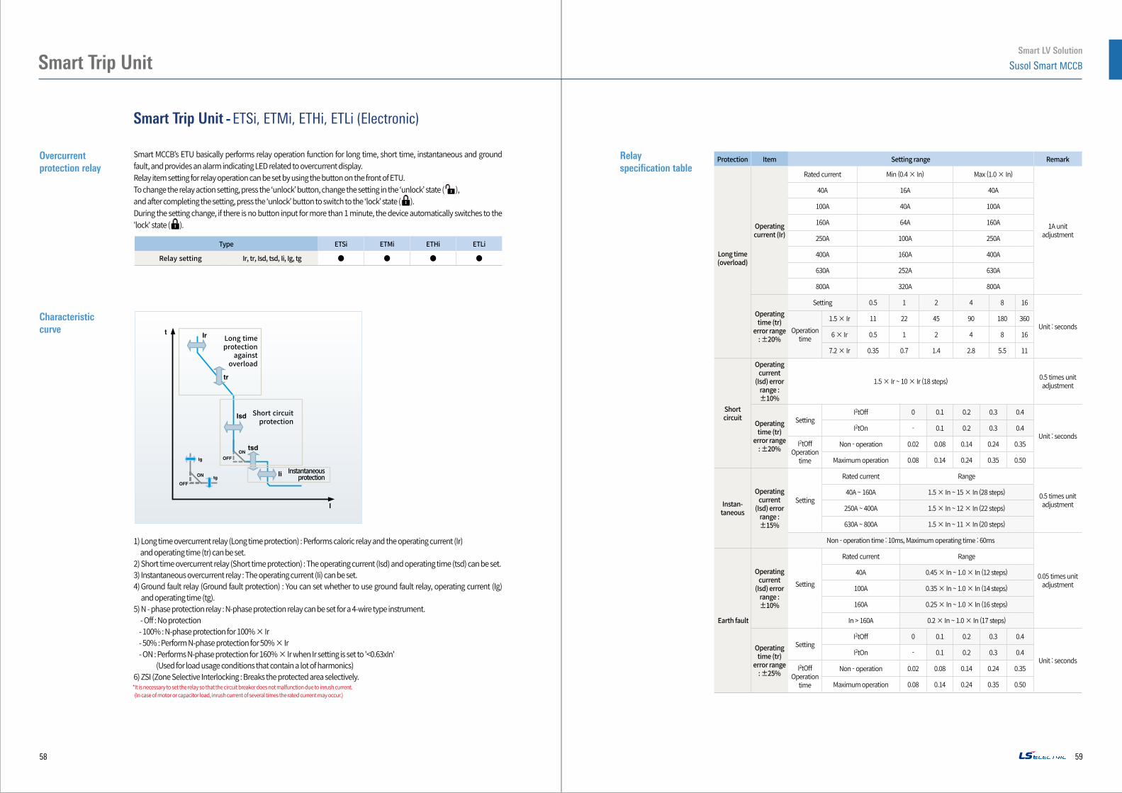
Smart MCCB’s ETU basically performs relay operation function for long time, short time, instantaneous and ground fault, and provides an alarm indicating LED related to overcurrent display.Relay item setting for relay operation can be set by using the button on the front of ETU.To change the relay action setting, press the ‘unlock’ button, change the setting in the ‘unlock’ state ( ), and after completing the setting, press the ‘unlock’ button to switch to the ‘lock’ state (To change the relay action setting, press the ‘unlock’ button, change the setting in the ‘unlock’ state (
).During the setting change, if there is no button input for more than 1 minute, the device automatically switches to the 'lock' state (During the setting change, if there is no button input for more than 1 minute, the device automatically switches to the
).
Type ETSi ETMi ETHi ETLi
Relay setting Ir, tr, Isd, tsd, Ii, Ig, tg ● ● ● ●
1) Long time overcurrent relay (Long time protection) : Performs caloric relay and the operating current (Ir) and operating time (tr) can be set.2) Short time overcurrent relay (Short time protection) : The operating current (Isd) and operating time (tsd) can be set.3) Instantaneous overcurrent relay : The operating current (Ii) can be set.4) Ground fault relay (Ground fault protection) : You can set whether to use ground fault relay, operating current (Ig)
and operating time (tg).5) N - phase protection relay : N-phase protection relay can be set for a 4-wire type instrument.
- Off : No protection- 100% : N-phase protection for 100% × Ir- 50% : Perform N-phase protection for 50% × Ir- ON : Performs N-phase protection for 160% × Ir when Ir setting is set to '<0.63xIn' (Used for load usage conditions that contain a lot of harmonics)
6) ZSI (Zone Selective Interlocking : Breaks the protected area selectively.
Characteristic curve
Long time protection
against overload
Short circuit protection
Instantaneous protection
Protection Item Setting range Remark
Long time (overload)
Operating current (Ir)
Rated current Min (0.4 × In) Max (1.0 × In)
1A unit adjustment
40A 16A 40A
100A 40A 100A
160A 64A 160A
250A 100A 250A
400A 160A 400A
630A 252A 630A
800A 320A 800A
Operating time (tr)
error range: ±20%
Setting 0.5 1 2 4 8 16
Unit : secondsOperation time
1.5 × Ir 11 22 45 90 180 360
6 × Ir 0.5 1 2 4 8 16
7.2 × Ir 0.35 0.7 1.4 2.8 5.5 11
Short circuit
Operating current
(Isd) error range : ±10%
1.5 × Ir ~ 10 × Ir (18 steps) 0.5 times unit adjustment
Operating time (tr)
error range: ±20%
SettingI2tOff 0 0.1 0.2 0.3 0.4
Unit : secondsI2tOn - 0.1 0.2 0.3 0.4
I2tOffOperation
time
Non - operation 0.02 0.08 0.14 0.24 0.35
Maximum operation 0.08 0.14 0.24 0.35 0.50
Instan-taneous
Operating current
(Isd) error range : ±15%
Setting
Rated current Range
0.5 times unit adjustment
40A ~ 160A 1.5 × In ~ 15 × In (28 steps)
250A ~ 400A 1.5 × In ~ 12 × In (22 steps)
630A ~ 800A 1.5 × In ~ 11 × In (20 steps)
Non - operation time : 10ms, Maximum operating time : 60ms
0.05 times unit adjustment
Earth fault
Operating current
(Isd) error range : ±10%
Setting
Rated current Range
40A 0.45 × In ~ 1.0 × In (12 steps)
100A 0.35 × In ~ 1.0 × In (14 steps)
160A 0.25 × In ~ 1.0 × In (16 steps)
In > 160A 0.2 × In ~ 1.0 × In (17 steps)
Operating time (tr)
error range: ±25%
SettingI2tOff 0 0.1 0.2 0.3 0.4
Unit : secondsI2tOn - 0.1 0.2 0.3 0.4
I2tOffOperation
time
Non - operation 0.02 0.08 0.14 0.24 0.35
Maximum operation 0.08 0.14 0.24 0.35 0.50*It is necessary to set the relay so that the circuit breaker does not malfunction due to inrush current. (In case of motor or capacitor load, inrush current of several times the rated current may occur.)
58
Smart LV Solution
Susol Smart MCCB
59
Smart Trip Unit
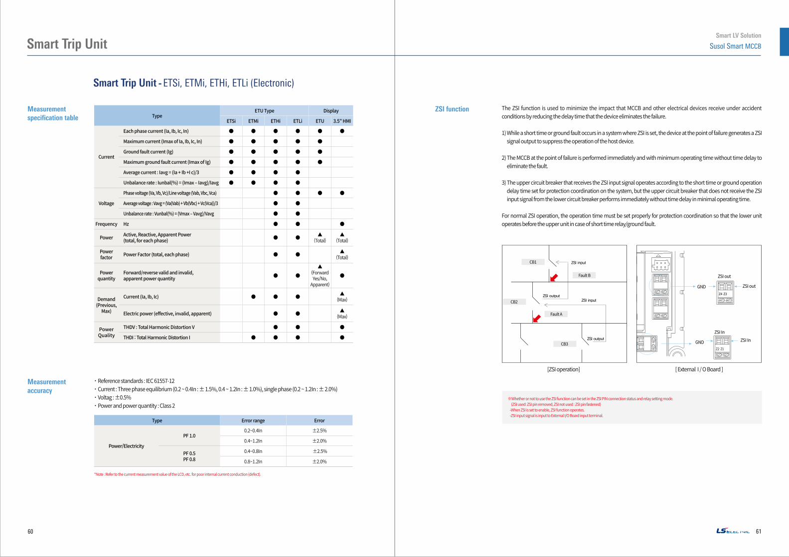
˙Reference standards : IEC 61557-12˙Current : Three phase equilibrium (0.2 ~ 0.4In : ± 1.5%, 0.4 ~ 1.2In : ± 1.0%), single phase (0.2 ~ 1.2In : ± 2.0%)˙Voltag : ±0.5%˙Power and power quantity : Class 2
Smart Trip Unit - ETSi, ETMi, ETHi, ETLi (Electronic)
Measurement specification table
Measurement accuracy
ZSI functionType
ETU Type Display
ETSi ETMi ETHi ETLi ETU 3.5” HMI
Current
Each phase current (Ia, Ib, Ic, In) ● ● ● ● ● ●
Maximum current (Imax of Ia, Ib, Ic, In) ● ● ● ● ●
Ground fault current (Ig) ● ● ● ● ●
Maximum ground fault current (Imax of Ig) ● ● ● ● ●
Average current : Iavg = (Ia + Ib +I c)/3 ● ● ● ●
Unbalance rate : Iunbal(%) = (Imax – Iavg)/Iavg ● ● ● ●
Voltage
Phase voltage (Va, Vb, Vc)/Line voltage (Vab, Vbc, Vca) ● ● ● ●
Average voltage : Vavg = (Va(Vab) + Vb(Vbc) + Vc(Vca))/3 ● ●
Unbalance rate : Vunbal(%) = (Vmax – Vavg)/Vavg ● ●
Frequency Hz ● ● ●
Power Active, Reactive, Apparent Power(total, for each phase) ● ● ▲
(Total)▲
(Total)
Power factor Power Factor (total, each phase) ● ● ▲
(Total)
Power quantity
Forward/reverse valid and invalid, apparent power quantity ● ●
▲(Forward Yes/No,
Apparent)
●
Demand (Previous,
Max)
Current (Ia, Ib, Ic) ● ● ● ▲(Max)
Electric power (effective, invalid, apparent) ● ● ▲(Max)
Power Quality
THDV : Total Harmonic Distortion V ● ● ●
THDI : Total Harmonic Distortion I ● ● ● ●
The ZSI function is used to minimize the impact that MCCB and other electrical devices receive under accident conditions by reducing the delay time that the device eliminates the failure.
1) While a short time or ground fault occurs in a system where ZSI is set, the device at the point of failure generates a ZSI signal output to suppress the operation of the host device.
2) The MCCB at the point of failure is performed immediately and with minimum operating time without time delay to eliminate the fault.
3) The upper circuit breaker that receives the ZSI input signal operates according to the short time or ground operation delay time set for protection coordination on the system, but the upper circuit breaker that does not receive the ZSI input signal from the lower circuit breaker performs immediately without time delay in minimal operating time.
For normal ZSI operation, the operation time must be set properly for protection coordination so that the lower unit operates before the upper unit in case of short time relay/ground fault.
*Note : Refer to the current measurement value of the LCD, etc. for poor internal current conduction (defect).
※Whether or not to use the ZSI function can be set in the ZSI PIN connection status and relay setting mode. (ZSI used: ZSI pin removed, ZSI not used : ZSI pin fastened)-When ZSI is set to enable, ZSI function operates.-ZSI input signal is input to External I/O Board input terminal.
Type Error range Error
Power/Electricity
PF 1.00.2~0.4In ±2.5%
0.4~1.2In ±2.0%
PF 0.5PF 0.8
0.4~0.8In ±2.5%
0.8~1.2In ±2.0%
ZSI out
GNDZ4 Z3
Z2 Z1
GND
ZSI out
ZSI InZSI In
[ZSI operation] [ External I / O Board ]
CB1 ZSI 입력
ZSI 입력ZSI 출력
ZSI 출력
CB2
Fault A
Fault B
CB3
ZSI input
ZSI output
ZSI output
ZSI input
60
Smart LV Solution
Susol Smart MCCB
61
Smart Trip Unit

Smart Trip Unit - ETSi, ETMi, ETHi, ETLi (Electronic)
Diagnosis and maintenance
Characteristic
Communication
TypeETU Type Display
ETSi ETMi ETHi ETLi ETU 3.5” HMI
Event record
System
Status change, setting change, system control, etc.Generated when an event occurs (up to 50)-Occurrence event type and occurrence time
- ● ● ● - ●
Fault
Accident (long time relay/short time relay/instantaneous/ground fault)Generated on occurrence (up to 50)-Accident type, accident value and occurrence time
- ● ● ● - ●
Maximum value record
Demand(Occurrence value and time)
Ia, Ib, Ic - ● ● ● - ●
Active/reactive/apparent power - - ● ● - ●
Power(Occurrence value and time)
Active/reactive/apparent power - - ● ●▲
(Occurrence value)
-
Device operation
Operating time (hour) - ● ● ● - ●
Circuit breaker on time (hour) - ● ● ● - ●
Circuit breaker mechanical and electrical operation frequency (number of times) - ● ● ● - ●
Circuit breaker electrical operation frequency (number of times) - ● ● ● - ●
Trip count (number of times) - ● ● ● - ●
Contact wear rate (%) - - ● ● - ●
Load profile - ● ● ● - -
Smart MCCB’s ETU can save various operation contents such as device operation and setting change. It can also check its contents through communication and HMI.
Record
1) System events ̇ Possible up to 50 records including the event type and time ̇ If the number exceeds ̇ 50, the oldest event is deleted sequentially (Roll-Over)
2) Fault event ̇ When an accident occurs due to relay operation, up to 50 records including the type and time of occurrence is possible ̇ If the number exceeds ̇ 50, the oldest event is deleted sequentially (Roll-Over) ̇ Accident waveform record: Records up to 2 accident waveforms (current and voltage waveform, 8 cycles)
3) Max. Demand and Max. Power value ̇ Records occurrence value and occurrence time
4) Device operation ̇ Operation/circuit breaker on (input) hour ̇ Circuit breaker/trip operation count ̇ Contact wear rate (%) : Wear rate according to the number of electrical openings and closings of the main body ̇ Load Profile : Hours of use according to the load used (hour) Classified into 4 levels (0~49% In, 50~79% In, 80~89% In,> 90% In)
Device management
ETU with communication function can obtain device information using communication.˙Communication related items (Communication address, speed etc.)˙Manufacturer˙Serial number˙Firmware version˙Model name, etc.
RS485 communication 1) Communication method : Modbus RTU2) Communication speed : 9,600, 19,200, 38,400 bps3) Communication distance : up to 5m (between devices), maximum number of connections is 164) DC 24V power supplied from outside5) Slave address : 1 ~ 2476) Transmission information : device status and measured values, setting information, record data, etc.※Communication is possible only when there is an external power supply (DC 24).
Tester Port communication1) External power supply (DC 12V) input2) Connected devices : i-Tester, IPBM : Relay test current signal input
BLE Communications1) Distance possible for communication : 4m (Open space standard)2) Transmission information : Device status and measured values, setting information, record data, etc.※Communication is possible only when there is an external power supply (DC 24).*When power is supplied to the device again, the device time is reset to 1 : 01 : 01 on January 1, 2018.
62
Smart LV Solution
Susol Smart MCCB
63
Smart Trip Unit