Molded Case Circuit Breakers Overview
16
Circuit Protection www.automationdirect.com/circuit-protection e31-5 Company Information Systems Overview Programmable Controllers Field I/O Software C-more & other HMI Drives Soft Starters Motors & Gearbox Steppers/ Servos Motor Controls Proximity Sensors Photo Sensors Limit Switches Encoders Current Sensors Pressure Sensors Temperature Sensors Pushbuttons/ Lights Process Relays/ Timers Comm. Terminal Blocks & Wiring Power Circuit Protection Enclosures Tools Pneumatics Appendix Product Index Part # Index Volume 13 Molded Case Circuit Breakers Overview Overview Fuji Molded Case Circuit Breakers are more compact (especially 100A, 125A, 250A frames) than any breakers on the market, so they take up less space in control panels. This product group maintains conformity to all Worldwide standards. Agency Approvals • UL listed, MCCB, File: E90584 • UL listed, Accessories, File E93289 • CE marked • CCC marked • TUV certified Standards • UL 489 • CSA C22.2 No.5 • IEC 60947-2 • EN 60947-2 • GB 14048.2 • JIS C8201-2-1, 2 (ANN.1, 2) Features • Thermal-magnetic 15A through 800A • Suitable for branch circuit protection • Rated current of 15 to 800A, max 600V • Standard type and high-interrupting capacities available in identically sized breakers • Shunt Trip, Undervoltage Release and other accessories available • Line & load lug terminals included on all MCCBs • Auxiliary switch, Alarm switch and Shunt Trip can be installed in the field • Door-mounted or flange-mounted, flex shaft operating handles • All frame sizes suitable for reverse-feed use • All breakers include mounting hardware • Terminal covers included for BW125 and BW250 frames. Terminal covers available for BW400, BW630 and BW800 frames. BW125JAGU - 3P 015 SB Fuji MCCB Frame Size 3 Pole Amp Rating Terminal Structure Fuji Molded Case Circuit Breakers Part Numbering System *Note: N.I.T.U denotes non-interchangeable trip unit. **Note: For DC or 1-phase AC applications, use the two outside poles of the 3-pole circuit breaker Fuji Electric Molded Case Circuit Breakers Technical Specifications Circuit Breaker Type Ampere Rating at 40°C No. Poles Volts Type of Trip* UL 489 Interrupting Ratings (rms Symmetrical Amperes) (kA) AC DC Volts AC (50/60 Hz) Volts DC 240 480 600 250** BW125JAGU 15-125 3 600 250 N.I.T.U 50 30 10 10 BW250JAGU 125-250 3 600 250 N.I.T.U 50 30 10 10 BW400SAGU 250-400 3 480 250 N.I.T.U 50 35 – 10 BW630RAGU 500-600 3 480 250 N.I.T.U 100 50 – 10 BW800RAGU 700-800 3 480 250 N.I.T.U 100 50 – 10
Transcript of Molded Case Circuit Breakers Overview
Circuit Protectionw w w . a u t o m a t i o n d i r e c t . c o m / c i r c u i t - p r o t e c t i o n e31-5
CompanyInformation
SystemsOverview
ProgrammableControllers
Field I/O
Software
C-more & other HMI
Drives
SoftStarters
Motors &Gearbox
Steppers/Servos
Motor Controls
ProximitySensors
Photo Sensors
Limit Switches
Encoders
CurrentSensors
PressureSensors
TemperatureSensors
Pushbuttons/Lights
Process
Relays/Timers
Comm.
TerminalBlocks & Wiring
Power
CircuitProtection
Enclosures
Tools
Pneumatics
Appendix
ProductIndex
Part #Index
Volume 13
Molded Case Circuit Breakers Overview
OverviewFuji Molded Case Circuit Breakers aremore compact (especially 100A, 125A,250A frames) than any breakers on themarket, so they take up less space incontrol panels.
This product group maintains conformityto all Worldwide standards.
Agency Approvals• UL listed, MCCB, File: E90584 • UL listed, Accessories, File E93289 • CE marked• CCC marked• TUV certified
Standards• UL 489• CSA C22.2 No.5• IEC 60947-2 • EN 60947-2• GB 14048.2• JIS C8201-2-1, 2 (ANN.1, 2)
Features • Thermal-magnetic 15A through 800A• Suitable for branch circuit protection • Rated current of 15 to 800A, max 600V• Standard type and high-interrupting
capacities available in identically sizedbreakers
• Shunt Trip, Undervoltage Release andother accessories available
• Line & load lug terminals included on allMCCBs
• Auxiliary switch, Alarm switch and ShuntTrip can be installed in the field
• Door-mounted or flange-mounted, flexshaft operating handles
• All frame sizes suitable for reverse-feeduse
• All breakers include mounting hardware • Terminal covers included for BW125 and
BW250 frames. Terminal covers availablefor BW400, BW630 and BW800 frames.
BW125JAGU - 3P 015 SBFuji MCCB Frame Size
3 PoleAmp Rating
Terminal Structure
Fuji Molded Case Circuit Breakers Part Numbering System
*Note: N.I.T.U denotes non-interchangeable trip unit.
**Note: For DC or 1-phase AC applications, use the two outside poles of the 3-pole circuit breaker
Fuji Electric Molded Case Circuit Breakers Technical Specifications
CircuitBreaker Type
Ampere Ratingat 40°C
No.Poles
Volts Typeof
Trip*
UL 489 Interrupting Ratings (rmsSymmetrical Amperes) (kA)
AC DC Volts AC (50/60 Hz) Volts DC240 480 600 250**
BW125JAGU 15-125 3 600 250 N.I.T.U 50 30 10 10
BW250JAGU 125-250 3 600 250 N.I.T.U 50 30 10 10
BW400SAGU 250-400 3 480 250 N.I.T.U 50 35 – 10
BW630RAGU 500-600 3 480 250 N.I.T.U 100 50 – 10
BW800RAGU 700-800 3 480 250 N.I.T.U 100 50 – 10

Circuit Protection 1 - 8 0 0 - 6 3 3 - 0 4 0 5e31-6Volume 13
Fuji Molded Case Circuit Breakers – 125A Frame
BW125-Frame Accessory Selection GuidePart Number Price DescriptionBW9W1SG0 <---> Field installable auxiliary contact for BW125-frame MCCBs. SPDT. Lead wires: 20AWG, 19.69” long. Left and right side mount
BW9FRG0 <---> Field installable 24 VDC/VAC shunt trip for BW125-frame MCCBs. Lead wires: 20AWG, 19.69” long. Left and right side mount
BW9FAG0 <---> Field installable 100-120 VAC, 100-110 VDC shunt trip for BW125-frame MCCBs. Lead wires: 20AWG, 19.69” long. Left and right side mount
BW9RGAR <---> Field installable 24 VDC undervoltage release for BW125-frame MCCBs. Lead wires: 20AWG, 19.69” long. Left side mount only
BW9RGAT <---> Field installable 110-130 VAC undervoltage release for BW125-frame MCCBs. Lead wires: 20AWG, 19.69” long. Left side mount only
BW9SL0CA-3 <---> Replacement lugs for BW125-frame MCCBs,. package of 3
BW9V0CA <---> NEMA 12 rotary handle for BW125-Frame. Position indicating; lock-off feature. Shaft length: 0.39”
BW9VSG0 <---> NEMA 12 rotary handle shaft for BW9V0CA for BW125-Frame. Shaft length: 6.06”
BW9F0CA-15A <---> NEMA 12 flexible shaft handle for BW125-Frame. Flange mounted. Lockable. Flex cable shaft length: 4.92’ (1.5m)
BW9F0CA-20A <---> NEMA 12 flexible shaft handle for BW125-Frame. Flange mounted. Lockable. Flex cable shaft length: 6.56 (2m)
BW9Q1CA <---> Lockout attachment. Lock not included.Note: Short-type terminal covers (gray-white) are supplied as standard.
BW125-Frame Series Three-Pole Molded Case Circuit Breakers
Part Number Price Frequency
Rated Interrupting Capacity (kA)Rated
CurrentUL489 CAN/CSA
C22.2 No. 5IEC60947-2, JIS C8201-2-1 Icu/Ics
GB14048.2 Icu/Ics
AmpereRating Voltage Interrupt
Capacity Voltage InterruptCapacity Voltage Interrupt
CapacityBW125JAGU-3P015SB <--->
50/60 Hz
15
600V/Y AC480V/� AC480V/Y AC240V AC250V DC
10 kA30 kA30 kA50 kA10 kA
500V AC440V AC400V AC380V AC240V AC250V DC
15/8 kA30/15 kA30/15 kA30/15 kA50/25 kA15/8 kA
400V AC230V AC
30/15 kA50/25 kA
BW125JAGU-3P020SB <---> 20
BW125JAGU-3P030SB <---> 30
BW125JAGU-3P040SB <---> 40
BW125JAGU-3P050SB <---> 50
BW125JAGU-3P060SB <---> 60
BW125JAGU-3P070SB <---> 70
BW125JAGU-3P075SB <---> 75
BW125JAGU-3P080SB <---> 80
BW125JAGU-3P090SB <---> 90
BW125JAGU-3P100SB <---> 100
BW125JAGU-3P125SB <---> 125Note: SCCR = UL489 interrupting capacity
Fuji BW125A series MCCBs are 125 ampframe, 3-pole, non-adjustable magnetic trip,molded case circuit breakers (MCCB). TheBW125 series is suitable for reverse feed
applications. Included with each MCCB areLine and Load-side Lug terminals, terminalcovers and mounting hardware. Accessoriesare not pre-installed and are sold separately.
BW125JAGU-3P125SBshown
BW9V0CA BW9F0CA-15A BW9FAG0 BW9RGAR BW9Q1CA

Circuit Protectionw w w . a u t o m a t i o n d i r e c t . c o m / c i r c u i t - p r o t e c t i o n e31-7
CompanyInformation
SystemsOverview
ProgrammableControllers
Field I/O
Software
C-more & other HMI
Drives
SoftStarters
Motors &Gearbox
Steppers/Servos
Motor Controls
ProximitySensors
Photo Sensors
Limit Switches
Encoders
CurrentSensors
PressureSensors
TemperatureSensors
Pushbuttons/Lights
Process
Relays/Timers
Comm.
TerminalBlocks & Wiring
Power
CircuitProtection
Enclosures
Tools
Pneumatics
Appendix
ProductIndex
Part #Index
Fuji Molded Case Circuit Breakers –125A Frame Characteristic Curves
BW125 (Rated current: 15A)
● BW125 (Rated current: 20A)
1246
1246
0.010.02
0.040.060.10.20.40.6
10
20
40
1020
4060
120180
1 1.5 2 3 4 5 6 78 10 15 20 30 40506080100Multiple of rated current
Instantaneous trippingcharacteristic500A±100A
Max. value
Min. value
Max. total fault clearing time
Min
ute
Sec
ond
Ope
ratin
g tim
e
1246
1246
0.010.02
0.040.060.10.20.40.6
10
20
40
1020
4060
120180
1 1.5 2 3 4 5 6 7 8 10 15 20 30 40 506080100Multiple of rated current
Max. value
Min. value
Max. total fault clearing time
Instantaneous trippingcharacteristic500A±100A
Min
ute
Sec
ond
Ope
ratin
g tim
e
Ambient temp. (˚C)
Rat
ed c
urre
nt
corr
ectio
n ra
tio (%
)
Reference temp. 40˚C
050403020 010150
100
150
Ambient temp. (˚C)
Rat
ed c
urre
nt
corr
ectio
n ra
tio (%
)
Reference temp. 40˚C
050403020 010150
100
150
BW125 Rated Current 20A
BW125 Rated Current 15A
Wire Range Wiring Specifications chart is onpage 31-30
Volume 13

Circuit Protection 1 - 8 0 0 - 6 3 3 - 0 4 0 5e31-8
Fuji Molded Case Circuit Breakers –125A Frame Characteristic CurvesBW125 (Rated current: 30A)
BW125 (Rated current: 40A)
Ambient temp. (˚C)
Rat
ed c
urre
nt
corr
ectio
n ra
tio (%
)
Reference temp. 40˚C
050403020 010150
100
150
050403020 010150
100
150
Ambient temp. (˚C)
Rat
ed c
urre
nt
corr
ectio
n ra
tio (%
)
Reference temp. 40˚C1246
1246
0.010.02
0.040.06
0.10.20.40.6
10
20
40
1020
4060
120180
1 1.5 2 3 4 5 6 78 10 15 20 30 40506080100Multiple of rated current
Max. value
Max. total fault clearing time
Instantaneous trippingcharacteristic500A±100A
Min
ute
Sec
ond
Ope
ratin
g tim
e
1246
1246
0.010.02
0.040.06
0.10.20.40.6
10
20
40
1020
4060
120180
1 1.5 2 3 4 5 6 7 8 10 15 20 30 40506080100Multiple of rated current
Max. value
Min. value
Max. total fault clearing time
Instantaneous trippingcharacteristic500A±100A
Min
ute
Sec
ond
Ope
ratin
g tim
e
Min. value
BW125 Rated Current 30A
BW125 Rated Current 40A
Volume 13

Circuit Protectionw w w . a u t o m a t i o n d i r e c t . c o m / c i r c u i t - p r o t e c t i o n e31-9
CompanyInformation
SystemsOverview
ProgrammableControllers
Field I/O
Software
C-more & other HMI
Drives
SoftStarters
Motors &Gearbox
Steppers/Servos
Motor Controls
ProximitySensors
Photo Sensors
Limit Switches
Encoders
CurrentSensors
PressureSensors
TemperatureSensors
Pushbuttons/Lights
Process
Relays/Timers
Comm.
TerminalBlocks & Wiring
Power
CircuitProtection
Enclosures
Tools
Pneumatics
Appendix
ProductIndex
Part #Index
Volume 13
Fuji Molded Case Circuit Breakers –125A FrameCharacteristic Curves
Rat
ed c
urre
nt
corr
ectio
n ra
tio (%
)
10 0 01 20 30 40 5050
100
150Reference temp. 40°C
Ambient temp. (°C)
1246
1246
0.010.02
0.040.060.10.20.40.6
10
20
40
1020
4060
120180
1 1.5 2 3 4 5 6 78 10 15 20 30 4050 60 80 100Multiple of rated current
Max. value
Min. valueMax. total fault clearing time
Instantaneous trippingcharacteristic10 In±20%
Min
ute
Sec
ond
Ope
ratin
g tim
e
Note: Instantaneous tripping = 10 x (rated current) ± 20% In = rated current
BW125 Current Range 50 -125A

Circuit Protection 1 - 8 0 0 - 6 3 3 - 0 4 0 5e31-18
15 to 125ABW125A Frame
125 to 250ABW250A Frame
Fuji Molded Case Circuit Breakers –Dimensions
Note: All dimensions shown in mm [inches]
Volume 13

Circuit Protection 1 - 8 0 0 - 6 3 3 - 0 4 0 5e31-22
Fuji Molded Case Circuit Breakers –Products And Accessory Compatibility
Match the Accessories with Fuji Molded Case Circuit BreakersPart Number Description BW125JAGU BW250JAGU BW400SAGU BW630RAGU BW800RAGUBW9W1SG0 Auxiliary Switch (Mounting Left and right side) X XBW9W1SHA Auxiliary Switch (Mounting Left side ONLY) X X X
BW9FRG0 Shunt Trip 24 VAC/VDC (Mounting both Left and Right sides) X XBW9FHA-R Shunt Trip 24-48 VAC/VDC (Mounting Left side ONLY) X X X
BW9FAG0 Shunt Trip 100-120 VAC, 100-110 VDC (Mounting both Left and Right sides) X X
BW9FHA-A Shunt Trip 100-280 VAC, 100-220 VDC (Mounting Left side ONLY) X X X
BW9RGAR UnderVoltage Release 24VDC (Left side ONLY) X XBW9RHA-R UnderVoltage Release 24 VAC/VDC (Left side ONLY) X X XBW9RGAT UnderVoltage Release 110-130 VAC (Left side ONLY) X XBW9RHA-1 UnderVoltage Release 120-130 VAC, 125VDC (Left side ONLY) X X X
BW9SL0CA-3 Replacement Lugs Kit for 125 Amp frame XBW9SL0GA-3 Replacement Lugs Kit for 250 Amp frame up to 175A XBW9SL1GA-3 Replacement Lugs Kit for 250 Amp frame 200A to 250A X
BW9V0CA Rotary Handle, H = 4.134"(shaft is shorter) XBW9V0GA Rotary Handle, H = 4.134"(shaft is shorter) XBW9VSG0 Optional Shaft for BW9V0CA and BW9V0GA, H = 9.843" (shorter shaft) X XBW9V0HA Rotary Handle, H = 7.48"(shaft is shorter) XBW9V0JA Rotary Handle, H = 7.48"(shaft is shorter) X XBZ-VS2 Optional Shaft for BW9V0HA and BW9V0JA, H = 9.843" (shorter shaft) X X X
BW9F0CA-15A Flange Handle (flex shaft), NEMA 12, 59“ (1.5m) cable, 125 Amp frame XBW9F0CA-20A Flange Handle (flex shaft), NEMA 12, 78.7” (2.0m) cable, 125 Amp frame XBW9F0GA-15A Flange Handle (flex shaft), NEMA 12, 59“ (1.5m) cable, 250 Amp frame XBW9F0GA-20A Flange Handle (flex shaft), NEMA 12, 78.7” (2.0m) cable, 250 Amp frame XBW9F0HA-15A Flange Handle (flex shaft), NEMA 12, 59“ (1.5m) cable, 400 Amp frame XBW9F0HA-20A Flange Handle (flex shaft), NEMA 12, 78.7” (2.0m) cable, 400 Amp frame X
BW9BTHA-L3W Terminal Cover for the 400A frame XBW9BTJA-L3W Terminal Cover for the 630A AND 800A frame X X
BW9Q1CA Lockout Attachment 125A and 250A frames X XBW9QNHA Lockout Attachment 400A, 630A and 800A frames X X X
Internal Accessory Combinations for BW Series
Available configurations
Auxiliary switchSPDTShunt trip
Undervoltage trip
Auxiliary Switch + Shunt Trip
Undervoltage + Auxiliary Switch
MCCB
Pole 3 3
BW400BW630BW800
BW125BW250
Handle
3-pole
Left Right Shunt trip Undervoltage trip Auxiliary switch
Volume 13

Circuit Protection 1 - 8 0 0 - 6 3 3 - 0 4 0 5e31-30Volume 13
Maximum Wire Sizes and Tightening Torque
Type RatedCurrent (A)
Wire Size AWG or MCM (mm2)
TighteningTorqueLugTerminal*
BW125
15 14 AWG (2.1mm2)
51 lb.-in.(5.8 N-m)
20 12 AWG (3.3mm2)30 10 AWG (5.3mm2)40 8 AWG (8.4mm2)50 8 AWG (8.4mm2)60 6 AWG (13.3mm2)70 4 AWG (21.1mm2)75 4 AWG (21.1mm2)80 4 AWG (21.1mm2)90 3 AWG (26.7mm2)100 3 AWG (26.7mm2)125 1 AWG (42.4mm2)
BW250
125 1 AWG (42.4mm2)
204 lb.-in.(23 N-m)
150 1/0 AWG (53.5mm2)175 2/0 AWG (67.4mm2)200 3/0 AWG (85.0mm2)225 4/0 AWG (107.2mm2)250 250 MCM (127mm2)
BW400
250 250 MCM (127mm2)385 lb.-in(43.5 N-m)
300 350 MCM (177mm2)350 500 MCM (253mm2)
400 3/0 AWGx2 (85.0mm2x2)282 lb-in (31.9 N-m)
BW630500 250-500 MCMx2 275 lb.-in.
(31.07 N-m)600 250-500 MCMx2
BW800700 250-500 MCMx2 275 lb.-in.
(31.07 N-m)800 3/0 AWG-300 MCMx3
Fuji Molded Case Circuit Breakers – Wire Range Specifications
Wiring • When connecting the wires, follow NEC (National Electric Code,
USA) or CEC (Canadian Electrical code Part 1, Canada) instruc-tions.
• Use copper wire rated for 75°C for connecting. UL or CSAapproved wire is recommended.
• Tighten the wire connections adequately, as a very large elec-tromagnetic force will be generated when short circuit current isgenerated.
• Perform additional tightening of the terminal screws periodically.
Caution• Adhere to the number of strands of wire indicated in the
table.• Multiconductor wire can not be connected. • Two wires cannot be connected to the lug terminal at once.• Do not solder the end of the wire.
Allowable Wire Specifications for Lug TerminalsWire Size AWG or MCM (mm2) Number of Wire Strands
14 to 2 (2.1 to 33.6) 71 to 4/0 (42.4 to 107.2) 19250 to 500 (127 to 250) 37
*Note: Lug terminals are supplied as standard.
Circuit Protectionw w w . a u t o m a t i o n d i r e c t . c o m / c i r c u i t - p r o t e c t i o n e31-23
CompanyInformation
SystemsOverview
ProgrammableControllers
Field I/O
Software
C-more & other HMI
Drives
SoftStarters
Motors &Gearbox
Steppers/Servos
Motor Controls
ProximitySensors
Photo Sensors
Limit Switches
Encoders
CurrentSensors
PressureSensors
TemperatureSensors
Pushbuttons/Lights
Process
Relays/Timers
Comm.
TerminalBlocks & Wiring
Power
CircuitProtection
Enclosures
Tools
Pneumatics
Appendix
ProductIndex
Part #Index
Volume 13
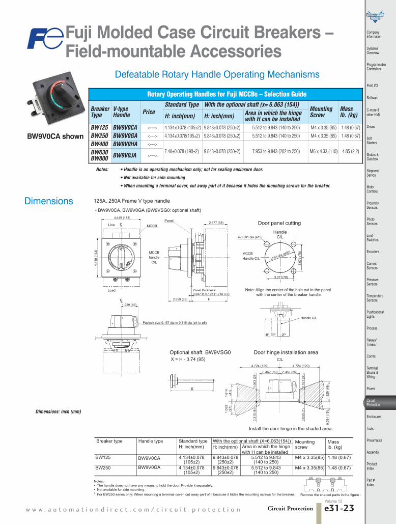
Fuji Molded Case Circuit Breakers – Field-mountable Accessories
Rotary Operating Handles for Fuji MCCBs – Selection Guide
BreakerType
V-typeHandle Price
Standard Type With the optional shaft (x= 6.063 (154)) MountingScrew
Mass lb. (kg)H: inch(mm) H: inch(mm) Area in which the hinge
with H can be installedBW125 BW9V0CA <---> 4.134±0.078 (105±2) 9.843±0.078 (250±2) 5.512 to 9.843 (140 to 250) M4 x 3.35 (85) 1.48 (0.67)
BW250 BW9V0GA <---> 4.134±0.078(105±2) 9.843±0.078 (250±2) 5.512 to 9.843 (140 to 250) M4 x 3.35 (85) 1.48 (0.67)
BW400 BW9V0HA <--->7.48±0.078 (190±2) 9.843±0.078 (250±2) 7.953 to 9.843 (202 to 250) M6 x 4.33 (110) 4.85 (2.2)BW630
BW800 BW9V0JA <--->
Notes: • Handle is an operating mechanism only; not for sealing enclosure door.
• Not available for side mounting
• When mounting a terminal cover, cut away part of it because it hides the mounting screws for the breaker.
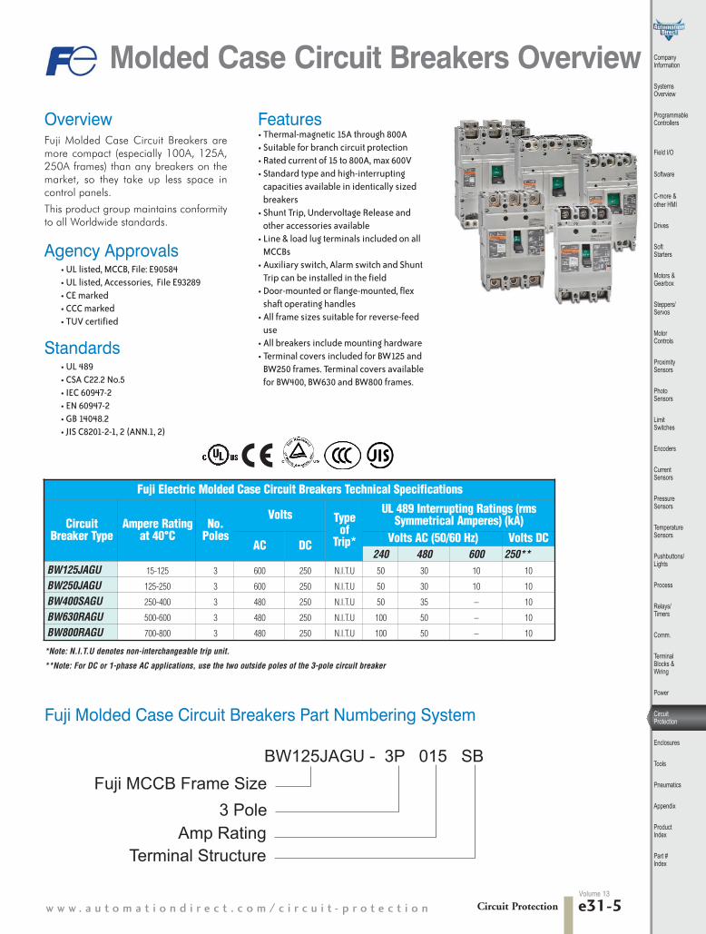
Defeatable Rotary Handle Operating Mechanisms
125A, 250A Frame V type handle
• BW9V0CA, BW9V0GA (BW9VSG0: optional shaft)
Area in which the hingewith H can be installed
H: inch(mm)Standard typeH: inch(mm)
Breaker type Handle type With the optional shaft (X=6.063(154)) Mountingscrew
M4 x 3.35(85)
M4 x 3.35(85)
Mass lb. (kg)
1.48 (0.67)
1.48 (0.67)
BW125
BW250
BW9V0CA
BW9V0GA
4.134±0.078(105±2)
4.134±0.078(105±2)
5.512 to 9.843(140 to 250)
5.512 to 9.843(140 to 250)
9.843±0.078(250±2)
9.843±0.078(250±2)
Door panel cuttingHandle
C/L4-0.591 dia (ø15)
MCCBHandle C/L
3.071(78)
3.07
1 (7
8)1.929 (49)
Padlock size 0.157 dia to 0.315 dia (ø4 to ø8)
LC
4.44
9 (1
13)
4.449 (113)2.677 (68)
LC
2.559 (65) H
MCCBhandle
C/L
MCCBLine
Load
Panel
Note: Align the center of the hole cut in the panel with the center of the breaker handle.
Handle C/L
P4 P3 P2
Door hinge installation areaOptional shaft BW9VSG0X = H - 3.74 (95)
Install the door hinge in the shaded area.
2.362 (60) 2.362 (60)
4.724 (120) 4.724 (120)
C/L
1.06
3 (2
7)1.
614
(41)
1.06
3 (2
7)0.
315
(8)
1.18
1 (3
0)0.
039
(1)
1.92
9 (4
9)0.
591
(15)
X
Notes: • The handle does not have any means to hold the door. Provide it separately.• Not available for side mounting.* For BW250 series only: When mounting a terminal cover, cut away part of it because it hides the mounting screws for the breaker. Remove the shaded parts in the figure .
Panel thickness:0.047 to 0.126 (1.2 to 3.2)
3.543 dia (ø90)
BW9V0CA shown
Dimensions: inch (mm)
Dimensions

Circuit Protection 1 - 8 0 0 - 6 3 3 - 0 4 0 5e31-24Volume 13
Fuji Molded Case Circuit Breakers – Field-mountable Accessories
400A, 630A, 800A Frame V type handle
• BW9V0HA, BW9V0JA (BZ-VS2: optional shaft)
Breaker type Handletype
Standard typeH: inch(mm)
With the optional shaft (X = 3.48 (88.5) Mass lb. (kg)H: inch(mm) Area in which the hinge
with H can be installed
BW400
BW630, BW800
BW9V0HA
BW9V0JA
7.48±0.078(190±2)
9.843±0.078(250±2)
7.953 to 9.843 (202 to 250) 4.85 (2.2)
Note: • The handle is an operating mechanism only; not for sealing enclosure door. • Not available for side mounting
X
Optional shaft (BZ-VS2)
2.16
5 (5
5)
3.937 (100)
H 2.48 (63)
0.39
4 (1
0)
7.874 (200)
OFF
1.18
1 (3
0)
Panel Decorativeplate
Mountingscrew
Load
Install the door hinge in the shaded area.
Line5.906 (150)
5.90
6 (1
50)
5.90
6 (1
50)
Lock platePadlock size 0.157 dia (ø4) to
0.315 dia (ø8)(Up to two 0.315 dia (ø8) padlocks can be mounted.)
MCCB handle C/L
4.40
9 (1
12)
4.409 (112)
4-0.394 dia (ø10)
MCCBhandle C/L
MCCBhandle C/L
Door panel cutting
Note: Align the center of the hole cut in the panel with the center of the breaker handle.
When using the BZ-VS2 extension shaft to adjust dimension H, cut it according to the equation below.X=H−6.358 (161.5)
Panel thickness: 0.063-0.126 (1.6-3.2)
5.433 dia (ø138)
M6 x 4.33 (110)
Dimensions: inch (mm)
Dimensions

Circuit Protectionw w w . a u t o m a t i o n d i r e c t . c o m / c i r c u i t - p r o t e c t i o n e31-25
CompanyInformation
SystemsOverview
ProgrammableControllers
Field I/O
Software
C-more & other HMI
Drives
SoftStarters
Motors &Gearbox
Steppers/Servos
Motor Controls
ProximitySensors
Photo Sensors
Limit Switches
Encoders
CurrentSensors
PressureSensors
TemperatureSensors
Pushbuttons/Lights
Process
Relays/Timers
Comm.
TerminalBlocks & Wiring
Power
CircuitProtection
Enclosures
Tools
Pneumatics
Appendix
ProductIndex
Part #Index
Flex Handle Specifications
Operating instructions
• Operating handle facing up, Breaker is in ON position.• Operating handle facing down, Breaker is in OFF position or is reset.• Panel door cannot be opened when in ON, OFF or Trip position. In order to
open the door, the handle must be turned toward reset position.• Release screw is standard. If you want to open a panel door in ON position,
please turn the release screw using flat head screwdriver.
Frame Size 125A frame 250A frame 400A frameMechanical Endurance(cycles) 10,000 8,000 6,000
Ambient Temperature 14 to 140F (- 10 to 40°C)
Relative Humidity less than 95% RH
Protection NEMA Type12 IP54 (IEC60529)
Conforming Standards NFPA 79(2007), ANSI(Lockout), OSHA(1910.147, Lockout/tagout), UL489(cUL)
Environment No excessive dust, smoke, corrosive gases, flammable gases, steam or salt.
Flex Shaft Handles for Fuji MCCBs – Selection GuideBreakerType Handle Type Price Description
BW125BW9F0CA-15A <---> Nema 12 flexible shaft handle for 125A frame. 59.06” (1.5m)cable
BW9F0CA-20A <---> Nema 12 flexible shaft handle for 125A frame. 78.74” (2m) cable
BW250BW9F0GA-15A <---> Nema 12 flexible shaft handle for 250A frame. 59.06” (1.5m)cable
BW9F0GA-20A <---> Nema 12 flexible shaft handle for 250A frame. 78.74” (2m) cable
BW400BW9F0HA-15A <---> Nema 12 flexible shaft handle for 400A frame. 59.06” (1.5m)cable
BW9F0HA-20A <---> Nema 12 flexible shaft handle for 400A frame. 78.74” (2m) cable
Defeatable Flexible Handle Operating Mechanisms
Fuji Molded Case Circuit Breakers – Field-mountable Accessories
BW9F0CA-15A shown
Terminal cover Mounting screw
M4 x 90
Drive section Operation section
Insulation barrier
Terminal cover
To operation section
Panel drilling
0.197dia(M4 or ø5)
Handle
Panel
Panel
Cable
Release lever
Lock lever
Release screw
OFF lock
Concave for ON lock*2
1.102(28) or more RESET
6.10
2 (1
55)
5.19
7 (1
32)
0.86
6(2
2)
1.08
3(2
7.5)
0.49
2(1
2.5)
1.08
3 (2
7.5)
5.19
7 (1
32) 10
.827
(275
)
Max
. 2.7
17( 6
9)
5.866 (149)
5.70
9 (1
45)
150˚
2.95
3 (7
5)
4.68
5 (1
19)
1.14
2 (2
9)
2.55
9 (6
5)
3.937 (100)MCCB/ELCB
ELCB
MCCB/ELCB
MCCB/ELCB
4.094 (104)2.756 (70)
3.543 (90)
1.181 (30)
4.606 (117)
2.362 (60)
1.772 (45)
3.15 (80) ON 1.063(27)
1.142 (29)
2.244(57)
2.244 (57)
0.512(13)
2-0.27
6 dia
(ø7)
R0.256 (R6.5)
2-0.217 dia (ø5.5)
*1
• BW9F0CA
• This product consists of a drive section and an operation section.• The operation section can be mounted either to the right or to the left on the panel depending on the mounting position of the release lever.• For the OFF lock, up to three 0.394 dia (φ10) padlocks can be used at one time
*1 Set the height to 20mm or 30mm (0.787” or 1.181”). Adjust the lock lever depending on the setting.*2 In the ON position, up to two padlocks or lockout hasps up to 0.394 dia (10mm) can be
used at one time.
Volume 13

Circuit Protection 1 - 8 0 0 - 6 3 3 - 0 4 0 5e31-26
Fuji Molded Case Circuit Breakers – Field-mountable Accessories
35
g
Operation sectionDrive section
To operation section
Panel drilling
Handle
Panel
Mounting screwM4 x 90
Panel
Cable
Release lever
Lock lever
Release screw
OFF lock
Concave for ON lock*2
1.102 (28) or more
RESET
0.86
6 (2
2)
4.96
1 (1
26)
1.08
3 (
27.5
)
0.49
2 (
12.5
)
1.08
3 (2
7.5)
5.19
7 (1
32)
10.8
27 (
275)
6.49
6 (
165)
3.46
5(8
8)
Max
. 2.7
17 (
69)
5.866 (149)
5.70
9 (1
45)
150˚
2.95
3 (
75)
4.68
5 (1
19)
1.14
2 (2
9)
2.362 (60)
1.772 (45)
3.15 (80) ON 1.063 (27)
1.142 (29)2.244 (57)
4.094 (104)4.528 (115)
2.756 (70)
4.606 (117)3.543(90)
Insulationbarrier
Terminalcover 2.244 (57)
1.378 (35)
0.197 dia(M4 or ø5)
0.512 (13)
2-0.2
76 di
a (ø7)
R0.256 (R6.5)
2-0.217 dia (ø5.5)
*1
MCCB/ELCB
MCCB/ELCB
MCCB/ELCB
MCCB/ELCB
• BW9F0GA
• This product consists of a drive section and an operation section.• The operation section can be mounted either to the right or to the left on the panel depending on the mounting position of the release lever.• For the OFF lock, up to three 0.394 dia (φ10) padlocks can be used at one time
*1 Set the height to 20mm or 30mm (0.787” or 1.181”). Adjust the lock lever depending on the setting.*2 In the ON position, up to two padlocks or lockout hasps up to 0.394 dia (10mm) can be
used at one time.
Dimensions: inch (mm)• BW9F0HA
Mounting screwM6 x 110
Operation sectionDrive section
To operation section
Panel drilling
Handle
Panel
Panel
Cable
Release lever
Lock lever
Release screw
OFF lock
Concave for ON lock*2
1.102 (28) or moreRESET
0.86
6 (2
2)
8.42
5 (2
14)
to 8
.504
(21
6)
1.08
3(2
7.5)
0.49
2 (1
2.5)
1.08
3 (2
7.5)
5.19
7 (1
32) 10
.827
(27
5)
10.8
27 (
275)
Max
. 2.7
17
(69)
5.866 (149)
5.70
9 (1
45)
150˚
4.68
5 (1
19)
1.14
2 (2
9)
2.362 (60)
1.772 (45)
3.15 (80) ON1.063 (27)
1.142 (29)2.244 (57)
6.102(155)Terminalcover
Insulationbarrier
6.732 (171)
2.244 (57)
1.732 (44)0.276 dia (M6 or ø7)
0.512 (13)
2-0.
276
(ø7)
R0.256 (R6.5)
2-0.217 dia (ø5.5)
*1
• This product consists of a drive section and an operation section.• The operation section can be mounted either to the right or to the left on the panel depending on the mounting position of the release lever.• For the OFF lock, up to three 0.394 dia (φ10) padlocks can be used at one time
*1 Set the height to 20mm or 30mm (0.787” or 1.181”). Adjust the lock lever depending on the set*2 In the ON position, up to two padlocks or lockout hasps up to 0.394 dia (10mm) can be
used at one time.
MCCB/ELCB
MCCB/ELCB
MCCB/ELCB
MCCB/ELCB
7.48 (190)
5.512 (140)
4.252 (108)
2.95
3 (7
5)
Volume 13

Circuit Protectionw w w . a u t o m a t i o n d i r e c t . c o m / c i r c u i t - p r o t e c t i o n e31-27
CompanyInformation
SystemsOverview
ProgrammableControllers
Field I/O
Software
C-more & other HMI
Drives
SoftStarters
Motors &Gearbox
Steppers/Servos
Motor Controls
ProximitySensors
Photo Sensors
Limit Switches
Encoders
CurrentSensors
PressureSensors
TemperatureSensors
Pushbuttons/Lights
Process
Relays/Timers
Comm.
TerminalBlocks & Wiring
Power
CircuitProtection
Enclosures
Tools
Pneumatics
Appendix
ProductIndex
Part #Index
Volume 13
Shunt Trips
Shunt Trips for Fuji MCCBs – Selection GuidePart Number Price Description
BW9FRG0 <--->Field installable 24 VAC/VDC shunt trip for BW125 and BW250 series MCCB.Left and right side mounting. Lead wires 20AWG, 19.69” long.
BW9FHA-R <--->Field installable 24/48 VAC/VDC shunt trip for BW400, BW630 and BW800 series MCCB.Left side mounting only. Lead wires 20AWG, 19.69” long.
BW9FAG0 <--->Field installable 100/120 VAC, 100-110 VDC shunt trip for BW125 and BW250 series MCCB.Left and right side mounting. Lead wires 20AWG, 19.69” long.
BW9FHA-A <---> Field installable 100/240 VAC, 100-220 VDC shunt trip for BW400, BW630 and BW800 seriesMCCB.Left side mounting only. Lead wires 20AWG, 19.69” long.
Fuji Molded Case Circuit Breakers – Accessories
Auxiliary Contacts for Fuji MCCBs – Selection GuideBreakerType Part Number Price Description
BW125BW250 BW9W1SG0
<--->Auxiliary switch for for 125A and 250A frame. Mounting left and right side
<--->
BW400BW630BW800
BW9W1SHA<---> Auxiliary switch for for 400A , 630A and 800A frame. Mounting left side
ONLY<--->
Ratings of Auxiliary SwitchesStandard Type
Breaker TypeRatedThermalCurrent (A)
Make/Break Current (A)MinimumLoad CurrentAC DC
Voltage (V) Res. Load Ind. Load Voltage (V) Res. Load Ind. Load
BW125,BW250, BW400BW630, BW800
5
24 5 5 24 4 35V DC 160 mA
30V DC 30 mA
48 5 5 48 2.5 1
125 5 3 125 0.4 0.4
250 3 2 250 0.2 0.2
Ratings of Shunt Trips
Breaker TypeAC DC
Time Rating of Coil Operating Time (ms)Voltage (V) VA Voltage (V) W
BW125, BW25024 50 24 50 Continuous
(with 1 N.O. contact to prevent coil burnout)
13-21100-120 50 100-110 50
BW400,BW630, BW800
24-48 2 24-48 2Continuous 8-20
100-240 3 100-220 3
Note: Allowable operating voltage AC voltage: 85% to 110% of coil rated voltageDC voltage: 75% to 125% of coil rated voltage
Auxiliary Contacts
BW9W1SHA shown
BW9FRG0 shown
The auxiliary contacts are accessory contacts for the indication of circuit breaker open-closed or tripped.
Shunt Trip is for remote tripping (opening) of crircuit breaker.
Operation of auxiliary switches Accessory
Auxiiary switch
SPDT(1)
Handle position
ON OFF Trip
11/AXcL
12/AXbL
14/AXaL11/AXcL
12/AXbL
14/AXaL

Circuit Protection 1 - 8 0 0 - 6 3 3 - 0 4 0 5e31-28Volume 13
Fuji Molded Case Circuit Breakers – Accessories
Replacement Lugs
Replacement Lug Kits for Fuji MCCBs – Selection GuidePart Number Price Description
BW9SL0CA-3 <--->Replacement lug kit for BW125 series MCCB. 75°C. Cu onlyPackage of 3
BW9SL0GA-3 <--->Replacement lug kit for BW250 series up to 175A MCCB. 75°C. Cu onlyPackage of 3
BW9SL1GA-3 <--->Replacement lug kit for BW250 MCCB series 200A to 250A. 75°C. Cu onlyPackage of 3
Ratings of Undervoltage Trip
Breaker TypeAC DCVoltage (V) VA Voltage (V) W
BW125*1BW250*1
– – 24 5
110 - 130 5 – –
BW400*2BW630*2BW800*2
24 2 24 2
120 - 130 3 125 3
Undervoltage Releases for Fuji MCCBs – Selection GuideBreaker Type Part Number Price DescriptionBW125, BW250 BW9RGAR <---> Undervoltage Release 24V DC (Left side ONLY)
BW125, BW250 BW9RGAT <---> Undervoltage Release 110 to 130 VAC VAC/VDC (Left side ONLY)
BW400, BW630, BW800 BW9RHA-R <---> Undervoltage Release 24 VAC/VDC (Left side ONLY)
BW400, BW630, BW800 BW9RHA-1 <---> Undervoltage Release 120 to 130 VAC 125 VDC (Left side ONLY)
Note: Allowable operating voltage: AC voltage: 85% to 110% of coil rated voltageDC voltage: 75% to 125% of coil rated voltage.
*1 Reset-allowed type: When the breaker handle is in the OFF or RESET state, trippingdoes not occur, even if the undervoltage trip coil is not energized.Turning ON with the undervoltage trip coil not energized causes normal tripping.
*2 Reset-prohibited type: When the undervoltage trip coil is not energized, reset oper-ation cannot reset the tripped breaker to the OFF state.
Undervoltage Releases
BW9SL0GA-3 shown
BW9RGAR shown
Undervoltage Release will trip the circuit breaker when connected voltage drops to lessthan 70% of undervoltage release voltage rating. It will allow the circuit breaker to close(ON) when voltage is approximately 85% of rated voltage.

Circuit Protectionw w w . a u t o m a t i o n d i r e c t . c o m / c i r c u i t - p r o t e c t i o n e31-29
CompanyInformation
SystemsOverview
ProgrammableControllers
Field I/O
Software
C-more & other HMI
Drives
SoftStarters
Motors &Gearbox
Steppers/Servos
Motor Controls
ProximitySensors
Photo Sensors
Limit Switches
Encoders
CurrentSensors
PressureSensors
TemperatureSensors
Pushbuttons/Lights
Process
Relays/Timers
Comm.
TerminalBlocks & Wiring
Power
CircuitProtection
Enclosures
Tools
Pneumatics
Appendix
ProductIndex
Part #Index
Volume 13
Fuji Molded Case Circuit Breakers – Accessories
Terminal CoversTerminal covers act as guards to shield theoperator from touching live terminations. Theyfit either the line or load side.
Lockout Attachment
Terminal Covers for Fuji MCCBs – Selection Guide
Breaker Series Part Number Price DescriptionDimensions inch (mm)
A B C
BW400 BW9BTHA-L3W <---> Gray-white Long type terminal cover for FujiMCCBs. For line side and load side. 2/pk 6.772 (172) 4.331 (110) 3.858 (98)
BW630, BW800 BW9BTJA-L3W <---> Gray-white Long type terminal cover for FujiMCCBs. For line side and load side. 2/pk 8.268 (210) 6.102 (155) 3.858 (98)
Note: Gray-white short type terminal covers are provided with breakers as standard for 125 and 250 Amp frames.
Lockout Attachments for Fuji MCCBs – Selection Guide
Breaker Series Part Number Price Description
BW125BW250 BW9Q1CA <--->
Use to lock out BW125 and BW 250 series MCCBs. Lock not included
BW400, BW630, BW800 BW9QNHA <--->Use to lock out BW400, BW600 and BW800 MCCBs. Lock not included.
BW9BTHA-L3Wshown
BW9Q1CA shown
Dimensions of Terminal Covers: inch (mm)
Breaker
A C
B

Circuit Protection 1 - 8 0 0 - 6 3 3 - 0 4 0 5e31-30Volume 13
Maximum Wire Sizes and Tightening Torque
Type RatedCurrent (A)
Wire Size AWG or MCM (mm2)
TighteningTorqueLugTerminal*
BW125
15 14 AWG (2.1mm2)
51 lb.-in.(5.8 N-m)
20 12 AWG (3.3mm2)30 10 AWG (5.3mm2)40 8 AWG (8.4mm2)50 8 AWG (8.4mm2)60 6 AWG (13.3mm2)70 4 AWG (21.1mm2)75 4 AWG (21.1mm2)80 4 AWG (21.1mm2)90 3 AWG (26.7mm2)100 3 AWG (26.7mm2)125 1 AWG (42.4mm2)
BW250
125 1 AWG (42.4mm2)
204 lb.-in.(23 N-m)
150 1/0 AWG (53.5mm2)175 2/0 AWG (67.4mm2)200 3/0 AWG (85.0mm2)225 4/0 AWG (107.2mm2)250 250 MCM (127mm2)
BW400
250 250 MCM (127mm2)385 lb.-in(43.5 N-m)
300 350 MCM (177mm2)350 500 MCM (253mm2)
400 3/0 AWGx2 (85.0mm2x2)282 lb-in (31.9 N-m)
BW630500 250-500 MCMx2 275 lb.-in.
(31.07 N-m)600 250-500 MCMx2
BW800700 250-500 MCMx2 275 lb.-in.
(31.07 N-m)800 3/0 AWG-300 MCMx3
Fuji Molded Case Circuit Breakers – Wire Range Specifications
Wiring • When connecting the wires, follow NEC (National Electric Code,
USA) or CEC (Canadian Electrical code Part 1, Canada) instruc-tions.
• Use copper wire rated for 75°C for connecting. UL or CSAapproved wire is recommended.
• Tighten the wire connections adequately, as a very large elec-tromagnetic force will be generated when short circuit current isgenerated.
• Perform additional tightening of the terminal screws periodically.
Caution• Adhere to the number of strands of wire indicated in the
table.• Multiconductor wire can not be connected. • Two wires cannot be connected to the lug terminal at once.• Do not solder the end of the wire.
Allowable Wire Specifications for Lug TerminalsWire Size AWG or MCM (mm2) Number of Wire Strands
14 to 2 (2.1 to 33.6) 71 to 4/0 (42.4 to 107.2) 19250 to 500 (127 to 250) 37
*Note: Lug terminals are supplied as standard.