MEK 4450 Terms & Notation Multiphase flow – … · Terms & Notation Multiphase flow –...
27
27.10.2015 MEK 4450 Terms & Notation Multiphase flow – Applications Conservation equations
Transcript of MEK 4450 Terms & Notation Multiphase flow – … · Terms & Notation Multiphase flow –...

27.10.2015
MEK 4450Terms & Notation
Multiphase flow – ApplicationsConservation equations

A
Multiphase flow terms, notation
27.10.2015
gA
oA
wA
Gas
OilWater
Void fraction:
Oil holdup:
Water holdup:
Total holdup: wo
ww
oo
g
AAAA
AA
//
/
Ug
Uo
Uw

Multiphase flow terms, notation
27.10.2015
z
y
G
Name Dimension Legend .e J/kg Specific internal energyh J/kg Specific enthalpyp Pa PressureS m Wetted lengthr kg/m3 Densitya, b, g - Gas, liquid bulk, droplet fractionst Pa Shear stressyE kg/(sm3) Droplet entrainment rateyD kg/(sm3) Droplet deposition rate
4
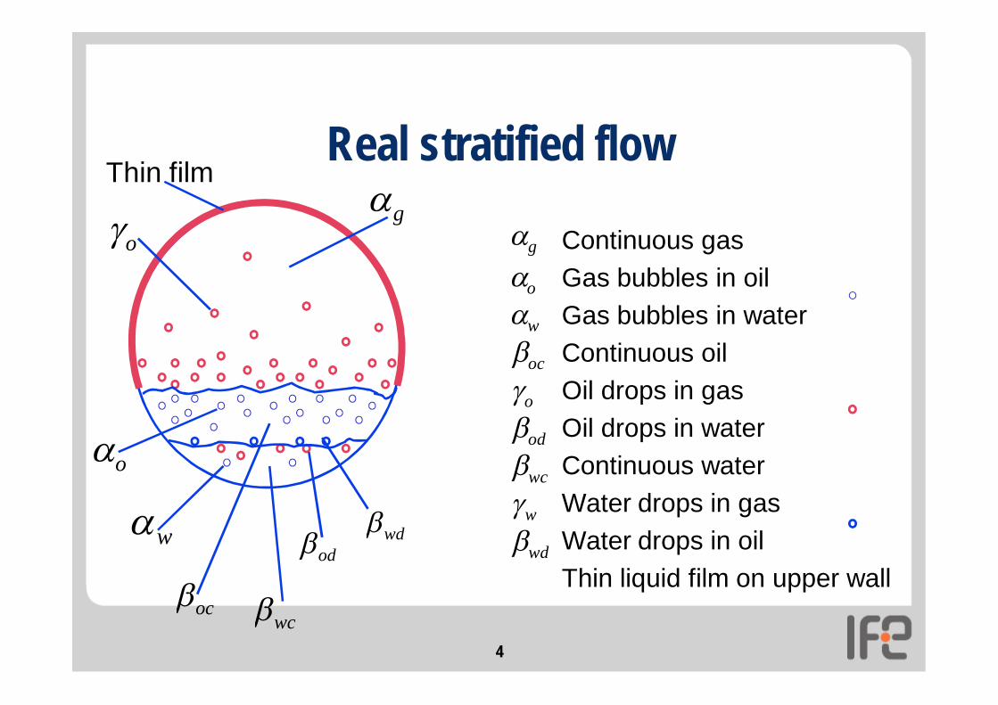
Real stratified flow
Continuous gasGas bubbles in oilGas bubbles in waterContinuous oilOil drops in gasOil drops in waterContinuous waterWater drops in gasWater drops in oilThin liquid film on upper wall
wd
w
wc
od
o
oc
w
o
g
o
w
o
ocod wd
Thin film
wc
g

Flow regimes
Depend on • phase velocities• phase quantity• pipeline orientation• flow system
• gas/liquid• liquid/liquid
27.10.2015
oil
gas
IFE Lab data

Flow regimes: Near horizontalGas/liquid regimes:• Stratified• Annular
Slug• Bubble
Liquid/liquid regimes:• Stratified (separated) • Partly separated/dispersed • Dispersed oil/water flow

Flow regimes: Near verticalGas/liquid regimes:• (a-b) bubble flow• (c-d) slug/churn flow• (e) annular flow
Liquid/liquid regimes:Dispersed
.:.:
.: .:.:
.:
.:.:
.:
.:.:
.:
.:.:
.: .:.: .:
.:.:
.:
.:.:
.:
.:.:
.:
.:.:
.:
a b c d e

Transition criteria
27.10.2015
Large WaveStratified
Slug
BubbleLiquid velocity
Gas velocity

Flow regime transitions• The most important flow regime transition in pipelines
is from stratified flow to slug flow• Two conditions must be fulfilled for slug flow to exist:
• Stratified flow must be unstable (Kelvin-Helmholtz instability)• Slugs that are formed must be able to grow (Minimum slip)
• The Kelvin-Helmholtz criterion tells that the stratified flow region gets smaller with increasing pressure
• Experimental data show that the slug flow region also gets smaller with increasing pressure
• For high pressure we get a region of large wave flow in between stratified and slug

27.10.2015
In between
slugs are stable
stratified flow is stable
USL
USG
neither is stable

Multiphase Flow Main Challenges
• Pressure loss• Liquid management
• Pipeline diameter selection• Liquid inventory control
• Normal operation• Water accumulation
• Rate changes, shut-down and Restart• Pigging
• Sizing of process equipment, e.g. separators/slug catchers
• Prediction and control of slugging

Stratified flow in horizontal gas condensate pipe
• A small stream of condensate on top of a small stream of water• The pressure gradient drives the gas which drives the condensate
which drives the water• Typical values: Gas velocity Ug = 3 m/s, liquid velocity Ul = 1 m/s
Liquid holdup h = 0.01Superficial velocities:Usg = 3 m/s Usl = hUl = 1 cm/s
• Liquid transport modified by droplets in gas and water droplets in condensate/condensate droplets in water
p1 p2
Ug
UhUw
Forces ongas
Forces oncondensate
Forces onwater
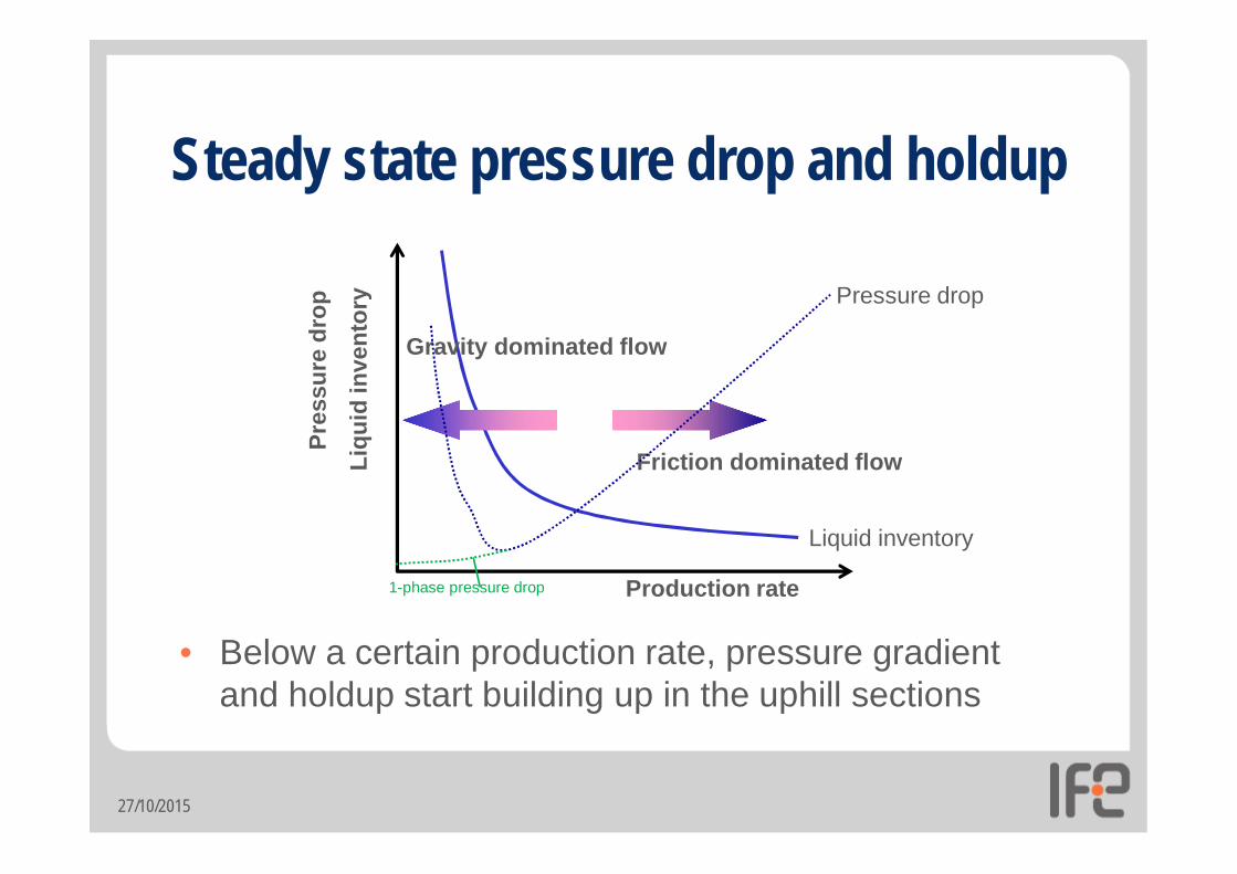
Steady state pressure drop and holdup
• Below a certain production rate, pressure gradient and holdup start building up in the uphill sections
27/10/2015
Liqu
id in
vent
ory
Production rate
Friction dominated flow
Gravity dominated flowPr
essu
re d
rop Pressure drop
Liquid inventory
1-phase pressure drop

Pipe diameter selection• Too small diameter:
• Large pressure drop due to friction at high production rates
• Too large diameter:• Too low velocity
• High holdup and flow instabilities at low production rates• Large liquid surges during production start-up or ramp-up• Possibly even severe slugging
• More expensive pipelines
• In 1-phase flow you can just make the pipe big enough• In multiphase flow you have to balance capacity needs
with need to avoid liquid accumulation and instabilities
27.10.2015

Liquid surge during ramp-up
27.10.2015
Liqu
id in
vent
ory
Production rateQ1 Q2
Liquid flowing from pipeline into slug catcher when increasing rate from Q1 to Q2

PIPELINE WATER HOLDUP PROFILE
0
5
10
15
20
0 20000 40000 60000 80000
Pipeline Distance
Wat
er H
oldu
p (%
)
0
400
800
1200
1600
Elevation (m)
Elevation
WaterHoldup
Liquid accumulation and water separation in low points
• Increased liquidaccumulationand pressure drop
• Large water slugsdisturb process
• Corrosion
• WATER
Potential problems in multiphase flow

Potential problems in multiphase flow• SHUT-IN/RESTART and RATE CHANGES
• Liquid redistributes due to gravity during shut-in• On startup, liquid in dips can exit the pipeline as large slugs
as flow is ramped up
B-Gas and Liquid Outlet Flow
A-Liquid Distribution After Shutdownshutdown
Flow
rate
gasliquid

Potential problems in multiphase flow• PIGGING
• Push a “pig” device through the pipe to• Push out excess liquid and/or wax on the pipe wall• Inspect the pipe for corrosion and wax using an instrumented pig
• Pigging the line can create a large liquid slugahead of the pig
• The pigging operation can be optimized using simulations
A: Slug build-up
B. front arrival
C. slug surface
D. Pig arrivalTime
Flow
rate
gasliquid
A B C D

Potential problems in multiphase flow
• SEVERE SLUGGING• A: Low spots fills with liquid and
flow is blocked• B: Pressure builds up behind the
blockage• C&D: When pressure becomes
high enough, gas blows liquid out of the low spot as a slug
A. Slug formation
B.Slug production
C. Gas penetration
D. Gas blow-down
– Severe slugs can cause large pressure swingsand liquid surges out of pipeline.
– Severe slugging requires a dynamic modelto predict and control
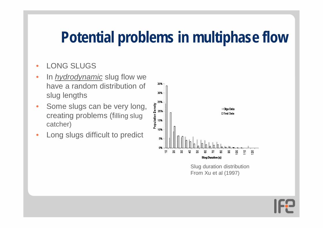
Potential problems in multiphase flow• LONG SLUGS• In hydrodynamic slug flow we
have a random distribution of slug lengths
• Some slugs can be very long, creating problems (filling slug catcher)
• Long slugs difficult to predict
Slug duration distributionFrom Xu et al (1997)

Troll gas: Onshore slug-catcher

One-dimensional multiphasepipe flow simulators
• One dimensional models for multiphase flow of gas, oil and water in wells, pipelines and networks
• Steady state and dynamic models• 1-D conservation equations for mass,
momentum and energy• Experimental experience used in
developing closure relations• Wall and interfacial friction factors• Transport of drops and bubbles
• Testing against field data important for validation
23
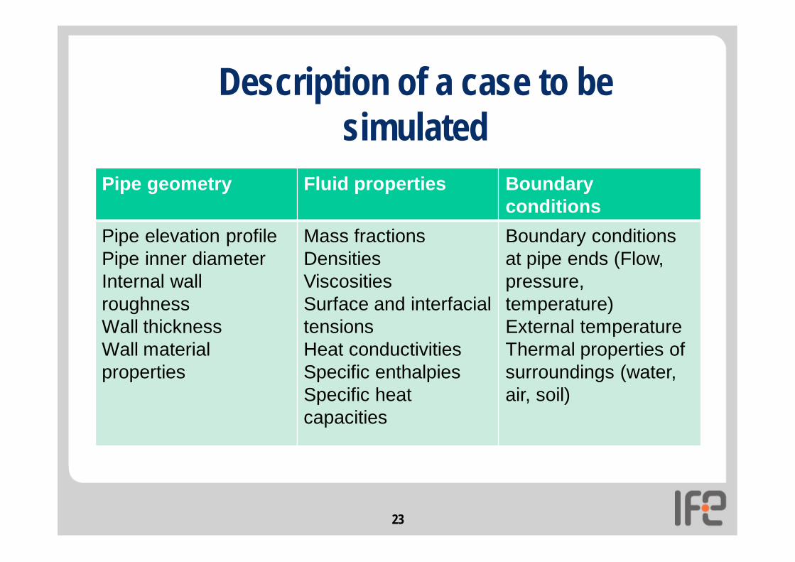
Description of a case to be simulated
Pipe geometry Fluid properties Boundaryconditions
Pipe elevation profilePipe inner diameterInternal wall roughnessWall thicknessWall material properties
Mass fractionsDensitiesViscositiesSurface and interfacial tensionsHeat conductivitiesSpecific enthalpiesSpecific heat capacities
Boundary conditions at pipe ends (Flow, pressure, temperature)External temperatureThermal properties of surroundings (water, air, soil)

CFD models for multiphase flow• Standard CFD commercial codes are widely used for
simulating laminar and turbulent single phase flow• Multiphase flow give us several new challenges
• Where is the interface?• Large scale interfaces (stratified flow), small scale interfaces
(bubbly flow) or both at the same time• Continuous phases typically described by Euler methods
(i.e. Reynolds averaged Navier-Stokes equations)• Dispersed phases typically described by either Lagrange
methods (tracking each bubble/drop/particle) or Euler methods• More difficult when a phase is both continuous and dispersed
27/10/2015

Eulerian CFD methods for multiphase flow• Diffuse interface methods
• Volume of Fluid (VOF) method• Computes volume fraction of each phase in each control volume
• Level Set method• Interface given as zero level of an auxiliary function
• Phase Field method• Extra conservation equation for «phase field» across interface
• Sharp interface methods• Front tracking – explicit interface tracking
27/10/2015

1D versus CFD multiphase flow models
CFD models• High resolution• Fewer closure relations
• Depending on resolution• Scales not resolved must
be modelled
• Slow or VERY slow• Impractical for pipelines• Can be good for
equipment
27/10/2015
1D models• Low resolution• Many closure relations
• Friction factors• Entrainment/deposition• Drop/bubble properties
• Fast• Only tool today for long
pipelines
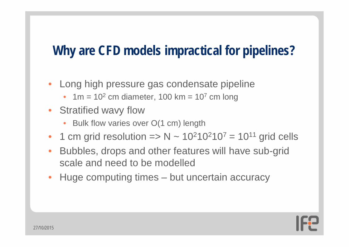
Why are CFD models impractical for pipelines?
• Long high pressure gas condensate pipeline• 1m = 102 cm diameter, 100 km = 107 cm long
• Stratified wavy flow• Bulk flow varies over O(1 cm) length
• 1 cm grid resolution => N ~ 102102107 = 1011 grid cells• Bubbles, drops and other features will have sub-grid
scale and need to be modelled• Huge computing times – but uncertain accuracy
27/10/2015