Location Updating Schemes for High-Speed Railway …€¦ · To take two user clusters clustering...
16
Hindawi Publishing Corporation Mathematical Problems in Engineering Volume 2012, Article ID 802152, 15 pages doi:10.1155/2012/802152 Research Article Location Updating Schemes for High-Speed Railway Cellular Communication Systems Hao Wu, Tao Wang, and Zhangdui Zhong State Key Laboratory of Rail Traffic Control and Safety, Beijing Jiaotong University, Beijing 100044, China Correspondence should be addressed to Hao Wu, [email protected] Received 11 January 2012; Accepted 20 February 2012 Academic Editor: Ming Li Copyright q 2012 Hao Wu et al. This is an open access article distributed under the Creative Commons Attribution License, which permits unrestricted use, distribution, and reproduction in any medium, provided the original work is properly cited. High-speed railway private cellular network provides voice and data services for passengers. It brings much signaling cost as a great many of mobile subscribers ask for location updating simul- taneously. Moreover, it leads to plenty of control signalingchannel requests. This paper presents two novel location updating schemes, that is, “clustering location management” and “mobile group location management” to solve the problems caused by the existing location updating scheme in high speed railway cellular private network. These two schemes can realize location up- dating without occupying more frequency resources. In addition, it does not impact the mobile subscribers’ paging. Then it analyses the performance of two improved schemes, such as channel request number of stand-alone dedicated control channel SDCCH, average waiting time of loca- tion updating, cost of location updating, and paging. The result indicates that both schemes can uti- lize the SDCCH channel resource effectively. 1. Introduction With the constructing and opening of the high-speed railway lines, mobile users’ demand of the voice, data, and other services in the high-speed train is gradually improved. Since the en- vironment of the radio propagation is very complex, and it executes handover frequently during the calling procedure, mobile users have some problems, such as low communication quality, and high call drop rate. Although it can be solved through the construction of private networks for the high-speed railways 1, 2, some new problems are involved correspond- ingly. For example, there are a large number of mobile users in the same train. All mobile users will send the location update messages to the network at the same time. As a result, the signaling overhead will be increased, and it will even cause the congestion of signaling chan- nel 3, 4. The field test data also confirmed this. It can be found that most congested base sta- tions locate at the border between the two location areas, and the congestion time is
Transcript of Location Updating Schemes for High-Speed Railway …€¦ · To take two user clusters clustering...

Hindawi Publishing CorporationMathematical Problems in EngineeringVolume 2012, Article ID 802152, 15 pagesdoi:10.1155/2012/802152
Research ArticleLocation Updating Schemes for High-SpeedRailway Cellular Communication Systems
Hao Wu, Tao Wang, and Zhangdui Zhong
State Key Laboratory of Rail Traffic Control and Safety, Beijing Jiaotong University, Beijing 100044, China
Correspondence should be addressed to Hao Wu, [email protected]
Received 11 January 2012; Accepted 20 February 2012
Academic Editor: Ming Li
Copyright q 2012 Hao Wu et al. This is an open access article distributed under the CreativeCommons Attribution License, which permits unrestricted use, distribution, and reproduction inany medium, provided the original work is properly cited.
High-speed railway private cellular network provides voice and data services for passengers. Itbrings much signaling cost as a great many of mobile subscribers ask for location updating simul-taneously. Moreover, it leads to plenty of control signaling channel requests. This paper presentstwo novel location updating schemes, that is, “clustering location management” and “mobilegroup location management” to solve the problems caused by the existing location updatingscheme in high speed railway cellular private network. These two schemes can realize location up-dating without occupying more frequency resources. In addition, it does not impact the mobilesubscribers’ paging. Then it analyses the performance of two improved schemes, such as channelrequest number of stand-alone dedicated control channel (SDCCH), average waiting time of loca-tion updating, cost of location updating, and paging. The result indicates that both schemes can uti-lize the SDCCH channel resource effectively.
1. Introduction
With the constructing and opening of the high-speed railway lines, mobile users’ demand ofthe voice, data, and other services in the high-speed train is gradually improved. Since the en-vironment of the radio propagation is very complex, and it executes handover frequentlyduring the calling procedure, mobile users have some problems, such as low communicationquality, and high call drop rate. Although it can be solved through the construction of privatenetworks for the high-speed railways [1, 2], some new problems are involved correspond-ingly. For example, there are a large number of mobile users in the same train. All mobileusers will send the location update messages to the network at the same time. As a result, thesignaling overhead will be increased, and it will even cause the congestion of signaling chan-nel [3, 4]. The field test data also confirmed this. It can be found that most congested base sta-tions locate at the border between the two location areas, and the congestion time is

2 Mathematical Problems in Engineering
concentrated within a brief period. Thus, in order to ensure the success of location update,more frequencies should be allocated even if the requirement of voice service in the privatenetwork is less. Obviously it is a waste of the network resources. In this paper, to reduce thecost of the location updating and improve the performance of communication system, wepropose “clustering location management” scheme and “mobile group location manage-ment” scheme used in mobile communication system for passenger dedicated lines, and itmay ensure the mobile users to execute location update successfully and not to affect the nor-mal paging process.
There are three types of approaches for location update procedure: time-based, move-ment-based, and distance-based update schemes [5]. Each type has its advantages suitablefor special applications. In order to improve the performance of location management, theimproved methods based on those schemes are proposed in the literatures [6–13], such ashybrid location update scheme [6], dynamic location management scheme based on move-ment-state [7], interoperation of identity management [8], and two-level pointer forwardingstrategy for location management in PCS networks [9]. According to the move trend of train,some mobile location management schemes have also been proposed. For instance, a methodwas proposed in [10], which divided the users into different groups based on their movespeed and used the corresponding location management scheme to improve paging ef-ficiency. In [11], a hybrid method based on self-organization mobile network and GSMnetwork has been presented, but the complexity of implementation is increased. Accordingto the characteristics of railway communication, a group location management method basedon the group ID (GID) and virtual visit location register (VVLR) is proposed in [12]. Tomeet the requirement of mobility of base-station in military communication, an enhancedmechanism for relay-based group mobility by extending the IEEE 802.16 m specification onrelay is proposed in [13]. However, the methods described in [12, 13] both need to add somemobile base-station equipments, and the internal communication in a group still occupied thenetwork resource, it brings a great challenge to the mobile communication network. Severallocation management strategies to reduce the cost of location management in mobile net-works are presented in [14–16].
For the above reasons, we propose two location update schemes not taking additionalfrequency resource, and the improved schemes may ensure all the users on the high-speedtrain to finish location update. For the specific application, we mainly consider two schemes.The first scheme is called “clustering location management” scheme, in which mobile userswill be divided into multiple groups to execute location update separately. The secondscheme considers the mobile users in a carriage as an integral unit (group), and a particulardevice (group head) executes location update as the representative of the whole group, whichis called “mobile group location management” scheme. This paper is organized as follows: inSection 2, the principles of two improved location schemes are described. In Section 3, thefurther analysis and performance comparison of the existing scheme and improved schemesare given. Finally the conclusion is obtained in Section 4.
2. Principle Description of Two Improved Schemes
2.1. Clustering Location Management Scheme
The basic idea of clustering location management (CLM) scheme is to divide the mobile sub-scribers (MSs) with high-speed movement into two or more clusters according to their

Mathematical Problems in Engineering 3
Movement direction of train The additional cell The additional cell
The additional cell Movement direction of train
The additional cell
of LALf of LAMf
of LAMb of LANb
LAM LANLAL
Cell L1 Cell L2 Cell Ll Cell M1 Cell M2 Cell Mm Cell N1 Cell N2 Cell Nn· · · · · · · · ·
Figure 1: location area and virtual location area.
identification, such as international mobile subscriber identity (IMSI), and then the MSs ineach cluster perform location updating in turns. Thus, it can reduce the number of MSs whoneed location updating in unit time, decreasing the network resource requirement. Mean-while, through the virtual location area, it can guarantee the paging of those MSs who havenot carried out the location updating yet, so as to reduce the call failure probability and im-prove the reliability of communication.
To take two user clusters clustering in GSM system as an example, according to thedifference number of the end bit of IMSI, the odd number MSs is clustering as Cluster 1, theeven number MSs is clustering as Cluster 2. When mobile stations find that the current loca-tion area code (LAC) is different from the previous registered LAC, they will request a loca-tion updating. Considering the different clusters, the network side let the MSs of Cluster1 carry out the normal location updating procedure, but the updating request of the MSs ofCluster 2 will not be accepted temporarily. After the timer reaches the default time T , then theMSs of Cluster 2 perform the location updating procedure. The value of the default time Tis related with the speed of train and the cell radius, T should not be longer than the traintravel time for a cell, namely, it should guarantee the MSs of Cluster 1 to complete the locationupdating within T .
Considering the network coverage along the railway is linear in general, as shown inFigure 1, supposed that LAL, LAM, and LAN are three adjacent location areas, which are l cellsin LAL, m cells in LAM, and n cells in LAN. After adopting the CLM scheme, during the loca-tion updating phase of Cluster 1, if the MS in Cluster 2 has an incoming call, it will be miss-ed because the MSs in Cluster 2 have not performed location updating yet. Hence, we putforward a concept of virtual location area for paging the MSs in Cluster 2 during Cluster 1 up-dating phase. The virtual location areas are recorded in the database of network side, and itcontains all cells in the original location area and adds an adjacent cell, which is in the targetlocation area. In this case, if the MS in Cluster 2 has an incoming call, it will page MSs in thevirtual location area. As shown in Figure 1, when the train travels from left to right, LALf,which is the virtual location area of LAL, is defined as all cells in LALand cell M1, and LAMf,
which is the virtual location area of LAM, is defined as all cells in LAM and cell N1. Similarly,when the train travels from right to left, LAMb, which is the virtual location area of LAM, isdefined as all cells in LAM and cell L1, and LANb, which is the virtual location area of LAN, isdefined as all cells in LAM and cell Mm.
By use of the virtual location area, the MSs who are waiting for location updating willnot miss the incoming calls. For example, when MSs move from LAM into LAN, before thetimer time t reaches the default time T , the MSs of Cluster 2 are located in cell N1, which

4 Mathematical Problems in Engineering
MSC/VLR
HLR
BSC
BTS
MGH
Dual-modeMT
Dual-modeMT
Dual-modeMT
Dual-modeMT
WLAN radioaccess
Carriage n
Carriage n
GSM radio access
Non-dual-mode MT· · · · · ·
Figure 2: Network architecture of the group location management.
belongs to LAN, but their location information is still LAM; when the MS of Cluster 2 has anincoming call, the network will page the MS in the virtual location area LAMf, including cellM1, M2, . . ., Mm and cell N1, so the called MS will not miss the incoming call. Note that thepaging procedure of the MSs in Cluster 2 is as usual.
If the number of MSs is very large, to avoid the call failure caused by too many locationupdates, the MSs can be divided into more clusters, each cluster carries out the location up-dating procedure in turns. However, the virtual location areas for each cluster must be rede-fined, the specific rules of which can be decided by the network operators.
2.2. Mobile Group Location Management Scheme
To implement the mobile group location management (MGLM) scheme, we need to configuresome network devices in each railway carriage to build WLANs, as shown in Figure 2. EachWLAN’s coverage range is limited within a carriage, and it should be equipped with adevice as the mobile group head (MGH), which is responsible for the management of mobileterminals and performs the integrated location updating with representing the group. MGHcomprises a wireless access point (AP), a cellular communication transceiver, and MGH re-gister for storage the registered information of group members, as shown in Figure 3. Themobile terminals have dual mode, which means they support both cellular network wirelesstransceiver function and Wi-Fi function; hence, they have the ability to access to the WLAN.
In our MGLM scheme, we take GSM network as an example. It includes several pro-cesses: the group formation, dissolution and update process, intramobile switching center/visitor location register (MSC/VLR) group location updating procedure, inter-MSC/VLRgroup location updating procedure. As for the group location updating, it is in relative termsof traditional GSM location updating, the traditional GSM location updating is requestedby MSs, each update just updates one MS’s information, but the group location updating is

Mathematical Problems in Engineering 5
GSM transceiver
Register of MGH
WLANAP
Figure 3: The inner structure of the mobile group head.
requested by the MGH, and it may update the location information of all MSs managed by theMGH. Apparently, the updating efficiency of MGLM scheme is much higher than the tradi-tional ways. The details of those processes are as follows.
2.2.1. Group Formation, Dissolution, and Update Process
As the train sets off from the origin station, the WLANs in the carriages are enabled, the AP inMGH periodically sends member-joining notification message to MSs, the MSs in the carriageestablish association with AP through the WLAN and are formed as an integral unit (group).The MGH is taken as the whole group representative, and the ordinary MSs are regarded asthe group members. The specific process related to group formation, dissolution, and updateincludes the following steps.
(1) The AP in MGH sends the checking signal with a period of TAP in the wirelesscoverage range, usually inside a railway carriage. Mobile group head register storesevery MS’s IMSI number or temporary mobile subscriber identity (TMSI) number,each TMSI is correspondent to an IMSI;
(2) When the mobile terminals (MTs) within WLAN signal coverage range receives thechecking signal, they reply their own IMSI (or TMSI) number, and then apply forjoining the group;
(3) After receiving the reply of each MS, the MGH registers the IMSI (or TMSI) num-ber and sequence number of each MS, then returns a confirmation message and seq-uence number to the MS; when the MS receives the confirmation message, it meansthat MS has joined the group and knows its sequence number in the group;
(4) MGH checks the change of member in the carriage every TAP cycle regularly, whenMGH finds new member joining the group, it registers the new MS information andreturns the corresponding message and sequence number;
(5) After sending the period checking signal, if the MGH has not received the IMSI (orTMSI), it thinks that the MS has left the group and then cancels the MS group regi-stration information.
2.2.2. Intra-MSC/VLR Group Location Updating Procedure [17]
The intra-MSC/VLR group location updating procedure is shown in Figure 4.

6 Mathematical Problems in Engineering
1
Channel request
Immediate assignment
Location updatingrequest
22
2
333
4
Transfer new TMSI
TMSI reallocation complete
5
TMSI reallocation complete/location
updating failure
6
7. Set UPDATED status and storage
the new LAI
66
Location updatingaccept
MGH BTS BSC MSC/VLRMS
Figure 4: Intra-MSC/VLR group location updating procedure.
(1) The MGH sends the “channel request” message to BTS on random access channel(RACH), the priority of this message is higher than those sent from the ordinaryMSs’, so the base station (BTS) responds to the “immediate assignment” messageon a stand-alone dedicated control channel (SDCCH);
(2) The MGH sends the “location updating request” message to the network, which in-cludes each MS’s IMSI (or TMSI) number and old location area identify (LAI) insequence. The location updating request is forwarded to the MSC/VLR;
(3) The VLR stores each MS’s new LAI, assigns a new TMSI to each MS, and then sendsthe new TMSI table aligned in sequence via “location updating accept” message tothe MGH;
(4) The MGH receives the new TMSI table and forwards the message including the newMS’s TMSI via WLAN, then each MS updates its location information and TMSI;
Mathematical Problems in Engineering 7
(5) The MSs in the group replies the “TMSI reallocation complete” acknowledgementmessage to the MGH through the WLAN, if the MGH does not receive the acknow-ledgement message of some MS, the MS location updating failure is considered;
(6) The MGH replies back “TMSI reallocation complete” or “location updating failure”message of each MS to the network in sequence, MSC receives the message andreleases the channel link. For the MSs failed in location updating, the networkresponds their “location updating message” messages sent to the BTS individually,the location updating procedure is the same as the traditional one;
(7) After completing the location updating, the mobile station sets SIM card’s updatestatus to UPDATED (latest) and storages the new LAI.
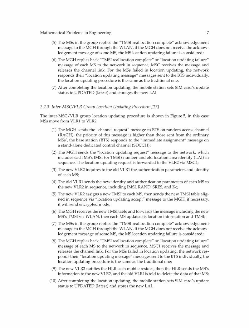
2.2.3. Inter-MSC/VLR Group Location Updating Procedure [17]
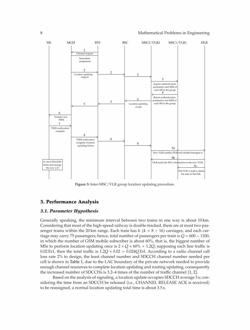
The inter-MSC/VLR group location updating procedure is shown in Figure 5, in this caseMSs move from VLR1 to VLR2.
(1) The MGH sends the “channel request” message to BTS on random access channel(RACH), the priority of this message is higher than those sent from the ordinaryMSs’, the base station (BTS) responds to the “immediate assignment” message ona stand-alone dedicated control channel (SDCCH);
(2) The MGH sends the “location updating request” message to the network, whichincludes each MS’s IMSI (or TMSI) number and old location area identify (LAI) insequence. The location updating request is forwarded to the VLR2 via MSC2;
(3) The new VLR2 inquires to the old VLR1 the authentication parameters and identityof each MS;
(4) The old VLR1 sends the new identity and authentication parameters of each MS tothe new VLR2 in sequence, including IMSI, RAND, SRES, and Kc;
(5) The new VLR2 assigns a new TMSI to each MS, then sends the new TMSI table alig-ned in sequence via “location updating accept” message to the MGH, if necessary,it will send encrypted mode;
(6) The MGH receives the new TMSI table and forwards the message including the newMS’s TMSI via WLAN, then each MS updates its location information and TMSI;
(7) The MSs in the group replies the “TMSI reallocation complete” acknowledgementmessage to the MGH through the WLAN, if the MGH does not receive the acknow-ledgement message of some MS, the MS location updating failure is considered;
(8) The MGH replies back “TMSI reallocation complete” or “location updating failure”message of each MS to the network in sequence, MSC1 receives the message andreleases the channel link. For the MSs failed in location updating, the network res-ponds their “location updating message” messages sent to the BTS individually, thelocation updating procedure is the same as the traditional one;
(9) The new VLR2 notifies the HLR each mobile resides, then the HLR sends the MS’sinformation to the new VLR2, and the old VLR1is told to delete the data of that MS;
(10) After completing the location updating, the mobile station sets SIM card’s updatestatus to UPDATED (latest) and stores the new LAI.
8 Mathematical Problems in Engineering
MS
1Channel request
Immediate assignment
Location updatingrequest
22
2
Location updatingaccept
55
5
6Transfer new
TMSI
TMSI reallocation complete
7
TMSI reallocation complete/location
updating failure
8
10. Set UPDATED status and storage
the new LAI
Inquire authentication parameters and IMSI of
each MS in the group
3
4Return authentication
parameters and IMSI of each MS in the group
88
9aNew VLR2 notifies HLR each mobile belonged to
Old VLR1 is told to delete the data of that MS
9b
9c
MGH BSC MSC2/VLR2 MSC1/VLR1 HLRBTS
HLR sends the MS’s information to the new VLR2
Figure 5: Inter-MSC/VLR group location updating procedure.
3. Performance Analysis
3.1. Parameter Hypothesis
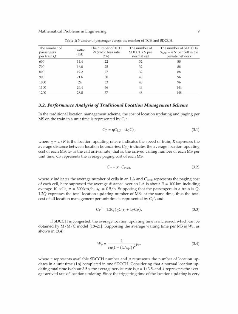
Generally speaking, the minimum interval between two trains in one way is about 10 km.Considering that most of the high-speed railway is double-tracked, there are at most two pas-senger trains within the 20 km range. Each train has k (k = 8 ∼ 16) carriages, and each car-riage may carry 75 passengers; hence, total number of passengers per train is Q = 600 ∼ 1200,in which the number of GSM mobile subscriber is about 60%, that is, the biggest number ofMSs to perform location updating once is 2 × Q × 60% = 1.2Q; supposing each line traffic is0.02 Er1, then the total traffic is 1.2Q × 0.02 = 0.024QErl. According to a radio channel callloss rate 2% to design, the least channel number and SDCCH channel number needed percell is shown in Table 1, due to the LAC boundary of the private network needed to provideenough channel resources to complete location updating and routing updating, consequentlythe increased number of SDCCHs is 3.2–4 times of the number of traffic channel [1, 2].
Based on the analysis of signaling, a location update occupies SDCCH average 3 s; con-sidering the time from an SDCCH be released (i.e., CHANNEL RELEASE ACK is received)to be reassigned, a normal location updating total time is about 3.5 s.
Mathematical Problems in Engineering 9
Table 1: Number of passenger versus the number of TCH and SDCCH.
The number ofpassengersper train Q
Traffic(Erl)
The number of TCHN(radio loss rate
2%)
The number ofSDCCHs S per
normal cell
The number of SDCCHsSLAC = 4N per cell in the
private network
600 14.4 22 32 88700 16.8 25 32 88800 19.2 27 32 88900 21.6 30 40 961000 24 33 40 961100 26.4 36 48 1441200 28.8 37 48 148
3.2. Performance Analysis of Traditional Location Management Scheme
In the traditional location management scheme, the cost of location updating and paging perMS on the train in a unit time is represented by CT :
CT = ηCLU + λCCP , (3.1)
where η = v/R is the location updating rate; v indicates the speed of train; R expresses theaverage distance between location boundaries; CLU indicates the average location updatingcost of each MS; λC is the call arrival rate, that is, the arrived calling number of each MS perunit time; CP represents the average paging cost of each MS:
CP = x · CPcell, (3.2)
where x indicates the average number of cells in an LA and CPcell represents the paging costof each cell, here supposed the average distance over an LA is about R = 100 km includingaverage 10 cells, v = 300 km/h, λC = 0.5/h. Supposing that the passengers in a train is Q,1.2Q expresses the total location updating number of MSs at the same time, thus the totalcost of all location management per unit time is represented by CT
′, and
CT′ = 1.2Q
(ηCLU + λCCP
). (3.3)
If SDCCH is congested, the average location updating time is increased, which can beobtained by M/M/C model [18–21]. Supposing the average waiting time per MS is Wq, asshown in (3.4):
Wq =1
cμ(1 − (λ/cμ
))2pc, (3.4)
where c represents available SDCCH number and μ represents the number of location up-dates in a unit time (1 s) completed in one SDCCH. Considering that a normal location up-dating total time is about 3.5 s, the average service rate is μ = 1/3.5, and λ represents the aver-age arrived rate of location updating. Since the triggering time of the location updating is very

10 Mathematical Problems in Engineering
short, we suppose that all MSs start location updating procedure within 1 min, λ = 1.2Q/60.pc and the traffic degree ρ are related to SDCCH number c and the steady-state probabilityp0:
pc =1c!
· ρc · p0,
ρ =λ
μ,
p0 =
[c−1∑
k=0
1k!ρk =
ρc
c!(1 − ρc)
]−1
,
ρc =λ
cμ< 1,
(3.5)
where k represents the number of MSs, that is, 1.2Q, from the above equations, the numberof MSs is more, the number of SDCCHs is less, thus the SDCCH is more congested, and theaverage waiting time of MS for location updating is much longer.
3.3. Performance Analysis of CLM Scheme
In the improved CLM scheme, MSs are divided into n clusters. The cost of the location updat-ing is the same as the cost of traditional location management scheme, although the cost ofpaging is increased, the performance of radio resource utilization rate and the average wait-ing time of location updating is improved. Please refer to [22–25]:
CLU
CPcell= 17. (3.6)
As we know, the cost of location updating occupies too much proportion of the totalcost of location management; therefore, a little increase of paging cost will bring little effect tothe total cost of location management. Supposing CPcell is the unit cost, we may calculate CLU
and CP via formulas (3.6) and (3.2), respectively; moreover, we may analyze the cost of thelocation updating and the cost of paging and the total cost.
Through clustering, the number of SDCCHs can be reduced greatly. From Figure 6, wecan see that the CLM scheme with 48 SDCCHs can acquire the similar waiting time perfor-mance of traditional scheme with 88 SDCCHs, which reduces a great amount of the SDCCHchannel consumption. And the more the number of the SDCCH is, the shorter the averagewaiting time is. Observed in Figure 6, we may choose the appropriate number of SDCCHs tobe assigned. When n = 1, which means no clustering, it needs at least 88 SDCCHs [1]; whenn = 2, the number of SDCCHs can be set to 48; when n = 3, the number of SDCCHs can beset to 40; when n = 4, the number of SDCCHs can be just set to 32. Hence, it can greatly re-duce the SDCCH channel resource by clustering and further enhance the QoS quality of MSs.Using the same number of SDCCHs, the more clusters in CLM, the shorter the average wait-ing time is. For example when SDCCH = 88, the average waiting time of the traditionalscheme (i.e., n = 1) is 0.215653 s, and when SDCCH = 56, the average waiting time of CLM forn = 2 is just 0.15365 s, consequently, the CLM scheme can achieve a better performance.

Mathematical Problems in Engineering 11
0
0.05
0.1
0.15
0.2
0.25
0.3
0.35
0.4
Ave
rage
wai
ting
tim
e of
Number of SDCCH
30 40 50 60 70 80 90 100 110
n = 1n = 2
n = 3n = 4
loca
tion
upd
atin
g/us
er/
s
Figure 6: The average waiting time of location updating.
0
0.2
0.4
0.6
0.8
1
Cos
t of l
ocat
ion
upd
atin
g
600 700 800 900 1000 1100 1200Average passengers in a train (Q)
n = 1, c = 88n = 2, c = 48
n = 2, c = 56n = 3, c = 48
Figure 7: The cost of location updating (n represents the number of clusters, c represents the number ofSDCCHs).
Figure 7 describes the performance comparison of the cost of the location updating bet-ween traditional scheme and the CLM scheme. Seen from the graph, no matter whether clus-tering, the general trend of the location updating cost is increased as the number of MSs.When no clustering (i.e., n = 1), if the number of MSs is less than 850, the updating cost isa little better than CLM scheme, but its number of SDCCHs far outweighs the CLM scheme;whereas when the total passengers is nearly 1200, the cost of location updating for no clus-tering increases significantly. When using the same number SDCCH, the more clusters;

12 Mathematical Problems in Engineering
3500
4000
4500
5000
5500
6000
6500
7000
7500
8000
600 700 800 900 1000 1100 1200Average passengers in a train (Q)
n = 1n = 2
n = 3n = 4
Cos
t of p
agin
g(C
P)
Figure 8: The cost of paging.
3
4
5
6
7
8
Tot
al c
ost o
f loc
atio
n m
anag
emen
t(C
T)
600 700 800 900 1000 1100 1200Average passengers in a train (Q)
Traditional schemeCLM n = 2MGLM d = 0.1
MGLM d = 0.5MGLM d = 1
×104
Figure 9: The total cost comparison of the three location management schemes.
the less cost of location updating. When using the same number of clusters n, the moreSDCCHs are assigned, the less cost of location updating is.
Figure 8 is the paging cost performance comparison between the traditional schemeand the CLM scheme. We can see that the more clusters, the higher paging cost is increased,but usually the value of n could be 2 or 3 in practical application, and the paging cost only oc-cupies a small proportion of the cost of location management.

Mathematical Problems in Engineering 13
Hence, it can be concluded that on the basis of saving SDCCH resource, the CLMscheme can acquire the similar average waiting time and total location management cost per-formance of the traditional scheme.
3.4. Performance Analysis of MGLM Scheme
In MGLM scheme, we suppose that there are d ∗ 1.2Q (0 < d < 1) MSs with dual-mode ter-minals joining into the group, the other users cannot join into the group due to mobility orwithout dual-mode terminals. The definition Q is the same as 3.2; d represents the proportionof MSs in the group. According to the basic principle of the MGLM scheme, the decreasingpercentage of SDCCH is in proportion to the percentage of MSs joining in the group, for in-stance, when d = 0.5, the amount of SDCCHs is decreased from 88 to 44. However whend > 0.5, to meet the requirement of calling, the number of SDCCHs is not suitable for de-creasing. From the specific procedure of the MGLM scheme, we know the overhead of theMGLM scheme includes the overhead of the initial group registration procedure Cg , the over-head of the group location updating procedure CLU G, the overhead of paging CP , and theoverhead of group cancellation procedure Cc. Since the group registration does not involvethe mobile network resources, it will be neglected, and the group cancellation procedure canbe equivalent to the cost of a location updating. Assuming there are 75 passengers in each car-riage, where 75d MSs with the dual-mode terminal join the group update management, hencethe cost of location updating includes two parts: the cost of dual-mode users CLU G and thecost of ordinary users CLU. The calculation of the LA cost for ordinary users is the same as thecalculation in traditional scheme, to see (3.6); the LA cost of other dual-mode users can bederived by the signaling:
CLU G
CPcell≈ 12.36. (3.7)
Hence, the total cost of MGLM is
CT G′ = 1.2Q · d · (η + 1
)CLU G + 1.2Q · (1 − d) · ηCLU + 1.2Q · λcCP , (3.8)
where the cost of paging Cp is the same as the one in the traditional management scheme.The cost of the location management comparison is depicted in Figure 9.
Figure 9 shows that the total cost of the CLM is higher than the tradition scheme’s, thisis because the virtual paging area introduced by CLM leads to the increase of paging cost.Whereas the total cost of the MGLM is relatively low, and with the number increase of MSsjoining in the group, its total cost decreases more and more. The reason is that the grouplocation updating may reduce the updating cost greatly. Obviously, we do not consider theequipment cost in MGLM in this paper.
4. Conclusions
In this paper, two kinds of location updating schemes for high-speed railway private networkare provided, that is, clustering location management (CLM) and mobile group location man-agement (MGLM). The performance analysis and comparison results of traditional scheme,

14 Mathematical Problems in Engineering
CLM and MGLM schemes are also given. From the results we may conclude that both thetwo improved location updating schemes can reduce the number of SDCCHs greatly. For ex-ample, with CLM scheme, it may decrease the number of location updating per unit timemore than 50%, and it can acquire much better performance with 56 SDCCHs than traditionalscheme with 88 SDCCHs. Consequently, it saves the SDCCH resource greatly. Meanwhile,through adopting the virtual location area, it can guarantee the paging of MSs and reduce thecall failure probability and improve the reliability of communication. However, the CLMscheme may increase the complexity of network management. From the view of decreasingradio resource and the cost of location updating, the MGLM scheme is the best choice, inwhich the decreasing extent of SDCCH is related with the percentage of MSs joining in thegroup, for instance, when d = 0.5, the amount of SDCCHs is decreased from 88 to 44. Since themembers of carriage can perform group location updating by the MGH, the cost of the loca-tion updating is decreased greatly; but it needs to add the MGH device in each carriage andleads to much change in both the network side and the mobile terminals, the complexity ofMGLM is the highest in 3 schemes. In conclusion, the railway private cellular network operat-or may take a suitable location management improved scheme to decrease the location updat-ing average waiting time and utilize the radio resource effectively.
Acknowledgment
This paper is supported by the State Key Laboratory of Rail Traffic Control and Safety (Con-tract no. RCS2010ZZ004), Beijing Jiaotong University. This paper is also supported by Pro-gram for Changjiang Scholars and Innovative Research Team in University under Grant no.IRT0949 and the Joint State Key Program of the National Natural Science Foundation of Chinaand the National Railway Ministry of China (Grant no. 60830001). And it is supported in partby the Chinese National Programs for High Technology Research and Development (863)Project 2009AA110302.
References
[1] Y. Wei-guang, G. Hai-ping, and H. Hin-yang, “Discussion about the private network planning and op-timazation of high-speed railway,” Telecommunications Science, vol. 22, no. 3, pp. 94–98, 2008 (Chinese).
[2] L. Fu-xin, X. Ying, and L. Wen-peng, “Study on mobile network coverage scheme of high speedrailway,” Designning Techniques of Posts and Telecommunications, vol. 22, no. 9, pp. 20–24, 2008(Chinese).
[3] Y. Zhang and M. Fujise, “Location management congestion problem in wireless networks,” IEEETransactions on Vehicular Technology, vol. 56, no. 2, pp. 942–954, 2007.
[4] M. Li and W. Zhao, “Visiting power laws in cyber-physical networking systems,” Mathematical Pro-blems in Engineering, vol. 2012, Article ID 302786, 13 pages, 2012.
[5] N. E. Kruijt, D. Sparreboom, F. C. Schoute, and R. Prasad, “Location management strategies for cell-ular mobile networks,” Electronics and Communication Engineering Journal, vol. 10, no. 2, pp. 64–72,1998.
[6] G. Y. Lee, Y. Lee, and Z. J. Haas, “Hybrid location-update scheme for mobile networks,” IEEE Transactions on Vehicular Technology, vol. 58, no. 1, pp. 338–348, 2009.
[7] C. Peng, Y. Xue-jun, and H. Zai-lu, “A dynamic location management scheme based on movement-state,” ACTA Telectronica Sinica, vol. 30, no. 7, pp. 1038–1040, 2002 (Chinese).
[8] J. Chen, G. Wu, and Z. Ji, “Secure interoperation of identity managements among different circles oftrust,” Computer Standards and Interfaces, vol. 33, no. 6, pp. 533–540, 2011.
[9] W. Ma and Y. Fang, “Two-level pointer forwarding strategy for location management in PCS net-works,” IEEE Transactions on Mobile Computing, vol. 1, no. 1, pp. 32–45, 2002.

Mathematical Problems in Engineering 15
[10] Y. W. Chung, “Performance analysis of movement-based group location management for mobile sta-tions riding on transportation systems in cellular systems,” in Proceedings of the 11th IEEE/IPSJ Inter-national Symposium on Applications and the Internet (SAINT ’11), pp. 333–337, Munich, Germany, 2011.
[11] W. Fu-Rong, X. Lai, and W. Hao, “A group location management method based on hybird mobilenetwork,” People’s Republic of China: ZL101001414A, July, 2007.
[12] I. Han and D.-H. Cho, “Group location management for mobile subscribers on transportation systemsin mobile communication networks,” IEEE Transactions on Vehicular Technology, vol. 53, no. 1, pp. 181–191, 2004.
[13] R. Balakrishnan, X. Yang, M. Venkatachalam, and I. F. Akyildiz, “Mobile relay and group mobility for4G WiMAX networks,” in Proceedings of the IEEE Wireless Communications and Networking Conference(WCNC ’11), pp. 1224–1229, Quintana Roo, Mexico, March 2011.
[14] Z. Mao, “An intra-LA location update strategy for reducing paging cost,” IEEE CommunicationsLetters, vol. 6, no. 8, pp. 334–336, 2002.
[15] P. G. Escalle, V. C. Giner, and J. M. Oltra, “Reducing location update and paging costs in a PCS net-work,” IEEE Transactions on Wireless Communications, vol. 1, no. 1, pp. 200–208, 2002.
[16] R. Munadi, M. Ismail, M. Abdullah, and N. Misran, “Location management cost reduction usingfuzzy logic in cellular radio network,” in Proceedings of the IEEE International Conference on Space Scienceand Communication (IconSpace ’11), pp. 165–169, Penang, Malaysia, 2011.
[17] GSM 03.12, Digital cellular telecommunications system (Phase 2+); Location registration procedures,1995.
[18] S. V. Subramanian and R. Dutta, “Performance measurements and analysis of M/M/C queuingmodel based sip proxy servers in local and wide area networks,” in Proceedings of the 2nd InternationalConference on Advances in Recent Technologies in Communication and Computing (ARTCom ’10), pp. 306–310, Kerala, India, October 2010.
[19] M. Li and W. Zhao, “Representation of a stochastic traffic bound,” IEEE Transactions on Parallel andDistributed Systems, vol. 21, no. 9, pp. 1368–1372, 2010.
[20] M. Li, C. Cattani, and S. Y. Chen, “Viewing sea level by a one-dimensional random function with longmemory,” Mathematical Problems in Engineering, vol. 2011, Article ID 654284, 13 pages, 2011.
[21] G. Ren-yong, “A rule of updating position in microscopic pedestrian model,” in Proceedings of theInternational Conference on Optoelectronics and Image Processing (ICOIP ’10), vol. 1, pp. 120–123, Haiko,China, November, 2010.
[22] E. Martin, G. Lin, M. Weber, P. Pesti, and M. Woodward, “Unified analytical models for location man-agement costs and optimum design of location areas,” in Proceedings of the 5th International Conferenceon Collaborative Computing: Networking, Applications and Worksharing (CollaborateCom ’09), pp. 1–10,IEEE Press, Washington, DC, USA, November 2009.
[23] Z. Liao, S. Hu, and W. Chen, “Determining neighborhoods of image pixels automatically for adaptiveimage denoising using nonlinear time series analysis,” Mathematical Problems in Engineering, vol. 2010,Article ID 914564, 14 pages, 2010.
[24] W.-S. Chen, P. C. Yuen, and X. Xie, “Kernel machine-based rank-lifting regularized discriminant anal-ysis method for face recognition,” Neurocomputing, vol. 74, no. 17, pp. 2953–2960, 2011.
[25] J. Yang, Z. Chen, W.-S. Chen, and Y. Chen, “Robust affine invariant descriptors,” Mathematical Problemsin Engineering, vol. 2011, Article ID 185303, 15 pages, 2011.

Submit your manuscripts athttp://www.hindawi.com
Hindawi Publishing Corporationhttp://www.hindawi.com Volume 2014
MathematicsJournal of
Hindawi Publishing Corporationhttp://www.hindawi.com Volume 2014
Mathematical Problems in Engineering
Hindawi Publishing Corporationhttp://www.hindawi.com
Differential EquationsInternational Journal of
Volume 2014
Applied MathematicsJournal of
Hindawi Publishing Corporationhttp://www.hindawi.com Volume 2014
Probability and StatisticsHindawi Publishing Corporationhttp://www.hindawi.com Volume 2014
Journal of
Hindawi Publishing Corporationhttp://www.hindawi.com Volume 2014
Mathematical PhysicsAdvances in
Complex AnalysisJournal of
Hindawi Publishing Corporationhttp://www.hindawi.com Volume 2014
OptimizationJournal of
Hindawi Publishing Corporationhttp://www.hindawi.com Volume 2014
CombinatoricsHindawi Publishing Corporationhttp://www.hindawi.com Volume 2014
International Journal of
Hindawi Publishing Corporationhttp://www.hindawi.com Volume 2014
Operations ResearchAdvances in
Journal of
Hindawi Publishing Corporationhttp://www.hindawi.com Volume 2014
Function Spaces
Abstract and Applied AnalysisHindawi Publishing Corporationhttp://www.hindawi.com Volume 2014
International Journal of Mathematics and Mathematical Sciences
Hindawi Publishing Corporationhttp://www.hindawi.com Volume 2014
The Scientific World JournalHindawi Publishing Corporation http://www.hindawi.com Volume 2014
Hindawi Publishing Corporationhttp://www.hindawi.com Volume 2014
Algebra
Discrete Dynamics in Nature and Society
Hindawi Publishing Corporationhttp://www.hindawi.com Volume 2014
Hindawi Publishing Corporationhttp://www.hindawi.com Volume 2014
Decision SciencesAdvances in
Discrete MathematicsJournal of
Hindawi Publishing Corporationhttp://www.hindawi.com
Volume 2014
Hindawi Publishing Corporationhttp://www.hindawi.com Volume 2014
Stochastic AnalysisInternational Journal of