
Link Layer Services Link Layer Services (more) · · 2003-04-09• Q: why both link-level and...
14
5: DataLink Layer 5a-1 14: Ethernet, Hubs, Bridges, Switches, Other Technologies used at the Link Layer, ARP Last Modified: 4/9/2003 1:14:12 PM 5: DataLink Layer 5a-2 Link Layer: Implementation ❒ Typically, implemented in “adapter” ❍ e.g., PCMCIA card, Ethernet card ❍ typically includes: RAM, DSP chips, host bus interface, and link interface application transport network link physical network link physical M M M M Ht Ht Hn Ht Hn Hl M Ht Hn Hl frame phys. link data link protocol adapter card 5: DataLink Layer 5a-3 Link Layer Services ❒ Framing, link access: ❍ encapsulate datagram into frame, adding header, trailer ❍ implement channel access if shared medium, ❍ ‘physical addresses’ used in frame headers to identify source, dest • different from IP address! ❒ Reliable delivery between two physically connected devices: ❍ we learned how to do reliable delivery over an unreliable link ❍ seldom used on low bit error link (fiber, some twisted pair) ❍ wireless links: high error rates • Q: why both link-level and end-end reliability? 5: DataLink Layer 5a-4 Link Layer Services (more) ❒ Flow Control: ❍ pacing between sender and receivers ❒ Error Detection: ❍ errors caused by signal attenuation, noise. ❍ receiver detects presence of errors: • signals sender for retransmission or drops frame ❒ Error Correction: ❍ receiver identifies and corrects bit error(s) without resorting to retransmission 5: DataLink Layer 5a-5 LAN technologies Data link layer so far: ❍ services, error detection/correction, multiple access Next: LAN technologies ❍ Ethernet ❍ hubs, bridges, switches ❍ 802.11 ❍ PPP ❍ ATM 5: DataLink Layer 5a-6 Ethernet “dominant” LAN technology: ❒ cheap $20 for 100Mbs! ❒ first widely used LAN technology ❒ Simpler, cheaper than token LANs and ATM ❒ Kept up with speed race: 10, 100, 1000 Mbps Metcalfe’s Ethernet sketch
Transcript of Link Layer Services Link Layer Services (more) · · 2003-04-09• Q: why both link-level and...
1
5: DataLink Layer 5a-1
14: Ethernet, Hubs, Bridges, Switches, Other Technologies used at the Link Layer, ARP
Last Modified: 4/9/2003 1:14:12 PM
5: DataLink Layer 5a-2
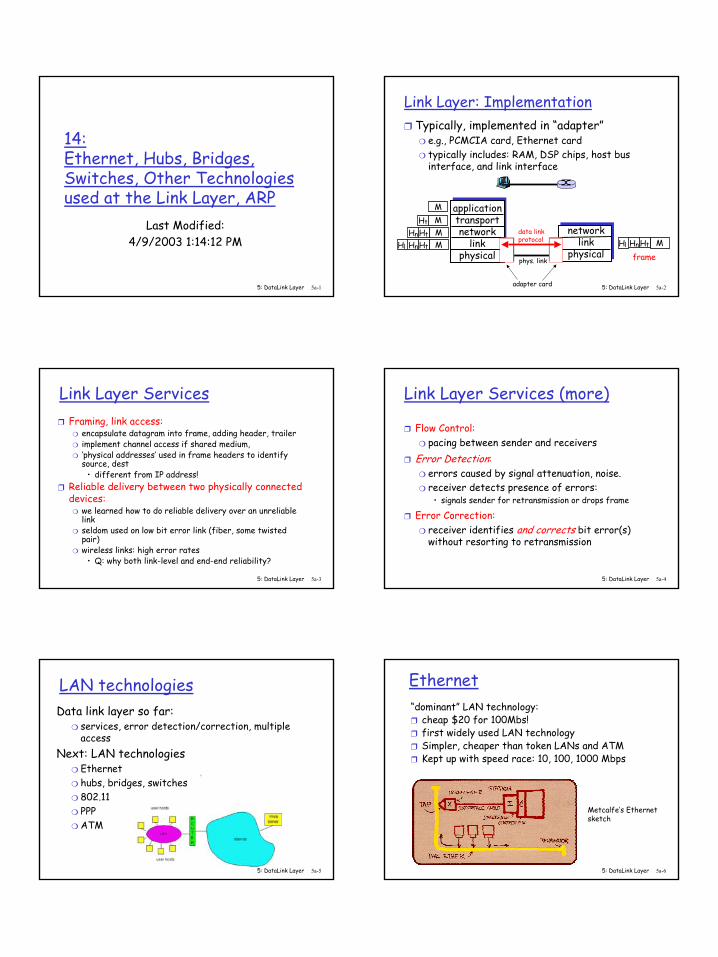
Link Layer: Implementation❒ Typically, implemented in “adapter”
❍ e.g., PCMCIA card, Ethernet card ❍ typically includes: RAM, DSP chips, host bus
interface, and link interface
applicationtransportnetwork
linkphysical
networklink
physical
MMMM
Ht
HtHn
HtHnHl MHtHnHl
framephys. link
data linkprotocol
adapter card
5: DataLink Layer 5a-3
Link Layer Services❒ Framing, link access:
❍ encapsulate datagram into frame, adding header, trailer❍ implement channel access if shared medium, ❍ ‘physical addresses’ used in frame headers to identify
source, dest • different from IP address!
❒ Reliable delivery between two physically connected devices:
❍ we learned how to do reliable delivery over an unreliable link
❍ seldom used on low bit error link (fiber, some twisted pair)
❍ wireless links: high error rates• Q: why both link-level and end-end reliability?
5: DataLink Layer 5a-4
Link Layer Services (more)
❒ Flow Control:❍ pacing between sender and receivers
❒ Error Detection:❍ errors caused by signal attenuation, noise. ❍ receiver detects presence of errors:
• signals sender for retransmission or drops frame
❒ Error Correction:❍ receiver identifies and corrects bit error(s)
without resorting to retransmission
5: DataLink Layer 5a-5
LAN technologiesData link layer so far:
❍ services, error detection/correction, multiple access
Next: LAN technologies❍ Ethernet❍ hubs, bridges, switches❍ 802.11❍ PPP❍ ATM
5: DataLink Layer 5a-6
Ethernet“dominant” LAN technology: ❒ cheap $20 for 100Mbs!❒ first widely used LAN technology❒ Simpler, cheaper than token LANs and ATM❒ Kept up with speed race: 10, 100, 1000 Mbps
Metcalfe’s Ethernetsketch
2
5: DataLink Layer 5a-7
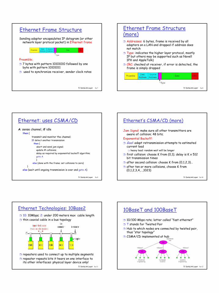
Ethernet Frame StructureSending adapter encapsulates IP datagram (or other
network layer protocol packet) in Ethernet frame
Preamble:❒ 7 bytes with pattern 10101010 followed by one
byte with pattern 10101011❒ used to synchronize receiver, sender clock rates
5: DataLink Layer 5a-8
Ethernet Frame Structure (more)❒ Addresses: 6 bytes, frame is received by all
adapters on a LAN and dropped if address does not match
❒ Type: indicates the higher layer protocol, mostly IP but others may be supported such as Novell IPX and AppleTalk)
❒ CRC: checked at receiver, if error is detected, the frame is simply dropped
5: DataLink Layer 5a-9
Ethernet: uses CSMA/CDA: sense channel, if idle
then {transmit and monitor the channel; If detect another transmission
then { abort and send jam signal; update # collisions; delay as required by exponential backoff algorithm; goto A}
else {done with the frame; set collisions to zero}}
else {wait until ongoing transmission is over and goto A}
5: DataLink Layer 5a-10
Ethernet’s CSMA/CD (more)
Jam Signal: make sure all other transmitters are aware of collision; 48 bits;
Exponential Backoff:❒ Goal: adapt retransmission attempts to estimated
current load❍ heavy load: random wait will be longer
❒ first collision: choose K from {0,1}; delay is K x 512 bit transmission times
❒ after second collision: choose K from {0,1,2,3}…❒ after ten or more collisions, choose K from
{0,1,2,3,4,…,1023}
5: DataLink Layer 5a-11
Ethernet Technologies: 10Base2❒ 10: 10Mbps; 2: under 200 meters max cable length❒ thin coaxial cable in a bus topology
❒ repeaters used to connect up to multiple segments❒ repeater repeats bits it hears on one interface to
its other interfaces: physical layer device only!5: DataLink Layer 5a-12
10BaseT and 100BaseT
❒ 10/100 Mbps rate; latter called “fast ethernet”❒ T stands for Twisted Pair❒ Hub to which nodes are connected by twisted pair,
thus “star topology”❒ CSMA/CD implemented at hub
3
5: DataLink Layer 5a-13
10BaseT and 100BaseT (more)
❒ Max distance from node to Hub is 100 meters❒ Hub can disconnect “jabbering adapter”❒ Hub can gather monitoring information, statistics
for display to LAN administrators
5: DataLink Layer 5a-14
Gbit Ethernet
❒ use standard Ethernet frame format❒ allows for point-to-point links and shared
broadcast channels❒ in shared mode, CSMA/CD is used; short distances
between nodes to be efficient❒ uses hubs, called here “Buffered Distributors”❒ Full-Duplex at 1 Gbps for point-to-point links
5: DataLink Layer 5a-15
Ethernet Limitations
Q: Why not just one big Ethernet? ❒ Limited amount of supportable traffic: on single
LAN, all stations must share bandwidth ❒ limited length: 802.3 specifies maximum cable
length ❒ large “collision domain” (can collide with many
stations)❒ How can we get around some of these limitations?
5: DataLink Layer 5a-16
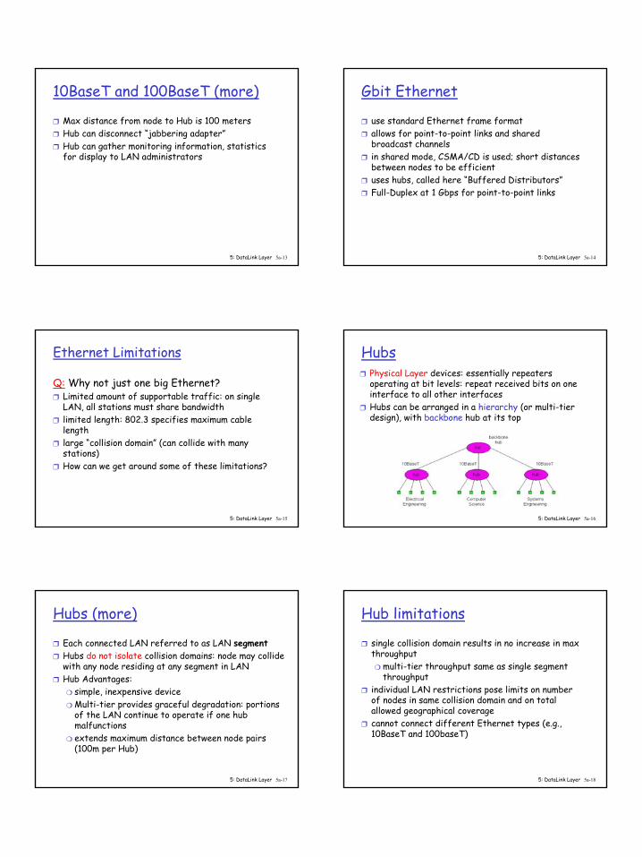
Hubs❒ Physical Layer devices: essentially repeaters
operating at bit levels: repeat received bits on one interface to all other interfaces
❒ Hubs can be arranged in a hierarchy (or multi-tier design), with backbone hub at its top
5: DataLink Layer 5a-17
Hubs (more)
❒ Each connected LAN referred to as LAN segment❒ Hubs do not isolate collision domains: node may collide
with any node residing at any segment in LAN ❒ Hub Advantages:
❍ simple, inexpensive device❍ Multi-tier provides graceful degradation: portions
of the LAN continue to operate if one hub malfunctions
❍ extends maximum distance between node pairs (100m per Hub)
5: DataLink Layer 5a-18
Hub limitations
❒ single collision domain results in no increase in max throughput❍ multi-tier throughput same as single segment
throughput❒ individual LAN restrictions pose limits on number
of nodes in same collision domain and on total allowed geographical coverage
❒ cannot connect different Ethernet types (e.g., 10BaseT and 100baseT)
4
5: DataLink Layer 5a-19
Bridges
❒ Link Layer devices: operate on Ethernet frames, examining frame header and selectively forwarding frame based on its destination
❒ Bridge isolates collision domains since it buffers frames
❒ When frame is to be forwarded on segment, bridge uses CSMA/CD to access segment and transmit
5: DataLink Layer 5a-20
Bridges (more)
❒ Bridge advantages:❍ Isolates collision domains resulting in higher
total max throughput, and does not limit the number of nodes nor geographical coverage
❍ Can connect different type Ethernet since it is a store and forward device
❍ Transparent: no need for any change to hosts LAN adapters
5: DataLink Layer 5a-21
Bridges: frame filtering, forwarding
❒ bridges filter packets ❍ same-LAN -segment frames not forwarded onto
other LAN segments ❒ forwarding:
❍ how to know which LAN segment on which to forward frame?
❍ looks like a routing problem (more shortly!)
5: DataLink Layer 5a-22
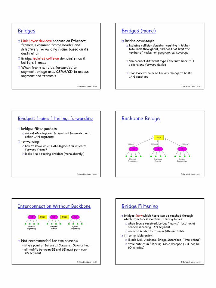
Backbone Bridge
5: DataLink Layer 5a-23
Interconnection Without Backbone
❒ Not recommended for two reasons:- single point of failure at Computer Science hub- all traffic between EE and SE must path over
CS segment
5: DataLink Layer 5a-24
Bridge Filtering
❒ bridges learn which hosts can be reached through which interfaces: maintain filtering tables❍ when frame received, bridge “learns” location of
sender: incoming LAN segment❍ records sender location in filtering table
❒ filtering table entry: ❍ (Node LAN Address, Bridge Interface, Time Stamp)❍ stale entries in Filtering Table dropped (TTL can be
60 minutes)

5
5: DataLink Layer 5a-25
Bridge Filtering
❒ filtering procedure:if destination is on LAN on which frame was received
then drop the frameelse { lookup filtering table
if entry found for destinationthen forward the frame on interface indicated;else flood; /* forward on all but the interface
on which the frame arrived*/
}
5: DataLink Layer 5a-26
Bridge Learning: exampleSuppose C sends frame to D and D replies back with
frame to C
❒ C sends frame, bridge has no info about D, so floods to both LANs
❍ bridge notes that C is on port 1 ❍ frame ignored on upper LAN ❍ frame received by D
5: DataLink Layer 5a-27
Bridge Learning: example
❒ D generates reply to C, sends ❍ bridge sees frame from D ❍ bridge notes that D is on interface 2 ❍ bridge knows C on interface 1, so selectively
forwards frame out via interface 1
5: DataLink Layer 5a-28
Bridges Spanning Tree❒ for increased reliability, desirable to have
redundant, alternate paths from source to dest❒ with multiple simultaneous paths, cycles result -
bridges may multiply and forward frame forever❒ solution: organize bridges in a spanning tree by
disabling subset of interfacesDisabled
5: DataLink Layer 5a-29
Spanning Tree Algorithm
5: DataLink Layer 5a-30
Ethernet Switches
❒ Sophisticated bridges❍ Switches usually switch in
hardware, bridges in software
❍ large number of interfaces❒ Like bridges, layer 2
(frame) forwarding, filtering using LAN addresses
❒ Can support combinations of shared/dedicated, 10/100/1000 Mbps interfaces
6
5: DataLink Layer 5a-31
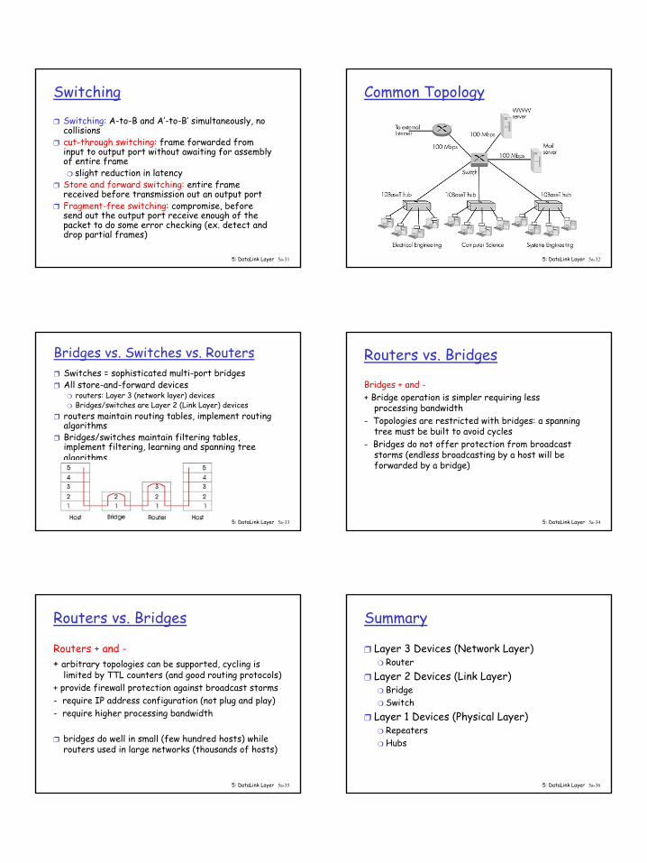
Switching
❒ Switching: A-to-B and A’-to-B’ simultaneously, no collisions
❒ cut-through switching: frame forwarded from input to output port without awaiting for assembly of entire frame❍ slight reduction in latency
❒ Store and forward switching: entire frame received before transmission out an output port
❒ Fragment-free switching: compromise, before send out the output port receive enough of the packet to do some error checking (ex. detect and drop partial frames)
5: DataLink Layer 5a-32
Common TopologyDedicated
Shared
5: DataLink Layer 5a-33
Bridges vs. Switches vs. Routers❒ Switches = sophisticated multi-port bridges❒ All store-and-forward devices
❍ routers: Layer 3 (network layer) devices ❍ Bridges/switches are Layer 2 (Link Layer) devices
❒ routers maintain routing tables, implement routing algorithms
❒ Bridges/switches maintain filtering tables, implement filtering, learning and spanning tree algorithms
5: DataLink Layer 5a-34
Routers vs. Bridges
Bridges + and -+ Bridge operation is simpler requiring less
processing bandwidth- Topologies are restricted with bridges: a spanning
tree must be built to avoid cycles - Bridges do not offer protection from broadcast
storms (endless broadcasting by a host will be forwarded by a bridge)
5: DataLink Layer 5a-35
Routers vs. Bridges
Routers + and -+ arbitrary topologies can be supported, cycling is
limited by TTL counters (and good routing protocols)+ provide firewall protection against broadcast storms- require IP address configuration (not plug and play)- require higher processing bandwidth
❒ bridges do well in small (few hundred hosts) while routers used in large networks (thousands of hosts)
5: DataLink Layer 5a-36
Summary
❒ Layer 3 Devices (Network Layer)❍ Router
❒ Layer 2 Devices (Link Layer)❍ Bridge❍ Switch
❒ Layer 1 Devices (Physical Layer)❍ Repeaters❍ Hubs
7
5: DataLink Layer 5a-37
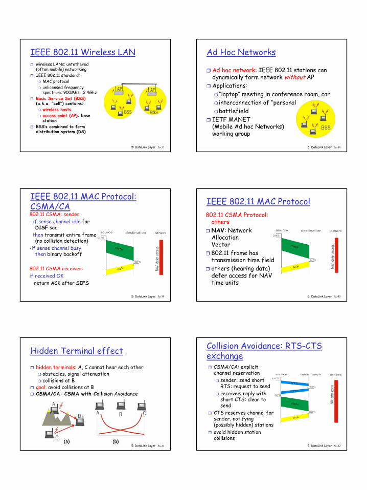
IEEE 802.11 Wireless LAN❒ wireless LANs: untethered
(often mobile) networking❒ IEEE 802.11 standard:
❍ MAC protocol❍ unlicensed frequency
spectrum: 900Mhz, 2.4Ghz❒ Basic Service Set (BSS)
(a.k.a. “cell”) contains:❍ wireless hosts❍ access point (AP): base
station❒ BSS’s combined to form
distribution system (DS)
5: DataLink Layer 5a-38
Ad Hoc Networks
❒ Ad hoc network: IEEE 802.11 stations can dynamically form network without AP
❒ Applications:❍ “laptop” meeting in conference room, car❍ interconnection of “personal” devices❍ battlefield
❒ IETF MANET (Mobile Ad hoc Networks) working group
5: DataLink Layer 5a-39
IEEE 802.11 MAC Protocol: CSMA/CA802.11 CSMA: sender- if sense channel idle for
DISF sec.then transmit entire frame (no collision detection)
-if sense channel busy then binary backoff
802.11 CSMA receiver:if received OK
return ACK after SIFS
5: DataLink Layer 5a-40
IEEE 802.11 MAC Protocol802.11 CSMA Protocol:
others❒ NAV: Network
Allocation Vector
❒ 802.11 frame has transmission time field
❒ others (hearing data) defer access for NAV time units
5: DataLink Layer 5a-41
Hidden Terminal effect
❒ hidden terminals: A, C cannot hear each other❍ obstacles, signal attenuation❍ collisions at B
❒ goal: avoid collisions at B❒ CSMA/CA: CSMA with Collision Avoidance
5: DataLink Layer 5a-42
Collision Avoidance: RTS-CTS exchange❒ CSMA/CA: explicit
channel reservation❍ sender: send short
RTS: request to send❍ receiver: reply with
short CTS: clear to send
❒ CTS reserves channel for sender, notifying (possibly hidden) stations
❒ avoid hidden station collisions
8
5: DataLink Layer 5a-43
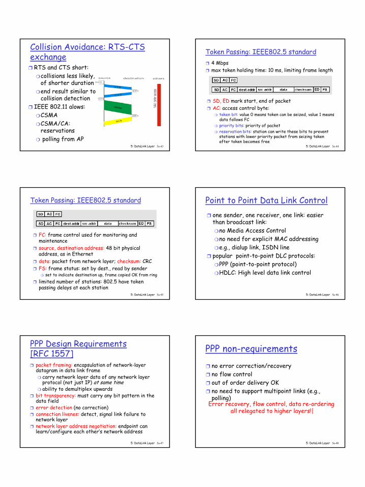
Collision Avoidance: RTS-CTS exchange
❒ RTS and CTS short:❍ collisions less likely,
of shorter duration❍ end result similar to
collision detection❒ IEEE 802.11 alows:
❍ CSMA❍ CSMA/CA:
reservations❍ polling from AP
5: DataLink Layer 5a-44
Token Passing: IEEE802.5 standard❒ 4 Mbps ❒ max token holding time: 10 ms, limiting frame length
❒ SD, ED mark start, end of packet ❒ AC: access control byte:
❍ token bit: value 0 means token can be seized, value 1 means data follows FC
❍ priority bits: priority of packet ❍ reservation bits: station can write these bits to prevent
stations with lower priority packet from seizing token after token becomes free
5: DataLink Layer 5a-45
Token Passing: IEEE802.5 standard
❒ FC: frame control used for monitoring and maintenance
❒ source, destination address: 48 bit physical address, as in Ethernet
❒ data: packet from network layer; checksum: CRC ❒ FS: frame status: set by dest., read by sender
❍ set to indicate destination up, frame copied OK from ring ❒ limited number of stations: 802.5 have token
passing delays at each station5: DataLink Layer 5a-46
Point to Point Data Link Control❒ one sender, one receiver, one link: easier
than broadcast link:❍ no Media Access Control❍ no need for explicit MAC addressing❍ e.g., dialup link, ISDN line
❒ popular point-to-point DLC protocols:❍ PPP (point-to-point protocol)❍ HDLC: High level data link control
5: DataLink Layer 5a-47
PPP Design Requirements [RFC 1557]❒ packet framing: encapsulation of network-layer
datagram in data link frame ❍ carry network layer data of any network layer
protocol (not just IP) at same time❍ ability to demultiplex upwards
❒ bit transparency: must carry any bit pattern in the data field
❒ error detection (no correction)❒ connection livenes: detect, signal link failure to
network layer❒ network layer address negotiation: endpoint can
learn/configure each other’s network address
5: DataLink Layer 5a-48
PPP non-requirements❒ no error correction/recovery❒ no flow control❒ out of order delivery OK ❒ no need to support multipoint links (e.g.,
polling)Error recovery, flow control, data re-ordering
all relegated to higher layers!|
9
5: DataLink Layer 5a-49
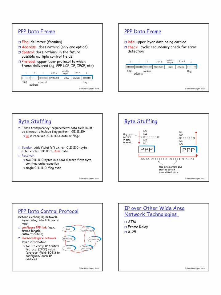
PPP Data Frame
❒ Flag: delimiter (framing)❒ Address: does nothing (only one option)❒ Control: does nothing; in the future
possible multiple control fields❒ Protocol: upper layer protocol to which
frame delivered (eg, PPP-LCP, IP, IPCP, etc)
5: DataLink Layer 5a-50
PPP Data Frame
❒ info: upper layer data being carried❒ check: cyclic redundancy check for error
detection
5: DataLink Layer 5a-51
Byte Stuffing❒ “data transparency” requirement: data field must
be allowed to include flag pattern <01111110>❍ Q: is received <01111110> data or flag?
❒ Sender: adds (“stuffs”) extra < 01111110> byte after each < 01111110> data byte
❒ Receiver:❍ two 01111110 bytes in a row: discard first byte,
continue data reception❍ single 01111110: flag byte
5: DataLink Layer 5a-52
Byte Stuffing
flag bytepatternin datato send
flag byte pattern plusstuffed byte in transmitted data
5: DataLink Layer 5a-53
PPP Data Control ProtocolBefore exchanging network-
layer data, data link peers must
❒ configure PPP link (max. frame length, authentication)
❒ learn/configure networklayer information❍ for IP: carry IP Control
Protocol (IPCP) msgs(protocol field: 8021) to configure/learn IP address
5: DataLink Layer 5a-54
IP over Other Wide Area Network Technologies❒ ATM❒ Frame Relay❒ X-25
10
5: DataLink Layer 5a-55
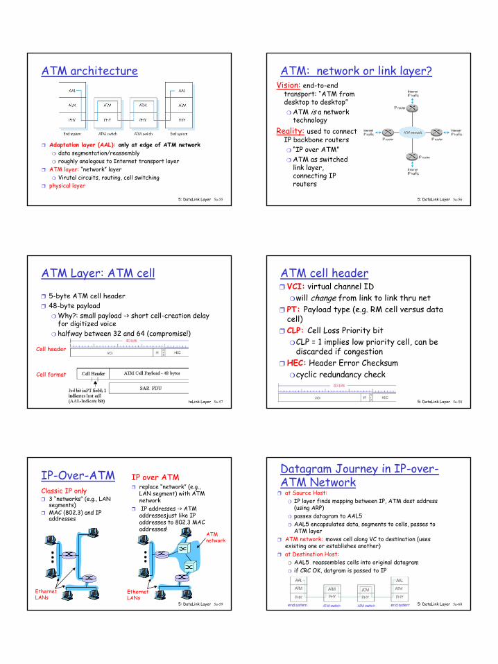
ATM architecture
❒ Adaptation layer (AAL): only at edge of ATM network❍ data segmentation/reassembly❍ roughly analogous to Internet transport layer
❒ ATM layer: “network” layer❍ Virutal circuits, routing, cell switching
❒ physical layer
5: DataLink Layer 5a-56
ATM: network or link layer?Vision: end-to-end
transport: “ATM from desktop to desktop”❍ ATM is a network
technologyReality: used to connect
IP backbone routers ❍ “IP over ATM”❍ ATM as switched
link layer, connecting IP routers
5: DataLink Layer 5a-57
ATM Layer: ATM cell
❒ 5-byte ATM cell header❒ 48-byte payload
❍ Why?: small payload -> short cell-creation delay for digitized voice
❍ halfway between 32 and 64 (compromise!)
Cell header
Cell format
5: DataLink Layer 5a-58
ATM cell header❒ VCI: virtual channel ID
❍ will change from link to link thru net❒ PT: Payload type (e.g. RM cell versus data
cell) ❒ CLP: Cell Loss Priority bit
❍ CLP = 1 implies low priority cell, can be discarded if congestion
❒ HEC: Header Error Checksum❍ cyclic redundancy check
5: DataLink Layer 5a-59
IP-Over-ATMClassic IP only❒ 3 “networks” (e.g., LAN
segments)❒ MAC (802.3) and IP
addresses
IP over ATM❒ replace “network” (e.g.,
LAN segment) with ATM network
❒ IP addresses -> ATM addressesjust like IP addresses to 802.3 MAC addresses!
ATMnetwork
EthernetLANs
EthernetLANs
5: DataLink Layer 5a-60
Datagram Journey in IP-over-ATM Network
❒ at Source Host:❍ IP layer finds mapping between IP, ATM dest address
(using ARP)❍ passes datagram to AAL5❍ AAL5 encapsulates data, segments to cells, passes to
ATM layer ❒ ATM network: moves cell along VC to destination (uses
existing one or establishes another)❒ at Destination Host:
❍ AAL5 reassembles cells into original datagram❍ if CRC OK, datgram is passed to IP
11
5: DataLink Layer 5a-61
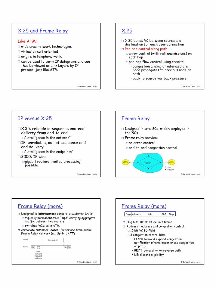
X.25 and Frame Relay
Like ATM:❒ wide area network technologies ❒ virtual circuit oriented ❒ origins in telephony world❒ can be used to carry IP datagrams and can
thus be viewed as Link Layers by IP protocol just like ATM
5: DataLink Layer 5a-62
X.25
❒ X.25 builds VC between source and destination for each user connection
❒ Per-hop control along path❍ error control (with retransmissions) on
each hop❍ per-hop flow control using credits
• congestion arising at intermediate node propagates to previous node on path
• back to source via back pressure
5: DataLink Layer 5a-63
IP versus X.25
❒ X.25: reliable in-sequence end-end delivery from end-to-end❍ “intelligence in the network”
❒ IP: unreliable, out-of-sequence end-end delivery❍ “intelligence in the endpoints”
❒ 2000: IP wins❍ gigabit routers: limited processing
possible
5: DataLink Layer 5a-64
Frame Relay
❒ Designed in late ‘80s, widely deployed in the ‘90s
❒ Frame relay service:❍ no error control❍ end-to-end congestion control
5: DataLink Layer 5a-65
Frame Relay (more)❒ Designed to interconnect corporate customer LANs
❍ typically permanent VC’s: “pipe” carrying aggregate traffic between two routers
❍ switched VC’s: as in ATM❒ corporate customer leases FR service from public
Frame Relay network (eg, Sprint, ATT)
5: DataLink Layer 5a-66
Frame Relay (more)
❒ Flag bits, 01111110, delimit frame❒ Address = address and congestion control
❍ 10 bit VC ID field❍ 3 congestion control bits
• FECN: forward explicit congestion notification (frame experienced congestion on path)
• BECN: congestion on reverse path• DE: discard eligibility
addressflags data CRC flags

12
5: DataLink Layer 5a-67
Frame Relay -VC Rate Control
❒ Committed Information Rate (CIR)❍ defined, “guaranteed” for each VC❍ negotiated at VC set up time❍ customer pays based on CIR
❒ DE bit: Discard Eligibility bit❍ Edge FR switch measures traffic rate for each
VC; marks DE bit❍ DE = 0: high priority, rate compliant frame;
deliver at “all costs”❍ DE = 1: low priority, eligible for discard when
congestion5: DataLink Layer 5a-68
LAN AddressesEach adapter on LAN has unique LAN address
5: DataLink Layer 5a-69
LAN Addresses vs IP Addresses32-bit IP address (128 bit IPv6):❒ network-layer address❒ used to get datagram to destination network
(recall IP network definition)LAN (or MAC or physical) address: ❒ used to get datagram from one interface to
another physically-connected interface (same network)
❒ 48 bit MAC address (for most LANs) burned in the adapter ROM
5: DataLink Layer 5a-70
LAN Address vs IP Addresses (more)❒ MAC address allocation administered by IEEE❒ manufacturer buys portion of MAC address space
(to assure uniqueness)❒ Analogy:
(a) MAC address: like Social Security Number(b) IP address: like postal address
❒ MAC flat address => portability ❍ can move LAN card from one LAN to another
❒ IP hierarchical address NOT portable❍ depends on network to which one attaches
5: DataLink Layer 5a-71
Recall earlier routing discussion
223.1.1.1
223.1.1.2
223.1.1.3
223.1.1.4 223.1.2.9
223.1.2.2
223.1.2.1
223.1.3.2223.1.3.1
223.1.3.27
A
BE
Starting at A, given IP datagram addressed to B:
❒ look up net. address of B, find B on same net. as A
❒ link layer send datagram to B inside link-layer frame
B’s MACaddr
A’s MACaddr
A’s IPaddr
B’s IPaddr IP payload
datagramframe
frame source,dest address
datagram source,dest address
5: DataLink Layer 5a-72
Question: How can we determine the MAC address of Bgiven B’s IP address?
13
5: DataLink Layer 5a-73
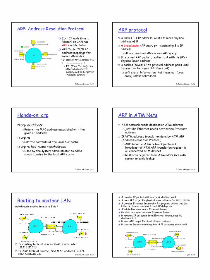
ARP: Address Resolution Protocol
❒ Each IP node (Host, Router) on LAN has ARP module, table
❒ ARP Table: IP/MAC address mappings for some LAN nodes
< IP address; MAC address; TTL>< ………………………….. >
❍ TTL (Time To Live): time after which address mapping will be forgotten (typically 20 min)
5: DataLink Layer 5a-74
ARP protocol❒ A knows B's IP address, wants to learn physical
address of B ❒ A broadcasts ARP query pkt, containing B's IP
address ❍ all machines on LAN receive ARP query
❒ B receives ARP packet, replies to A with its (B's) physical layer address
❒ A caches (saves) IP-to-physical address pairs until information becomes old (times out) ❍ soft state: information that times out (goes
away) unless refreshed
5: DataLink Layer 5a-75
Hands-on: arp
❒ arp ipaddress❍ Return the MAC address associated with the
given IP address❒ arp –a
❍ List the contents of the local ARP cache❒ arp –s hostname macAddress
❍ Used by the system administrator to add a specific entry to the local ARP cache
5: DataLink Layer 5a-76
ARP in ATM Nets
❒ ATM network needs destination ATM address❍ just like Ethernet needs destination Ethernet
address❒ IP/ATM address translation done by ATM ARP
(Address Resolution Protocol)❍ ARP server in ATM network performs
broadcast of ATM ARP translation request to all connected ATM devices
❍ hosts can register their ATM addresses with server to avoid lookup
5: DataLink Layer 5a-77
Routing to another LANwalkthrough: routing from A to B via R
❒ In routing table at source Host, find router 111.111.111.110
❒ In ARP table at source, find MAC address E6-E9-00-17-BB-4B, etc
A
RB
5: DataLink Layer 5a-78
❒ A creates IP packet with source A, destination B ❒ A uses ARP to get R’s physical layer address for 111.111.111.110❒ A creates Ethernet frame with R's physical address as dest,
Ethernet frame contains A-to-B IP datagram❒ A’s data link layer sends Ethernet frame ❒ R’s data link layer receives Ethernet frame ❒ R removes IP datagram from Ethernet frame, sees its
destined to B❒ R uses ARP to get B’s physical layer address ❒ R creates frame containing A-to-B IP datagram sends to B
A
RB
14
5: DataLink Layer 5a-79
Summary
❒ principles behind data link layer services:❍ error detection, correction❍ sharing a broadcast channel: multiple access❍ link layer addressing, ARP
❒ various link layer technologies❍ Ethernethubs, bridges, switches❍ IEEE 802.11 LANs❍ PPP❍ ATM, X.25, Frame Relay
❒ journey down the protocol stack now OVER!❍ Next stops: security, network management(?)


