Link Layer and LANs - Simon Fraser Universityljilja/ENSC835/Spring09/News/Kuros… · ·...
108
5: DataLink Layer 5-1 Chapter 5 Link Layer and LANs A note on the use of these ppt slides: We’re making these slides freely available to all (faculty, students, readers). They’re in PowerPoint form so you can add, modify, and delete slides (including this one) and slide content to suit your needs. They obviously represent a lot of work on our part. In return for use, we only ask the following: If you use these slides (e.g., in a class) in substantially unaltered form, that you mention their source (after all, we’d like people to use our book!) If you post any slides in substantially unaltered form on a www site, that you note that they are adapted from (or perhaps identical to) our slides, and note our copyright of this material. Thanks and enjoy! JFK/KWR All material copyright 1996-2007 J.F Kurose and K.W. Ross, All Rights Reserved Computer Networking: A Top Down Approach 4 th edition. Jim Kurose, Keith Ross Addison-Wesley, July 2007.
Transcript of Link Layer and LANs - Simon Fraser Universityljilja/ENSC835/Spring09/News/Kuros… · ·...

5 DataLink Layer 5-1
Chapter 5Link Layer and LANs
A note on the use of these ppt slidesWersquore making these slides freely available to all (faculty students readers) Theyrsquore in PowerPoint form so you can add modify and delete slides (including this one) and slide content to suit your needs They obviously represent a lot of work on our part In return for use we only ask the following If you use these slides (eg in a class) in substantially unaltered form that you mention their source (after all wersquod like people to use our book) If you post any slides in substantially unaltered form on a www site that you note that they are adapted from (or perhaps identical to) our slides and note our copyright of this material
Thanks and enjoy JFKKWR
All material copyright 1996-2007JF Kurose and KW Ross All Rights Reserved
Computer Networking A Top Down Approach 4th edition Jim Kurose Keith RossAddison-Wesley July 2007
5 DataLink Layer 5-2
Chapter 5 The Data Link LayerOur goals understand principles behind data link layer
services error detection correction sharing a broadcast channel multiple access link layer addressing reliable data transfer flow control done
instantiation and implementation of various link layer technologies
5 DataLink Layer 5-3
Link Layer
51 Introduction and services
52 Error detection and correction
53Multiple access protocols
54 Link-layer Addressing
55 Ethernet
56 Link-layer switches 57 PPP 58 Link virtualization
ATM MPLS
5 DataLink Layer 5-4
Link Layer IntroductionSome terminology hosts and routers are nodes communication channels that
connect adjacent nodes along communication path are links
wired links wireless links LANs
layer-2 packet is a frameencapsulates datagram
data-link layer has responsibility of transferring datagram from one node to adjacent node over a link
5 DataLink Layer 5-5
Link layer context datagram transferred by
different link protocols over different links
eg Ethernet on first link frame relay on intermediate links 80211 on last link
each link protocol provides different services
eg may or may not provide rdt over link
transportation analogy trip from Princeton to
Lausanne limo Princeton to JFK plane JFK to Geneva train Geneva to Lausanne
tourist = datagram transport segment =
communication link transportation mode =
link layer protocol travel agent = routing
algorithm
5 DataLink Layer 5-6
Link Layer Services framing link access
encapsulate datagram into frame adding header trailer channel access if shared medium ldquoMACrdquo addresses used in frame headers to identify
source dest bull different from IP address
reliable delivery between adjacent nodes we learned how to do this already (chapter 3) seldom used on low bit-error link (fiber some twisted
pair) wireless links high error rates
bull Q why both link-level and end-end reliability
5 DataLink Layer 5-7
Link Layer Services (more)
flow control pacing between adjacent sending and receiving nodes
error detection errors caused by signal attenuation noise receiver detects presence of errors
bull signals sender for retransmission or drops frame
error correction receiver identifies and corrects bit error(s) without
resorting to retransmission half-duplex and full-duplex
with half duplex nodes at both ends of link can transmit but not at same time
5 DataLink Layer 5-8
Where is the link layer implemented
in each and every host link layer implemented in
ldquoadaptorrdquo (aka network interface card NIC)
Ethernet card PCMCI card 80211 card
implements link physical layer
attaches into hostrsquos system buses
combination of hardware software firmware
controller
physicaltransmission
cpu memory
host bus (eg PCI)
network adaptercard
host schematic
applicationtransportnetwork
link
linkphysical
5 DataLink Layer 5-9
Adaptors Communicating
sending side encapsulates datagram in
frame adds error checking bits
rdt flow control etc
receiving side looks for errors rdt flow
control etc extracts datagram passes
to upper layer at receiving side
controller controller
sending host receiving host
datagram datagram
datagram
frame
5 DataLink Layer 5-10
Link Layer
51 Introduction and services
52 Error detection and correction
53Multiple access protocols
54 Link-layer Addressing
55 Ethernet
56 Link-layer switches 57 PPP 58 Link Virtualization
ATM MPLS
5 DataLink Layer 5-11
Error DetectionEDC= Error Detection and Correction bits (redundancy)D = Data protected by error checking may include header fields
bull Error detection not 100 reliablebull protocol may miss some errors but rarelybull larger EDC field yields better detection and correction
otherwise
5 DataLink Layer 5-12
Parity CheckingSingle Bit ParityDetect single bit errors
Two Dimensional Bit ParityDetect and correct single bit errors
0 0
5 DataLink Layer 5-13
Internet checksum (review)
Sender treat segment contents
as sequence of 16-bit integers
checksum addition (1rsquos complement sum) of segment contents
sender puts checksum value into UDP checksum field
Receiver compute checksum of
received segment check if computed checksum
equals checksum field value NO - error detected YES - no error detected
But maybe errors nonetheless
Goal detect ldquoerrorsrdquo (eg flipped bits) in transmitted packet (note used at transport layer only)
5 DataLink Layer 5-14
Checksumming Cyclic Redundancy Check view data bits D as a binary number choose r+1 bit pattern (generator) G goal choose r CRC bits R such that
ltDRgt exactly divisible by G (modulo 2) receiver knows G divides ltDRgt by G If non-zero remainder
error detected can detect all burst errors less than r+1 bits
widely used in practice (80211 WiFi ATM)
5 DataLink Layer 5-15
CRC ExampleWant
D2r XOR R = nGequivalently
D2r = nG XOR R equivalently
if we divide D2r by G want remainder R
R = remainder[ ]D2r
G
5 DataLink Layer 5-16
Link Layer
51 Introduction and services
52 Error detection and correction
53Multiple access protocols
54 Link-layer Addressing
55 Ethernet
56 Link-layer switches 57 PPP 58 Link Virtualization
ATM MPLS
5 DataLink Layer 5-17
Multiple Access Links and ProtocolsTwo types of ldquolinksrdquo point-to-point
PPP for dial-up access point-to-point link between Ethernet switch and host
broadcast (shared wire or medium) old-fashioned Ethernet upstream HFC 80211 wireless LAN
shared wire (eg cabled Ethernet)
shared RF(eg 80211 WiFi)
shared RF(satellite)
humans at acocktail party
(shared air acoustical)
5 DataLink Layer 5-18
Multiple Access protocols single shared broadcast channel two or more simultaneous transmissions by nodes
interference collision if node receives two or more signals at the same time
multiple access protocol distributed algorithm that determines how nodes
share channel ie determine when node can transmit communication about channel sharing must use channel
itself no out-of-band channel for coordination
5 DataLink Layer 5-19
Ideal Multiple Access Protocol
Broadcast channel of rate R bps1 when one node wants to transmit it can send at
rate R2 when M nodes want to transmit each can send at
average rate RM3 fully decentralized
no special node to coordinate transmissions no synchronization of clocks slots
4 simple
5 DataLink Layer 5-20
MAC Protocols a taxonomyThree broad classes Channel Partitioning
divide channel into smaller ldquopiecesrdquo (time slots frequency code)
allocate piece to node for exclusive use Random Access
channel not divided allow collisions ldquorecoverrdquo from collisions
ldquoTaking turnsrdquo nodes take turns but nodes with more to send can take
longer turns
5 DataLink Layer 5-21
Channel Partitioning MAC protocols TDMA
TDMA time division multiple access access to channel in rounds each station gets fixed length slot (length = pkt
trans time) in each round unused slots go idle example 6-station LAN 134 have pkt slots 256
idle
1 3 4 1 3 4
6-slotframe
5 DataLink Layer 5-22
Channel Partitioning MAC protocols FDMA
FDMA frequency division multiple access channel spectrum divided into frequency bands each station assigned fixed frequency band unused transmission time in frequency bands go idle example 6-station LAN 134 have pkt frequency
bands 256 idle
freq
uenc
y ba
nds
time
FDM cable
5 DataLink Layer 5-23
Random Access Protocols
When node has packet to send transmit at full channel data rate R no a priori coordination among nodes
two or more transmitting nodes ldquocollisionrdquo random access MAC protocol specifies
how to detect collisions how to recover from collisions (eg via delayed
retransmissions) Examples of random access MAC protocols
slotted ALOHA ALOHA CSMA CSMACD CSMACA
5 DataLink Layer 5-24
Slotted ALOHA
Assumptions all frames same size time divided into equal
size slots (time to transmit 1 frame)
nodes start to transmit only slot beginning
nodes are synchronized if 2 or more nodes
transmit in slot all nodes detect collision
Operation when node obtains fresh
frame transmits in next slot if no collision node can
send new frame in next slot
if collision node retransmits frame in each subsequent slot with prob p until success
5 DataLink Layer 5-25
Slotted ALOHA
Pros single active node can
continuously transmit at full rate of channel
highly decentralized only slots in nodes need to be in sync
simple
Cons collisions wasting slots idle slots nodes may be able to
detect collision in less than time to transmit packet
clock synchronization
5 DataLink Layer 5-26
Slotted Aloha efficiency
suppose N nodes with many frames to send each transmits in slot with probability p
prob that given node has success in a slot = p(1-p)N-1
prob that any node has a success = Np(1-p)N-1
max efficiency find p that maximizes Np(1-p)N-1
for many nodes take limit of Np(1-p)N-1
as N goes to infinity gives
Max efficiency = 1e = 37
Efficiency long-run fraction of successful slots (many nodes all with many frames to send)
At best channelused for useful transmissions 37of time
5 DataLink Layer 5-27
Pure (unslotted) ALOHA unslotted Aloha simpler no synchronization when frame first arrives
transmit immediately collision probability increases
frame sent at t0 collides with other frames sent in [t0-1t0+1]
5 DataLink Layer 5-28
Pure Aloha efficiencyP(success by given node) = P(node transmits)
P(no other node transmits in [p0-1p0] P(no other node transmits in [p0-1p0]
= p (1-p)N-1 (1-p)N-1
= p (1-p)2(N-1)
hellip choosing optimum p and then letting n -gt infty
= 1(2e) = 18
even worse than slotted Aloha
5 DataLink Layer 5-29
CSMA (Carrier Sense Multiple Access)
CSMA listen before transmitIf channel sensed idle transmit entire frame If channel sensed busy defer transmission
human analogy donrsquot interrupt others
5 DataLink Layer 5-30
CSMA collisionscollisions can still occurpropagation delay means two nodes may not heareach otherrsquos transmission
collisionentire packet transmission time wasted
spatial layout of nodes
noterole of distance amp propagation delay in determining collision probability
5 DataLink Layer 5-31
CSMACD (Collision Detection)CSMACD carrier sensing deferral as in CSMA
collisions detected within short time colliding transmissions aborted reducing channel
wastage collision detection
easy in wired LANs measure signal strengths compare transmitted received signals
difficult in wireless LANs received signal strength overwhelmed by local transmission strength
human analogy the polite conversationalist
5 DataLink Layer 5-32
CSMACD collision detection
5 DataLink Layer 5-33
ldquoTaking Turnsrdquo MAC protocols
channel partitioning MAC protocols share channel efficiently and fairly at high load inefficient at low load delay in channel access
1N bandwidth allocated even if only 1 active node
Random access MAC protocols efficient at low load single node can fully
utilize channel high load collision overhead
ldquotaking turnsrdquo protocolslook for best of both worlds
5 DataLink Layer 5-34
ldquoTaking Turnsrdquo MAC protocolsPolling master node
ldquoinvitesrdquo slave nodes to transmit in turn
typically used with ldquodumbrdquo slave devices
concerns polling overhead latency single point of
failure (master)
master
slaves
poll
data
data
5 DataLink Layer 5-35
ldquoTaking Turnsrdquo MAC protocolsToken passing control token passed
from one node to next sequentially
token message concerns
token overhead latency single point of failure
(token)
T
data
(nothingto send)
T
5 DataLink Layer 5-36
Summary of MAC protocols
channel partitioning by time frequency or code Time Division Frequency Division
random access (dynamic) ALOHA S-ALOHA CSMA CSMACD carrier sensing easy in some technologies (wire) hard in
others (wireless) CSMACD used in Ethernet CSMACA used in 80211
taking turns polling from central site token passing Bluetooth FDDI IBM Token Ring
5 DataLink Layer 5-37
LAN technologiesData link layer so far
services error detectioncorrection multiple access
Next LAN technologies addressing Ethernet switches PPP
5 DataLink Layer 5-38
Link Layer
51 Introduction and services
52 Error detection and correction
53Multiple access protocols
54 Link-Layer Addressing
55 Ethernet
56 Link-layer switches 57 PPP 58 Link Virtualization
ATM MPLS
5 DataLink Layer 5-39
MAC Addresses and ARP
32-bit IP address network-layer address used to get datagram to destination IP subnet
MAC (or LAN or physical or Ethernet) address function get frame from one interface to another
physically-connected interface (same network) 48 bit MAC address (for most LANs)
bull burned in NIC ROM also sometimes software settable
5 DataLink Layer 5-40
LAN Addresses and ARPEach adapter on LAN has unique LAN address
Broadcast address =FF-FF-FF-FF-FF-FF
= adapter
1A-2F-BB-76-09-AD
58-23-D7-FA-20-B0
0C-C4-11-6F-E3-98
71-65-F7-2B-08-53
LAN(wired orwireless)
5 DataLink Layer 5-41
LAN Address (more)
MAC address allocation administered by IEEE manufacturer buys portion of MAC address space
(to assure uniqueness) analogy
(a) MAC address like Social Security Number(b) IP address like postal address
MAC flat address portability can move LAN card from one LAN to another
IP hierarchical address NOT portable address depends on IP subnet to which node is attached
5 DataLink Layer 5-42
ARP Address Resolution Protocol
Each IP node (host router) on LAN has ARP table
ARP table IPMAC address mappings for some LAN nodes
lt IP address MAC address TTLgt TTL (Time To Live) time
after which address mapping will be forgotten (typically 20 min)
Question how to determineMAC address of Bknowing Brsquos IP address
1A-2F-BB-76-09-AD
58-23-D7-FA-20-B0
0C-C4-11-6F-E3-98
71-65-F7-2B-08-53
LAN
137196723
137196778
137196714
137196788
5 DataLink Layer 5-43
ARP protocol Same LAN (network)
A wants to send datagram to B and Brsquos MAC address not in Arsquos ARP table
A broadcasts ARP query packet containing Bs IP address
dest MAC address = FF-FF-FF-FF-FF-FF
all machines on LAN receive ARP query
B receives ARP packet replies to A with its (Bs) MAC address
frame sent to Arsquos MAC address (unicast)
A caches (saves) IP-to-MAC address pair in its ARP table until information becomes old (times out)
soft state information that times out (goes away) unless refreshed
ARP is ldquoplug-and-playrdquo nodes create their ARP
tables without intervention from net administrator
5 DataLink Layer 5-44
DHCP Dynamic Host Configuration Protocol
Goal allow host to dynamically obtain its IP address from network server when joining network support for mobile users joining network host holds address only while connected and ldquoonrdquo
(allowing address reuse) renew address already in use
DHCP overview 1 host broadcasts ldquoDHCP discoverrdquo msg 2 DHCP server responds with ldquoDHCP offerrdquo msg 3 host requests IP address ldquoDHCP requestrdquo msg 4 DHCP server sends address ldquoDHCP ackrdquo msg
5 DataLink Layer 5-45
DHCP client-server scenario
223111
223112
223113
223114 223129
223122
223121
223132223131
2231327
A
BE
DHCP server
arriving DHCP client needsaddress in this(2231224) network
5 DataLink Layer 5-46
DHCP client-server scenarioDHCP server 223125 arriving
client
time
DHCP discover
src 0000 68 dest 25525525525567yiaddr 0000transaction ID 654
DHCP offersrc 223125 67 dest 255255255255 68yiaddrr 223124transaction ID 654Lifetime 3600 secs
DHCP request
src 0000 68 dest 255255255255 67yiaddrr 223124transaction ID 655Lifetime 3600 secs
DHCP ACKsrc 223125 67 dest 255255255255 68yiaddrr 223124transaction ID 655Lifetime 3600 secs
5 DataLink Layer 5-47
Addressing routing to another LAN
R
1A-23-F9-CD-06-9B
222222222220111111111110
E6-E9-00-17-BB-4B
CC-49-DE-D0-AB-7D
111111111112
111111111111
A74-29-9C-E8-FF-55
222222222221
88-B2-2F-54-1A-0F
B222222222222
49-BD-D2-C7-56-2A
walkthrough send datagram from A to B via Rassume A knows Brsquos IP address
two ARP tables in router R one for each IP network (LAN)
5 DataLink Layer 5-48
A creates IP datagram with source A destination B A uses ARP to get Rrsquos MAC address for 111111111110 A creates link-layer frame with Rs MAC address as dest
frame contains A-to-B IP datagram Arsquos NIC sends frame Rrsquos NIC receives frame R removes IP datagram from Ethernet frame sees its
destined to B R uses ARP to get Brsquos MAC address R creates frame containing A-to-B IP datagram sends to B
R
1A-23-F9-CD-06-9B
222222222220111111111110
E6-E9-00-17-BB-4B
CC-49-DE-D0-AB-7D
111111111112
111111111111
A74-29-9C-E8-FF-55
222222222221
88-B2-2F-54-1A-0F
B222222222222
49-BD-D2-C7-56-2A
This is a really importantexample ndash make sure youunderstand
5 DataLink Layer 5-49
Link Layer
51 Introduction and services
52 Error detection and correction
53Multiple access protocols
54 Link-Layer Addressing
55 Ethernet
56 Link-layer switches 57 PPP 58 Link Virtualization
ATM and MPLS
5 DataLink Layer 5-50
Ethernetldquodominantrdquo wired LAN technology cheap $20 for NIC first widely used LAN technology simpler cheaper than token LANs and ATM kept up with speed race 10 Mbps ndash 10 Gbps
Metcalfersquos Ethernetsketch
5 DataLink Layer 5-51
Star topology bus topology popular through mid 90s
all nodes in same collision domain (can collide with each other)
today star topology prevails active switch in center each ldquospokerdquo runs a (separate) Ethernet protocol (nodes
do not collide with each other)
switch
bus coaxial cable star
5 DataLink Layer 5-52
Ethernet Frame StructureSending adapter encapsulates IP datagram (or other
network layer protocol packet) in Ethernet frame
Preamble 7 bytes with pattern 10101010 followed by one
byte with pattern 10101011 used to synchronize receiver sender clock rates
5 DataLink Layer 5-53
Ethernet Frame Structure (more) Addresses 6 bytes
if adapter receives frame with matching destination address or with broadcast address (eg ARP packet) it passes data in frame to network layer protocol
otherwise adapter discards frame Type indicates higher layer protocol (mostly IP
but others possible eg Novell IPX AppleTalk) CRC checked at receiver if error is detected
frame is dropped
5 DataLink Layer 5-54
Ethernet Unreliable connectionless
connectionless No handshaking between sending and receiving NICs
unreliable receiving NIC doesnrsquot send acks or nacksto sending NIC
stream of datagrams passed to network layer can have gaps (missing datagrams)
gaps will be filled if app is using TCP otherwise app will see gaps
Ethernetrsquos MAC protocol unslotted CSMACD
5 DataLink Layer 5-55
Ethernet CSMACD algorithm1 NIC receives datagram
from network layer creates frame
2 If NIC senses channel idle starts frame transmission If NIC senses channel busy waits until channel idle then transmits
3 If NIC transmits entire frame without detecting another transmission NIC is done with frame
4 If NIC detects another transmission while transmitting aborts and sends jam signal
5 After aborting NIC enters exponential backoff after mthcollision NIC chooses K at random from 012hellip2m-1 NIC waits K512 bit times returns to Step 2
5 DataLink Layer 5-56
Ethernetrsquos CSMACD (more)Jam Signal make sure all
other transmitters are aware of collision 48 bits
Bit time 1 microsec for 10 Mbps Ethernet for K=1023 wait time is about 50 msec
Exponential Backoff Goal adapt retransmission
attempts to estimated current load
heavy load random wait will be longer
first collision choose K from 01 delay is K 512 bit transmission times
after second collision choose K from 0123hellip
after ten collisions choose K from 01234hellip1023
Seeinteract with Javaapplet on AWL Web sitehighly recommended
5 DataLink Layer 5-57
CSMACD efficiency
Tprop = max prop delay between 2 nodes in LAN ttrans = time to transmit max-size frame
efficiency goes to 1 as tprop goes to 0 as ttrans goes to infinity
better performance than ALOHA and simple cheap decentralized
transprop ttefficiency
511
+=
5 DataLink Layer 5-58
8023 Ethernet Standards Link amp Physical Layers
many different Ethernet standards common MAC protocol and frame format different speeds 2 Mbps 10 Mbps 100 Mbps
1Gbps 10G bps different physical layer media fiber cable
applicationtransportnetwork
linkphysical
MAC protocoland frame format
100BASE-TX
100BASE-T4
100BASE-FX100BASE-T2
100BASE-SX 100BASE-BX
fiber physical layercopper (twisterpair) physical layer
5 DataLink Layer 5-59
Manchester encoding
used in 10BaseT each bit has a transition allows clocks in sending and receiving nodes to
synchronize to each other no need for a centralized global clock among nodes
Hey this is physical-layer stuff
5 DataLink Layer 5-60
Link Layer
51 Introduction and services
52 Error detection and correction
53 Multiple access protocols
54 Link-layer Addressing
55 Ethernet
56 Link-layer switches 57 PPP 58 Link Virtualization
ATM MPLS
5 DataLink Layer 5-61
Hubshellip physical-layer (ldquodumbrdquo) repeaters
bits coming in one link go out all other links at same rate
all nodes connected to hub can collide with one another
no frame buffering no CSMACD at hub host NICs detect
collisions
twisted pair
hub
5 DataLink Layer 5-62
Switch link-layer device smarter than hubs take
active role store forward Ethernet frames examine incoming framersquos MAC address
selectively forward frame to one-or-more outgoing links when frame is to be forwarded on segment uses CSMACD to access segment
transparent hosts are unaware of presence of switches
plug-and-play self-learning switches do not need to be configured
5 DataLink Layer 5-63
Switch allows multiple simultaneous transmissions
hosts have dedicated direct connection to switch
switches buffer packets Ethernet protocol used on
each incoming link but no collisions full duplex
each link is its own collision domain
switching A-to-Arsquo and B-to-Brsquo simultaneously without collisions
not possible with dumb hub
A
Arsquo
B
Brsquo
C
Crsquo
switch with six interfaces(123456)
1 2 345
6
5 DataLink Layer 5-64
Switch Table
Q how does switch know that Arsquo reachable via interface 4 Brsquo reachable via interface 5
A each switch has a switch table each entry
(MAC address of host interface to reach host time stamp)
looks like a routing table Q how are entries created
maintained in switch table something like a routing
protocol
A
Arsquo
B
Brsquo
C
Crsquo
switch with six interfaces(123456)
1 2 345
6
5 DataLink Layer 5-65
Switch self-learning
switch learns which hosts can be reached through which interfaces
when frame received switch ldquolearnsrdquo location of sender incoming LAN segment
records senderlocation pair in switch table
A
Arsquo
B
Brsquo
C
Crsquo
1 2 345
6
A Arsquo
Source ADest Arsquo
MAC addr interface TTLSwitch table
(initially empty)A 1 60
5 DataLink Layer 5-66
Switch frame filteringforwardingWhen frame received
1 record link associated with sending host2 index switch table using MAC dest address3 if entry found for destination
then if dest on segment from which frame arrived
then drop the frameelse forward the frame on interface indicated
else flood forward on all but the interface
on which the frame arrived
5 DataLink Layer 5-67
Self-learning forwarding example
A
Arsquo
B
Brsquo
C
Crsquo
1 2 345
6
A Arsquo
Source ADest Arsquo
MAC addr interface TTLSwitch table
(initially empty)A 1 60
A ArsquoA ArsquoA ArsquoA ArsquoA Arsquo frame destination
unknown flood
Arsquo A
destination A location known
Arsquo 4 60
selective send
5 DataLink Layer 5-68
Interconnecting switches
switches can be connected together
A
B
Q sending from A to F - how does S1 know to forward frame destined to F via S4 and S3
A self learning (works exactly the same as in single-switch case)
S1
C D
E
FS2
S4
S3
HI
G
5 DataLink Layer 5-69
Self-learning multi-switch exampleSuppose C sends frame to I I responds to C
Q show switch tables and packet forwarding in S1 S2 S3 S4
A
B
S1
C D
E
FS2
S4
S3
HI
G
12
5 DataLink Layer 5-70
Institutional network
to externalnetwork
router
IP subnet
mail server
web server
5 DataLink Layer 5-71
Switches vs Routers both store-and-forward devices
routers network layer devices (examine network layer headers)
switches are link layer devices routers maintain routing tables implement routing
algorithms switches maintain switch tables implement
filtering learning algorithms
5 DataLink Layer 5-72
Summary comparison
hubs routers switches
traffic isolation
no yes yes
plug amp play yes no yes
optimal routing
no yes no
cut through
yes no yes
5 DataLink Layer 5-73
Link Layer
51 Introduction and services
52 Error detection and correction
53Multiple access protocols
54 Link-Layer Addressing
55 Ethernet
56 Hubs and switches 57 PPP 58 Link Virtualization
ATM
5 DataLink Layer 5-74
Point to Point Data Link Control one sender one receiver one link easier than
broadcast link no Media Access Control no need for explicit MAC addressing eg dialup link ISDN line
popular point-to-point DLC protocols PPP (point-to-point protocol) HDLC High level data link control (Data link
used to be considered ldquohigh layerrdquo in protocol stack
5 DataLink Layer 5-75
PPP Design Requirements [RFC 1557]
packet framing encapsulation of network-layer datagram in data link frame carry network layer data of any network layer
protocol (not just IP) at same time ability to demultiplex upwards
bit transparency must carry any bit pattern in the data field
error detection (no correction) connection liveness detect signal link failure to
network layer network layer address negotiation endpoint can
learnconfigure each otherrsquos network address
5 DataLink Layer 5-76
PPP non-requirements
no error correctionrecovery no flow control out of order delivery OK no need to support multipoint links (eg polling)
Error recovery flow control data re-ordering all relegated to higher layers
5 DataLink Layer 5-77
PPP Data Frame
Flag delimiter (framing) Address does nothing (only one option) Control does nothing in the future possible
multiple control fields Protocol upper layer protocol to which frame
delivered (eg PPP-LCP IP IPCP etc)
5 DataLink Layer 5-78
PPP Data Frame
info upper layer data being carried check cyclic redundancy check for error
detection
5 DataLink Layer 5-79
Byte Stuffing ldquodata transparencyrdquo requirement data field must
be allowed to include flag pattern lt01111110gt Q is received lt01111110gt data or flag
Sender adds (ldquostuffsrdquo) extra lt 01111110gt byte after each lt 01111110gt data byte
Receiver two 01111110 bytes in a row discard first byte
continue data reception single 01111110 flag byte
5 DataLink Layer 5-80
Byte Stuffing
flag bytepatternin datato send
flag byte pattern plusstuffed byte in transmitted data
5 DataLink Layer 5-81
PPP Data Control ProtocolBefore exchanging network-
layer data data link peers must
configure PPP link (max frame length authentication)
learnconfigure networklayer information for IP carry IP Control
Protocol (IPCP) msgs (protocol field 8021) to configurelearn IP address
5 DataLink Layer 5-82
Link Layer
51 Introduction and services
52 Error detection and correction
53Multiple access protocols
54 Link-Layer Addressing
55 Ethernet
56 Hubs and switches 57 PPP 58 Link Virtualization
ATM and MPLS
5 DataLink Layer 5-83
Virtualization of networks
Virtualization of resources powerful abstraction in systems engineering
computing examples virtual memory virtual devices Virtual machines eg java IBM VM os from 1960rsquos70rsquos
layering of abstractions donrsquot sweat the details of the lower layer only deal with lower layers abstractly
5 DataLink Layer 5-84
The Internet virtualizing networks
1974 multiple unconnected nets
ARPAnet data-over-cable networks packet satellite network (Aloha) packet radio network
hellip differing in addressing conventions packet formats error recovery routing
ARPAnet satellite netA Protocol for Packet Network Intercommunication V Cerf R Kahn IEEE Transactions on CommunicationsMay 1974 pp 637-648
5 DataLink Layer 5-85
The Internet virtualizing networks
ARPAnet satellite net
gateway
Internetwork layer (IP) addressing internetwork
appears as single uniform entity despite underlying local network heterogeneity
network of networks
Gateway ldquoembed internetwork packets in
local packet format or extract themrdquo
route (at internetwork level) to next gateway
5 DataLink Layer 5-86
Cerf amp Kahnrsquos Internetwork Architecture
What is virtualized two layers of addressing internetwork and local
network new layer (IP) makes everything homogeneous at
internetwork layer underlying local network technology
cable satellite 56K telephone modem today ATM MPLS
hellip ldquoinvisiblerdquo at internetwork layer Looks like a link layer technology to IP
5 DataLink Layer 5-87
ATM and MPLS
ATM MPLS separate networks in their own right different service models addressing routing
from Internet viewed by Internet as logical link connecting
IP routers just like dialup link is really part of separate
network (telephone network) ATM MPLS of technical interest in their
own right
5 DataLink Layer 5-88
Asynchronous Transfer Mode ATM 1990rsquos00 standard for high-speed (155Mbps to
622 Mbps and higher) Broadband Integrated Service Digital Network architecture
Goal integrated end-end transport of carry voice video data meeting timingQoS requirements of voice video
(versus Internet best-effort model) ldquonext generationrdquo telephony technical roots in
telephone world packet-switching (fixed length packets called
ldquocellsrdquo) using virtual circuits
5 DataLink Layer 5-89
ATM architecture
adaptation layer only at edge of ATM network data segmentationreassembly roughly analagous to Internet transport layer
ATM layer ldquonetworkrdquo layer cell switching routing
physical layer
physical
ATM
AAL
physical
ATM
AAL
physical
ATM
physical
ATM
end system end systemswitch switch
5 DataLink Layer 5-90
ATM network or link layerVision end-to-end
transport ldquoATM from desktop to desktoprdquo ATM is a network
technologyReality used to connect
IP backbone routers ldquoIP over ATMrdquo ATM as switched
link layer connecting IP routers
ATMnetwork
IPnetwork
5 DataLink Layer 5-91
ATM Adaptation Layer (AAL)
ATM Adaptation Layer (AAL) ldquoadaptsrdquo upper layers (IP or native ATM applications) to ATM layer below
AAL present only in end systems not in switches AAL layer segment (headertrailer fields data)
fragmented across multiple ATM cells analogy TCP segment in many IP packets
physical
ATM
AAL
physical
ATM
AAL
physical
ATM
physical
ATM
end system end systemswitch switch
5 DataLink Layer 5-92
ATM Adaptation Layer (AAL) [more]
Different versions of AAL layers depending on ATM service class
AAL1 for CBR (Constant Bit Rate) services eg circuit emulation AAL2 for VBR (Variable Bit Rate) services eg MPEG video AAL5 for data (eg IP datagrams)
AAL PDU
ATM cell
User data
5 DataLink Layer 5-93
ATM LayerService transport cells across ATM network analogous to IP network layer very different services than IP network layer
NetworkArchitecture
Internet
ATM
ATM
ATM
ATM
ServiceModel
best effort
CBR
VBR
ABR
UBR
Bandwidth
none
constantrateguaranteedrateguaranteed minimumnone
Loss
no
yes
yes
no
no
Order
no
yes
yes
yes
yes
Timing
no
yes
yes
no
no
Congestionfeedback
no (inferredvia loss)nocongestionnocongestionyes
no
Guarantees
5 DataLink Layer 5-94
ATM Layer Virtual Circuits VC transport cells carried on VC from source to dest
call setup teardown for each call before data can flow each packet carries VC identifier (not destination ID) every switch on source-dest path maintain ldquostaterdquo for each
passing connection linkswitch resources (bandwidth buffers) may be allocated to
VC to get circuit-like perf Permanent VCs (PVCs)
long lasting connections typically ldquopermanentrdquo route between to IP routers
Switched VCs (SVC) dynamically set up on per-call basis
5 DataLink Layer 5-95
ATM VCs Advantages of ATM VC approach
QoS performance guarantee for connection mapped to VC (bandwidth delay delay jitter)
Drawbacks of ATM VC approach Inefficient support of datagram traffic one PVC between each sourcedest pair) does
not scale (N2 connections needed) SVC introduces call setup latency processing
overhead for short lived connections
5 DataLink Layer 5-96
ATM Layer ATM cell 5-byte ATM cell header 48-byte payload
Why small payload -gt short cell-creation delay for digitized voice
halfway between 32 and 64 (compromise)
Cell header
Cell format
5 DataLink Layer 5-97
ATM cell header VCI virtual channel ID
will change from link to link thru net PT Payload type (eg RM cell versus data cell) CLP Cell Loss Priority bit
CLP = 1 implies low priority cell can be discarded if congestion
HEC Header Error Checksum cyclic redundancy check
5 DataLink Layer 5-98
ATM Physical Layer (more)
Two pieces (sublayers) of physical layer Transmission Convergence Sublayer (TCS) adapts
ATM layer above to PMD sublayer below Physical Medium Dependent depends on physical
medium being used
TCS Functions Header checksum generation 8 bits CRC Cell delineation With ldquounstructuredrdquo PMD sublayer transmission
of idle cells when no data cells to send
5 DataLink Layer 5-99
ATM Physical Layer
Physical Medium Dependent (PMD) sublayer SONETSDH transmission frame structure (like a
container carrying bits) bit synchronization bandwidth partitions (TDM) several speeds OC3 = 15552 Mbps OC12 = 62208
Mbps OC48 = 245 Gbps OC192 = 96 Gbps TIT3 transmission frame structure (old
telephone hierarchy) 15 Mbps 45 Mbps unstructured just cells (busyidle)
5 DataLink Layer 5-100
IP-Over-ATMClassic IP only 3 ldquonetworksrdquo (eg
LAN segments) MAC (8023) and IP
addresses
IP over ATM replace ldquonetworkrdquo
(eg LAN segment) with ATM network
ATM addresses IP addresses
ATMnetwork
EthernetLANs
EthernetLANs
5 DataLink Layer 5-101
IP-Over-ATM
AALATMphyphy
EthIP
ATMphy
ATMphy
apptransport
IPAALATMphy
apptransport
IPEthphy
5 DataLink Layer 5-102
Datagram Journey in IP-over-ATM Network
at Source Host IP layer maps between IP ATM dest address (using ARP) passes datagram to AAL5 AAL5 encapsulates data segments cells passes to ATM layer
ATM network moves cell along VC to destination at Destination Host
AAL5 reassembles cells into original datagram if CRC OK datagram is passed to IP
5 DataLink Layer 5-103
IP-Over-ATM
Issues IP datagrams into
ATM AAL5 PDUs from IP addresses
to ATM addresses just like IP
addresses to 8023 MAC addresses
ATMnetwork
EthernetLANs
5 DataLink Layer 5-104
Multiprotocol label switching (MPLS)
initial goal speed up IP forwarding by using fixed length label (instead of IP address) to do forwarding
borrowing ideas from Virtual Circuit (VC) approach but IP datagram still keeps IP address
PPP or Ethernet header
IP header remainder of link-layer frameMPLS header
label Exp S TTL
20 3 1 5
5 DataLink Layer 5-105
MPLS capable routers
aka label-switched router forwards packets to outgoing interface based
only on label value (donrsquot inspect IP address) MPLS forwarding table distinct from IP forwarding
tables signaling protocol needed to set up forwarding
RSVP-TE forwarding possible along paths that IP alone would
not allow (eg source-specific routing) use MPLS for traffic engineering
must co-exist with IP-only routers
5 DataLink Layer 5-106
R1R2
DR3R4
R50
100
A
R6
in out outlabel label dest interface
6 - A 0
in out outlabel label dest interface
10 6 A 112 9 D 0
in out outlabel label dest interface
10 A 012 D 0
1
in out outlabel label dest interface
8 6 A 0
0
8 A 1
MPLS forwarding tables
5 DataLink Layer 5-107
Chapter 5 Summary principles behind data link layer services
error detection correction sharing a broadcast channel multiple access link layer addressing
instantiation and implementation of various link layer technologies Ethernet switched LANS PPP virtualized networks as a link layer ATM MPLS
5 DataLink Layer 5-108
Chapter 5 letrsquos take a breath journey down protocol stack complete
(except PHY) solid understanding of networking principles
practice hellip could stop here hellip but lots of interesting
topics wireless multimedia security network management
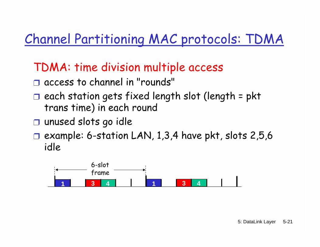
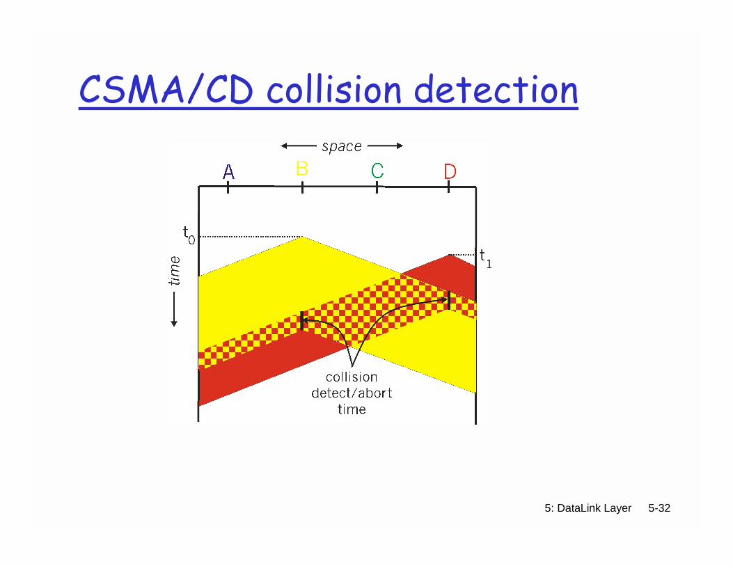
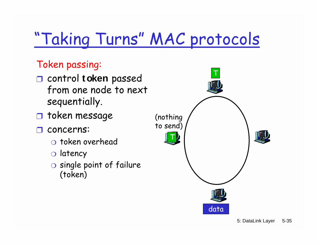
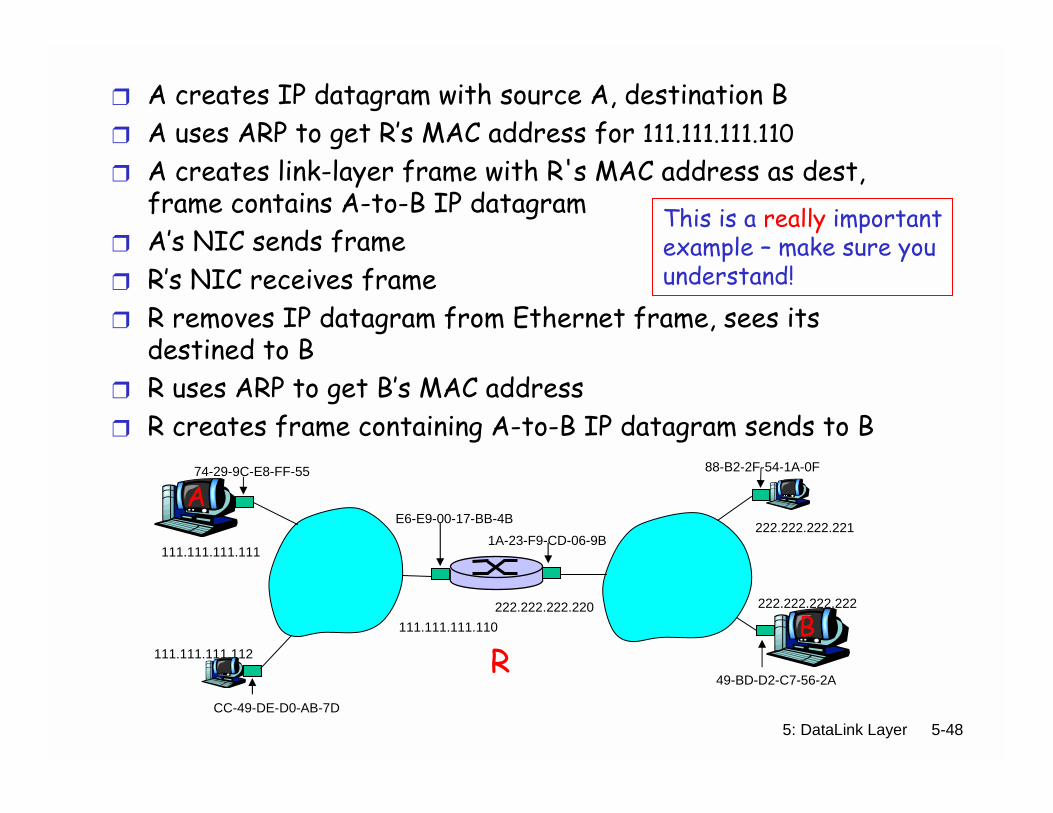
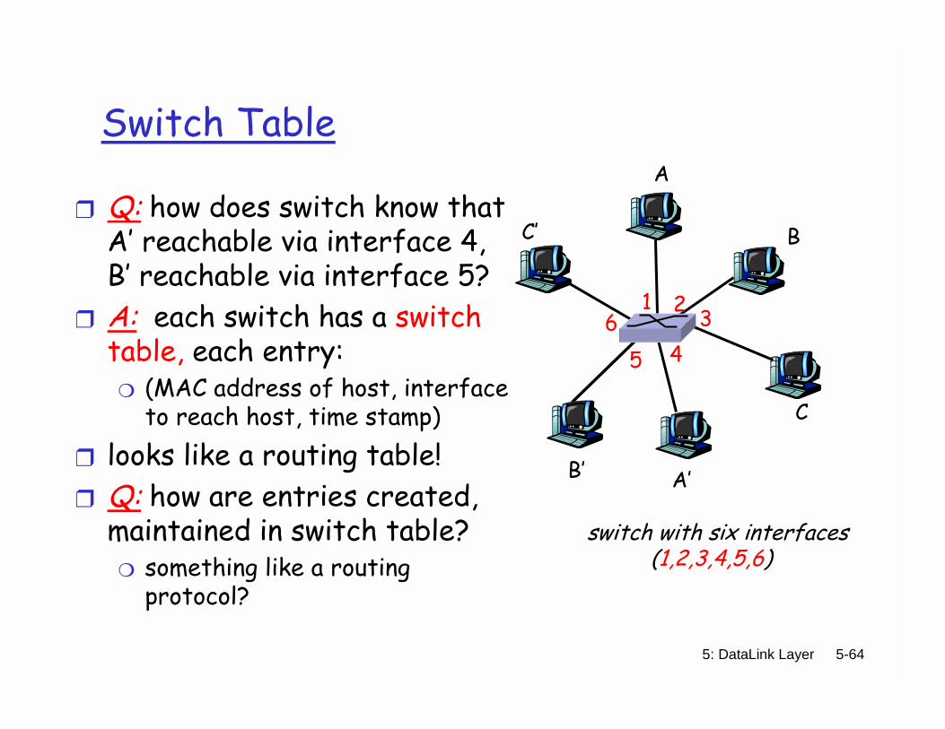
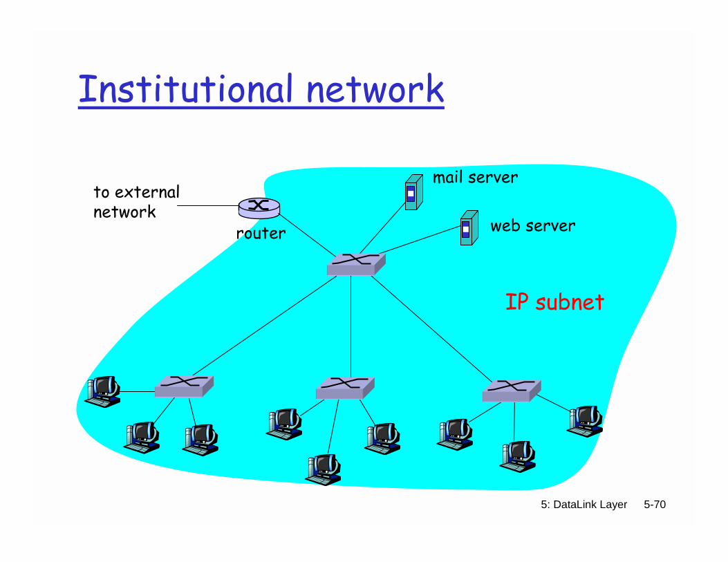
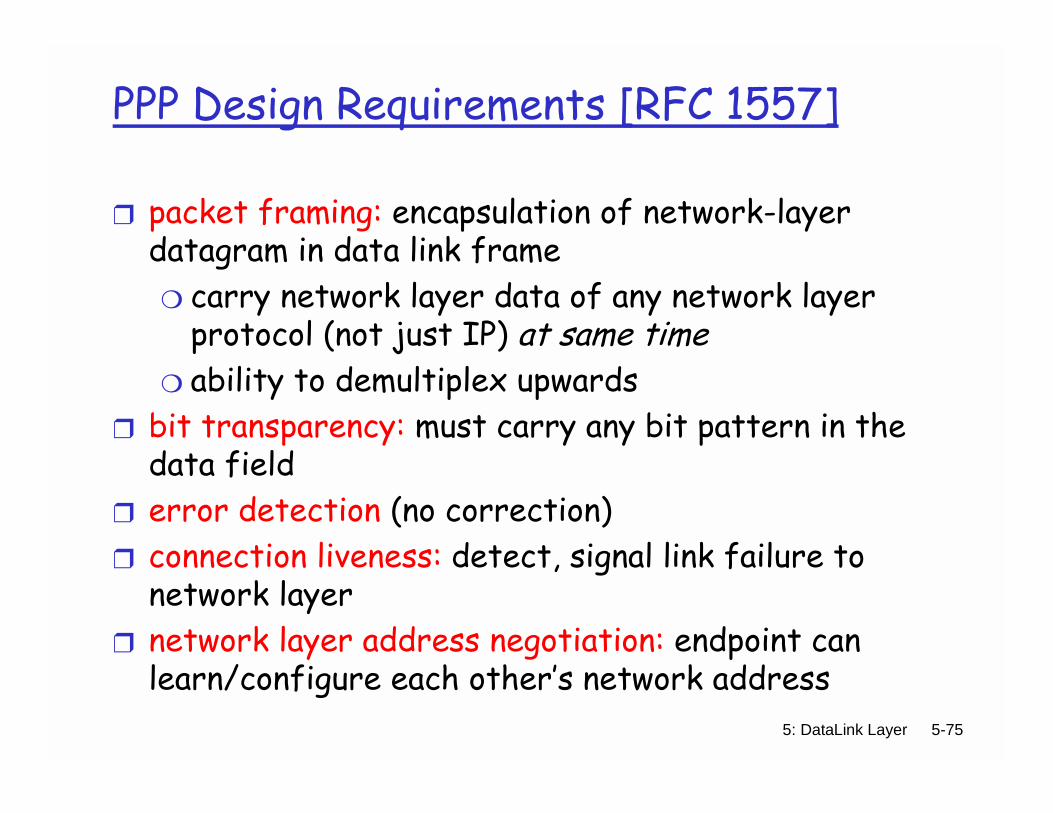
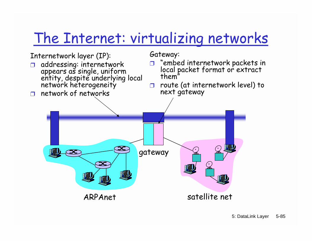
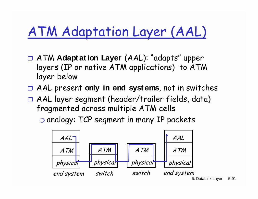
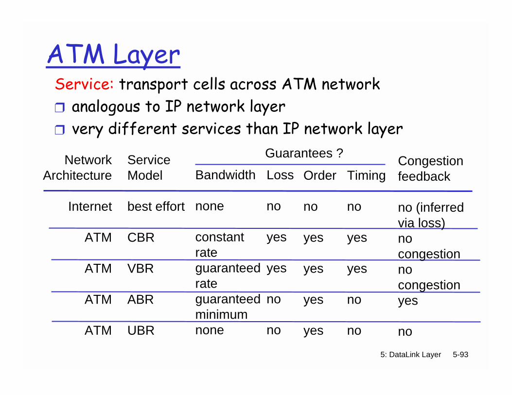
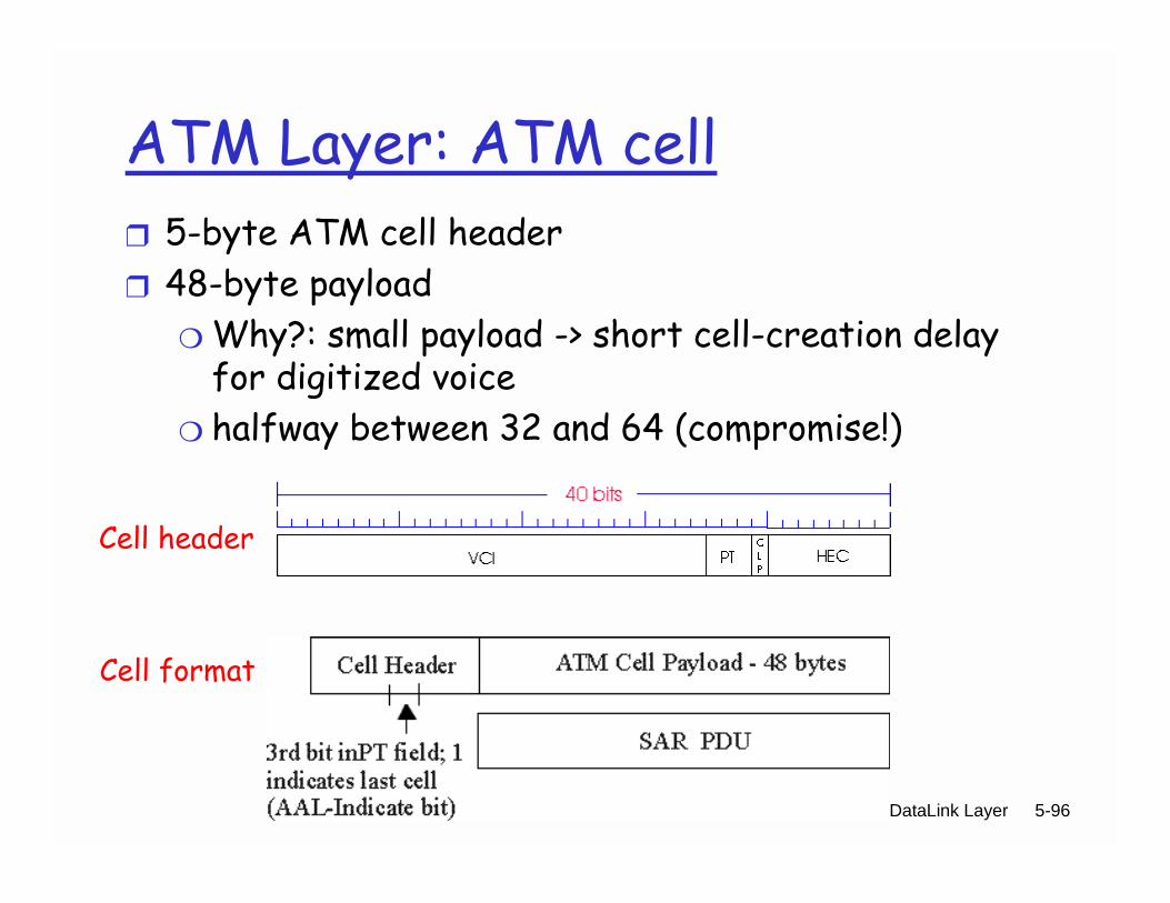
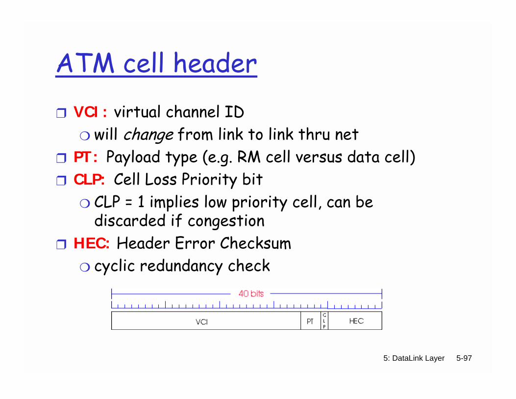
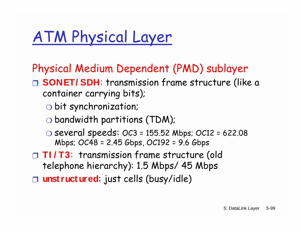

5 DataLink Layer 5-108
Chapter 5 letrsquos take a breath journey down protocol stack complete
(except PHY) solid understanding of networking principles
practice hellip could stop here hellip but lots of interesting
topics wireless multimedia security network management