Link Layer Link Layer: Introduction - Temple Universityjfiore/2016/fall/3329/handouts/... · ·...
26
5: DataLink Layer 5-1 Chapter 5 Link Layer and LANs A note on the use of these ppt slides: Were making these slides freely available to all (faculty, students, readers). Theyre in PowerPoint form so you can add, modify, and delete slides (including this one) and slide content to suit your needs. They obviously represent a lot of work on our part. In return for use, we only ask the following: If you use these slides (e.g., in a class) in substantially unaltered form, that you mention their source (after all, wed like people to use our book!) If you post any slides in substantially unaltered form on a www site, that you note that they are adapted from (or perhaps identical to) our slides, and note our copyright of this material. Thanks and enjoy! JFK/KWR All material copyright 1996-2009 J.F Kurose and K.W. Ross, All Rights Reserved Computer Networking: A Top Down Approach 5 th edition. Jim Kurose, Keith Ross Addison-Wesley, April 2009. 5: DataLink Layer 5-2 Chapter 5: The Data Link Layer Our goals: understand principles behind data link layer services: error detection, correction sharing a broadcast channel: multiple access link layer addressing reliable data transfer, flow control: done! instantiation and implementation of various link layer technologies 5: DataLink Layer 5-3 Link Layer 5.1 Introduction and services 5.2 Error detection and correction 5.3Multiple access protocols 5.4 Link-layer Addressing 5.5 Ethernet 5.6 Link-layer switches 5.7 PPP 5.8 Link virtualization: MPLS 5.9 A day in the life of a web request 5: DataLink Layer 5-4 Link Layer: Introduction Some terminology: hosts and routers are nodes communication channels that connect adjacent nodes along communication path are links wired links wireless links LANs layer-2 packet is a frame, encapsulates datagram data-link layer has responsibility of transferring datagram from one node to adjacent node over a link
Transcript of Link Layer Link Layer: Introduction - Temple Universityjfiore/2016/fall/3329/handouts/... · ·...
5: DataLink Layer 5-1
Chapter 5 Link Layer and LANs
A note on the use of these ppt slides: We re making these slides freely available to all (faculty, students, readers). They re in PowerPoint form so you can add, modify, and delete slides (including this one) and slide content to suit your needs. They obviously represent a lot of work on our part. In return for use, we only ask the following:
If you use these slides (e.g., in a class) in substantially unaltered form, that you mention their source (after all, we d like people to use our book!)
If you post any slides in substantially unaltered form on a www site, that you note that they are adapted from (or perhaps identical to) our slides, and note our copyright of this material.
Thanks and enjoy! JFK/KWR All material copyright 1996-2009 J.F Kurose and K.W. Ross, All Rights Reserved
Computer Networking: A Top Down Approach 5th edition. Jim Kurose, Keith Ross Addison-Wesley, April 2009.
5: DataLink Layer 5-2
Chapter 5: The Data Link Layer Our goals:
understand principles behind data link layer services:
error detection, correction sharing a broadcast channel: multiple access link layer addressing reliable data transfer, flow control: done!
instantiation and implementation of various link layer technologies
5: DataLink Layer 5-3
Link Layer
5.1 Introduction and services 5.2 Error detection and correction 5.3Multiple access protocols 5.4 Link-layer Addressing 5.5 Ethernet
5.6 Link-layer switches 5.7 PPP 5.8 Link virtualization: MPLS 5.9 A day in the life of a web request
5: DataLink Layer 5-4
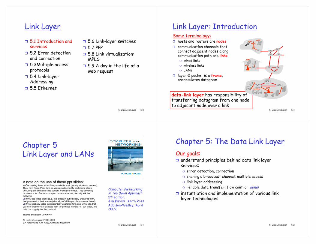
Link Layer: Introduction Some terminology:
hosts and routers are nodes communication channels that connect adjacent nodes along communication path are links
wired links wireless links LANs
layer-2 packet is a frame, encapsulates datagram
data-link layer has responsibility of transferring datagram from one node to adjacent node over a link
5: DataLink Layer 5-5
Link layer: context datagram transferred by different link protocols over different links:
e.g., Ethernet on first link, frame relay on intermediate links, 802.11 on last link
each link protocol provides different services
e.g., may or may not provide rdt over link
transportation analogy trip from Princeton to Lausanne
limo: Princeton to JFK plane: JFK to Geneva train: Geneva to Lausanne
tourist = datagram transport segment = communication link transportation mode = link layer protocol travel agent = routing algorithm
5: DataLink Layer 5-6
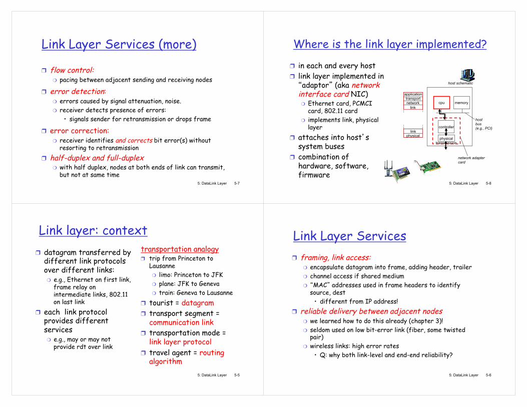
Link Layer Services framing, link access:
encapsulate datagram into frame, adding header, trailer channel access if shared medium MAC addresses used in frame headers to identify
source, dest �• different from IP address!
reliable delivery between adjacent nodes we learned how to do this already (chapter 3)! seldom used on low bit-error link (fiber, some twisted pair) wireless links: high error rates
�• Q: why both link-level and end-end reliability?
5: DataLink Layer 5-7
Link Layer Services (more)
flow control: pacing between adjacent sending and receiving nodes
error detection: errors caused by signal attenuation, noise. receiver detects presence of errors:
�• signals sender for retransmission or drops frame
error correction: receiver identifies and corrects bit error(s) without resorting to retransmission
half-duplex and full-duplex with half duplex, nodes at both ends of link can transmit, but not at same time
5: DataLink Layer 5-8
Where is the link layer implemented?
in each and every host link layer implemented in adaptor (aka network
interface card NIC) Ethernet card, PCMCI card, 802.11 card implements link, physical layer
attaches into host s system buses combination of hardware, software, firmware
controller
physical transmission
cpu memory
host bus (e.g., PCI)
network adapter card
host schematic
application transport network
link
link physical
5: DataLink Layer 5-9
Adaptors Communicating
sending side: encapsulates datagram in frame adds error checking bits, rdt, flow control, etc.
receiving side looks for errors, rdt, flow control, etc extracts datagram, passes to upper layer at receiving side
controller controller
sending host receiving host
datagram datagram
datagram
frame
5: DataLink Layer 5-10
Link Layer
5.1 Introduction and services 5.2 Error detection and correction 5.3Multiple access protocols 5.4 Link-layer Addressing 5.5 Ethernet
5.6 Link-layer switches 5.7 PPP 5.8 Link virtualization: MPLS 5.9 A day in the life of a web request
5: DataLink Layer 5-11
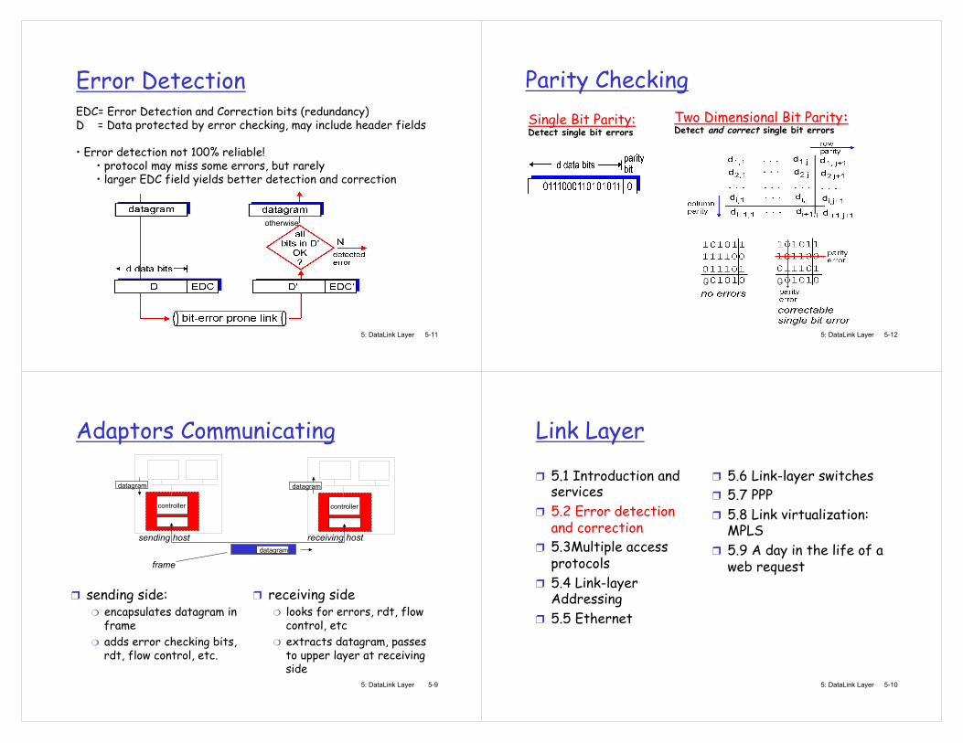
Error Detection EDC= Error Detection and Correction bits (redundancy) D = Data protected by error checking, may include header fields �• Error detection not 100% reliable!
�• protocol may miss some errors, but rarely �• larger EDC field yields better detection and correction
otherwise
5: DataLink Layer 5-12
Parity Checking Single Bit Parity: Detect single bit errors
Two Dimensional Bit Parity: Detect and correct single bit errors
0 0
5: DataLink Layer 5-13
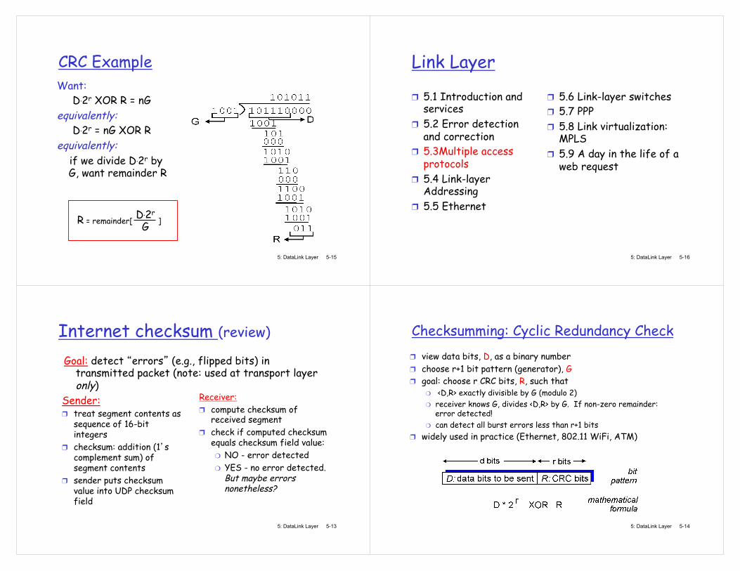
Internet checksum (review)
Sender: treat segment contents as sequence of 16-bit integers checksum: addition (1 s complement sum) of segment contents sender puts checksum value into UDP checksum field
Receiver: compute checksum of received segment check if computed checksum equals checksum field value:
NO - error detected YES - no error detected. But maybe errors nonetheless?
Goal: detect errors (e.g., flipped bits) in transmitted packet (note: used at transport layer only)
5: DataLink Layer 5-14
Checksumming: Cyclic Redundancy Check view data bits, D, as a binary number choose r+1 bit pattern (generator), G goal: choose r CRC bits, R, such that
<D,R> exactly divisible by G (modulo 2) receiver knows G, divides <D,R> by G. If non-zero remainder: error detected! can detect all burst errors less than r+1 bits
widely used in practice (Ethernet, 802.11 WiFi, ATM)
5: DataLink Layer 5-15
CRC Example Want:
D.2r XOR R = nG equivalently:
D.2r = nG XOR R equivalently: if we divide D.2r by
G, want remainder R
R = remainder[ ] D.2r
G
5: DataLink Layer 5-16
Link Layer
5.1 Introduction and services 5.2 Error detection and correction 5.3Multiple access protocols 5.4 Link-layer Addressing 5.5 Ethernet
5.6 Link-layer switches 5.7 PPP 5.8 Link virtualization: MPLS 5.9 A day in the life of a web request
5: DataLink Layer 5-17
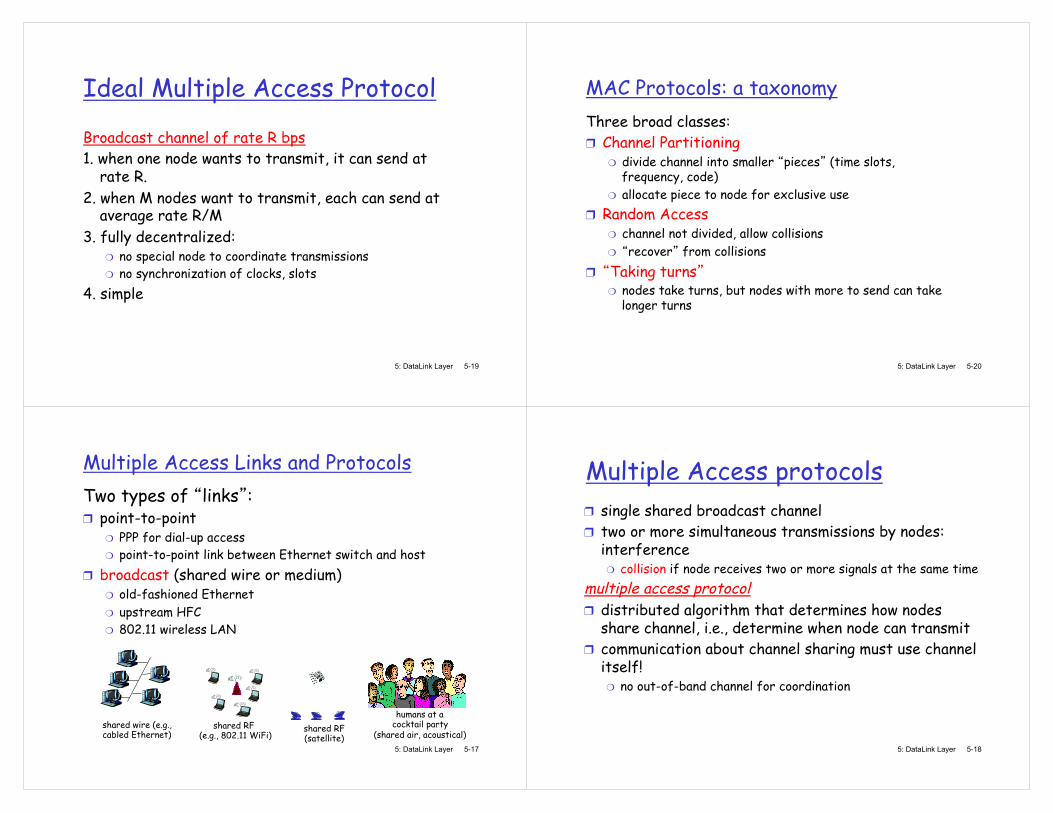
Multiple Access Links and Protocols Two types of links :
point-to-point PPP for dial-up access point-to-point link between Ethernet switch and host
broadcast (shared wire or medium) old-fashioned Ethernet upstream HFC 802.11 wireless LAN
shared wire (e.g., cabled Ethernet)
shared RF (e.g., 802.11 WiFi)
shared RF (satellite)
humans at a cocktail party
(shared air, acoustical) 5: DataLink Layer 5-18
Multiple Access protocols single shared broadcast channel two or more simultaneous transmissions by nodes: interference
collision if node receives two or more signals at the same time multiple access protocol
distributed algorithm that determines how nodes share channel, i.e., determine when node can transmit communication about channel sharing must use channel itself!
no out-of-band channel for coordination
5: DataLink Layer 5-19
Ideal Multiple Access Protocol
Broadcast channel of rate R bps 1. when one node wants to transmit, it can send at
rate R. 2. when M nodes want to transmit, each can send at
average rate R/M 3. fully decentralized:
no special node to coordinate transmissions no synchronization of clocks, slots
4. simple
5: DataLink Layer 5-20
MAC Protocols: a taxonomy Three broad classes:
Channel Partitioning divide channel into smaller pieces (time slots, frequency, code) allocate piece to node for exclusive use
Random Access channel not divided, allow collisions recover from collisions
Taking turns nodes take turns, but nodes with more to send can take longer turns
5: DataLink Layer 5-21
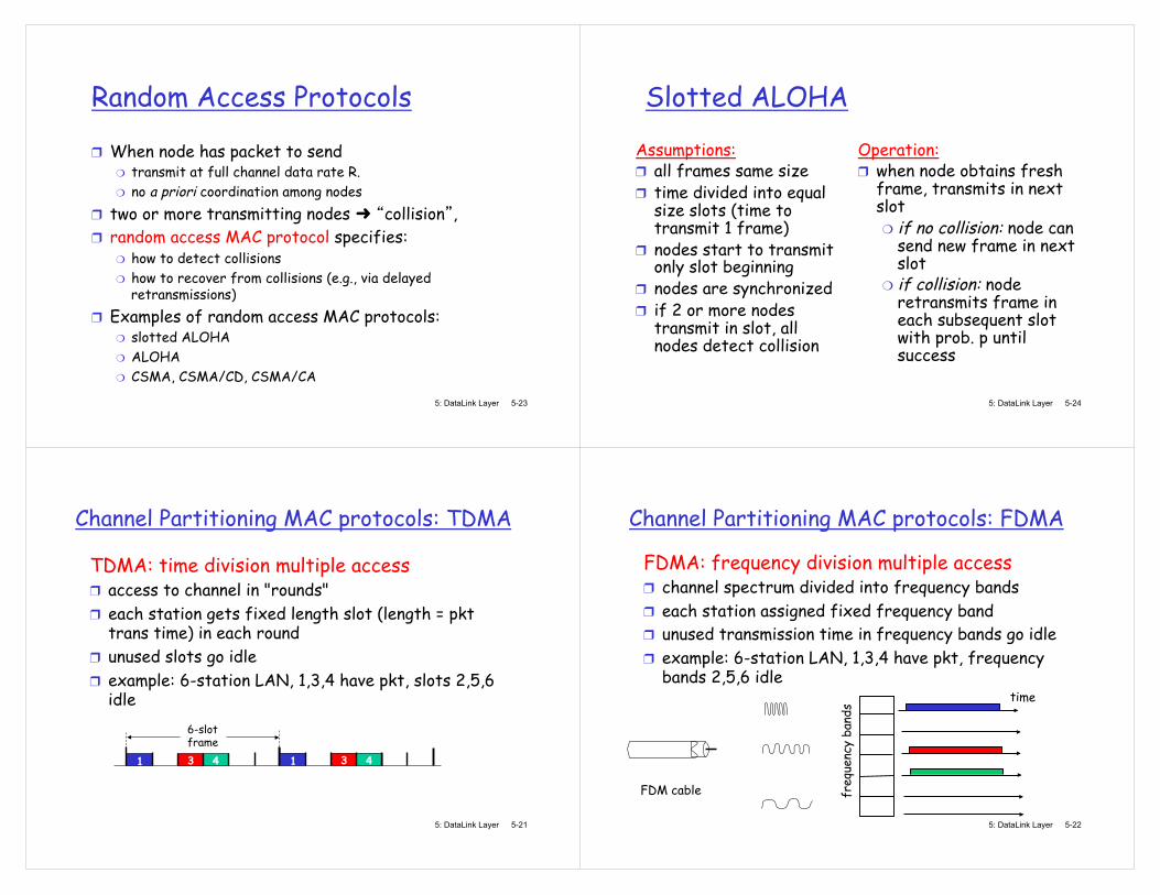
Channel Partitioning MAC protocols: TDMA TDMA: time division multiple access
access to channel in "rounds" each station gets fixed length slot (length = pkt trans time) in each round unused slots go idle example: 6-station LAN, 1,3,4 have pkt, slots 2,5,6 idle
1 3 4 1 3 4
6-slot frame
5: DataLink Layer 5-22
Channel Partitioning MAC protocols: FDMA FDMA: frequency division multiple access
channel spectrum divided into frequency bands each station assigned fixed frequency band unused transmission time in frequency bands go idle example: 6-station LAN, 1,3,4 have pkt, frequency bands 2,5,6 idle
freq
uenc
y ba
nds
time
FDM cable
5: DataLink Layer 5-23
Random Access Protocols
When node has packet to send transmit at full channel data rate R. no a priori coordination among nodes
two or more transmitting nodes collision , random access MAC protocol specifies:
how to detect collisions how to recover from collisions (e.g., via delayed retransmissions)
Examples of random access MAC protocols: slotted ALOHA ALOHA CSMA, CSMA/CD, CSMA/CA
5: DataLink Layer 5-24
Slotted ALOHA
Assumptions: all frames same size time divided into equal size slots (time to transmit 1 frame) nodes start to transmit only slot beginning nodes are synchronized if 2 or more nodes transmit in slot, all nodes detect collision
Operation: when node obtains fresh frame, transmits in next slot
if no collision: node can send new frame in next slot if collision: node retransmits frame in each subsequent slot with prob. p until success

5: DataLink Layer 5-25
Slotted ALOHA
Pros single active node can continuously transmit at full rate of channel highly decentralized: only slots in nodes need to be in sync simple
Cons collisions, wasting slots idle slots nodes may be able to detect collision in less than time to transmit packet clock synchronization
5: DataLink Layer 5-26
Slotted Aloha efficiency
suppose: N nodes with many frames to send, each transmits in slot with probability p prob that given node has success in a slot = p(1-p)N-1
prob that any node has a success = Np(1-p)N-1
max efficiency: find p* that maximizes Np(1-p)N-1
for many nodes, take limit of Np*(1-p*)N-1
as N goes to infinity, gives:
Max efficiency = 1/e = .37
Efficiency : long-run fraction of successful slots (many nodes, all with many frames to send)
At best: channel used for useful transmissions 37% of time! !
5: DataLink Layer 5-27
Pure (unslotted) ALOHA unslotted Aloha: simpler, no synchronization when frame first arrives
transmit immediately collision probability increases:
frame sent at t0 collides with other frames sent in [t0-1,t0+1]
5: DataLink Layer 5-28
Pure Aloha efficiency P(success by given node) = P(node transmits) . P(no other node transmits in [p0-1,p0] . P(no other node transmits in [p0-1,p0] = p . (1-p)N-1 . (1-p)N-1
= p . (1-p)2(N-1) �… choosing optimum p and then letting n -> infty ...
= 1/(2e) = .18
even worse than slotted Aloha!
5: DataLink Layer 5-29
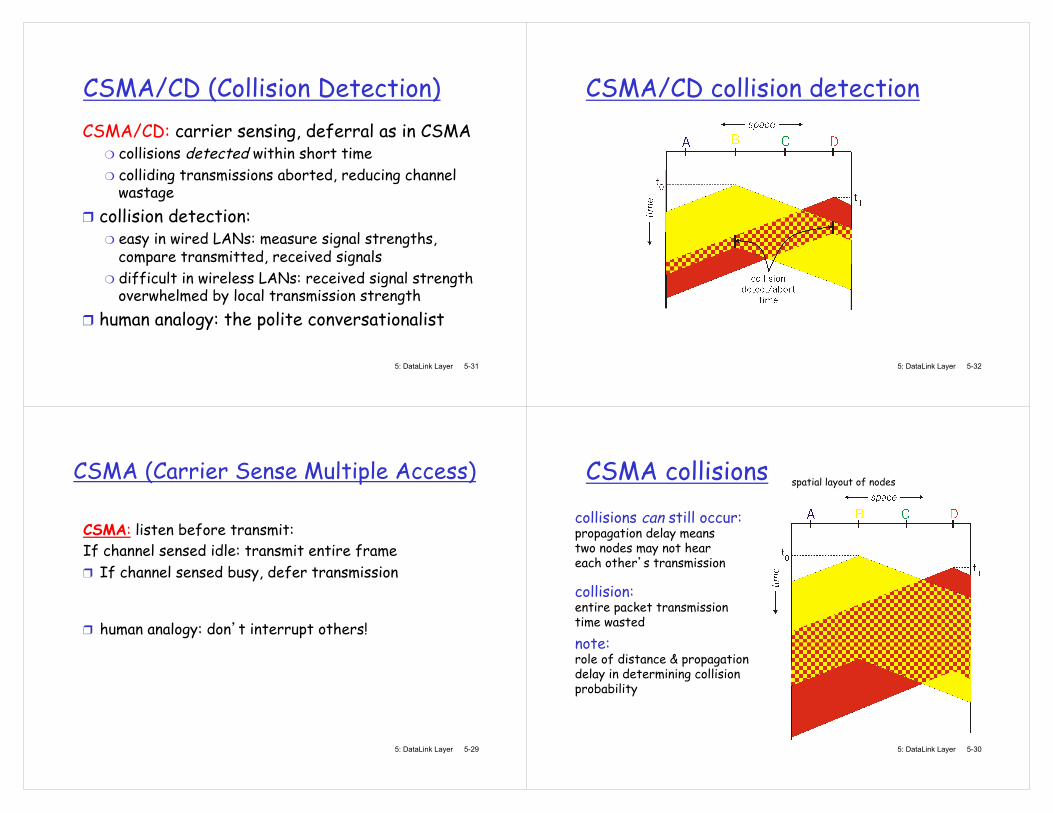
CSMA (Carrier Sense Multiple Access)
CSMA: listen before transmit: If channel sensed idle: transmit entire frame
If channel sensed busy, defer transmission human analogy: don t interrupt others!
5: DataLink Layer 5-30
CSMA collisions collisions can still occur: propagation delay means two nodes may not hear each other s transmission
collision: entire packet transmission time wasted
spatial layout of nodes
note: role of distance & propagation delay in determining collision probability
5: DataLink Layer 5-31
CSMA/CD (Collision Detection) CSMA/CD: carrier sensing, deferral as in CSMA
collisions detected within short time colliding transmissions aborted, reducing channel wastage
collision detection: easy in wired LANs: measure signal strengths, compare transmitted, received signals difficult in wireless LANs: received signal strength overwhelmed by local transmission strength
human analogy: the polite conversationalist
5: DataLink Layer 5-32
CSMA/CD collision detection
5: DataLink Layer 5-33
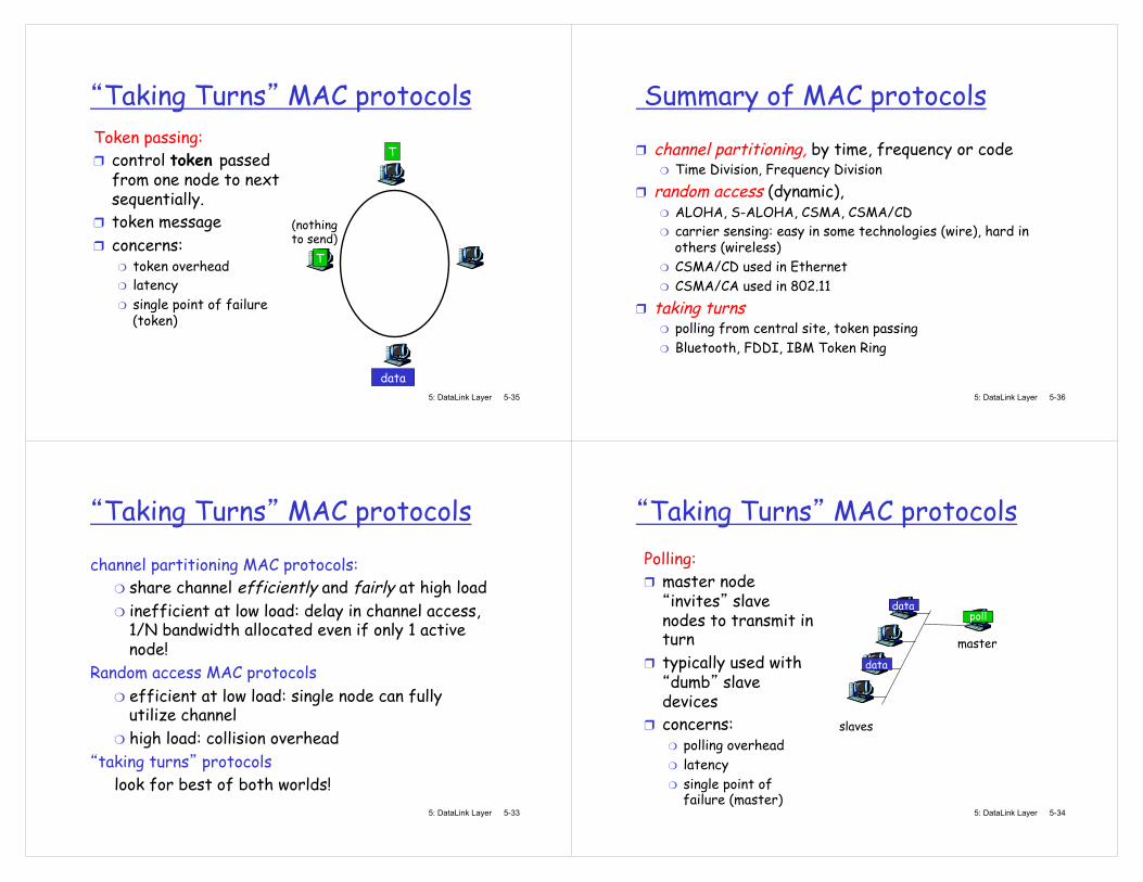
Taking Turns MAC protocols
channel partitioning MAC protocols: share channel efficiently and fairly at high load inefficient at low load: delay in channel access, 1/N bandwidth allocated even if only 1 active node!
Random access MAC protocols efficient at low load: single node can fully utilize channel high load: collision overhead
taking turns protocols look for best of both worlds!
5: DataLink Layer 5-34
Taking Turns MAC protocols Polling:
master node invites slave
nodes to transmit in turn typically used with dumb slave
devices concerns:
polling overhead latency single point of failure (master)
master
slaves
poll
data
data
5: DataLink Layer 5-35
Taking Turns MAC protocols Token passing:
control token passed from one node to next sequentially. token message concerns:
token overhead latency single point of failure (token)
T
data
(nothing to send)
T
5: DataLink Layer 5-36
Summary of MAC protocols
channel partitioning, by time, frequency or code Time Division, Frequency Division
random access (dynamic), ALOHA, S-ALOHA, CSMA, CSMA/CD carrier sensing: easy in some technologies (wire), hard in others (wireless) CSMA/CD used in Ethernet CSMA/CA used in 802.11
taking turns polling from central site, token passing Bluetooth, FDDI, IBM Token Ring
5: DataLink Layer 5-37
Link Layer
5.1 Introduction and services 5.2 Error detection and correction 5.3Multiple access protocols 5.4 Link-Layer Addressing 5.5 Ethernet
5.6 Link-layer switches 5.7 PPP 5.8 Link virtualization: MPLS 5.9 A day in the life of a web request
5: DataLink Layer 5-38
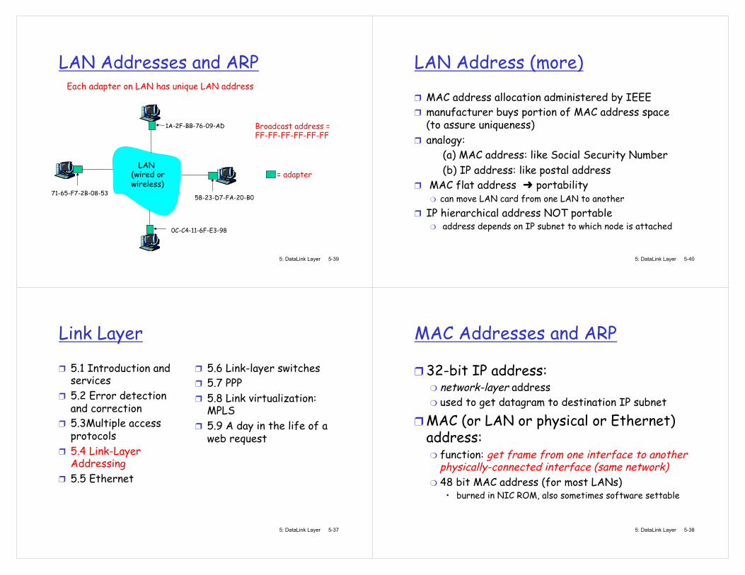
MAC Addresses and ARP
32-bit IP address: network-layer address used to get datagram to destination IP subnet
MAC (or LAN or physical or Ethernet) address:
function: get frame from one interface to another physically-connected interface (same network) 48 bit MAC address (for most LANs)
�• burned in NIC ROM, also sometimes software settable
5: DataLink Layer 5-39
LAN Addresses and ARP Each adapter on LAN has unique LAN address
Broadcast address = FF-FF-FF-FF-FF-FF
= adapter
1A-2F-BB-76-09-AD
58-23-D7-FA-20-B0
0C-C4-11-6F-E3-98
71-65-F7-2B-08-53
LAN (wired or wireless)
5: DataLink Layer 5-40
LAN Address (more)
MAC address allocation administered by IEEE manufacturer buys portion of MAC address space (to assure uniqueness) analogy:
(a) MAC address: like Social Security Number (b) IP address: like postal address
MAC flat address portability can move LAN card from one LAN to another
IP hierarchical address NOT portable address depends on IP subnet to which node is attached

5: DataLink Layer 5-41
ARP: Address Resolution Protocol
Each IP node (host, router) on LAN has ARP table ARP table: IP/MAC address mappings for some LAN nodes
< IP address; MAC address; TTL> TTL (Time To Live): time after which address mapping will be forgotten (typically 20 min)
Question: how to determine MAC address of B knowing B s IP address?
1A-2F-BB-76-09-AD
58-23-D7-FA-20-B0
0C-C4-11-6F-E3-98
71-65-F7-2B-08-53
LAN
137.196.7.23
137.196.7.78
137.196.7.14
137.196.7.88
5: DataLink Layer 5-42
ARP protocol: Same LAN (network)
A wants to send datagram to B, and B s MAC address not in A s ARP table. A broadcasts ARP query packet, containing B's IP address
dest MAC address = FF-FF-FF-FF-FF-FF all machines on LAN receive ARP query
B receives ARP packet, replies to A with its (B's) MAC address
frame sent to A s MAC address (unicast)
A caches (saves) IP-to-MAC address pair in its ARP table until information becomes old (times out)
soft state: information that times out (goes away) unless refreshed
ARP is plug-and-play : nodes create their ARP tables without intervention from net administrator
5: DataLink Layer 5-43
Addressing: routing to another LAN
R
1A-23-F9-CD-06-9B
222.222.222.220 111.111.111.110
E6-E9-00-17-BB-4B
CC-49-DE-D0-AB-7D
111.111.111.112
111.111.111.111
A 74-29-9C-E8-FF-55
222.222.222.221
88-B2-2F-54-1A-0F
B 222.222.222.222
49-BD-D2-C7-56-2A
walkthrough: send datagram from A to B via R assume A knows B s IP address
two ARP tables in router R, one for each IP network (LAN)
5: DataLink Layer 5-44
A creates IP datagram with source A, destination B A uses ARP to get R s MAC address for 111.111.111.110 A creates link-layer frame with R's MAC address as dest, frame contains A-to-B IP datagram A s NIC sends frame R s NIC receives frame R removes IP datagram from Ethernet frame, sees its destined to B R uses ARP to get B s MAC address R creates frame containing A-to-B IP datagram sends to B
R
1A-23-F9-CD-06-9B
222.222.222.220 111.111.111.110
E6-E9-00-17-BB-4B
CC-49-DE-D0-AB-7D
111.111.111.112
111.111.111.111
A 74-29-9C-E8-FF-55
222.222.222.221
88-B2-2F-54-1A-0F
B 222.222.222.222
49-BD-D2-C7-56-2A
This is a really important example �– make sure you understand!
5: DataLink Layer 5-45
Link Layer
5.1 Introduction and services 5.2 Error detection and correction 5.3Multiple access protocols 5.4 Link-Layer Addressing 5.5 Ethernet
5.6 Link-layer switches 5.7 PPP 5.8 Link virtualization: MPLS 5.9 A day in the life of a web request
5: DataLink Layer 5-46
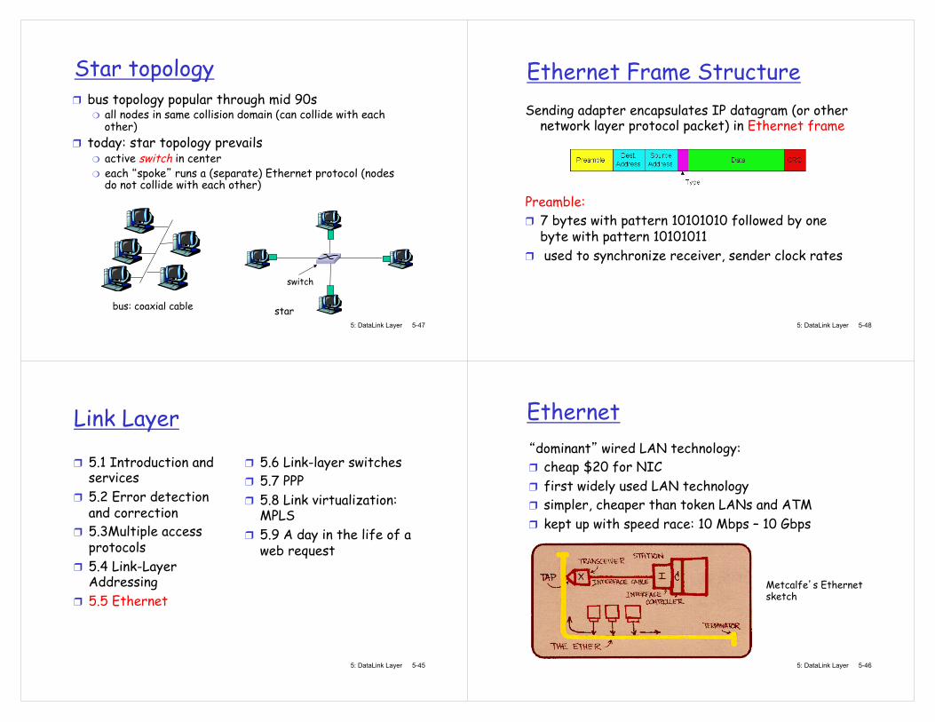
Ethernet dominant wired LAN technology:
cheap $20 for NIC first widely used LAN technology simpler, cheaper than token LANs and ATM kept up with speed race: 10 Mbps �– 10 Gbps
Metcalfe s Ethernet sketch
5: DataLink Layer 5-47
Star topology bus topology popular through mid 90s
all nodes in same collision domain (can collide with each other)
today: star topology prevails active switch in center each spoke runs a (separate) Ethernet protocol (nodes do not collide with each other)
switch
bus: coaxial cable star 5: DataLink Layer 5-48
Ethernet Frame Structure Sending adapter encapsulates IP datagram (or other
network layer protocol packet) in Ethernet frame
Preamble:
7 bytes with pattern 10101010 followed by one byte with pattern 10101011 used to synchronize receiver, sender clock rates
5: DataLink Layer 5-49
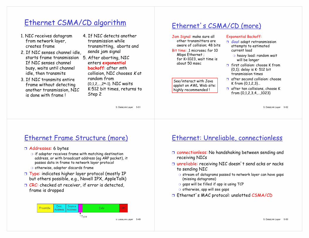
Ethernet Frame Structure (more) Addresses: 6 bytes
if adapter receives frame with matching destination address, or with broadcast address (eg ARP packet), it passes data in frame to network layer protocol otherwise, adapter discards frame
Type: indicates higher layer protocol (mostly IP but others possible, e.g., Novell IPX, AppleTalk) CRC: checked at receiver, if error is detected, frame is dropped
5: DataLink Layer 5-50
Ethernet: Unreliable, connectionless
connectionless: No handshaking between sending and receiving NICs unreliable: receiving NIC doesn t send acks or nacks to sending NIC
stream of datagrams passed to network layer can have gaps (missing datagrams) gaps will be filled if app is using TCP otherwise, app will see gaps
Ethernet s MAC protocol: unslotted CSMA/CD
5: DataLink Layer 5-51
Ethernet CSMA/CD algorithm 1. NIC receives datagram
from network layer, creates frame
2. If NIC senses channel idle, starts frame transmission If NIC senses channel busy, waits until channel idle, then transmits
3. If NIC transmits entire frame without detecting another transmission, NIC is done with frame !
4. If NIC detects another transmission while transmitting, aborts and sends jam signal
5. After aborting, NIC enters exponential backoff: after mth collision, NIC chooses K at random from {0,1,2,�…,2m-1}. NIC waits K·512 bit times, returns to Step 2
5: DataLink Layer 5-52
Ethernet s CSMA/CD (more) Jam Signal: make sure all
other transmitters are aware of collision; 48 bits
Bit time: .1 microsec for 10 Mbps Ethernet ; for K=1023, wait time is about 50 msec
Exponential Backoff: Goal: adapt retransmission attempts to estimated current load
heavy load: random wait will be longer
first collision: choose K from {0,1}; delay is K· 512 bit transmission times after second collision: choose K from {0,1,2,3}�… after ten collisions, choose K from {0,1,2,3,4,�…,1023}
See/interact with Java applet on AWL Web site: highly recommended !
5: DataLink Layer 5-53
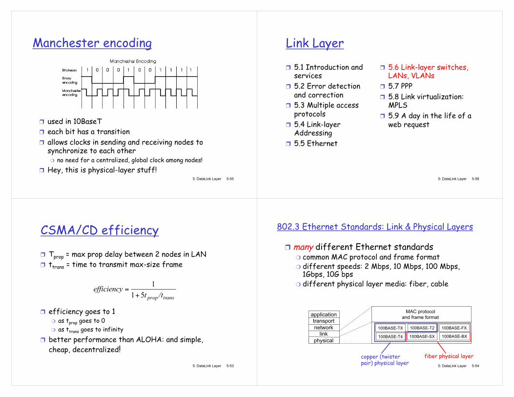
CSMA/CD efficiency
Tprop = max prop delay between 2 nodes in LAN ttrans = time to transmit max-size frame
efficiency goes to 1 as tprop goes to 0 as ttrans goes to infinity
better performance than ALOHA: and simple, cheap, decentralized!
transprop /ttefficiency
511
+=
5: DataLink Layer 5-54
802.3 Ethernet Standards: Link & Physical Layers
many different Ethernet standards common MAC protocol and frame format different speeds: 2 Mbps, 10 Mbps, 100 Mbps, 1Gbps, 10G bps different physical layer media: fiber, cable
application transport network
link physical
MAC protocol and frame format
100BASE-TX
100BASE-T4
100BASE-FX 100BASE-T2
100BASE-SX 100BASE-BX
fiber physical layer copper (twister pair) physical layer
5: DataLink Layer 5-55
Manchester encoding
used in 10BaseT each bit has a transition allows clocks in sending and receiving nodes to synchronize to each other
no need for a centralized, global clock among nodes! Hey, this is physical-layer stuff!
5: DataLink Layer 5-56
Link Layer
5.1 Introduction and services 5.2 Error detection and correction 5.3 Multiple access protocols 5.4 Link-layer Addressing 5.5 Ethernet
5.6 Link-layer switches, LANs, VLANs 5.7 PPP 5.8 Link virtualization: MPLS 5.9 A day in the life of a web request
5: DataLink Layer 5-57
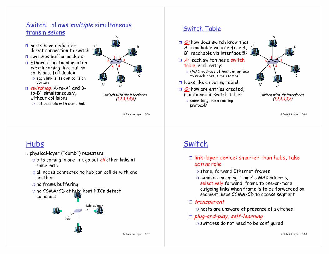
Hubs �… physical-layer ( dumb ) repeaters:
bits coming in one link go out all other links at same rate all nodes connected to hub can collide with one another no frame buffering no CSMA/CD at hub: host NICs detect collisions
twisted pair
hub
5: DataLink Layer 5-58
Switch link-layer device: smarter than hubs, take active role
store, forward Ethernet frames examine incoming frame s MAC address, selectively forward frame to one-or-more outgoing links when frame is to be forwarded on segment, uses CSMA/CD to access segment
transparent hosts are unaware of presence of switches
plug-and-play, self-learning switches do not need to be configured
5: DataLink Layer 5-59
Switch: allows multiple simultaneous transmissions
hosts have dedicated, direct connection to switch switches buffer packets Ethernet protocol used on each incoming link, but no collisions; full duplex
each link is its own collision domain
switching: A-to-A and B-to-B simultaneously, without collisions
not possible with dumb hub
A
A
B
B
C
C
switch with six interfaces (1,2,3,4,5,6)
1 2 3 4 5
6
5: DataLink Layer 5-60
Switch Table
Q: how does switch know that A reachable via interface 4, B reachable via interface 5? A: each switch has a switch table, each entry:
(MAC address of host, interface to reach host, time stamp)
looks like a routing table! Q: how are entries created, maintained in switch table?
something like a routing protocol?
A
A
B
B
C
C
switch with six interfaces (1,2,3,4,5,6)
1 2 3 4 5
6
5: DataLink Layer 5-61
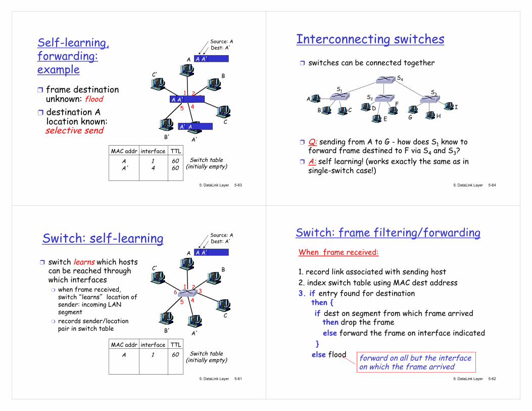
Switch: self-learning switch learns which hosts can be reached through which interfaces
when frame received, switch learns location of sender: incoming LAN segment records sender/location pair in switch table
A
A
B
B
C
C
1 2 3 4 5
6
A A
Source: A Dest: A
MAC addr interface TTL Switch table
(initially empty) A 1 60
5: DataLink Layer 5-62
Switch: frame filtering/forwarding When frame received:
1. record link associated with sending host 2. index switch table using MAC dest address 3. if entry found for destination
then { if dest on segment from which frame arrived
then drop the frame else forward the frame on interface indicated } else flood
forward on all but the interface on which the frame arrived
5: DataLink Layer 5-63
Self-learning, forwarding: example
A
A
B
B
C
C
1 2 3 4 5
6
A A
Source: A Dest: A
MAC addr interface TTL Switch table
(initially empty) A 1 60
A A A A A A A A A A frame destination unknown: flood
A A
destination A location known:
A 4 60
selective send
5: DataLink Layer 5-64
Interconnecting switches switches can be connected together
A
B
Q: sending from A to G - how does S1 know to forward frame destined to F via S4 and S3? A: self learning! (works exactly the same as in single-switch case!)
S1
C D
E
F S2
S4
S3
H I
G
5: DataLink Layer 5-65
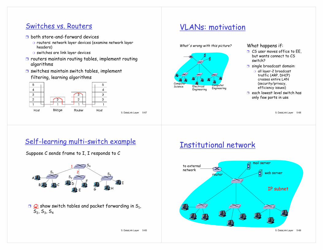
Self-learning multi-switch example Suppose C sends frame to I, I responds to C
Q: show switch tables and packet forwarding in S1, S2, S3, S4
A
B
S1
C D
E
F S2
S4
S3
H I
G
1 2
5: DataLink Layer 5-66
Institutional network
to external network
router
IP subnet
mail server
web server
5: DataLink Layer 5-67
Switches vs. Routers both store-and-forward devices
routers: network layer devices (examine network layer headers) switches are link layer devices
routers maintain routing tables, implement routing algorithms switches maintain switch tables, implement filtering, learning algorithms
5: DataLink Layer 5-68
VLANs: motivation
What happens if: CS user moves office to EE, but wants connect to CS switch? single broadcast domain:
all layer-2 broadcast traffic (ARP, DHCP) crosses entire LAN (security/privacy, efficiency issues)
each lowest level switch has only few ports in use
Computer Science Electrical
Engineering Computer Engineering
What s wrong with this picture?

5: DataLink Layer 5-69
VLANs Port-based VLAN: switch ports grouped (by switch management software) so that single physical switch �…�…
Switch(es) supporting VLAN capabilities can be configured to define multiple virtual LANS over single physical LAN infrastructure.
Virtual Local Area Network
1
8
9
16 10 2
7
Electrical Engineering (VLAN ports 1-8)
Computer Science (VLAN ports 9-15)
15
Electrical Engineering (VLAN ports 1-8)
1
8 2
7 9
16 10
15
Computer Science (VLAN ports 9-16)
�… operates as multiple virtual switches
5: DataLink Layer 5-70
Port-based VLAN
1
8
9
16 10 2
7
Electrical Engineering (VLAN ports 1-8)
Computer Science (VLAN ports 9-15)
15
traffic isolation: frames to/from ports 1-8 can only reach ports 1-8
can also define VLAN based on MAC addresses of endpoints, rather than switch port
dynamic membership: ports can be dynamically assigned among VLANs
router
forwarding between VLANS: done via routing (just as with separate switches)
in practice vendors sell combined switches plus routers
5: DataLink Layer 5-71
VLANS spanning multiple switches
trunk port: carries frames between VLANS defined over multiple physical switches
frames forwarded within VLAN between switches can t be vanilla 802.1 frames (must carry VLAN ID info) 802.1q protocol adds/removed additional header fields for frames forwarded between trunk ports
1
8
9
10 2
7
Electrical Engineering (VLAN ports 1-8)
Computer Science (VLAN ports 9-15)
15
2
7 3
Ports 2,3,5 belong to EE VLAN Ports 4,6,7,8 belong to CS VLAN
5
4 6 8 16
1
5: DataLink Layer 5-72
Type
2-byte Tag Protocol Identifier (value: 81-00)
Tag Control Information (12 bit VLAN ID field, 3 bit priority field like IP TOS)
Recomputed CRC
802.1Q VLAN frame format
802.1 frame
802.1Q frame
5: DataLink Layer 5-73
Link Layer
5.1 Introduction and services 5.2 Error detection and correction 5.3Multiple access protocols 5.4 Link-Layer Addressing 5.5 Ethernet
5.6 Link-layer switches 5.7 PPP 5.8 Link virtualization: MPLS 5.9 A day in the life of a web request
5: DataLink Layer 5-74
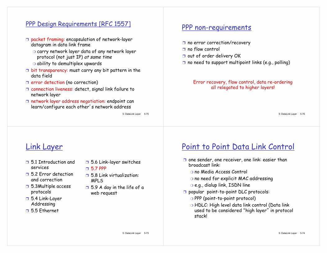
Point to Point Data Link Control one sender, one receiver, one link: easier than broadcast link:
no Media Access Control no need for explicit MAC addressing e.g., dialup link, ISDN line
popular point-to-point DLC protocols: PPP (point-to-point protocol) HDLC: High level data link control (Data link used to be considered high layer in protocol stack!
5: DataLink Layer 5-75
PPP Design Requirements [RFC 1557]
packet framing: encapsulation of network-layer datagram in data link frame
carry network layer data of any network layer protocol (not just IP) at same time ability to demultiplex upwards
bit transparency: must carry any bit pattern in the data field error detection (no correction) connection liveness: detect, signal link failure to network layer network layer address negotiation: endpoint can learn/configure each other s network address
5: DataLink Layer 5-76
PPP non-requirements
no error correction/recovery no flow control out of order delivery OK no need to support multipoint links (e.g., polling)
Error recovery, flow control, data re-ordering all relegated to higher layers!
5: DataLink Layer 5-77
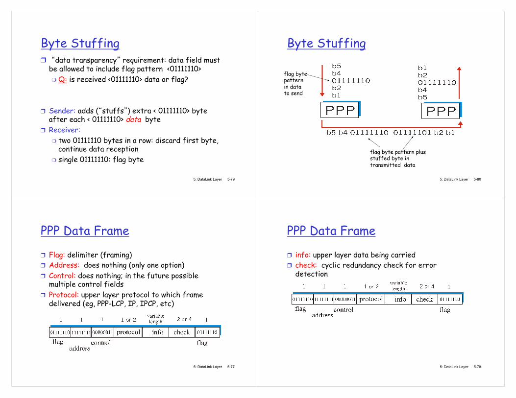
PPP Data Frame
Flag: delimiter (framing) Address: does nothing (only one option) Control: does nothing; in the future possible multiple control fields Protocol: upper layer protocol to which frame delivered (eg, PPP-LCP, IP, IPCP, etc)
5: DataLink Layer 5-78
PPP Data Frame
info: upper layer data being carried check: cyclic redundancy check for error detection
5: DataLink Layer 5-79
Byte Stuffing data transparency requirement: data field must be allowed to include flag pattern <01111110>
Q: is received <01111110> data or flag?
Sender: adds ( stuffs ) extra < 01111110> byte after each < 01111110> data byte Receiver:
two 01111110 bytes in a row: discard first byte, continue data reception single 01111110: flag byte
5: DataLink Layer 5-80
Byte Stuffing
flag byte pattern in data to send
flag byte pattern plus stuffed byte in transmitted data
5: DataLink Layer 5-81
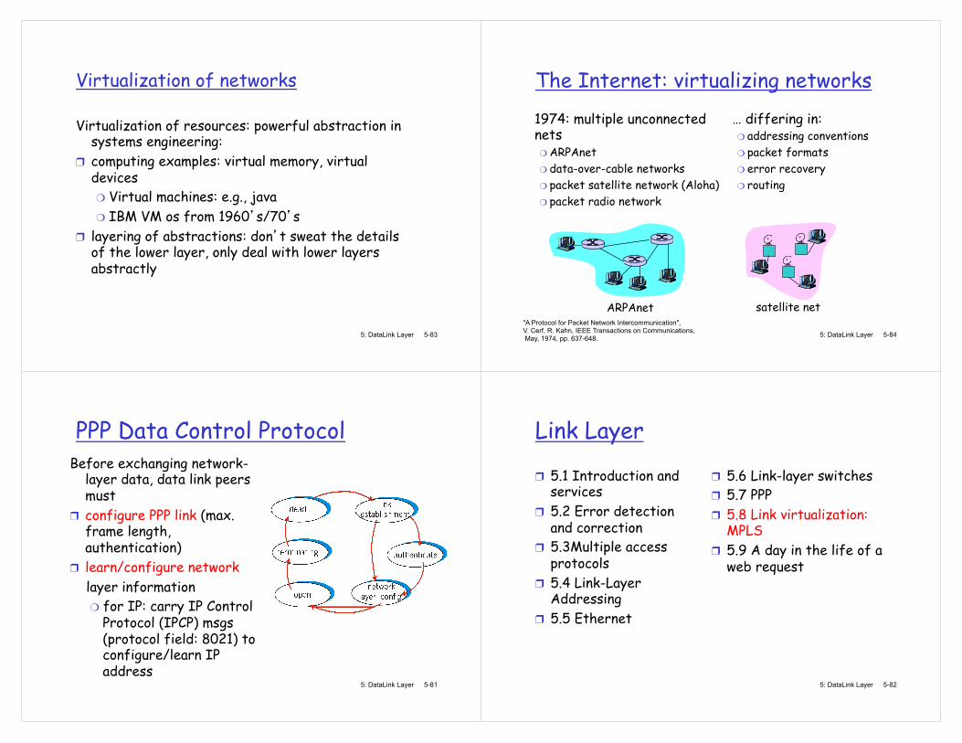
PPP Data Control Protocol Before exchanging network-
layer data, data link peers must configure PPP link (max. frame length, authentication) learn/configure network
layer information for IP: carry IP Control Protocol (IPCP) msgs (protocol field: 8021) to configure/learn IP address
5: DataLink Layer 5-82
Link Layer
5.1 Introduction and services 5.2 Error detection and correction 5.3Multiple access protocols 5.4 Link-Layer Addressing 5.5 Ethernet
5.6 Link-layer switches 5.7 PPP 5.8 Link virtualization: MPLS 5.9 A day in the life of a web request
5: DataLink Layer 5-83
Virtualization of networks
Virtualization of resources: powerful abstraction in systems engineering: computing examples: virtual memory, virtual devices
Virtual machines: e.g., java IBM VM os from 1960 s/70 s
layering of abstractions: don t sweat the details of the lower layer, only deal with lower layers abstractly
5: DataLink Layer 5-84
The Internet: virtualizing networks
1974: multiple unconnected nets
ARPAnet data-over-cable networks packet satellite network (Aloha) packet radio network
�… differing in: addressing conventions packet formats error recovery routing
ARPAnet satellite net "A Protocol for Packet Network Intercommunication", V. Cerf, R. Kahn, IEEE Transactions on Communications, May, 1974, pp. 637-648.
5: DataLink Layer 5-85
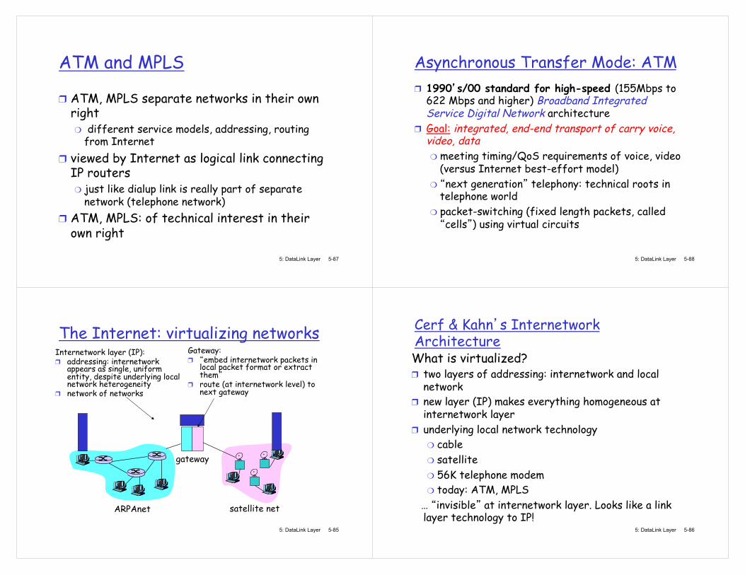
The Internet: virtualizing networks
ARPAnet satellite net
gateway
Internetwork layer (IP): addressing: internetwork appears as single, uniform entity, despite underlying local network heterogeneity network of networks
Gateway: embed internetwork packets in
local packet format or extract them route (at internetwork level) to next gateway
5: DataLink Layer 5-86
Cerf & Kahn s Internetwork Architecture What is virtualized?
two layers of addressing: internetwork and local network new layer (IP) makes everything homogeneous at internetwork layer underlying local network technology
cable satellite 56K telephone modem today: ATM, MPLS
�… invisible at internetwork layer. Looks like a link layer technology to IP!
5: DataLink Layer 5-87
ATM and MPLS
ATM, MPLS separate networks in their own right
different service models, addressing, routing from Internet
viewed by Internet as logical link connecting IP routers
just like dialup link is really part of separate network (telephone network)
ATM, MPLS: of technical interest in their own right
5: DataLink Layer 5-88
Asynchronous Transfer Mode: ATM 1990 s/00 standard for high-speed (155Mbps to 622 Mbps and higher) Broadband Integrated Service Digital Network architecture Goal: integrated, end-end transport of carry voice, video, data
meeting timing/QoS requirements of voice, video (versus Internet best-effort model) next generation telephony: technical roots in
telephone world packet-switching (fixed length packets, called cells ) using virtual circuits

5: DataLink Layer 5-89
Multiprotocol label switching (MPLS)
initial goal: speed up IP forwarding by using fixed length label (instead of IP address) to do forwarding
borrowing ideas from Virtual Circuit (VC) approach but IP datagram still keeps IP address!
PPP or Ethernet header
IP header remainder of link-layer frame MPLS header
label Exp S TTL
20 3 1 5 5: DataLink Layer 5-90
MPLS capable routers
a.k.a. label-switched router forwards packets to outgoing interface based only on label value (don t inspect IP address)
MPLS forwarding table distinct from IP forwarding tables
signaling protocol needed to set up forwarding RSVP-TE forwarding possible along paths that IP alone would not allow (e.g., source-specific routing) !! use MPLS for traffic engineering
must co-exist with IP-only routers
5: DataLink Layer 5-91
R1 R2
D
R3 R4 R5
0
1 0 0
A
R6
in out out label label dest interface
6 - A 0
in out out label label dest interface
10 6 A 1 12 9 D 0
in out out label label dest interface
10 A 0 12 D 0
1
in out out label label dest interface
8 6 A 0
0
8 A 1
MPLS forwarding tables
5: DataLink Layer 5-92
Link Layer
5.1 Introduction and services 5.2 Error detection and correction 5.3Multiple access protocols 5.4 Link-Layer Addressing 5.5 Ethernet
5.6 Link-layer switches 5.7 PPP 5.8 Link virtualization: MPLS 5.9 A day in the life of a web request
5: DataLink Layer 5-93
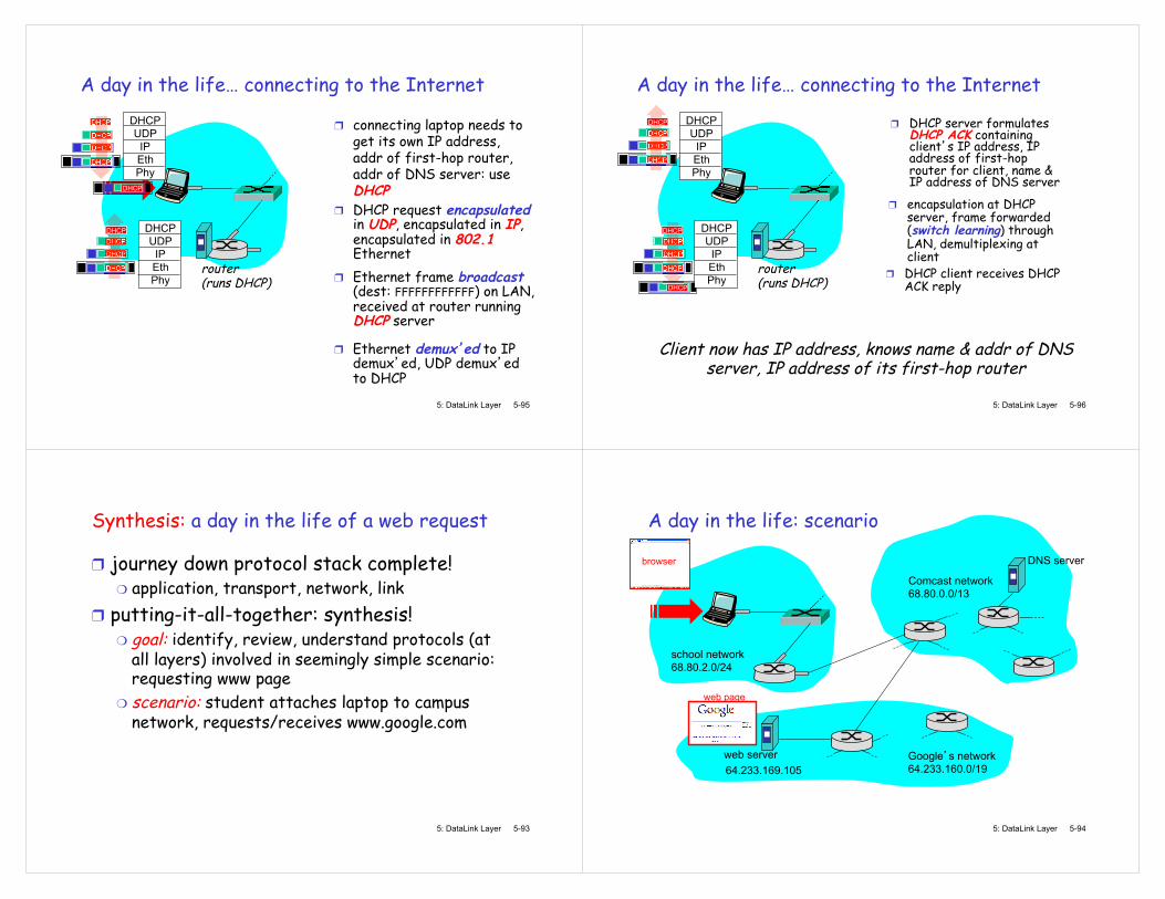
Synthesis: a day in the life of a web request
journey down protocol stack complete! application, transport, network, link
putting-it-all-together: synthesis! goal: identify, review, understand protocols (at all layers) involved in seemingly simple scenario: requesting www page scenario: student attaches laptop to campus network, requests/receives www.google.com
5: DataLink Layer 5-94
A day in the life: scenario
Comcast network 68.80.0.0/13
Google s network 64.233.160.0/19 64.233.169.105
web server
DNS server
school network 68.80.2.0/24
browser
web page
5: DataLink Layer 5-95
A day in the life�… connecting to the Internet
connecting laptop needs to get its own IP address, addr of first-hop router, addr of DNS server: use DHCP
router (runs DHCP)
DHCP UDP
IP Eth Phy
DHCP
DHCP
DHCP
DHCP
DHCP
DHCP UDP
IP Eth Phy
DHCP
DHCP
DHCP
DHCP DHCP
DHCP request encapsulated in UDP, encapsulated in IP, encapsulated in 802.1 Ethernet
Ethernet frame broadcast (dest: FFFFFFFFFFFF) on LAN, received at router running DHCP server
Ethernet demux ed to IP demux ed, UDP demux ed to DHCP
5: DataLink Layer 5-96
A day in the life�… connecting to the Internet
DHCP server formulates DHCP ACK containing client s IP address, IP address of first-hop router for client, name & IP address of DNS server
router (runs DHCP)
DHCP UDP
IP Eth Phy
DHCP
DHCP
DHCP
DHCP
DHCP UDP
IP Eth Phy
DHCP
DHCP
DHCP
DHCP
DHCP
encapsulation at DHCP server, frame forwarded (switch learning) through LAN, demultiplexing at client
Client now has IP address, knows name & addr of DNS server, IP address of its first-hop router
DHCP client receives DHCP ACK reply
5: DataLink Layer 5-97
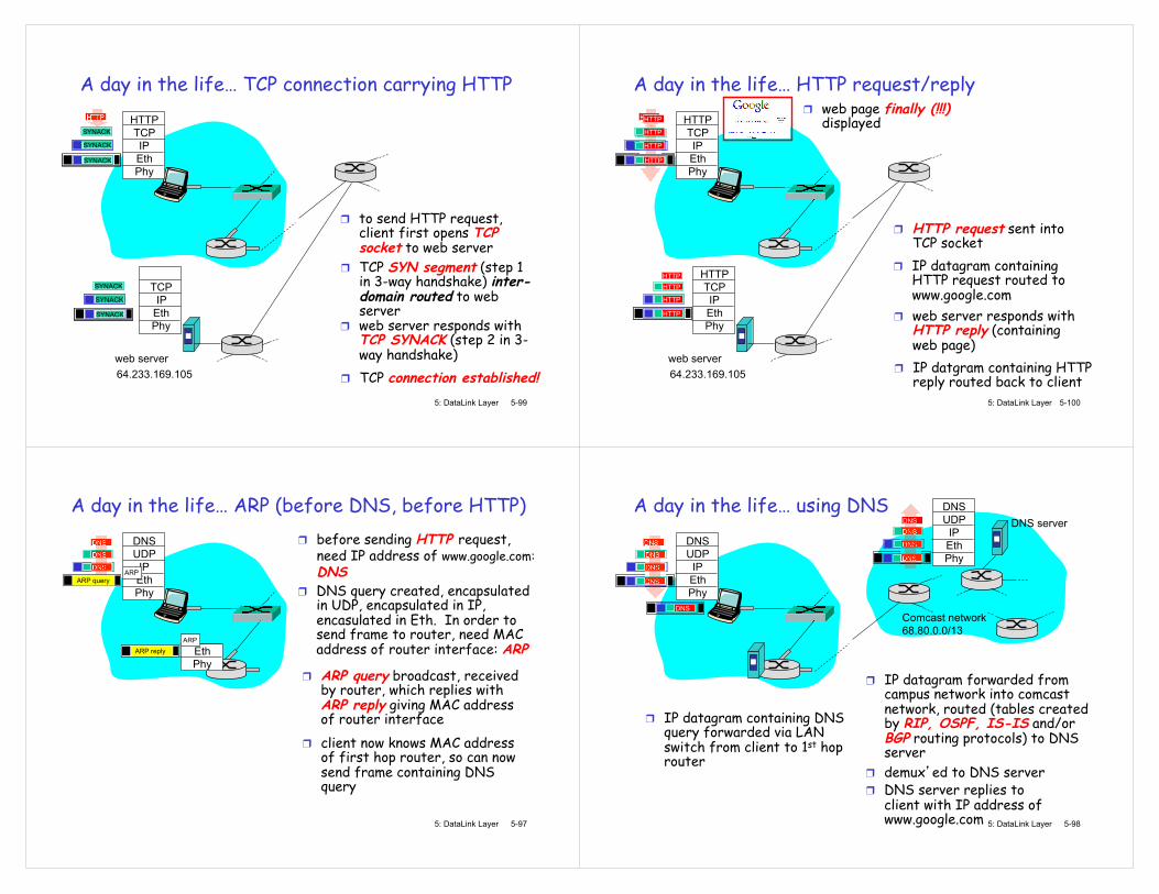
A day in the life�… ARP (before DNS, before HTTP) before sending HTTP request, need IP address of www.google.com: DNS
DNS UDP
IP Eth Phy
DNS
DNS
DNS
DNS query created, encapsulated in UDP, encapsulated in IP, encasulated in Eth. In order to send frame to router, need MAC address of router interface: ARP
ARP query broadcast, received by router, which replies with ARP reply giving MAC address of router interface client now knows MAC address of first hop router, so can now send frame containing DNS query
ARP query
Eth Phy
ARP
ARP
ARP reply
5: DataLink Layer 5-98
A day in the life�… using DNS DNS UDP
IP Eth Phy
DNS
DNS
DNS
DNS
DNS
IP datagram containing DNS query forwarded via LAN switch from client to 1st hop router
IP datagram forwarded from campus network into comcast network, routed (tables created by RIP, OSPF, IS-IS and/or BGP routing protocols) to DNS server demux ed to DNS server DNS server replies to client with IP address of www.google.com
Comcast network 68.80.0.0/13
DNS server
DNS UDP
IP Eth Phy
DNS
DNS
DNS
DNS
5: DataLink Layer 5-99
A day in the life�… TCP connection carrying HTTP HTTP TCP IP Eth Phy
HTTP
to send HTTP request, client first opens TCP socket to web server
TCP SYN segment (step 1 in 3-way handshake) inter-domain routed to web server
TCP connection established! 64.233.169.105 web server
SYN
SYN
SYN
SYN
TCP
IP Eth Phy
SYN
SYN
SYN
SYNACK
SYNACK
SYNACK
SYNACK
SYNACK
SYNACK
SYNACK
web server responds with TCP SYNACK (step 2 in 3-way handshake)
5: DataLink Layer 5-100
A day in the life�… HTTP request/reply HTTP TCP IP Eth Phy
HTTP
HTTP request sent into TCP socket IP datagram containing HTTP request routed to www.google.com
IP datgram containing HTTP reply routed back to client 64.233.169.105
web server
HTTP TCP IP Eth Phy
web server responds with HTTP reply (containing web page)
HTTP
HTTP
HTTP HTTP
HTTP
HTTP
HTTP
HTTP
HTTP
HTTP
HTTP
HTTP
HTTP
web page finally (!!!) displayed

5: DataLink Layer 5-101
Chapter 5: Summary principles behind data link layer services:
error detection, correction sharing a broadcast channel: multiple access link layer addressing
instantiation and implementation of various link layer technologies
Ethernet switched LANS, VLANs PPP virtualized networks as a link layer: MPLS
synthesis: a day in the life of a web request
5: DataLink Layer 5-102
Chapter 5: let s take a breath journey down protocol stack complete (except PHY) solid understanding of networking principles, practice �….. could stop here �…. but lots of interesting topics!
wireless multimedia security network management