Chapter 5 Data Link Layer - ERNETisg/NETWORKS/SLIDES/Ethernet-supp.pdf · Chapter 5 Data Link Layer...
143
Chapter 5 Data Link Layer 5: DataLink Layer 5a-1 Computer Networking: A Top Down Approach Featuring the Internet, 2 nd edition. Jim Kurose, Keith Ross Addison-Wesley, July 2002. A note on the use of these ppt slides: We’re making these slides freely available to all (faculty, students, readers). They’re in PowerPoint form so you can add, modify, and delete slides (including this one) and slide content to suit your needs. They obviously represent a lot of work on our part. In return for use, we only ask the following: If you use these slides (e.g., in a class) in substantially unaltered form, that you mention their source (after all, we’d like people to use our book!) If you post any slides in substantially unaltered form on a www site, that you note that they are adapted from (or perhaps identical to) our slides, and note our copyright of this material. Thanks and enjoy! JFK/KWR All material copyright 1996-2002 J.F Kurose and K.W. Ross, All Rights Reserved
Transcript of Chapter 5 Data Link Layer - ERNETisg/NETWORKS/SLIDES/Ethernet-supp.pdf · Chapter 5 Data Link Layer...
Chapter 5Data Link Layer
5: DataLink Layer 5a-1
Computer Networking: A Top Down Approach Featuring the Internet, 2nd edition. Jim Kurose, Keith RossAddison-Wesley, July 2002.
A note on the use of these ppt slides:We’re making these slides freely available to all (faculty, students, readers).
They’re in PowerPoint form so you can add, modify, and delete slides
(including this one) and slide content to suit your needs. They obviously
represent a lot of work on our part. In return for use, we only ask the
following:
� If you use these slides (e.g., in a class) in substantially unaltered form,
that you mention their source (after all, we’d like people to use our book!)
� If you post any slides in substantially unaltered form on a www site, that
you note that they are adapted from (or perhaps identical to) our slides, and
note our copyright of this material.
Thanks and enjoy! JFK/KWR
All material copyright 1996-2002
J.F Kurose and K.W. Ross, All Rights Reserved
Chapter 5: The Data Link Layer
Our goals:r understand principles behind data link layer services:
m error detection, correction
m sharing a broadcast channel: multiple access
link layer addressing
5: DataLink Layer 5a-2
m link layer addressing
m reliable data transfer, flow control: done!
r instantiation and implementation of various link layer technologies

Chapter 5 outline
r 5.1 Introduction and services
r 5.2 Error detection and correction
r 5.3Multiple access
r 5.6 Hubs, bridges, and switches
r 5.7 Wireless links and LANs
r 5.8 PPP
5: DataLink Layer 5a-3
r 5.3Multiple access protocols
r 5.4 LAN addresses and ARP
r 5.5 Ethernet
r 5.8 PPP
r 5.9 ATM
r 5.10 Frame Relay
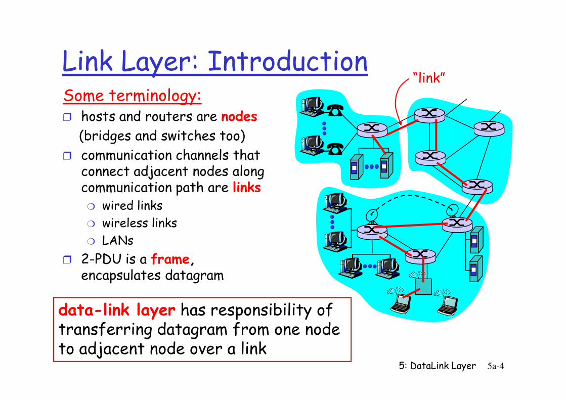
Link Layer: IntroductionSome terminology:r hosts and routers are nodes
(bridges and switches too)
r communication channels that connect adjacent nodes along communication path are links
wired links
“link”
5: DataLink Layer 5a-4
m wired links
m wireless links
m LANs
r 2-PDU is a frame,encapsulates datagram
data-link layer has responsibility of transferring datagram from one node to adjacent node over a link
Link layer: context
r Datagram transferred by different link protocols over different links:
m e.g., Ethernet on first link, frame relay on intermediate links, 802.11 on last link
transportation analogyr trip from Princeton to
Lausanne
m limo: Princeton to JFK
m plane: JFK to Geneva
m train: Geneva to Lausanne
tourist = datagram
5: DataLink Layer 5a-5
on last link
r Each link protocol provides different services
m e.g., may or may not provide rdt over link
r tourist = datagram
r transport segment = communication link
r transportation mode = link layer protocol
r travel agent = routing algorithm
Link Layer Services
r Framing, link access:m encapsulate datagram into frame, adding header, trailer
m channel access if shared medium
m ‘physical addresses’ used in frame headers to identify source, dest
• different from IP address!
5: DataLink Layer 5a-6
• different from IP address!
r Reliable delivery between adjacent nodesm we learned how to do this already (chapter 3)!
m seldom used on low bit error link (fiber, some twisted pair)
m wireless links: high error rates
• Q: why both link-level and end-end reliability?
Link Layer Services (more)
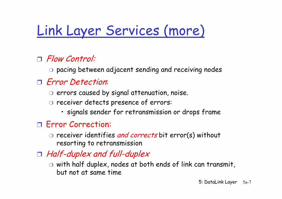
r Flow Control:m pacing between adjacent sending and receiving nodes
r Error Detection:m errors caused by signal attenuation, noise.
receiver detects presence of errors:
5: DataLink Layer 5a-7
m receiver detects presence of errors:
• signals sender for retransmission or drops frame
r Error Correction:m receiver identifies and corrects bit error(s) without resorting to retransmission
r Half-duplex and full-duplexm with half duplex, nodes at both ends of link can transmit, but not at same time
Adaptors Communicating
r link layer implemented in r receiving side
sendingnode
frame
rcvingnode
datagram
frame
adapter adapter
link layer protocol
5: DataLink Layer 5a-8
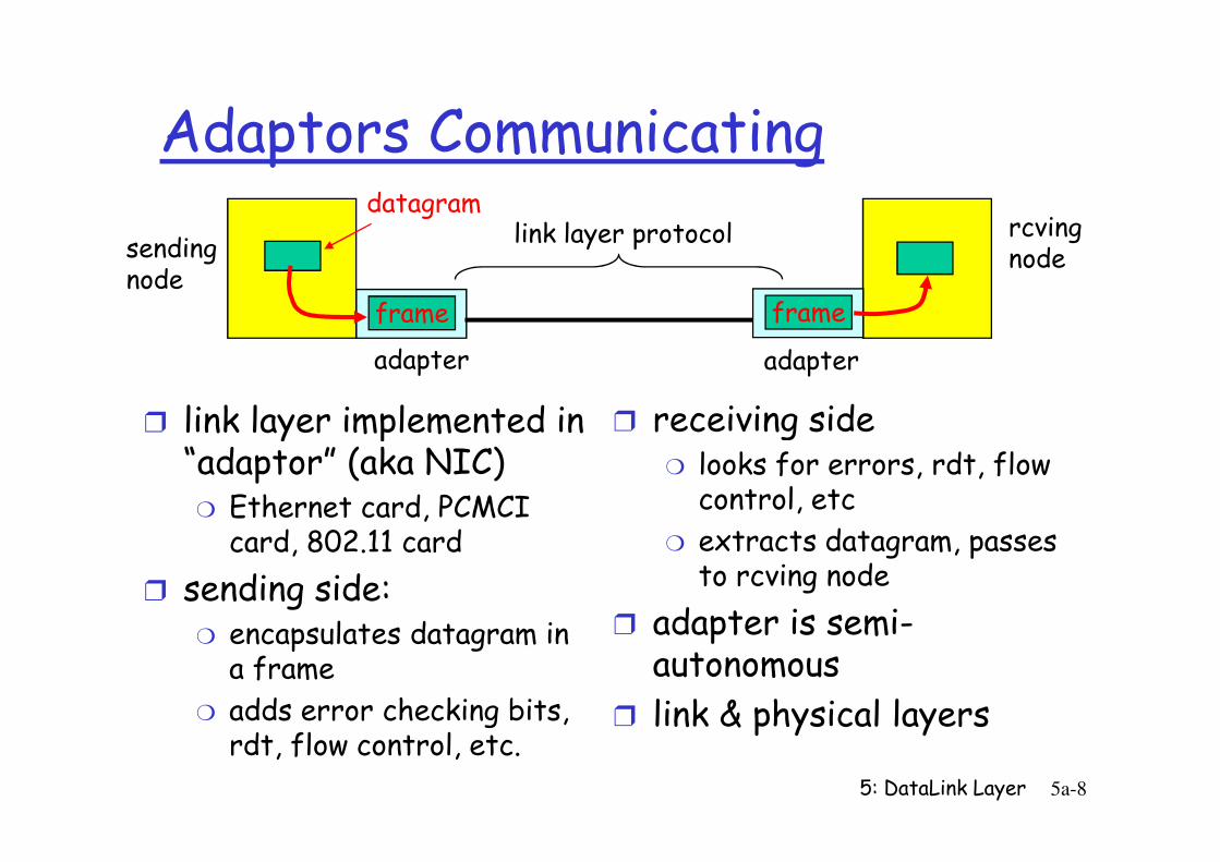
r link layer implemented in “adaptor” (aka NIC)
m Ethernet card, PCMCI card, 802.11 card
r sending side:m encapsulates datagram in a frame
m adds error checking bits, rdt, flow control, etc.
r receiving sidem looks for errors, rdt, flow control, etc
m extracts datagram, passes to rcving node
r adapter is semi-autonomous
r link & physical layers
Chapter 5 outline
r 5.1 Introduction and services
r 5.2 Error detection and correction
r 5.3Multiple access
r 5.6 Hubs, bridges, and switches
r 5.7 Wireless links and LANs
r 5.8 PPP
5: DataLink Layer 5a-9
r 5.3Multiple access protocols
r 5.4 LAN addresses and ARP
r 5.5 Ethernet
r 5.8 PPP
r 5.9 ATM
r 5.10 Frame Relay
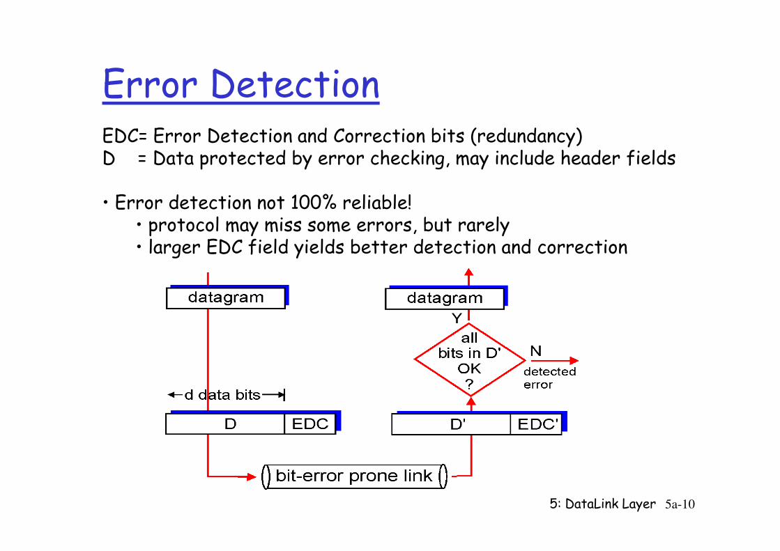
Error DetectionEDC= Error Detection and Correction bits (redundancy)D = Data protected by error checking, may include header fields
• Error detection not 100% reliable!• protocol may miss some errors, but rarely• larger EDC field yields better detection and correction
5: DataLink Layer 5a-10
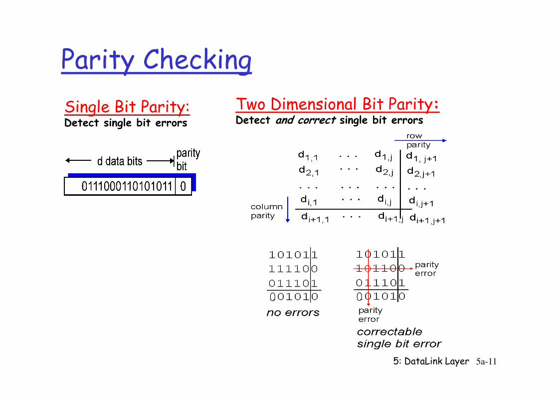
Parity Checking
Single Bit Parity:Detect single bit errors
Two Dimensional Bit Parity:Detect and correct single bit errors
5: DataLink Layer 5a-11
0 0
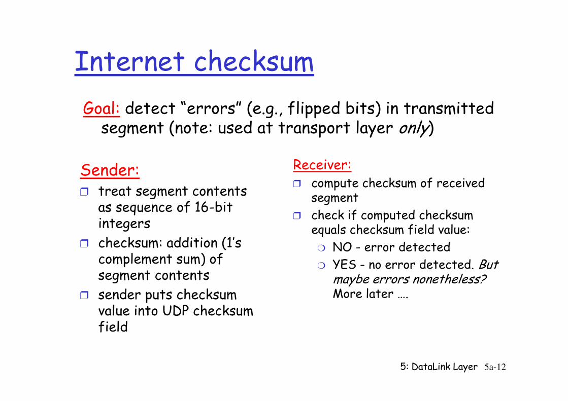
Internet checksum
Sender:r treat segment contents
as sequence of 16-bit
Receiver:r compute checksum of received
segment
Goal: detect “errors” (e.g., flipped bits) in transmitted segment (note: used at transport layer only)
5: DataLink Layer 5a-12
as sequence of 16-bit integers
r checksum: addition (1’s complement sum) of segment contents
r sender puts checksum value into UDP checksum field
segment
r check if computed checksum equals checksum field value:
m NO - error detected
m YES - no error detected. But maybe errors nonetheless?More later ….
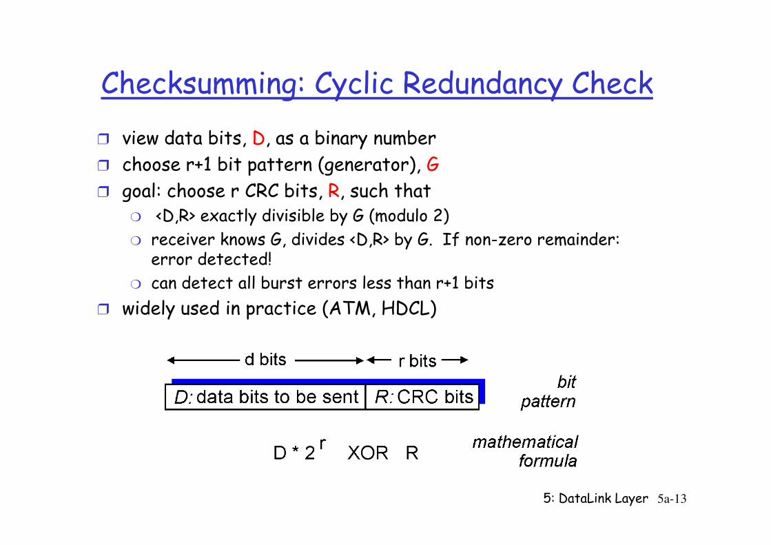
Checksumming: Cyclic Redundancy Check
r view data bits, D, as a binary number
r choose r+1 bit pattern (generator), G
r goal: choose r CRC bits, R, such thatm <D,R> exactly divisible by G (modulo 2)
m receiver knows G, divides <D,R> by G. If non-zero remainder: error detected!
can detect all burst errors less than r+1 bits
5: DataLink Layer 5a-13
m can detect all burst errors less than r+1 bits
r widely used in practice (ATM, HDCL)
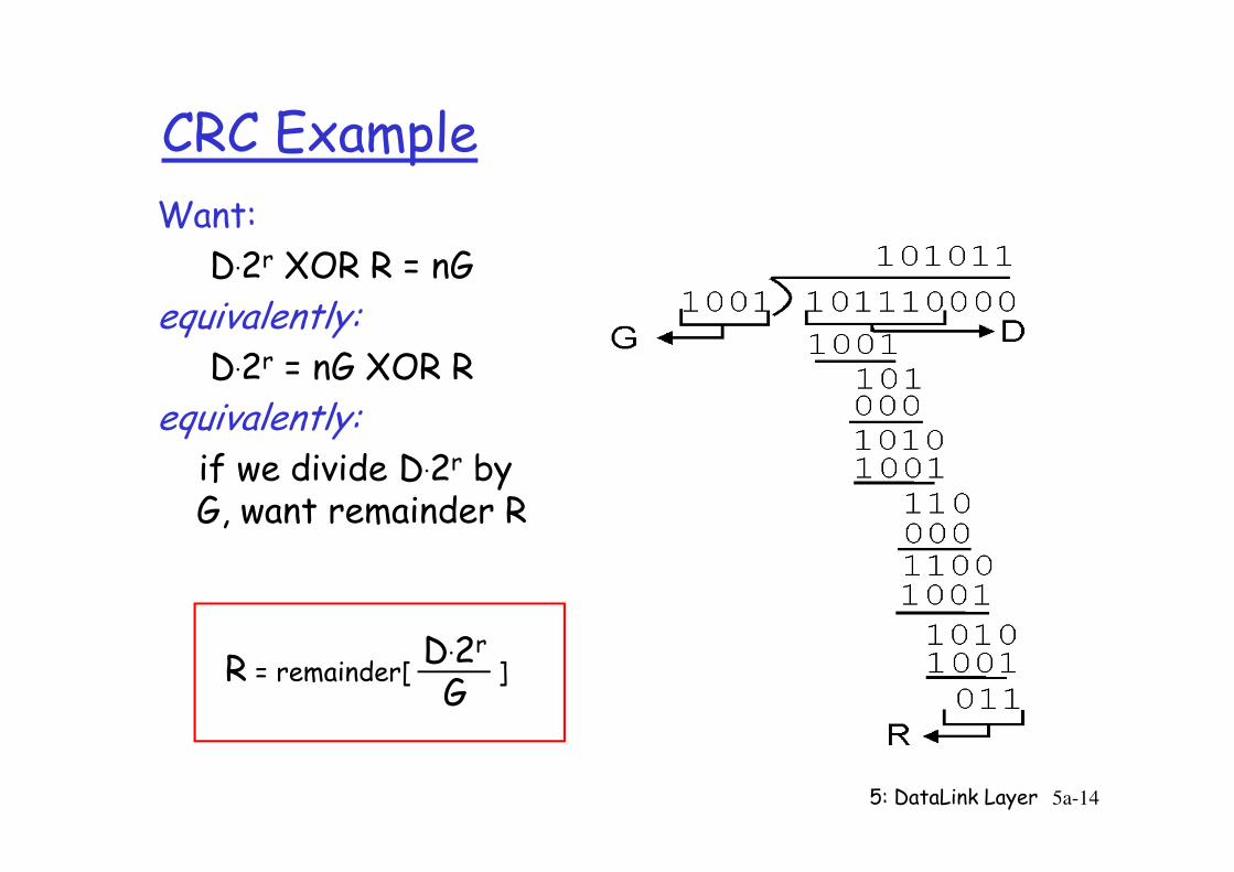
CRC Example
Want:
D.2r XOR R = nG
equivalently:D.2r = nG XOR R
equivalently:
5: DataLink Layer 5a-14
equivalently:if we divide D.2r by G, want remainder R
R = remainder[ ]D.2r
G
Chapter 5 outline
r 5.1 Introduction and services
r 5.2 Error detection and correction
r 5.3Multiple access
r 5.6 Hubs, bridges, and switches
r 5.7 Wireless links and LANs
r 5.8 PPP
5: DataLink Layer 5a-15
r 5.3Multiple access protocols
r 5.4 LAN addresses and ARP
r 5.5 Ethernet
r 5.8 PPP
r 5.9 ATM
r 5.10 Frame Relay
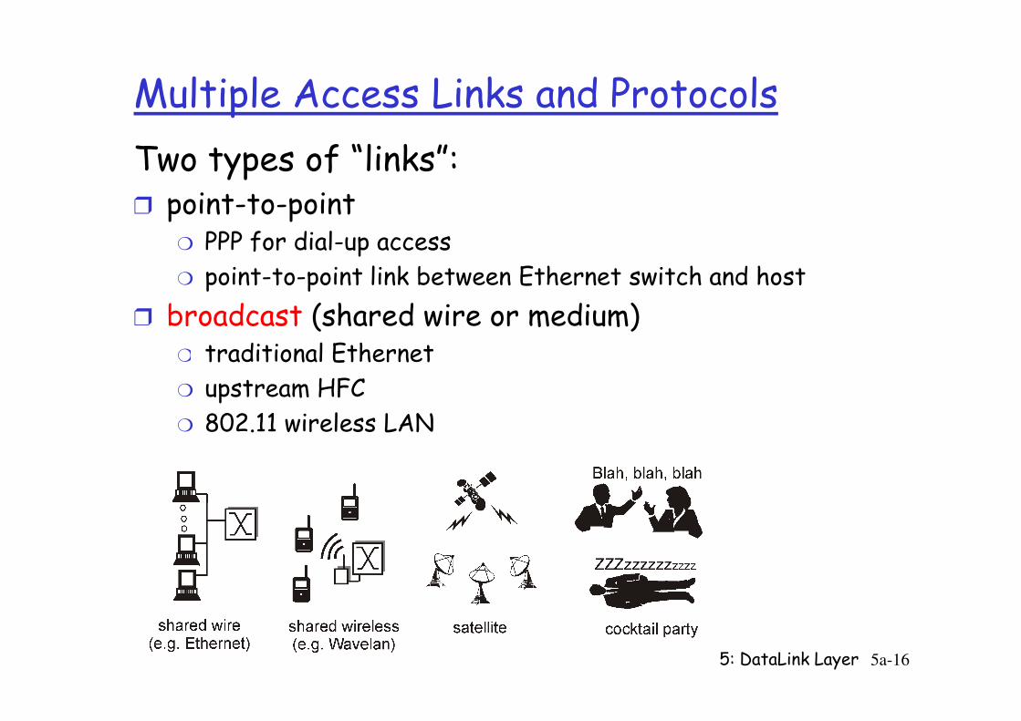
Multiple Access Links and Protocols
Two types of “links”:r point-to-point
m PPP for dial-up access
m point-to-point link between Ethernet switch and host
r broadcast (shared wire or medium)m traditional Ethernet
5: DataLink Layer 5a-16
m traditional Ethernet
m upstream HFC
m 802.11 wireless LAN
Multiple Access protocols
r single shared broadcast channel
r two or more simultaneous transmissions by nodes: interference
m only one node can send successfully at a time
multiple access protocol
5: DataLink Layer 5a-17
r distributed algorithm that determines how nodes share channel, i.e., determine when node can transmit
r communication about channel sharing must use channel itself!
r what to look for in multiple access protocols:
Ideal Mulitple Access Protocol
Broadcast channel of rate R bps
1. When one node wants to transmit, it can send at rate R.
2. When M nodes want to transmit, each can send at average rate R/M
5: DataLink Layer 5a-18
average rate R/M
3. Fully decentralized:m no special node to coordinate transmissions
m no synchronization of clocks, slots
4. Simple
MAC Protocols: a taxonomy
Three broad classes:
r Channel Partitioningm divide channel into smaller “pieces” (time slots, frequency, code)
m allocate piece to node for exclusive use
r Random Access
5: DataLink Layer 5a-19
r Random Accessm channel not divided, allow collisions
m “recover” from collisions
r “Taking turns”m tightly coordinate shared access to avoid collisions
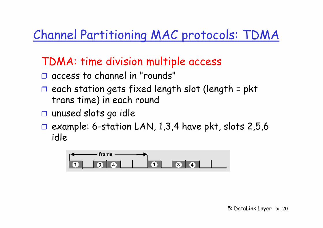
Channel Partitioning MAC protocols: TDMA
TDMA: time division multiple accessr access to channel in "rounds"
r each station gets fixed length slot (length = pkt trans time) in each round
r unused slots go idle
5: DataLink Layer 5a-20
r unused slots go idle
r example: 6-station LAN, 1,3,4 have pkt, slots 2,5,6 idle
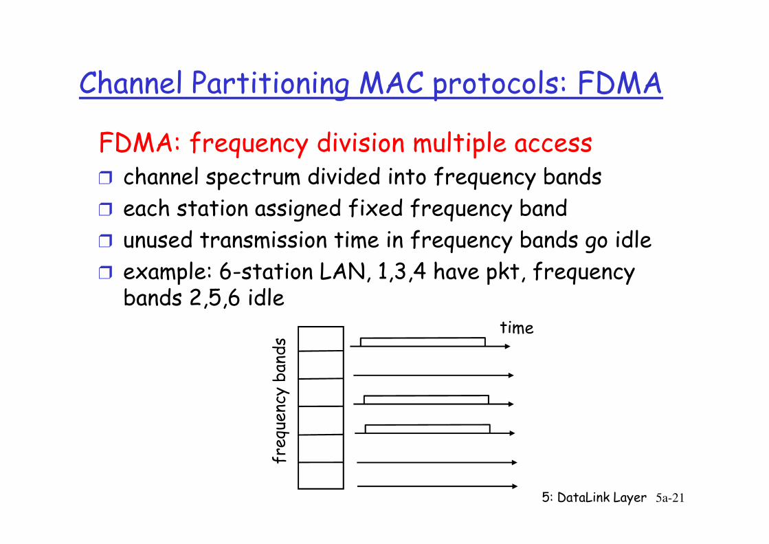
Channel Partitioning MAC protocols: FDMA
FDMA: frequency division multiple accessr channel spectrum divided into frequency bands
r each station assigned fixed frequency band
r unused transmission time in frequency bands go idle
r example: 6-station LAN, 1,3,4 have pkt, frequency
5: DataLink Layer 5a-21
r example: 6-station LAN, 1,3,4 have pkt, frequency bands 2,5,6 idle
frequency bands
Channel Partitioning (CDMA)
CDMA (Code Division Multiple Access)r unique “code” assigned to each user; i.e., code set partitioning
r used mostly in wireless broadcast channels (cellular, satellite, etc)
r all users share same frequency, but each user has own
5: DataLink Layer 5a-22
r all users share same frequency, but each user has own “chipping” sequence (i.e., code) to encode data
r encoded signal = (original data) X (chipping sequence)r decoding: inner-product of encoded signal and chipping
sequence
r allows multiple users to “coexist” and transmit simultaneously with minimal interference (if codes are “orthogonal”)
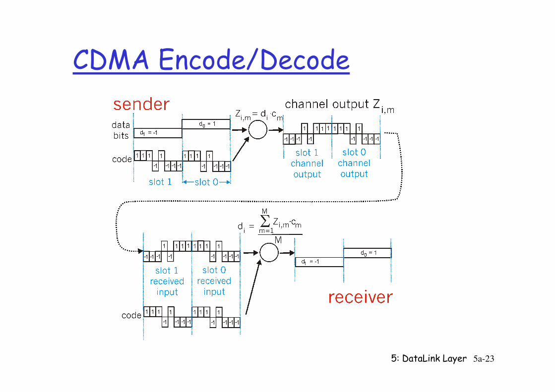
CDMA Encode/Decode
5: DataLink Layer 5a-23
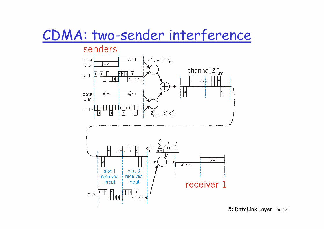
CDMA: two-sender interference
5: DataLink Layer 5a-24
Random Access Protocols
r When node has packet to sendm transmit at full channel data rate R.
m no a priori coordination among nodes
r two or more transmitting nodes -> “collision”,
r random access MAC protocol specifies:
5: DataLink Layer 5a-25
r random access MAC protocol specifies: m how to detect collisions
m how to recover from collisions (e.g., via delayed retransmissions)
r Examples of random access MAC protocols:m slotted ALOHA
m ALOHA
m CSMA, CSMA/CD, CSMA/CA
Slotted ALOHA
Assumptions
r all frames same size
r time is divided into equal size slots, time to transmit 1 frame
Operation
r when node obtains fresh frame, it transmits in next slot
r no collision, node can send
5: DataLink Layer 5a-26
transmit 1 frame
r nodes start to transmit frames only at beginning of slots
r nodes are synchronized
r if 2 or more nodes transmit in slot, all nodes detect collision
r no collision, node can send new frame in next slot
r if collision, node retransmits frame in each subsequent slot with prob. p until success
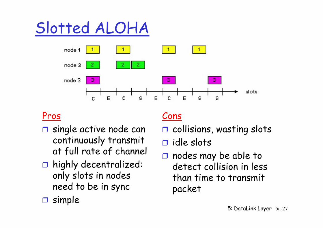
Slotted ALOHA
Pros Cons
5: DataLink Layer 5a-27
Pros
r single active node can continuously transmit at full rate of channel
r highly decentralized: only slots in nodes need to be in sync
r simple
Cons
r collisions, wasting slots
r idle slots
r nodes may be able to detect collision in less than time to transmit packet
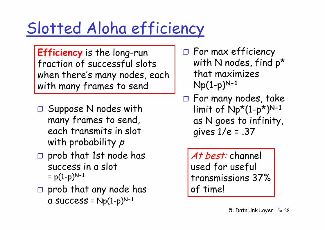
Slotted Aloha efficiency
r Suppose N nodes with many frames to send,
r For max efficiency with N nodes, find p* that maximizes Np(1-p)N-1
r For many nodes, take limit of Np*(1-p*)N-1
as N goes to infinity,
Efficiency is the long-run fraction of successful slots when there’s many nodes, each with many frames to send
5: DataLink Layer 5a-28
many frames to send, each transmits in slot with probability p
r prob that 1st node has success in a slot= p(1-p)N-1
r prob that any node has a success = Np(1-p)N-1
limit of Np*(1-p*)as N goes to infinity, gives 1/e = .37
At best: channelused for useful transmissions 37%of time!
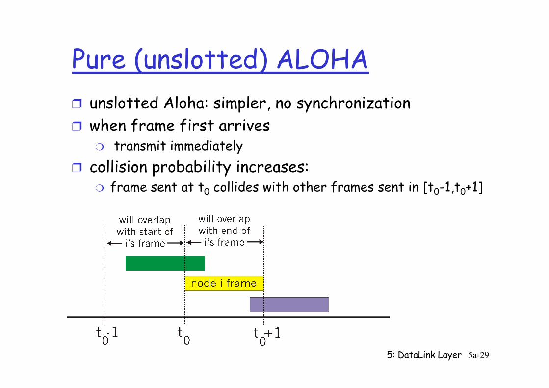
Pure (unslotted) ALOHA
r unslotted Aloha: simpler, no synchronization
r when frame first arrivesm transmit immediately
r collision probability increases:m frame sent at t0 collides with other frames sent in [t0-1,t0+1]
5: DataLink Layer 5a-29
frame sent at t0 collides with other frames sent in [t0-1,t0+1]
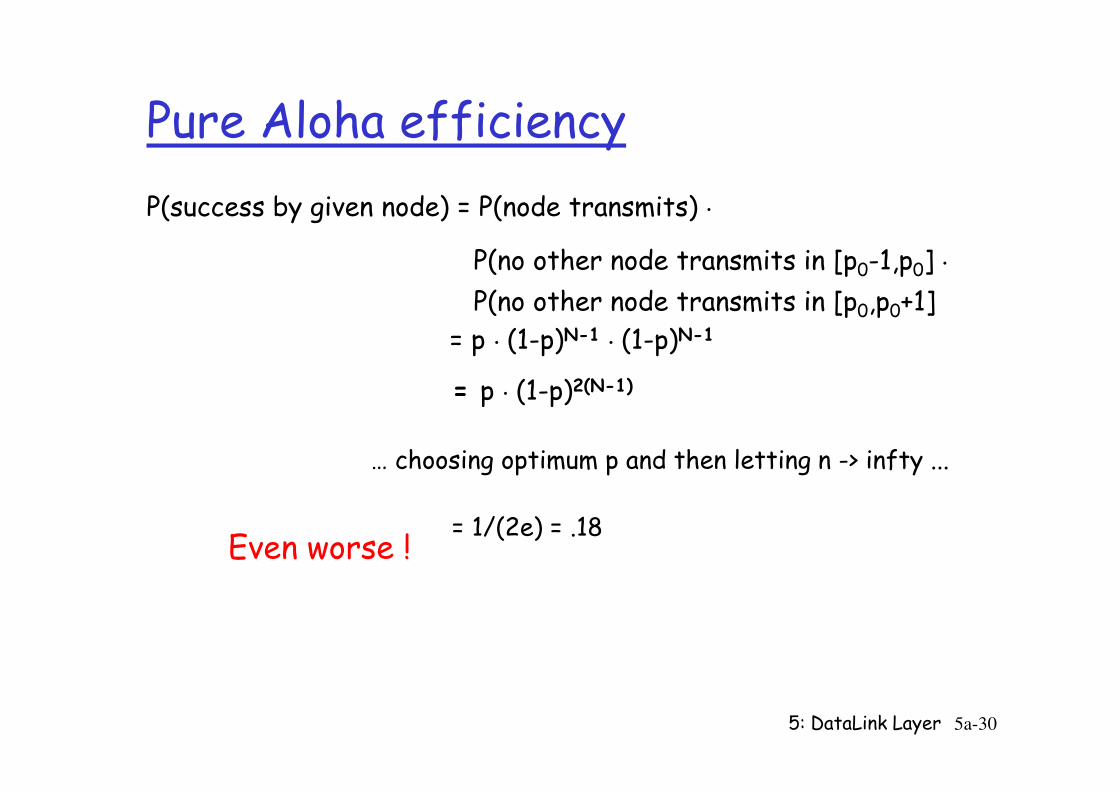
Pure Aloha efficiency
P(success by given node) = P(node transmits) .
P(no other node transmits in [p0-1,p0] .
P(no other node transmits in [p0,p0+1]
= p . (1-p)N-1 . (1-p)N-1
= p . (1-p)2(N-1)
5: DataLink Layer 5a-30
= p . (1-p)2(N-1)
… choosing optimum p and then letting n -> infty ...
= 1/(2e) = .18 Even worse !
CSMA (Carrier Sense Multiple Access)
CSMA: listen before transmit:
r If channel sensed idle: transmit entire frame
r If channel sensed busy, defer transmission
5: DataLink Layer 5a-31
r Human analogy: don’t interrupt others!
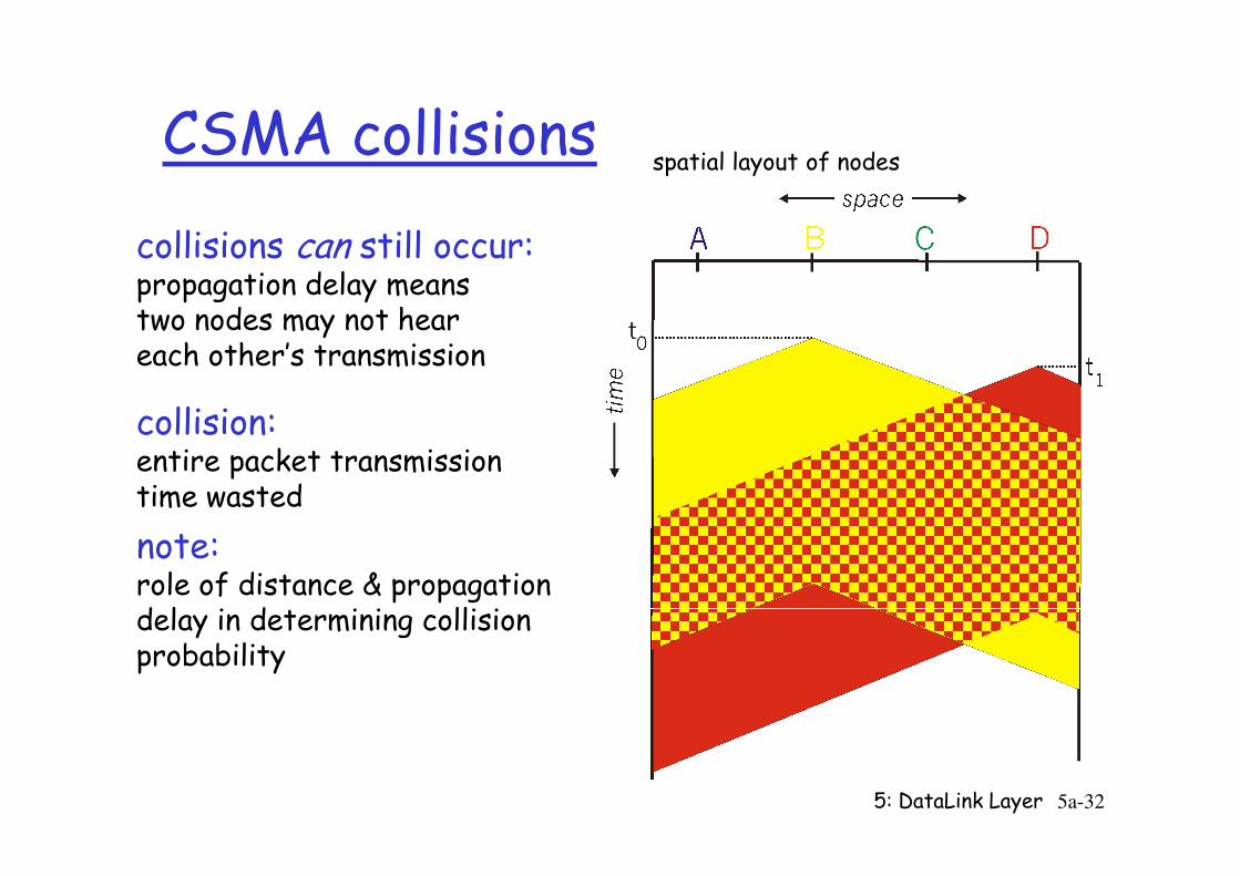
CSMA collisions
collisions can still occur:propagation delay means two nodes may not heareach other’s transmission
collision:
spatial layout of nodes
5: DataLink Layer 5a-32
collision:entire packet transmission time wasted
note:role of distance & propagation delay in determining collision probability
CSMA/CD (Collision Detection)
CSMA/CD: carrier sensing, deferral as in CSMAm collisions detected within short timem colliding transmissions aborted, reducing channel wastage
r collision detection:
5: DataLink Layer 5a-33
r collision detection:m easy in wired LANs: measure signal strengths, compare transmitted, received signals
m difficult in wireless LANs: receiver shut off while transmitting
r human analogy: the polite conversationalist
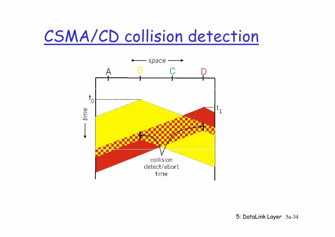
CSMA/CD collision detection
5: DataLink Layer 5a-34
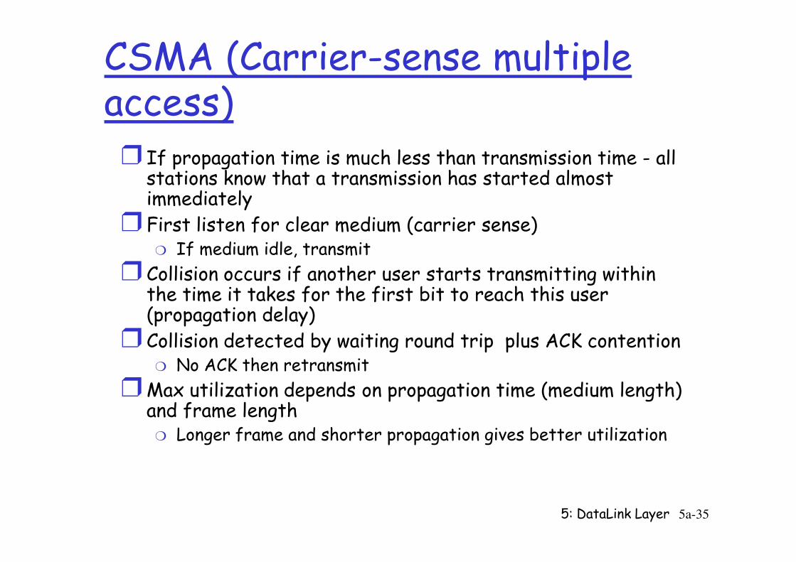
CSMA (Carrier-sense multiple access)
r If propagation time is much less than transmission time - all stations know that a transmission has started almost immediately
r First listen for clear medium (carrier sense)m If medium idle, transmit
r Collision occurs if another user starts transmitting within the time it takes for the first bit to reach this user
5: DataLink Layer 5a-35
r Collision occurs if another user starts transmitting within the time it takes for the first bit to reach this user (propagation delay)
r Collision detected by waiting round trip plus ACK contentionm No ACK then retransmit
rMax utilization depends on propagation time (medium length) and frame length
m Longer frame and shorter propagation gives better utilization
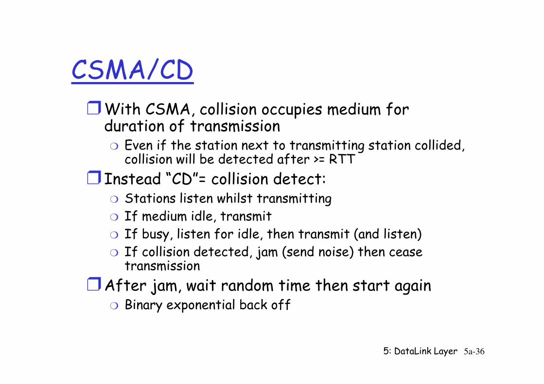
CSMA/CDrWith CSMA, collision occupies medium for duration of transmission
m Even if the station next to transmitting station collided, collision will be detected after >= RTT
r Instead “CD”= collision detect:Stations listen whilst transmitting
5: DataLink Layer 5a-36
m Stations listen whilst transmittingm If medium idle, transmitm If busy, listen for idle, then transmit (and listen)m If collision detected, jam (send noise) then cease transmission
rAfter jam, wait random time then start againm Binary exponential back off
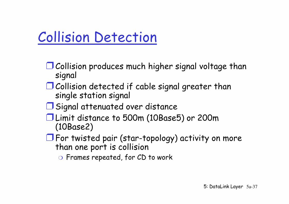
Collision Detection
rCollision produces much higher signal voltage than signal
rCollision detected if cable signal greater than single station signal
rSignal attenuated over distance
5: DataLink Layer 5a-37
rSignal attenuated over distancer Limit distance to 500m (10Base5) or 200m (10Base2)
rFor twisted pair (star-topology) activity on more than one port is collision
m Frames repeated, for CD to work
Why “Jam”?r Tanenbaum: “to make sure the sender does not miss the
collision” (48 bits)rHalsall: “Ensure that the collision is detected by all stations
involved”r Stallings: “Assure all staitons know that there has been a
collision”r
5: DataLink Layer 5a-38
collision”r Keshav: “Sequence of 512 bits to ensure that every active
station on the network knows that a collision happened and increments its backoff counter”; “to ensure that all colliding stations agree that a collision has happened”
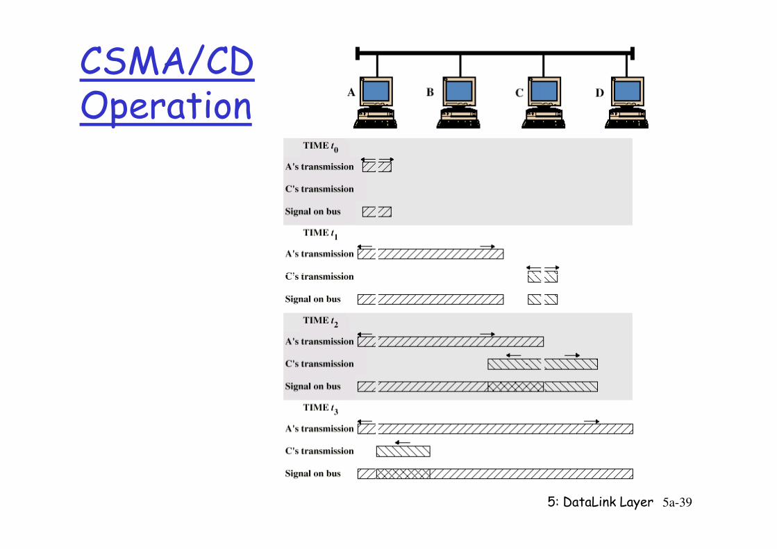
CSMA/CDOperation
5: DataLink Layer 5a-39
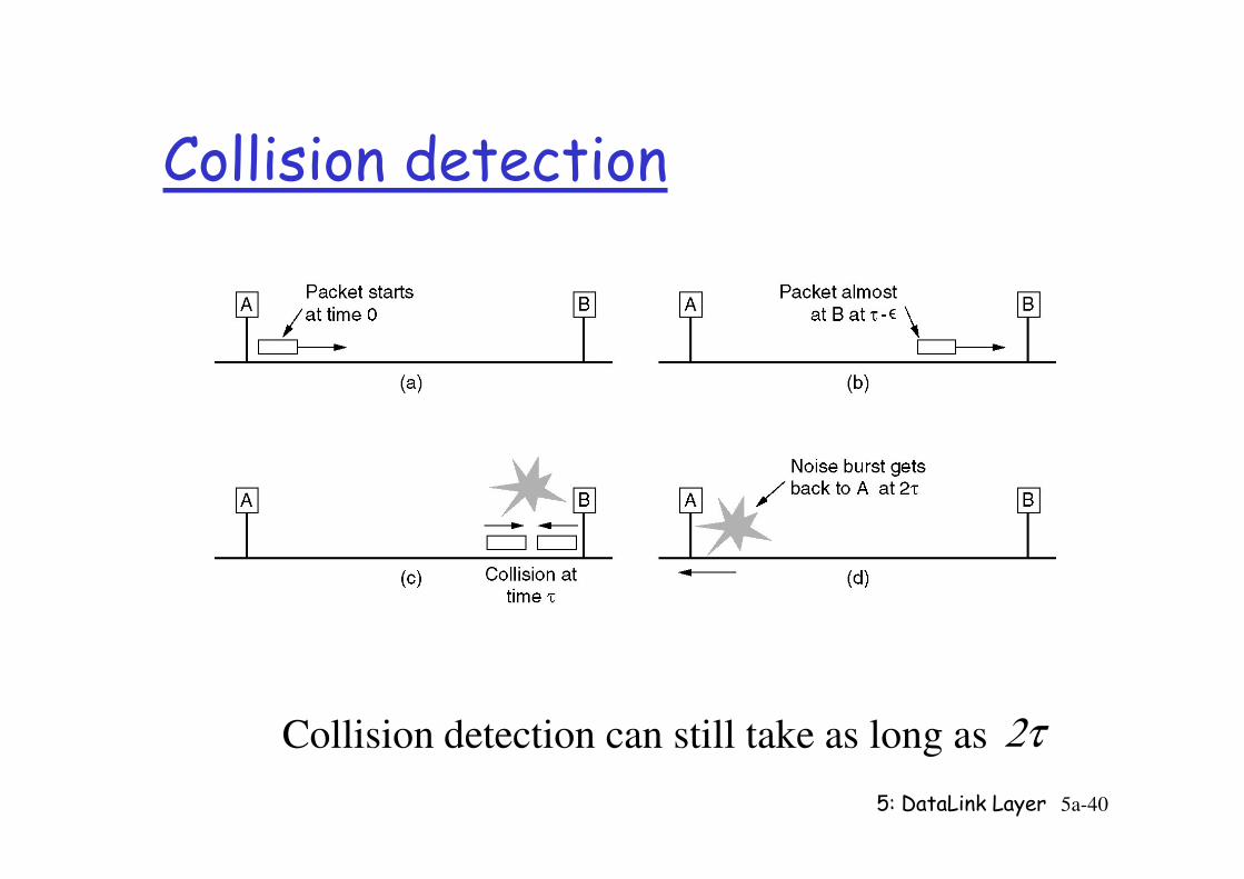
Collision detection
5: DataLink Layer 5a-40
Collision detection can still take as long as 2τ
Collision detection
rTransmitting stations may detect collisions almost immediately, and stop transmission
m Saves time and bandwidth
rWill improve upon just CSMA only if collision is detected during frame transmission
5: DataLink Layer 5a-41
detected during frame transmissionrThis is possible if frames are long enough (and prop. Delay is short enough) so that collision is detected while transmission
m Guideline used in IEEE 802.3m Frame transmission time >= 2*prop + delta
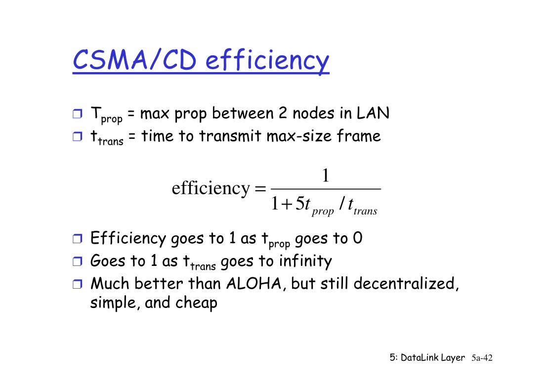
CSMA/CD efficiency
r Tprop = max prop between 2 nodes in LAN
r ttrans = time to transmit max-size frame
tt /51
1efficiency
+=
5: DataLink Layer 5a-42
r Efficiency goes to 1 as tprop goes to 0
r Goes to 1 as ttrans goes to infinity
r Much better than ALOHA, but still decentralized, simple, and cheap
transproptt /51
efficiency+
=
“Taking Turns” MAC protocols
channel partitioning MAC protocols:
m share channel efficiently and fairly at high load
m inefficient at low load: delay in channel access, 1/N bandwidth allocated even if only 1 active node!
5: DataLink Layer 5a-43
node!
Random access MAC protocols
m efficient at low load: single node can fully utilize channel
m high load: collision overhead
“taking turns” protocols
look for best of both worlds!
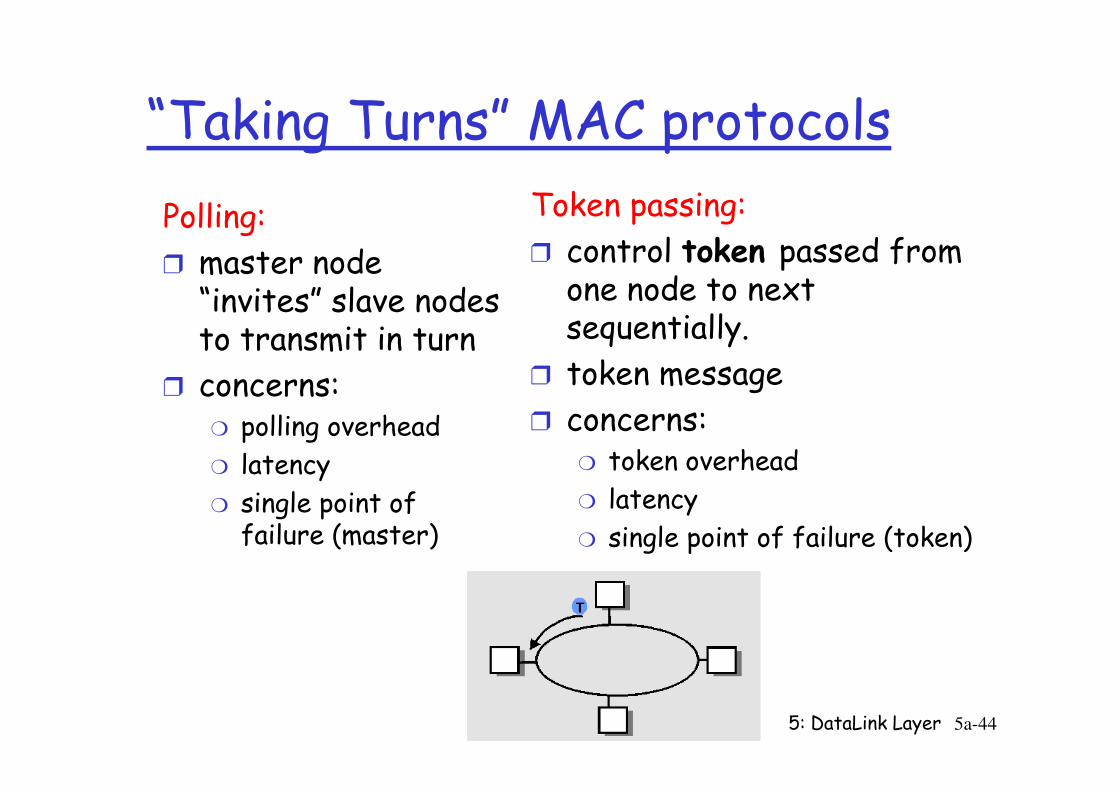
“Taking Turns” MAC protocols
Polling:
r master node “invites” slave nodes to transmit in turn
r concerns:
Token passing:
r control token passed from one node to next sequentially.
r token message
concerns:
5: DataLink Layer 5a-44
r concerns:m polling overhead
m latency
m single point of failure (master)
r concerns:m token overhead
m latency
m single point of failure (token)
Summary of MAC protocols
r What do you do with a shared media?m Channel Partitioning, by time, frequency or code
• Time Division,Code Division, Frequency Division
m Random partitioning (dynamic), • ALOHA, S-ALOHA, CSMA, CSMA/CD
5: DataLink Layer 5a-45
• ALOHA, S-ALOHA, CSMA, CSMA/CD
• carrier sensing: easy in some technologies (wire), hard in others (wireless)
• CSMA/CD used in Ethernet
m Taking Turns• polling from a central site, token passing
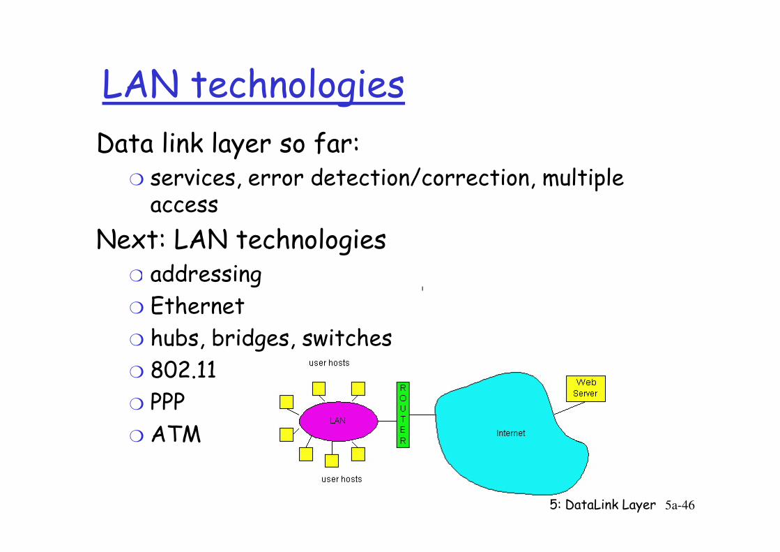
LAN technologies
Data link layer so far:m services, error detection/correction, multiple access
Next: LAN technologiesm addressing
5: DataLink Layer 5a-46
m addressing
m Ethernet
m hubs, bridges, switches
m 802.11
m PPP
m ATM
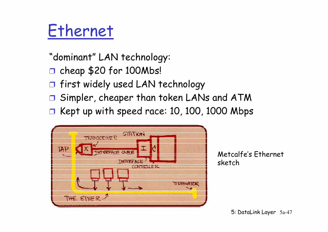
Ethernet
“dominant” LAN technology:
r cheap $20 for 100Mbs!
r first widely used LAN technology
r Simpler, cheaper than token LANs and ATM
r Kept up with speed race: 10, 100, 1000 Mbps
5: DataLink Layer 5a-47
Kept up with speed race: 10, 100, 1000 Mbps
Metcalfe’s Ethernetsketch
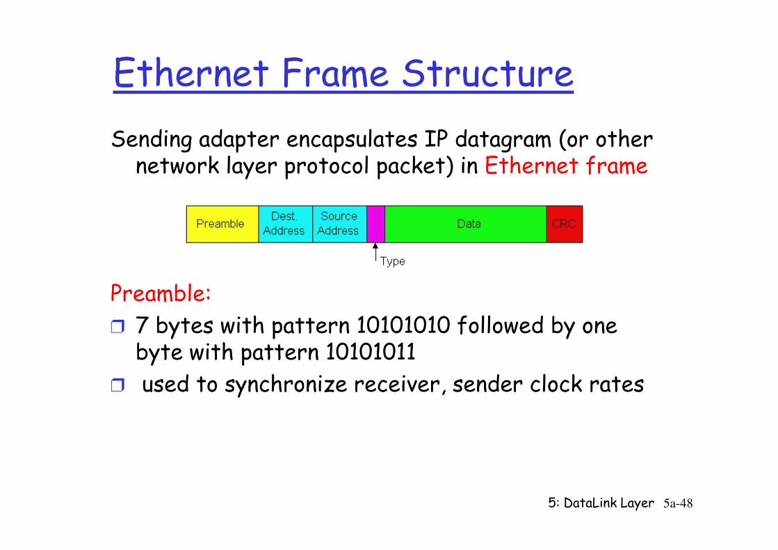
Ethernet Frame Structure
Sending adapter encapsulates IP datagram (or other network layer protocol packet) in Ethernet frame
5: DataLink Layer 5a-48
Preamble:
r 7 bytes with pattern 10101010 followed by one byte with pattern 10101011
r used to synchronize receiver, sender clock rates
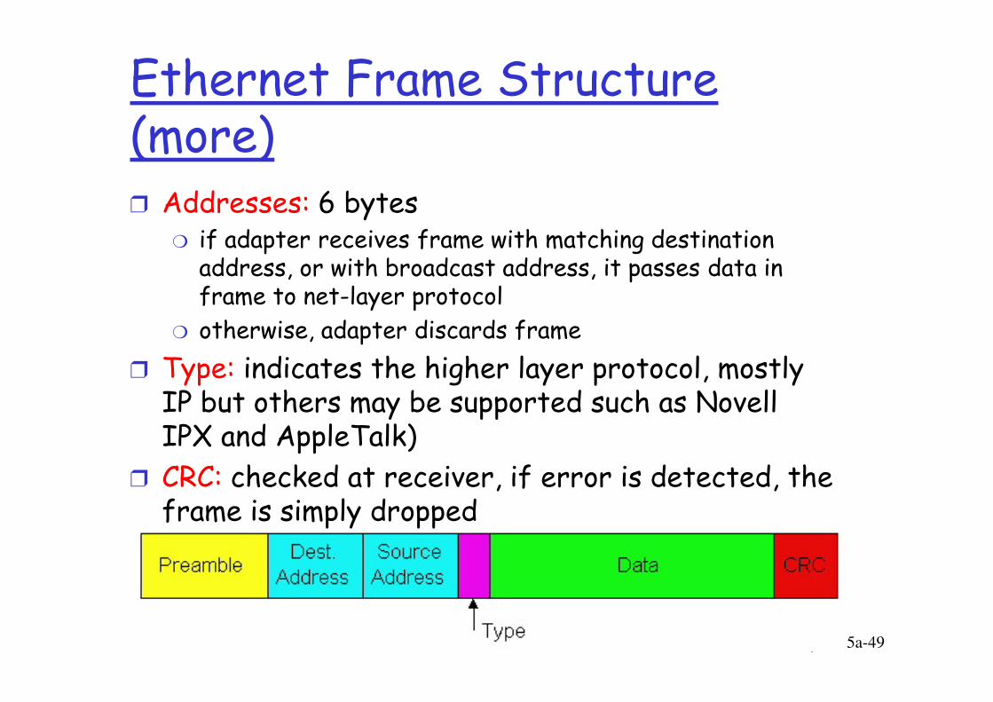
Ethernet Frame Structure (more)r Addresses: 6 bytes
m if adapter receives frame with matching destination address, or with broadcast address, it passes data in frame to net-layer protocol
m otherwise, adapter discards frame
Type: indicates the higher layer protocol, mostly
5: DataLink Layer 5a-49
r Type: indicates the higher layer protocol, mostly IP but others may be supported such as Novell IPX and AppleTalk)
r CRC: checked at receiver, if error is detected, the frame is simply dropped
Ethernet min frame length
rMin length needed for CD: for 2500m distance specification, RT prop delay is determined to be 50 µsec
m Frame transmission time >= 50 µsec
m At 10Mbps, bits transmitted in 50 µsec is 500 <= 512 =
5: DataLink Layer 5a-50
m At 10Mbps, bits transmitted in 50 µsec is 500 <= 512 = 64*8 bits = 64 bytes
rWhen transmission interrupted, “bits & pieces” of frames appear on the cable
m Min frame length is one “filter” for valid frames
forward
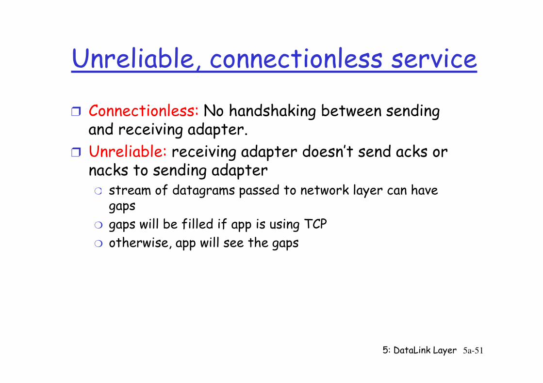
Unreliable, connectionless service
r Connectionless: No handshaking between sending and receiving adapter.
r Unreliable: receiving adapter doesn’t send acks or nacks to sending adapter
m stream of datagrams passed to network layer can have
5: DataLink Layer 5a-51
m stream of datagrams passed to network layer can have gaps
m gaps will be filled if app is using TCP
m otherwise, app will see the gaps
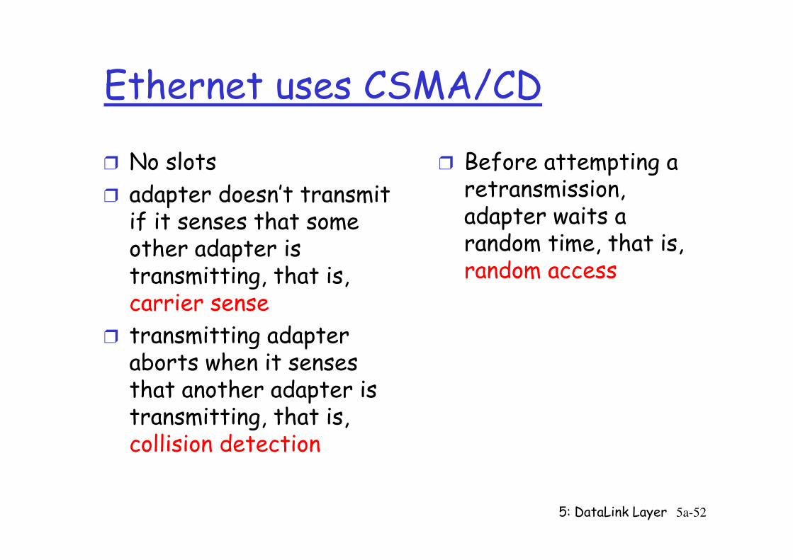
Ethernet uses CSMA/CD
r No slots
r adapter doesn’t transmit if it senses that some other adapter is transmitting, that is,
r Before attempting a retransmission, adapter waits a random time, that is, random access
5: DataLink Layer 5a-52
transmitting, that is, carrier sense
r transmitting adapter aborts when it senses that another adapter is transmitting, that is, collision detection
random access
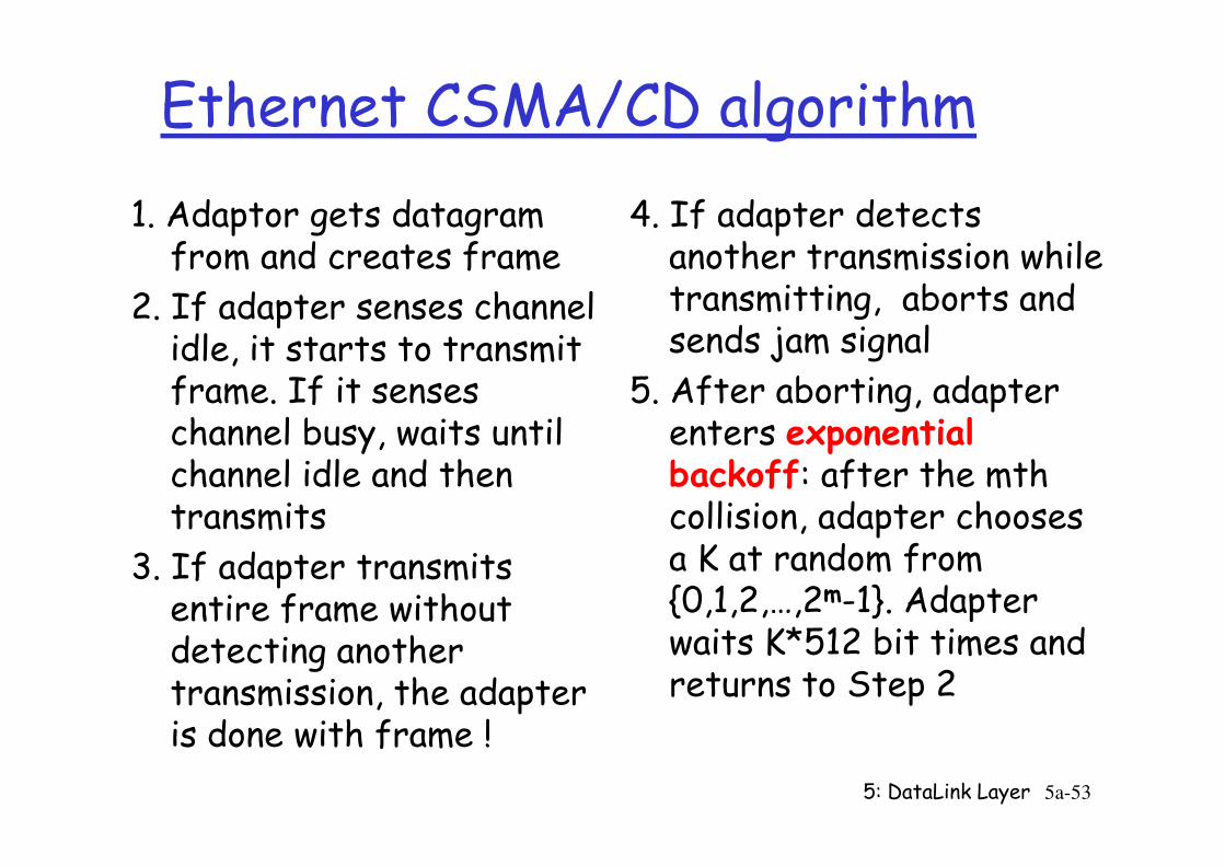
Ethernet CSMA/CD algorithm
1. Adaptor gets datagram from and creates frame
2. If adapter senses channel idle, it starts to transmit frame. If it senses channel busy, waits until
4. If adapter detects another transmission while transmitting, aborts and sends jam signal
5. After aborting, adapter enters exponential
5: DataLink Layer 5a-53
channel busy, waits until channel idle and then transmits
3. If adapter transmits entire frame without detecting another transmission, the adapter is done with frame !
enters exponential backoff: after the mth collision, adapter chooses a K at random from {0,1,2,…,2m-1}. Adapter waits K*512 bit times and returns to Step 2
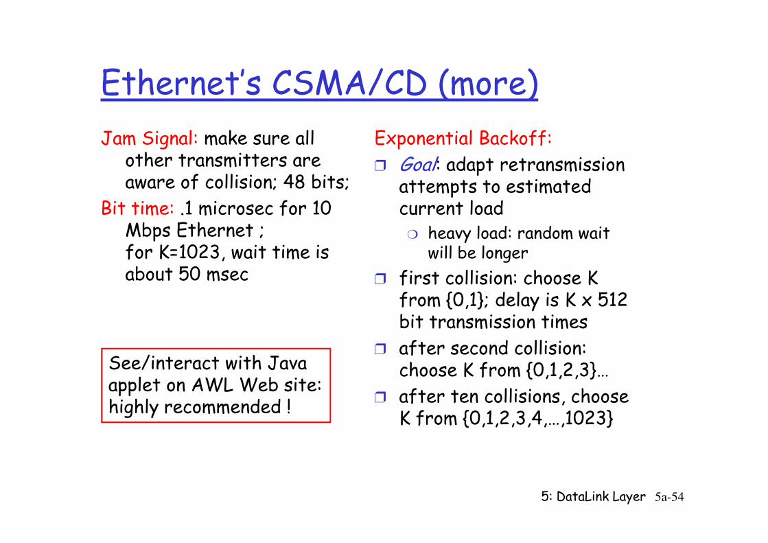
Ethernet’s CSMA/CD (more)
Jam Signal: make sure all other transmitters are aware of collision; 48 bits;
Bit time: .1 microsec for 10 Mbps Ethernet ;for K=1023, wait time is about 50 msec
Exponential Backoff:
r Goal: adapt retransmission attempts to estimated current load
m heavy load: random wait will be longer
r first collision: choose K
5: DataLink Layer 5a-54
about 50 msec r first collision: choose K from {0,1}; delay is K x 512 bit transmission times
r after second collision: choose K from {0,1,2,3}…
r after ten collisions, choose K from {0,1,2,3,4,…,1023}
See/interact with Javaapplet on AWL Web site:highly recommended !
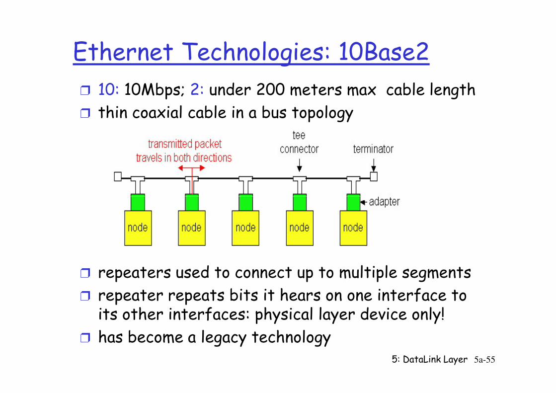
Ethernet Technologies: 10Base2
r 10: 10Mbps; 2: under 200 meters max cable length
r thin coaxial cable in a bus topology
5: DataLink Layer 5a-55
r repeaters used to connect up to multiple segments
r repeater repeats bits it hears on one interface to its other interfaces: physical layer device only!
r has become a legacy technology
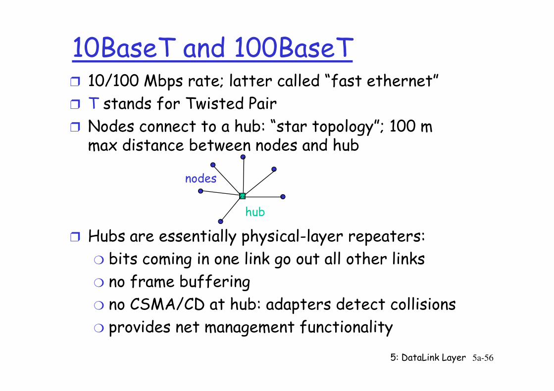
10BaseT and 100BaseTr 10/100 Mbps rate; latter called “fast ethernet”
r T stands for Twisted Pair
r Nodes connect to a hub: “star topology”; 100 m max distance between nodes and hub
nodes
5: DataLink Layer 5a-56
r Hubs are essentially physical-layer repeaters:
m bits coming in one link go out all other links
m no frame buffering
m no CSMA/CD at hub: adapters detect collisions
m provides net management functionality
hub
Fast EthernetrHigher bit rate media (100 Mbps) is available.
m Can it be used for Ethernet?
r Recall minimum frame length?m Set=512 bits by calculating time needed to detect collisions in Ethernets of upto 2.5km length, of 10Mbps bit rate
r Can higher bit rates be used without changing protocol specs, and still make it work?
5: DataLink Layer 5a-57
specs, and still make it work?m Frame transmission time for 512 bit frame @100Mbps ~ 5µsec m 5 µsec >= twice prop. delay m Should be <= (1/10th) of 2.5 km => ~200m
This is what was Fast Ethernet: transmission media was available, Ethernet wires were anyway not stretching very far away -> perfect solution say, for e.g. “server room” LAN
Gbit Ethernet
r use standard Ethernet frame format
r allows for point-to-point links and shared broadcast channels
r in shared mode, CSMA/CD is used; short distances between nodes to be efficient
5: DataLink Layer 5a-58
between nodes to be efficient
r uses hubs, called here “Buffered Distributors”
r Full-Duplex at 1 Gbps for point-to-point links
r 10 Gbps now !
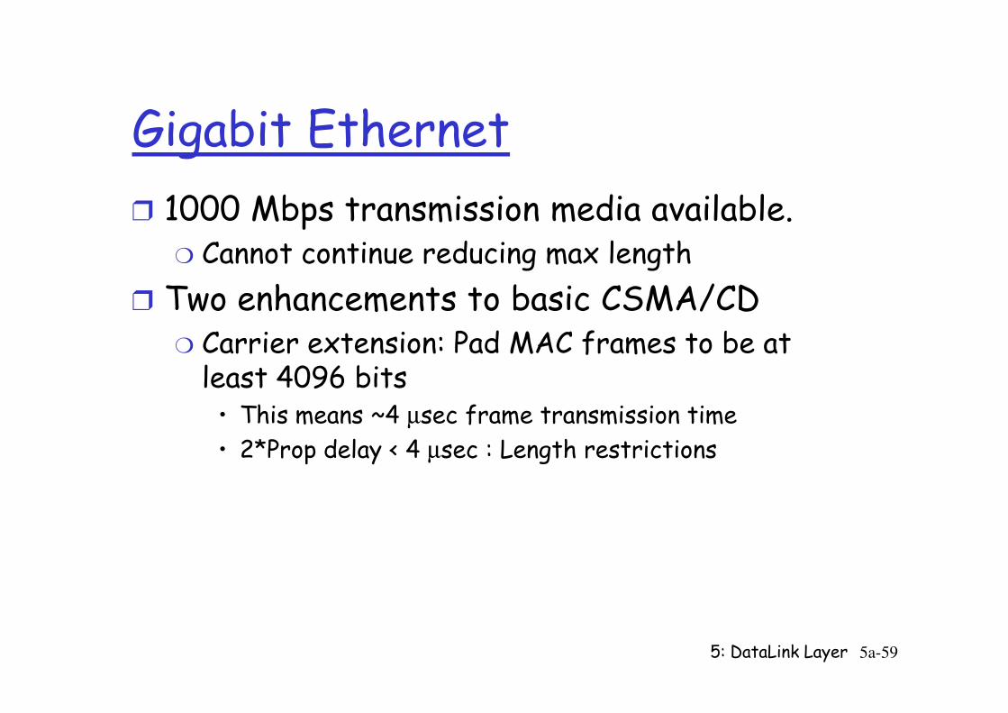
Gigabit Ethernet
r 1000 Mbps transmission media available. m Cannot continue reducing max length
r Two enhancements to basic CSMA/CDm Carrier extension: Pad MAC frames to be at least 4096 bits
5: DataLink Layer 5a-59
Carrier extension: Pad MAC frames to be at least 4096 bits• This means ~4 µsec frame transmission time
• 2*Prop delay < 4 µsec : Length restrictions
LAN Addresses and ARP
32-bit IP address:r network-layer addressr used to get datagram to destination IP network (recall IP network definition)
LAN (or MAC or physical or Ethernet) address:
5: DataLink Layer 5a-60
LAN (or MAC or physical or Ethernet) address: r used to get datagram from one interface to another physically-connected interface (same network)
r 48 bit MAC address (for most LANs) burned in the adapter ROM
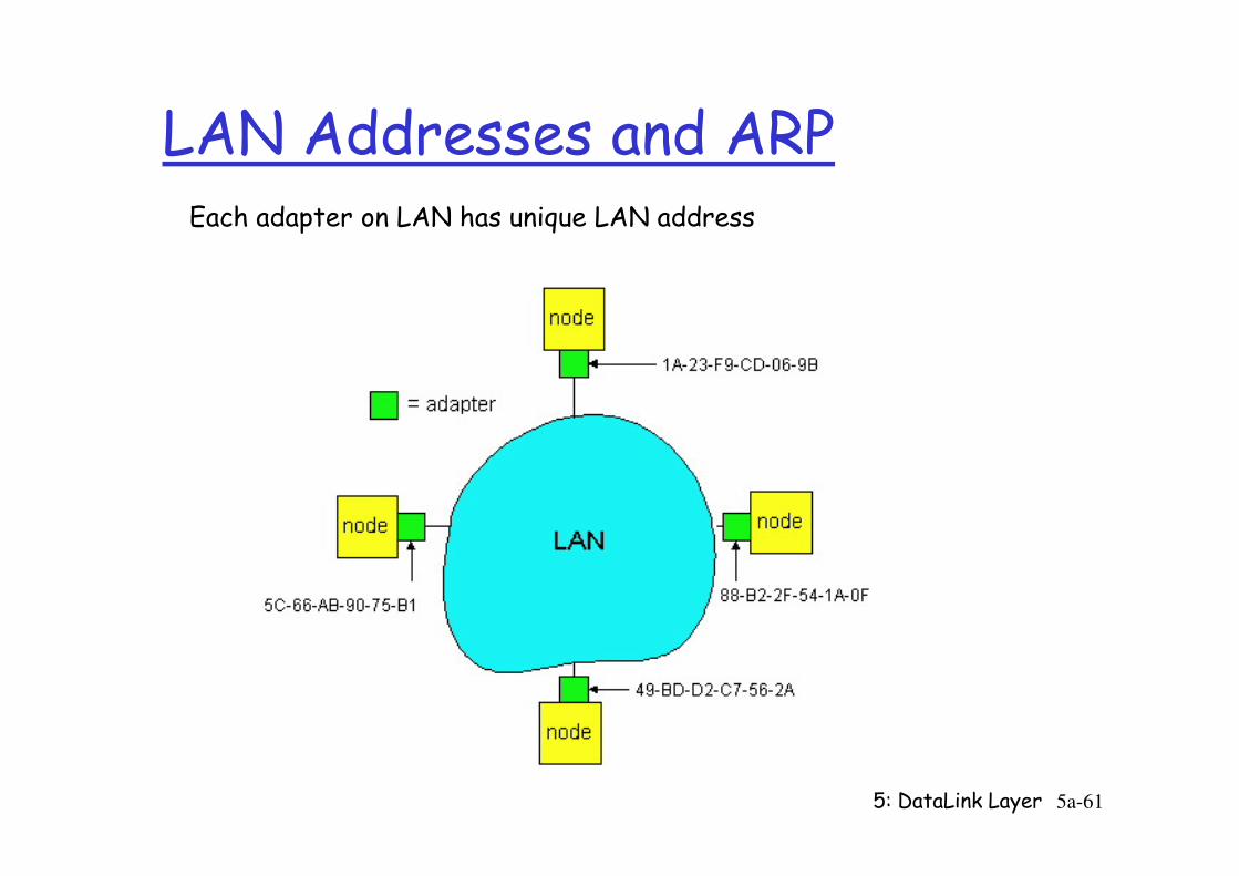
LAN Addresses and ARPEach adapter on LAN has unique LAN address
5: DataLink Layer 5a-61
LAN Address (more)
r MAC address allocation administered by IEEE
r manufacturer buys portion of MAC address space (to assure uniqueness)
r Analogy:
(a) MAC address: like Social Security Number
5: DataLink Layer 5a-62
(a) MAC address: like Social Security Number
(b) IP address: like postal address
r MAC flat address => portability m can move LAN card from one LAN to another
r IP hierarchical address NOT portablem depends on IP network to which node is attached
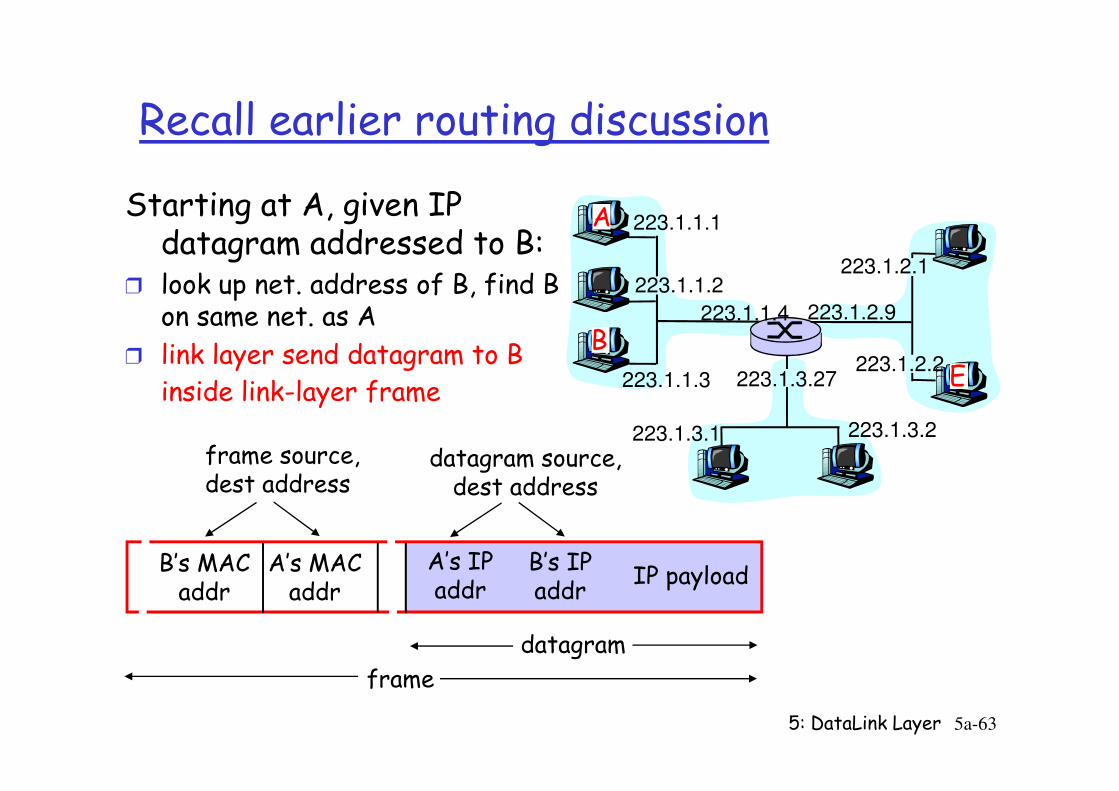
Recall earlier routing discussion
223.1.1.1
223.1.1.2
223.1.1.3
223.1.1.4 223.1.2.9
223.1.2.2
223.1.2.1
223.1.3.27
A
BE
Starting at A, given IP datagram addressed to B:
r look up net. address of B, find B on same net. as A
r link layer send datagram to B inside link-layer frame
5: DataLink Layer 5a-63
223.1.3.2223.1.3.1
inside link-layer frame
B’s MACaddr
A’s MACaddr
A’s IPaddr
B’s IPaddr
IP payload
datagram
frame
frame source,dest address
datagram source,dest address
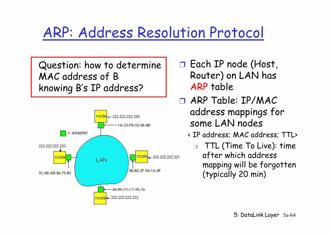
ARP: Address Resolution Protocol
r Each IP node (Host, Router) on LAN has ARP table
r ARP Table: IP/MAC address mappings for some LAN nodes
Question: how to determineMAC address of Bknowing B’s IP address?
5: DataLink Layer 5a-64
address mappings for some LAN nodes< IP address; MAC address; TTL>
m TTL (Time To Live): time after which address mapping will be forgotten (typically 20 min)
ARP protocol
r A wants to send datagram to B, and A knows B’s IP address.
r Suppose B’s MAC address is not in A’s ARP table.
r A broadcasts ARP query
r A caches (saves) IP-to-MAC address pair in its ARP table until information becomes old (times out)
m soft state: information that times out (goes
5: DataLink Layer 5a-65
r A broadcasts ARP query packet, containing B's IP address
m all machines on LAN receive ARP query
r B receives ARP packet, replies to A with its (B's) MAC address
m frame sent to A’s MAC address (unicast)
that times out (goes away) unless refreshed
r ARP is “plug-and-play”:m nodes create their ARP tables without intervention from net administrator
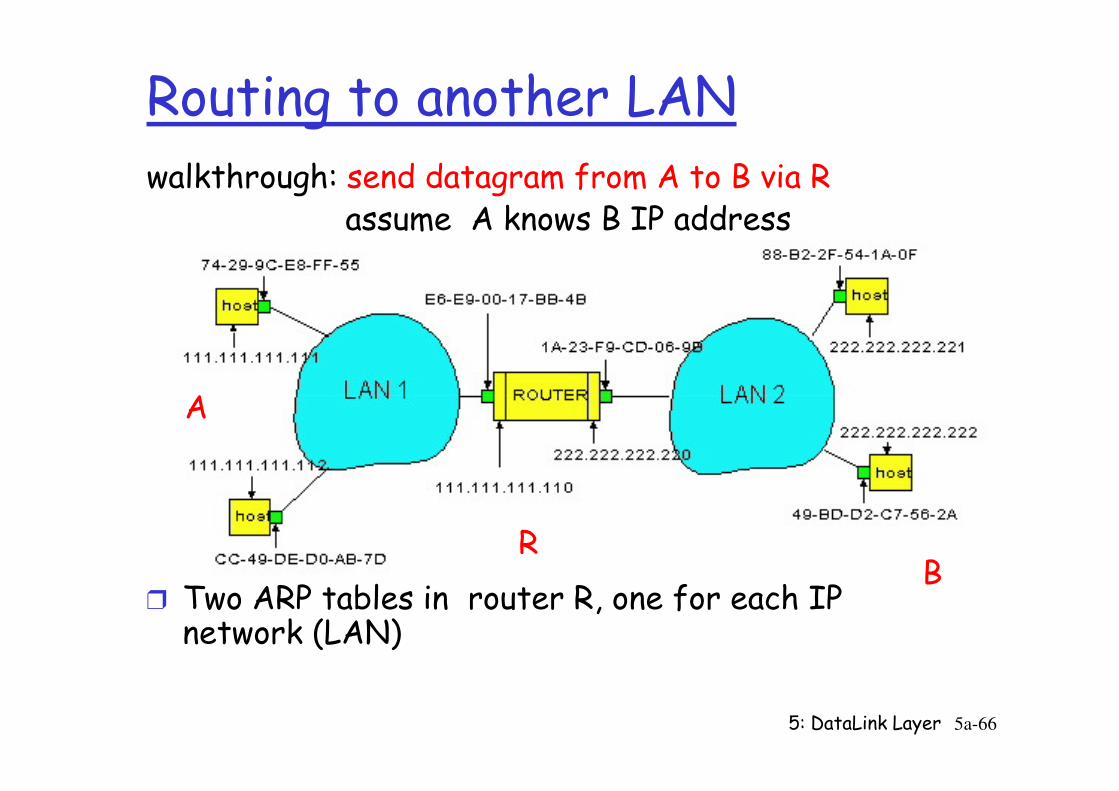
Routing to another LANwalkthrough: send datagram from A to B via R
assume A knows B IP address
A
5: DataLink Layer 5a-66
r Two ARP tables in router R, one for each IP network (LAN)
A
RB

r A creates datagram with source A, destination B
r A uses ARP to get R’s MAC address for 111.111.111.110
r A creates link-layer frame with R's MAC address as dest, frame contains A-to-B IP datagram
r A’s data link layer sends frame
r R’s data link layer receives frame
r R removes IP datagram from Ethernet frame, sees its destined to B
r R uses ARP to get B’s physical layer address
5: DataLink Layer 5a-67
R uses ARP to get B’s physical layer address
r R creates frame containing A-to-B IP datagram sends to B
A
RB
Chapter 5 outline
r 5.1 Introduction and services
r 5.2 Error detection and correction
r 5.3Multiple access
r 5.6 Hubs, bridges, and switches
r 5.7 Wireless links and LANs
r 5.8 PPP
5: DataLink Layer 5a-68
r 5.3Multiple access protocols
r 5.4 LAN addresses and ARP
r 5.5 Ethernet
r 5.8 PPP
r 5.9 ATM
r 5.10 Frame Relay
Interconnecting LAN segments
r Hubs
r Bridges
r Switchesm Remark: switches are essentially multi-port
5: DataLink Layer 5a-69
m Remark: switches are essentially multi-port bridges.
m What we say about bridges also holds for switches!
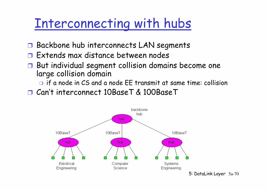
Interconnecting with hubs
r Backbone hub interconnects LAN segmentsr Extends max distance between nodesr But individual segment collision domains become one large collision domain
m if a node in CS and a node EE transmit at same time: collision
r Can’t interconnect 10BaseT & 100BaseT
5: DataLink Layer 5a-70
r Can’t interconnect 10BaseT & 100BaseT
Bridges
r Link layer device
m stores and forwards Ethernet frames
m examines frame header and selectivelyforwards frame based on MAC dest address
m when frame is to be forwarded on segment, uses CSMA/CD to access segment
5: DataLink Layer 5a-71
uses CSMA/CD to access segment
r transparent
m hosts are unaware of presence of bridges
r plug-and-play, self-learning
m bridges do not need to be configured
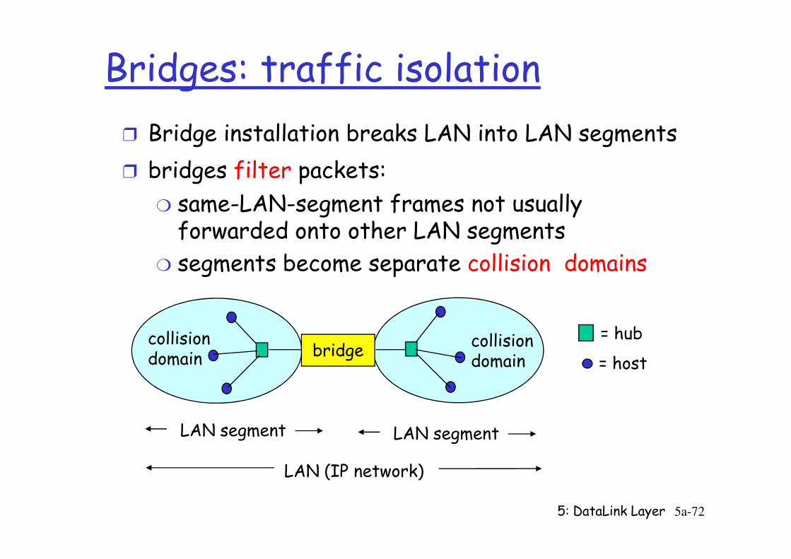
Bridges: traffic isolation
r Bridge installation breaks LAN into LAN segments
r bridges filter packets:
m same-LAN-segment frames not usually forwarded onto other LAN segments
m segments become separate collision domains
5: DataLink Layer 5a-72
bridgecollision domain
collision domain
= hub
= host
LAN (IP network)
LAN segment LAN segment
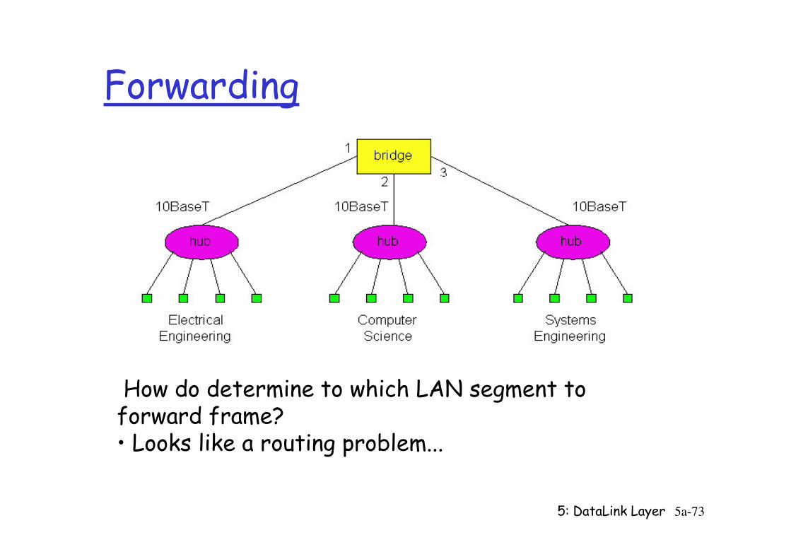
Forwarding
5: DataLink Layer 5a-73
How do determine to which LAN segment to forward frame?• Looks like a routing problem...
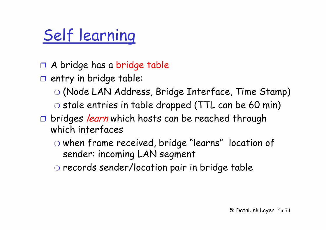
Self learning
r A bridge has a bridge table
r entry in bridge table:
m (Node LAN Address, Bridge Interface, Time Stamp)
m stale entries in table dropped (TTL can be 60 min)
r bridges learn which hosts can be reached through
5: DataLink Layer 5a-74
r bridges learn which hosts can be reached through which interfaces
m when frame received, bridge “learns” location of sender: incoming LAN segment
m records sender/location pair in bridge table
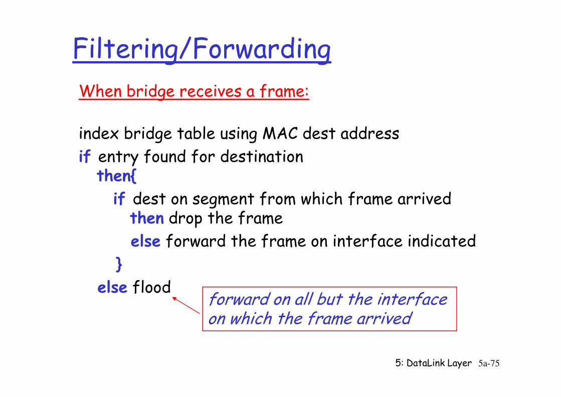
Filtering/Forwarding
When bridge receives a frame:
index bridge table using MAC dest address
if entry found for destinationthen{
if dest on segment from which frame arrived
5: DataLink Layer 5a-75
if dest on segment from which frame arrivedthen drop the frame
else forward the frame on interface indicated
}
else floodforward on all but the interface on which the frame arrived
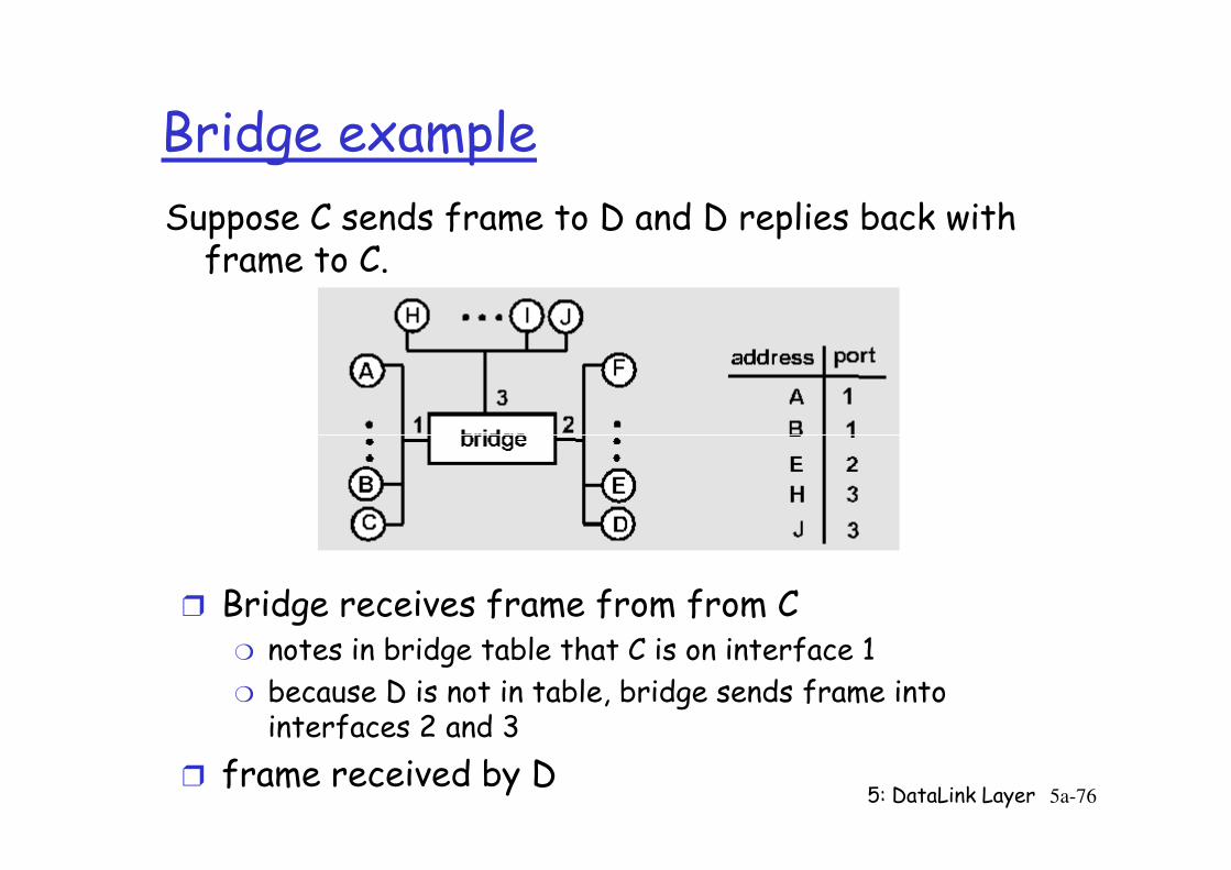
Bridge example
Suppose C sends frame to D and D replies back with frame to C.
5: DataLink Layer 5a-76
r Bridge receives frame from from Cm notes in bridge table that C is on interface 1
m because D is not in table, bridge sends frame into interfaces 2 and 3
r frame received by D
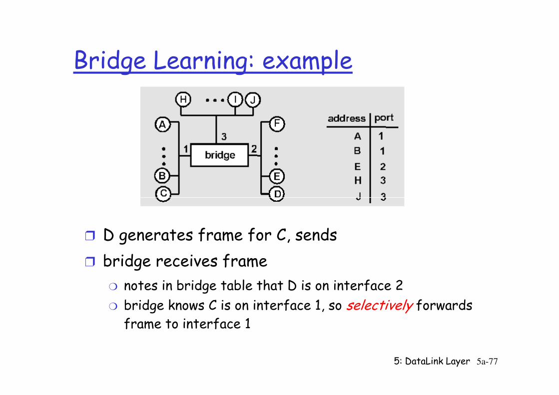
Bridge Learning: example
5: DataLink Layer 5a-77
r D generates frame for C, sends
r bridge receives frame
m notes in bridge table that D is on interface 2
m bridge knows C is on interface 1, so selectively forwards frame to interface 1
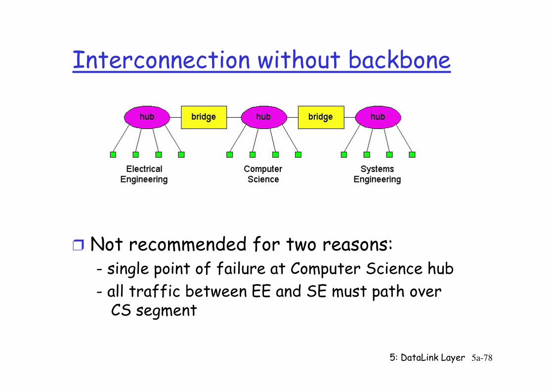
Interconnection without backbone
5: DataLink Layer 5a-78
r Not recommended for two reasons:- single point of failure at Computer Science hub
- all traffic between EE and SE must path over CS segment
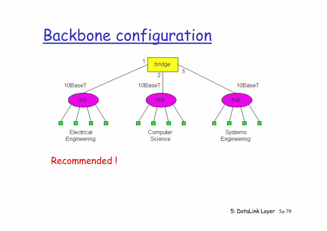
Backbone configuration
5: DataLink Layer 5a-79
Recommended !
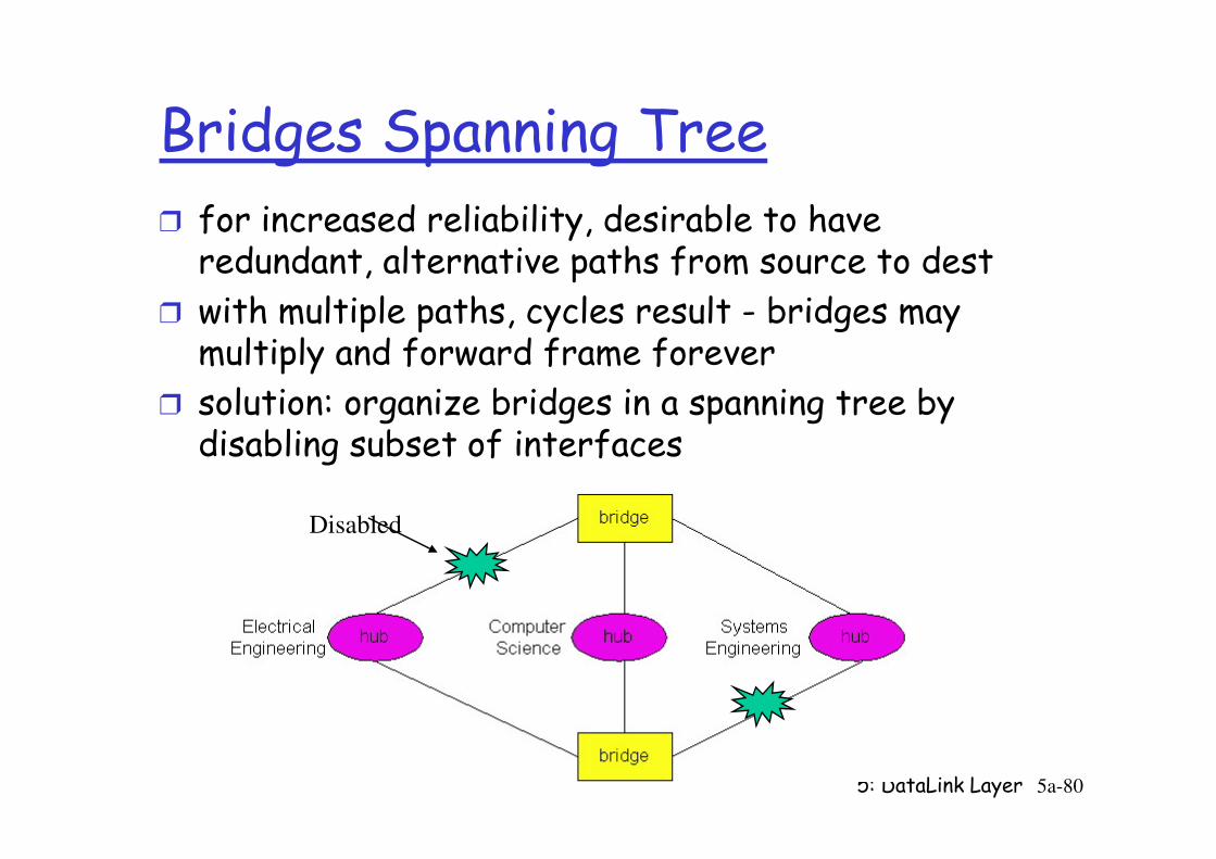
Bridges Spanning Treer for increased reliability, desirable to have redundant, alternative paths from source to dest
r with multiple paths, cycles result - bridges may multiply and forward frame forever
r solution: organize bridges in a spanning tree by disabling subset of interfaces
5: DataLink Layer 5a-80
disabling subset of interfaces
Disabled
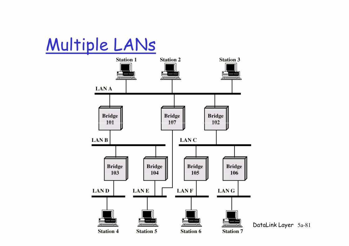
Multiple LANs
5: DataLink Layer 5a-81
Needed: Routing
rComplex large LANs need alternative routesm Load balancingm Fault tolerance
rBridge must decide whether to forward frameBridge must decide which LAN to forward frame on
5: DataLink Layer 5a-82
m Bridge must decide which LAN to forward frame on
rRouting selected for each source-destination pair of LANs
m Done in configurationm Usually least hop routem Only changed when topology changes
Spanning Tree
r Bridge automatically develops routing table
r Automatically update in response to changesm Frame forwarding
5: DataLink Layer 5a-83
Frame forwarding
m Address learning
m Loop resolution
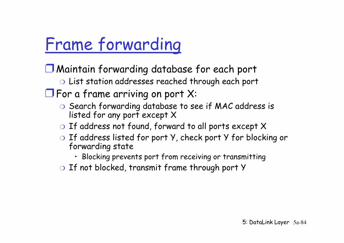
Frame forwardingrMaintain forwarding database for each port
m List station addresses reached through each port
rFor a frame arriving on port X:m Search forwarding database to see if MAC address is listed for any port except XIf address not found, forward to all ports except X
5: DataLink Layer 5a-84
m If address not found, forward to all ports except Xm If address listed for port Y, check port Y for blocking or forwarding state• Blocking prevents port from receiving or transmitting
m If not blocked, transmit frame through port Y
Address Learning
rWhen frame arrives at port X, it has come form the LAN attached to port X
rUse the source address to update forwarding database for port X to include that address
5: DataLink Layer 5a-85
database for port X to include that address
rTimer on each entry in database (reset whenever frame received)
rEach time frame arrives, source address checked against forwarding database
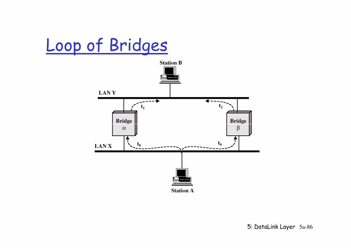
Loop of Bridges
5: DataLink Layer 5a-86
Spanning Tree Algorithm
r Creates a logical, or “active” topology that behaves like a spanning treem Makes alternate bridges redundant
m Is run periodically, so will discover failures and use alternate bridges if necessary
5: DataLink Layer 5a-87
use alternate bridges if necessary
Reference: Fred Halsall: “Data Communications, Computer Networks and Open Systems”, 4th Edition.
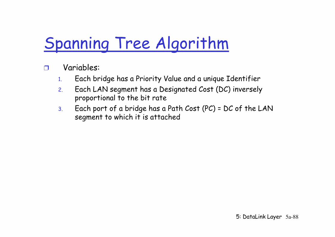
Spanning Tree Algorithmr Variables:
1. Each bridge has a Priority Value and a unique Identifier
2. Each LAN segment has a Designated Cost (DC) inversely proportional to the bit rate
3. Each port of a bridge has a Path Cost (PC) = DC of the LAN segment to which it is attached
5: DataLink Layer 5a-88
segment to which it is attached
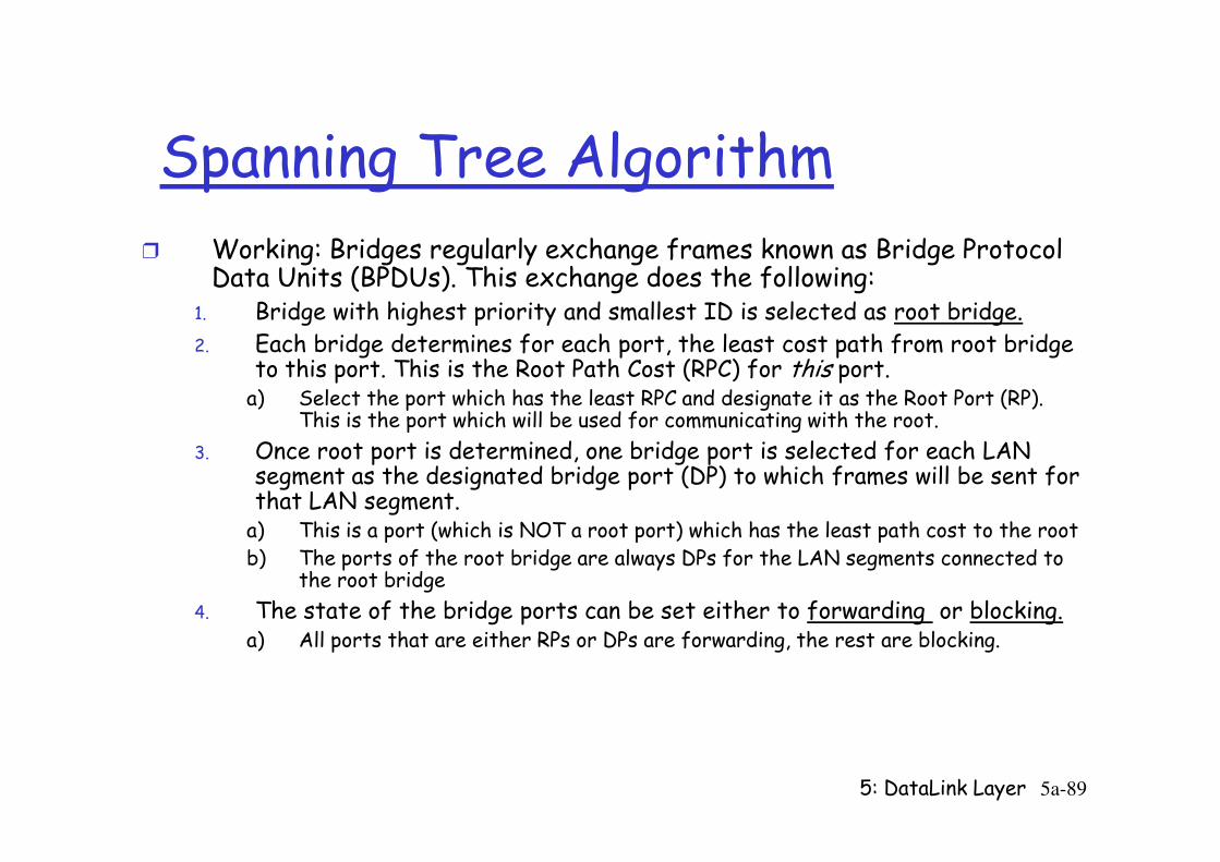
Spanning Tree Algorithmr Working: Bridges regularly exchange frames known as Bridge Protocol
Data Units (BPDUs). This exchange does the following:1. Bridge with highest priority and smallest ID is selected as root bridge.2. Each bridge determines for each port, the least cost path from root bridge
to this port. This is the Root Path Cost (RPC) for this port.a) Select the port which has the least RPC and designate it as the Root Port (RP).
This is the port which will be used for communicating with the root.
5: DataLink Layer 5a-89
This is the port which will be used for communicating with the root.
3. Once root port is determined, one bridge port is selected for each LAN segment as the designated bridge port (DP) to which frames will be sent for that LAN segment. a) This is a port (which is NOT a root port) which has the least path cost to the rootb) The ports of the root bridge are always DPs for the LAN segments connected to
the root bridge
4. The state of the bridge ports can be set either to forwarding or blocking.a) All ports that are either RPs or DPs are forwarding, the rest are blocking.

Topology Initializationr BPDUs are sent to a broadcast MAC address of all bridges on the LANr All bridges initially assume they are the root bridger Each BPDU contains (self ID, root ID, transmitting port ID, RPC of this
port)r If necessary,
m Update root ID based on received BPDUsAdd path cost of the port on which frame was received to the RPC in the
5: DataLink Layer 5a-90
m Add path cost of the port on which frame was received to the RPC in the frame
m Sends out this new info on all other ports with all updated Idsm Procedure repeated by all bridges
• Will determine RPCs of each port• Will select Root Ports based on this
m Two or more bridges on the same segment will exchange BPDUs so that designated bridge-port can be seleted
Topology Changer Root bridge regularly transmits BPDUs, forwarded by all
bridges on all ports
r Bridges will keep timers associated with each of its forwarding ports
rWhen timers expire, procedure similar to topology initialization is done
5: DataLink Layer 5a-91
initialization is donem Details…
Some bridge featuresr Isolates collision domains resulting in higher total max throughput
r limitless number of nodes and geographical coverage
r Can connect different Ethernet types
Transparent (“plug-and-play”): no configuration
5: DataLink Layer 5a-92
r Transparent (“plug-and-play”): no configuration necessary
Bridges vs. Routers
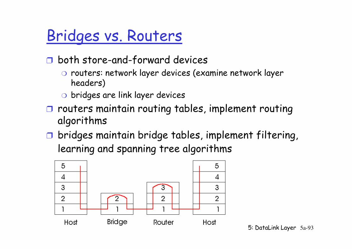
r both store-and-forward devicesm routers: network layer devices (examine network layer headers)
m bridges are link layer devices
r routers maintain routing tables, implement routing algorithms
5: DataLink Layer 5a-93
algorithms
r bridges maintain bridge tables, implement filtering, learning and spanning tree algorithms
Routers vs. Bridges
Bridges + and -
+ Bridge operation is simpler requiring less packet processing
+ Bridge tables are self learning
- All traffic confined to spanning tree, even when
5: DataLink Layer 5a-94
- All traffic confined to spanning tree, even when alternative bandwidth is available
- Bridges do not offer protection from broadcast storms
Routers vs. Bridges
Routers + and -
+ arbitrary topologies can be supported, cycling is limited by TTL counters (and good routing protocols)
+ provide protection against broadcast storms
- require IP address configuration (not plug and play)
5: DataLink Layer 5a-95
- require IP address configuration (not plug and play)
- require higher packet processing
r bridges do well in small (few hundred hosts) while routers used in large networks (thousands of hosts)
Ethernet Switches
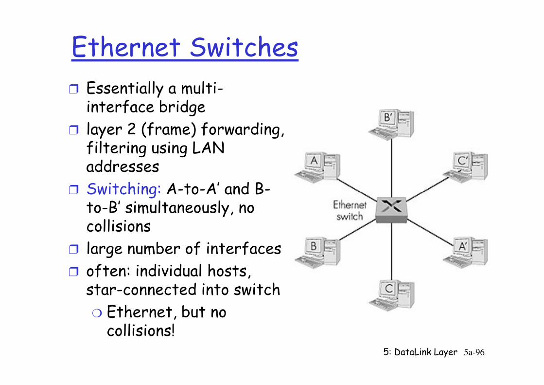
r Essentially a multi-interface bridge
r layer 2 (frame) forwarding, filtering using LAN addresses
r Switching: A-to-A’ and B-
5: DataLink Layer 5a-96
r Switching: A-to-A’ and B-to-B’ simultaneously, no collisions
r large number of interfaces
r often: individual hosts, star-connected into switch
m Ethernet, but no collisions!
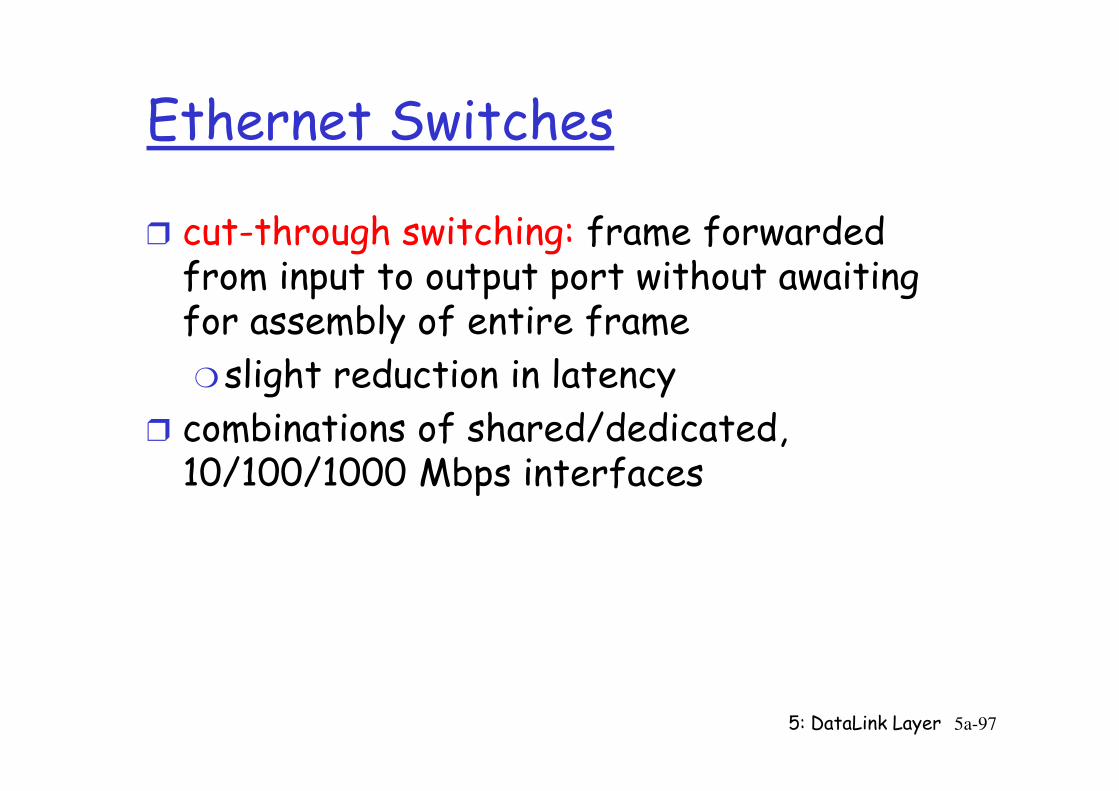
Ethernet Switches
r cut-through switching: frame forwarded from input to output port without awaiting for assembly of entire frame
m slight reduction in latency
5: DataLink Layer 5a-97
slight reduction in latency
r combinations of shared/dedicated, 10/100/1000 Mbps interfaces
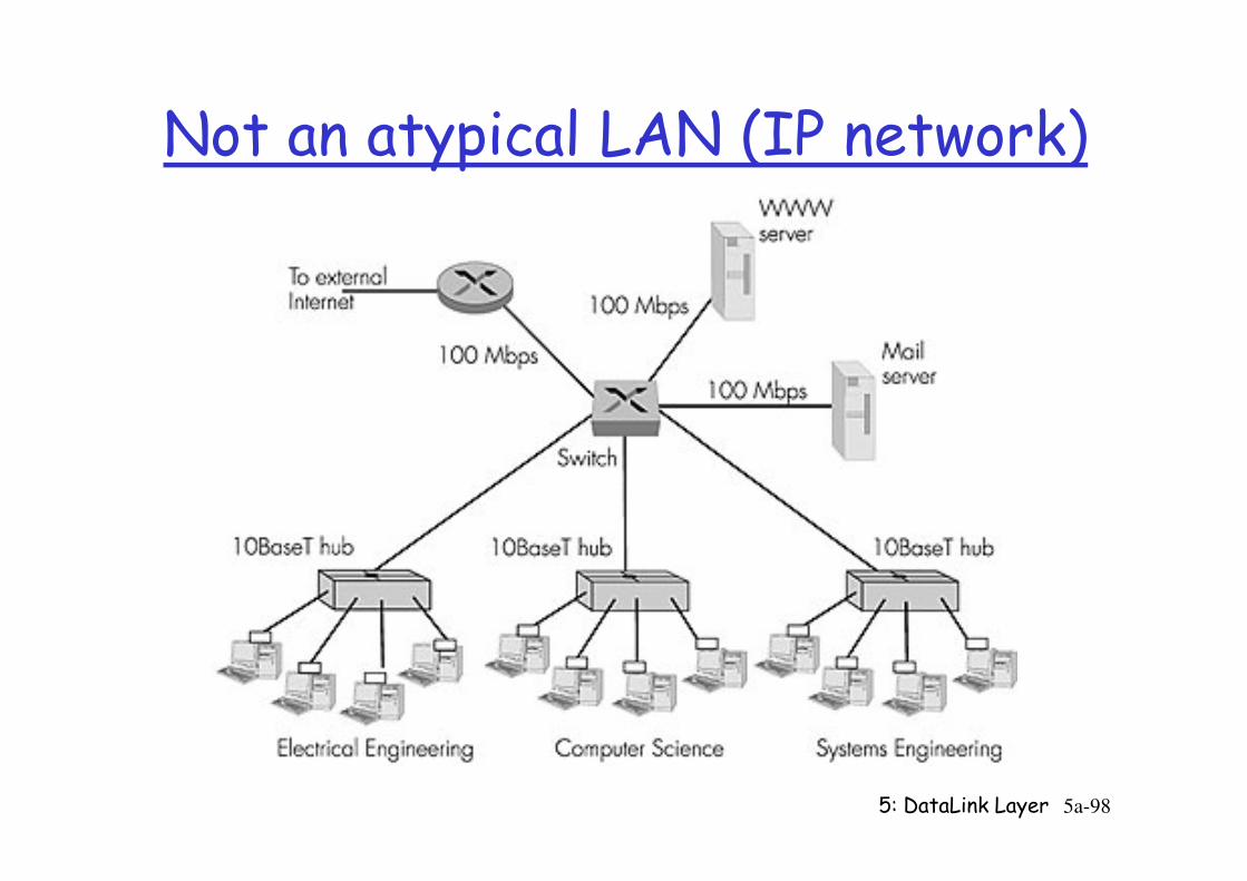
Not an atypical LAN (IP network)
Dedicated
Shared
5: DataLink Layer 5a-98
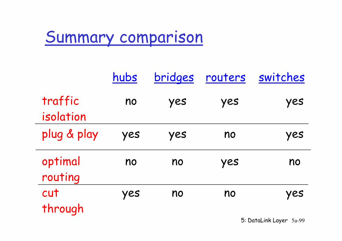
Summary comparison
hubs bridges routers switches
trafficisolation
no yes yes yes
5: DataLink Layer 5a-99
isolation
plug & play yes yes no yes
optimalrouting
no no yes no
cutthrough
yes no no yes
Chapter 5 outline
r 5.1 Introduction and services
r 5.2 Error detection and correction
r 5.3Multiple access
r 5.6 Hubs, bridges, and switches
r 5.7 Wireless links and LANs
r 5.8 PPP
5: DataLink Layer 5a-
100
r 5.3Multiple access protocols
r 5.4 LAN addresses and ARP
r 5.5 Ethernet
r 5.8 PPP
r 5.9 ATM
r 5.10 Frame Relay
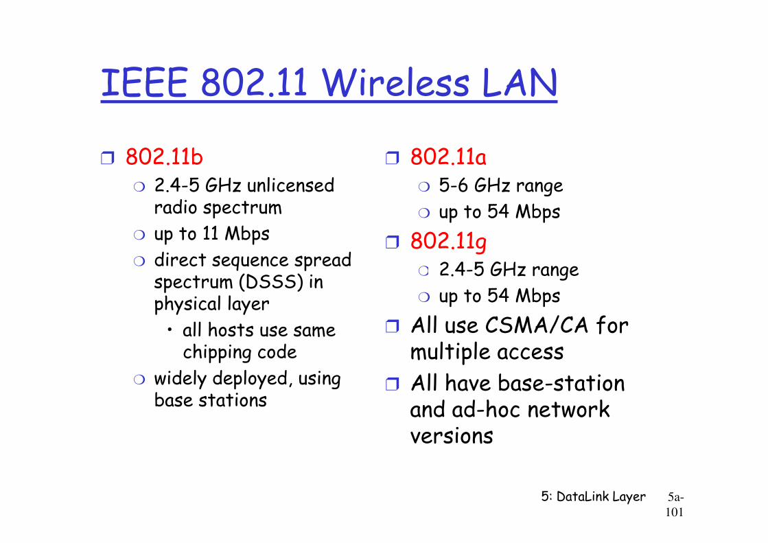
IEEE 802.11 Wireless LAN
r 802.11bm 2.4-5 GHz unlicensed radio spectrum
m up to 11 Mbps
m direct sequence spread spectrum (DSSS) in
r 802.11am 5-6 GHz range
m up to 54 Mbps
r 802.11gm 2.4-5 GHz range
5: DataLink Layer 5a-
101
spectrum (DSSS) in physical layer
• all hosts use same chipping code
m widely deployed, using base stations
m 2.4-5 GHz range
m up to 54 Mbps
r All use CSMA/CA for multiple access
r All have base-station and ad-hoc network versions
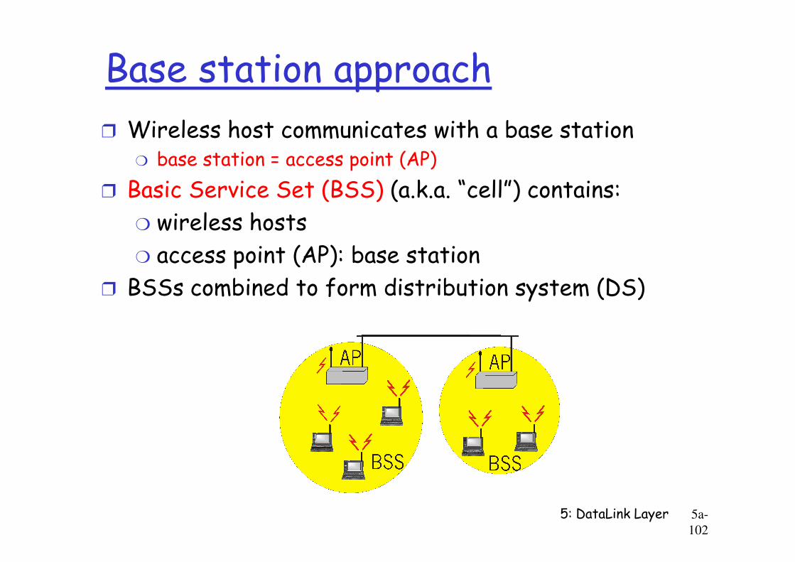
Base station approach
r Wireless host communicates with a base stationm base station = access point (AP)
r Basic Service Set (BSS) (a.k.a. “cell”) contains:
m wireless hosts
m access point (AP): base station
r BSSs combined to form distribution system (DS)
5: DataLink Layer 5a-
102
r BSSs combined to form distribution system (DS)
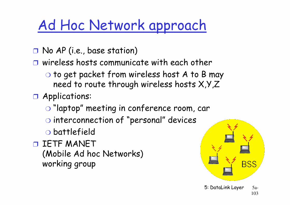
Ad Hoc Network approach
r No AP (i.e., base station)
r wireless hosts communicate with each other
m to get packet from wireless host A to B may need to route through wireless hosts X,Y,Z
r Applications:
“laptop” meeting in conference room, car
5: DataLink Layer 5a-
103
m “laptop” meeting in conference room, car
m interconnection of “personal” devices
m battlefield
r IETF MANET (Mobile Ad hoc Networks) working group
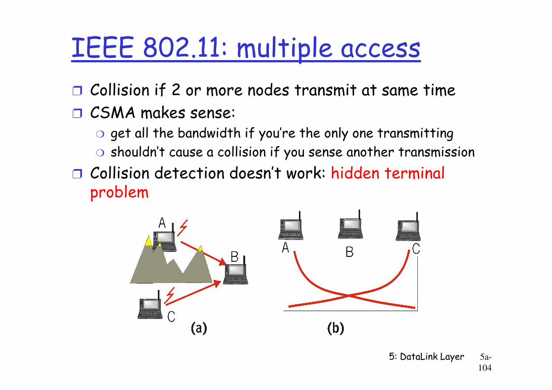
IEEE 802.11: multiple access
r Collision if 2 or more nodes transmit at same time
r CSMA makes sense:m get all the bandwidth if you’re the only one transmitting
m shouldn’t cause a collision if you sense another transmission
r Collision detection doesn’t work: hidden terminal problem
5: DataLink Layer 5a-
104
problem
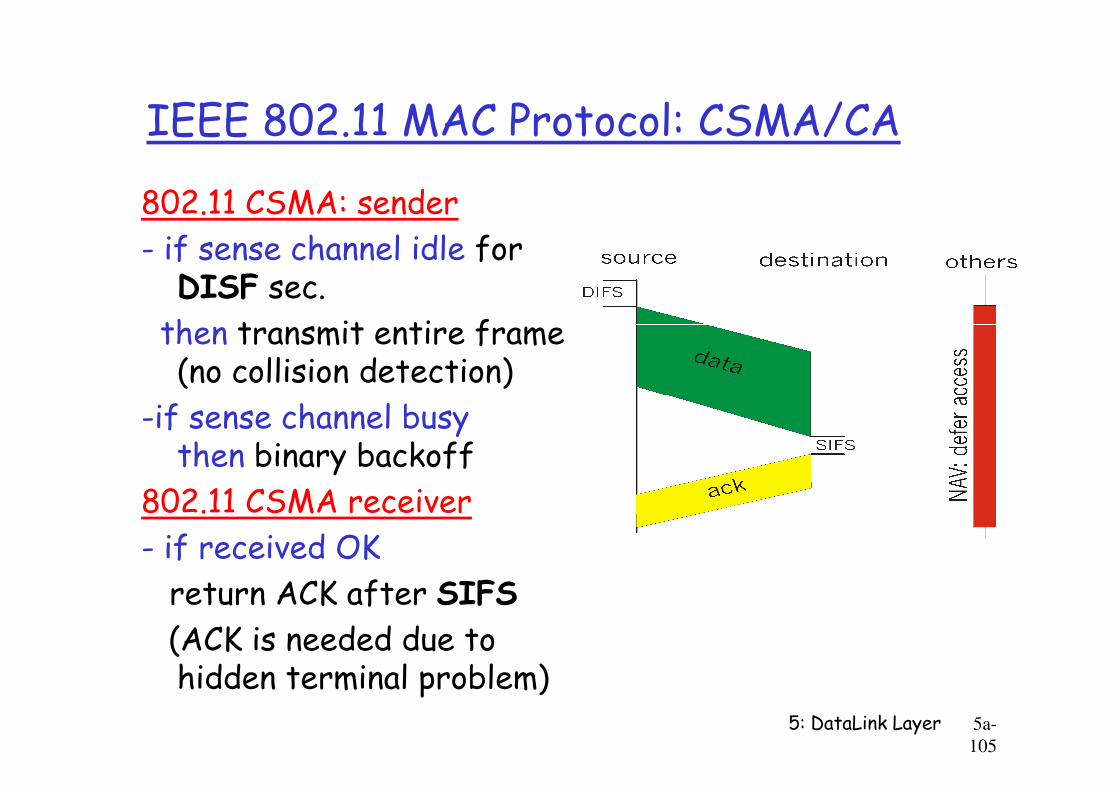
IEEE 802.11 MAC Protocol: CSMA/CA
802.11 CSMA: sender
- if sense channel idle for DISF sec.
then transmit entire frame (no collision detection)
-if sense channel busy
5: DataLink Layer 5a-
105
-if sense channel busy then binary backoff
802.11 CSMA receiver
- if received OK
return ACK after SIFS
(ACK is needed due to hidden terminal problem)
Collision avoidance mechanisms
r Problem:m two nodes, hidden from each other, transmit complete frames to base station
m wasted bandwidth for long duration !
r Solution:
m small reservation packets
5: DataLink Layer 5a-
106
m small reservation packets
m nodes track reservation interval with internal “network allocation vector” (NAV)
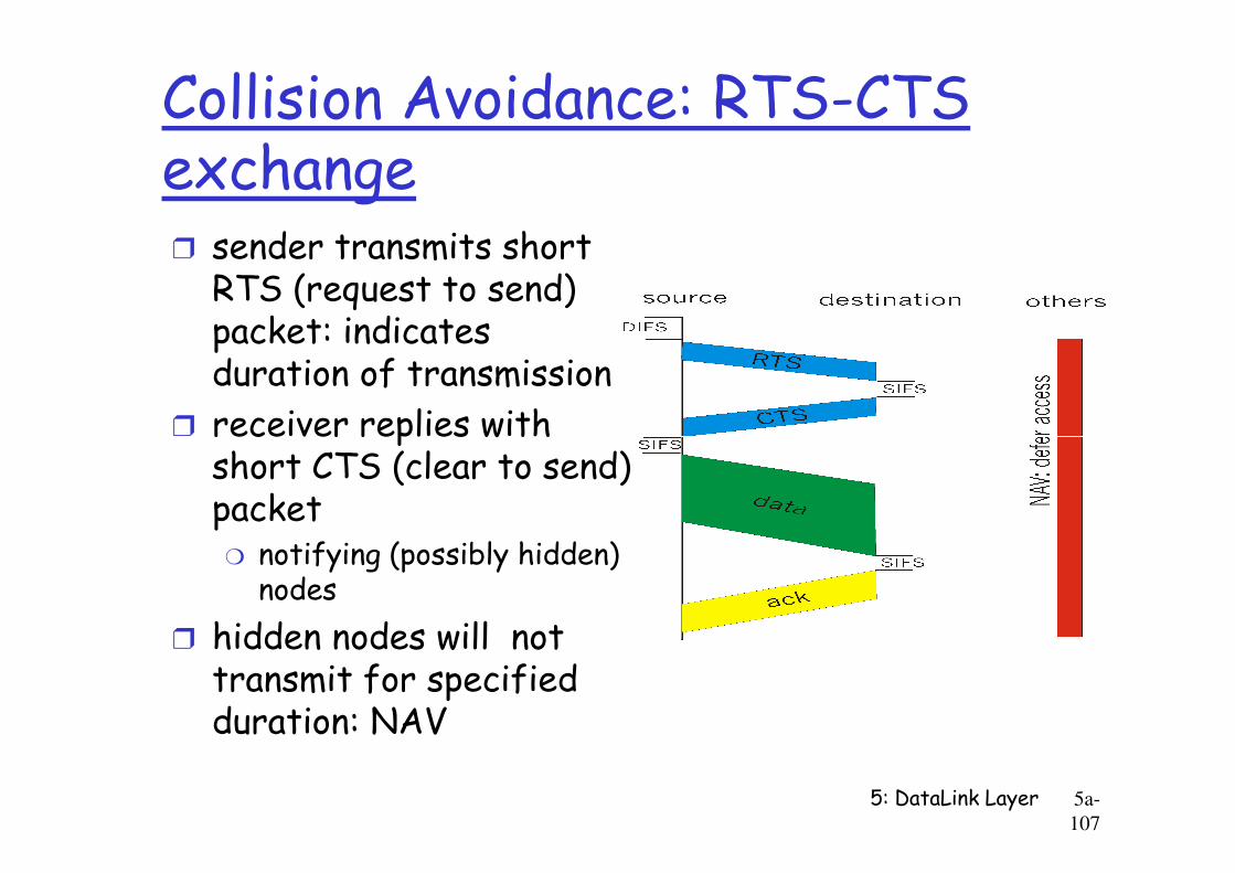
Collision Avoidance: RTS-CTS exchanger sender transmits short RTS (request to send) packet: indicates duration of transmission
r receiver replies with
5: DataLink Layer 5a-
107
r receiver replies with short CTS (clear to send) packet
m notifying (possibly hidden) nodes
r hidden nodes will not transmit for specified duration: NAV
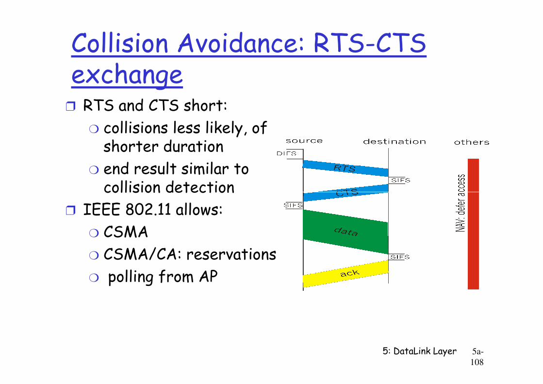
Collision Avoidance: RTS-CTS exchange
r RTS and CTS short:
m collisions less likely, of shorter duration
m end result similar to collision detection
5: DataLink Layer 5a-
108
collision detection
r IEEE 802.11 allows:
m CSMA
m CSMA/CA: reservations
m polling from AP
A word about Bluetooth
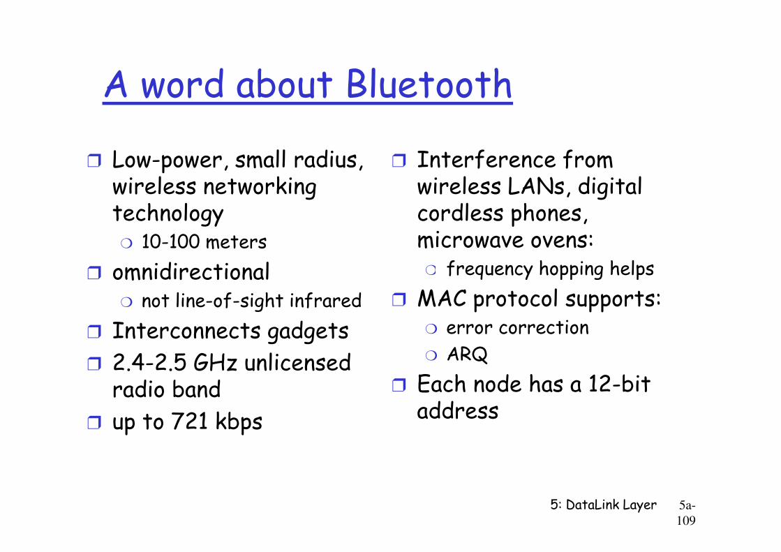
r Low-power, small radius, wireless networking technology
m 10-100 meters
r omnidirectional
r Interference from wireless LANs, digital cordless phones, microwave ovens:
m frequency hopping helps
5: DataLink Layer 5a-
109
r omnidirectionalm not line-of-sight infrared
r Interconnects gadgets
r 2.4-2.5 GHz unlicensed radio band
r up to 721 kbps
m frequency hopping helps
r MAC protocol supports:m error correction
m ARQ
r Each node has a 12-bit address

Chapter 5 outline
r 5.1 Introduction and services
r 5.2 Error detection and correction
r 5.3Multiple access
r 5.6 Hubs, bridges, and switches
r 5.7 Wireless links and LANs
r 5.8 PPP
5: DataLink Layer 5a-110
r 5.3Multiple access protocols
r 5.4 LAN addresses and ARP
r 5.5 Ethernet
r 5.8 PPP
r 5.9 ATM
r 5.10 Frame Relay
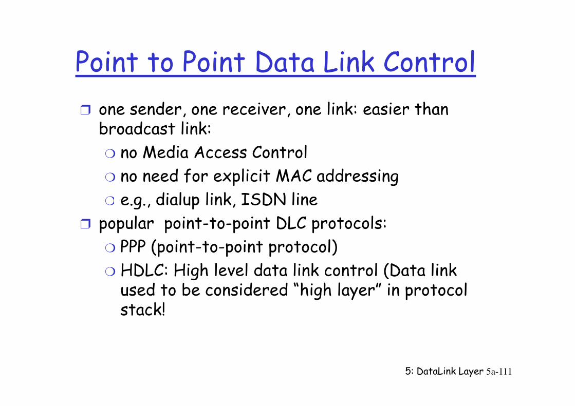
Point to Point Data Link Control
r one sender, one receiver, one link: easier than broadcast link:
m no Media Access Control
m no need for explicit MAC addressing
m e.g., dialup link, ISDN line
5: DataLink Layer 5a-111
m e.g., dialup link, ISDN line
r popular point-to-point DLC protocols:
m PPP (point-to-point protocol)
m HDLC: High level data link control (Data link used to be considered “high layer” in protocol stack!
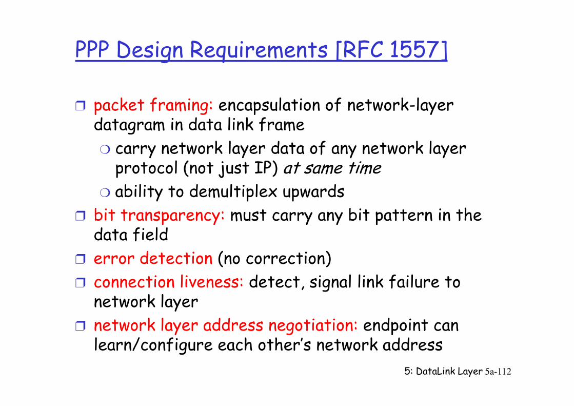
PPP Design Requirements [RFC 1557]
r packet framing: encapsulation of network-layer datagram in data link frame
m carry network layer data of any network layer protocol (not just IP) at same time
m ability to demultiplex upwards
bit transparency: must carry any bit pattern in the
5: DataLink Layer 5a-112
r bit transparency: must carry any bit pattern in the data field
r error detection (no correction)
r connection liveness: detect, signal link failure to network layer
r network layer address negotiation: endpoint can learn/configure each other’s network address
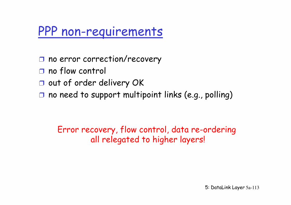
PPP non-requirements
r no error correction/recovery
r no flow control
r out of order delivery OK
r no need to support multipoint links (e.g., polling)
5: DataLink Layer 5a-113
Error recovery, flow control, data re-ordering all relegated to higher layers!

PPP Data Frame
r Flag: delimiter (framing)
r Address: does nothing (only one option)
r Control: does nothing; in the future possible multiple control fields
r Protocol: upper layer protocol to which frame
5: DataLink Layer 5a-114
r Protocol: upper layer protocol to which frame delivered (eg, PPP-LCP, IP, IPCP, etc)
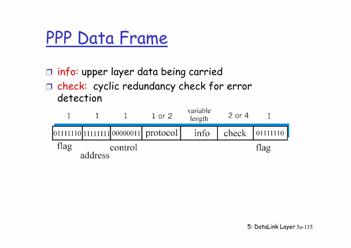
PPP Data Frame
r info: upper layer data being carried
r check: cyclic redundancy check for error detection
5: DataLink Layer 5a-115
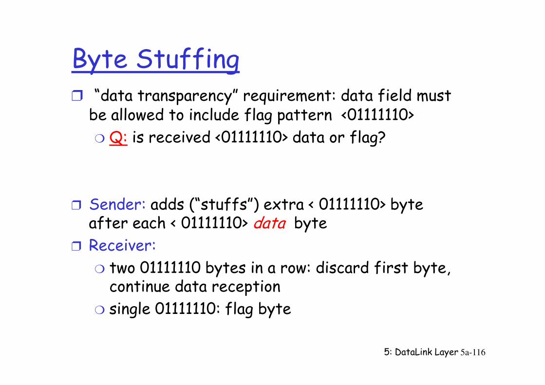
Byte Stuffingr “data transparency” requirement: data field must be allowed to include flag pattern <01111110>
m Q: is received <01111110> data or flag?
Sender: adds (“stuffs”) extra < 01111110> byte
5: DataLink Layer 5a-116
r Sender: adds (“stuffs”) extra < 01111110> byte after each < 01111110> data byte
r Receiver:
m two 01111110 bytes in a row: discard first byte, continue data reception
m single 01111110: flag byte
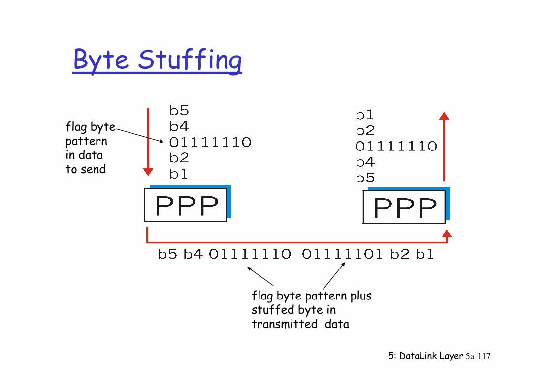
Byte Stuffing
flag bytepatternin datato send
5: DataLink Layer 5a-117
flag byte pattern plusstuffed byte in transmitted data
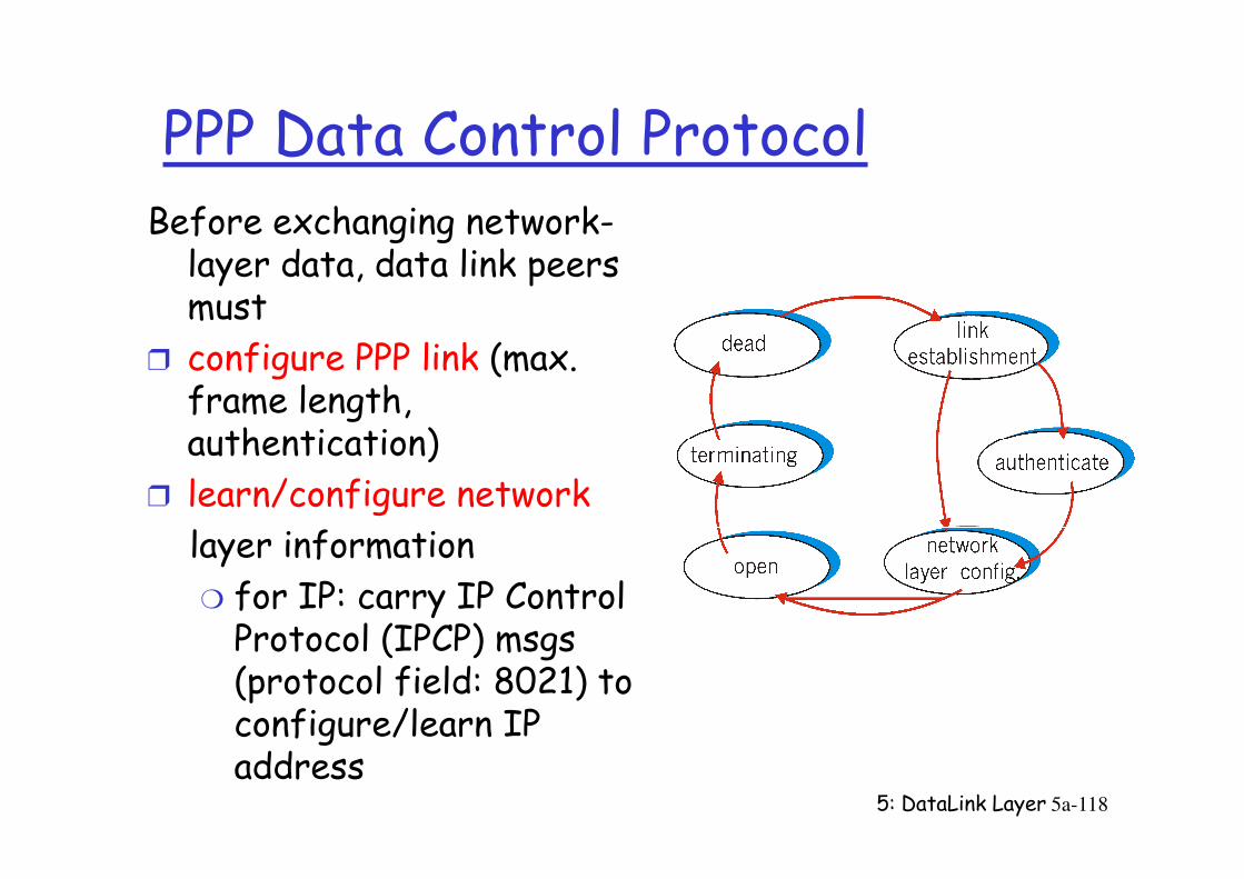
PPP Data Control ProtocolBefore exchanging network-layer data, data link peers must
r configure PPP link (max. frame length, authentication)
5: DataLink Layer 5a-118
authentication)
r learn/configure network
layer information
m for IP: carry IP Control Protocol (IPCP) msgs (protocol field: 8021) to configure/learn IP address
Chapter 5 outline
r 5.1 Introduction and services
r 5.2 Error detection and correction
r 5.3Multiple access
r 5.6 Hubs, bridges, and switches
r 5.7 Wireless links and LANs
r 5.8 PPP
5: DataLink Layer 5a-119
r 5.3Multiple access protocols
r 5.4 LAN addresses and ARP
r 5.5 Ethernet
r 5.8 PPP
r 5.9 ATM
r 5.10 Frame Relay
Asynchronous Transfer Mode: ATM
r 1990’s/00 standard for high-speed (155Mbps to 622 Mbps and higher) Broadband Integrated Service Digital Network architecture
r Goal: integrated, end-end transport of carry voice, video, datameeting timing/QoS requirements of voice, video
5: DataLink Layer 5a-
120
m meeting timing/QoS requirements of voice, video (versus Internet best-effort model)
m “next generation” telephony: technical roots in telephone world
m packet-switching (fixed length packets, called “cells”) using virtual circuits
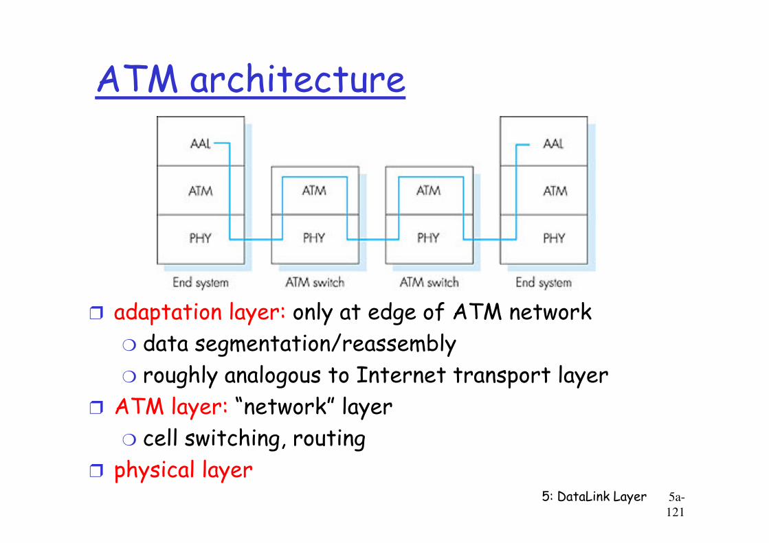
ATM architecture
5: DataLink Layer 5a-
121
r adaptation layer: only at edge of ATM network
m data segmentation/reassembly
m roughly analogous to Internet transport layer
r ATM layer: “network” layer
m cell switching, routing
r physical layer
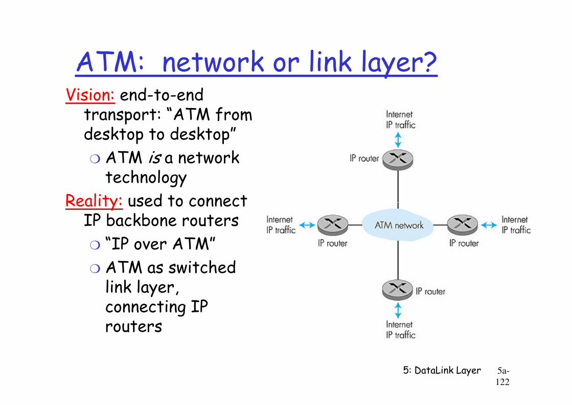
ATM: network or link layer?Vision: end-to-end transport: “ATM from desktop to desktop”
m ATM is a network technology
Reality: used to connect
5: DataLink Layer 5a-
122
Reality: used to connect IP backbone routers
m “IP over ATM”
m ATM as switched link layer, connecting IP routers
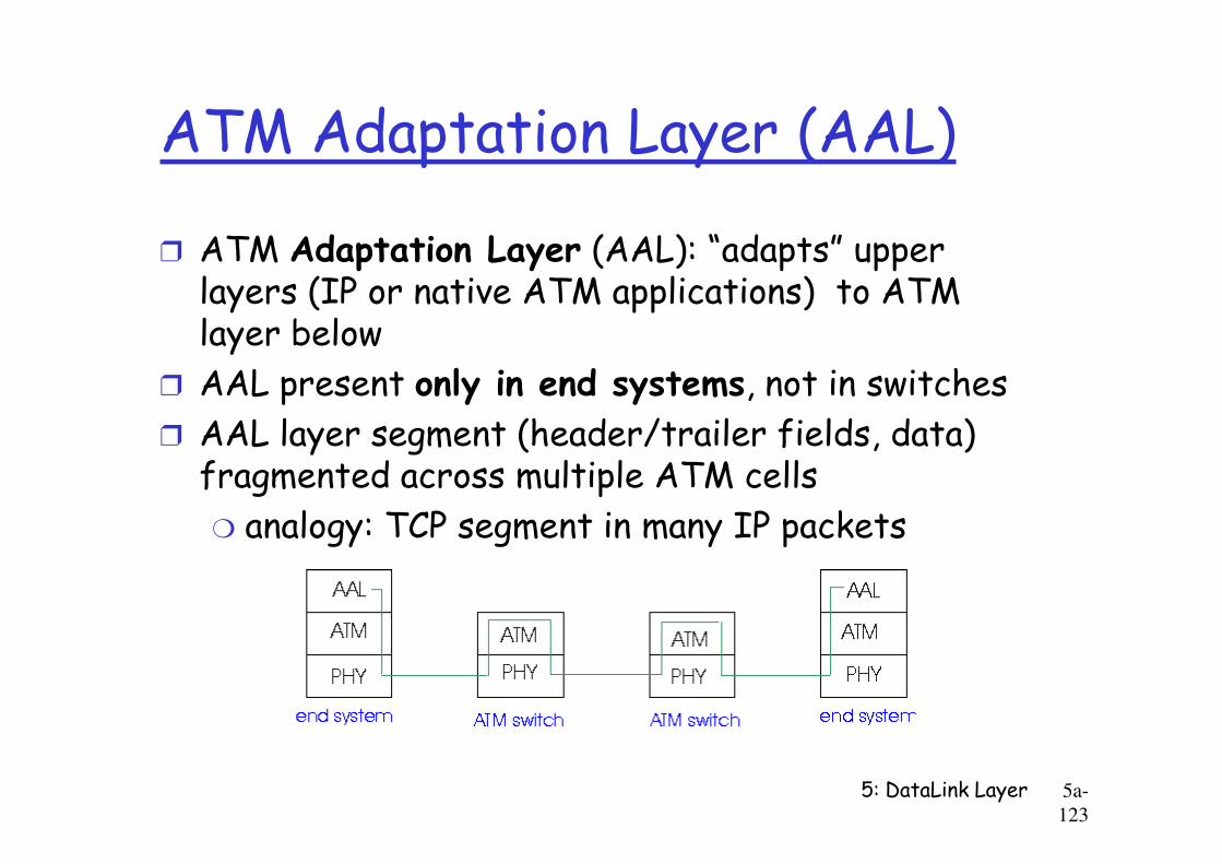
ATM Adaptation Layer (AAL)
r ATM Adaptation Layer (AAL): “adapts” upper layers (IP or native ATM applications) to ATM layer below
r AAL present only in end systems, not in switches
r AAL layer segment (header/trailer fields, data)
5: DataLink Layer 5a-
123
r AAL layer segment (header/trailer fields, data) fragmented across multiple ATM cells
m analogy: TCP segment in many IP packets
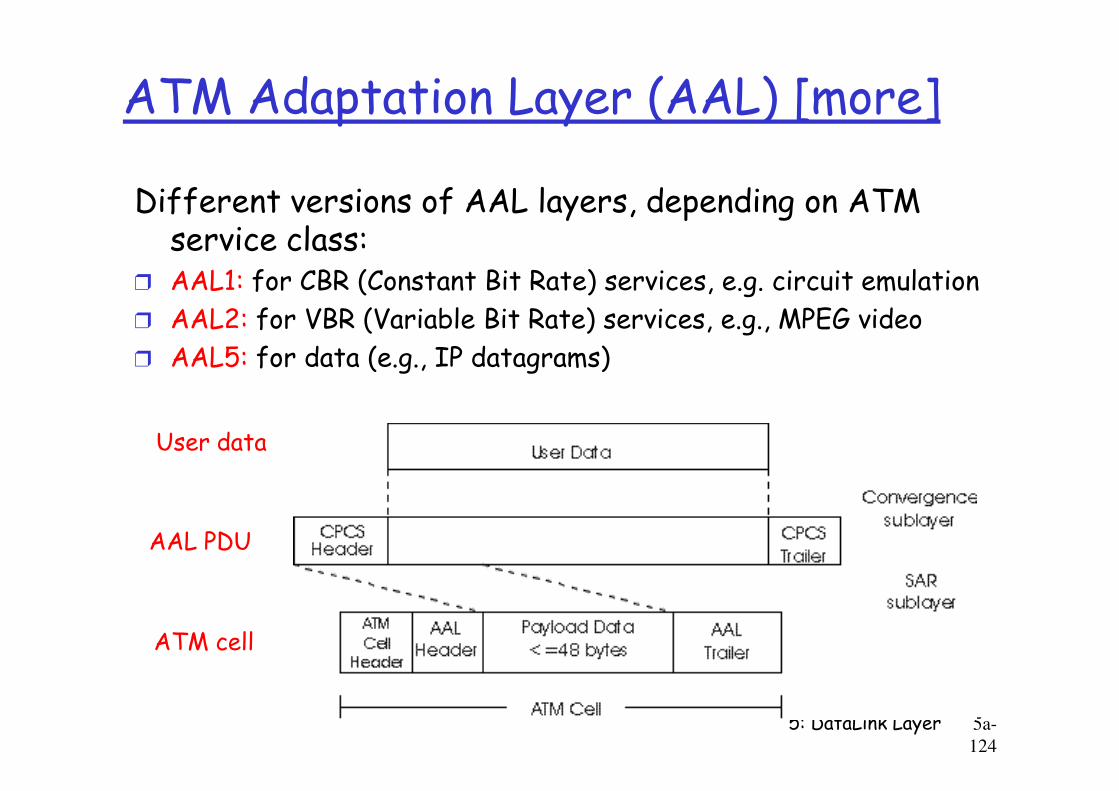
ATM Adaptation Layer (AAL) [more]
Different versions of AAL layers, depending on ATM service class:
r AAL1: for CBR (Constant Bit Rate) services, e.g. circuit emulation
r AAL2: for VBR (Variable Bit Rate) services, e.g., MPEG video
r AAL5: for data (e.g., IP datagrams)
5: DataLink Layer 5a-
124
AAL PDU
ATM cell
User data
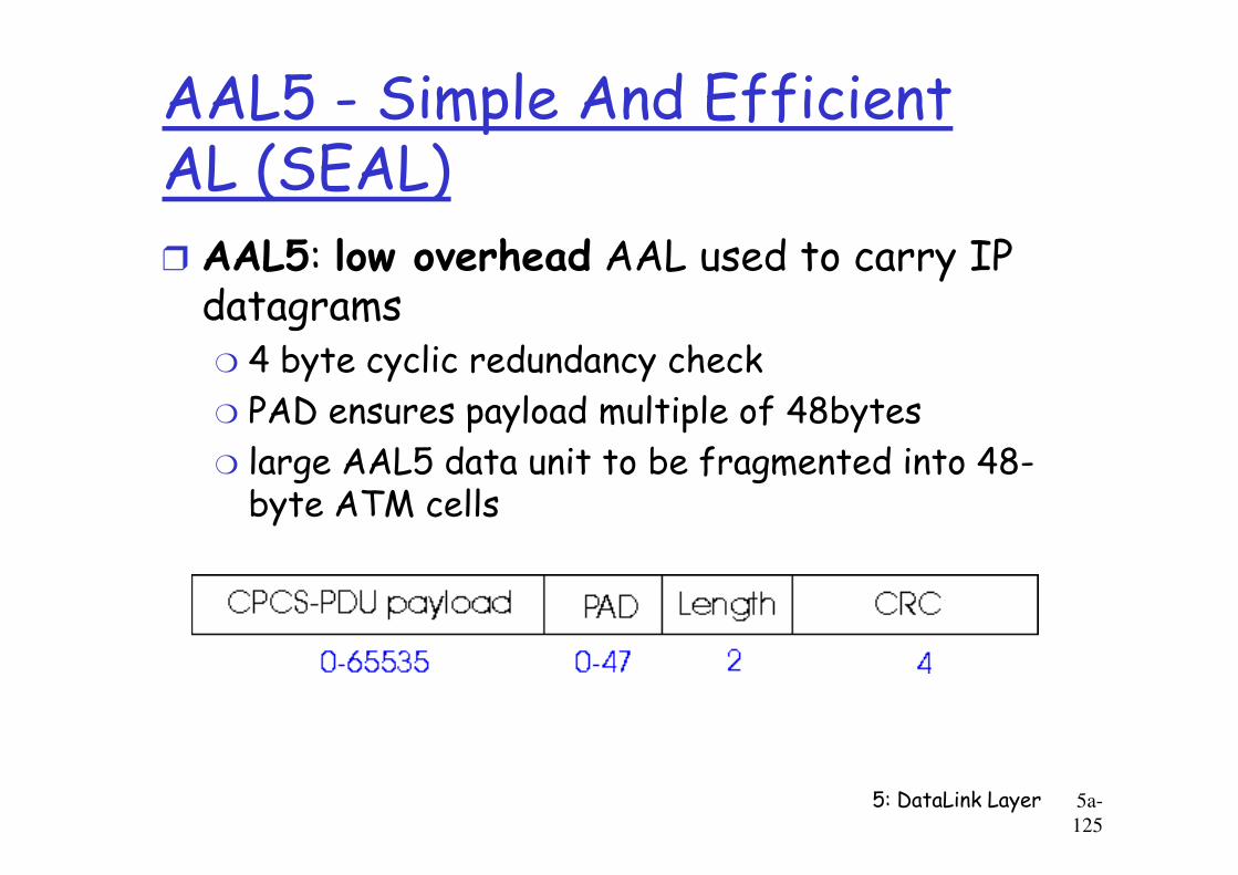
AAL5 - Simple And Efficient AL (SEAL)r AAL5: low overhead AAL used to carry IP datagramsm 4 byte cyclic redundancy check
m PAD ensures payload multiple of 48bytes
large AAL5 data unit to be fragmented into 48-
5: DataLink Layer 5a-
125
m large AAL5 data unit to be fragmented into 48-byte ATM cells
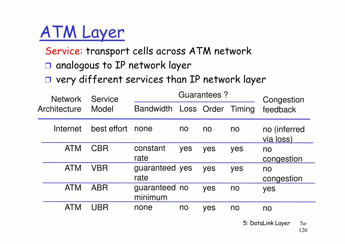
ATM LayerService: transport cells across ATM network
r analogous to IP network layer
r very different services than IP network layer
NetworkArchitecture
ServiceModel Bandwidth Loss Order Timing
Congestionfeedback
Guarantees ?
5: DataLink Layer 5a-
126
Internet
ATM
ATM
ATM
ATM
best effort
CBR
VBR
ABR
UBR
none
constantrateguaranteedrateguaranteed minimumnone
no
yes
yes
no
no
no
yes
yes
yes
yes
no
yes
yes
no
no
no (inferredvia loss)nocongestionnocongestionyes
no
ATM Layer: Virtual Circuitsr VC transport: cells carried on VC from source to dest
m call setup, teardown for each call before data can flowm each packet carries VC identifier (not destination ID)
m every switch on source-dest path maintain “state” for each passing connection
m link,switch resources (bandwidth, buffers) may be allocated to
5: DataLink Layer 5a-
127
m link,switch resources (bandwidth, buffers) may be allocated to VC: to get circuit-like perf.
r Permanent VCs (PVCs)
m long lasting connections
m typically: “permanent” route between to IP routers
r Switched VCs (SVC):
m dynamically set up on per-call basis
ATM VCs
r Advantages of ATM VC approach:
m QoS performance guarantee for connection mapped to VC (bandwidth, delay, delay jitter)
r Drawbacks of ATM VC approach:
m Inefficient support of datagram traffic
5: DataLink Layer 5a-
128
m Inefficient support of datagram traffic
m one PVC between each source/dest pair) does not scale (N*2 connections needed)
m SVC introduces call setup latency, processing overhead for short lived connections
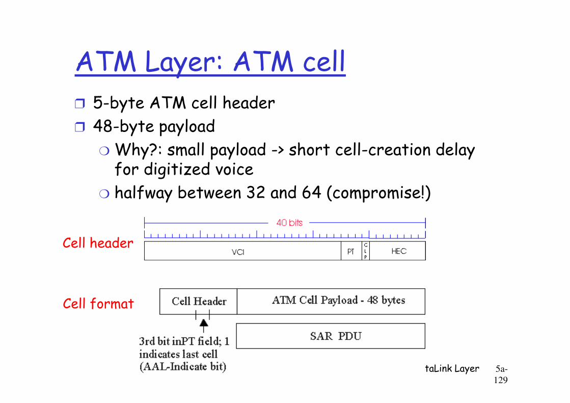
ATM Layer: ATM cellr 5-byte ATM cell header
r 48-byte payload
m Why?: small payload -> short cell-creation delay for digitized voice
m halfway between 32 and 64 (compromise!)
5: DataLink Layer 5a-
129
halfway between 32 and 64 (compromise!)
Cell header
Cell format
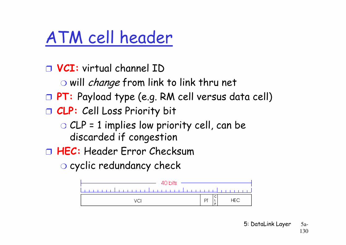
ATM cell header
r VCI: virtual channel ID
m will change from link to link thru netr PT: Payload type (e.g. RM cell versus data cell)
r CLP: Cell Loss Priority bit
m CLP = 1 implies low priority cell, can be
5: DataLink Layer 5a-
130
m CLP = 1 implies low priority cell, can be discarded if congestion
r HEC: Header Error Checksum
m cyclic redundancy check
ATM Physical Layer (more)
Two pieces (sublayers) of physical layer:r Transmission Convergence Sublayer (TCS): adapts ATM layer above to PMD sublayer below
r Physical Medium Dependent: depends on physical medium being used
5: DataLink Layer 5a-
131
medium being used
TCS Functions:
m Header checksum generation: 8 bits CRC
m Cell delineation
m With “unstructured” PMD sublayer, transmission of idle cells when no data cells to send
ATM Physical Layer
Physical Medium Dependent (PMD) sublayerr SONET/SDH: transmission frame structure (like a container carrying bits);
m bit synchronization;
bandwidth partitions (TDM);
5: DataLink Layer 5a-
132
m bandwidth partitions (TDM);
m several speeds: OC3 = 155.52 Mbps; OC12 = 622.08 Mbps; OC48 = 2.45 Gbps, OC192 = 9.6 Gbps
r TI/T3: transmission frame structure (old telephone hierarchy): 1.5 Mbps/ 45 Mbps
r unstructured: just cells (busy/idle)
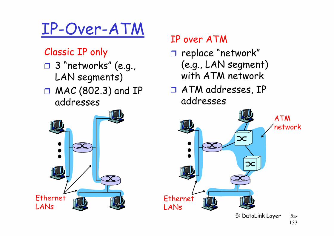
IP-Over-ATMClassic IP only
r 3 “networks” (e.g., LAN segments)
r MAC (802.3) and IP addresses
IP over ATM
r replace “network” (e.g., LAN segment) with ATM network
r ATM addresses, IP addresses
ATM
5: DataLink Layer 5a-
133
ATMnetwork
EthernetLANs
EthernetLANs
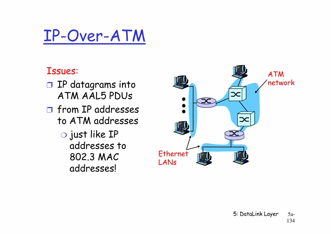
IP-Over-ATM
Issues:
r IP datagrams into ATM AAL5 PDUs
r from IP addresses to ATM addresses
ATMnetwork
5: DataLink Layer 5a-
134
to ATM addresses
m just like IP addresses to 802.3 MAC addresses!
EthernetLANs
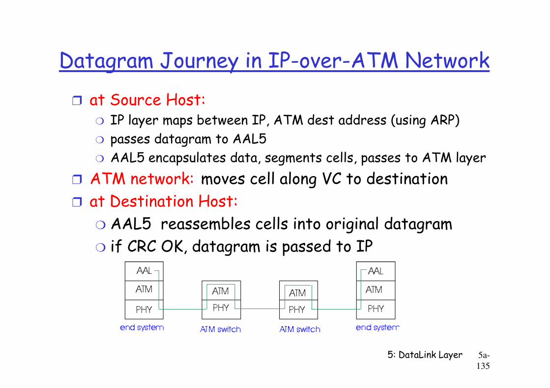
Datagram Journey in IP-over-ATM Network
r at Source Host:m IP layer maps between IP, ATM dest address (using ARP)
m passes datagram to AAL5
m AAL5 encapsulates data, segments cells, passes to ATM layer
r ATM network: moves cell along VC to destination
at Destination Host:
5: DataLink Layer 5a-
135
r at Destination Host:
m AAL5 reassembles cells into original datagram
m if CRC OK, datagram is passed to IP
Chapter 5 outline
r 5.1 Introduction and services
r 5.2 Error detection and correction
r 5.3Multiple access
r 5.6 Hubs, bridges, and switches
r 5.7 Wireless links and LANs
r 5.8 PPP
5: DataLink Layer 5a-
136
r 5.3Multiple access protocols
r 5.4 LAN addresses and ARP
r 5.5 Ethernet
r 5.8 PPP
r 5.9 ATM
r 5.10 Frame Relay
Frame Relay
Like ATM:r wide area network technologies
r Virtual-circuit oriented
r origins in telephony world
5: DataLink Layer 5a-
137
r origins in telephony world
r can be used to carry IP datagrams
mcan thus be viewed as link layers by IP protocol
Frame Relay
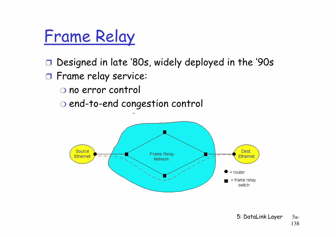
r Designed in late ‘80s, widely deployed in the ‘90s
r Frame relay service:
m no error control
m end-to-end congestion control
5: DataLink Layer 5a-
138

Frame Relay (more)r Designed to interconnect corporate customer LANs
m typically permanent VC’s: “pipe” carrying aggregate traffic between two routers
m switched VC’s: as in ATM
r corporate customer leases FR service from public Frame Relay network (e.g., Sprint, ATT)
5: DataLink Layer 5a-
139
corporate customer leases FR service from public Frame Relay network (e.g., Sprint, ATT)
Frame Relay (more)
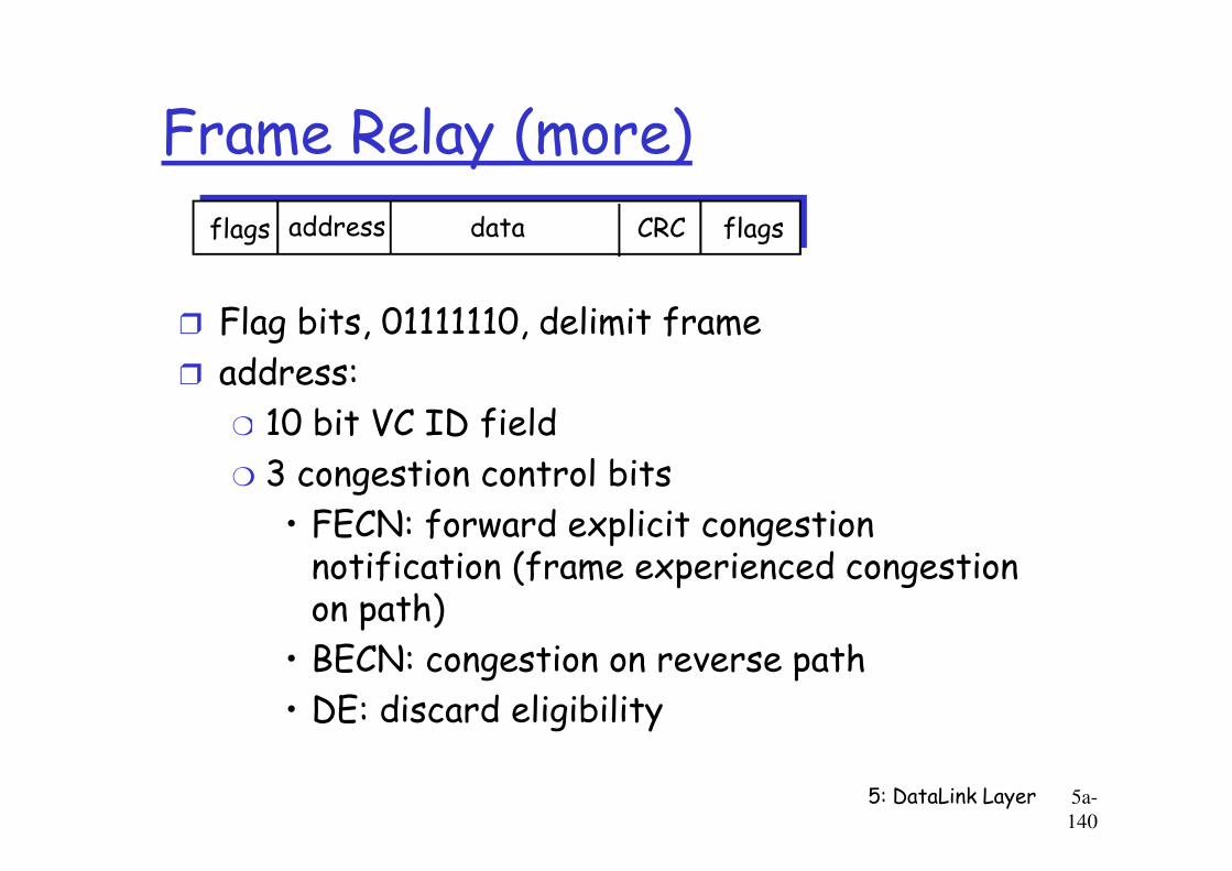
r Flag bits, 01111110, delimit frame
r address:
m 10 bit VC ID field
addressflags data CRC flags
5: DataLink Layer 5a-
140
m 10 bit VC ID field
m 3 congestion control bits
• FECN: forward explicit congestion notification (frame experienced congestion on path)
• BECN: congestion on reverse path
• DE: discard eligibility
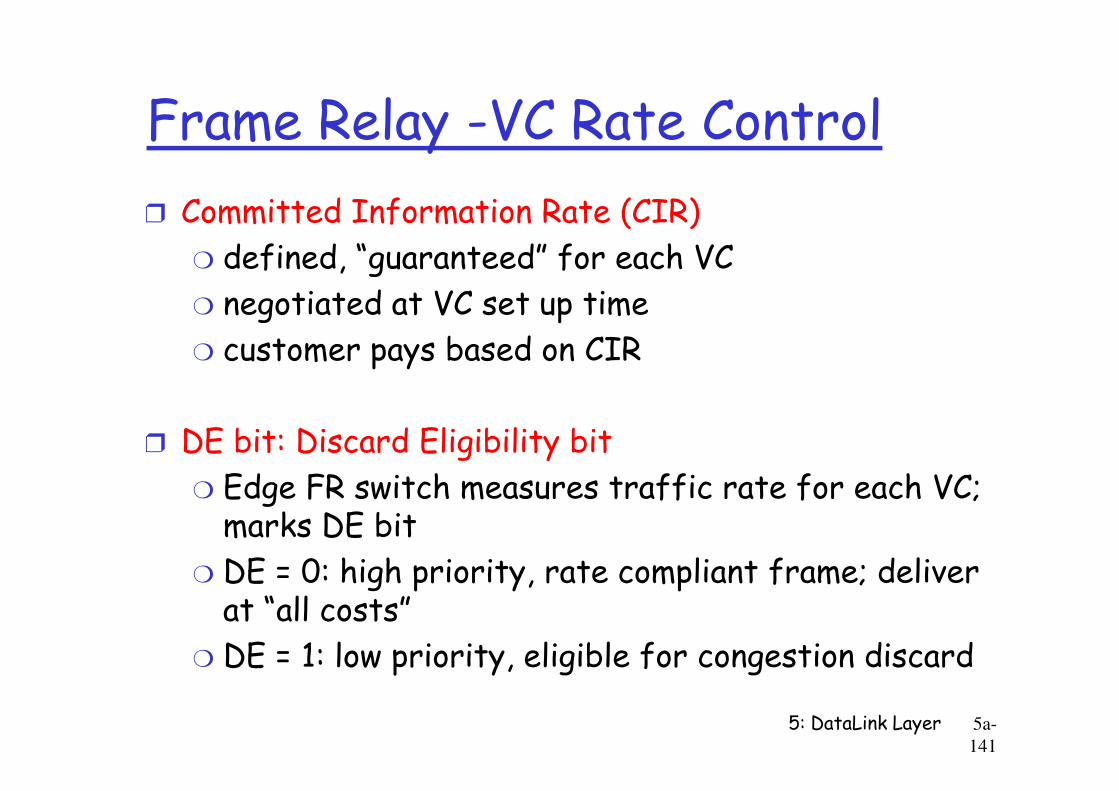
Frame Relay -VC Rate Control
r Committed Information Rate (CIR)
m defined, “guaranteed” for each VC
m negotiated at VC set up time
m customer pays based on CIR
5: DataLink Layer 5a-
141
r DE bit: Discard Eligibility bit
m Edge FR switch measures traffic rate for each VC; marks DE bit
m DE = 0: high priority, rate compliant frame; deliver at “all costs”
m DE = 1: low priority, eligible for congestion discard
Frame Relay - CIR & Frame Marking
r Access Rate: rate R of the access link between source router (customer) and edge FR switch(provider); 64Kbps < R < 1,544Kbps
r Typically, many VCs (one per destination router) multiplexed on the same access trunk; each VC has
5: DataLink Layer 5a-
142
multiplexed on the same access trunk; each VC has own CIR
r Edge FR switch measures traffic rate for each VC; it marks (i.e. DE = 1) frames which exceed CIR (these may be later dropped)
r Internet’s more recent differentiated serviceuses similar ideas
Chapter 5: Summary
r principles behind data link layer services:m error detection, correction
m sharing a broadcast channel: multiple access
m link layer addressing, ARP
r link layer technologies: Ethernet, hubs, bridges, switches,IEEE 802.11 LANs, PPP,
5: DataLink Layer 5a-
143
link layer technologies: Ethernet, hubs, bridges, switches,IEEE 802.11 LANs, PPP, ATM, Frame Relay
r journey down the protocol stack now OVER!m next stops: multimedia, security, network management