Lighting CSE167: Computer Graphics Instructor: Steve Rotenberg UCSD, Fall 2005.
date post
22-Dec-2015Category
view
223download
5
Lighting
CSE167: Computer Graphics
Instructor: Steve Rotenberg
UCSD, Fall 2006
Triangle Rendering
The main stages in the traditional graphics pipeline are: Transform Lighting Clipping / Culling Scan Conversion Pixel Rendering

Transform, Clip, Scan Convert
The transformation, clipping/culling, and scan conversion processes provide us a way to take a 3D object defined in it’s object space and generate a 2D image of pixels
If each vertex has a color, that color gets smoothly interpolated across the triangle giving us a way to generate full color images
Lighting is essentially the process of automatically assigning colors to the vertices based on their position/orientation in the world relative to lights and other objects
Lighting Today, we will mainly focus on vertex lighting Each vertex goes through a lighting process which
determines its final color This color value is then interpolated across the triangle
in the scan conversion process Usually, each vertex has some sort of initial color
assigned to it, which defines what color it would be if well lit by a uniform white light
This initial color is then modified based on the position and normal of the vertex in relation to lights placed in the scene (in other words, a grey vertex dimly lit by red lights will appear dark red…)
In GL, you pass in the ‘unlit’ color through glColor3f(). It will then compute the ‘lit’ color, which gets interpolated in the scan conversion process
Normal Transformations
Lighting requires accurate measurement of distances and angles, so we want to compute lighting in a regular 3D space (i.e., not 4D un-normalized view space, or 2.5D device space…)
This leaves object space, world space, or camera space as our most natural options
To light in object space, we would have to transform the lights from world space into each object’s space
If we are applying shears or non-uniform scales to our object, this will distort the object which will mean that object space isn’t actually a legitimate place to do lighting
Lighting in world space would be fine, but it would require transforming the object into world space, which is a step that we usually avoid explicitly doing
Therefore, it makes good sense to light in camera space, as we will probably want to perform clipping & some culling in this space as well
GL does it’s lighting in camera space, which means that we must transform normals into camera space in addition to the vertex positions
Normal Transformations
Remember that when we transform a normal, we don’t want to apply the translation portion of the matrix (the right hand column)
A normal transforms as a direction, not a position, and so we expand it into its 4D format as:
0zyx nnn
Direction Vector Transformation
zzzyzxz
yzyyyxy
xzxyxxx
z
y
x
zzzz
yyyy
xxxx
cnbnann
cnbnann
cnbnann
n
n
n
dcba
dcba
dcba
01000
nMn
Normal Transformations
It’s actually worse than that… Let’s say we take the 3 vertices of a triangle and
compute the normal, then we transform the 3 vertices and the normal
If the transformation contains any shear or non-uniform scaling, then it is possible that the transformed normal will no longer be perpendicular to the transformed triangle itself
To fix this, we should actually transform the normal by the inverse transpose of the matrix, or M-1T
The transformed normals will also not be unit length any more, so they must also be renormalized before lighting
Normal Transformations
In other words, if we have non-rigid transformations, we need to compute a matrix inverse once, and then renormalize every normal to properly transform the normals
This is expensive, so should only be done when necessary
The good news is that most of the time, we tend to use rigid transformations in computer graphics (transformations that are built up purely from rotations and translations) and for a rigid matrix, M-1T=M
Another good piece of news is that we only need to transform the normals in to world or camera space, and don’t need to project them or compute a perspective division
Normal Transformations
If we want to compute lighting in camera space, we need to first transform the vertices & normals into camera space:
*
*
1*
1
n
nn
nMn
vMv
WCM
T
0
1
zyx
zyx
nnn
vvv
n
v
Lighting
Whether we are computing lighting per vertex or lighting per pixel, the basic process is the same
In either case, we are computing the lighting at some position v with some normal n
Material Colors
Objects have an inherent material color which is the color that the object reflects
The material gets its color because the reflectivity varies with the wavelength of light
In CG, we usually don’t represent color as a continuous spectrum. Instead, we just represent it is a combination of red, green, and blue
Obviously, an object can’t reflect more light than it receives, so at best, it could reflect 100% of the light in all wavelengths (thus appearing bright white)
A more realistic white object might reflect perhaps 95% of the light, so we would say that its actual material color is (0.95, 0.95, 0.95)
We will assume that material colors are limited from 0.0 to 1.0 in red, green, and blue (or more realistically from 0.0 to 0.98 or so)

Light Color
However, if we are looking at a white piece of paper under uniform light, we can always turn more lights on, and get more light to reflect off of the paper
There is no upper limit to the intensity of light If we want to represent a light intensity (light
color), we can store it as red, green, and blue values ranging from 0.0 to an arbitrarily high value
In other words, a bright white light bulb might have an color of (10, 10, 10)
Color & Intensity
We need to make a distinction between material color and light color
Material colors represent the proportion of light reflected Light colors represent the actual intensity of a beam of light We never actually perceive the inherent material color, all we see is
the light reflected off of a material If we shine a red light on a grey surface, the object appears dark red
because it is reflecting beams of dark red light
I will use m to represent a material color and c to represent an actual light color
Exposure The monitor has an upper limit to the brightness it can display If light intensity has no upper limit, then how do we determine what the value of
‘white’ is? This relates to the issue of white balance and exposure control The human eye (and digital cameras) will adjust their internal exposure settings to
normalize the appearance of white In other words, if we are in a moderately lit room, the light color (0.5, 0.5, 0.5) might
appear as white, but when we go outside, our eye adjusts its exposure so that (10, 10, 10) looks white
Ideally, we would have some sort of virtual exposure control There are various advanced rendering techniques that handle the issues of color and
exposure in fairly complex ways
For today, we will just assume that a light intensity of (1,1,1) is white, and any light intensity values above 1.0 will simply get clamped to 1.0 before storing the color in the actual pixel
Reflectivity
A white sheet of paper might reflect 95% of the light that shines on it
An average mirror might reflect 95% of the light that shines on it
Yet, these two things look completely different, because they reflect light in different directions
We say that the paper is a diffuse reflector, whereas the mirror is a specular reflector
Diffuse Reflection
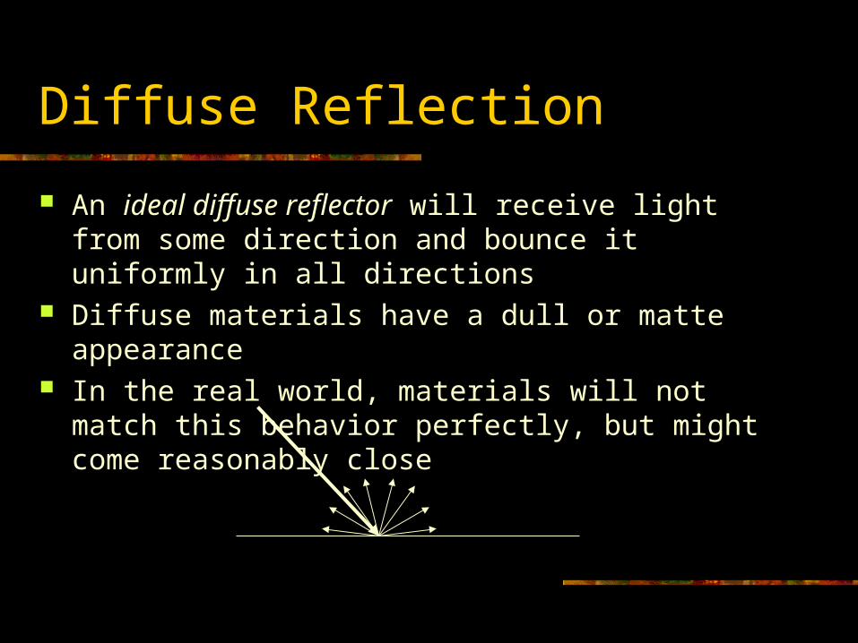
An ideal diffuse reflector will receive light from some direction and bounce it uniformly in all directions
Diffuse materials have a dull or matte appearance In the real world, materials will not match this behavior
perfectly, but might come reasonably close
Specular Reflection
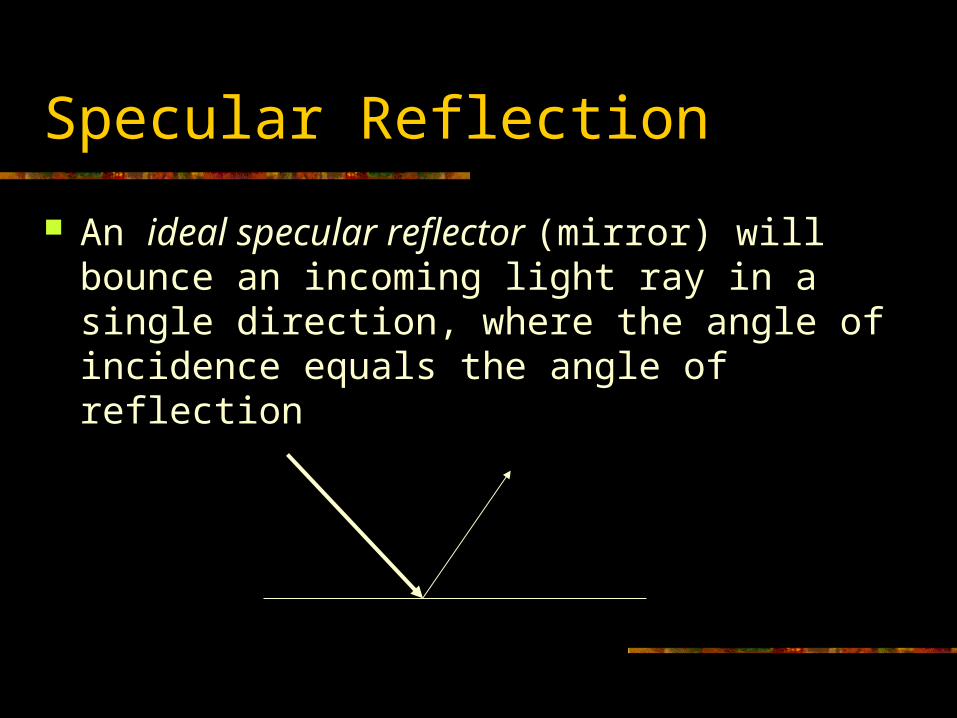
An ideal specular reflector (mirror) will bounce an incoming light ray in a single direction, where the angle of incidence equals the angle of reflection

Specular (Glossy) Reflection
Sometimes, a material behaves in a specular way, but not quite perfect like a mirror (like an unpolished metal surface)
In CG, this is sometimes referred to as glossy reflection Glossy materials look shiny and will show specular
highlights

Diffuse/Specular Reflection
Many materials have a mixture of diffuse and specular behavior
Plastics are a common example of this, as they tend to have an overall diffuse behavior, but still will catch highlights
Real Reflector
Materials in the real world might have fairly complex reflection distributions that vary based on the angle on the incoming light
Modeling these properties correctly is a very important part of photoreal rendering, and we will talk more about this in later lectures
For today, we will allow materials to have a mixture of ideal diffuse and glossy properties

Diffuse Reflection
At first, we will consider a purely diffuse surface that reflects light equally in all directions
The light reflected is proportional to the incident light (the material color determines the proportion)
Lets assume we have a beam of parallel light rays shining on the surface
The area of the surface covered by the beam will vary based on the angle between the incident beam and the surface normal
The larger this area, the less incident light per area In other words, the object will appear darker as the
normal turns away from the light
Diffuse Reflection
n
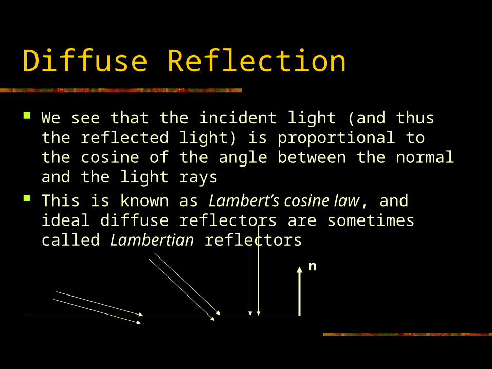
We see that the incident light (and thus the reflected light) is proportional to the cosine of the angle between the normal and the light rays
This is known as Lambert’s cosine law, and ideal diffuse reflectors are sometimes called Lambertian reflectors

Diffuse Reflection
We will use the vector l to represent the unit length vector that points to the light source
nl
lncmc lgtdif *
clgt
mdif
Component Multiplication
Note: I use the * symbol to represent component-by-component multiplication for vectors
zzyyxx
zyx
zyx
bababa
bbb
aaa
ba
b
a
*
Directional Light
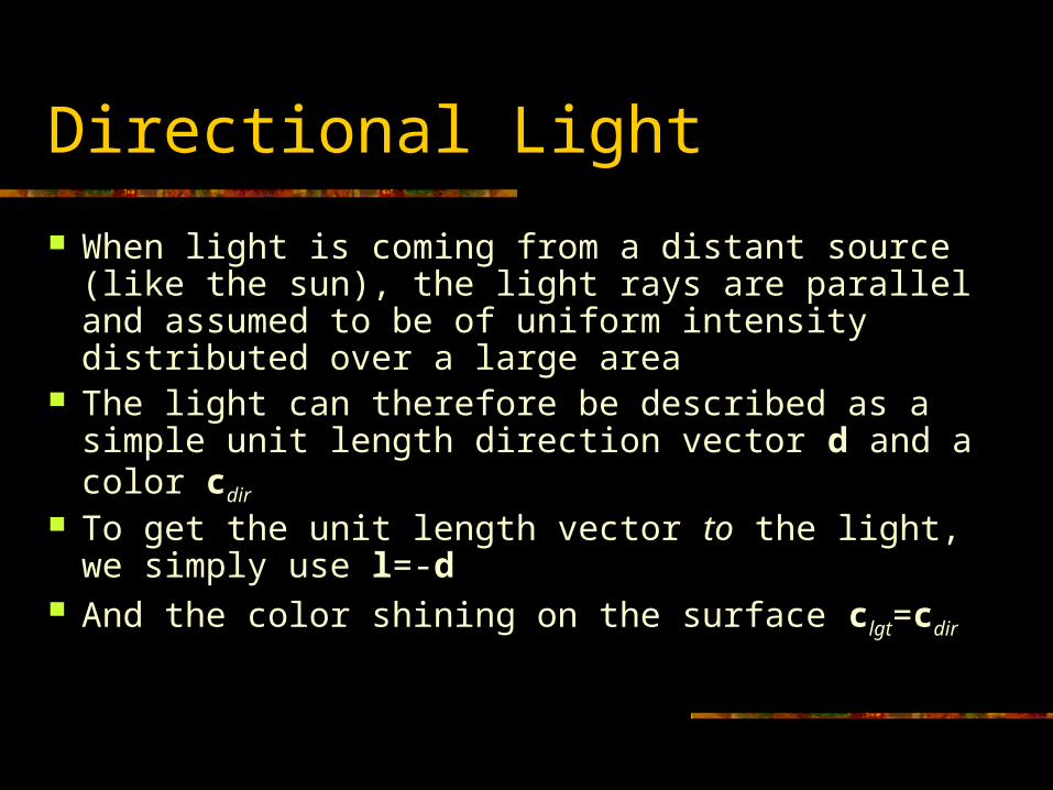
When light is coming from a distant source (like the sun), the light rays are parallel and assumed to be of uniform intensity distributed over a large area
The light can therefore be described as a simple unit length direction vector d and a color cdir
To get the unit length vector to the light, we simply use l=-d
And the color shining on the surface clgt=cdir
Point Lights
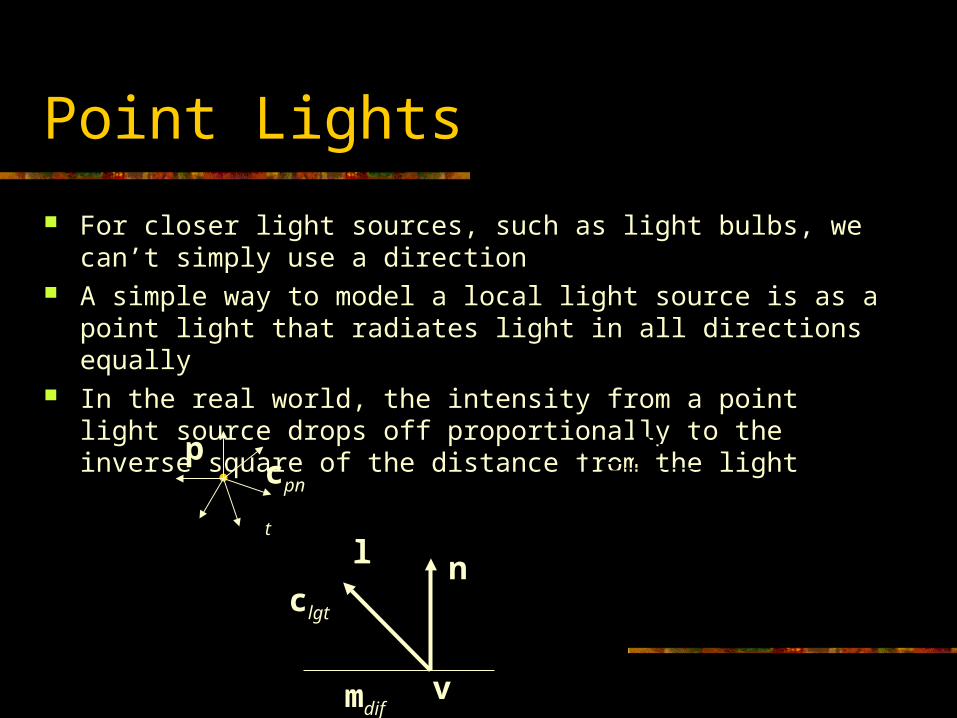
For closer light sources, such as light bulbs, we can’t simply use a direction
A simple way to model a local light source is as a point light that radiates light in all directions equally
In the real world, the intensity from a point light source drops off proportionally to the inverse square of the distance from the light
nl2
vp
cc
vp
vpl
pntlgtclgt
mdifv
pcpnt
Attenuation
Sometimes, it is desirable to modify the inverse square falloff behavior of point lights
A common (although not physically accurate) model for the distance attenuation is:
vp
cc
dwhere
dkdkk qlc
pntlgt
2

Incident Light
To compute a particular light’s contribution to the total vertex/pixel color, we start by computing the color of the incident light
The incident light color clgt represents the actual light reaching the surface in question
For a point light, for example, the actual incident light is going to be the color of the source, but will be attenuated based on the inverse square law (or some variation of it)
We also need to know the incident light direction. This is represented by the unit length vector l (that’s supposed to be a lower case L)
Computing the incident light color & direction is pretty straightforward, but will vary from light type to light type
Multiple Lights
Light behaves in a purely additive way, so as we add more lights to the scene, we can simply add up the total light contribution
OK, well actually, in some very specific cases, light can interfere with other light and effectively behave in a subtractive way as well, but this is limited to very special cases (like the coloration of soap bubbles…)
iilgtdif lncmc *

Ambient Light
In the real world, light gets bounced all around the environment and may shine on a surface from every direction
Modeling accurate light bouncing is the goal of photoreal rendering, but this is very complex and expensive to compute
A much simpler way to model all of the background reflected light is to assume that it is just some constant color shining from every direction equally
This is referred to as ambient light and can be added as a simple extra term in our lighting equation:
Usually, mamb is set to equal mdif
iilgtdifambamb lncmcmc **

Specular Highlights
There are a variety of ways to achieve specular highlights on surfaces
For now, we will look at a relatively simple method known as the Blinn lighting model
We assume that the basic material is specularly reflective (like a metal), but with a rough surface that causes the actual normals to vary at a small scale
We will say that the surface at a microscopic scale is actually composed of many tiny microfacets, which are arranged in a more or less random fashion
Specular Highlights
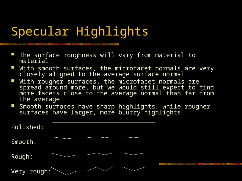
The surface roughness will vary from material to material With smooth surfaces, the microfacet normals are very closely
aligned to the average surface normal With rougher surfaces, the microfacet normals are spread around
more, but we would still expect to find more facets close to the average normal than far from the average
Smooth surfaces have sharp highlights, while rougher surfaces have larger, more blurry highlights
Polished:
Smooth:
Rough:
Very rough:
Specular Highlights
n
lclgt
mdif
eh
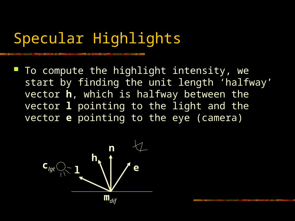
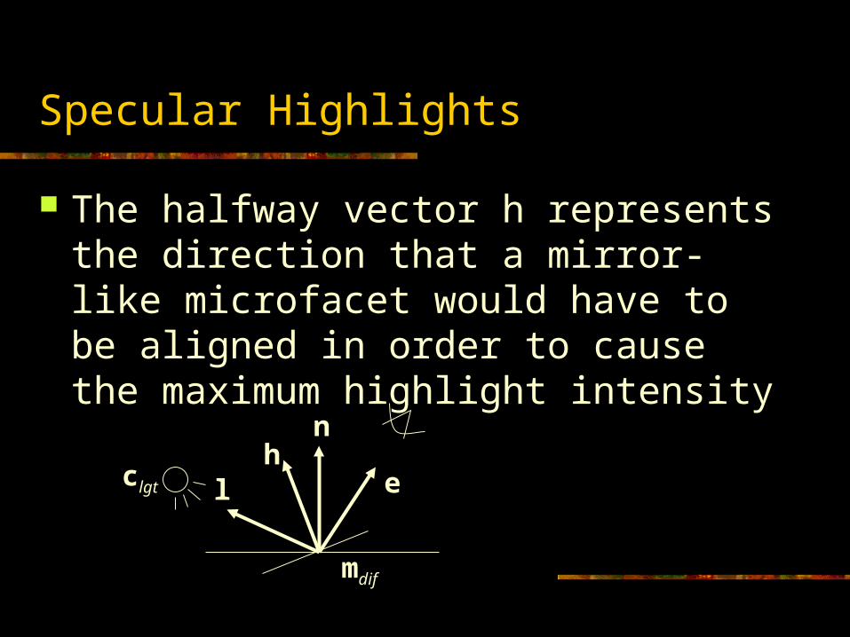
To compute the highlight intensity, we start by finding the unit length ‘halfway’ vector h, which is halfway between the vector l pointing to the light and the vector e pointing to the eye (camera)
le
leh
Specular Highlights
The halfway vector h represents the direction that a mirror-like microfacet would have to be aligned in order to cause the maximum highlight intensity
n
lclgt
mdif
eh

Specular Highlights
The microfacet normals will point more or less in the same direction as the average surface normal, so the further that h is from n, the less likely we would expect the microfacets to align
In other words, we want some sort of rule that causes highlights to increase in brightness in areas where h gets closer to n
The Blinn lighting model uses the following value for the highlight intensity:
Where s is the shininess or specular exponent
sf nh
Specular Highlights
h·n will be 1 when h and n line up exactly and will drop off to 0 as they approach 90 degrees apart
Raising this value to an exponent retains the behavior at 0 and 90 degrees, but the dropoff increases faster as s gets higher, thus causing the highlight to get narrower
sf nh
Specular Highlights
To account for highlights, we simply add an additional contribution to our total lighting equation
Each light will potentially contribute highlights, so it is included in our loop over the lights:
This is essentially the Blinn lighting model. It appears in a few slightly different forms and in a wide variety of notations…
siilgtspeciilgtdifambamb hncmlncmcmc ***
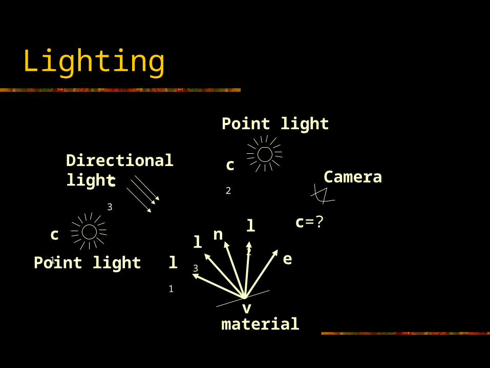
Lighting
n
l1e
l2l3
material
Point light
Directional light
Point light
c1
c3
c2
c=?
v
Camera

Lighting Models
There are many lighting models out there Some of the classic ones are:
Blinn Phong Lambert Cook-Torrance
There are many more advanced models used in modern photoreal rendering. We will take a brief look at these later…
Gouraud Shading
Back in the ‘old days’, triangles were lit as flat surfaces with a single normal
In 1971, Henri Gouraud suggested that computing the lighting at the verts and then interpolating the color across the triangle could simulate the appearance of smooth surfaces
This technique is called Gouraud shading and is the default behavior for most hardware renderers
Phong Shading
Computing lighting at the vertices is fast, but has several limitations
For high quality rendering, it is much more common to compute lighting per pixel
In order to render triangles as smooth surfaces, the most common technique is to interpolate the normals across the triangle and then use the interpolated normal (and position) to compute the per-pixel lighting
This is known as Phong shading or Phong interpolation (not to be confused with the Phong lighting model)
Modern graphics hardware can perform Phong shading through the use of pixel shaders
Flat vs. Curved Triangles
We see that a triangle can represent a flat surface or approximate a small curved surface
Even if we want a triangle to be flat (like on the face of a cube), we should still compute the lighting at each vertex
The reason is that the resulting color might be different due to inverse square attenuation, specular lighting, or other reasons
In other words, we don’t really need to make a distinction between flat and curved triangles, as the lighting is computed the same for each (only the normals vary)
Advanced Lighting
Shadows Accurate reflection models Procedural shaders Global Illumination Volumetric effects (fog, translucency…) Lens imperfections Exposure (& dynamic range)