Ion Pumps Control Unit - Accelerator Division … Unit Model 529-5001R001 vacuum technologies Ion...
24
87-900-128-01 (C) JUNE 2008 (GB) INSTRUCTION MANUAL Ion Pumps Control Unit Model 529-5001R001 vacuum technologies
Transcript of Ion Pumps Control Unit - Accelerator Division … Unit Model 529-5001R001 vacuum technologies Ion...
87-900-128-01 (C)JUNE 2008
(GB) INSTRUCTION MANUAL
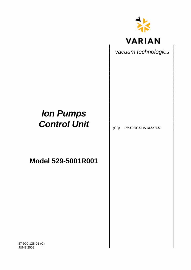
Ion PumpsControl Unit
Model 529-5001R001
vacuum technologies
Ion PumpsControl Unit
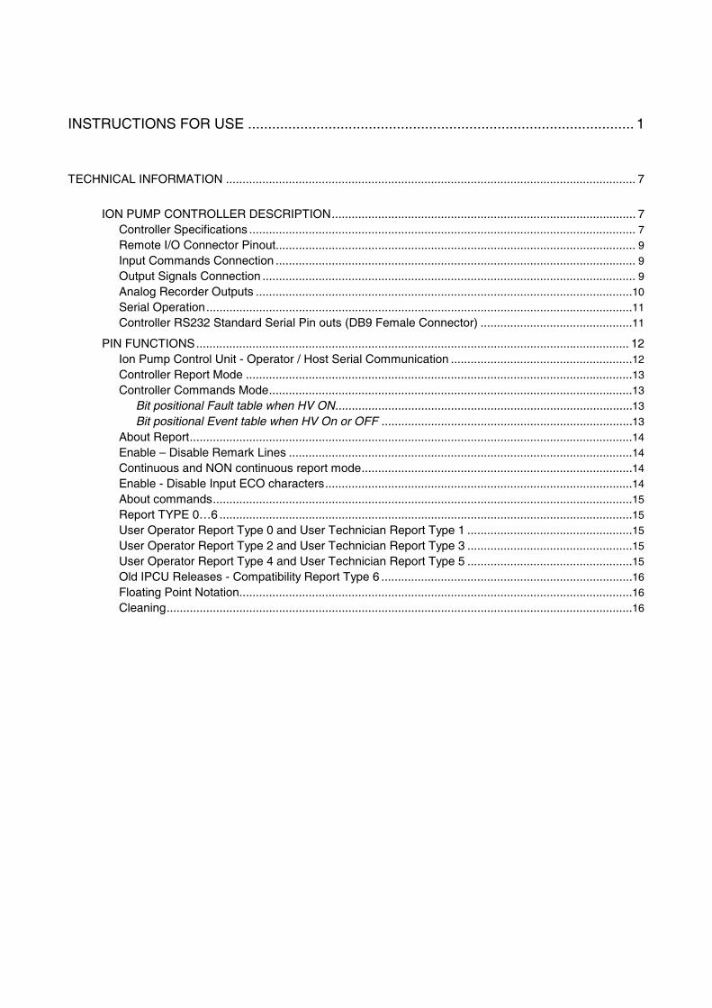
INSTRUCTIONS FOR USE ................................................................................................ 1
TECHNICAL INFORMATION ............................................................................................................................ 7
ION PUMP CONTROLLER DESCRIPTION............................................................................................ 7Controller Specifications ..................................................................................................................... 7Remote I/O Connector Pinout............................................................................................................. 9Input Commands Connection ............................................................................................................. 9Output Signals Connection ................................................................................................................. 9Analog Recorder Outputs ..................................................................................................................10Serial Operation.................................................................................................................................11Controller RS232 Standard Serial Pin outs (DB9 Female Connector) ..............................................11
PIN FUNCTIONS................................................................................................................................... 12Ion Pump Control Unit - Operator / Host Serial Communication .......................................................12Controller Report Mode .....................................................................................................................13Controller Commands Mode..............................................................................................................13
Bit positional Fault table when HV ON..........................................................................................13
Bit positional Event table when HV On or OFF ............................................................................13
About Report......................................................................................................................................14Enable – Disable Remark Lines ........................................................................................................14Continuous and NON continuous report mode..................................................................................14Enable - Disable Input ECO characters.............................................................................................14About commands...............................................................................................................................15Report TYPE 0…6 .............................................................................................................................15User Operator Report Type 0 and User Technician Report Type 1 ..................................................15User Operator Report Type 2 and User Technician Report Type 3 ..................................................15User Operator Report Type 4 and User Technician Report Type 5 ..................................................15Old IPCU Releases - Compatibility Report Type 6 ............................................................................16Floating Point Notation.......................................................................................................................16Cleaning.............................................................................................................................................16
INSTRUCTIONS FOR USE
1/16 87-900-128-01 (C)
GENERAL INFORMATION
This equipment is destined for use by professionals.The user should read this instruction manual and anyother additional information supplied by Varian beforeoperating the equipment. Varian will not be heldresponsible for any events occurring due to non-compliance, even partial, with these instructions,improper use by untrained persons, non-authorisedinterference with the equipment or any action contraryto that provided for by specific national standards.The following paragraphs contain all the informationnecessary to guarantee the safety of the operator whenusing the equipment. Detailed information is supplied inthe appendix "Technical Information".
This manual uses the following standard protocol:
!The warning messages are for attracting the attentionof the operator to a particular procedure or practicewhich, if not followed correctly, could lead to seriousinjury.
CAUTION!
The caution messages are displayed beforeprocedures which, if not followed, could cause damageto the equipment.
NOTE
The notes contain important information taken from thetext.
CONTROLLER DESCRIPTION
Varian’s controller is an ion pumps controller.It can drive up to 2 Ion Pumps simultaneously andindependently. The controller is designed to give theHV to the Ion Pumps when it is connected to the Mainssupply (Max. Output Voltage = 5000 Vdc). (See theparagraph “Technical Informations” for details).
Varian’ s Ion Pump controller can be driven inLocal/Remote I/O operating mode or in the Serial modevia the RS232 port. The selection of the operatingmode is done by means of the SERIAL/LOCAL-RemoteI/O switch on the controller front panel.
In the LOCAL-REMOTE I/O mode, all the commandsare given by the front panel or by the connections tothe DB25 “REMOTE” connector on the rear panel.
The pump operating conditions data are anywayavailable on the serial connection. In the SERIALmode, all the commands are given through the serialconnection and all the pump operating conditions dataare available on the serial connection.
STORAGE
When transporting and storing the controller, thefollowing environmental requirements should not beexceeded:− temperature: from -20° to +70 °C− relative humidity: 0 - 95% (non-condensing)
PREPARATION FOR INSTALLATION
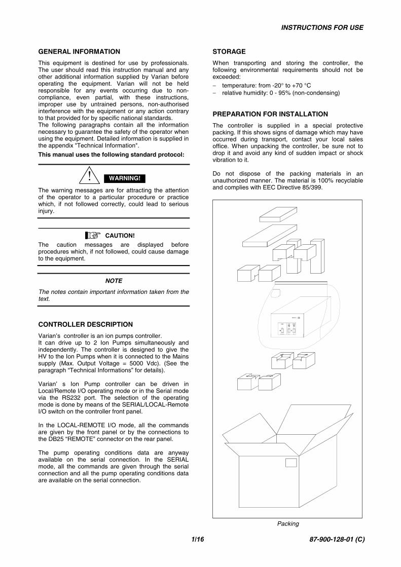
The controller is supplied in a special protectivepacking. If this shows signs of damage which may haveoccurred during transport, contact your local salesoffice. When unpacking the controller, be sure not todrop it and avoid any kind of sudden impact or shockvibration to it.
Do not dispose of the packing materials in anunauthorized manner. The material is 100% recyclableand complies with EEC Directive 85/399.
SERIAL
LOCAL / REM I/O OFF / O
ON / I ON / I
MODE GUN
OFF / O
TARGET
MAINS ON
Packing
WARNING!
INSTRUCTIONS FOR USE
2/16 87-900-128-01 (C)
INSTALLATION
!High voltage developed in the controller can causesevere injury or death. Before servicing the unit,disconnect the power cable.
CAUTION!
The Controller must be positioned so that free air canflow through the holes of the top and the side cover.Do not install or use the controller in an environmentexposed to atmospheric agents (rain, snow, ice), dust,aggressive gases, or in explosive environments orthose with a high fire risk.
!The controller must be installed in a way that allows aneasy interruption of the line voltage (disconnection ofthe line plug or interruption on the rack general lineswitch).
During operation, the following environmentalconditions must be respected:
• temperature: from +5 °C to +40 °C• relative humidity: 0 - 95% (non-condensing)
To connect the controller to the pump use the specificcables supplied.
See the appendix “Technical Information” for detailedinformation about the above mentioned and the otherconnections.
USE
This paragraph describes the fundamental operatingprocedures. Detailed information and operatingprocedures that involve optional connections or optionsare supplied in the paragraph “USE” of the appendix“Technical Information”.
Make all vacuum manifold and electrical connectionsand refer to the connected pump instruction manualprior to operating the controller.
!To avoid injury to personnel and damage to theequipment, if the pump is laying on a table make sure itis steady. Never operate the pump if the pump inlet isnot connected to the system or blanked off.
WARNING!
WARNING!
WARNING!
INSTRUCTIONS FOR USE
3/16 87-900-128-01 (C)
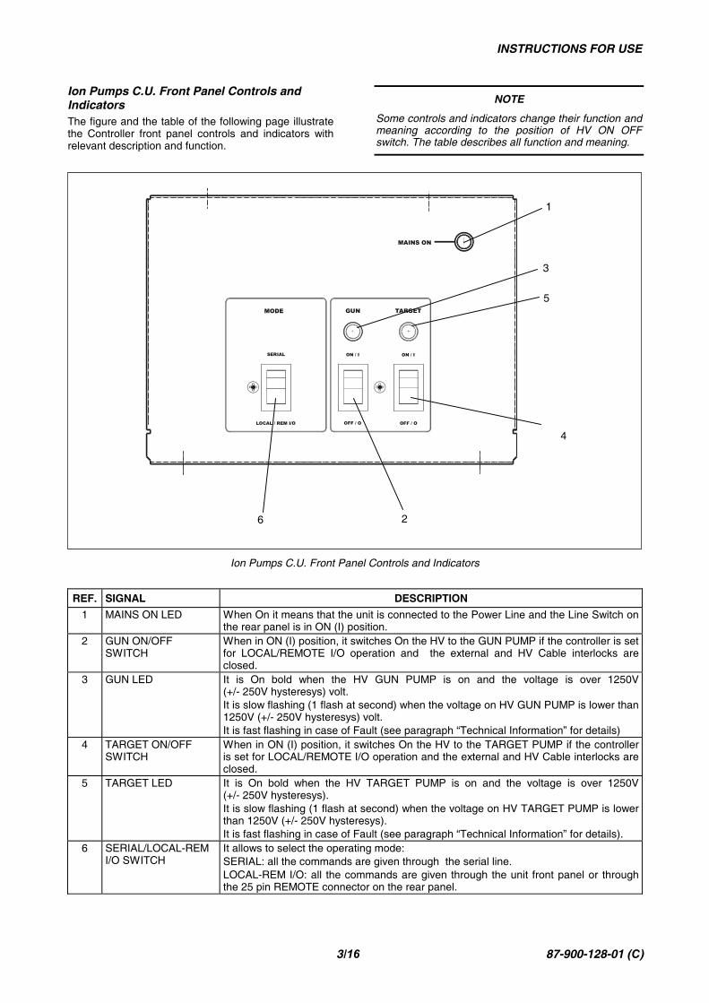
Ion Pumps C.U. Front Panel Controls andIndicatorsThe figure and the table of the following page illustratethe Controller front panel controls and indicators withrelevant description and function.
NOTE
Some controls and indicators change their function andmeaning according to the position of HV ON OFFswitch. The table describes all function and meaning.
Ion Pumps C.U. Front Panel Controls and Indicators
REF. SIGNAL DESCRIPTION
1 MAINS ON LED When On it means that the unit is connected to the Power Line and the Line Switch onthe rear panel is in ON (I) position.
2 GUN ON/OFFSWITCH
When in ON (I) position, it switches On the HV to the GUN PUMP if the controller is setfor LOCAL/REMOTE I/O operation and the external and HV Cable interlocks areclosed.
3 GUN LED It is On bold when the HV GUN PUMP is on and the voltage is over 1250V(+/- 250V hysteresys) volt.It is slow flashing (1 flash at second) when the voltage on HV GUN PUMP is lower than1250V (+/- 250V hysteresys) volt.It is fast flashing in case of Fault (see paragraph “Technical Information” for details)
4 TARGET ON/OFFSWITCH
When in ON (I) position, it switches On the HV to the TARGET PUMP if the controlleris set for LOCAL/REMOTE I/O operation and the external and HV Cable interlocks areclosed.
5 TARGET LED It is On bold when the HV TARGET PUMP is on and the voltage is over 1250V(+/- 250V hysteresys).It is slow flashing (1 flash at second) when the voltage on HV TARGET PUMP is lowerthan 1250V (+/- 250V hysteresys).It is fast flashing in case of Fault (see paragraph “Technical Information” for details).
6 SERIAL/LOCAL-REMI/O SWITCH
It allows to select the operating mode:SERIAL: all the commands are given through the serial line.LOCAL-REM I/O: all the commands are given through the unit front panel or throughthe 25 pin REMOTE connector on the rear panel.
1
4
5
3
26
SERIAL
LOCAL / REM I/O OFF / O OFF / O
ON / I ON / I
MODE GUN TARGET
MAINS ON
INSTRUCTIONS FOR USE
4/16 87-900-128-01 (C)
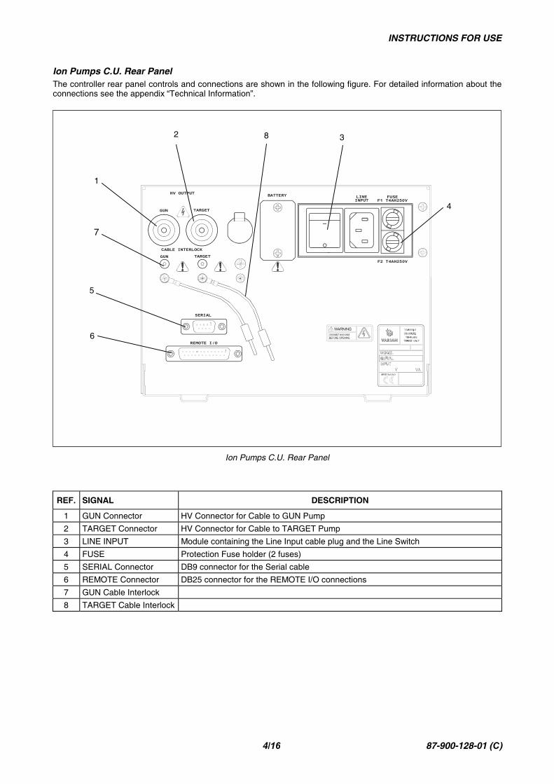
Ion Pumps C.U. Rear PanelThe controller rear panel controls and connections are shown in the following figure. For detailed information about theconnections see the appendix “Technical Information”.
Ion Pumps C.U. Rear Panel
REF. SIGNAL DESCRIPTION
1 GUN Connector HV Connector for Cable to GUN Pump
2 TARGET Connector HV Connector for Cable to TARGET Pump
3 LINE INPUT Module containing the Line Input cable plug and the Line Switch
4 FUSE Protection Fuse holder (2 fuses)
5 SERIAL Connector DB9 connector for the Serial cable
6 REMOTE Connector DB25 connector for the REMOTE I/O connections
7 GUN Cable Interlock
8 TARGET Cable Interlock
1
2 3
4
5
6
7
8
INSTRUCTIONS FOR USE
5/16 87-900-128-01 (C)
USAGE
This paragraph gives a general information on the useof the controller. For details refer to the “TechnicalInformation” paragraph. When the controller is pluggedto the Power Line and the Line Switch on the rear panelis ON (I), it is able to operate with its full set of features:
• 2 independent HV channels• +5000 Vdc maximum output Voltage• 40W maximum output Power for channel 1• 80W maximum output Power for channel 2• 30 mA maximum output current (short circuit
condition) for gun• 50 mA maximum output current (short circuit
condition) for target• LOCAL-REMOTE I/O/SERIAL operating mode• START/PROTECT operation
OPERATING MODES
Power Line supply
LOCAL-REMOTE I/O Operation
NOTE
The 2 HV switches on the front panel and the 2 HVOn/Off inputs on the DB25 “Remote” connector on therear panel are functionally in series.
HV On/Off gun by front panel:
Connect together pin 8 and pin 21 of the remote I/Oconnector and move the gun switch on the front panel.
HV On/Off target by front panel:
Connect together pin 9 and pin 22 of the Remote I/Oconnector and move the gun switch on the front panel.
The correspondent HV cable Interlocks must be closed.
When the HV is ON, the corresponding HV LED on thefront panel, will be ON.
!Auto – start function: ON. In case of power loss withGUN and/or TARGET ON, at next power-on the unit willswitch on the HV (previously on) automatically.
Auto power-on function. With front panel switches inON position and remote I/O jumpers, the unit will switchon both channels as soon as the mains is on.
NOTE
If the connection between the IPCU and the pump isdone by means of an HV Cable with Safety Interlock,the cable must be connected to the pump F/T and thesmall “banana” connector on the cable controller sidemust be inserted in the corresponding “HV CableInterlock” plug on the unit rear panel in order to be ableto switch on the HV.
If the connection is done with a single pole HV Cablewithout the Safety Interlock, ensure that the jumperprovided on the unit rear panel is inserted in the “HVCable Interlock” plug.
SERIAL Operation
NOTE
The SERIAL is set in order to operate by connectingthe controller to an external PC that uses the “HYPERTERMINAL” or equivalent program (for example aproprietary user program) running under WindowsOperating System or other. To operate in serial mode,connect the serial port to the controller “Serial”connector on the rear panel, run the Windows “HYPERTERMINAL” program on the PC with the followingdefault settings:
• COM1• 9600 baud• No parity• 8 data bits• 1 stop bit
This way of operation will allow to verify thefunctionality of the unit in the “SERIAL” operatingmode, give the commands and get all the operatingdata.
NOTE
In the serial operation, depending on the userenvironment, the O.S. used must have real timecapability.
See the “Technical Information” paragraph for details.
START/PROTECT OperationThe controller can operate in two modes: Start andProtect.
In Start, the 2 output channels can provide all theoutput power regardless of the pump condition up tothe short circuit condition.This operating mode must be used to start the pump athigh pressure.
In Protect, the controller limits the output current andswitches off the HV when the current exceeds thethreshold value (8 mA for 40W channel and 16 mA for80W channel) for more than 2 seconds.The default mode is “Start” mode.
WARNING!

INSTRUCTIONS FOR USE
6/16 87-900-128-01 (C)
ERROR MESSAGES
On Front PanelDuring the controller operation, if an error condition isdetected, the HV LEDs on the front panel will give theindication:
GUN, TARGETLEDS ON: Normal Operation = HV ON
Led GUN, TARGET flashing: error condition:1 flash every 4 seconds = Interlock HV cable2 flashes every 4 seconds = remote Interlock3 flashes every 4 seconds = HV Over voltage(This Fault doesn’ t switch-off the HV)4 flashes every 4 seconds = error inside ADC5 flashes every 4 seconds = overcurrenton HV (short circuit)6 flashes every 4 seconds = theLocal/Remote switch was moved with HVON7 flashes every 4 seconds = overtemperature inside unit8 flashes every 4 seconds = overcurrent inProtect (8 mA for 40W channel and 16 mAfor 80W channel)9 flashes every 4 seconds = HV Undervoltage
In Local-Remote I/O mode, the Reset of the Faultcondition is accomplished by switching to Off (0) thefront panel switch of the corresponding channel.
In Serial mode, the Reset of the Fault condition isaccomplished by sending the “F0n” command by thecomputer.
NOTE
If one of the following conditions happens while the HVof the channel is On, the output of the channel isimmediately set to Off, the LED on the front panelindicates the corresponding Fault condition and theFault information is sent to the Serial output.
Auto retries function. If an under-voltage fail occur,for instance on GUN while both channels were on theunit do:• Distinguish between a real low voltage and thermal
switch (TS) intervention.• Keep the Target ON, GUN switched off, no fail
condition activated (fault relay remains open),current output recorder goes to 5 V.
• Start time out cont (30 min.)• If the TS is restorted before the time out the gun
goes on agin and time out count resetted.• If the TS is not restorted after the time out the
IPCU goes into fail and both GUN and TARGETare off.
• On “Remote” connector on Rear Panel.• “Fault” output: N.C. contact (idle state) =• The contact is Open in “Fault” condition (relay Off)• The contact is Close in normal condition (relay On)
• “HV 1,2” output: N.O. contact (idle state) =• The contact is Open with HV in Off state (relay Off)• The contact is Closed with HV in On state
(relay On)
• “HV 1,2” output current set point: N.O. contact(idle state) =
• The contact is Open with output current value isbelow the current set point (relay Off)
• The contact is Closed with output current valueabove the current set point (relay On)
DISPOSAL
Meaning of the "WEEE" logo found in labelsThe following symbol is applied in accordance with theEC WEEE (Waste Electrical and Electronic Equipment)Directive.This symbol (valid only in countries of the EuropeanCommunity) indicates that the product it applies tomust NOT be disposed of together with ordinarydomestic or industrial waste but must be sent to adifferentiated waste collection system.The end user is therefore invited to contact the supplierof the device, whether the Parent Company or aretailer, to initiate the collection and disposal processafter checking the contractual terms and conditions ofsale.
TECHNICAL INFORMATION
7/16 87-900-128-01 (C)
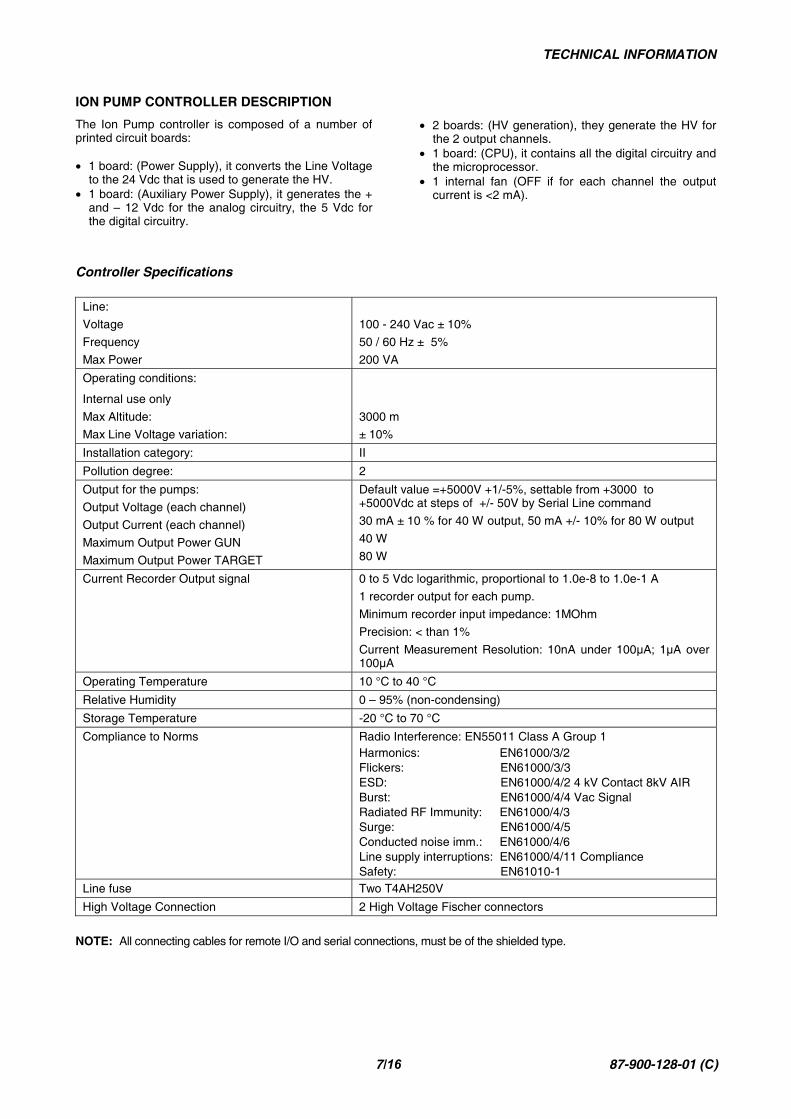
ION PUMP CONTROLLER DESCRIPTION
The Ion Pump controller is composed of a number ofprinted circuit boards:
• 1 board: (Power Supply), it converts the Line Voltageto the 24 Vdc that is used to generate the HV.
• 1 board: (Auxiliary Power Supply), it generates the +and – 12 Vdc for the analog circuitry, the 5 Vdc forthe digital circuitry.
• 2 boards: (HV generation), they generate the HV forthe 2 output channels.
• 1 board: (CPU), it contains all the digital circuitry andthe microprocessor.
• 1 internal fan (OFF if for each channel the outputcurrent is <2 mA).
Controller Specifications
Line:
Voltage
Frequency
Max Power
100 - 240 Vac ± 10%
50 / 60 Hz ± 5%
200 VA
Operating conditions:
Internal use only
Max Altitude:
Max Line Voltage variation:
3000 m
± 10%
Installation category: II
Pollution degree: 2
Output for the pumps:
Output Voltage (each channel)
Output Current (each channel)
Maximum Output Power GUN
Maximum Output Power TARGET
Default value =+5000V +1/-5%, settable from +3000 to+5000Vdc at steps of +/- 50V by Serial Line command
30 mA ± 10 % for 40 W output, 50 mA +/- 10% for 80 W output
40 W
80 W
Current Recorder Output signal 0 to 5 Vdc logarithmic, proportional to 1.0e-8 to 1.0e-1 A
1 recorder output for each pump.
Minimum recorder input impedance: 1MOhm
Precision: < than 1%
Current Measurement Resolution: 10nA under 100µA; 1µA over100µA
Operating Temperature 10 °C to 40 °C
Relative Humidity 0 – 95% (non-condensing)
Storage Temperature -20 °C to 70 °C
Compliance to Norms Radio Interference: EN55011 Class A Group 1Harmonics: EN61000/3/2Flickers: EN61000/3/3ESD: EN61000/4/2 4 kV Contact 8kV AIRBurst: EN61000/4/4 Vac SignalRadiated RF Immunity: EN61000/4/3Surge: EN61000/4/5Conducted noise imm.: EN61000/4/6Line supply interruptions: EN61000/4/11 ComplianceSafety: EN61010-1
Line fuse Two T4AH250V
High Voltage Connection 2 High Voltage Fischer connectors NOTE: All connecting cables for remote I/O and serial connections, must be of the shielded type.
TECHNICAL INFORMATION
8/16 87-900-128-01 (C)
MAINS
TARGET
SERIAL
/LOCAL
/
/
MODE
/
/
BATTERYF1 T4AH250V
FUSE
F2 T4AH250V
INPUTLINE
400.00400.00
201.
60
400.00
146
.80
400.00
420.00
OI
REMOTE I/O
SERIAL
CABLE INTERLOCKTARGET
TARGET
HV OUTPUT
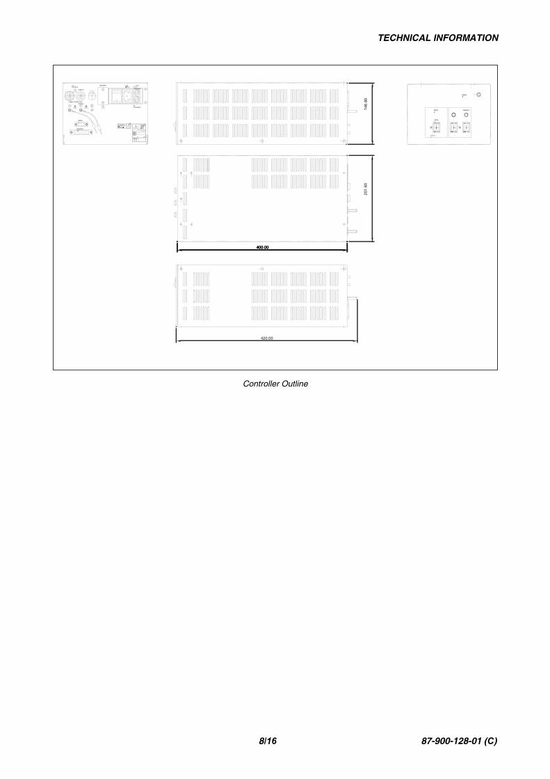
Controller Outline
TECHNICAL INFORMATION
9/16 87-900-128-01 (C)
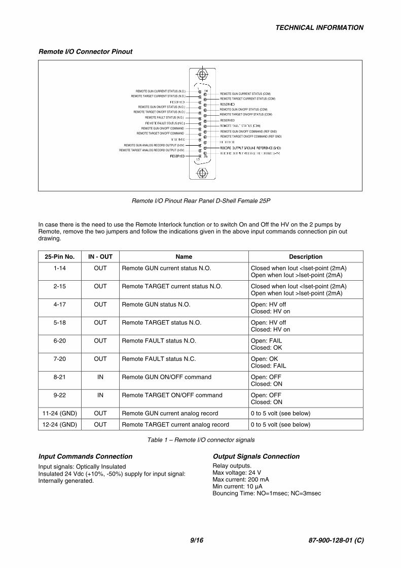
Remote I/O Connector Pinout
REMOTE FAULT STATUS (N.O.)RESERVED
REMOTE GUN CURRENT STATUS (N.O.)
REMOTE TARGET CURRENT STATUS (N.O.)
REMOTE GUN ON/OFF STATUS (N.O.)
REMOTE TARGET ON/OFF STATUS (N.O.)
REMOTE GUN ON/OFF COMMAND
REMOTE TARGET ON/OFF COMMAND
REMOTE GUN ANALOG RECORD OUTPUT (0-5V)
REMOTE TARGET ANALOG RECORD OUTPUT (0-5V)
REMOTE GUN CURRENT STATUS (COM)
REMOTE TARGET CURRENT STATUS (COM)
REMOTE GUN ON/OFF STATUS (COM)
REMOTE TARGET ON/OFF STATUS (COM)
REMOTE GUN ON/OFF COMMAND (REF GND)
REMOTE TARGET ON/OFF COMMAND (REF GND)
Remote I/O Pinout Rear Panel D-Shell Female 25P
In case there is the need to use the Remote Interlock function or to switch On and Off the HV on the 2 pumps byRemote, remove the two jumpers and follow the indications given in the above input commands connection pin outdrawing.
25-Pin No. IN - OUT Name Description
1-14 OUT Remote GUN current status N.O. Closed when Iout <Iset-point (2mA)Open when Iout >Iset-point (2mA)
2-15 OUT Remote TARGET current status N.O. Closed when Iout <Iset-point (2mA)Open when Iout >Iset-point (2mA)
4-17 OUT Remote GUN status N.O. Open: HV offClosed: HV on
5-18 OUT Remote TARGET status N.O. Open: HV offClosed: HV on
6-20 OUT Remote FAULT status N.O. Open: FAILClosed: OK
7-20 OUT Remote FAULT status N.C. Open: OKClosed: FAIL
8-21 IN Remote GUN ON/OFF command Open: OFFClosed: ON
9-22 IN Remote TARGET ON/OFF command Open: OFFClosed: ON
11-24 (GND) OUT Remote GUN current analog record 0 to 5 volt (see below)
12-24 (GND) OUT Remote TARGET current analog record 0 to 5 volt (see below)
Table 1 – Remote I/O connector signals
Input Commands ConnectionInput signals: Optically InsulatedInsulated 24 Vdc (+10%, -50%) supply for input signal:Internally generated.
Output Signals ConnectionRelay outputs.Max voltage: 24 VMax current: 200 mAMin current: 10 µABouncing Time: NO=1msec; NC=3msec
TECHNICAL INFORMATION
10/16 87-900-128-01 (C)
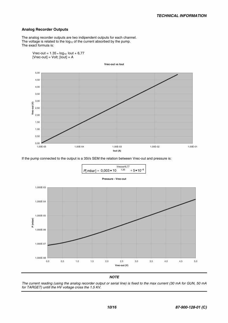
Analog Recorder Outputs
The analog recorder outputs are two indipendent outputs for each channel.The voltage is related to the log10 of the current absorbed by the pump.The exact formula is:
Vrec-out = 1.35 • log10 Iout + 6,77[Vrec-out] = Volt; [Iout] = A
Vrec-out vs Iout
0,00
0,50
1,00
1,50
2,00
2,50
3,00
3,50
4,00
4,50
5,00
1,00E-05 1,00E-04 1,00E-03 1,00E-02 1,00E-01
Iout (A)
Vre
c-o
ut(V
)
If the pump connected to the output is a 35l/s SEM the relation between Vrec-out and pressure is:
Pressure - Vrec-out
1,000E-08
1,000E-07
1,000E-06
1,000E-05
1,000E-04
1,000E-03
0,0 0,5 1,0 1,5 2,0 2,5 3,0 3,5 4,0 4,5 5,0
Vrec-out (V)
P(m
bar
)
NOTE
The current reading (using the analog recorder output or serial line) is fixed to the max current (30 mA for GUN, 50 mAfor TARGET) untill the HV voltage cross the 1.5 KV.
835,177,6
105100,003][ −−
•+•=Vrecout
mbarP
TECHNICAL INFORMATION
11/16 87-900-128-01 (C)
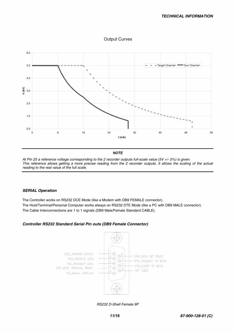
Output Curves
0,0
1,0
2,0
3,0
4,0
5,0
6,0
0 8 16 24 32 40 48 56
I (mA)
V(k
V)
Target Channel Gun Channel
NOTE
At Pin 25 a reference voltage corresponding to the 2 recorder outputs full-scale value (5V +/- 5%) is given.This reference allows getting a more precise reading from the 2 recorder outputs. It allows the scaling of the actualreading to the real value of the full scale.
SERIAL Operation
The Controller works on RS232 DCE Mode (like a Modem with DB9 FEMALE connector).
The Host/Terminal/Personal Computer works always on RS232 DTE Mode (like a PC with DB9 MALE connector).
The Cable Interconnections are 1 to 1 signals (DB9 Male/Female Standard CABLE).
Controller RS232 Standard Serial Pin outs (DB9 Female Connector)
RS232 D-Shell Female 9P
TECHNICAL INFORMATION
12/16 87-900-128-01 (C)
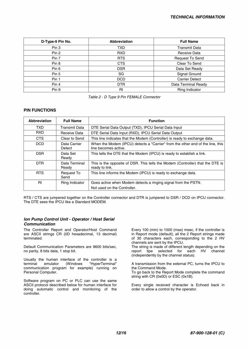
D-Type-9 Pin No. Abbreviation Full Name
Pin 3 TXD Transmit DataPin 2 RXD Receive DataPin 7 RTS Request To SendPin 8 CTS Clear To SendPin 6 DSR Data Set ReadyPin 5 SG Signal GroundPin 1 DCD Carrier DetectPin 4 DTR Data Terminal ReadyPin 9 RI Ring Indicator
Table 2 - D Type 9 Pin FEMALE Connector
PIN FUNCTIONS
Abbreviation Full Name Function
TXD Transmit Data DTE Serial Data Output (TXD), IPCU Serial Data InputRXD Receive Data DTE Serial Data Input (RXD), IPCU Serial Data Output
CTS Clear to Send This line indicates that the Modem (Controller) is ready to exchange data.
DCD Data CarrierDetect
When the Modem (IPCU) detects a "Carrier" from the other end of the line, thisline becomes active.
DSR Data SetReady
This tells the DTE that the Modem (IPCU) is ready to establish a link.
DTR Data TerminalReady
This is the opposite of DSR. This tells the Modem (Controller) that the DTE isready to link.
RTS Request ToSend
This line informs the Modem (IPCU) is ready to exchange data.
RI Ring Indicator Goes active when Modem detects a ringing signal from the PSTN.Not used on the Controller.
RTS / CTS are jumpered together on the Controller connector and DTR is jumpered to DSR / DCD on IPCU connector.The DTE sees the IPCU like a Standard MODEM.
Ion Pump Control Unit - Operator / Host SerialCommunicationThe Controller Report and Operator/Host Commandare ASCII strings CR (0D hexadecimal, 13 decimal)terminated.
Default Communication Parameters are 9600 bits/sec,no parity, 8 bits data, 1 stop bit.
Usually the human interface of the controller is aterminal emulator (Windows "HyperTerminal"communication program for example) running onPersonal Computer.
Software program on PC or PLC can use the sameASCII protocol described below for human interface fordoing automatic control and monitoring of thecontroller.
Every 100 (min) to 1000 (max) msec, if the controller isin Report mode (default), all the 2 Report strings madeof 30 characters each, corresponding to the 2 HVchannels are sent by the IPCU.The string is made of different length depending on thereport tipe selected for each HV channel(independently by the channel status).
A transmission from the external PC, turns the IPCU tothe Command Mode.To go back to the Report Mode complete the commandstring with CR (0x0D) or ESC (0x1B).
Every single received character is Echoed back inorder to allow a control by the operator.
TECHNICAL INFORMATION
13/16 87-900-128-01 (C)
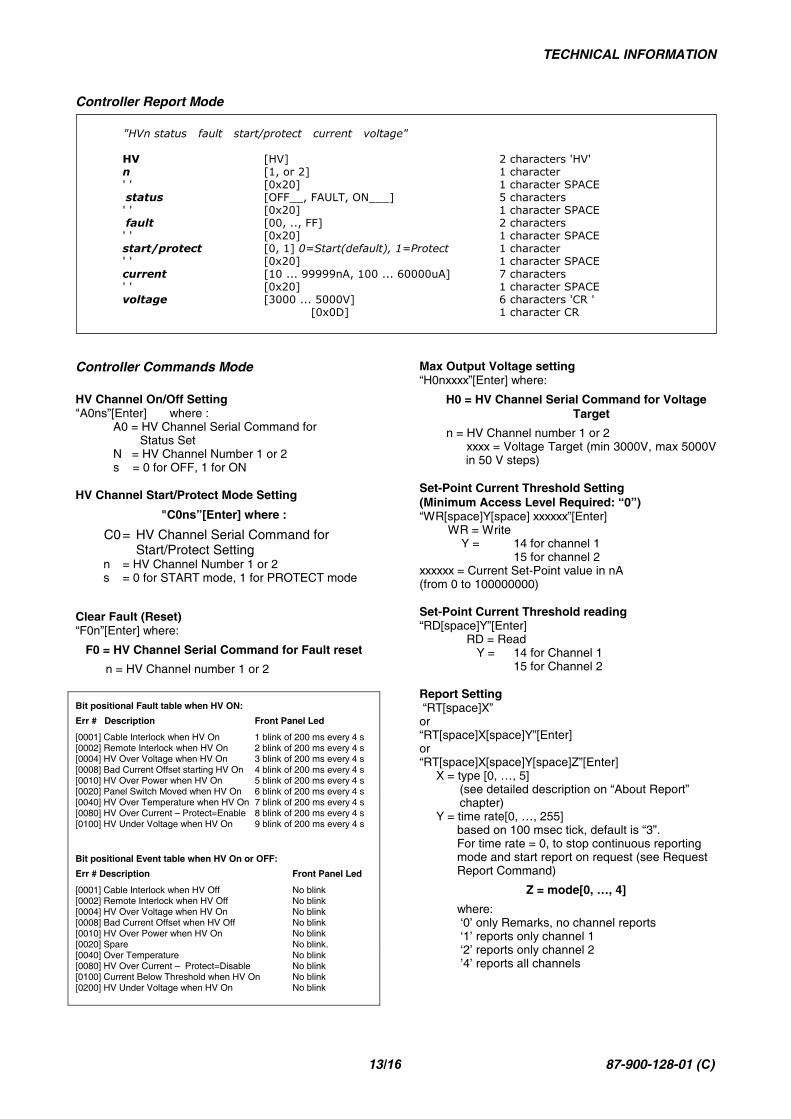
Controller Report Mode
"HVn status fault start/protect current voltage"
HV [HV] 2 characters 'HV'n [1, or 2] 1 character' ' [0x20] 1 character SPACEstatus [OFF__, FAULT, ON___] 5 characters' ' [0x20] 1 character SPACEfault [00, .., FF] 2 characters' ' [0x20] 1 character SPACEstart/protect [0, 1] 0=Start(default), 1=Protect 1 character' ' [0x20] 1 character SPACEcurrent [10 ... 99999nA, 100 ... 60000uA] 7 characters' ' [0x20] 1 character SPACEvoltage [3000 ... 5000V] 6 characters 'CR '
[0x0D] 1 character CR
Controller Commands Mode
HV Channel On/Off Setting"A0ns”[Enter] where :
A0 = HV Channel Serial Command for Status SetN = HV Channel Number 1 or 2s = 0 for OFF, 1 for ON
HV Channel Start/Protect Mode Setting
"C0ns”[Enter] where :
C0= HV Channel Serial Command for Start/Protect Setting
n = HV Channel Number 1 or 2s = 0 for START mode, 1 for PROTECT mode
Clear Fault (Reset)“F0n”[Enter] where:
F0 = HV Channel Serial Command for Fault reset
n = HV Channel number 1 or 2
Bit positional Fault table when HV ON:
Err # Description Front Panel Led
[0001] Cable Interlock when HV On 1 blink of 200 ms every 4 s[0002] Remote Interlock when HV On 2 blink of 200 ms every 4 s[0004] HV Over Voltage when HV On 3 blink of 200 ms every 4 s[0008] Bad Current Offset starting HV On 4 blink of 200 ms every 4 s[0010] HV Over Power when HV On 5 blink of 200 ms every 4 s[0020] Panel Switch Moved when HV On 6 blink of 200 ms every 4 s[0040] HV Over Temperature when HV On 7 blink of 200 ms every 4 s[0080] HV Over Current – Protect=Enable 8 blink of 200 ms every 4 s[0100] HV Under Voltage when HV On 9 blink of 200 ms every 4 s
Bit positional Event table when HV On or OFF:
Err # Description Front Panel Led
[0001] Cable Interlock when HV Off No blink[0002] Remote Interlock when HV Off No blink[0004] HV Over Voltage when HV On No blink[0008] Bad Current Offset when HV Off No blink[0010] HV Over Power when HV On No blink[0020] Spare No blink.[0040] Over Temperature No blink[0080] HV Over Current – Protect=Disable No blink[0100] Current Below Threshold when HV On No blink[0200] HV Under Voltage when HV On No blink
Max Output Voltage setting“H0nxxxx”[Enter] where:
H0 = HV Channel Serial Command for Voltage Target
n = HV Channel number 1 or 2xxxx = Voltage Target (min 3000V, max 5000Vin 50 V steps)
Set-Point Current Threshold Setting(Minimum Access Level Required: “0”)“WR[space]Y[space] xxxxxx”[Enter]
WR = Write Y = 14 for channel 1
15 for channel 2xxxxxx = Current Set-Point value in nA(from 0 to 100000000)
Set-Point Current Threshold reading“RD[space]Y”[Enter]
RD = Read Y = 14 for Channel 1
15 for Channel 2
Report Setting “RT[space]X”or“RT[space]X[space]Y”[Enter]or“RT[space]X[space]Y[space]Z”[Enter] X = type [0, …, 5] (see detailed description on “About Report” chapter) Y = time rate[0, …, 255]
based on 100 msec tick, default is “3”.For time rate = 0, to stop continuous reportingmode and start report on request (see RequestReport Command)
Z = mode[0, …, 4]
where: ‘0’ only Remarks, no channel reports ‘1’ reports only channel 1 ‘2’ reports only channel 2 ’4’ reports all channels
TECHNICAL INFORMATION
14/16 87-900-128-01 (C)
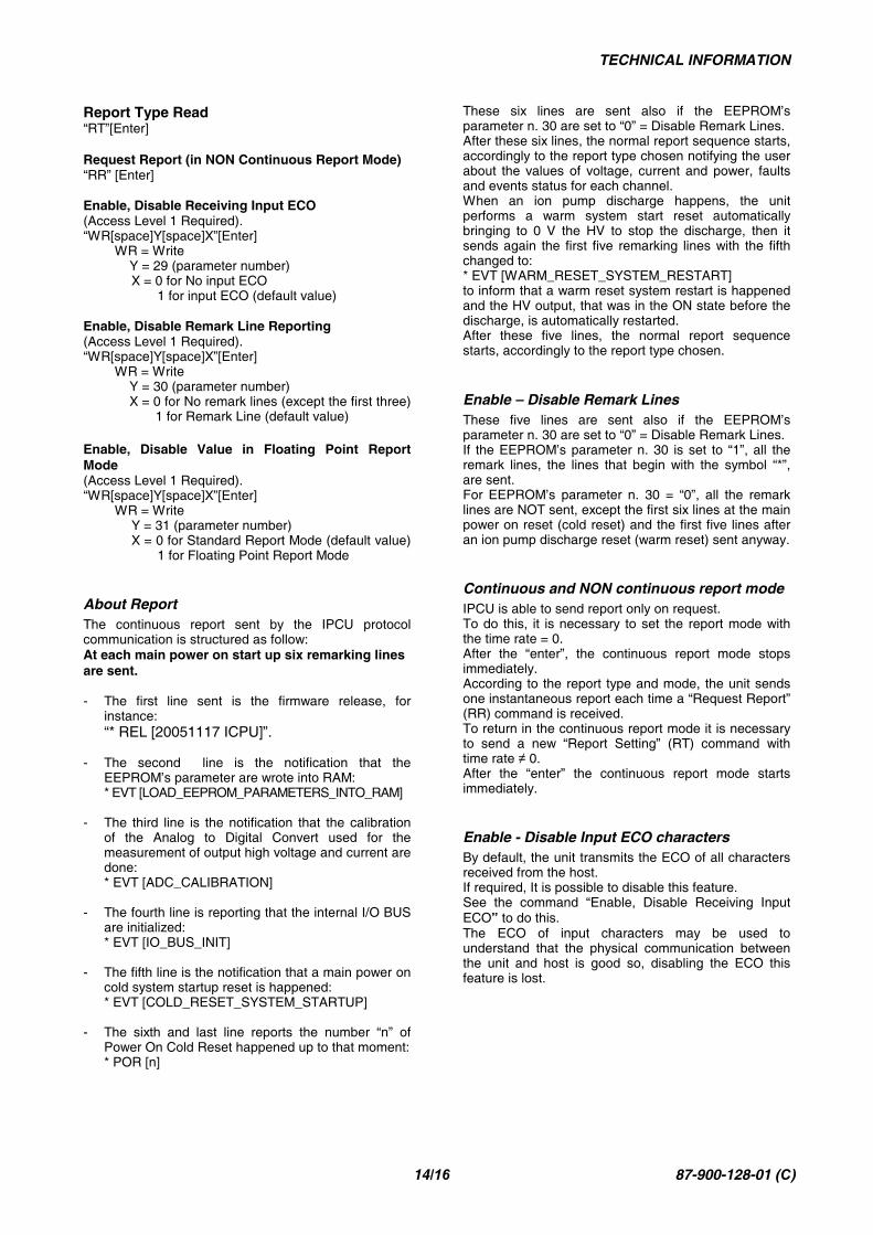
Report Type Read“RT”[Enter]
Request Report (in NON Continuous Report Mode)“RR” [Enter]
Enable, Disable Receiving Input ECO(Access Level 1 Required).“WR[space]Y[space]X”[Enter]
WR = Write Y = 29 (parameter number)
X = 0 for No input ECO 1 for input ECO (default value)
Enable, Disable Remark Line Reporting(Access Level 1 Required).“WR[space]Y[space]X”[Enter]
WR = Write Y = 30 (parameter number) X = 0 for No remark lines (except the first three) 1 for Remark Line (default value)
Enable, Disable Value in Floating Point ReportMode(Access Level 1 Required).“WR[space]Y[space]X”[Enter]
WR = Write Y = 31 (parameter number) X = 0 for Standard Report Mode (default value) 1 for Floating Point Report Mode
About ReportThe continuous report sent by the IPCU protocolcommunication is structured as follow:At each main power on start up six remarking linesare sent.
- The first line sent is the firmware release, forinstance:“* REL [20051117 ICPU]”.
- The second line is the notification that theEEPROM’s parameter are wrote into RAM:* EVT [LOAD_EEPROM_PARAMETERS_INTO_RAM]
- The third line is the notification that the calibrationof the Analog to Digital Convert used for themeasurement of output high voltage and current aredone:* EVT [ADC_CALIBRATION]
- The fourth line is reporting that the internal I/O BUSare initialized:* EVT [IO_BUS_INIT]
- The fifth line is the notification that a main power oncold system startup reset is happened:* EVT [COLD_RESET_SYSTEM_STARTUP]
- The sixth and last line reports the number “n” ofPower On Cold Reset happened up to that moment:* POR [n]
These six lines are sent also if the EEPROM’sparameter n. 30 are set to “0” = Disable Remark Lines.After these six lines, the normal report sequence starts,accordingly to the report type chosen notifying the userabout the values of voltage, current and power, faultsand events status for each channel.When an ion pump discharge happens, the unitperforms a warm system start reset automaticallybringing to 0 V the HV to stop the discharge, then itsends again the first five remarking lines with the fifthchanged to:* EVT [WARM_RESET_SYSTEM_RESTART]to inform that a warm reset system restart is happenedand the HV output, that was in the ON state before thedischarge, is automatically restarted.After these five lines, the normal report sequencestarts, accordingly to the report type chosen.
Enable – Disable Remark LinesThese five lines are sent also if the EEPROM’sparameter n. 30 are set to “0” = Disable Remark Lines.If the EEPROM’s parameter n. 30 is set to “1”, all theremark lines, the lines that begin with the symbol “*”,are sent.For EEPROM’s parameter n. 30 = “0”, all the remarklines are NOT sent, except the first six lines at the mainpower on reset (cold reset) and the first five lines afteran ion pump discharge reset (warm reset) sent anyway.
Continuous and NON continuous report modeIPCU is able to send report only on request.To do this, it is necessary to set the report mode withthe time rate = 0.After the “enter”, the continuous report mode stopsimmediately.According to the report type and mode, the unit sendsone instantaneous report each time a “Request Report”(RR) command is received.To return in the continuous report mode it is necessaryto send a new “Report Setting” (RT) command withtime rate ≠ 0.After the “enter” the continuous report mode startsimmediately.
Enable - Disable Input ECO charactersBy default, the unit transmits the ECO of all charactersreceived from the host.If required, It is possible to disable this feature.See the command “Enable, Disable Receiving InputECO” to do this.The ECO of input characters may be used tounderstand that the physical communication betweenthe unit and host is good so, disabling the ECO thisfeature is lost.
TECHNICAL INFORMATION
15/16 87-900-128-01 (C)
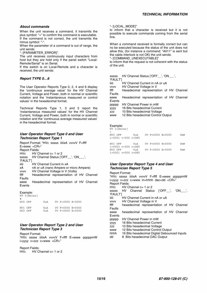
About commandsWhen the unit receives a command, it transmits theplus symbol: “+” to confirm the command is executable.If the command is not correct, the unit transmits theminus symbol: “-“.When the parameter of a command is out of range, theunit sends:“- [PARAMETER_ERROR]”.The unit receives continuously input characters fromhost but they are hold only if the panel switch “Local-Remote/Serial” is on Serial.If this switch is on Local-Remote and a character isreceived, the unit sends:
Report TYPE 0…6
The User Operator Reports Type 0, 2, 4 and 6 displaythe ‘continuous average value’ for the HV ChannelCurrent, Voltage and Power, both in normal or scientificnotation and the ‘instantaneous measured or controlvalues’ in the hexadecimal format.
Technical Reports Type 1, 3 and 5 report the‘instantaneous measured values’ for the HV ChannelCurrent, Voltage and Power, both in normal or scientificnotation and the ‘continuous average measured values’in the hexadecimal format.
User Operator Report Type 0 and UserTechnician Report Type 1Report Format: “HVc sssss iiiiixA vvvvV F=ffffE=eeee <CR>”Report Fields:HVc HV Channel c= 1 or 2sssss HV Channel Status [‘OFF__’, ‘ON___’,‘FAULT’]iiiii HV Channel Current in xAxA nA or uA (nano Ampere or micro Ampere)vvvv HV Channel Voltage in V (Volts)ffff Hexadecimal representation of HV ChannelFaultseeee Hexadecimal representation of HV ChannelEvents
Example:RT 0[Enter]+HV2 OFF 0uA 0V F=0000 E=0000
HV1 OFF 0uA 0V F=0000 E=0000HV2 OFF 0uA 0V F=0000 E=0000
User Operator Report Type 2 and UserTechnician Report Type 3Report Format: “HVc sssss iiiiixA vvvvV F=ffff E=eeee pppppmWi=yyyy v=zzz c=www <CR>”
Report Fields:HVc HV Channel c= 1 or 2
“- [LOCAL_MODE]”to inform that a character is received but it is notpossible to execute commands coming from the serialline.
When a command received is formally correct but canno be executed because the status of the unit does notallow this, (for instance a command: “A011” is sent butthe cable interlock is not OK) the unit sends:“- [COMMAND_UNEXECUTABLE]”to inform that the request is not coherent with the statusof the unit.
sssss HV Channel Status [‘OFF__’, ‘ON___’,‘FAULT’]iiiii HV Channel Current in nA or uAvvvv HV Channel Voltage in Vffff Hexadecimal representation of HV ChannelFaultseeee Hexadecimal representation of HV ChannelEventsppppp HV Channel Power in mWyyyy 16 Bits hexadecimal Currentzzz 10 Bits hexadecimal Voltagewww 12 Bits hexadecimal Control Output
Example:RT 2[Enter]+HV2 OFF 0uA 0V F=0000 E=0000 0mWi=0001 v=000 c=D80
HV1 OFF 0uA 0V F=0000 E=0000 0mWi=0003 v=000 c=D80HV2 OFF 0uA 0V F=0000 E=0000 0mWi=0001 v=000 c=D80
User Operator Report Type 4 and UserTechnician Report Type 5Report Format:“HVc sssss iiiiixA vvvvV F=ffff E=eeee pppppmWi=yyyy v=zzz c=www in=hhhh dac=dd <CR>”Report Fields:HVc HV Channel c= 1 or 2sssss HV Channel Status [‘OFF__’, ‘ON___’,‘FAULT’]iiiii HV Channel Current in nA or uAvvvv HV Channel Voltage in Vffff hexadecimal representation of HV ChannelFaultseeee hexadecimal representation of HV ChannelEventsppppp HV Channel Power in mWyyyy 16 Bits hexadecimal Currentzzz 10 Bits hexadecimal Voltagewww 12 Bits hexadecimal Control Outputhhhh 16 Bits hexadecimal Digital Debounced Inputsdd 8 Bits hexadecimal DAC Output
TECHNICAL INFORMATION
16/16 87-900-128-01 (C)
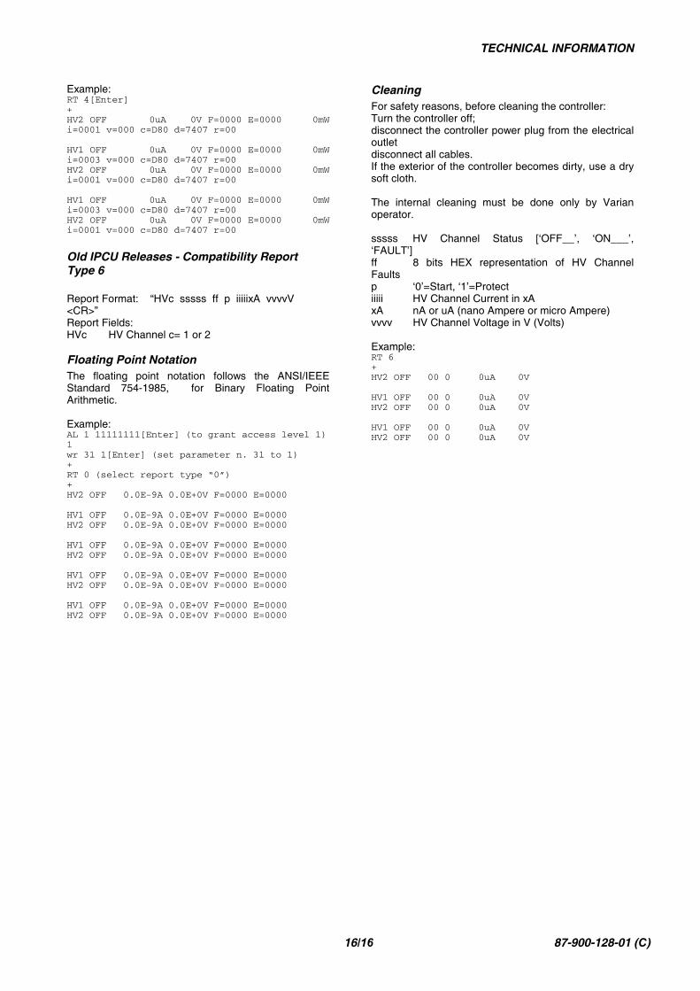
Example:RT 4[Enter]+HV2 OFF 0uA 0V F=0000 E=0000 0mWi=0001 v=000 c=D80 d=7407 r=00
HV1 OFF 0uA 0V F=0000 E=0000 0mWi=0003 v=000 c=D80 d=7407 r=00HV2 OFF 0uA 0V F=0000 E=0000 0mWi=0001 v=000 c=D80 d=7407 r=00
HV1 OFF 0uA 0V F=0000 E=0000 0mWi=0003 v=000 c=D80 d=7407 r=00HV2 OFF 0uA 0V F=0000 E=0000 0mWi=0001 v=000 c=D80 d=7407 r=00
Old IPCU Releases - Compatibility ReportType 6
Report Format: “HVc sssss ff p iiiiixA vvvvV<CR>”Report Fields:HVc HV Channel c= 1 or 2
Floating Point NotationThe floating point notation follows the ANSI/IEEEStandard 754-1985, for Binary Floating PointArithmetic.
Example:AL 1 11111111[Enter] (to grant access level 1)1wr 31 1[Enter] (set parameter n. 31 to 1)+RT 0 (select report type “0”)+HV2 OFF 0.0E-9A 0.0E+0V F=0000 E=0000
HV1 OFF 0.0E-9A 0.0E+0V F=0000 E=0000HV2 OFF 0.0E-9A 0.0E+0V F=0000 E=0000
HV1 OFF 0.0E-9A 0.0E+0V F=0000 E=0000HV2 OFF 0.0E-9A 0.0E+0V F=0000 E=0000
HV1 OFF 0.0E-9A 0.0E+0V F=0000 E=0000HV2 OFF 0.0E-9A 0.0E+0V F=0000 E=0000
HV1 OFF 0.0E-9A 0.0E+0V F=0000 E=0000HV2 OFF 0.0E-9A 0.0E+0V F=0000 E=0000
CleaningFor safety reasons, before cleaning the controller:Turn the controller off;disconnect the controller power plug from the electricaloutletdisconnect all cables.If the exterior of the controller becomes dirty, use a drysoft cloth.
The internal cleaning must be done only by Varianoperator.
sssss HV Channel Status [‘OFF__’, ‘ON___’,‘FAULT’]ff 8 bits HEX representation of HV ChannelFaultsp ‘0’=Start, ‘1’=Protectiiiii HV Channel Current in xAxA nA or uA (nano Ampere or micro Ampere)vvvv HV Channel Voltage in V (Volts)
Example:RT 6+HV2 OFF 00 0 0uA 0V
HV1 OFF 00 0 0uA 0VHV2 OFF 00 0 0uA 0V
HV1 OFF 00 0 0uA 0VHV2 OFF 00 0 0uA 0V
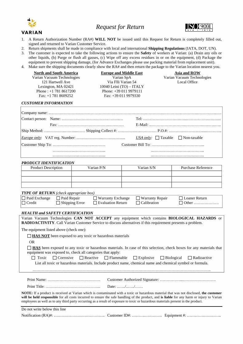
Request for Return
1. A Return Authorization Number (RA#) WILL NOT be issued until this Request for Return is completely filled out, signed and returned to Varian Customer Service.
2. Return shipments shall be made in compliance with local and international Shipping Regulations (IATA, DOT, UN). 3. The customer is expected to take the following actions to ensure the Safety of workers at Varian: (a) Drain any oils or
other liquids, (b) Purge or flush all gasses, (c) Wipe off any excess residues in or on the equipment, (d) Package the equipment to prevent shipping damage, (for Advance Exchanges please use packing material from replacement unit).
4. Make sure the shipping documents clearly show the RA# and then return the package to the Varian location nearest you. North and South America
Varian Vacuum Technologies 121 Hartwell Ave
Lexington, MA 02421 Phone : +1 781 8617200
Fax: +1 781 8609252
Europe and Middle East Varian SpA
Via Flli Varian 54 10040 Leini (TO) – ITALY
Phone: +39 011 9979111 Fax: +39 011 9979330
Asia and ROW Varian Vacuum Technologies
Local Office
CUSTOMER INFORMATION
Company name: ..………………….……..……………….………………………………..……………………...…………..…. Contact person: Name: ……………………………………..… Tel: ……………………….…...…………….….…....
Fax: …………………………….…...…..…… E-Mail: ..……………………..…………..…..…..….. Ship Method: …………….……....…… Shipping Collect #: ………….…..………… P.O.#: ………………….…......………..
Europe only: VAT reg. Number: ………………..……………... USA only: Taxable Non-taxable
Customer Ship To: ………………………….……… Customer Bill To: …………………..……………... ……………..…………………... ..………………………………... ………………..………………... ..………………………………...
PRODUCT IDENTIFICATION Product Description Varian P/N Varian S/N Purchase Reference
TYPE OF RETURN (check appropriate box) Paid Exchange Paid Repair Warranty Exchange Warranty Repair Loaner Return Credit Shipping Error Evaluation Return Calibration Other ……………….
HEALTH and SAFETY CERTIFICATION Varian Vacuum Technologies CAN NOT ACCEPT any equipment which contains BIOLOGICAL HAZARDS or RADIOACTIVITY. Call Varian Customer Service to discuss alternatives if this requirement presents a problem.
The equipment listed above (check one): HAS NOT been exposed to any toxic or hazardous materials OR HAS been exposed to any toxic or hazardous materials. In case of this selection, check boxes for any materials that
equipment was exposed to, check all categories that apply: Toxic Corrosive Reactive Flammable Explosive Biological Radioactive List all toxic or hazardous materials. Include product name, chemical name and chemical symbol or formula.
.……………………………………………………………………………………………………………………..
Print Name: …………………………………. Customer Authorized Signature: ……………...…………………….
Print Title: …………………………………... Date: ..…../..…../…… NOTE: If a product is received at Varian which is contaminated with a toxic or hazardous material that was not disclosed, the customer will be held responsible for all costs incurred to ensure the safe handling of the product, and is liable for any harm or injury to Varian employees as well as to any third party occurring as a result of exposure to toxic or hazardous materials present in the product.
Do not write below this line Notification (RA)#: ……………………….……….. Customer ID#: ……….…………. Equipment #: ……………………..
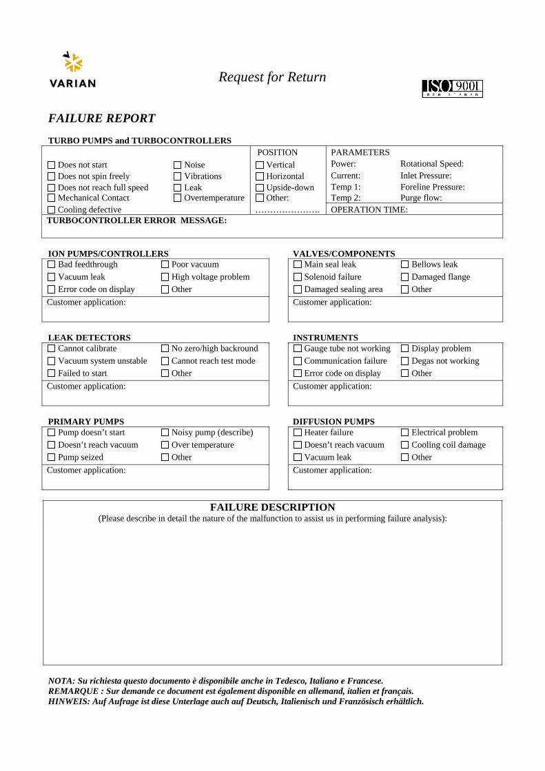
Request for Return
FAILURE REPORT TURBO PUMPS and TURBOCONTROLLERS POSITION PARAMETERS
Does not start Noise Vertical Power: Rotational Speed: Does not spin freely Vibrations Horizontal Current: Inlet Pressure: Does not reach full speed Leak Upside-down Temp 1: Foreline Pressure: Mechanical Contact Overtemperature Other: Temp 2: Purge flow: Cooling defective …………………. OPERATION TIME:
TURBOCONTROLLER ERROR MESSAGE: ION PUMPS/CONTROLLERS VALVES/COMPONENTS
Bad feedthrough Poor vacuum Main seal leak Bellows leak Vacuum leak High voltage problem Solenoid failure Damaged flange Error code on display Other Damaged sealing area Other
Customer application: Customer application: LEAK DETECTORS INSTRUMENTS
Cannot calibrate No zero/high backround Gauge tube not working Display problem Vacuum system unstable Cannot reach test mode Communication failure Degas not working Failed to start Other Error code on display Other
Customer application: Customer application: PRIMARY PUMPS DIFFUSION PUMPS
Pump doesn’t start Noisy pump (describe) Heater failure Electrical problem Doesn’t reach vacuum Over temperature Doesn’t reach vacuum Cooling coil damage Pump seized Other Vacuum leak Other
Customer application: Customer application:
FAILURE DESCRIPTION (Please describe in detail the nature of the malfunction to assist us in performing failure analysis):
NOTA: Su richiesta questo documento è disponibile anche in Tedesco, Italiano e Francese. REMARQUE : Sur demande ce document est également disponible en allemand, italien et français. HINWEIS: Auf Aufrage ist diese Unterlage auch auf Deutsch, Italienisch und Französisch erhältlich.
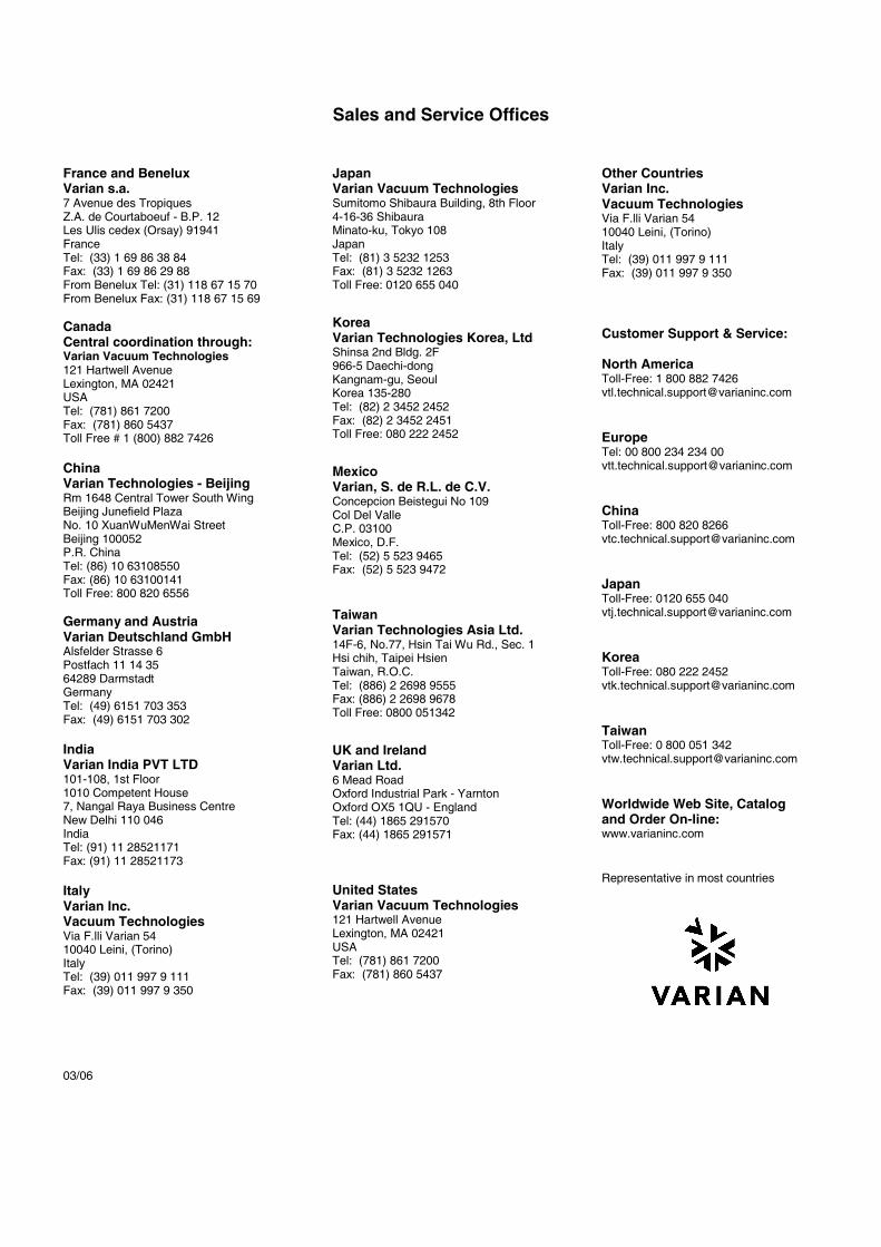
Sales and Service Offices
France and BeneluxVarian s.a.7 Avenue des TropiquesZ.A. de Courtaboeuf - B.P. 12Les Ulis cedex (Orsay) 91941FranceTel: (33) 1 69 86 38 84Fax: (33) 1 69 86 29 88From Benelux Tel: (31) 118 67 15 70From Benelux Fax: (31) 118 67 15 69
CanadaCentral coordination through:Varian Vacuum Technologies121 Hartwell AvenueLexington, MA 02421USATel: (781) 861 7200Fax: (781) 860 5437Toll Free # 1 (800) 882 7426
ChinaVarian Technologies - BeijingRm 1648 Central Tower South WingBeijing Junefield PlazaNo. 10 XuanWuMenWai StreetBeijing 100052P.R. ChinaTel: (86) 10 63108550Fax: (86) 10 63100141Toll Free: 800 820 6556
Germany and AustriaVarian Deutschland GmbHAlsfelder Strasse 6Postfach 11 14 3564289 DarmstadtGermanyTel: (49) 6151 703 353Fax: (49) 6151 703 302
IndiaVarian India PVT LTD101-108, 1st Floor1010 Competent House7, Nangal Raya Business CentreNew Delhi 110 046IndiaTel: (91) 11 28521171Fax: (91) 11 28521173
ItalyVarian Inc.Vacuum TechnologiesVia F.lli Varian 5410040 Leini, (Torino)ItalyTel: (39) 011 997 9 111Fax: (39) 011 997 9 350
03/06
JapanVarian Vacuum TechnologiesSumitomo Shibaura Building, 8th Floor4-16-36 ShibauraMinato-ku, Tokyo 108JapanTel: (81) 3 5232 1253Fax: (81) 3 5232 1263Toll Free: 0120 655 040
KoreaVarian Technologies Korea, LtdShinsa 2nd Bldg. 2F966-5 Daechi-dongKangnam-gu, SeoulKorea 135-280Tel: (82) 2 3452 2452Fax: (82) 2 3452 2451Toll Free: 080 222 2452
MexicoVarian, S. de R.L. de C.V.Concepcion Beistegui No 109Col Del ValleC.P. 03100Mexico, D.F.Tel: (52) 5 523 9465Fax: (52) 5 523 9472
TaiwanVarian Technologies Asia Ltd.14F-6, No.77, Hsin Tai Wu Rd., Sec. 1Hsi chih, Taipei HsienTaiwan, R.O.C.Tel: (886) 2 2698 9555Fax: (886) 2 2698 9678Toll Free: 0800 051342
UK and IrelandVarian Ltd.6 Mead RoadOxford Industrial Park - YarntonOxford OX5 1QU - EnglandTel: (44) 1865 291570Fax: (44) 1865 291571
United StatesVarian Vacuum Technologies121 Hartwell AvenueLexington, MA 02421USATel: (781) 861 7200Fax: (781) 860 5437
Other CountriesVarian Inc.Vacuum TechnologiesVia F.lli Varian 5410040 Leini, (Torino)ItalyTel: (39) 011 997 9 111Fax: (39) 011 997 9 350
Customer Support & Service:
North AmericaToll-Free: 1 800 882 [email protected]
EuropeTel: 00 800 234 234 [email protected]
ChinaToll-Free: 800 820 [email protected]
JapanToll-Free: 0120 655 [email protected]
KoreaToll-Free: 080 222 [email protected]
TaiwanToll-Free: 0 800 051 [email protected]
Worldwide Web Site, Catalogand Order On-line:www.varianinc.com
Representative in most countries