June 10-14, 2002 Ion Pumpsuspas.fnal.gov/materials/02Yale/05_IonPumps.pdf · USPAS June 2002 Ion...
32
USPAS June 2002 Ion Pumps Page 1 The US Particle Accelerator School Ion Pumps The US Particle Accelerator School Ion Pumps Lou Bertolini Lawrence Livermore National Laboratory June 10-14, 2002
Transcript of June 10-14, 2002 Ion Pumpsuspas.fnal.gov/materials/02Yale/05_IonPumps.pdf · USPAS June 2002 Ion...

USPAS June 2002Ion PumpsPage 1
The US Particle Accelerator SchoolIon Pumps
The US Particle Accelerator SchoolIon Pumps
Lou Bertolini
Lawrence Livermore National Laboratory
June 10-14, 2002
USPAS June 2002Ion PumpsPage 2
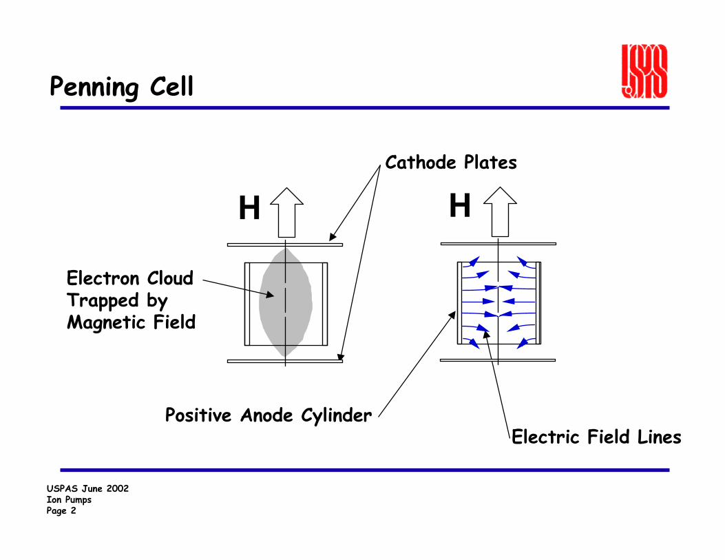
Penning Cell
H H
Electron Cloud Trapped by Magnetic Field
Cathode Plates
Positive Anode CylinderElectric Field Lines
USPAS June 2002Ion PumpsPage 3
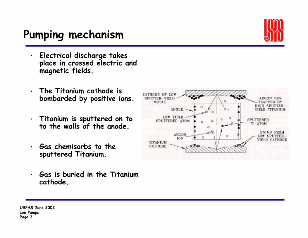
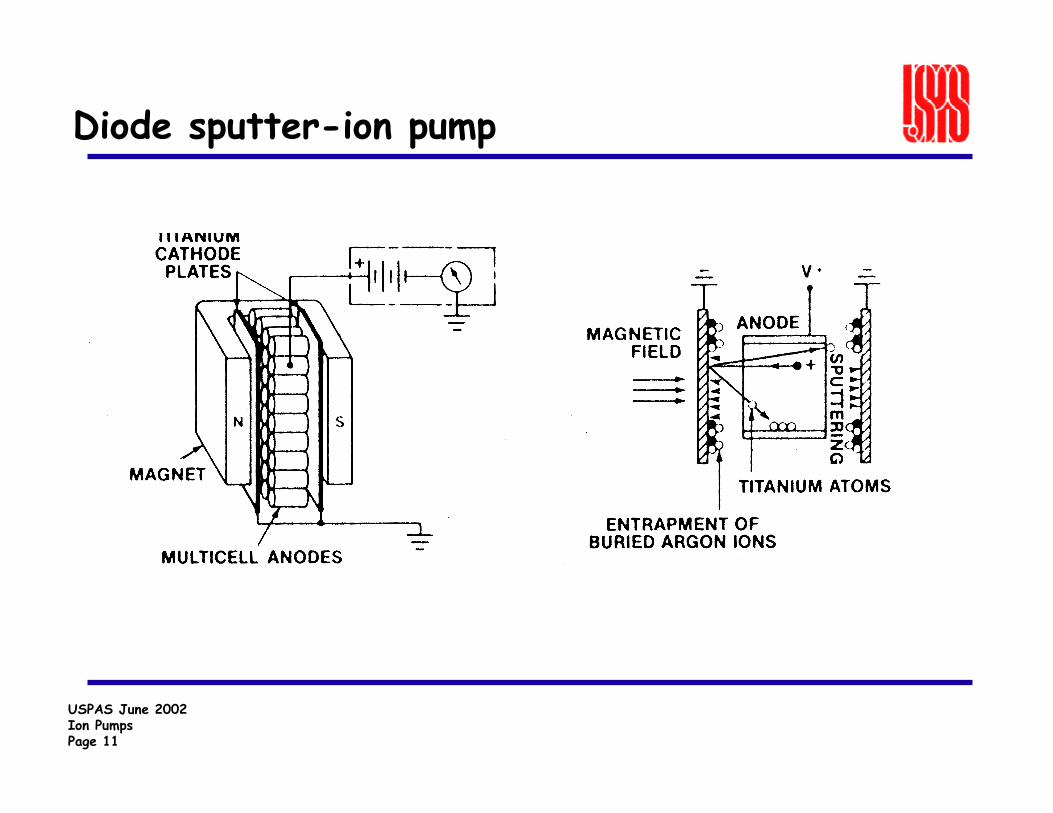
Pumping mechanism
• Electrical discharge takes place in crossed electric and magnetic fields.
• The Titanium cathode is bombarded by positive ions.
• Titanium is sputtered on to to the walls of the anode.
• Gas chemisorbs to the sputtered Titanium.
• Gas is buried in the Titanium cathode.
USPAS June 2002Ion PumpsPage 4
Sputter Ion Pumping Mechanisms
Physisorption - atom burial deep within a lattice, atomburial under sputtered material.
Chemisorption - removal of atoms due to the formation of chemical bonds.
Diffusion - hydrogen diffuses into the bulk of the metal.
USPAS June 2002Ion PumpsPage 5
Sputter-ion pump characteristics• Pumping speed - is sensitive to gas species, inlet size, pressure, and
history of pump• Starting pressure - ion pumps must be roughed to 20 milliTorr or less
before starting (should be more like 10-6 Torr)• Capacity - sputter ion pumps are gas capture type pumps and do have
a limited capacity
• Ultra clean• Quiet Advantages• High pumping speed for water, hydrogen
• Gas species sensitive• Limited capacity Disadvantages

USPAS June 2002Ion PumpsPage 6
Characteristic Parameter of Penning
Penning Cell Sensitivity
Where I+ = ion current (Amps)P = pressure (Torr)
PI = S+
USPAS June 2002Ion PumpsPage 7
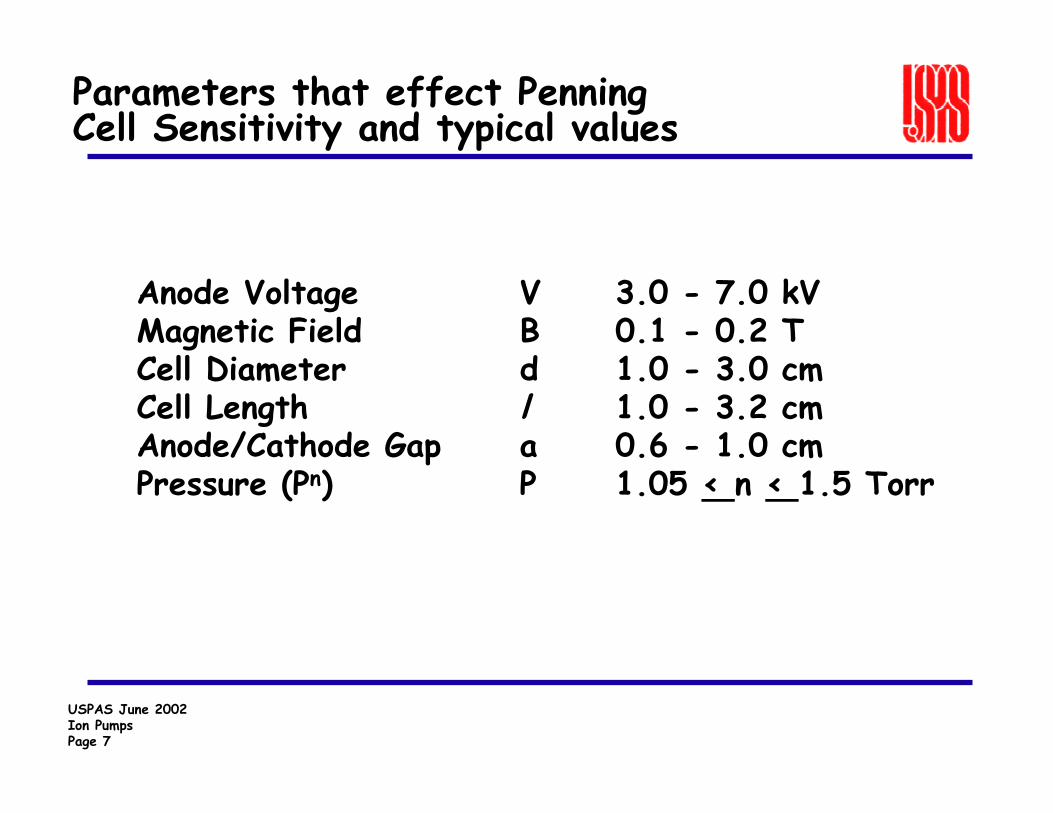
Parameters that effect Penning Cell Sensitivity and typical values
Anode Voltage V 3.0 - 7.0 kVMagnetic Field B 0.1 - 0.2 TCell Diameter d 1.0 - 3.0 cmCell Length l 1.0 - 3.2 cmAnode/Cathode Gap a 0.6 - 1.0 cmPressure (Pn) P 1.05 < n < 1.5 Torr
USPAS June 2002Ion PumpsPage 8
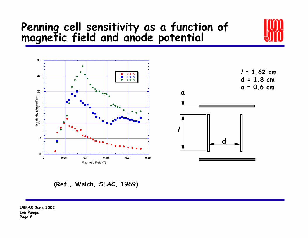
Penning cell sensitivity as a function of magnetic field and anode potential
l = 1.62 cmd = 1.8 cma = 0.6 cm
(Ref., Welch, SLAC, 1969)
0
5
10
15
20
25
30
0 0.05 0.1 0.15 0.2 0.25
2.0 kV4.0 kV6.0 kV
Sens
itivi
ty (A
mps
/Tor
r)
Magnetic Field (T)
l
a
d
USPAS June 2002Ion PumpsPage 9
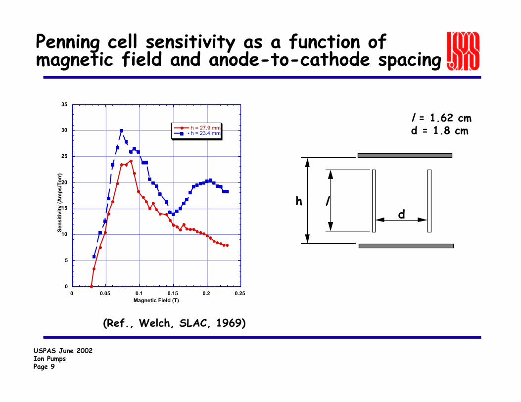
Penning cell sensitivity as a function of magnetic field and anode-to-cathode spacing
l = 1.62 cmd = 1.8 cm
0
5
10
15
20
25
30
35
0 0.05 0.1 0.15 0.2 0.25
h = 27.9 mmh = 23.4 mm
Sens
itivi
ty (A
mps
/Tor
r)
Magnetic Field (T)
(Ref., Welch, SLAC, 1969)
dlh
USPAS June 2002Ion PumpsPage 10
Types of sputter-ion pumps
• Diode - best for UHV systems where 98% of the gas is hydrogen. Diodes have the highest hydrogen pumping speed.
• Differential (Noble Diode) – a compromise for hydrogen pumping speed with limited argon stability. This pump has reduced hydrogen pumping speed.
• Triode/Starcell - good hydrogen pumping speed, also pumps argon well. Good choice for pumping down from higher pressures often.
USPAS June 2002Ion PumpsPage 11
Diode sputter-ion pump
USPAS June 2002Ion PumpsPage 12
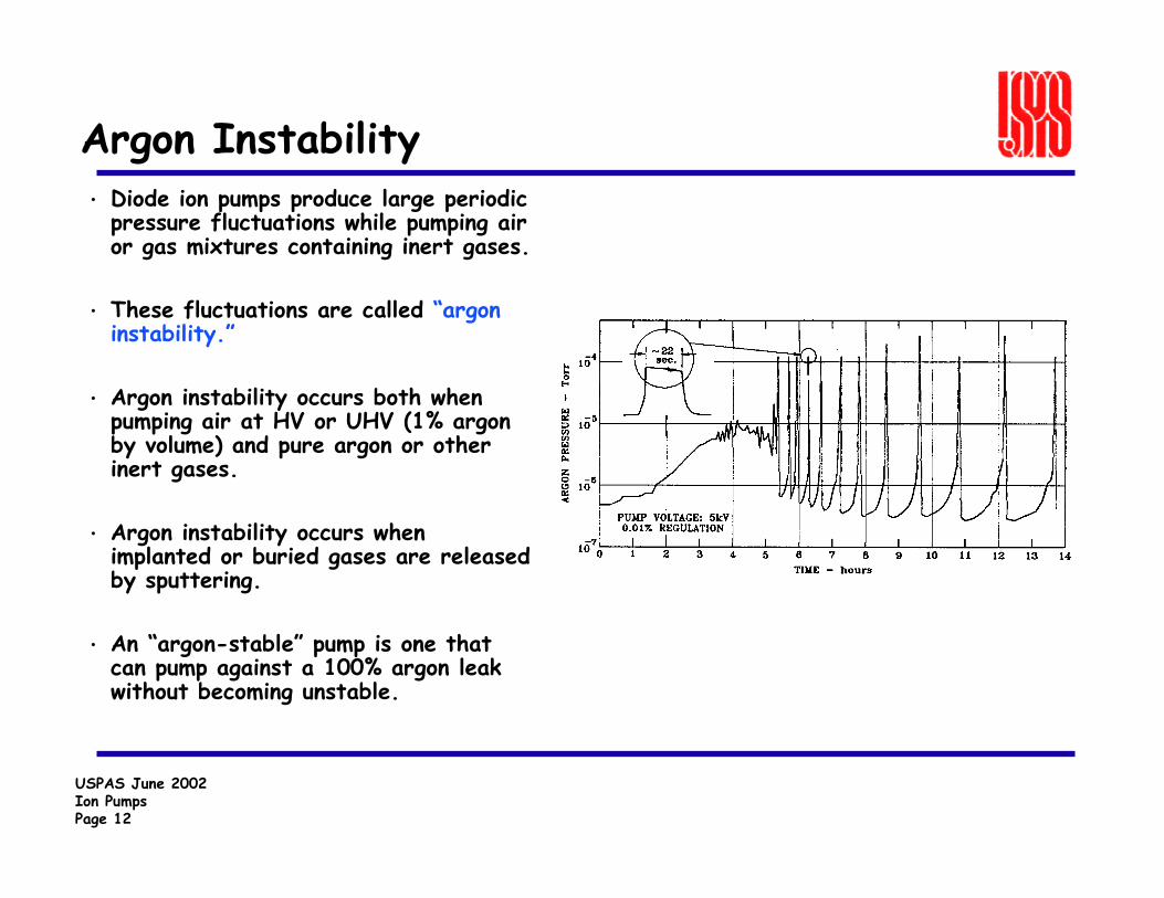
Argon Instability• Diode ion pumps produce large periodic
pressure fluctuations while pumping air or gas mixtures containing inert gases.
• These fluctuations are called “argon instability.”
• Argon instability occurs both when pumping air at HV or UHV (1% argon by volume) and pure argon or other inert gases.
• Argon instability occurs when implanted or buried gases are released by sputtering.
• An “argon-stable” pump is one that can pump against a 100% argon leak without becoming unstable.
USPAS June 2002Ion PumpsPage 13
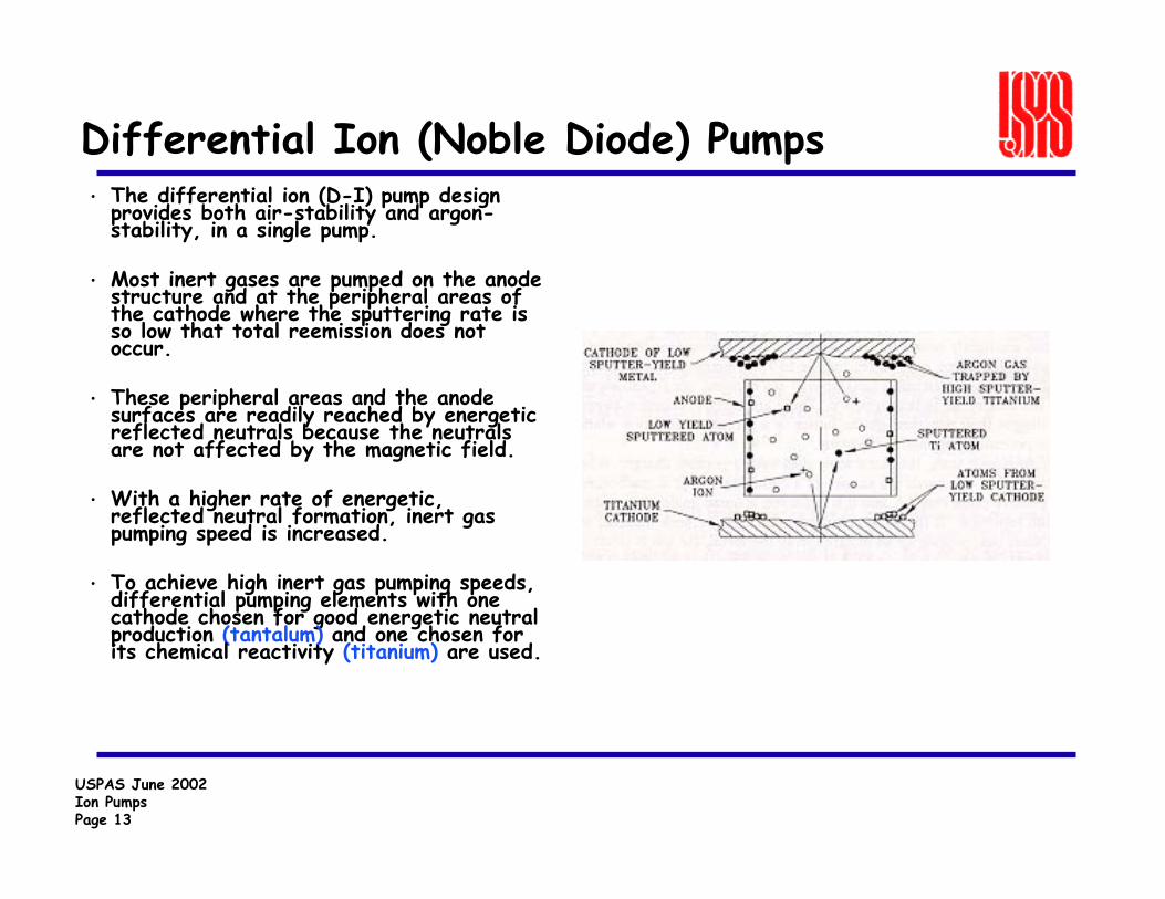
Differential Ion (Noble Diode) Pumps• The differential ion (D-I) pump design
provides both air-stability and argon-stability, in a single pump.
• Most inert gases are pumped on the anode structure and at the peripheral areas of the cathode where the sputtering rate is so low that total reemission does not occur.
• These peripheral areas and the anode surfaces are readily reached by energetic reflected neutrals because the neutrals are not affected by the magnetic field.
• With a higher rate of energetic, reflected neutral formation, inert gas pumping speed is increased.
• To achieve high inert gas pumping speeds, differential pumping elements with one cathode chosen for good energetic neutral production (tantalum) and one chosen for its chemical reactivity (titanium) are used.
USPAS June 2002Ion PumpsPage 14
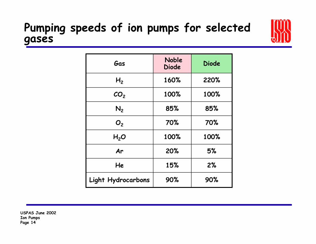
Pumping speeds of ion pumps for selected gases
90%90%Light Hydrocarbons
2%15%He
5%20%Ar
100%100%H2O
70%70%O2
85%85%N2
100%100%CO2
220%160%H2
DiodeNoble DiodeGas
USPAS June 2002Ion PumpsPage 15
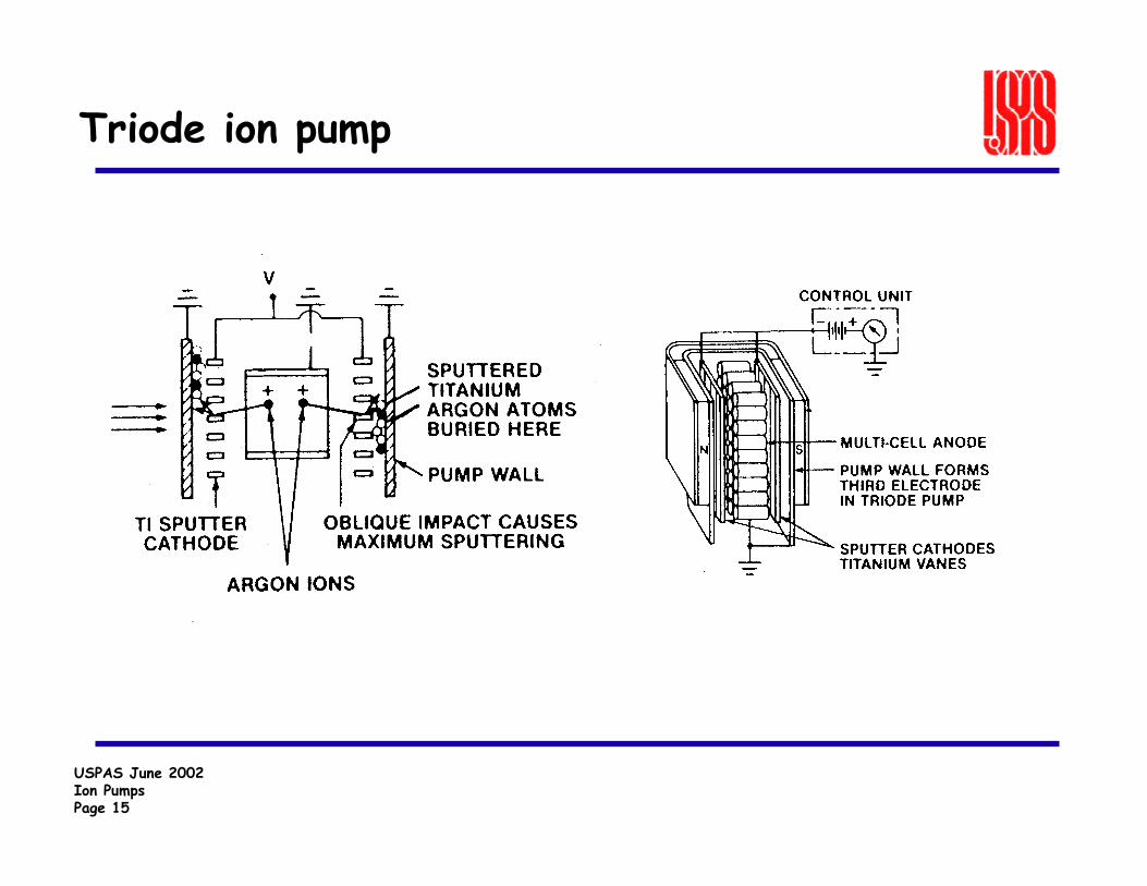
Triode ion pump

USPAS June 2002Ion PumpsPage 16
Starcell Electrodes
• Varian Starcell pump is a variation of the triode design.
USPAS June 2002Ion PumpsPage 17
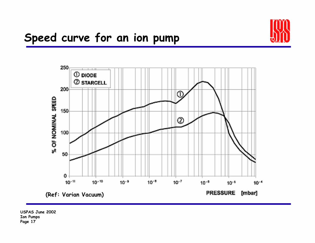
Speed curve for an ion pump
(Ref: Varian Vacuum)

USPAS June 2002Ion PumpsPage 18
Pump speed degrades with time
(Ref: Varian Vacuum)
USPAS June 2002Ion PumpsPage 19
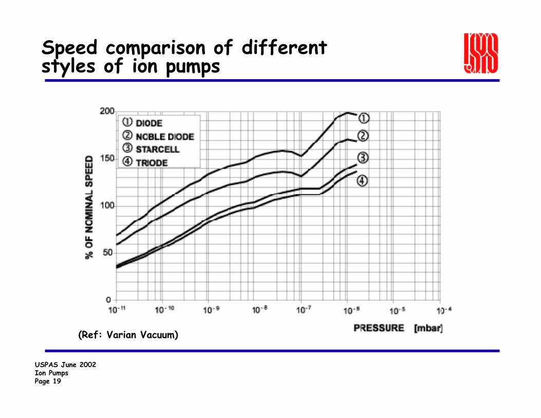
Speed comparison of different styles of ion pumps
(Ref: Varian Vacuum)
USPAS June 2002Ion PumpsPage 20
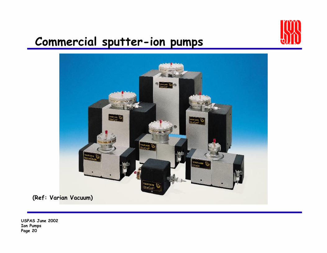
Commercial sputter-ion pumps
(Ref: Varian Vacuum)
USPAS June 2002Ion PumpsPage 21
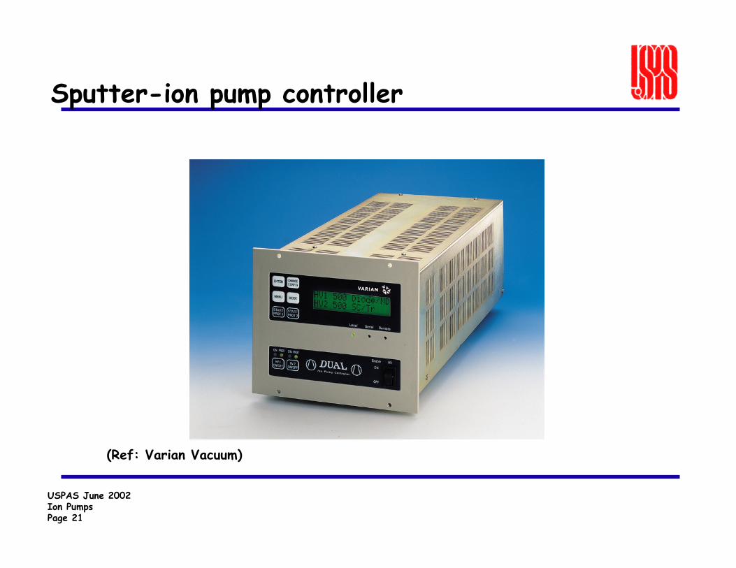
Sputter-ion pump controller
(Ref: Varian Vacuum)
USPAS June 2002Ion PumpsPage 22
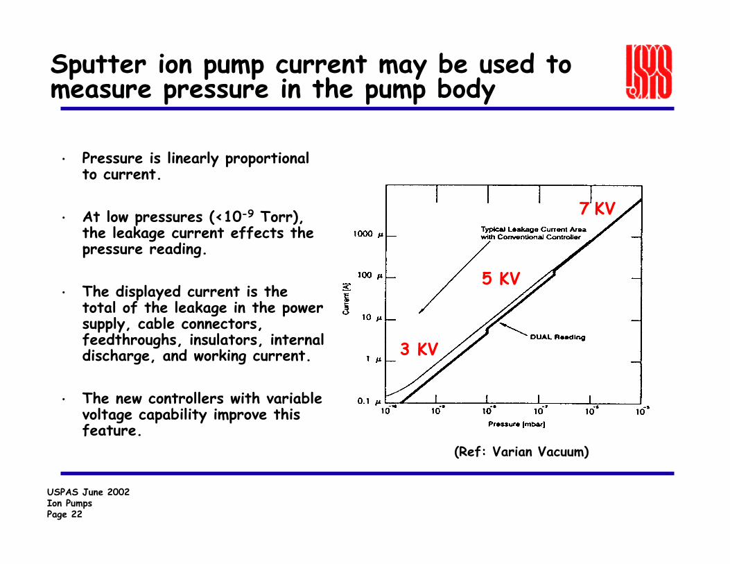
Sputter ion pump current may be used to measure pressure in the pump body
• Pressure is linearly proportional to current.
• At low pressures (<10-9 Torr), the leakage current effects the pressure reading.
• The displayed current is the total of the leakage in the power supply, cable connectors, feedthroughs, insulators, internal discharge, and working current.
• The new controllers with variable voltage capability improve this feature.
7 KV
3 KV
5 KV
(Ref: Varian Vacuum)
USPAS June 2002Ion PumpsPage 23
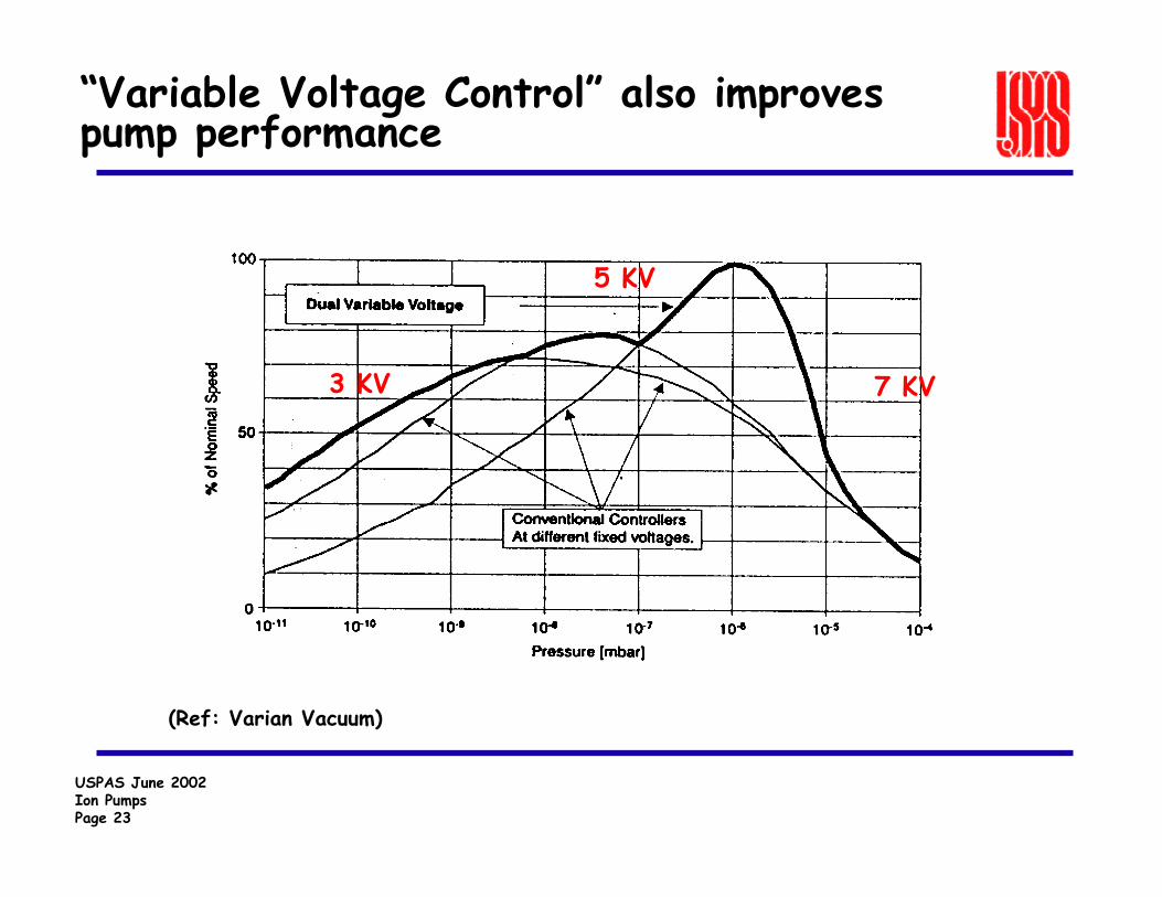
“Variable Voltage Control” also improves pump performance
7 KV
5 KV
3 KV
(Ref: Varian Vacuum)

USPAS June 2002Ion PumpsPage 24
• It is important to match the power supply to the ion pump.— Too large a power supply can
create overheating in the electrodes.
— Too small a power supply will not be able to drive the pump at higher pressures.
• The power supply must provide voltage and current to the ion pump under a variety of conditions.
(Ref: Varian Vacuum)
Electrical characteristics of ion pumps

USPAS June 2002Ion PumpsPage 25
Example – Ion Pumped Vacuum System SNS Linac
Current Design Features:
Accelerator Length
DTL: 36.5 mCCL: 56.5 m
Design Vacuum Level: 10 -7 Torr(with redundancy)
Total Ion Pump Speed: 20,000 L/s
Number of Roughing/Turbo Carts: 15
USPAS June 2002Ion PumpsPage 26
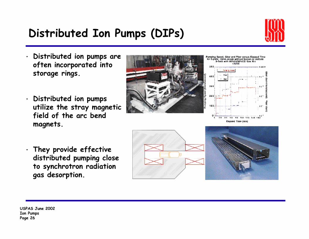
• Distributed ion pumps are often incorporated into storage rings.
• Distributed ion pumps utilize the stray magnetic field of the arc bend magnets.
• They provide effective distributed pumping close to synchrotron radiation gas desorption.
Distributed Ion Pumps (DIPs)
USPAS June 2002Ion PumpsPage 27
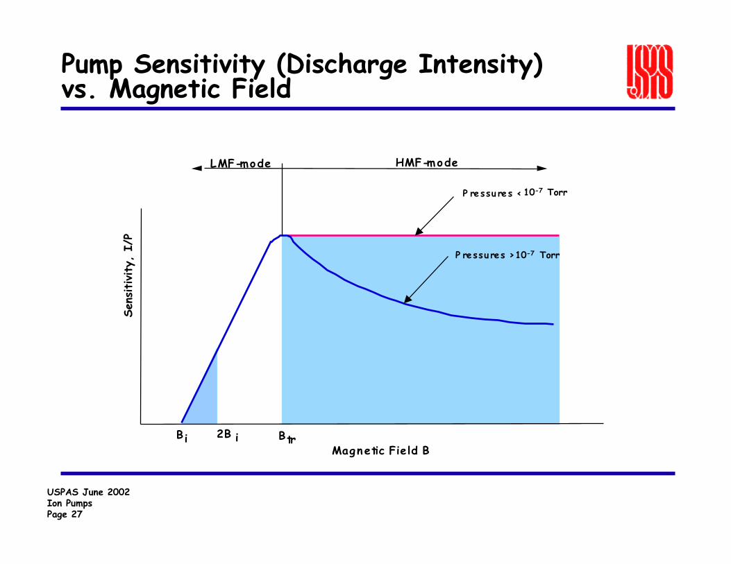
Pump Sensitivity (Discharge Intensity)vs. Magnetic Field
Sens
itivity,
I/P
B i 2B i B trMagnetic Field B
P ressu res >10-7 Torr
P ressu res <
LMF-mode HMF-mode
10-7 Torr
USPAS June 2002Ion PumpsPage 28
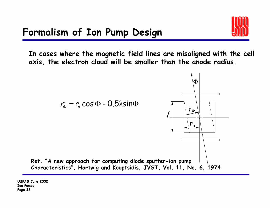
Formalism of Ion Pump Design
In cases where the magnetic field lines are misaligned with the cell axis, the electron cloud will be smaller than the anode radius.
lra
rΦ
Φ
ΦΦ=Φ sin0.5-cosr a λr
Ref. “A new approach for computing diode sputter-ion pumpCharacteristics”, Hartwig and Kouptsidis, JVST, Vol. 11, No. 6, 1974
USPAS June 2002Ion PumpsPage 29
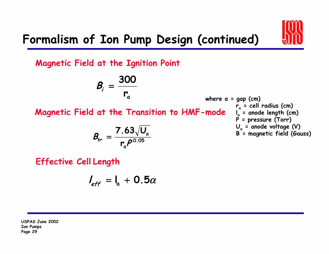
Formalism of Ion Pump Design (continued)
Magnetic Field at the Ignition Point
Effective Cell Length
Magnetic Field at the Transition to HMF-mode
ar300 ====iB
where a = gap (cm)ra = cell radius (cm)la = anode length (cm)P = pressure (Torr)Ua = anode voltage (V)B = magnetic field (Gauss)
05.0a
a
rU7.63
P
Btr ====
αααα0.5l a ++++====effl
USPAS June 2002Ion PumpsPage 30
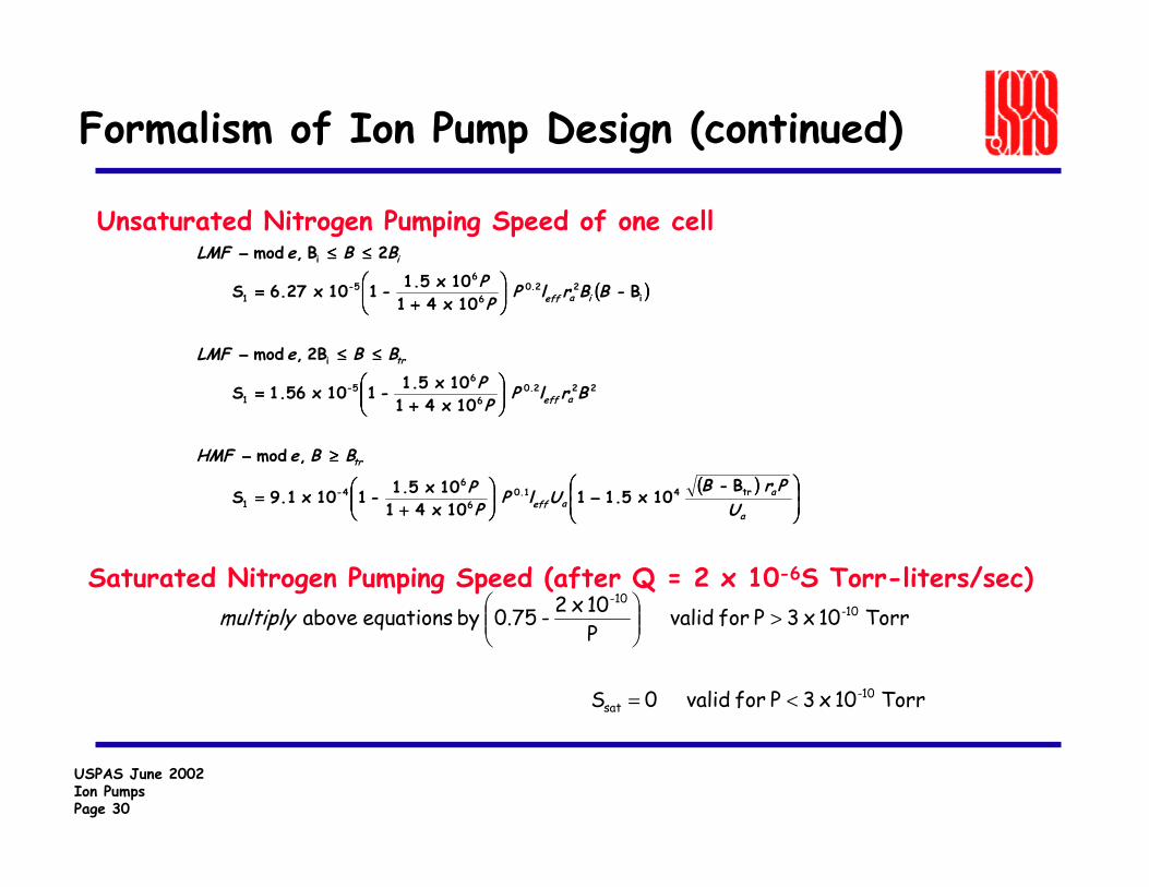
Formalism of Ion Pump Design (continued)
Unsaturated Nitrogen Pumping Speed of one cell
Saturated Nitrogen Pumping Speed (after Q = 2 x 10⁻⁶S Torr-liters/sec)
(((( ))))
(((( ))))
−−−−
++++====
≥≥≥≥−−−−
++++====
≤≤≤≤≤≤≤≤−−−−
++++====
≤≤≤≤≤≤≤≤−−−−
a
aaeff
tr
aeff
tr
iaeff
i
UPrBUlP
PP
BBeHMF
BrlPPP
BBeLMF
BBrlPPP
BBeLMF
B - 10 x1.5 1
10 x 4 110 x1.5 - 110 x9.1 S
,mod
10 x 4 110 x1.5 - 110 x1.56 S
2B ,mod
B - 10 x 4 110 x1.5 - 110 6.27 x S
2B ,mod
tr41.06
64-
1
222.06
65-
1
i
i22.0
6
65-
1
i
Torr 10 x 3P for valid 0 S
Torr 10 x 3P for valid P10 x 2 - 0.75 by equations above
10-sat
10--10
<=
>
multiply
USPAS June 2002Ion PumpsPage 31
Formalism of Ion Pump Design (continued)
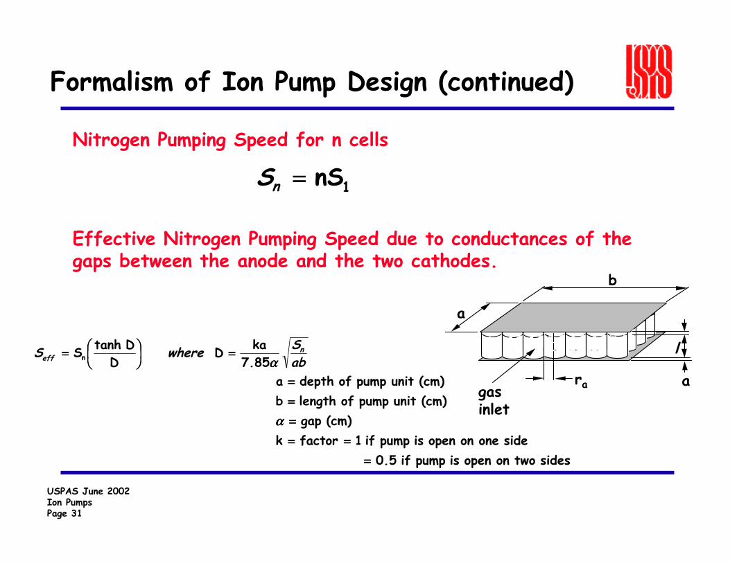
Nitrogen Pumping Speed for n cells
Effective Nitrogen Pumping Speed due to conductances of the gaps between the anode and the two cathodes.
1nS====nS
sides two on open is pump if 0.5 side one on open is pump if 1 factor k
(cm) gap (cm)unit pump of length b (cm)unit pump of depth a
7.85ka D
DD tanhS n
============
============
====
====
αααα
αααα abSwhereS n
eff
a
b
ara
l
gasinlet
USPAS June 2002Ion PumpsPage 32
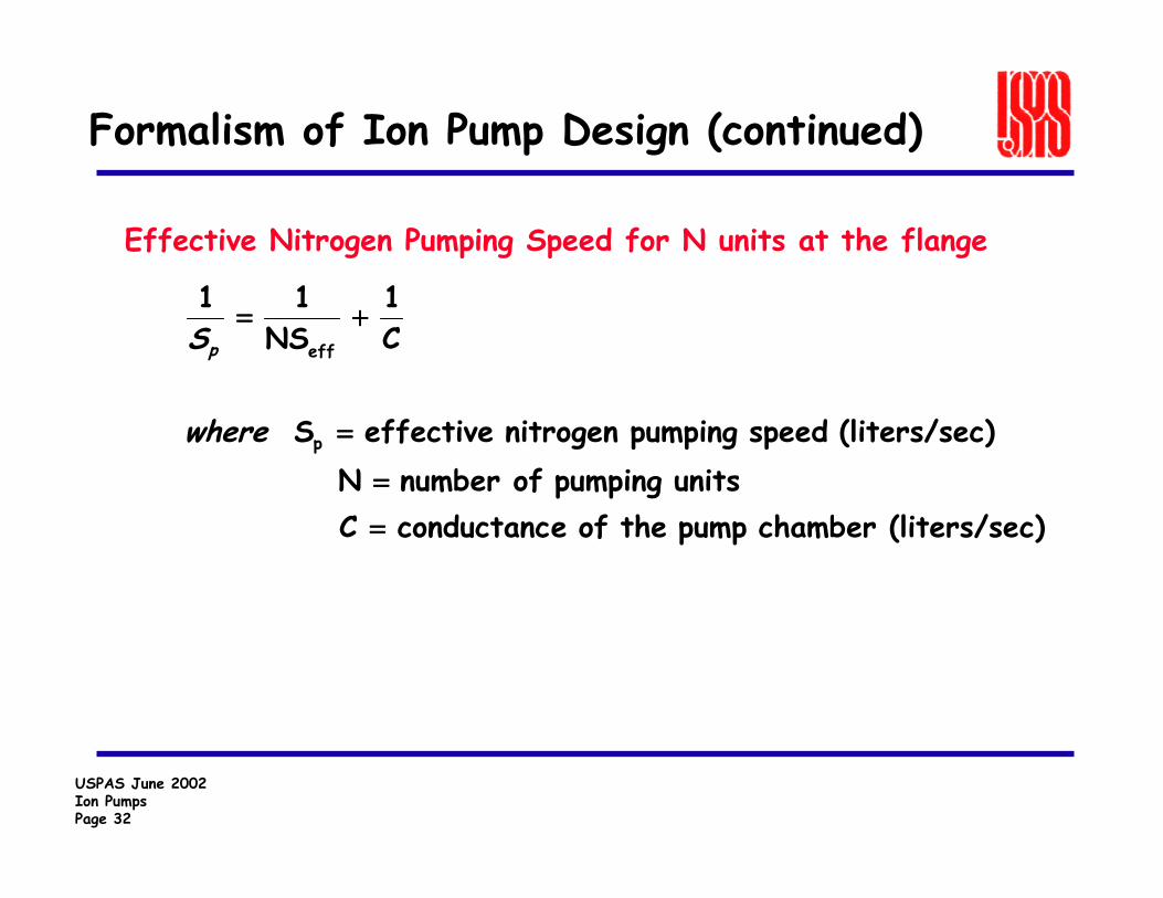
Formalism of Ion Pump Design (continued)
Effective Nitrogen Pumping Speed for N units at the flange
c)(liters/sechamber pump the of econductanc C units pumping ofnumber N
c)(liters/se speed pumping nitrogen effective S
C1
NS1 1
p
eff
========
====
++++====
where
Sp