ESS Vacuum Handbook Part 2 - Vacuum Equipment Standardization · 5.1.4 Sputter Ion Pumps 5.1.4.1...
26
Description Document No 0. Date 23 May 2014 European Spallation Source ESS ERIC www.esss.se ESS Vacuum Handbook Part 2 - Vacuum Equipment Standardization Name Date Author ___________________________________________ Laurence Page Vacuum System Group, STS Reviewer ___________________________________________ Fabio Ravelli Vacuum System Group, STS Approver ___________________________________________ Marcelo Juni Ferreira Vacuum Systems Section Leader, STS
Transcript of ESS Vacuum Handbook Part 2 - Vacuum Equipment Standardization · 5.1.4 Sputter Ion Pumps 5.1.4.1...

Description
Document No 0.
Date 23 May 2014
European Spallation Source ESS ERIC
www.esss.se
ESS Vacuum Handbook
Part 2 - Vacuum Equipment Standardization
Name Date
Author ___________________________________________ Laurence Page Vacuum System Group, STS
Reviewer ___________________________________________ Fabio Ravelli Vacuum System Group, STS
Approver ___________________________________________ Marcelo Juni Ferreira Vacuum Systems Section Leader, STS
Description ESS Vacuum Handbook Part 2
Document No 0.1
Date 11 January 2019
2(26)
Document Revision History
Version Reason for revision Date
0. New Document 2014-05-23
0.1 Update of procurement policy 2019-01-11
Description ESS Vacuum Handbook Part 2
Document No 0.1
Date 11 January 2019
3(26)
Table of Contents
1. Introduction ........................................................................................... 7
2. Scope ...................................................................................................... 7
3. Procurement Policy ................................................................................ 7
4. Pressure Safety Statement ..................................................................... 7
5. Standard Vacuum Equipment ................................................................. 8 5.1 Pumps ............................................................................................... 8
5.1.1 Roughing Pumps ................................................................................. 8 5.1.1.1 Dry Pumps ................................................................................... 8 5.1.1.2 Other Roughing Pumps ................................................................. 8 5.1.1.3 General Requirements for Roughing Pump Installations ................... 9
5.1.2 Cryochillers ......................................................................................... 9 5.1.3 Turbo-molecular and Compound Drag Pumps ........................................ 9 5.1.4 Sputter Ion Pumps ............................................................................. 10
5.1.4.1 Ion Pumps .................................................................................. 10 5.1.4.2 Ion Pump Controllers .................................................................. 10
5.1.5 Non-Evaporable Getter Pumps ............................................................ 10 5.1.6 Combination NEG and Ion Pumps ....................................................... 11 5.1.7 Cryopumps ........................................................................................ 11
5.2 Valves ............................................................................................. 11 5.2.1 Gate Valves ....................................................................................... 12 5.2.2 Angle Valves ..................................................................................... 13 5.2.3 Fast Valves ........................................................................................ 13 5.2.4 Soft-start Valves ................................................................................ 13
5.3 Pressure Relieve Devices ............................................................... 14 5.4 Vent Filters ..................................................................................... 14 5.5 Mass Flow Control System ............................................................. 14 5.6 Vacuum Gauges and Gauge Controllers......................................... 15
5.6.1 General Requirements ........................................................................ 15 5.6.1.1 Gauge Construction and Materials ................................................ 16 5.6.1.2 Gauge Bakeout Temperature ....................................................... 16 5.6.1.3 Gauge Leak Rate ........................................................................ 16
5.6.2 Thermal Conductivity (Pirani) Gauges ................................................. 16 5.6.3 Cold Cathode Gauges (Penning and Inverted Magnetron) .................... 16 5.6.4 Thermal Conductivity and Cold Cathode Gauge Controllers ................... 16
5.6.4.1 Controller Configuration .............................................................. 16 5.6.5 Capacitance Manometers ................................................................... 18
5.7 Leak Detectors ............................................................................... 18 5.7.1 General Requirements ........................................................................ 18 5.7.2 Performance ...................................................................................... 19 5.7.3 Maintainability ................................................................................... 19 5.7.4 Technical Requirements Specification .................................................. 19
5.8 Residual Gas Analysers .................................................................. 20
Description ESS Vacuum Handbook Part 2
Document No 0.1
Date 11 January 2019
4(26)
5.8.1 General Requirements ........................................................................ 20 5.8.2 Performance ...................................................................................... 20
5.8.2.1 Mass Range ................................................................................ 20 5.8.2.2 Minimum Detectable Partial Pressure ............................................ 20 5.8.2.3 Resolution .................................................................................. 20 5.8.2.4 Stability ...................................................................................... 20 5.8.2.5 Ion Source Materials and Construction ......................................... 20 5.8.2.6 Analyzer (Gauge) Head Construction ............................................ 20 5.8.2.7 Analyzer Head Orientation ........................................................... 20
5.9 Mobile Pumping Carts .................................................................... 21
6. Standard Vacuum Equipment ............................................................... 21 6.1 Flange Sealing Systems ................................................................. 21
6.1.1 Flange Types ..................................................................................... 21 6.1.1.1 ISO clamped-type Flanges ........................................................... 21 6.1.1.2 ISO bakable knife-edge flanges (Conflat style - CF) ....................... 22 6.1.1.3 ISO-K and ISO-F flanges (63mm up to typically 630mm) ............... 22 6.1.1.4 Other Flanges ............................................................................. 22
6.1.2 Sealing .............................................................................................. 22 6.1.2.1 Metal Seals ................................................................................. 22 6.1.2.2 Elastomer Seals .......................................................................... 23
6.1.3 Fasteners .......................................................................................... 23 6.2 Bellows ........................................................................................... 23
6.2.1 Hydroformed ..................................................................................... 23 6.2.2 Edge-welded ..................................................................................... 23 6.2.3 Electroformed .................................................................................... 24
7. Applicable Documents .......................................................................... 24
8. Appendix ............................................................................................... 24 8.1 Standards ....................................................................................... 24 Literature ................................................................................................. 25 8.2 Units ............................................................................................... 26
Description ESS Vacuum Handbook Part 2
Document No 0.1
Date 11 January 2019
5(26)
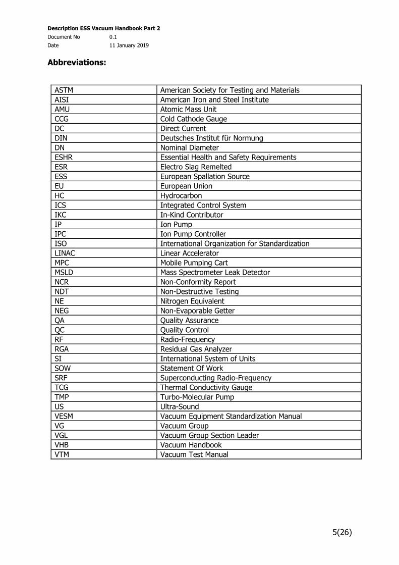
Abbreviations:
ASTM American Society for Testing and Materials
AISI American Iron and Steel Institute
AMU Atomic Mass Unit
CCG Cold Cathode Gauge
DC Direct Current
DIN Deutsches Institut für Normung
DN Nominal Diameter
ESHR Essential Health and Safety Requirements
ESR Electro Slag Remelted
ESS European Spallation Source
EU European Union
HC Hydrocarbon
ICS Integrated Control System
IKC In-Kind Contributor
IP Ion Pump
IPC Ion Pump Controller
ISO International Organization for Standardization
LINAC Linear Accelerator
MPC Mobile Pumping Cart
MSLD Mass Spectrometer Leak Detector
NCR Non-Conformity Report
NDT Non-Destructive Testing
NE Nitrogen Equivalent
NEG Non-Evaporable Getter
QA Quality Assurance
QC Quality Control
RF Radio-Frequency
RGA Residual Gas Analyzer
SI International System of Units
SOW Statement Of Work
SRF Superconducting Radio-Frequency
TCG Thermal Conductivity Gauge
TMP Turbo-Molecular Pump
US Ultra-Sound
VESM Vacuum Equipment Standardization Manual
VG Vacuum Group
VGL Vacuum Group Section Leader
VHB Vacuum Handbook
VTM Vacuum Test Manual
Description ESS Vacuum Handbook Part 2
Document No 0.1
Date 11 January 2019
6(26)
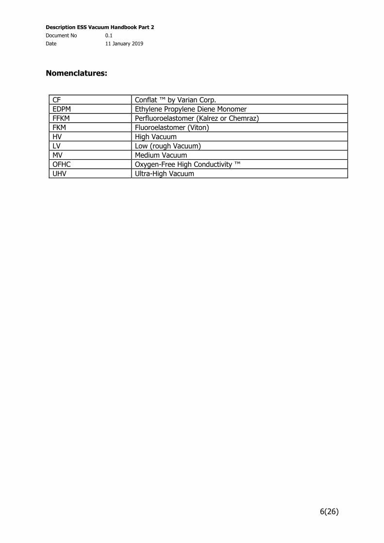
Nomenclatures:
CF Conflat ™ by Varian Corp.
EDPM Ethylene Propylene Diene Monomer
FFKM Perfluoroelastomer (Kalrez or Chemraz)
FKM Fluoroelastomer (Viton)
HV High Vacuum
LV Low (rough Vacuum)
MV Medium Vacuum
OFHC Oxygen-Free High Conductivity ™
UHV Ultra-High Vacuum
Description ESS Vacuum Handbook Part 2
Document No 0.1
Date 11 January 2019
7(26)
1. Introduction
The European Spallation Source (ESS) is an accelerator-driven neutron spallation source. The linear accelerator (LINAC) of which is a critical component. The role of the accelerator is to create protons at the ion source, accelerates them to an appropriate energy, and steer them onto the target to create neutrons via the spallation process for use by a suite of research instruments.
2. Scope
The ESS Vacuum Handbook comprises four (4) parts:
ESS Vacuum Handbook Part 1 – General Requirements for the ESS Technical Vacuum Systems,
ESS Vacuum Handbook Part 2 – Vacuum Equipment Standardization Manual,
ESS Vacuum Handbook Part 3 – Vacuum Design & Fabrication Manual,
ESS Vacuum Handbook Part 4 – Vacuum Test Manual
Part 2 of this Handbook provides requirements and guidelines, for vacuum equipment for use on the accelerator, target neutron instruments, choppers, neutron guides and other supporting equipment e.g. mobile pump carts. It is only applicable to technical vacuum systems and equipment. The implementation of the Vacuum Equipment Standardization policy is to ensure that consistent standards are employed throughout all these systems.
The Vacuum Handbook will be updated periodically throughout the life of the project.
All queries or the request for additional information concerning the contents of this Handbook should be addressed to the ESS Vacuum Group Section Leader (VGL).
3. Procurement Policy
Please refer to tender documents for information regarding procurement.
4. Pressure Safety Statement
Vacuum equipment is designed and rated for a 1 bar differential service pressure unless specifically designed for a higher-pressure value.
If the vacuum device or equipment has the potential to be pressurised to a pressure exceeding 1 bar differential service pressure then relieve devices of sufficient flow capacity must be installed to protect the equipment. Refer to the ESS Vacuum Handbook Part 1, Pressure Rating of Vacuum Vessels and Components, for further information.
For designs that must exceed a 1 bar differential service pressure contact the VG to develop a strategy and equipment specifications where higher differential service pressure can be achieved.
Description ESS Vacuum Handbook Part 2
Document No 0.1
Date 11 January 2019
8(26)
5. Standard Vacuum Equipment
5.1 Pumps
5.1.1 Roughing Pumps
5.1.1.1 Dry Pumps
Dry roughing pumps will be used on the accelerator, target, and neutron instruments including choppers, neutron guides and supporting equipment, e.g. mobile pump carts.
ONLY dry pumps shall be used on the accelerator including associated supporting equipment and mobile pump carts.
Due to cleanliness requirements of the superconducting section of the accelerator ONLY specific pumps will be used. These pumps will be suitably marked for this application.
These pumps shall be dry and free of oils, lubricants, hydrocarbons or other fluids in the pumping chamber and shall not generate particulate or particles during operation.
These pumps shall comply with the “Vacuum Equipment Specification for ESS Dry Roughing Pumps”
1.1.1.1 Oil Sealed Pumps
Where capacity limitations prevent the use of dry pumps, conforming to the above specification, e.g. for the pumping of larger vessels used for neutron instrument applications, oil sealed pumps, including pump sets incorporating blowers (mechanical booster pumps) may be considered. In this case these pumps are to be suitably trapped to avoid the potential for the contamination of equipment due to the back streaming of oil. In general, the pump/ pump set shall be isolated from the chamber/ equipment by an automatic valve that closes on pump shut down while the housing of the pump shall be vented to prevent the possibility of oil being shucked into the equipment.
Oil sealed pumps and pump sets shall be procured against specific equipment specifications developed by the VG to meet specific pumping requirements.
5.1.1.2 Other Roughing Pumps
The selection and use of other types of roughing pump, e.g. liquid ring pumps, pumps with special requirements, e.g. chemical series pumps, explosion proof pumps, oil sealed pumps charged with perfluoro-polyether oils etc. are not precluded, but the application and their selection will be subject to approval of the VG.
In all case the requirements for these pumps will be established by the VG in conjunction with the end user of the equipment to allow a technical specification for this equipment to be developed by the VG.
Description ESS Vacuum Handbook Part 2
Document No 0.1
Date 11 January 2019
9(26)
5.1.1.3 General Requirements for Roughing Pump Installations
Any specific requirement affecting the procurement of a pumping unit shall be identified during the development of the technical specification. If these are additional requirements for which a standard specification exists then this shall form an Appendix to the standard specification. Additional requirements may include but not limited to:
Specific vacuum connections, Electrical supplies, Radiation levels, etc.
5.1.2 Cryochillers
The use of cryochillers, having a closed loop cryogenic refrigeration system, should be considered for the efficient pumping of water vapor, which can constitute up to 65% to 95% of the residual gas load leading to extended pump down times for systems vented directly to air. This is especially true for larger vessels that will be used for neutron instrument applications where the surface area is large.
The cryochiller together with their associated closed loop cryogenic refrigeration system shall be procured against specific equipment technical specifications developed for the procurement by the VG.
5.1.3 Turbo-molecular and Compound Drag Pumps
Turbo-Molecular Pump (TMP) and compound drag pumps will have potential applications in the accelerator, target, neutron instrument including choppers, neutron guides, supporting equipment and mobile pump carts.
TMP’s are suitable for generating a clean vacuum in the pressure range of 10-3 to 10-10 mbar due to their high compression ratio. They will also find application on large instrument tanks that may be cryogenically pumped to provide a leak test capability.
It is desirable that these pumps are suitable for mounting in any orientation, have a high compression ratio for light gasses, have flanges compatible with the equipment on which they are mounted and able to run using detached drive controller’s (remote) with a long radiation resistant cable if needed.
Where possible the pump should be mounted directly to the volume to be evacuated, to maximize conductance, together with an isolation valve to allow in-situ maintenance. The control logic implemented for pump control shall reflect the valve option used.
The drive electronics shall include suitable communication links to interface with the ESS Integrated Control System (ICS) and shall be specified in the equipment specification.
These pumps shall comply with the “Vacuum Equipment Specification for ESS Turbo-molecular”.
Description ESS Vacuum Handbook Part 2
Document No 0.1
Date 11 January 2019
10(26)
5.1.4 Sputter Ion Pumps
5.1.4.1 Ion Pumps
The use of Ion Pumps (IP) will primarily be limited to applications on the accelerator. These pumps shall be of either noble diode or triode configuration to ensure a high pumping speed for noble gases and providing argon stability during long-term operation.
Due to the high voltage used only “finger safe” connectors shall be used on the pump.
In general, these pumps will be mounted directly to the volume to be pumped with no intermediate gate valve.
The orientation of the IP when installed shall be preferable down, i.e. the pump inlet shall facing in an upward direction to prevent the potential for particulates from the pump entering the vacuum system, unless approved by the VG. This pump orientation is essential for those used in the superconducting sections of the accelerator.
Ion pumps shall comply with the “Vacuum Equipment Specification for ESS Sputter Ion Pumps”.
5.1.4.2 Ion Pump Controllers
Ion pump controllers (IPC) shall be compatible with all IP’s procured against “Vacuum Equipment Specification for ESS Sputter Ion Pumps”.
IPC’s shall include suitable communication links to interface with the ESS Integrated Control System (ICS) and these shall be specified in the equipment specification.
IPC’s shall comply with the “Vacuum Equipment Specification for ESS Sputter Ion Pumps Controllers”
5.1.5 Non-Evaporable Getter Pumps
The Non Evaporable Getter (NEG) pumps are based on high porosity sintered materials to maximize performance (speed and capacity) and mechanical characteristics. The getter material can be in the form of a thin film on a surface with limited capacity or cartridge style consisting of multiple surfaces to increase both capacity and pumping speed.
It is essential that only NEG pumps having non-particulate generating getter material surfaces be used on the accelerator.
NEG pumps will require a secondary pump for regeneration. The preferred choice being a TMP with a suitable backing pump.
For initial activation and subsequent regeneration the NEG pump getter will need to be ramped to ~ 400°C and held at this temperature for several hours before ramping down to room temperature.
The pump must be maintained under vacuum or in an inert atmosphere when not in use.
Description ESS Vacuum Handbook Part 2
Document No 0.1
Date 11 January 2019
11(26)
Non-Evaporable Getter Pumps and controllers shall be procured against specific equipment technical specifications developed for the procurement by the VG.
5.1.6 Combination NEG and Ion Pumps
Combination NEG and ion pumps combine the technologies of both the NEG and IP into a single pumping unit.
The comments made above for these individual types of pump apply equally to NEG and IP ccombination pump.
NEG and IP ccombination pump and their controllers shall be procured against specific equipment technical specifications developed for the procurement by the VG.
5.1.7 Cryopumps
Cryopumps shall not be used in applications where there is the potential for the pumping and accumulation of explosive gas mixtures unless specifically designed for that purposes and approved by the VGL.
The selection and use of cryopumps, will, in general, be limited to the pumping of large instrument detector tanks where a high pumping speed will be required. Only cryopumps with stand alone closed cycle refrigeration compressors shall be used.
The system is to be designed with a vacuum gate valve located between the volume being pumped and the cryopump since this will allow the cryopump to be cooled down while the chamber is being roughed to the crossover pressure.
It is essential to ensure that, as a minimum the crossover pressure is reached before bringing the cryopump online to prevent heating of the cryopump (gas load swamps the cooling capacity of the pump).
With the use of this type of pump consideration must be given to the strategy to be adopted for leak detection since with standard cryopumps the helium pumping speed will over power the leak detection system. Leak testing can be accomplished by either backing a TMP mounted directly on the chamber or connecting a pump cart to the chamber with either options backed by a leak detector with the cryopump isolated from the chamber (gate valve closed) for testing.
Cryopumps and compressors shall be procured against specific equipment technical specifications developed for the procurement by the VG.
5.2 Valves
A variety of valves will be used on the accelerator, target and neutron instrument including choppers, neutron guides, supporting equipment and on mobile pump carts. The specific requirement and features of each will depend on the specific application. The range of valve types and configurations that will be used will include:
Valve types: o Gate valves o Angle valves
Description ESS Vacuum Handbook Part 2
Document No 0.1
Date 11 January 2019
12(26)
o Solenoid valves o Fast valves o Soft-start valves
Valve mounting arrangements: o CF or KF mounting flanges, o Insertable style where space is limited, and o Screw fittings, basically limited to solenoid valves used for rough
vacuum applications, e.g. venting roughing pumps.
Internal gate seals: o Metal, and o Elastomer
Bonnet seals: o All valves used for UHV or high vacuum applications shall have metal
bonnet seals unless specific approved by the VG.
RF shields: o RF closures across valve apertures to provide a continuous RF path
and/ or to protect elastomer seals. Actuation:
o Pneumatic, o Solenoid, o Manual, screw or toggle.
Position indicators: o All pneumatically actuated vales will have open and closed limit
switches, o Manual valves, if specified, will have manual position indicators and/ or
limit switches.
Other features that are required for a particular application will be defined in the appropriate technical specification of that equipment which may include e.g. operating temperature, radiation levels, operating cycles, gate differential pressure during opening.
Special attention needs to be given to the cleanliness requirements of the superconducting section of the accelerator where valves in this location must limit particulate generation to an absolute minimum and specific inspection/ QA requirements must be implement to ensure this.
All valves providing remote operation shall use 24V DC solenoids.
5.2.1 Gate Valves
Gate valves shall comply with the following specifications:
“Vacuum Equipment Specification for ESS Metal Sealed Gate Valves used in the Superconducting Section of the Accelerator”
“Vacuum Equipment Specification for ESS Metal Sealed Gate Valves for General Applications”
“Vacuum Equipment Specification for ESS Elastomer Sealed Gate Valves for General Applications”
Description ESS Vacuum Handbook Part 2
Document No 0.1
Date 11 January 2019
13(26)
5.2.2 Angle Valves
Angle valves shall comply with the following specifications:
“Vacuum Equipment Specification for ESS Metal Sealed Angle Valves Used in the Superconducting Section of the Accelerator”
“Vacuum Equipment Specification for ESS Metal Sealed Angle Valves for General Applications”
“Vacuum Equipment Specification for ESS Elastomer Sealed Angle Valves for General Applications”
5.2.3 Fast Valves
Fast valves will be installed in the accelerator to provide protection against the occurrence of a sudden loss of vacuum event.
The first set of fast valves will be located directly upstream and downstream of the superconducting section of the accelerator, providing protection for the superconducting cryomodules as a result of a loss of vacuum event occurring in the warm sections of the LINAC.
The second set of fast valves will be located in close proximity to the tuning beam dump line and in the beam to target line to protect the LINAC and superconducting section of the accelerator from a sudden loss of vacuum event occurring in these areas, e.g. failure of the tuning dump window.
These valve(s) will remain in the closed position if tripped and will need to be reset following resolution of the triggering event.
The fast valve system shall be reliable with a response time as fast as possible. The gate seal shall be metal where possible and particulate generation must be an absolute minimum, which specific inspection/ QA requirements implemented to ensure this.
The fast valve system shall include fast valve, fast valve controller and sensor.
Fast valves system shall comply with the following specification:
“Vacuum Equipment Specification for ESS Fast Valve Systems for the Accelerator”
5.2.4 Soft-start Valves
Soft-start valves are passive devices that consist of a throttle flap(s) supported on a common axis and maintained in the open position by a spring. When initially roughing the system the high flow rate in the line immediately closes the valve and reduces the pipe conductance by about 99%. As the flow rate decreases the flap(s) gradually opens, opening fully at a differential pressure of about 1.5 Pa (15 mbar) leaving the pumping path unobstructed.
These devices shall be used where high flow rates (velocity) can damage or generate turbulence that could cause the transportation of particulate that could damage or impact installed equipment e.g. transportation of particulate into the superconducting section of the accelerator impacting cavity performance.
Description ESS Vacuum Handbook Part 2
Document No 0.1
Date 11 January 2019
14(26)
Soft-start valves shall comply with the following specification:
“Vacuum Equipment Specification for ESS Soft-start Valves”
5.3 Pressure Relieve Devices
Pressure relieve devices will be used on an as required basis to ensure compliance with Section 4 of this manual.
The pressure relive devices, when used, can either be active or passive devices (burst discs). All devices shall be qualified by regular inspection or code qualified in the case of burst discs.
Pressure relieve devices permanently installed on the accelerator shall be limited to the use of passive devices (burst discs).
Pressure relieve devices shall comply with the following specifications:
“Vacuum Equipment Specification for Pressure Relieve Devices for ESS Accelerator Applications”
“Vacuum Equipment Specification for Pressure Relieve Devices for ESS General Applications”
5.4 Vent Filters
Vent filters shall be used on all vacuum systems that may suffer performance degradation as the result of the ingress of particulate during venting. On critical systems and all accelerator systems only metal filters shall be used. The material used for the filter shall conform to the list of approved materials in the Part 2 of the ESS Vacuum Handbook.
Vent filters used in the superconducting section of the accelerator shall have an element pore size not exceeding 0.5 micron.
Vent filters used in the warm sections of the accelerator shall have an element pore size not exceeding 2 micron.
Vent filters that are permanently installed on the accelerator shall be isolated from accelerator vacuum during operational periods by a manual valve.
Vent filters shall comply with the following specifications:
“Vacuum Equipment Specification for Vent Filters for ESS Accelerator Applications”
“Vacuum Equipment Specification for Vent Filters for ESS General Applications”
5.5 Mass Flow Control System
Mass flow control system will be used on the accelerator to control the flow of ionizing gas into the proton source and will have the following major features:
Able to control up to three individual gas sources in a ratio control mode from: o 100% for a single gas source: o 99:1 to 50:50 for two gases, and o 98:1:1 to 33:33:33 when operating with three gases

Description ESS Vacuum Handbook Part 2
Document No 0.1
Date 11 January 2019
15(26)
Each gas shall have a separate flow measurement device, metering valve and shut of valve.
The flow measurement device shall be temperature compensated.
All component parts of the system exposed to the gas stream shall be constructed of 316L stainless steel. The use of any elastomers shall be pre-approved by the VG.
The mass flow controller system shall have a rack mountable display with manual override to provide flow control of each individual gas.
Input/ output signals shall be provided to allow remote operation up to 100m.
The Mass Flow Control System shall comply with the detailed technical requirements specified in the following equipment specification:
“Vacuum Equipment Specification for Mass Flow Control System for ESS Accelerator and other Applications”
5.6 Vacuum Gauges and Gauge Controllers
5.6.1 General Requirements
Vacuum gauges will be used for all technical vacuum systems making total pressure measurements in the rough, high and UHV pressure regimes and will comprise the following major types:
Thermal Conductivity (Pirani) Gauges used for measurement in the range atmosphere to 10-2 Pa (10-4 mbar).
Cold Cathode Gauges (Pennnig and Inverted Magnetron) used for measurement in the range 10-1 to 10-8 Pa (10-3 to 10-10 mbar).
Capacitance Manometers used for measurement in the range atmosphere to 10-3 Pa (10-5 mbar).
Other measurement devices may also be considered dependant on the application, e.g. diaphragm vacuum gauges, piezo vacuum gauge, capsule dial gauges etc.
In addition, the ion current of ion pumps can be used to provide other measurement options for pressure.
Some of the considerations that need to be given when selecting and installing the measurement devices include:
Appropriate selection of the installation location due to the potential for pressure gradients,
Potential pumping effect of the sensors, Sputter effect of cold cathode gauges, The impact of strong magnetic and electrical fields, The bake-out requirements for equipment and gauges when operating in the
UHV regime,
Selection of switching points for ionization gauges to avoid contamination, Redundancy for critical pressure measurements, Redundant gauges to allow switching to a second gauge head without the
need to break vacuum to improve maintainability.
Description ESS Vacuum Handbook Part 2
Document No 0.1
Date 11 January 2019
16(26)
All gauges shall be non-particulate generating.
Gauges will be used to measure the vacuum levels within the vacuum system and provide outputs to allow the control and the operation of valves and pumps and other vacuum devices and provide interlocks.
The drive electronics, especially on the accelerator, will need to be separated from the gauge head due to the potential of a radiation environment.
5.6.1.1 Gauge Construction and Materials
All gauge heads shall, where possible, be mounted on 300-series stainless steel CF 40 DN flange.
The gauge head vacuum seals shall be all metal.
For application on the accelerator, the gauge head, including feedthrough and connectors shall be designed to be compatible for operation in a high ionizing radiation environment. The use of Teflon® or PTFE type materials for any component is prohibited.
The gauge head must be suitable for remote operation at distances up to 100m from the controller when the recommended type of gauge cable is used.
5.6.1.2 Gauge Bakeout Temperature
TCGs and CCGs requiring a bakeout capability shall have a minimum bakeout temperature of 150˚C with cables disconnected.
5.6.1.3 Gauge Leak Rate
The gauge heads shall be leak tight when checked with a mass spectrometer leak detector with a minimum sensitivity of 2×10⁻⁹ Pa m3 s-1 (2×10⁻¹⁰ mbar l s-1). 5.6.2 Thermal Conductivity (Pirani) Gauges
The Thermal Conductivity (Pirani) Gauge shall comply with the detailed technical requirements specified in the following equipment specification for this system:
“Vacuum Equipment Specification for ESS Thermal Conductivity Gauge (TCG) for Accelerator and other Applications”
5.6.3 Cold Cathode Gauges (Penning and Inverted Magnetron)
The Cold Cathode Gauges (CCG) shall comply with the detailed technical requirements specified in the following equipment specification for this system:
“Vacuum Equipment Specification for ESS Cold Cathode Gauges for Accelerator and other Applications,”
5.6.4 Thermal Conductivity and Cold Cathode Gauge Controllers
5.6.4.1 Controller Configuration
The controller shall control as a minimum two (2) CCGs and two (2) TCGs simultaneously. The controllers shall operate gauge heads at up to 100m distances when appropriate cables are used. Due to the expected high ionizing radiation fields
Description ESS Vacuum Handbook Part 2
Document No 0.1
Date 11 January 2019
17(26)
in some locations, especially the accelerator, gauge controls shall not be mounted directly on the gauge. Consult the VG for other applications.
5.6.4.1.1 TCG Control Module
The TCG control modules shall operate two (2) TCGs in the range atmosphere to 5x10⁻² Pa (5x10⁻⁴ mbar). The gauge calibration and total pressure measurement shall be in N2 and shall indicate within ± 35% of the absolute N2 pressure at room temperature. The controller shall allow adjustment of the maximum scale reading when the sensor is at atmospheric pressure. Similarly, a zero adjustment shall be provided for use when the sensor is at or below 5x10⁻³ Pa (5x10⁻⁵ mbar).
5.6.4.1.2 CCG Control Module
The CCG control modules shall operate the CCG’s between 1x10⁻¹ Pa (1x10⁻³ mbar) and 1x10⁻⁸ Pa (1x10⁻¹⁰ mbar). The gauge calibration and total pressure measurement shall be in N2 and shall be ± 50% the absolute N2 pressure between 1x10⁻¹ Pa (1x10⁻³ mbar) and 1x10⁻⁸ Pa (1x10⁻¹⁰ mbar).
The controller shall have provisions to turn the CCG on and off automatically through a TCG. The CCG shall be turned on when the TCG is at or below a set pressure level, and turned off when the pressure exceeds the set point level. The pressure at which the CCG is turned off and on shall be user-programmable.
5.6.4.1.3 Front Panel Display and Controls
Each controller shall have a digital front panel display that is capable of displaying the programmable or selectable gauge parameters and pressure reading of any gauge powered by the controller.
5.6.4.1.4 Analogue Outputs
The controller shall have a 0-to-10 volt analogue output for each gauge, allowing determination of the gauge pressure.
5.6.4.1.5 Set Points
The controller shall have a minimum of one (1) set point per gauge.
5.6.4.1.6 Set Point Response Time
The set point relay response time, the delay between the analogue voltage reaching the set point and the relay contact opening, shall be less than 100 ms.
5.6.4.1.7 Communication
The controllers shall have a remote serial communication ports. The communication protocol shall provide access to all gauge readings and programmable parameters that are accessible through the front panel controls. Recovery of remote communication upon power-up shall not require local intervention.
The Thermal Conductivity and Cold Cathode Gauge Controllers shall comply with the detailed technical requirements specified in the following equipment specification for this system:
“Vacuum Equipment Specification for ESS Thermal Conductivity and Cold Cathode Gauge Controllers for Accelerator and other Applications”
Description ESS Vacuum Handbook Part 2
Document No 0.1
Date 11 January 2019
18(26)
5.6.5 Capacitance Manometers
The capacitance manometer uses a sensor capsule from which the pressure is determined by measuring the change in capacitance between the metal diaphragm and an adjacent, fixed dual electrode and provides extremely precise measurements of total pressure. No gauge calibration is required for a particular gas since a total pressure reading is provided.
The use of these devices will be limited to applications where accurate pressure measurements need to be made in the range from atmosphere to 10-3 Pa (10-5 mbar) is required and where the accuracy requirements cannot be provided by a thermal conductivity (Pirani) type gauge.
The Capacitance Manometers shall comply with the detailed technical requirements specified in the following equipment specification for this system: “Vacuum Equipment Specification for ESS Capacitance Manometers for Accelerator and other Applications”
5.7 Leak Detectors
5.7.1 General Requirements
Helium mass spectrometer leak detectors (MSLD) will be used to qualify and confirm the integrity of vacuum boundaries and check the leak tightness of components, vacuum equipment and vessels, etc.
All MSLD’s procured and used at ESS will be of modular design and incorporate robust components to provide a high degree of reliability when operated in an industrial type environment. The units used are required to incorporate protective features that will withstand accidental events that may occur during normal use, e.g. sudden vents to air, power failures and mechanical shocks during routine transportation. The MSLD shall be mounted on a mobile cart with space provided for storage of accessory equipment and be capable of being operated when installed on the mobile cart or located independently on a suitable flat surface. The design shall provide a simple operator interface and allow single operator operation via a hand held remote controller. Comprehensive interface capability shall be provided to allow interfacing with an external computer. A high pumping speed for helium shall be available at the inlet port to provide a fast response time.
The MSLD shall incorporate an internal calibrated leak that can be checked by means of an external calibrated leak.
The MSLD will be used to conduct leak testing in accordance with the requirements of SS-EN-1779.
The MSLD will use a quadrupole mass filter/measurement element.
ONLY dry roughing pumps shall be used for the MSLD (see section 5.1 of this manual).
Description ESS Vacuum Handbook Part 2
Document No 0.1
Date 11 January 2019
19(26)
Due to cleanliness requirements of the superconducting section of the accelerator ONLY MSLD units suitably marked for this application will be used in this area.
5.7.2 Performance
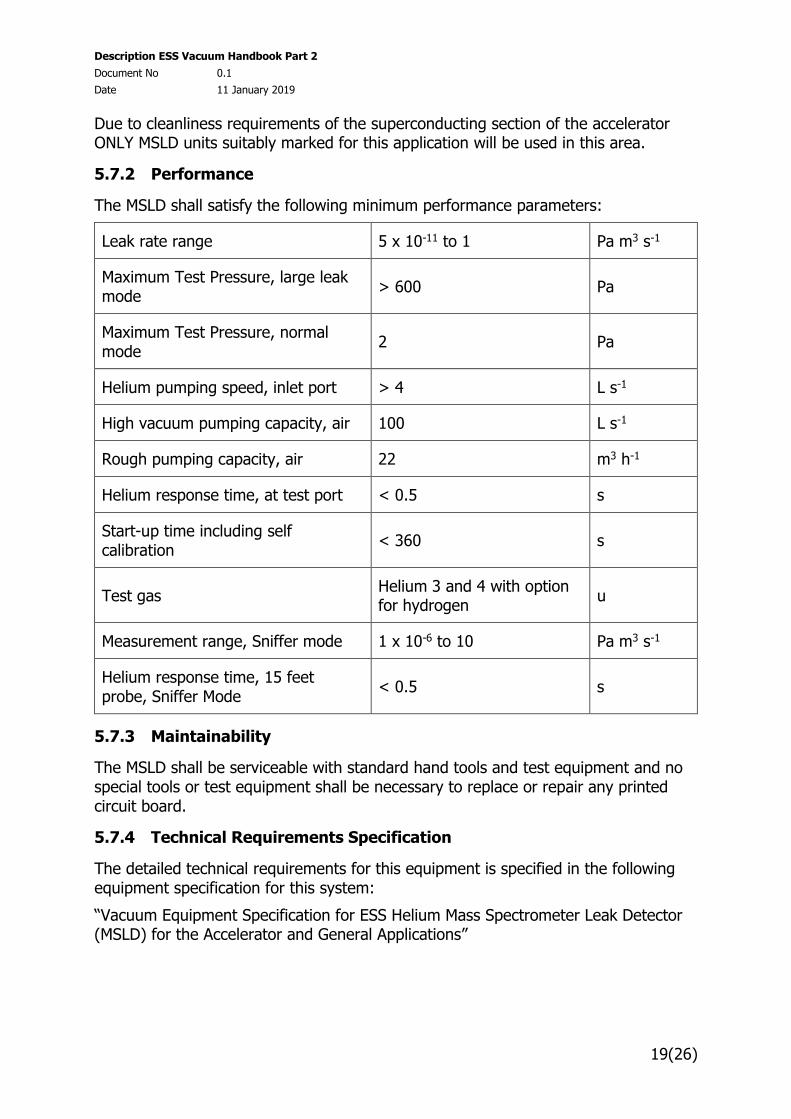
The MSLD shall satisfy the following minimum performance parameters:
Leak rate range 5 x 10-11 to 1 Pa m3 s-1
Maximum Test Pressure, large leak mode
> 600 Pa
Maximum Test Pressure, normal mode
2 Pa
Helium pumping speed, inlet port > 4 L s-1
High vacuum pumping capacity, air 100 L s-1
Rough pumping capacity, air 22 m3 h-1
Helium response time, at test port < 0.5 s
Start-up time including self calibration
< 360 s
Test gas Helium 3 and 4 with option for hydrogen
u
Measurement range, Sniffer mode 1 x 10⁻⁶ to 10 Pa m3 s-1
Helium response time, 15 feet probe, Sniffer Mode
< 0.5 s
5.7.3 Maintainability
The MSLD shall be serviceable with standard hand tools and test equipment and no special tools or test equipment shall be necessary to replace or repair any printed circuit board.
5.7.4 Technical Requirements Specification
The detailed technical requirements for this equipment is specified in the following equipment specification for this system:
“Vacuum Equipment Specification for ESS Helium Mass Spectrometer Leak Detector (MSLD) for the Accelerator and General Applications”
Description ESS Vacuum Handbook Part 2
Document No 0.1
Date 11 January 2019
20(26)
5.8 Residual Gas Analysers
5.8.1 General Requirements
Residual Gas Analysers (RGA) will be used for the measurement of partial pressure (ISO/TS 20175) within a system to characterize the residual gas composition during pump down or any other mode of operation, and in some cases this device will support leak testing.
The RGA will consist of the measurement head and combined controller/ display unit that shall be rack mountable. The controller shall be suitable for being located remotely from the head at distances of up to 100m.
The RGA controller shall be able to communicate, via an Ethernet communication link, with the facilities central control system.
5.8.2 Performance
5.8.2.1 Mass Range
The RGA shall provide a mass range from 1 to 100 amu.
5.8.2.2 Minimum Detectable Partial Pressure
The RGA shall have a minimum detectable partial pressure of 1 x 10-12 Pa (1 x 10-14 mbar).
5.8.2.3 Resolution
The RGA shall provide a resolution of < 0.5 amu @ 10% peak height.
5.8.2.4 Stability
Mass stability shall not be less than +/- 0.1 amu during an eight (8) hour period, after a 30 minute warm-up, when the temperature change is < 5°C. During this period the variation in peak height shall not exceed 2%.
5.8.2.5 Ion Source Materials and Construction
The ion source shall have two independent filaments made of thoria-coated iridium.
5.8.2.6 Analyzer (Gauge) Head Construction
The analyzer head shall be mounted on a 300 series stainless steel CF 40 DN flange or equivalent. No part of the ionizer head or mass filter shall protrude past the mounting flange.
5.8.2.7 Analyzer Head Orientation
The analyzer head shall be suitable for installation and operational in any orientation.
1.1.2 Technical Requirements Specification
The detailed technical requirements for this equipment is specified in the following equipment specification for this system:
“Vacuum Equipment Specification for ESS Residual Gas Analysers (RGA) for the Accelerator and General Applications”

Description ESS Vacuum Handbook Part 2
Document No 0.1
Date 11 January 2019
21(26)
5.9 Mobile Pumping Carts
Mobile pumping carts will be used for a variety of purposes on the accelerator, target and neutron instrument including choppers, neutron guides, etc.
Mobile Pumping Carts (MPC) will be connected via an isolation valve to the main vacuum system when needed.
Some MPC’s will be connected via a manual valve without interlocks while other units will be interlocked through an isolation valve via an electrical connector where the system and pump cart pressures will be used as a valve interlock.
MPC shall be procured against specific equipment technical specifications developed for the procurement by the VG.
The detailed technical requirements for this equipment is specified in the following equipment specification for this system:
“Vacuum Equipment Specification for ESS Mobile Pumping Cart for the Accelerator and General Applications”
“Vacuum Equipment Specification for ESS Mobile Pumping Cart for the superconducting section of the accelerator”
6. Standard Vacuum Equipment
6.1 Flange Sealing Systems
The sealing systems used will generally be dictated by the operating pressure regime, with metal sealing for high vacuum and UHV applications and elastomer sealing for rough and some high vacuum applications. In addition, environmental considerations that could have an influence on the sealing system selected, e.g. radiation levels, operating temperature, etc. may influence the choice made.
Material used for flanges are generally stainless steel: DIN 1.4301 (AISI 304), DIN 1.4306 (AISI 304L) DIN 1.4401 (AISI 316), DIN 1.4404 (AISI 316L) or DIN 1.4429-ESR (AISI 316LN) where low magnetic permeability < 1.005 is required. For some rough vacuum applications other materials are available and may be suitable. Please consult the VG for recommendations regarding the use of alternate materials.
6.1.1 Flange Types
6.1.1.1 ISO clamped-type Flanges
These flanges use a wedge design to apply the seal force through a clamping ring or chain clamp to a seal that is incorporated into a centring ring (ISO 2861 and ISO 1609). The seal is typically an elastomer although metal seals of indium are available but require the use of a chain clamp to apply the additional seal pressure needed. Only indium seals shall be used for high vacuum and UHV applications.
Description ESS Vacuum Handbook Part 2
Document No 0.1
Date 11 January 2019
22(26)
6.1.1.2 ISO bakable knife-edge flanges (Conflat style - CF)
These flanges shall conform to standard dimensions (ISO/ TS 3669-2) and are available in sizes up to 400mm tube diameter. These flanges are the preferred type for high vacuum and UHV applications.
The bolt tighten sequence shall be in a star pattern to ensure even compression of the sealing gasket. Bolts shall be tightened to finger tight and progressively tightened one turn at a time until the design torque values are reached.
For trial assemblies and initial leak testing the copper seal gasket may be substituted with an elastomer seal.
6.1.1.3 ISO-K and ISO-F flanges (63mm up to typically 630mm)
These flanges use either parallel sealing surfaces for sealing with a centring ring (ISO 2861) or metal gasket (diamond type aluminium seal) or contain a seal groove for either metal (Helicoflex type seals) or elastomer O-ring sealing where the clamping of the sealing surfaces is applied by claw clamps (ISO-K) or bolts (ISO-F). Only metal seals shall be used for high vacuum and UHV applications.
The sealing principle of the Helicoflex type seal is based upon the plastic deformation of a jacket of greater ductility than the flange materials. This occurs between the sealing face of a flange and an elastic core composed of a close-wound helical spring. The spring is selected to have a specific compression resistance. During compression, the resulting specific pressure forces the jacket to yield and fill the flange imperfections while ensuring positive contact with the flange sealing faces. Each coil of the helical spring acts independently and allows the seal to conform to surface irregularities on the flange surface. Surface tolerances and surface finish are important for obtaining a good sealing.
6.1.1.4 Other Flanges
Metal gasket face seals are suitable for both high vacuum and UHV applications. These sealing systems are typically available up to 18mm and are used primarily for pipe connections. Swagelok being the most common type of fitting used.
Wire sealed flanges: An OFHC copper wire shall be used to affect the seal. They are available for tube sizes up to 630mm but are not commonly used.
Flanges form EVAC (ISO-CeFiX®) or MKT use a similar sealing arrangement as CF flanges but the sealing pressure is applied through a wedge design with a chain clamp used to apply the pressure to the seal. These sealing systems are available up to 250mm tube size. The use of the chain clamp makes them suitable for applications in radiation areas where the time required to make the vacuum connection can be significantly reduced compared to CF. Further the connection can be made remotely by the use of long handled tools.
6.1.2 Sealing
6.1.2.1 Metal Seals
Metal seals shall be OHFC copper where possible and shall only be used one time before being discarded.
Description ESS Vacuum Handbook Part 2
Document No 0.1
Date 11 January 2019
23(26)
For Helicoflex type seal consult the manufactures catalog for material selection and confirm the suitability of this selection with the VG.
6.1.2.2 Elastomer Seals
Under normal circumstances Fluoroelastomer (FKM - Viton) O-rings should be selected and these are suitable for use up to a temperature of 150°C.
If a higher temperature is required select Perfluoroelastomer (FFKM - Kalrez or Chemraz) which is suitable up to 200 - 250°C
If additional radiation resistance is required, select EDPM (ethylene propylene diene monomer), which is suitable for radiation levels up to 1 MGy compared to Viton, which is suitable up to 0.5 MGy.
6.1.3 Fasteners
Fasteners shall be made of AISI 304 or equivalent or AISI 316LN-ESR when magnetic permeability is an issue.
The bolts used shall be silver plated to prevent the potential for galling (cold welding), with a washer under the head of the bolt or nut. Greases and oil shall not be used as a thread lubricant.
6.2 Bellows
6.2.1 Hydroformed
A specialized type of die forming that uses a high-pressure hydraulic fluid to press room temperature working sheet material into a die. Hydro formed bellows made up of thin stainless steel AISI series 300 (316L, 347, 321 and 304L) without attached flanges or with internally welded flanges is cleanable and is permitted. Note, however, that they are limited in axial movement and lateral offset in comparison to edge welded bellows. They have a relatively high spring rate and therefore dedicated compression tools are required during installation. Special attention must be taken to the end-pieces of such bellows due to inclusion contents and possible leaks as well as corrosion after welding. Therefore it is recommended to use only multidirectional forged stainless steel AISI 316LN-ESR for the end-pieces.
The use of weld collars is recommended where a third party undertakes the welding to an adjacent component.
Please consult the VG for recommendations regarding the selection and use of hydroformed bellows.
The detailed technical requirements for this equipment is specified in the following equipment specification for this system:
“Vacuum Equipment Specification for ESS Hydroformed Bellows for the Accelerator and General Applications”
6.2.2 Edge-welded
Edge welded bellows are made up of thin stainless steel AISI series 300 (316L, 347, 321 and 304L) diaphragms welded on the inside and outside diameters by means of
Description ESS Vacuum Handbook Part 2
Document No 0.1
Date 11 January 2019
24(26)
laser or micro-plasma to form a series of convolutions. The bellows can be delivered very clean and ready for UHV usage. However, if they get contaminated (e.g. during installation), it is difficult to re-clean them. “ Off-the-shelf” bellows may also be used but they need to be qualified before use. Welded bellows must be capable of maintaining continuous leak-free operation and withstand a minimum of 50 thermal cycles from room temperature to 200°C while under vacuum, for the stroke and offset positions specified. Before being put into operation, each bellows needs to be leak tested by using a mass spectrometer helium leak detector. Beside large axial stokes, these bellows also allow for non-negligible lateral and angular displacements. Further they have a comparable low spring rate and therefore no compression tools are required during installation. It is recommended to specify stainless steel 316L for the bellow material and multidirectional forged AISI 316L-ESR for the end-pieces. The detailed technical requirements for this equipment is specified in the following equipment specification for this system:
“Vacuum Equipment Specification for ESS Edge-welded Bellows for the Accelerator and General Applications”
6.2.3 Electroformed
These bellows are produced by electro-deposition: building thin layers of metal onto a precision-machined mandrel and chemically removing the mandrel afterwards.
Electrodeposited nickel alloy is the standard material (ferromagnetic!) and therefore not suitable for use on the accelerator. Copper, silver and gold are also available either as a surface finish or base metal.
Electroformed Bellows shall be procured against specific equipment technical specifications developed for the procurement by the VG.
7. Applicable Documents
In the case of conflict, with the requirements stated in this VH, the VH shall take precedence. If the requirements of the VH are in conflict with Legislation and/or Regulations then these conflicts are to be brought to the attention of the VGL for resolution.
Applicable standards, literature and units are list in the following sections.
8. Appendix
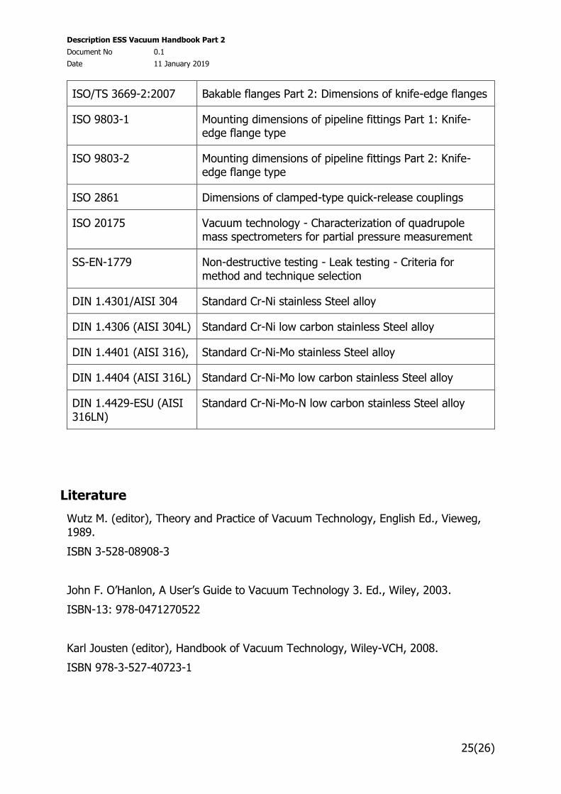
8.1 Standards
Document Description
ISO 15614-1 Arc welding
Description ESS Vacuum Handbook Part 2
Document No 0.1
Date 11 January 2019
25(26)
ISO/TS 3669-2:2007 Bakable flanges Part 2: Dimensions of knife-edge flanges
ISO 9803-1 Mounting dimensions of pipeline fittings Part 1: Knife-edge flange type
ISO 9803-2 Mounting dimensions of pipeline fittings Part 2: Knife-edge flange type
ISO 2861 Dimensions of clamped-type quick-release couplings
ISO 20175 Vacuum technology - Characterization of quadrupole mass spectrometers for partial pressure measurement
SS-EN-1779 Non-destructive testing - Leak testing - Criteria for method and technique selection
DIN 1.4301/AISI 304 Standard Cr-Ni stainless Steel alloy
DIN 1.4306 (AISI 304L) Standard Cr-Ni low carbon stainless Steel alloy
DIN 1.4401 (AISI 316), Standard Cr-Ni-Mo stainless Steel alloy
DIN 1.4404 (AISI 316L) Standard Cr-Ni-Mo low carbon stainless Steel alloy
DIN 1.4429-ESU (AISI 316LN)
Standard Cr-Ni-Mo-N low carbon stainless Steel alloy
Literature
Wutz M. (editor), Theory and Practice of Vacuum Technology, English Ed., Vieweg, 1989.
ISBN 3-528-08908-3
John F. O’Hanlon, A User’s Guide to Vacuum Technology 3. Ed., Wiley, 2003.
ISBN-13: 978-0471270522
Karl Jousten (editor), Handbook of Vacuum Technology, Wiley-VCH, 2008.
ISBN 978-3-527-40723-1
Description ESS Vacuum Handbook Part 2
Document No 0.1
Date 11 January 2019
26(26)
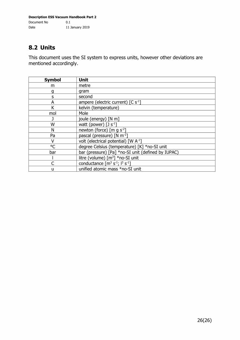
8.2 Units
This document uses the SI system to express units, however other deviations are mentioned accordingly.
Symbol Unit
m metre
g gram
s second
A ampere (electric current) [C s-1]
K kelvin (temperature)
mol Mole
J joule (energy) [N m]
W watt (power) [J s-1]
N newton (force) [m g s-2]
Pa pascal (pressure) [N m-2]
V volt (electrical potential) [W A-1]
°C degree Celsius (temperature) [K] *no-SI unit
bar bar (pressure) [Pa] *no-SI unit (defined by IUPAC)
l litre (volume) [m3] *no-SI unit
C conductance [m3 s-1; l3 s-1]
u unified atomic mass *no-SI unit