Internship report in PTCL, WLL department
34
Pakistan Telecommunication Company Limited Internship Completion Report Department Of Wireless Karachi Submitted by: Muhammad Khalid Ansari Student of Sir Syed University of Engineering & Technology, Karachi. Internship letter no. TRG.15-66-2011 Submitted to: Mr. Israfeel ES Operation, Wireless-I, Karachi
description
This is the internship report prepared by Muhammad Khalid Ansari. All references are given in last.
Transcript of Internship report in PTCL, WLL department
Pakistan Telecommunication
Company Limited
Internship Completion Report
Department
Of
Wireless Karachi
Submitted by: Muhammad Khalid Ansari
Student of
Sir Syed University of Engineering &
Technology, Karachi.
Internship letter no. TRG.15-66-2011
Submitted to: Mr. Israfeel
ES Operation, Wireless-I, Karachi
2
Executive Summary
This report presents the construction and working of PTCL wireless net-work. There are
a number of techniques to manage a wireless network and the one is adopted according to the
requirement. The technique being used by PTCL is CDMA which is an efficient technique to
handle a wireless network. The network can be widened using latest equipments since the need
of cellular communication is increasing day by day.
3
Contents
Background 4
Introduction 6
Cellular Fundamentals 7
BTS 7
BSC 8
MSC 8
PSTN 8
Communication Using Base Stations 8
A Call from a Mobile 8
A Call to a Mobile 8
Registration 8
Multiple Access Schemes 9
Code Division Multiple Access Scheme 9
CDMA capacity: single-cell case 13
Soft Handoff 14
Power Control 15
RAKE Receiver 15
Code Division Multiple Access Digital Cellular System (IS -95) 16
PTCL Structure 18
WLL (Wireless Local Loop) 19
D.R.S (Digital Radio System) 19
O.F (Optical Fiber) 19
Huawei BTS 3606e 20
BTS 36XX Brief 20
BTS 3606e Cabinet 21
BTS 3606e Functions 21
Specifications of Transmitters 22
BTS 3606e Structure 22
BTS 3606e Logical Structure 23
4
BTS 3606e Baseband Subsystem 23
BTS 3606e RF Subsystem 24
Connections of RF Subsystem 25
Power Supply Subsystem 25
Huawei BTS 3900 26
Components 26
BTS3900 Cabinet 27
BTS3900 Cabinet Structure 27
BTS 3900 Hardware consists of 27
Important Points 28
Call types 29
Conclusion 32
References 33
5
Background
Wireless communications is, by any measure, the fastest growing segment of the
communications industry. Cellular systems have experienced exponential growth over the last
decade and there are currently around many billion users worldwide. Indeed, cellular phones
have become a critical business tool and part of everyday life in most developed countries, and
are rapidly supplanting antiquated wire line systems in many developing countries. [1]
Wireless communication is one of the most vibrant areas in the communication field
today. While it has been a topic of study since the 1960s, the past decade has seen a surge of
research activities in the area. The research thrust in the past decade has led to a much richer set
of perspectives and tools on how to communicate over wireless channels, and the picture is still
very much evolving. [2]
Guglielmo Marconi invented the wireless telegraph in 1896.1 In 1901, he sent telegraphic
signals across the Atlantic Ocean from Cornwall to St. John's Newfoundland; a distance of about
3200 km. His invention allowed two parties to communicate by sending each other alphanumeric
characters encoded in an analog signal. Over the last century, advances in wireless technologies
have led to the radio, the television, the mobile telephone, and communications satellites. All
types of information can now be sent to almost every corner of the world. Recently, a great deal
of attention has been focused on satellite communications, wireless networking, and cellular
technology.
The cellular or mobile telephone is the modern equivalent of Marconi's wireless
telegraph, offering two-party, two-way communication. The first-generation wireless phones
used analog technology. These devices were heavy and coverage was patchy, but they
successfully demonstrated the inherent convenience of mobile communications. The current
generation of wireless devices is built using digital technology. Digital networks carry much
more traffic and provide better reception and security than analog networks. In addition, digital
technology has made possible value-added services such as caller identification. Newer wireless
devices connect to the Internet using frequency ranges that support higher information rates.
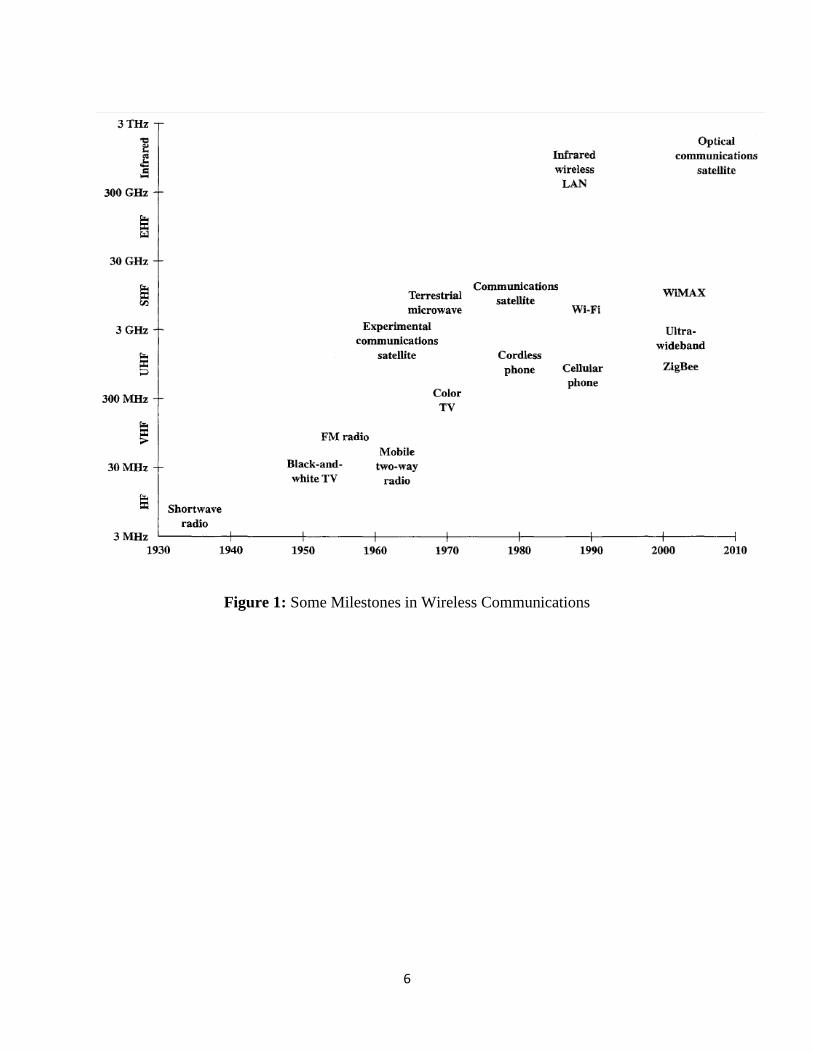
Figure 1 highlights some of the key milestones in the development of wireless
communications. Wireless technologies have gradually migrated to higher frequencies. Higher
frequencies enable the support of greater data rates and throughput. [
6
Figure 1: Some Milestones in Wireless Communications

7
Introduction
The earliest wireless networks used analog communication. The first cellular networks to
be developed were analog. The analog networks are often referred to as “first-generation”
cellular networks; the currently deployed digital networks are referred to as “second-generation”
networks. There are three principal types of second-generation networks in operation throughout
the world: GSM, D-AMPS or IS-136, and IS-95 or CDMA. [4]
PTCL is using Code-division multiple access (CDMA) principle for its V-fone and
eVo wireless broadband services. CDMA is the third type of multiple access technique used in
cellular systems. It is the access technique used in the second-generation system IS-95. [5].
CDMA is one of spread spectrum multiple access techniques.
Spread spectrum multiple access uses signals which have a transmission bandwidth that
is several orders of magnitude greater than the minimum required RF bandwidth. A pseudo-noise
(PN) sequence converts a narrowband signal to a wideband noise-like signal before transmission.
Many users can share the same spread spectrum bandwidth without interfering with one another.
There are two main types of spread spectrum multiple access techniques; frequency hopped
multiple access (FH) and direct sequence multiple access (DS). Direct sequence multiple access
is also called code division multiple access (CDMA).
In code division multiple access (CDMA) systems, the narrowband message signal is
multiplied by a very large bandwidth signal called the spreading signal. The spreading signal is a
pseudo-noise code sequence that has a chip rate which is orders of magnitudes greater than the
data rate of the message. All users in a CDMA system use the same carrier frequency and may
transmit simultaneously. Each user operates independently with no knowledge of the other users.
[6]. Thus, not only all users in the same cell share all the time-frequency degrees of freedom, so
do the users in different cells. Universal frequency reuse is a key property of CDMA systems.
[7]. CDMA with different forms of multiuser detection achieves the Shannon capacity of both
the uplink and the downlink, although the capacity-achieving transmission and reception
strategies for the two channels are very different. Finally, it is simple to allocate multiple
channels to one user with CDMA by assigning that user multiple codes. CDMA is used for
multiple access in the IS-95 digital cellular standards. [8]
8
Cellular Fundamentals
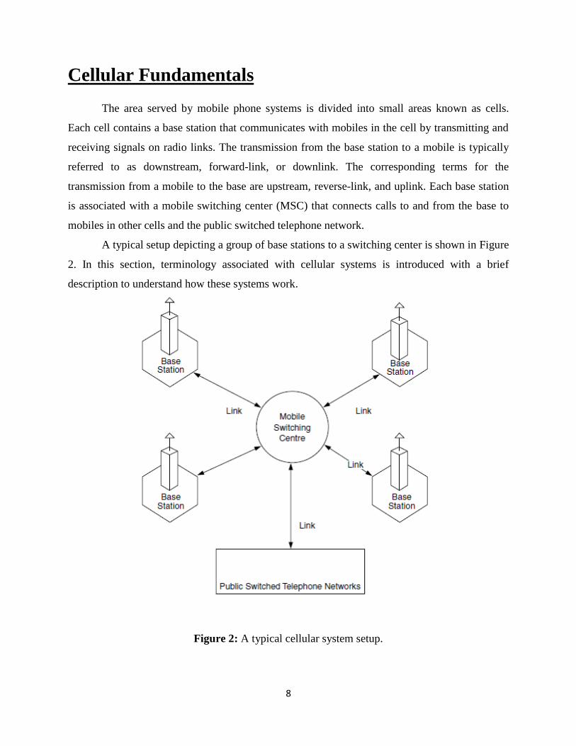
The area served by mobile phone systems is divided into small areas known as cells.
Each cell contains a base station that communicates with mobiles in the cell by transmitting and
receiving signals on radio links. The transmission from the base station to a mobile is typically
referred to as downstream, forward-link, or downlink. The corresponding terms for the
transmission from a mobile to the base are upstream, reverse-link, and uplink. Each base station
is associated with a mobile switching center (MSC) that connects calls to and from the base to
mobiles in other cells and the public switched telephone network.
A typical setup depicting a group of base stations to a switching center is shown in Figure
2. In this section, terminology associated with cellular systems is introduced with a brief
description to understand how these systems work.
Figure 2: A typical cellular system setup.
9
BTS
The Base Transceiver Station houses the radio transceivers that define a cell and handles
the radio-link protocols with the Mobile Station. In a large urban area, there will potentially be a
large number of BTSs deployed, thus the requirements for a BTS are ruggedness, reliability,
portability, and minimum cost.
BSC
The Base Station Controller manages the radio resources for one or more BTS. It handles
radio-channel setup, frequency hopping, and handovers, as described below. The BSC is the
connection between the mobile station and the Mobile service Switching Center (MSC).
MSC
Mobile services Switching Center (MSC). It acts like a normal switching node of the
PSTN or ISDN, and additionally provides all the functionality needed to handle a mobile
subscriber, such as registration, authentication, location updating, handovers, and call routing to
a roaming subscriber.
PSTN
It connects MSC to landline telephones and other mobile networks. Calls for landline and
other mobile networks are routed via PSTN.
Communication Using Base Stations
A base station communicates with mobiles using two types of radio channels, control
channels to carry control information, and traffic channels to carry messages. Each base station
continuously transmits control information on its control channels. When a mobile is switched
on, it scans the control channels and tunes to a channel with the strongest signal. This normally
would come from the base station located in the cell in which the mobile is also located. The
mobile exchanges identification information with the base station and establishes the
authorization to use the network. At this stage, the mobile is ready to initiate and receive a call.
A Call from a Mobile
When a mobile wants to initiate a call, it sends the required number to the base station.
The base station sends this information to the switching center that assigns traffic channel to this
call because the control channels are only used for control information. Once the traffic channel
10
is assigned, this information is relayed to the mobile via the base station. The mobile switches
itself to this channel. The switching center then completes the rest of the call.
A Call to a Mobile
When someone calls a mobile, the call arrives at the mobile switching center. It then
sends a paging message through several base stations. A mobile tuned to a control channel
detects its number in the paging message and responds by sending a response signal to the
nearby base station. The base station informs the switching center about the location of the
desired mobile. The switching center assigns a traffic channel to this call and relays this
information to the mobile via the base. The mobile switches itself to the traffic channel and the
call is complete.
Registration
A mobile is normally located by transmitting a paging message from various base
stations. When a large number of base stations are involved in the paging process, it becomes
impractical and costly. It is avoided by a registration procedure where a roaming phone registers
with an MSC closer to itself. This information may be stored with the switching center of the
area as well as the home switching center of the phone. The home base of the phone is the one
where it is permanently registered. Once a call is received for this phone, its home switching
center contacts the switching center where the phone is currently roaming. Paging in the vicinity
of the previous known location helps to locate the phone. Once it responds, the call may be
connected as discussed previously.
Multiple Access Schemes
The available spectrum bandwidth is shared in a number of ways by various wireless
radio links. The way in which this is done is referred to as a multiple access scheme. There are
basically four principle schemes. These are frequency division multiple access (FDMA), time
division multiple access (TDMA), code division multiple access (CDMA), and space division
multiple access (SDMA). [9]
11
Code Division Multiple Access Scheme
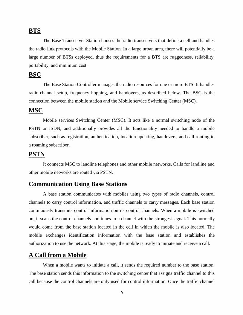
The CDMA scheme is a direct sequence (DS), spread-spectrum method. It uses linear
modulation with wideband pseudo noise (PN) sequences to generate signals. These sequences,
also known as codes, spread the spectrum of the modulating signal over a large bandwidth,
simultaneously reducing the spectral density of the signal. Thus, various CDMA signals occupy
the same bandwidth and appear as noise to each other. [10]
Figure 3: General Model of Spread Spectrum Digital Communication System
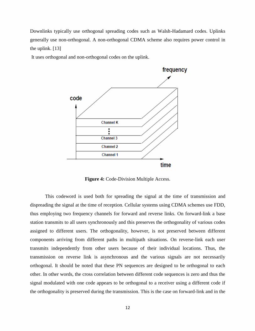
All users in a CDMA system, as seen from Figure 4, use the same carrier frequency and
may transmit simultaneously. Each user has its own pseudorandom codeword which is
approximately orthogonal to all other codeword. The receiver performs a time correlation
operation to detect only the specific desired codeword. All other codeword appear as noise due to
decorrelation. For detection of the message signal, the receiver needs to know the codeword used
by the transmitter. [11]
Each user spreads its signal over the entire bandwidth, such that when demodulating any
particular user’s data, other users’ signals appear as pseudo white noise. [12]
12
Downlinks typically use orthogonal spreading codes such as Walsh-Hadamard codes. Uplinks
generally use non-orthogonal. A non-orthogonal CDMA scheme also requires power control in
the uplink. [13]
It uses orthogonal and non-orthogonal codes on the uplink.
Figure 4: Code-Division Multiple Access.
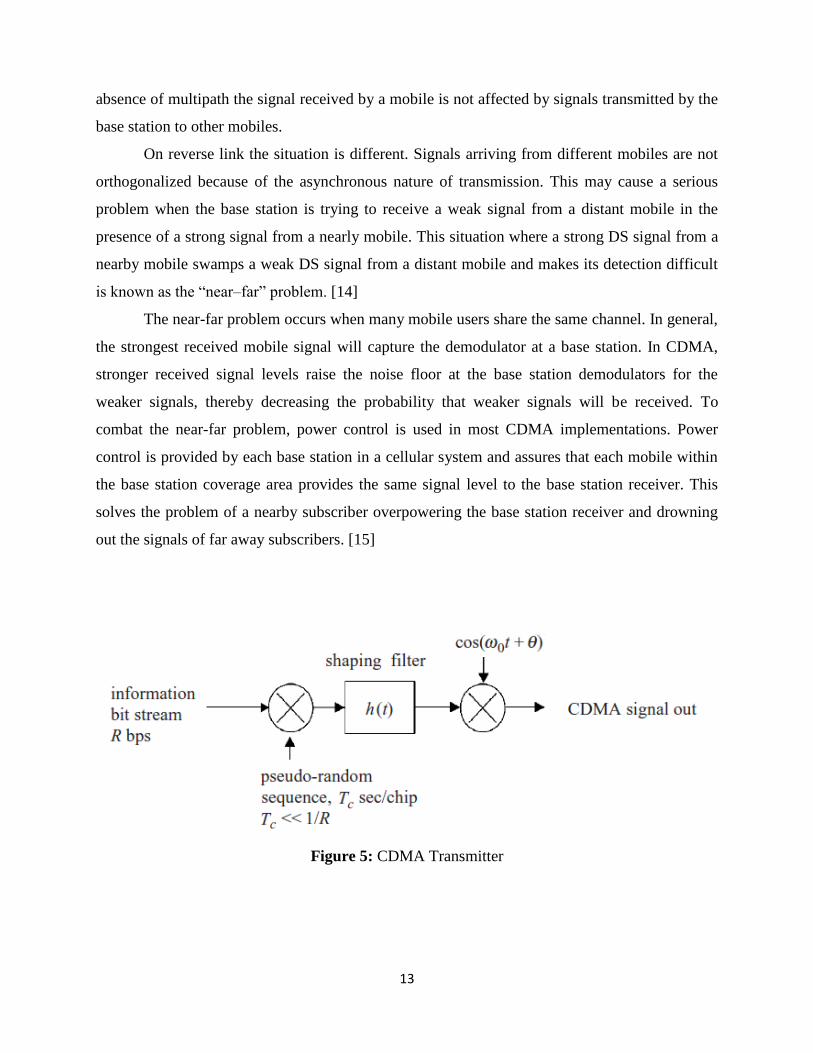
This codeword is used both for spreading the signal at the time of transmission and
dispreading the signal at the time of reception. Cellular systems using CDMA schemes use FDD,
thus employing two frequency channels for forward and reverse links. On forward-link a base
station transmits to all users synchronously and this preserves the orthogonality of various codes
assigned to different users. The orthogonality, however, is not preserved between different
components arriving from different paths in multipath situations. On reverse-link each user
transmits independently from other users because of their individual locations. Thus, the
transmission on reverse link is asynchronous and the various signals are not necessarily
orthogonal. It should be noted that these PN sequences are designed to be orthogonal to each
other. In other words, the cross correlation between different code sequences is zero and thus the
signal modulated with one code appears to be orthogonal to a receiver using a different code if
the orthogonality is preserved during the transmission. This is the case on forward-link and in the
13
absence of multipath the signal received by a mobile is not affected by signals transmitted by the
base station to other mobiles.
On reverse link the situation is different. Signals arriving from different mobiles are not
orthogonalized because of the asynchronous nature of transmission. This may cause a serious
problem when the base station is trying to receive a weak signal from a distant mobile in the
presence of a strong signal from a nearly mobile. This situation where a strong DS signal from a
nearby mobile swamps a weak DS signal from a distant mobile and makes its detection difficult
is known as the “near–far” problem. [14]
The near-far problem occurs when many mobile users share the same channel. In general,
the strongest received mobile signal will capture the demodulator at a base station. In CDMA,
stronger received signal levels raise the noise floor at the base station demodulators for the
weaker signals, thereby decreasing the probability that weaker signals will be received. To
combat the near-far problem, power control is used in most CDMA implementations. Power
control is provided by each base station in a cellular system and assures that each mobile within
the base station coverage area provides the same signal level to the base station receiver. This
solves the problem of a nearby subscriber overpowering the base station receiver and drowning
out the signals of far away subscribers. [15]
Figure 5: CDMA Transmitter
14
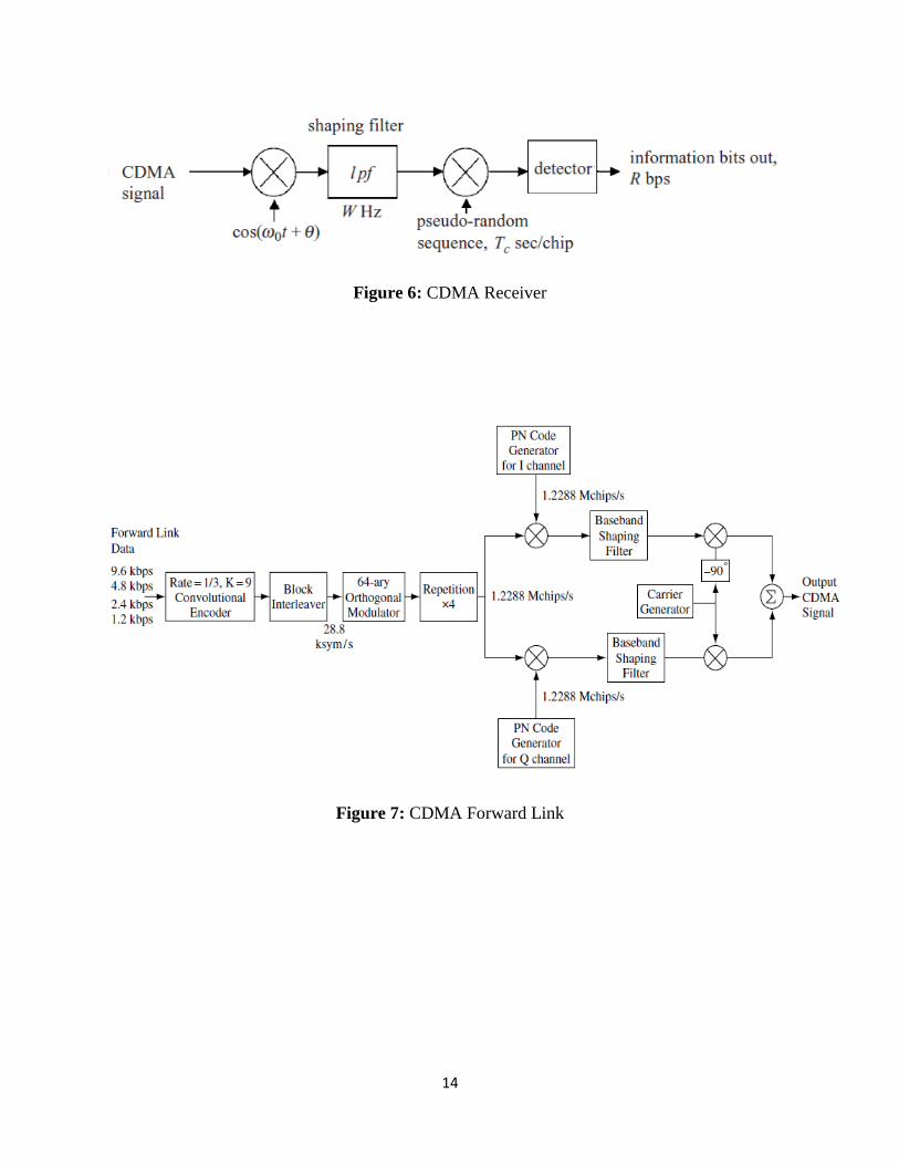
Figure 6: CDMA Receiver
Figure 7: CDMA Forward Link
15
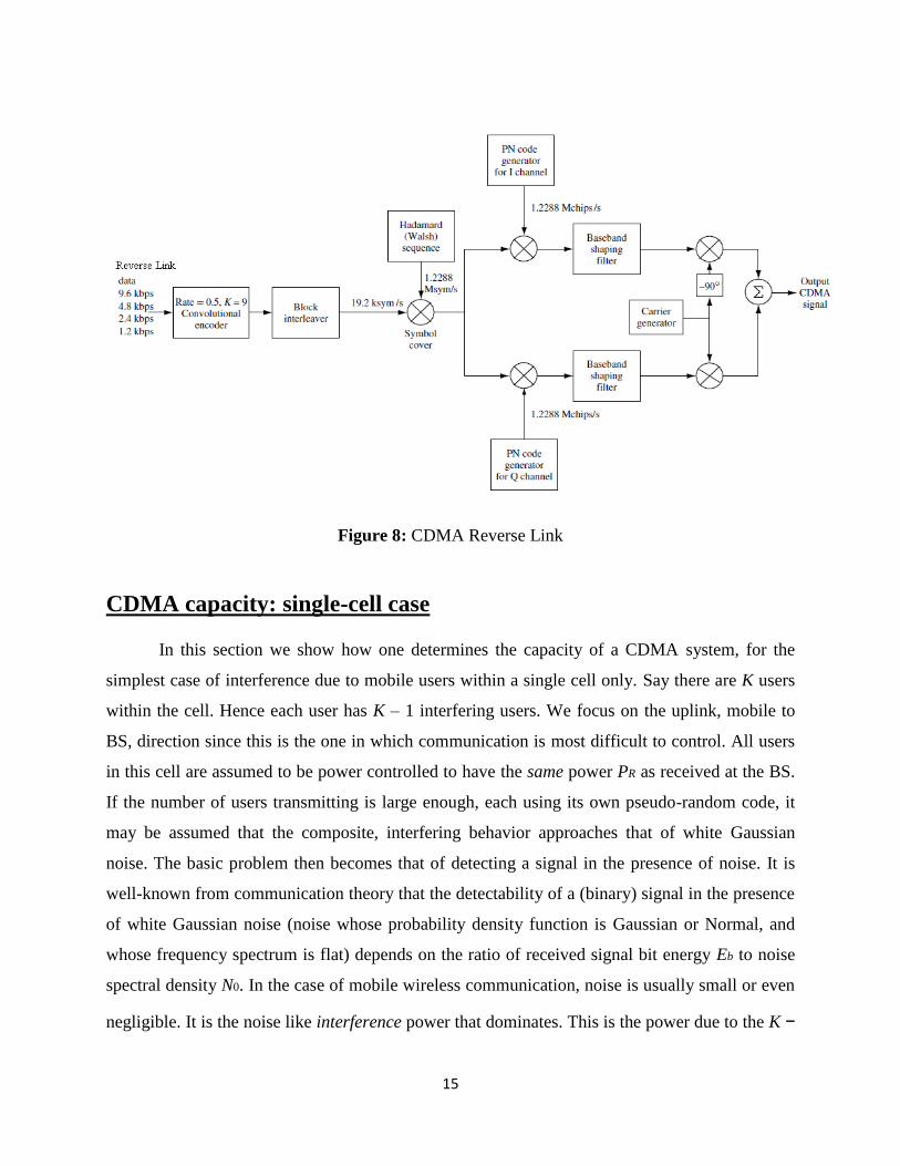
Figure 8: CDMA Reverse Link
CDMA capacity: single-cell case
In this section we show how one determines the capacity of a CDMA system, for the
simplest case of interference due to mobile users within a single cell only. Say there are K users
within the cell. Hence each user has K – 1 interfering users. We focus on the uplink, mobile to
BS, direction since this is the one in which communication is most difficult to control. All users
in this cell are assumed to be power controlled to have the same power PR as received at the BS.
If the number of users transmitting is large enough, each using its own pseudo-random code, it
may be assumed that the composite, interfering behavior approaches that of white Gaussian
noise. The basic problem then becomes that of detecting a signal in the presence of noise. It is
well-known from communication theory that the detectability of a (binary) signal in the presence
of white Gaussian noise (noise whose probability density function is Gaussian or Normal, and
whose frequency spectrum is flat) depends on the ratio of received signal bit energy Eb to noise
spectral density N0. In the case of mobile wireless communication, noise is usually small or even
negligible. It is the noise like interference power that dominates. This is the power due to the K −
16
1 interfering users, given by (K – 1)*PR. We thus use the signal bit energy to interference noise
power spectral density as a measure of signal detectability.
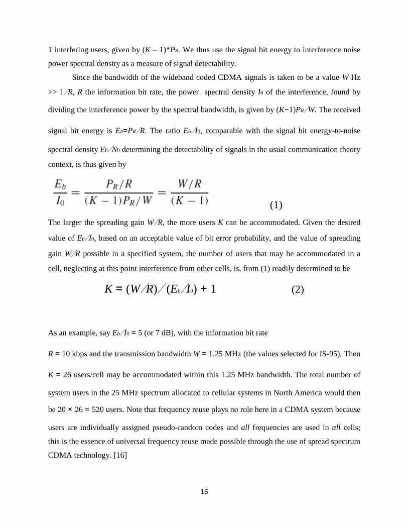
Since the bandwidth of the wideband coded CDMA signals is taken to be a value W Hz
>> 1/R, R the information bit rate, the power spectral density I0 of the interference, found by
dividing the interference power by the spectral bandwidth, is given by (K−1)PR/W. The received
signal bit energy is Eb=PR/R. The ratio Eb/I0, comparable with the signal bit energy-to-noise
spectral density Eb/N0 determining the detectability of signals in the usual communication theory
context, is thus given by
(1)
The larger the spreading gain W/R, the more users K can be accommodated. Given the desired
value of Eb/I0, based on an acceptable value of bit error probability, and the value of spreading
gain W/R possible in a specified system, the number of users that may be accommodated in a
cell, neglecting at this point interference from other cells, is, from (1) readily determined to be
K = (W/R)/ (Eb/I0) + 1 (2)
As an example, say Eb/I0 = 5 (or 7 dB), with the information bit rate
R = 10 kbps and the transmission bandwidth W = 1.25 MHz (the values selected for IS-95). Then
K = 26 users/cell may be accommodated within this 1.25 MHz bandwidth. The total number of
system users in the 25 MHz spectrum allocated to cellular systems in North America would then
be 20 × 26 = 520 users. Note that frequency reuse plays no role here in a CDMA system because
users are individually assigned pseudo-random codes and all frequencies are used in all cells;
this is the essence of universal frequency reuse made possible through the use of spread spectrum
CDMA technology. [16]

17
Universal frequency reuse means that users in all cells get the full bandwidth or degrees of
freedom of the system. [17]
Soft Handoff
In CDMA systems, since all the cells share the same spectrum, soft handoffs are possible:
multiple base-stations can simultaneously decode the mobile’s data, with the switching center
choosing the best reception among them (Figure 9). Soft handoffs provide another level of
diversity to the users.
Figure 9: Soft Handoff
In the process of soft handoff, the mobile is able to communicate with more than one
base station. It receives signals from more than one base station and the received signals are
combined after appropriate delay adjustment. Similarly, more than one station receives signals
from mobiles and the network combines different signals. This scheme is also known as
macroscopic diversity and is mostly employed by CDMA systems.
18
The soft handoff process is mobile-initiated and works like this. While a user is tracking
the downlink pilot of the cell it is currently in, it can be searching for pilots of adjacent cells
(these pilots are known pseudo-noise sequences shifted by known offsets). In general, this
involves timing acquisition of the adjacent cell as well. Since, timing acquisition is a
computationally very expensive step. Thus, a practical alternative is for the base-station clocks to
be synchronized so that the mobile only has to acquire timing once. Once a pilot is detected and
found to have sufficient signal strength relative to the first pilot, the mobile will signal the event
to its original base-station. The original base-station will in turn notify the switching center,
which enables the second cell’s base-station to both send and receive the same traffic to and from
the mobile. In the uplink, each base-station demodulates and decodes the frame or packet
independently, and it is up to the switching center to arbitrate. Normally, the better cell’s
decision will be used. [18]
Power Control
It is important that a radio receiver receives a power level that is enough for its proper
function but not high enough for this level to disturb other receivers. This is achieved with
maintaining constant power level at the receiver by transmitter power control. The receiver
controls the power of the transmitter at the other end. For example, a base would control the
power transmitted by mobile phones and vice versa.
It is done by a receiver monitoring its received power and sending a control signal to the
transmitter to control its power transmission as required. Sometimes a separate pilot signal is
used for this purpose. [19]
Power control is implemented at the base station by rapidly sampling the radio signal
strength indicator (RSSI) levels of each mobile and then sending a power change command over
the forward radio link. Despite the use of power control within each cell, out-of-cell mobiles
provide interference which is not under the control of the receiving base station. [20]
Power control reduces the near–far problem in CDMA systems and helps to minimize the
interference near the cell boundaries when used in forward-link. [21]
19
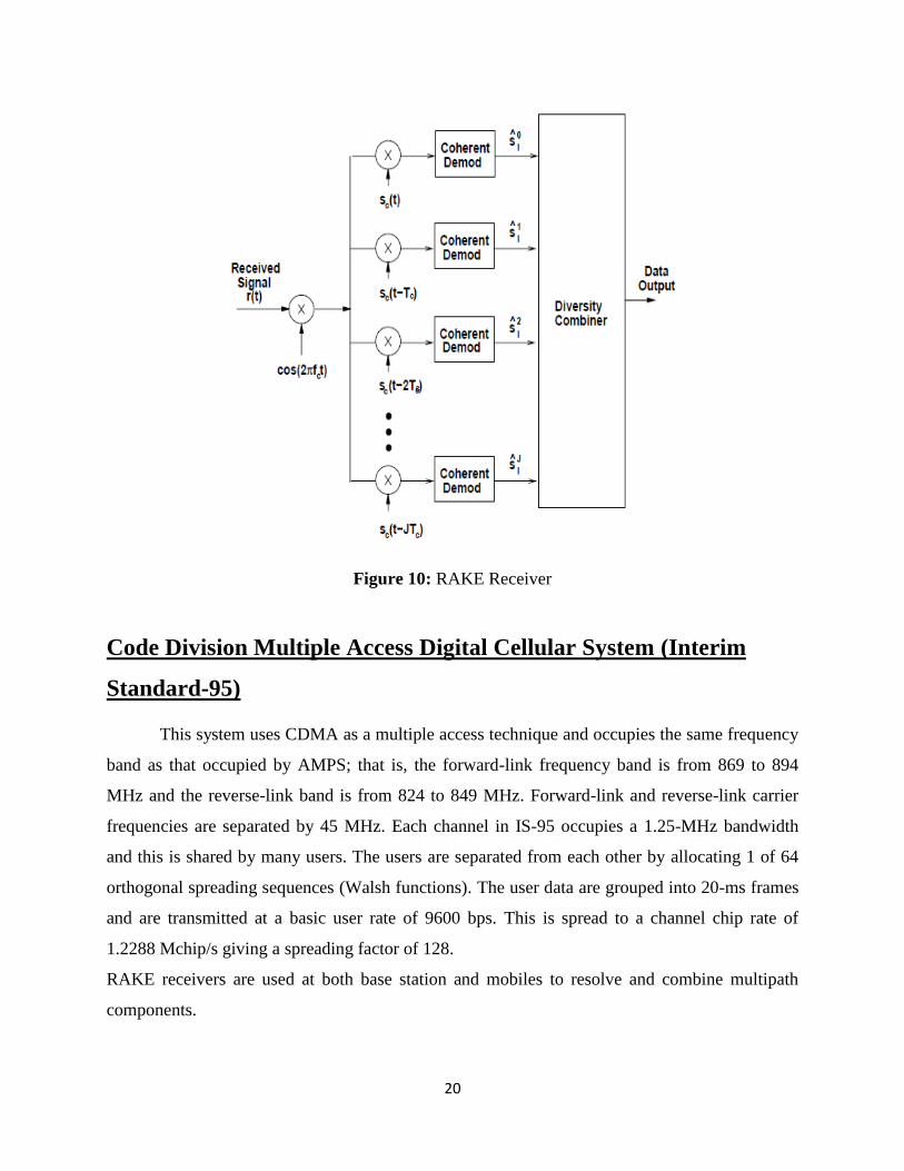
RAKE Receiver
In CDMA spread spectrum systems, the chip rate is typically much greater than the flat
fading bandwidth of the channel. Whereas conventional modulation techniques require an
equalizer to undo the inter symbol interference (ISI) between adjacent symbols, CDMA
spreading codes are designed to provide very low correlation between successive chips. Thus,
propagation delay spread in the radio channel merely provides multiple versions of the
transmitted signal at the receiver. If these multipath components are delayed in time by more
than one chip duration, they appear like uncorrelated noise at a CDMA receiver, and equalization
is not required. However, there is useful information in the multipath components. CDMA
receivers may combine the time delayed versions of the original signal transmission in order to
improve the signal to noise ratio at the receiver. A RAKE receiver does just this. It attempts to
collect the time-shifted versions of the original signal by providing a separate correlation
receiver for each of the multipath signals. The RAKE receiver, shown in Figure 4, is essentially a
diversity receiver designed specifically for CDMA, where the diversity is provided by the fact
that the multipath components are practically uncorrelated from one another when their relative
propagation delays exceed a chip period.
A RAKE receiver utilizes multiple correlators to separately detect the M strongest
multipath components. The outputs of each correlator are weighted to provide a better estimate
of the transmitted signal than is provided by a single component. Demodulation and bit decisions
are then based on the weighted outputs of the M correlators. [22]
20
Figure 10: RAKE Receiver
Code Division Multiple Access Digital Cellular System (Interim
Standard-95)
This system uses CDMA as a multiple access technique and occupies the same frequency
band as that occupied by AMPS; that is, the forward-link frequency band is from 869 to 894
MHz and the reverse-link band is from 824 to 849 MHz. Forward-link and reverse-link carrier
frequencies are separated by 45 MHz. Each channel in IS-95 occupies a 1.25-MHz bandwidth
and this is shared by many users. The users are separated from each other by allocating 1 of 64
orthogonal spreading sequences (Walsh functions). The user data are grouped into 20-ms frames
and are transmitted at a basic user rate of 9600 bps. This is spread to a channel chip rate of
1.2288 Mchip/s giving a spreading factor of 128.
RAKE receivers are used at both base station and mobiles to resolve and combine multipath
components.
21
During handoff the standard allows for base station diversity whereby a mobile keeps
link with both the base stations and combines signals from both the stations to improve signal
quality as it would combine multipath signals.
In forward-link a base station transmits simultaneously to all users using 1 of 64 spreading
sequences for each user once the user data are encoded using a half-rate convolution code and
are interleaved. All signals in a cell are also scrambled using a PN sequence of length 215 to
reduce the co-channel interference. During the scrambling process the orthogonality between
different users is preserved. The forward channel consists of 1 pilot channel, 1 synchronization
channel, up to 7 paging channels, and up to 63 traffic channels. The pilot channel transmits
higher power than other channels and is used by mobiles to acquire timing for forward channel
and to compare signal strength of different base stations. It also provides phase reference for
coherent detection.
The synchronization channel operates at 1200 bps and broadcasts a synchronization
message to mobiles. The paging channels are used to transmit paging messages from the base
station to mobiles and to operate at 9600, 4800, or 2400 bps. The traffic channels support
variable data rate operating at 9600, 4800, 2400, and 1200 bps.
On reverse channels, mobiles transmit asynchronously to the base, and orthogonally
between different users in a cell are not guaranteed. A strict control is applied to the power of
each mobile so that a base station receives constant power from each user, thus eliminating the
near–far problem. Power control command is sent by the base to mobiles at a rate of 800 bps.
The reverse channels are made up of access channels and reverse traffic channels. The reverse
channels contain up to 32 access channels per paging channel, operate at 4800 bps, and are used
by mobiles to initiate communication with base and to respond to paging messages. The reverse
traffic channel is a variable data rate channel and operates similar to the forward channels at
9600, 4800, 2400, and 1200 bps. [23]
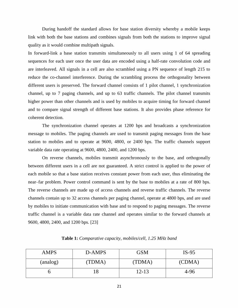
Table 1: Comparative capacity, mobiles/cell, 1.25 MHz band
AMPS D-AMPS GSM IS-95
(analog) (TDMA) (TDMA) (CDMA)
6 18 12-13 4-96
22
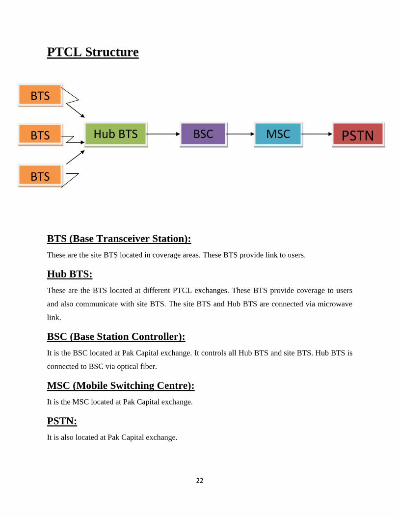
PTCL Structure
BTS (Base Transceiver Station):
These are the site BTS located in coverage areas. These BTS provide link to users.
Hub BTS:
These are the BTS located at different PTCL exchanges. These BTS provide coverage to users
and also communicate with site BTS. The site BTS and Hub BTS are connected via microwave
link.
BSC (Base Station Controller):
It is the BSC located at Pak Capital exchange. It controls all Hub BTS and site BTS. Hub BTS is
connected to BSC via optical fiber.
MSC (Mobile Switching Centre):
It is the MSC located at Pak Capital exchange.
PSTN:
It is also located at Pak Capital exchange.
BTS
BTS
BTS
Hub BTS BSC MSC PSTN
23
WLL (Wireless Local Loop):
Wireless local loop (WLL), is a term for the use of a wireless communications link as
the "last mile / first mile" connection for delivering plain Old Telephone Service (POTS)
and/or broadband Internet to telecommunications customers. [24]. WLL is a system that connects
subscribers to the local telephone station wirelessly. It is an emerging access network technology
based on CDMA principle. This technology is useful for providing cost effective mobile services
and wireless telephone connection in areas where provision of landline telephone connection is
not feasible or where demand for mobile phones is very high.
There are two media of communication
D.R.S (Digital Radio System):
It is an unguided medium. It is used to communicate between site BTS and Hub BTS.
O.F (Optical Fiber):
It is a guided medium. It is used to transfer data from Hub BTS to BSC. Since Hub BTS
has many BTS data as well as PSTN data, it needs more medium bandwidth to send data which
cannot be achieved by DRS.
D.R.S elements
O.D.U (Outdoor Unit) ---capacity dependent
I.D.U (Indoor Unit) ---frequency dependent
I.F cable (Intermediate Frequency)
ODU is connected to parabolic dish. If you have more than one dish then we will connect ODU
alternatively, one horizontal and one vertical.
ODU consists of power amp, crystal oscillator.
ODU is connected to IDU through I.F cable
Polarization is very important
Vertical polarization is best.
Waves are transmitted by reflection, refraction and diffraction.
IDU does modulation and demodulation.
NEC equipments are best in world.
24
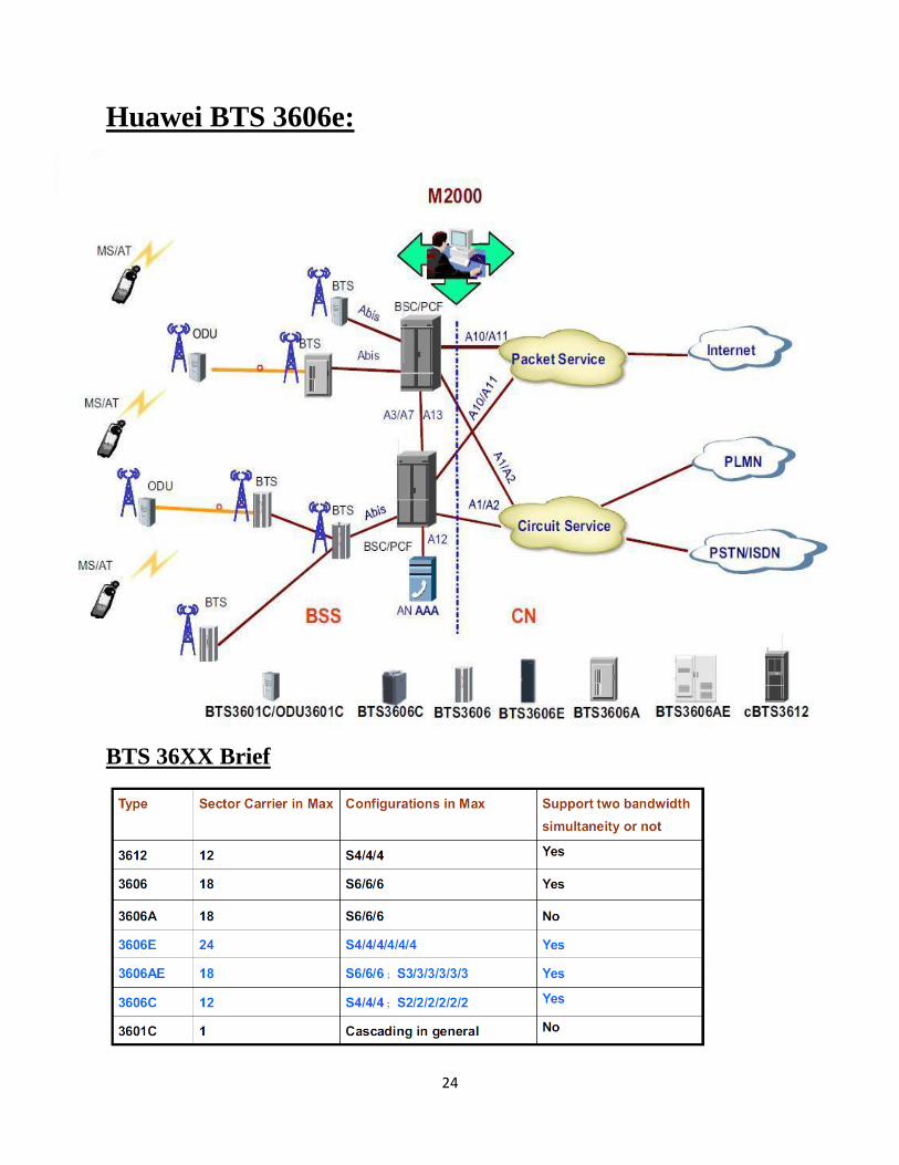
Huawei BTS 3606e:
BTS 36XX Brief
25
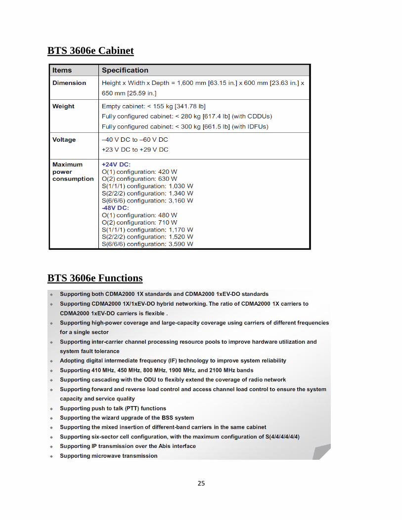
BTS 3606e Cabinet
BTS 3606e Functions

26
Specifications of Transmitters
BTS 3606e Structure
IDFU/CDDU
Baseband subrack RF subrack
Power Supply subrack
27
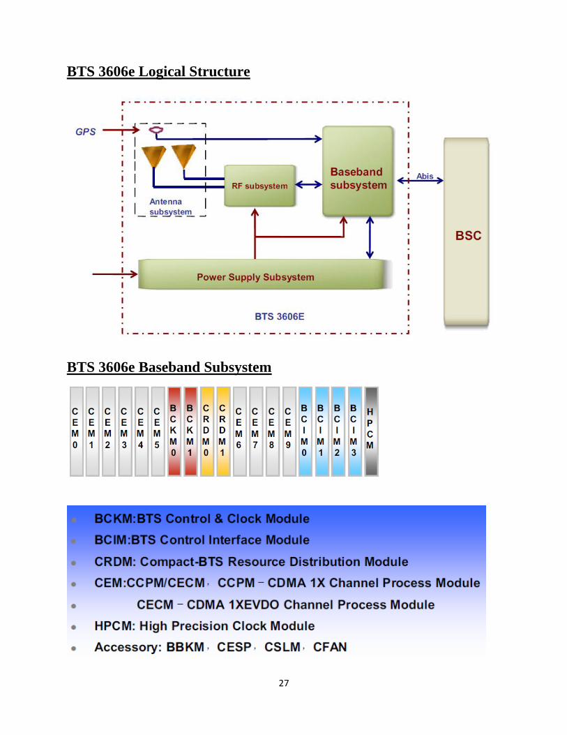
BTS 3606e Logical Structure
BTS 3606e Baseband Subsystem
28
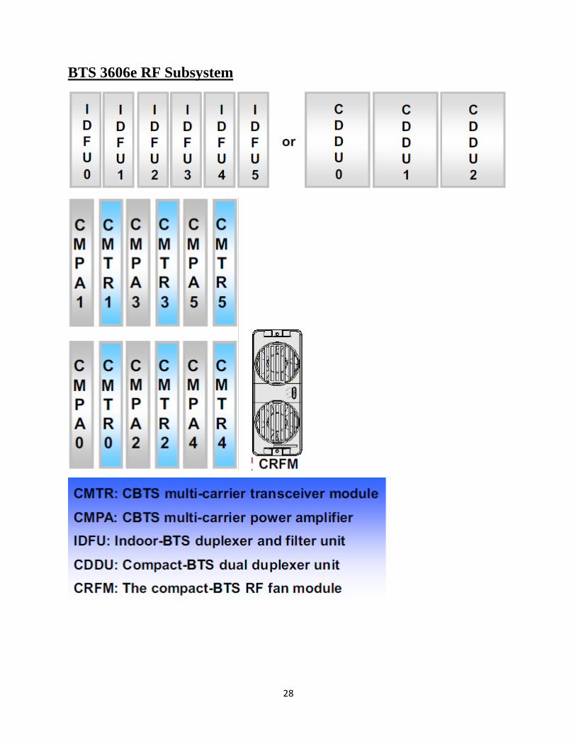
BTS 3606e RF Subsystem
29
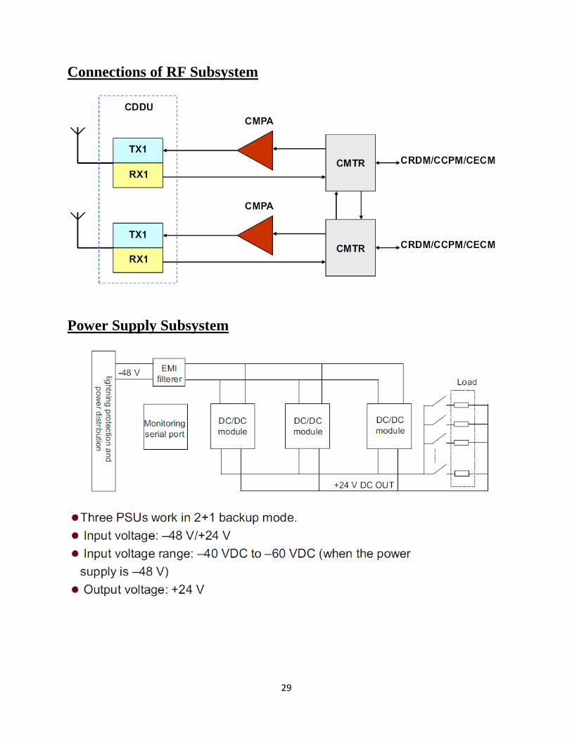
Connections of RF Subsystem
Power Supply Subsystem
30
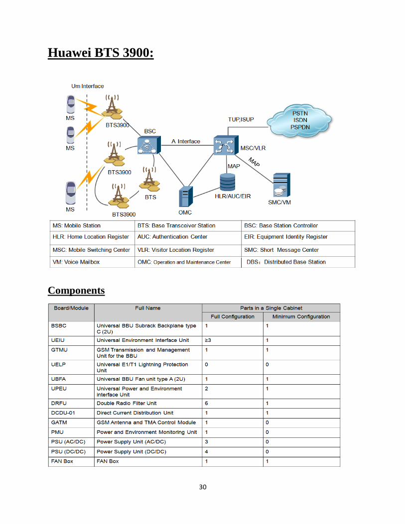
Huawei BTS 3900:
Components
31
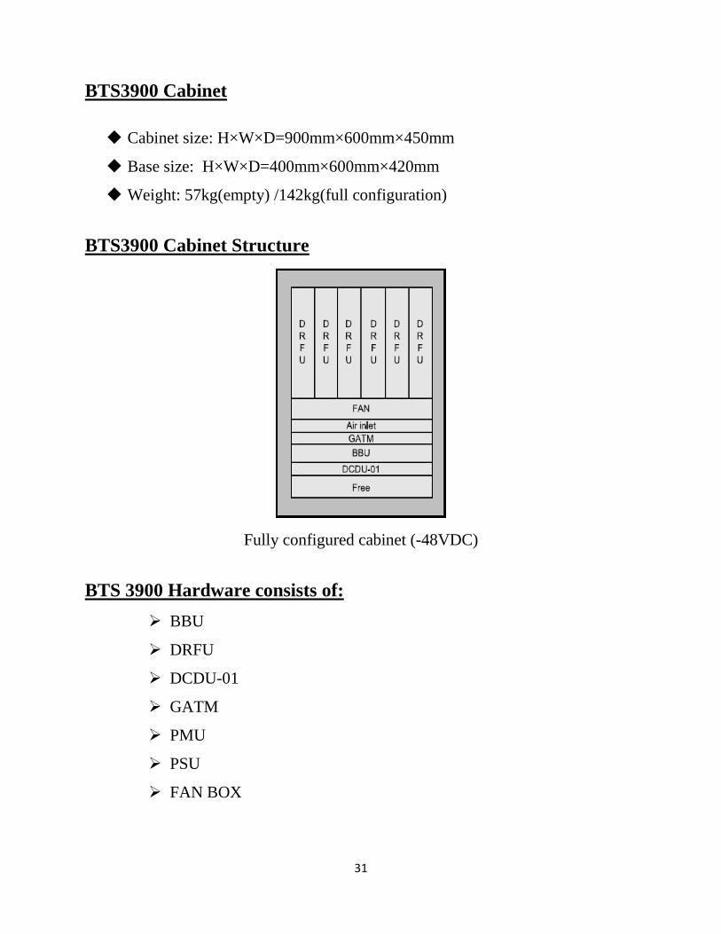
BTS3900 Cabinet
Cabinet size: H×W×D=900mm×600mm×450mm
Base size: H×W×D=400mm×600mm×420mm
Weight: 57kg(empty) /142kg(full configuration)
BTS3900 Cabinet Structure
Fully configured cabinet (-48VDC)
BTS 3900 Hardware consists of:
BBU
DRFU
DCDU-01
GATM
PMU
PSU
FAN BOX
32
The BBU3900 boards consist of the BSBC, UEIU, GTMU, and UELP; the BBU3900
modules consist of the UBFU and the UPEU.
The BSBC is the backplane of the BBU. The BSBC provides eight board slots,
two power slots, and one fan slot.
The universal environment interface unit (UEIU) supports multiple environment
monitoring signals. The UEIU supports eight Boolean alarm signals and two
RS485 environment monitoring signals.
The GSM transmission, timing, and management unit for BBU (GTMU) controls
and manages the entire BTS. It provides interfaces related to the reference clock,
power supply, OM, and external alarm collection.
The universal E1/T1 lightning protection unit (UELP) provides lightning
protection for four E1/T1 signals.
The universal BBU fan unit type A (2U) (UBFU) communicates with the GTMU
to regulate the temperature, adjust the fan speed, and report alarms. The UBFA
module is hot swappable.
The universal power and environment interface unit (UPEU) supports the –48V/
+24V DC power input, supplies power to the boards, modules, and fan in the
BBU, and provides access to multiple environment monitoring signals.
The DRFU performs modulation and demodulation between baseband signals and
RF signals, processes data, and combines and divides signals.
The direction current distribution unit (DCDU-01) provides -48V DC power of 10
outputs.
The GSM antenna and TMA control module (GATM) is a module that controls the
antenna and TMA. The GATM is optional.
The direction current distribution unit (DCDU-01) provides -48V DC power of 10
outputs.
The PMU manages the power supply and batteries. The PMU is the core of the
power monitoring system.
The fan box regulates the temperature at the air inlet of the cabinet and in the fan
box. It can adjust the rotation speed of the fans to implement ventilation and
dissipation for the cabinet. [25]
33
Conclusion
The aim of the internship was to gain the knowledge of working of PTCL wireless
services. It is known that PTCL wireless network services, V-fone and eVo wireless broadband
internet, is working on CDMA principle. CDMA has greater capacity than FDMA and TDMA;
in essence it is an efficient technique. PTCL is using equipments of Chinese manufacturers.
Mostly used equipments are manufactured by Huawei. PTCL is replacing old equipments by new
equipments to provide better services to their customers.
34
References
[1], [8], [13], Wireless Communications - Andrea Goldsmith
[2],[7], [12], [17], [18], Fundamentals of Wireless Communication - David Tse and Pramod
Viswanath
[3]Wireless Communications and Networks, Second Edition - William Stallings
[4], [5], [16], Mobile Wireless Communication – Mischa Schwartz
[6], [11], [15], [20], [22] Wireless Communications – Theodore S. Rappaport
[9], [10], [14], [19], [21], [23], Handbook of Antenna and Wireless Communication - Lal Chand
Godara
[24] Wikipedia.org
[25] All information and snapshots are taken from Huawei sources.


![INTERNSHIP REPORT ON PTCL[1]](https://static.fdocuments.net/doc/165x107/5a64a7f27f8b9a27568b84ed/internship-report-on-ptcl1.jpg)