HG Series Catalog
22
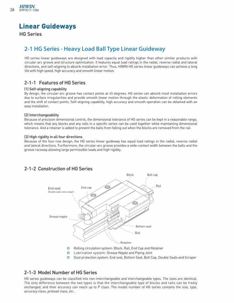
Linear Guideways HG Series Rolling circulation system: Block, Rail, End Cap and Retainer Lubrication system: Grease Nipple and Piping Joint Dust protection system: End seal, Bottom Seal, Bolt Cap, Double Seals and Scraper 2-1 HG Series - Heavy Load Ball Type Linear Guideway 2-1-3 Model Number of HG Series HG series guideways can be classified into non-interchangeable and interchangeable types. The sizes are identical. The only difference between the two types is that the interchangeable type of blocks and rails can be freely exchanged, and their accuracy can reach up to P class. The model number of HG series contains the size, type, accuracy class, preload class, etc.. 2-1-1 Features of HG Series (1) Self-aligning capability By design, the circular-arc groove has contact points at 45 degrees. HG series can absorb most installation errors due to surface irregularities and provide smooth linear motion through the elastic deformation of rolling elements and the shift of contact points. Self-aligning capability, high accuracy and smooth operation can be obtained with an easy installation. (2) Interchangeability Because of precision dimensional control, the dimensional tolerance of HG series can be kept in a reasonable range, which means that any blocks and any rails in a specific series can be used together while maintaining dimensional tolerance. And a retainer is added to prevent the balls from falling out when the blocks are removed from the rail. (3) High rigidity in all four directions Because of the four-row design, the HG series linear guideway has equal load ratings in the radial, reverse radial and lateral directions. Furthermore, the circular-arc groove provides a wide-contact width between the balls and the groove raceway allowing large permissible loads and high rigidity. Block End seal (Double seals and scraper) Grease nipple End cap Rail Bolt cap Retainer Bottom seal Ball HG series linear guideways are designed with load capacity and rigidity higher than other similar products with circular-arc groove and structure optimization. It features equal load ratings in the radial, reverse radial and lateral directions, and self-aligning to absorb installation-error. Thus, HIWIN HG series linear guideways can achieve a long life with high speed, high accuracy and smooth linear motion. 2-1-2 Construction of HG Series G99TE17-1306
-
Upload
metin-sinan-celiker -
Category
Documents
-
view
32 -
download
8
description
hiwin hg katalog
Transcript of HG Series Catalog
Linear GuidewaysHG Series
Rolling circulation system: Block, Rail, End Cap and Retainer
Lubrication system: Grease Nipple and Piping Joint
Dust protection system: End seal, Bottom Seal, Bolt Cap, Double Seals and Scraper
2-1 HG Series - Heavy Load Ball Type Linear Guideway
2-1-3 Model Number of HG SeriesHG series guideways can be classified into non-interchangeable and interchangeable types. The sizes are identical. The only difference between the two types is that the interchangeable type of blocks and rails can be freely exchanged, and their accuracy can reach up to P class. The model number of HG series contains the size, type, accuracy class, preload class, etc..
2-1-1 Features of HG Series (1) Self-aligning capability By design, the circular-arc groove has contact points at 45 degrees. HG series can absorb most installation errors due to surface irregularities and provide smooth linear motion through the elastic deformation of rolling elements and the shift of contact points. Self-aligning capability, high accuracy and smooth operation can be obtained with an easy installation.
(2) Interchangeability Because of precision dimensional control, the dimensional tolerance of HG series can be kept in a reasonable range, which means that any blocks and any rails in a specific series can be used together while maintaining dimensional tolerance. And a retainer is added to prevent the balls from falling out when the blocks are removed from the rail.
(3) High rigidity in all four directions Because of the four-row design, the HG series linear guideway has equal load ratings in the radial, reverse radial and lateral directions. Furthermore, the circular-arc groove provides a wide-contact width between the balls and the groove raceway allowing large permissible loads and high rigidity.
Block
End seal(Double seals and scraper)
Grease nipple
End capRail
Bolt cap
Retainer
Bottom seal
Ball
HG series linear guideways are designed with load capacity and rigidity higher than other similar products with circular-arc groove and structure optimization. It features equal load ratings in the radial, reverse radial and lateral directions, and self-aligning to absorb installation-error. Thus, HIWIN HG series linear guideways can achieve a long life with high speed, high accuracy and smooth linear motion.
2-1-2 Construction of HG Series
G99TE17-1306� �

Dust Protection2
E2: Self-Lubricant
SE: Metallic End Cap
Dust Protection2
E2: Self-LubricantSE: Metallic End Cap
RC:Reinforced Cap
(1) Non-interchangeable type
(2) Interchangeable typeModel Number of HG Block
Model Number of HG Rail
Note: 1. The roman numerals express a matched set of rails.
2. No symbol indicates standard protection (end seal and bottom seal).ZZ : End seal, bottom seal and scraperKK: Double seals, bottom seal and scraper.DD: Double seals and bottom seal
3. Block type HGL is the low profile design of HGH (square type), the assembled height is same as HGW (flange type) in same size.
Block TypeW : Flange Type H : Square TypeL : Square Type (Low)3
Block TypeW : Flange Type H : Square TypeL : Square Type3
HG Series
Block Mounting Type
A : Mounting From Top
B : Bottom, C : Top or Bottom
E: Special Block
None: Standard Block
Precision Code : C, H, P
Preload Code : Z0, ZA
HG Series
Rail Mounting Type
R : Mounting From Top
T : Bottom
Rail Length (mm)
E: Special Rail,
None: Standard Rail
RC:Reinforced Cap
Precision Code : C, H, PInterchangeable Rail
HG Series
Model size
15, 20, 25, 30, 35, 45, 55, 65
No. of Blocks per Rail
Rail Length (mm)
E: Special RailNone: Standard Rail
Rail Mounting TypeR : Mounting From TopT : Bottom
Preload Code: Z0, ZA, ZB
Precision Code: C, H, P, SP, UP
No.of rails per axis set 1
Load Type
C : Heavy Load
H : Super Heavy Load
Block MountingA : Mounting From TopB : BottomC : Top or Bottom
Model size
15, 20, 25, 30, 35, 45, 55, 65
Load Type
C : Heavy Load
H : Super Heavy Load
Model size
15, 20, 25, 30, 35, 45, 55, 65
E: Special Block
None: Standard Block
HG W 25 C A E 2 R 1600 E ZA P II + DD/E2/RC
HG W 25 C A E ZA P + ZZ/E2
HG R 25 R 1200 E P + RC
G99TE17-1306� �

Linear GuidewaysHG Series
Table 2-1-1 Block Types
2-1-4 Types(1) Block typesHIWIN offers two types of linear guideway which are flange and square types. Because of the low assembly height and larger mounting surface, the flange type is suitable for heavy moment load application.
Type Model Shape HeightRail
LengthMain Application
(mm) (mm)
HGH-CA HGH-HA
28
90
100
4000
Machine Centers
NC Lathes
Grinding Machines
Precision Machining Machines
Heavy Cutting Machines
Automation Devices
Transportation Equipment
Measuring Equipment
Devices Requiring High
Positional Accuracy
HGL-CA HGL-HA
24
70
100
4000
HGW-CA HGW-HA
24
90
100
4000
HGW-CB HGW-HB
24
90
100
4000
HGW-CC HGW-HC
24
90
100
4000
Sq
ua
re
Fla
ng
e
G99TE17-1306� �

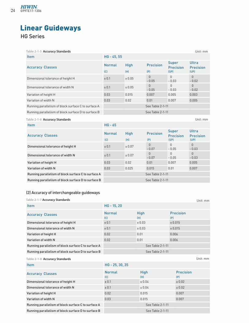
2-1-5 Accuracy ClassesThe accuracy of HG series can be classified into normal (C), high (H), precision (P), super precision (SP), ultra precision (UP), five classes. Please choose the class by referring the accuracy of applied equipment.
Table 2-1-3 Accuracy Standards Unit: mm
(1) Accuracy of non-interchangeable guideways
Item HG - 25, 30, 35
Accuracy ClassesNormal High Precision
Super Precision
Ultra Precision
(C) (H) (P) (SP) (UP)
Dimensional tolerance of height H ± 0.1 ± 0.04 0- 0.04
0- 0.02
0- 0.01
Dimensional tolerance of width N ± 0.1 ± 0.04 0- 0.04
0- 0.02
0- 0.01
Variation of height H 0.02 0.015 0.007 0.005 0.003
Variation of width N 0.03 0.015 0.007 0.005 0.003
Running parallelism of block surface C to surface A See Table 2-1-11
Running parallelism of block surface D to surface B See Table 2-1-11
Item HG - 15, 20
Accuracy ClassesNormal High Precision
Super Precision
Ultra Precision
(C) (H) (P) (SP) (UP)
Dimensional tolerance of height H ± 0.1 ± 0.03 0
- 0.03 0 - 0.015
0 - 0.008
Dimensional tolerance of width N ± 0.1 ± 0.03 0 - 0.03
0 - 0.015
0 - 0.008
Variation of height H 0.02 0.01 0.006 0.004 0.003
Variation of width N 0.02 0.01 0.006 0.004 0.003
Running parallelism of block surface C to surface A See Table 2-1-11
Running parallelism of block surface D to surface B See Table 2-1-11
Table 2-1-4 Accuracy Standards Unit: mm
Table 2-1-2 Rail Types
Mounting from Top Mounting from bottom
(2) Rail typesBesides the standard top mounting type, HIWIN also offers the bottom mounting type of rails to customers.
G99TE17-1306� �
Linear GuidewaysHG Series
Table 2-1-7 Accuracy Standards
(2) Accuracy of interchangeable guideways
Item HG - 65
Accuracy ClassesNormal High Precision
Super
Precision
Ultra
Precision (C) (H) (P) (SP) (UP)
Dimensional tolerance of height H ± 0.1 ± 0.07 0- 0.07
0- 0.05
0- 0.03
Dimensional tolerance of width N ± 0.1 ± 0.07 0- 0.07
0- 0.05
0- 0.03
Variation of height H 0.03 0.02 0.01 0.007 0.005
Variation of width N 0.03 0.025 0.015 0.01 0.007
Running parallelism of block surface C to surface A See Table 2-1-11
Running parallelism of block surface D to surface B See Table 2-1-11
Item HG - 45, 55
Accuracy ClassesNormal High Precision
Super
Precision
Ultra
Precision (C) (H) (P) (SP) (UP)
Dimensional tolerance of height H ± 0.1 ± 0.05 0- 0.05
0- 0.03
0- 0.02
Dimensional tolerance of width N ± 0.1 ± 0.05 0- 0.05
0- 0.03
0- 0.02
Variation of height H 0.03 0.015 0.007 0.005 0.003
Variation of width N 0.03 0.02 0.01 0.007 0.005
Running parallelism of block surface C to surface A See Table 2-1-11
Running parallelism of block surface D to surface B See Table 2-1-11
Unit: mm
Item HG - 15, 20
Accuracy Classes Normal High Precision(C) (H) (P)
Dimensional tolerance of height H ± 0.1 ± 0.03 ± 0.015
Dimensional tolerance of width N ± 0.1 ± 0.03 ± 0.015
Variation of height H 0.02 0.01 0.006
Variation of width N 0.02 0.01 0.006
Running parallelism of block surface C to surface A See Table 2-1-11
Running parallelism of block surface D to surface B See Table 2-1-11
Item HG - 25, 30, 35
Accuracy Classes Normal High Precision(C) (H) (P)
Dimensional tolerance of height H ± 0.1 ± 0.04 ± 0.02
Dimensional tolerance of width N ± 0.1 ± 0.04 ± 0.02
Variation of height H 0.02 0.015 0.007
Variation of width N 0.03 0.015 0.007
Running parallelism of block surface C to surface A See Table 2-1-11
Running parallelism of block surface D to surface B See Table 2-1-11
Table 2-1-5 Accuracy Standards Unit: mm
Table 2-1-6 Accuracy Standards Unit: mm
Table 2-1-8 Accuracy Standards Unit: mm
G99TE17-1306� �

(3) Accuracy of running parallelism
Rail Length (mm) Accuracy (µm)
C H P SP UP
~ 100 12 7 3 2 2
100 ~ 200 14 9 4 2 2
200 ~ 300 15 10 5 3 2
300 ~ 500 17 12 6 3 2
500 ~ 700 20 13 7 4 2
700 ~ 900 22 15 8 5 3
900 ~ 1,100 24 16 9 6 3
1,100 ~ 1,500 26 18 11 7 4
1,500 ~ 1,900 28 20 13 8 4
1,900 ~ 2,500 31 22 15 10 5
2,500 ~ 3,100 33 25 18 11 6
3,100 ~ 3,600 36 27 20 14 7
3,600 ~ 4,000 37 28 21 15 7
Item HG - 45, 55
Accuracy Classes Normal High Precision(C) (H) (P)
Dimensional tolerance of height H ± 0.1 ± 0.05 ± 0.025
Dimensional tolerance of width N ± 0.1 ± 0.05 ± 0.025
Variation of height H 0.03 0.015 0.007
Variation of width N 0.03 0.02 0.01
Running parallelism of block surface C to surface A See Table 2-1-11
Running parallelism of block surface D to surface B See Table 2-1-11
Table 2-1-9 Accuracy Standards Unit: mm
Item HG - 65
Accuracy Classes Normal High Precision(C) (H) (P)
Dimensional tolerance of height H ± 0.1 ± 0.07 ± 0.035
Dimensional tolerance of width N ± 0.1 ± 0.07 ± 0.035
Variation of height H 0.03 0.02 0.01
Variation of width N 0.03 0.025 0.015
Running parallelism of block surface C to surface A See Table 2-1-11
Running parallelism of block surface D to surface B See Table 2-1-11
Table 2-1-10 Accuracy Standards Unit: mm
Table 2-1-11 Accuracy of Running Parallelism
G99TE17-1306� �
Linear GuidewaysHG Series
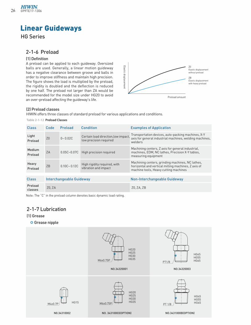
(2) Preload classesHIWIN offers three classes of standard preload for various applications and conditions.
2-1-6 Preload(1) Definition A preload can be applied to each guideway. Oversized balls are used. Generally, a linear motion guideway has a negative clearance between groove and balls in order to improve stiffness and maintain high precision. The figure shows the load is multiplied by the preload, the rigidity is doubled and the deflection is reduced by one half. The preload not larger than ZA would be recommended for the model size under HG20 to avoid an over-preload affecting the guideway’s life.
Elastic d
isplacem
ent
Preload amount
Z0Elastic displacementwithout preload
ZBElastic displacementwith heavy preload
Class Code Preload Condition Examples of Application
Light
PreloadZ0 0~ 0.02C
Certain load direction,low impact, low precision required
Transportation devices, auto-packing machines, X-Y axis for general industrial machines, welding machines, welders
Medium
PreloadZA 0.05C~0.07C High precision required
Machining centers, Z axis for general industrial, machines, EDM, NC lathes, Precision X-Y tables, measuring equipment
Heavy
PreloadZB 0.10C~ 0.12C
High rigidity required, with vibration and impact
Machining centers, grinding machines, NC lathes, horizontal and vertical milling machines, Z axis of machine tools, Heavy cutting machines
Table 2-1-12 Preload Classes
Class Interchangeable Guideway Non-Interchangeable Guideway
Preload classes
Z0, ZA Z0, ZA, ZB
Note: The “C” in the preload column denotes basic dynamic load rating.
2-1-7 Lubrication(1) Grease
Grease nipple
HG15
HG20HG25HG30HG35
NO.34320001
NO. 34310003(OPTION)
M6x0.75P
M6x0.75PM4x0.7P
HG20HG25HG30HG35
N0.34310002
HG45HG55HG65
NO.34320003
NO.3431000B(OPTION)
PT1/8
PT 1/8
HG45HG55HG65
G99TE17-1306� �

Size Heavy load Super heavy load
SizeHeavy load Super heavy load
(cm3) (cm3) (cm3) (cm3)
HG15 1 - HG35 10 12
HG20 2 3 HG45 17 21
HG25 5 6 HG55 26 33
HG30 7 8 HG65 50 61
The standard location of the grease fitting is at both ends of the block, but the nipple can be mounted at each side of block. For lateral installation, we recommend that the nipple be mounted at the non-reference side, otherwise please contact us. It is possible to perform lubrication by using the oil-piping joint.
The lubricant amount for a block filled with grease
Mounting location
Frequency of replenishmentCheck the grease every 100 km, or every 3-6 months.
Size O-Ring
Lube hole at top: max. permissible depth for piercing
do (mm) W (mm) Tmax (mm)
HG15 2.5±0.15 1.5±0.15 3.75
HG20 4.5±0.15 1.5±0.15 5.7
HG25 4.5±0.15 1.5±0.15 5.8
HG30 4.5±0.15 1.5±0.15 6.3
HG35 4.5±0.15 1.5±0.15 8.8
HG45 4.5±0.15 1.5±0.15 8.2
HG55 4.5±0.15 1.5±0.15 11.8
HG65 4.5±0.15 1.5±0.15 10.8
dia.0.8
Tmax
Table 2-1-13 O-Ring size and max. permissible depth for piercing
do
W
O Ring
Table 2-1-14 The lubricant Amount for a Block Filled with Grease
G99TE17-1306� �

Linear GuidewaysHG Series
(2) OilThe recommended viscosity of oil is about 30~150cSt. If customers need to use oil-type lubrication, please inform us.
Types of oil piping joint
Ø5.5
7.4
2.5
8
15
M6x0.75P
M4x0.7P
PT 1/8
M8x1.0P
10
20
2
Ø10
19
.5
M8x1.0P 18
10
M6x0.75P
3
Ø8
PT 1/8
M6x0.75PØ8
PT 1/8
PT 1/8
12
25
5
Ø11
PT 1/8
PT 1/8
12
25
Ø10
5
11 12
10
12
NO.970003A1
NO.970005A1
NO.970002A1
NO.970004A1
NO.970006A1
NO.970007A1
NO.970008A1
12
23
.5
5
SF-86
SF-78
SF-88
LF-76
LF-86
LF-78
LF-88
11
10
12
M6x0.75P
M8x1.0P
10
19
.5
3
Ø8
10
NO.970001A1
SF-76
HG15
NO.97000EA1
LF-64
HG20HG25HG30HG35
HG20HG25HG30HG35
HG45HG55HG65
HG20HG25HG30HG35
HG20HG25HG30HG35
HG45HG55HG65
HG45HG55HG65
HG45HG55HG65
PT 1/8
12
23
.5
M6x0.75P Ø8
5
11
8
16
.5
M6x0.75P
M4x0.7P
4
Ø5
10
7
HG15
NO.97001TA1
SF-64
M8x1.0P
PT 1/8
18
10
20
2
Ø10
10
G99TE17-1306� �
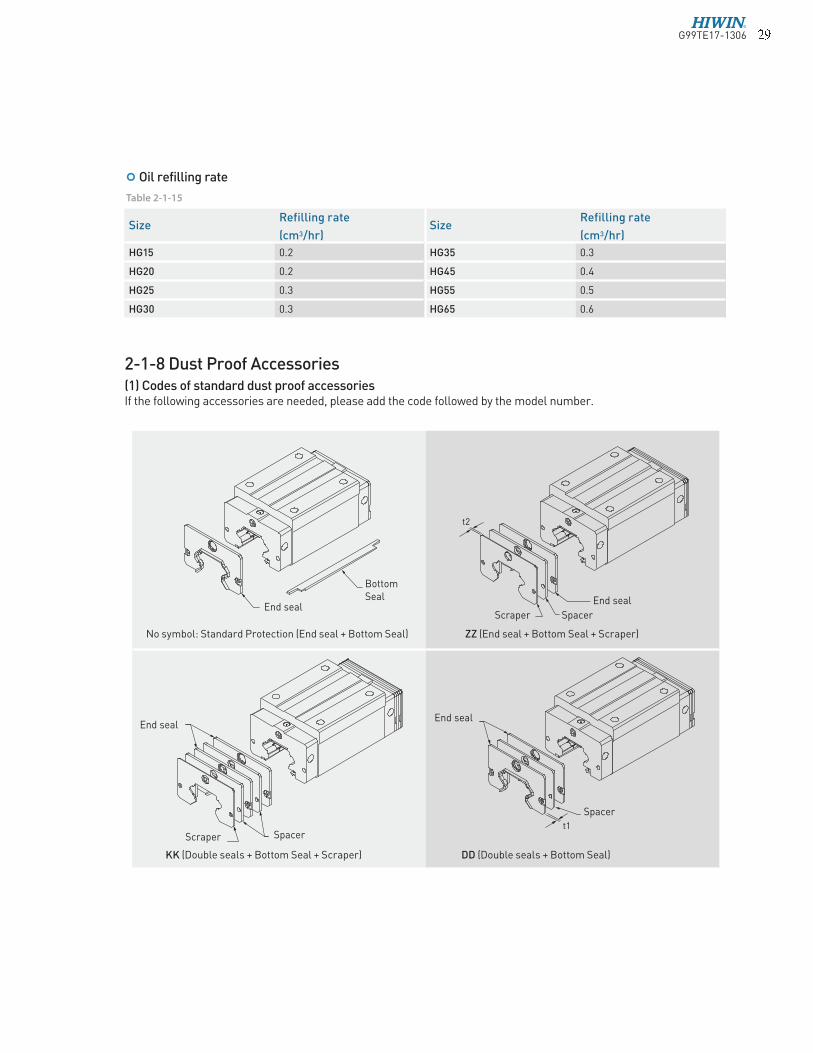
2-1-8 Dust Proof Accessories(1) Codes of standard dust proof accessoriesIf the following accessories are needed, please add the code followed by the model number.
t2
t1
Scraper
End seal
Spacer
End seal
Spacer
Bottom Seal End seal
End seal
Scraper
No symbol: Standard Protection (End seal + Bottom Seal)
KK (Double seals + Bottom Seal + Scraper) DD (Double seals + Bottom Seal)
ZZ (End seal + Bottom Seal + Scraper)
Spacer
Size Refilling rate
SizeRefilling rate
(cm3/hr) (cm3/hr)
HG15 0.2 HG35 0.3
HG20 0.2 HG45 0.4
HG25 0.3 HG55 0.5
HG30 0.3 HG65 0.6
Oil refilling rate
Table 2-1-15
G99TE17-1306�

Linear GuidewaysHG Series
(2) Codes of high-dust proof accessoriesHIWIN develops many kinds of dust proof accessories for different application and working environment to avoid dust or debris. If the following accessories are needed, please add the code followed by the model number.
KH {Double End Seal (High Dust Proof) + Bottom Seal (High Dust Proof) +Top Seal +Scraper}
Note: 1. The available size for high dust proof accessories are HG20(C/H), 25(C/H), 30(C/H), 35(C/H) and 45C. 2. The value of fricton force will increase 0.6~1.2 kgf.
t2
t1
End seal End seal
Scraper
Scraper
End seal End seal
Top Seal Top Seal
Top Seal Top Seal
Spacer
Spacer
Spacer
SH {End Seal (High-Dust Proof) + Bottom Seal (High Dust Proof) + Top Seal}
ZH {End Seal (High-Dust Proof) +Bottom Seal (High Dust Proof) + Top Seal + Spacer}
DH {Double End Seal (High Dust Proof) +Bottom Seal (High Dust Proof) + Top Seal}
Bottom Seal
G99TE17-1306� �

Size Thickness (t2) Size Thickness (t2)
(mm) (mm)
HG15 SC 1.5 HG35 SC 1.5
HG20 SC 1.5 HG45 SC 1.5
HG25 SC 1.5 HG55 SC 1.5
HG30 SC 1.5 HG65 SC 1.5
(4) Fuction of dust proof accessories
End seal and bottom seal To prevent life reduction caused by iron chips or dust entering the block.
Double sealsEnhances the wiping effect, foreign matter can be completely wiped off.
Size Thickness (t1) Size Thickness (t1)
(mm) (mm)
HG15 ES 3 HG35 ES 3.2
HG20 ES 3.5 HG45 ES 4.5
HG25 ES 3.5 HG55 ES 4.5
HG30 ES 3.2 HG65 ES 6
Table 2-1-17 Dimensions of scraper
ScraperThe scraper removes high-temperature iron chips and larger foreign objects.
Table 2-1-16 Dimensions of end seal
Top SealTop seal can efficiently avoid dust from the surface of rail or tapping hole getting inside the block.
SW (End Seal(Ultra-high dustproof) +Bottom Seal(Ultra-high dustproof) +Top Seal)
(3) Codes of ultra-high dust proof accessoriesHiwin has developed high dust proof accessories which is used for environment that is full of dust and particle, such as wood working machinery and glass/stone machining equipment. These accessories show high performance of dust proof. If accessories are needed, please add the code followed by the model number.
Note : 1. The available size for high dust proof accessories are HG15C, HG20(C/H), HG30(C/H), HG35(C/H), HG45(C/H). 2. The value of fricton force will increase 1.5~4.0 kgf.
ZW (End Seal(Ultra-high dustproof) +Bottom Seal(Ultra-high dustproof) +Top Seal+Scraper)
End seal End seal
Spacer
Scraper
Bottom Seal Bottom Seal
Top Seal Top Seal
G99TE17-1306 �

Linear GuidewaysHG Series
Rail size Bolt size Diameter(D) Thickness(H) Rail size Bolt size Diameter(D) Thickness(H)
(mm) (mm) (mm) (mm)
HGR15 M4 7.65 1.1 HGR35 M8 14.25 3.3
HGR20 M5 9.65 2.2 HGR45 M12 20.25 4.6
HGR25 M6 11.20 2.5 HGR55 M14 23.50 5.5
HGR30 M8 14.25 3.3 HGR65 M16 26.60 5.5
Table 2-1-18 Dimensions of Bolt Caps for Rail Mounting Holes
Bolt caps for rail mounting holesCaps are used to cover the mounting holes to prevent chips or other foreign objects from collecting in the holes. The caps will be enclosed in each rail package.
SizeOverall block length (L)
Standard/SH ZZ/ZH DD/DH KK/KH SW ZW
*HG15C 61.4 69 68 75.6 63.2 71
*HG20C 77.5 82.5 82.5 87.5 78.5 86.3
*HG20H 92.2 97.2 97.5 102.2 93.2 101
*HG25C 84 89 89 94 85 92.8
*HG25H 104.6 109.6 109.6 114.6 105.6 113.4
*HG30C 97.4 105.4 104.8 112.8 99 107.2
*HG30H 120.4 128.4 127.8 135.8 122 99.6
*HG35C 112.4 120.4 119.8 127.8 115.2 123.4
*HG35H 138.2 146.2 145.6 153.6 141 149.2
*HG45C 139.4 150 149.4 160 140 148.8
*HG45H 171.2 181.8 181.2 191.8 171.8 180.6
*HG55C 166.7 177.1 177.1 187.5 - -
*HG55H 204.8 215.2 215.2 225.5 - -
*HG65C 200.2 208.2 209.2 217.2 - -
*HG65H 259.6 267.6 268.6 276.6 - -
unit: mm
(5) Dimensions of block equipped with the dustproof parts
Note : For the marking of “*”, it means this specification is available for SH/ZH/DH/KH dust proof accessories.
Table 2-1-19 Overall block length
L
G99TE17-1306 �

2-1-10 The Accuracy Tolerance of Mounting Surface
(1) The accuracy tolerance of rail-mounting surfaceBecause of the Circular-arc contact design, the HG linear guideway can compensate for some surface-error on installation and still maintain smooth linear motion.As long as the accuracy requirements for the mounting surface are followed, high accuracy and rigidity of linear motion of the guideway can be obtained without any difficulty. In order to satisfy the needs of fast installation and smooth movement, HIWIN offers the normal clearance type of preload to customers of its high absorption ability of the deviation in mounting surface accuracy.
SizePreload classes
Z0 ZA ZB
HG15 25 18 -
HG20 25 20 18
HG25 30 22 20
HG30 40 30 27
HG35 50 35 30
HG45 60 40 35
HG55 70 50 45
HG65 80 60 55
Table 2-1-21 Max. Parallelism Tolerance (P) unit: µm
Size Resistance N (kgf) Size Resistance N (kgf)
HG15 1.18 (0.12) HG35 3.04 (0.31)
HG20 1.57 (0.16) HG45 3.83 (0.39)
HG25 1.96 (0.2) HG55 4.61 (0.47)
HG30 2.65 (0.27) HG65 5.79 (0.59)
Note:1kgf=9.81N
2-1-9 FrictionThe maximum value of resistance per end seal are as shown in the table.
Table 2-1-20 Seal Resistance
(2) The parallelism tolerance of reference surface (P)
(3) The accuracy tolerance of reference surface height
SizePreload classes
Z0 ZA ZB
HG15 130 85 -
HG20 130 85 50
HG25 130 85 70
HG30 170 110 90
HG35 210 150 120
HG45 250 170 140
HG55 300 210 170
HG65 350 250 200
Table 2-1-22 Max. Tolerance of Reference Surface Height (S1) unit: µm
G99TE17-1306

Linear GuidewaysHG Series
Size Bolt sizeTorque N-cm (kgf-cm)
Iron Casting Aluminum
HG15 M4×0.7P×16L 392 (40) 274 (28) 206 (21)
HG20 M5×0.8P×16L 883 (90) 588 (60) 441 (45)
HG25 M6×1P×20L 1373 (140) 921 (94) 686 (70)
HG30 M8×1.25P×25L 3041 (310) 2010 (205) 1470 (150)
HG35 M8×1.25P×25L 3041 (310) 2010 (205) 1470 (150)
HG45 M12×1.75P×35L 11772 (1200) 7840 (800) 5880 (600)
HG55 M14×2P×45L 15696 (1600) 10500 (1100) 7840 (800)
HG65 M16×2P×50L 19620 (2000) 13100 (1350) 9800 (1000)
2-1-11 Cautions for Installation(1) Shoulder heights and filletsImproper shoulder heights and fillets of mounting surfaces will cause a deviation in accuracy and the interference with the chamfered part of the rail or block. As long as the recommended shoulder heights and fillets are followed, installation inaccuracies should be eliminated.
SizeMax. radius of fillets
Max. radius of fillets
Shoulder height of the rail
Shoulder height of the block
Clearance under block
r1 (mm) r2 (mm) E1 (mm) E2 (mm) H1 (mm)
HG15 0.5 0.5 3 4 4.3
HG20 0.5 0.5 3.5 5 4.6
HG25 1.0 1 5 5 5.5
HG30 1.0 1 5 5 6
HG35 1.0 1 6 6 7.5
HG45 1.0 1 8 8 9.5
HG55 1.5 1.5 10 10 13
HG65 1.5 1.5 10 10 15
Table 2-1-23 Shoulder Heights and Fillets
Table 2-1-24 Mounting Torque
(2) Tightening Torque of Bolts for InstallationImproper tightening of bolts will seriously influence the accuracy of Linear Guideway installation. The following tightening torques for different sizes of bolts are recommended.
r2
E2
r1
E1H1
BlockRail
Block
G99TE17-1306

Item HG15 HG20 HG25 HG30 HG35 HG45 HG55 HG65
Standard Length L(n)
160 (3) 220 (4) 220 (4) 280 (4) 280 (4) 570 (6) 780 (7) 1,270 (9)
220 (4) 280 (5) 280 (5) 440 (6) 440 (6) 885 (9) 1,020 (9) 1,570 (11)
280 (5) 340 (6) 340 (6) 600 (8) 600 (8) 1,200 (12) 1,260 (11) 2,020 (14)
340 (6) 460 (8) 460 (8) 760 (10) 760 (10) 1,620 (16) 1,500 (13) 2,620 (18)
460 (8) 640 (11) 640 (11) 1,000 (13) 1,000 (13) 2,040 (20) 1,980 (17)
640 (11) 820 (14) 820 (14) 1,640 (21) 1,640 (21) 2,460 (24) 2,580 (22)
820 (14) 1,000 (17) 1,000 (17) 2,040 (26) 2,040 (26) 2,985 (29) 2,940 (25)
1,240 (21) 1,240 (21) 2,520 (32) 2,520 (32)
1,600 (27) 3,000 (38) 3,000 (38)
Pitch (P) 60 60 60 80 80 105 120 150
Distance to End (Es) 20 20 20 20 20 22.5 30 35
Max. Standard Length 1,960 (33) 4,000 (67) 4,000 (67) 3,960 (50) 3,960 (50) 3,930 (38) 3,900 (33) 3,970 (27)
Max. Length 2,000 4,000 4,000 4,000 4,000 4,000 4,000 4,000
n=(Number of rail mounting holes)
Table 2-1-25 Rail Standard Length and Max. Length
L : Total length of rail (mm)n : Number of mounting holesP : Distance between any two holes (mm)E : Distance from the center of the last hole to the edge (mm)
2-1-12 Standard and Maximum Lengths of Rail
Eq.2.1=(n-1) L P + 2x x E
HIWIN offers standard rail lengths for customer needs. For non-standard E-values, the recommended dimension should not be greater than 1/2 of the pitch (P) dimension. This will prevent an unstable rail end.
unit: mm
Note : 1. Tolerance of E value for standard rail is 0.5~-0.5 mm. Tolerance of E value for jointed rail is 0~-0.3 mm. 2. Maximum standard length means the max. rail length with standard E value on both sides.
3. If different E value is needed, please contact HIWIN.
G99TE17-1306 �

Linear GuidewaysHG Series
P
N
H
h
E
Ød
W
B
T
4-Mxl
ØD
G L
E
C
K1
L1K2
H3
H2
HR
H1
B1
WR
(1) HGH-CA / HGH-HA
Note : 1 kgf = 9.81 N
2-1-13 Dimensions for HIWIN HG Series
Model No.
Dimensions
of Assembly
(mm)
Dimensions of Block (mm) Dimensions of Rail (mm)
Mounting
Bolt for
Rail
Basic
Dynamic
Load
Rating
Basic
Static
Load
Rating
Static Rated
MomentWeight
MR
kN-m
MP
kN-m
MY
kN-m
Block
kg
Rail
kg/mH H1 N W B B1 C L1 L K1 K2 G Mxl T H2 H3 WR HR D h d P E (mm) C(kN) C0 (kN)
HGH15CA 28 4.3 9.5 34 26 4 26 39.4 61.4 10 4.85 5.3 M4x5 6 7.95 7.7 15 15 7.5 5.3 4.5 60 20 M4x16 11.38 16.97 0.12 0.10 0.10 0.18 1.45
HGH20CA
30 4.6 12 44 32 6
36 50.5 77.5 12.25
6 12 M5x6 8 6 6 20 17.5 9.5 8.5 6 60 20 M5x16
17.75 27.76 0.27 0.20 0.20 0.30
2.21
HGH20HA 50 65.2 92.2 12.6 21.18 35.90 0.35 0.35 0.35 0.39
HGH25CA
40 5.5 12.5 48 35 6.5
35 58 84 15.7
6 12 M6x8 8 10 9 23 22 11 9 7 60 20 M6x20
26.48 36.49 0.42 0.33 0.33 0.51
3.21
HGH25HA 50 78.6 104.6 18.5 32.75 49.44 0.56 0.57 0.57 0.69
HGH30CA
45 6 16 60 40 10
40 70 97.4 20.25
6 12 M8x10 8.5 9.5 13.8 28 26 14 12 9 80 20 M8x25
38.74 52.19 0.66 0.53 0.53 0.88
4.47
HGH30HA 60 93 120.4 21.75 47.27 69.16 0.88 0.92 0.92 1.16
HGH35CA
55 7.5 18 70 50 10
50 80 112.4 20.6
7 12 M8x12 10.2 16 19.6 34 29 14 12 9 80 20 M8x25
49.52 69.16 1.16 0.81 0.81 1.45
6.30
HGH35HA 72 105.8 138.2 22.5 60.21 91.63 1.54 1.40 1.40 1.92
HGH45CA
70 9.5 20.5 86 60 13
60 97 139.4 23
10 12.9 M10x17 16 18.5 30.5 45 38 20 17 14 105 22.5 M12x35
77.57 102.71 1.98 1.55 1.55 2.73
10.41
HGH45HA 80 128.8 171.2 28.9 94.54 136.46 2.63 2.68 2.68 3.61
HGH55CA
80 13 23.5 100 75 12.5
75 117.7 166.7 27.35
11 12.9 M12x18 17.5 22 29 53 44 23 20 16 120 30 M14x45
114.44 148.33 3.69 2.64 2.64 4.17
15.08
HGH55HA 95 155.8 204.8 36.4 139.35 196.20 4.88 4.57 4.57 5.49
HGH65CA
90 15 31.5 126 76 25
70 144.2 200.2 43.1
14 12.9 M16x20 25 15 15 63 53 26 22 18 150 35 M16x50
163.63 215.33 6.65 4.27 4.27 7.00
21.18
HGH65HA 120 203.6 259.6 47.8 208.36 303.13 9.38 7.38 7.38 9.82
G99TE17-1306 �

P
H
T H
B
W
W
H
N
1
H
RØd
E
R
2
h
ØD
B4-Mxl
1
G L
H
E
3
L
C
1
K1
K2
Note : 1 kgf = 9.81 N
(2) HGL-CA / HGL-HA
Model No.
Dimensions
of Assembly
(mm)
Dimensions of Block (mm) Dimensions of Rail (mm)
Mounting
Bolt for
Rail
Basic
Dynamic
Load
Rating
Basic
Static
Load
Rating
Static Rated
MomentWeight
MR
kN-m
MP
kN-m
MY
kN-m
Block
kg
Rail
kg/mH H1 N W B B1 C L1 L K1 K2 G Mxl T H2 H3 WR HR D h d P E (mm) C(kN) C0 (kN)
HGL15CA 24 4.3 9.5 34 26 4 26 39.4 61.4 10 4.85 5.3 M4x4 6 3.95 3.7 15 15 7.5 5.3 4.5 60 20 M4x16 11.38 16.97 0.12 0.10 0.10 0.14 1.45
HGL25CA
36 5.5 12.5 48 35 6.5
35 58 84 15.7
6 12 M6x6 8 6 5 23 22 11 9 7 60 20 M6x20
26.48 36.49 0.42 0.33 0.33 0.42
3.21
HGL25HA 50 78.6 104.6 18.5 32.75 49.44 0.56 0.57 0.57 0.57
HGL30CA
42 6 16 60 40 10
40 70 97.4 20.25
6 12 M8x10 8.5 6.5 10.8 28 26 14 12 9 80 20 M8x25
38.74 52.19 0.66 0.53 0.53 0.78
4.47
HGL30HA 60 93 120.4 21.75 47.27 69.16 0.88 0.92 0.92 1.03
HGL35CA
48 7.5 18 70 50 10
50 80 112.4 20.6
7 12 M8x12 10.2 9 12.6 34 29 14 12 9 80 20 M8x25
49.52 69.16 1.16 0.81 0.81 1.14
6.30
HGL35HA 72 105.8 138.2 22.5 60.21 91.63 1.54 1.40 1.40 1.52
HGL45CA
60 9.5 20.5 86 60 13
60 97 139.4 23
10 12.9 M10x17 16 8.5 20.5 45 38 20 17 14 105 22.5 M12x35
77.57 102.71 1.98 1.55 1.55 2.08
10.41
HGL45HA 80 128.8 171.2 28.9 94.54 136.46 2.63 2.68 2.68 2.75
HGL55CA
70 13 23.5 100 75 12.5
75 117.7 166.7 27.35
11 12.9 M12x18 17.5 12 19 53 44 23 20 16 120 30 M14x45
114.44 148.33 3.69 2.64 2.64 3.25
15.08
HGL55HA 95 155.8 204.8 36.4 139.35 196.20 4.88 4.57 4.57 4.27
G99TE17-1306 �

Linear GuidewaysHG Series
Ød
P
W
B
EN
H
T
h
ØD
4-MC
G L
EWR
K1
L1
H2
HR
H1
T1
B1
H3
K2
(3) HGW-CA / HGW-HA
Note : 1 kgf = 9.81 N
Model No.
Dimensions
of Assembly
(mm)
Dimensions of Block (mm) Dimensions of Rail (mm)
Mounting
Bolt for
Rail
Basic
Dynamic
Load
Rating
Basic
Static
Load
Rating
Static Rated
MomentWeight
MR
kN-m
MP
kN-m
MY
kN-m
Block
kg
Rail
kg/mH H1 N W B B1 C L1 L K1 K2 G M T T1 H2 H3 WR HR D h d P E (mm) C(kN) C0(kN)
HGW15CA 24 4.3 16 47 38 4.5 30 39.4 61.4 8 4.85 5.3 M5 6 8.9 3.95 3.7 15 15 7.5 5.3 4.5 60 20 M4x16 11.38 16.97 0.12 0.10 0.10 0.17 1.45
HGW20CA
30 4.6 21.5 63 53 5 40
50.5 77.5 10.25
6 12 M6 8 10 6 6 20 17.5 9.5 8.5 6 60 20 M5x16
17.75 27.76 0.27 0.20 0.20 0.40
2.21
HGW20HA 65.2 92.2 17.6 21.18 35.90 0.35 0.35 0.35 0.52
HGW25CA
36 5.5 23.5 70 57 6.5 45
58 84 10.7
6 12 M8 8 14 6 5 23 22 11 9 7 60 20 M6x20
26.48 36.49 0.42 0.33 0.33 0.59
3.21
HGW25HA 78.6 104.6 21 32.75 49.44 0.56 0.57 0.57 0.80
HGW30CA
42 6 31 90 72 9 52
70 97.4 14.25
6 12 M10 8.5 16 6.5 10.8 28 26 14 12 9 80 20 M8x25
38.74 52.19 0.66 0.53 0.53 1.09
4.47
HGW30HA 93 120.4 25.75 47.27 69.16 0.88 0.92 0.92 1.44
HGW35CA
48 7.5 33 100 82 9 62
80 112.4 14.6
7 12 M10 10.1 18 9 12.6 34 29 14 12 9 80 20 M8x25
49.52 69.16 1.16 0.81 0.81 1.56
6.30
HGW35HA 105.8 138.2 27.5 60.21 91.63 1.54 1.40 1.40 2.06
HGW45CA
60 9.5 37.5 120 100 10 80
97 139.4 13
10 12.9 M12 15.1 22 8.5 20.5 45 38 20 17 14 105 22.5 M12x35
77.57 102.71 1.98 1.55 1.55 2.79
10.41
HGW45HA 128.8 171.2 28.9 94.54 136.46 2.63 2.68 2.68 3.69
HGW55CA
70 13 43.5 140 116 12 95
117.7 166.7 17.35
11 12.9 M14 17.5 26.5 12 19 53 44 23 20 16 120 30 M14x45
114.44 148.33 3.69 2.64 2.64 4.52
15.08
HGW55HA 155.8 204.8 36.4 139.35 196.20 4.88 4.57 4.57 5.96
HGW65CA
90 15 53.5 170 142 14 110
144.2 200.2 23.1
14 12.9 M16 25 37.5 15 15 63 53 26 22 18 150 35 M16x50
163.63 215.33 6.65 4.27 4.27 9.17
21.18
HGW65HA 203.6 259.6 52.8 208.36 303.13 9.38 7.38 7.38 12.89
G99TE17-1306� �
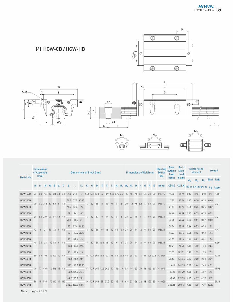
(4) HGW-CB / HGW-HB
PN
H
E
Ød
B
W
T
4-Mh
ØD
E
G L
C
K1
L1
H2
HR
H3
T2
H1
T1
B1
WR
K2
Note : 1 kgf = 9.81 N
Model No.
Dimensions
of Assembly
(mm)
Dimensions of Block (mm) Dimensions of Rail (mm)
Mounting
Bolt for
Rail
Basic
Dynamic
Load
Rating
Basic
Static
Load
Rating
Static Rated
MomentWeight
MR
kN-m
MP
kN-m
MY
kN-m
Block
kg
Rail
kg/mH H1 N W B B1 C L1 L K1 K2 G M T T1 T2 H2 H3 WR HR D h d P E (mm) C(kN) C0 (kN)
HGW15CB 24 4.3 16 47 38 4.5 30 39.4 61.4 8 4.85 5.3 Ø4.5 6 8.9 6.95 3.95 3.7 15 15 7.5 5.3 4.5 60 20 M4x16 11.38 16.97 0.12 0.10 0.10 0.17 1.45
HGW20CB
30 4.6 21.5 63 53 5 40
50.5 77.5 10.25
6 12 Ø6 8 10 9.5 6 6 20 17.5 9.5 8.5 6 60 20 M5x16
17.75 27.76 0.27 0.20 0.20 0.40
2.21
HGW20HB 65.2 92.2 17.6 21.18 35.90 0.35 0.35 0.35 0.52
HGW25CB
36 5.5 23.5 70 57 6.5 45
58 84 10.7
6 12 Ø7 8 14 10 6 5 23 22 11 9 7 60 20 M6x20
26.48 36.49 0.42 0.33 0.33 0.59
3.21
HGW25HB 78.6 104.6 21 32.75 49.44 0.56 0.57 0.57 0.80
HGW30CB
42 6 31 90 72 9 52
70 97.4 14.25
6 12 Ø9 8.5 16 10 6.5 10.8 28 26 14 12 9 80 20 M8x25
38.74 52.19 0.66 0.53 0.53 1.09
4.47
HGW30HB 93 120.4 25.75 47.27 69.16 0.88 0.92 0.92 1.44
HGW35CB
48 7.5 33 100 82 9 62
80 112.4 14.6
7 12 Ø9 10.1 18 13 9 12.6 34 29 14 12 9 80 20 M8x25
49.52 69.16 1.16 0.81 0.81 1.56
6.30
HGW35HB 105.8 138.2 27.5 60.21 91.63 1.54 1.40 1.40 2.06
HGW45CB
60 9.5 37.5 120 100 10 80
97 139.4 13
10 12.9 Ø11 15.1 22 15 8.5 20.5 45 38 20 17 14 105 22.5 M12x35
77.57 102.71 1.98 1.55 1.55 2.79
10.41
HGW45HB 128.8 171.2 28.9 94.54 136.46 2.63 2.68 2.68 3.69
HGW55CB
70 13 43.5 140 116 12 95
117.7 166.7 17.35
11 12.9 Ø14 17.5 26.5 17 12 19 53 44 23 20 16 120 30 M14x45
114.44 148.33 3.69 2.64 2.64 4.52
15.08
HGW55HB 155.8 204.8 36.4 139.35 196.20 4.88 4.57 4.57 5.96
HGW65CB
90 15 53.5 170 142 14 110
144.2 200.2 23.1
14 12.9 Ø16 25 37.5 23 15 15 63 53 26 22 18 150 35 M16x50
163.63 215.33 6.65 4.27 4.27 9.17
21.18
HGW65HB 203.6 259.6 52.8 208.36 303.13 9.38 7.38 7.38 12.89
G99TE17-1306� �

Linear GuidewaysHG Series
P
ØDT
H
N Ød
E
h
W
B4-M
G L
E
C
K1
H2
T2
T1
H1
HR
H3
B1
WR
L1K2
(5) HGW-CC / HGW-HC
Note : 1 kgf = 9.81 N
Model No.
Dimensions
of Assembly
(mm)
Dimensions of Block (mm) Dimensions of Rail (mm)
Mounting
Bolt for
Rail
Basic
Dynamic
Load
Rating
Basic
Static
Load
Rating
Static Rated
MomentWeight
MR
kN-m
MP
kN-m
MY
kN-m
Block
kg
Rail
kg/mH H1 N W B B1 C L1 L K1 K2 G M T T1 T2 H2 H3 WR HR D h d P E (mm) C(kN) C0 (kN)
HGW15CC 24 4.3 16 47 38 4.5 30 39.4 61.4 8 4.85 5.3 M5 6 8.9 6.95 3.95 3.7 15 15 7.5 5.3 4.5 60 20 M4x16 11.38 16.97 0.12 0.10 0.10 0.17 1.45
HGW20CC
30 4.6 21.5 63 53 5 40
50.5 77.5 10.25
6 12 M6 8 10 9.5 6 6 20 17.5 9.5 8.5 6 60 20 M5x16
17.75 27.76 0.27 0.20 0.20 0.40
2.21
HGW20HC 65.2 92.2 17.6 21.18 35.90 0.35 0.35 0.35 0.52
HGW25CC
36 5.5 23.5 70 57 6.5 45
58 84 10.7
6 12 M8 8 14 10 6 5 23 22 11 9 7 60 20 M6x20
26.48 36.49 0.42 0.33 0.33 0.59
3.21
HGW25HC 78.6 104.6 21 32.75 49.44 0.56 0.57 0.57 0.80
HGW30CC
42 6 31 90 72 9 52
70 97.4 14.25
6 12 M10 8.5 16 10 6.5 10.8 28 26 14 12 9 80 20 M8x25
38.74 52.19 0.66 0.53 0.53 1.09
4.47
HGW30HC 93 120.4 25.75 47.27 69.16 0.88 0.92 0.92 1.44
HGW35CC
48 7.5 33 100 82 9 62
80 112.4 14.6
7 12 M10 10.1 18 13 9 12.6 34 29 14 12 9 80 20 M8x25
49.52 69.16 1.16 0.81 0.81 1.56
6.30
HGW35HC 105.8 138.2 27.5 60.21 91.63 1.54 1.40 1.40 2.06
HGW45CC
60 9.5 37.5 120 100 10 80
97 139.4 13
10 12.9 M12 15.1 22 15 8.5 20.5 45 38 20 17 14 105 22.5 M12x35
77.57 102.71 1.98 1.55 1.55 2.79
10.41
HGW45HC 128.8 171.2 28.9 94.54 136.46 2.63 2.68 2.68 3.69
HGW55CC
70 13 43.5 140 116 12 95
117.7 166.7 17.35
11 12.9 M14 17.5 26.5 17 12 19 53 44 23 20 16 120 30 M14x45
114.44 148.33 3.69 2.64 2.64 4.52
15.08
HGW55HC 155.8 204.8 36.4 139.35 196.20 4.88 4.57 4.57 5.96
HGW65CC
90 15 53.5 170 142 14 110
144.2 200.2 23.1
14 12.9 M16 25 37.5 23 15 15 63 53 26 22 18 150 35 M16x50
163.63 215.33 6.65 4.27 4.27 9.17
21.18
HGW65HC 203.6 259.6 52.8 208.36 303.13 9.38 7.38 7.38 12.89
G99TE17-1306� �
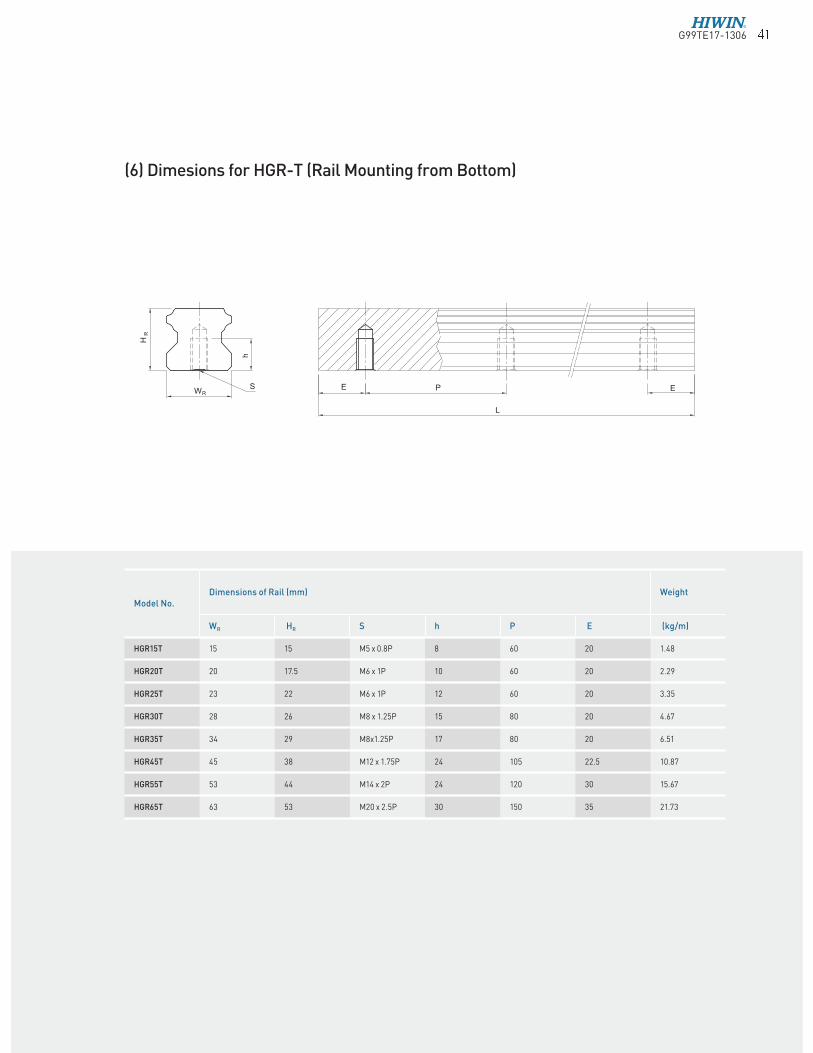
(6) Dimesions for HGR-T (Rail Mounting from Bottom)
Model No.Dimensions of Rail (mm) Weight
WR HR S h P E (kg/m)
HGR15T 15 15 M5 x 0.8P 8 60 20 1.48
HGR20T 20 17.5 M6 x 1P 10 60 20 2.29
HGR25T 23 22 M6 x 1P 12 60 20 3.35
HGR30T 28 26 M8 x 1.25P 15 80 20 4.67
HGR35T 34 29 M8x1.25P 17 80 20 6.51
HGR45T 45 38 M12 x 1.75P 24 105 22.5 10.87
HGR55T 53 44 M14 x 2P 24 120 30 15.67
HGR65T 63 53 M20 x 2.5P 30 150 35 21.73
G99TE17-1306� �