HFSS with IE-Regions
40
1 © 2015 ANSYS, Inc. November 12, 2015 ANSYS Confidential © 2014 ANSYS, Inc. November 12, 2015 ANSYS Confidential HFSS for Electrically Large Antenna System Design: Hybrid Simulation Technology Matt Commens Product Manager, HFSS ANSYS, Inc.
-
Upload
vuongkhanh -
Category
Documents
-
view
328 -
download
1
Transcript of HFSS with IE-Regions

1 © 2015 ANSYS, Inc. November 12, 2015 ANSYS Confidential © 2014 ANSYS, Inc. November 12, 2015 ANSYS Confidential
HFSS for Electrically Large Antenna System Design: Hybrid Simulation Technology
Matt Commens
Product Manager, HFSS
ANSYS, Inc.
2 © 2015 ANSYS, Inc. November 12, 2015 ANSYS Confidential © 2014 ANSYS, Inc. November 12, 2015 ANSYS Confidential
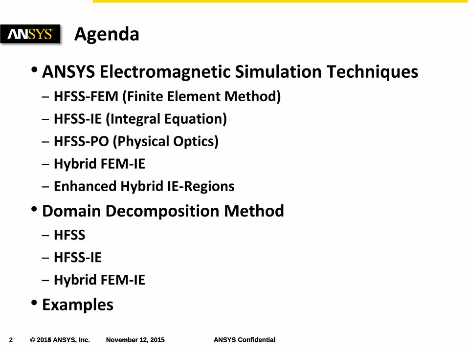
•ANSYS Electromagnetic Simulation Techniques – HFSS-FEM (Finite Element Method)
– HFSS-IE (Integral Equation)
– HFSS-PO (Physical Optics)
– Hybrid FEM-IE
– Enhanced Hybrid IE-Regions
• Domain Decomposition Method
– HFSS
– HFSS-IE
– Hybrid FEM-IE
• Examples
Agenda

3 © 2015 ANSYS, Inc. November 12, 2015 ANSYS Confidential
Full 3D System Simulations • Simulate more complicated and electrically large problems
• Require efficient simulations
HFSS 3D System Simulations
Courtesy of Raytheon

4 © 2014 ANSYS, Inc. November 12, 2015 ANSYS Confidential
3D Simulation Technology
• HFSS: 3D Finite Element Method
• HFSS-IE: 3D Method of Moments
• HFSS-IE: 3D Physical Optics (PO)
• HFSS+HFSS-IE: 3D Hybrid Simulations
Technology Review
HFSS: Cell Phone Tower
HFSS: Antenna Array

5 © 2015 ANSYS, Inc. November 12, 2015 ANSYS Confidential
3D Integral Equation (IE) technique
• Automated results with accuracy
– Automated adaptive meshing technique
• Ensures accuracy
– Adaptive Cross Approximation larger simulation
• Easy to use interface
– Common with HFSS
• Utilization of HFSS as a linked source
– Link can include effects of backwards scattering to the source geometry
Target applications:
• Large, open, radiating or scattering analyses
– Antenna placement, co-site
– Radar cross section (RCS)
HFSS-IE: 3D Method of Moments
Pass #
Delt
a S
HFSS-IE: 3D MoM with Adaptive Meshing
6 © 2015 ANSYS, Inc. November 12, 2015 ANSYS Confidential
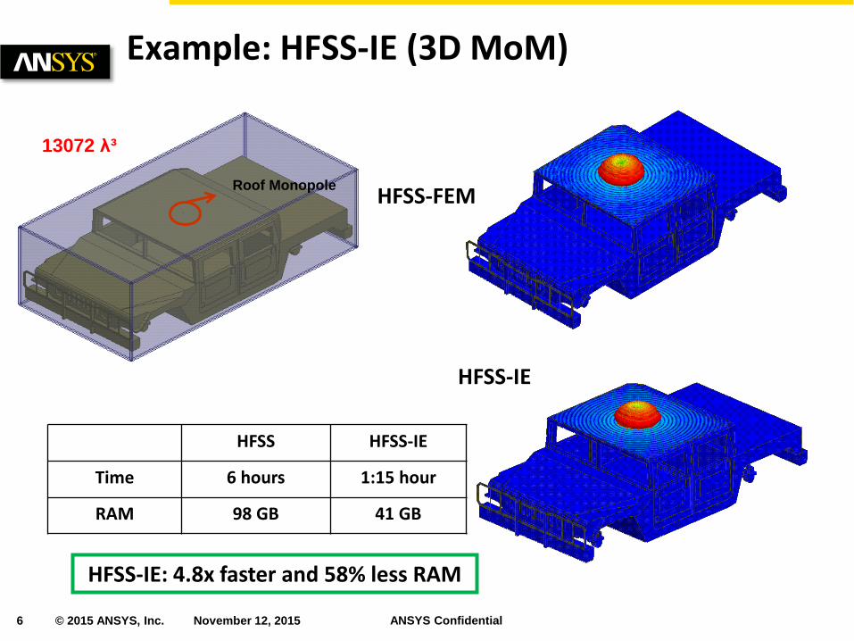
Example: HFSS-IE (3D MoM)
HFSS HFSS-IE
Time 6 hours 1:15 hour
RAM 98 GB 41 GB
13072 λ³
Roof Monopole
HFSS-IE: 4.8x faster and 58% less RAM
HFSS-FEM
HFSS-IE

7 © 2015 ANSYS, Inc. November 12, 2015 ANSYS Confidential
Asymptotic solver for large models
• Solves electrically large problems
• Currents are approximated in illuminated regions
– Set to zero in shadow regions
• Sourced by incident wave excitations
– Plane waves or linked HFSS designs as a source
Target applications:
• HFSS to PO Datalink
– Large reflector antennas
– Antenna placement on platform
• RCS of large objects such as satellites
HFSS-IE: Physical Optics (PO)

8 © 2015 ANSYS, Inc. November 12, 2015 ANSYS Confidential
Diameter = 0.667 λ
Diameter = 33.33 λ
Diameter = 6.667 λ
The higher the frequency is, the ‘more’ accurate the PO will be
IE PO IE PO IE PO
Red – PO Blue - IE
Example HFSS-IE: 3D MoM vs. Physical Optics
9 © 2014 ANSYS, Inc. November 12, 2015 ANSYS Confidential
Hybrid FEM-IE Method

10 © 2015 ANSYS, Inc. November 12, 2015 ANSYS Confidential
HFSS Hybrid Technology
• Finite Element Boundary Integral (FE-BI)
– Truncate an FEM domain with arbitrary surface using integral equations
• Hybrid IE-Regions
– FEM domains with FE-BI to a 3D Method of Moments region.
– Free Space Coupled
• Conducting objects outside of FEM solution space can be solved directly with 3D MoM
• Homogenous dielectric volumes can be removed from the FEM solution and replaced with the equivalent 3D MoM solution
– In addition IE-Regions can touch the FE-BI boundary.
• Structures can connect allowing electric current to flow from the FEM domain to 3D MoM domain
HFSS Hybrid Technology
*Requires HFSS-IE solver license
11 © 2015 ANSYS, Inc. November 12, 2015 ANSYS Confidential
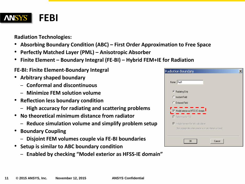
Radiation Technologies:
• Absorbing Boundary Condition (ABC) – First Order Approximation to Free Space
• Perfectly Matched Layer (PML) – Anisotropic Absorber
• Finite Element – Boundary Integral (FE-BI) – Hybrid FEM+IE for Radiation
FE-BI: Finite Element-Boundary Integral
• Arbitrary shaped boundary
– Conformal and discontinuous
– Minimize FEM solution volume
• Reflection less boundary condition
– High accuracy for radiating and scattering problems
• No theoretical minimum distance from radiator
– Reduce simulation volume and simplify problem setup
• Boundary Coupling
– Disjoint FEM volumes couple via FE-BI boundaries
• Setup is similar to ABC boundary condition
– Enabled by checking “Model exterior as HFSS-IE domain”
FEBI

12 © 2015 ANSYS, Inc. November 12, 2015 ANSYS Confidential
FE-BI significantly reduces required computer resources
• Large air volume inside of radome is removed from the FEM solution
– Air volume is required if using PML or ABC
• Two FEM-IE domains are applied
– Conformal to radome
– Conformal to horn antenna (26 GHz)
HFSS Example: FE-BI
HFSS with PML
26 GHz RAM Elapsed Time
PML 259G (DDM) 840min
FE-BI 64G 205min
19143 λ³
FE-BI shows 4.1x speedup factor and 75% less RAM HFSS with FE-BI
FEM-IE Surface
2860 λ³
Radome Horn Antenna

13 © 2015 ANSYS, Inc. November 12, 2015 ANSYS Confidential
HFSS with IE-Regions: Free Space Coupled
• Metal objects can be solved directly with an IE solution applied to surface
– Removes the need for air box to surround metal objects
• Homogeneous dielectric objects can be replaced with IE-Region
– Dielectric is solved using IE to surface
Hybrid IE-Regions: Free Space Coupled
Dielectric
εr = 4
FEM Solution (20G RAM)
IE-Regions reduces RAM by ~70%
IE-Regions (6.2G RAM)
❶Dielectric
IE-Region
❷Metallic
IE-Region

14 © 2015 ANSYS, Inc. November 12, 2015 ANSYS Confidential
❶FEM-IE domains:
Complex antenna as patch array Non-metallic parts as canopy
❷IE-Region:
metallic body, missiles etc
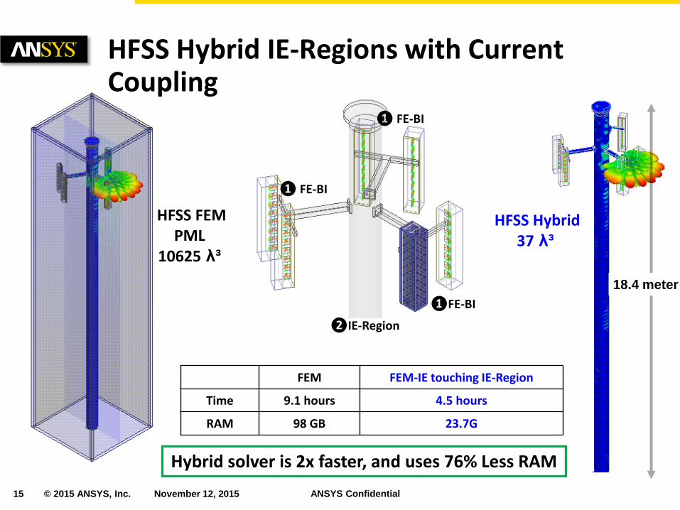
HFSS Hybrid IE-Regions • In HFSS metallic objects from IE-
Regions are allowed to touch FE-BI boundaries.
• This allows electric current coupling between Finite Elements and the 3D Method of Moments.
• Usage
– Finite elementns used to solve complex materials and excitations
– 3D Method of Moments are applied on electrically-large platform
HFSS Hybrid IE-Regions with Current Coupling
15 © 2015 ANSYS, Inc. November 12, 2015 ANSYS Confidential
HFSS Hybrid IE-Regions with Current Coupling
FEM FEM-IE touching IE-Region
Time 9.1 hours 4.5 hours
RAM 98 GB 23.7G
❷IE-Region
❶FE-BI
❶ FE-BI
❶ FE-BI
HFSS FEM PML
10625 λ³
HFSS Hybrid 37 λ³
18.4 meter
Hybrid solver is 2x faster, and uses 76% Less RAM

16 © 2015 ANSYS, Inc. November 12, 2015 ANSYS Confidential
HFSS Hybrid IE-Regions with Current Coupling
81% Less RAM: IE-Region vs. FEM
140G RAM
44G RAM
Black - FEM Red – Hybrid IE-Regions
FEM with ABC
231G RAM
22463 λ³
199 λ³
Hybrid IE-Region 44G RAM
❶FE-BI
❷IE-Region
50 λ
Continuous Current across
FEM and IE-Region

17 © 2015 ANSYS, Inc. November 12, 2015 ANSYS Confidential © 2014 ANSYS, Inc. November 12, 2015 ANSYS Confidential
Increase simulation capacity and speed with High Performance Computing
MPI Based Domain DDM
• HFSS-FEM
• HFSS-IE
• HFSS Hybrid FEM-IE and enhanced IE-Regions
Recent HPC Improvements
• New multi-threaded matrix solver
– Up to 5x faster solver vs. single core simulation
• 20% faster then previous generation multi-processing
• Improved Distributed Frequency Solver
– Multilevel HPC allowing parallel frequency points with DDM
High Performance Computing
18 © 2015 ANSYS, Inc. November 12, 2015 ANSYS Confidential © 2014 ANSYS, Inc. November 12, 2015 ANSYS Confidential
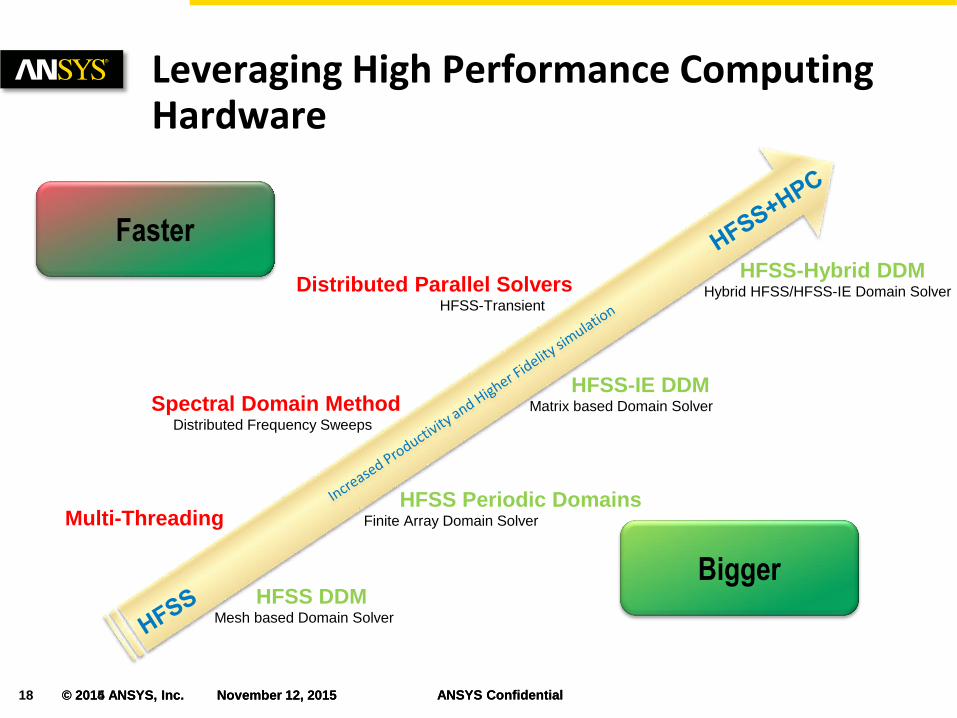
Leveraging High Performance Computing Hardware
Multi-Threading
Spectral Domain Method Distributed Frequency Sweeps
Distributed Parallel Solvers HFSS-Transient
HFSS DDM Mesh based Domain Solver
HFSS Periodic Domains Finite Array Domain Solver
HFSS-IE DDM Matrix based Domain Solver
HFSS-Hybrid DDM Hybrid HFSS/HFSS-IE Domain Solver
Faster
Bigger

19 © 2015 ANSYS, Inc. November 12, 2015 ANSYS Confidential © 2014 ANSYS, Inc. November 12, 2015 ANSYS Confidential
Multi-Threading (HPC-MT)
• Direct Matrix Solver
– Parallelized matrix solver
• Iterative Solver
– Parallelized matrix pre-conditioner
– Parallelized excitations
• Field Recovery
– Parallelized field recovery for multiple excitations
• Available with
– HFSS
– HFSS-IE
– HFSS-Transient
HPC: Multi-Threading (MT)
HFSS – HPC-MT Processor Performance* Up to 5x faster solver.
4 Cores
8 Cores
2 Cores
1 Core 1x
1.9x
3.6x
5.6x
(Baseline) No HPC
Thread 1
Thread 2 Thread 3
Thread 4
*HFSS Direct Matrix Solver

20 © 2015 ANSYS, Inc. November 12, 2015 ANSYS Confidential © 2014 ANSYS, Inc. November 12, 2015 ANSYS Confidential
Spectral Decomposition Method (HPC-SDM)
• Accelerates frequency sweeps by distributing the spectral solutions
• Increases simulation speed
– Combines with HPC-MT
• Scalable to large numbers of cores
• Available with HFSS, HFSS-IE
HPC: Spectral Decomposition Method
Frequency 1
Frequency 4
Frequency 3
Frequency 2
HFSS Frequency Sweep – HPC-SDM* Ultrafast frequency sweeps
32 SDM Points
8 SDM Points
Serial Sweep 1x
5.3x
16.6x
(Baseline) No HPC

21 © 2015 ANSYS, Inc. November 12, 2015 ANSYS Confidential © 2014 ANSYS, Inc. November 12, 2015 ANSYS Confidential
Domain Decomposition Method: Meshed Based
• Distributes mesh sub-domains to network of processors
• Significantly increases simulation capacity
• Highly scalable to large numbers of processors
– Uses industry standard MPI
– Combines with HPC-MT
• Automatic generation of domains
– User friendly
– Load balance
• Hybrid iterative & direct solver
– Multi-frontal direct solver for each sub-domain
– Sub-domains exchange information iteratively via Robin’s transmission conditions
• Available with HFSS plus HPC
HPC: HFSS-DDM (Mesh Based)
Domain 1
Domain 4
Domain 3
Domain 2

22 © 2015 ANSYS, Inc. November 12, 2015 ANSYS Confidential © 2014 ANSYS, Inc. November 12, 2015 ANSYS Confidential
Incident Wave
Domain Decomposition Method: Matrix Based
• Distributes matrix solution to network of processors
• Significantly increases simulation capacity
• Highly scalable to large numbers of machines
– Uses industry standard MPI
– Combines with HPC-MT
• Automatic generation and load balancing of matrix partitions
• Available with HFSS-IE plus HPC
HPC: HFSS-IE DDM (Matrix Based)
Domain1
Domain 3
Domain 2
Domain 4
18 GHz RAM Elapsed Time
HFSS-IE 146G 7.3h

23 © 2015 ANSYS, Inc. November 12, 2015 ANSYS Confidential © 2014 ANSYS, Inc. November 12, 2015 ANSYS Confidential
MPI Based DDM for HFSS-IE Example
1.7x Speedup with 2 HPC Pack (14% more RAM) 2.4x Speedup with 3 HPC Pack (57% more RAM)
17.4 x 13.7 x 3.1 meters 2.45GHz

24 © 2015 ANSYS, Inc. November 12, 2015 ANSYS Confidential © 2014 ANSYS, Inc. November 12, 2015 ANSYS Confidential
❷IE-Region ❶FEM-IE
❶ FEM-IE
❶ FEM-IE
Domain Decomposition Method
• Distributes mesh sub-domains to network of processors
– FEM volume can be sub-divided into multiple domains
– IE Domains will distribute when large
• Significantly increases simulation capacity and speed
• Uses industry standard MPI
• Extension of HFSS DDM to support the Hybrid FEM/IE solver
– IE Regions & FE-BI
• Available with HFSS+HFSS-IE+HPC
Hybrid HFSS-FEM with IE Regions
Domain 1
IE-Domain
Domain 3
Domain 2

25 © 2015 ANSYS, Inc. November 12, 2015 ANSYS Confidential © 2014 ANSYS, Inc. November 12, 2015 ANSYS Confidential
Hybrid HFSS - FEM DDM with IE Regions
36.2 λ
37 λ
58 λ
46 λ
>900,000 λ³
95 λ
Courtesy of Raytheon
Beam Waveguide

26 © 2015 ANSYS, Inc. November 12, 2015 ANSYS Confidential © 2014 ANSYS, Inc. November 12, 2015 ANSYS Confidential
Beam Waveguide Full-Wave Solution
FE-BI
Courtesy of Raytheon
RAM Time
Hybrid 56G 2h39m

27 © 2014 ANSYS, Inc. November 12, 2015 ANSYS Confidential
Examples

28 © 2015 ANSYS, Inc. November 12, 2015 ANSYS Confidential © 2014 ANSYS, Inc. November 12, 2015 ANSYS Confidential
F16 Antenna Placement @ 1060 MHz
4 Antennas
2 Antennas
2 Antennas
1 Antenna

29 © 2015 ANSYS, Inc. November 12, 2015 ANSYS Confidential © 2014 ANSYS, Inc. November 12, 2015 ANSYS Confidential
Only 32% longer and 26% more RAM: 4 excitations vs. 1 excitation
F16 Antenna Placement @ 1060 MHZ Adaptive Mesh
30 © 2014 ANSYS, Inc. November 12, 2015 ANSYS Confidential
Reflector Antenna (FEBI/IE-Region/PO Datalink)

31 © 2015 ANSYS, Inc. November 12, 2015 ANSYS Confidential © 2014 ANSYS, Inc. November 12, 2015 ANSYS Confidential
0.32-meter Sub-parabolic (9.6 λ)
2-meter main parabolic (60λ)
Frequency = 9GHz
Cassegrain Reflector Antenna Example
37G RAM, 3.2 hours
32 © 2015 ANSYS, Inc. November 12, 2015 ANSYS Confidential © 2014 ANSYS, Inc. November 12, 2015 ANSYS Confidential
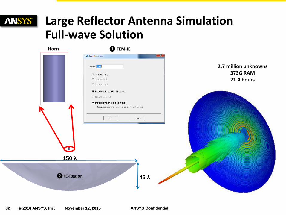
Large Reflector Antenna Simulation Full-wave Solution
2.7 million unknowns 373G RAM 71.4 hours
150 λ
45 λ
❶ FEM-IE
❷ IE-Region
Horn
33 © 2015 ANSYS, Inc. November 12, 2015 ANSYS Confidential © 2014 ANSYS, Inc. November 12, 2015 ANSYS Confidential
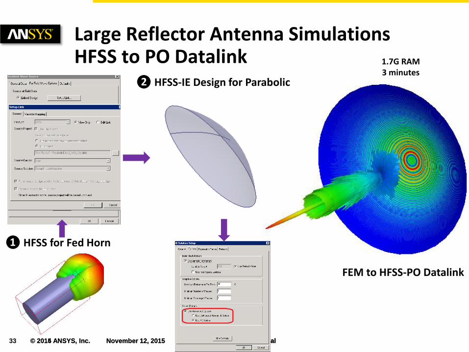
Large Reflector Antenna Simulations HFSS to PO Datalink
FEM to HFSS-PO Datalink
❶ HFSS for Fed Horn
❷ HFSS-IE Design for Parabolic
1.7G RAM 3 minutes

34 © 2015 ANSYS, Inc. November 12, 2015 ANSYS Confidential © 2014 ANSYS, Inc. November 12, 2015 ANSYS Confidential
Full-wave vs. HFSS to PO Link
Red- HFSS to PO Link Blue – Hybrid FEM-IE
Less than 0.5 dB peak-gain difference (48dB) using HFSS to PO Link

35 © 2014 ANSYS, Inc. November 12, 2015 ANSYS Confidential
RCS from Electrically-Large Models (HFSS-IE/PO)

36 © 2015 ANSYS, Inc. November 12, 2015 ANSYS Confidential © 2014 ANSYS, Inc. November 12, 2015 ANSYS Confidential
Harm RCS @ 18GHz
Red – IE Blue - PO
HFSS-IE HFSS-PO
RAM 146G 2.24G
Time 7.3 hours 4.7 minutes 246λ @ 18 GHz
Incident Wave Incident Wave
93x speedup, 98% less RAM
HFSS-IE HFSS-PO

37 © 2015 ANSYS, Inc. November 12, 2015 ANSYS Confidential © 2014 ANSYS, Inc. November 12, 2015 ANSYS Confidential
Fighter Aircraft RCS using PO
15.15 meter 910 λ @ 18GHz
10.325 meter 620 λ @ 18GHz
Incident Wave
Front View
Top View
4.19 meter 252 λ @ 18GHz
Mesh # RAM Elapsed Time
10GHz 5.03 million 15.4 G 27.5 minutes
18GHz 16.19 million 50.6G 174.5 minutes
Blue – 18GHz
Red – 10 GHz
10GHz 18GHz

38 © 2015 ANSYS, Inc. November 12, 2015 ANSYS Confidential © 2014 ANSYS, Inc. November 12, 2015 ANSYS Confidential
X-band 75-element Array on Fighter Aircraft (HFSS to PO Link)

39 © 2015 ANSYS, Inc. November 12, 2015 ANSYS Confidential © 2014 ANSYS, Inc. November 12, 2015 ANSYS Confidential
Red – Array on Fighter
Black – Array Itself
X-band 75-element Array on Fighter Aircraft (HFSS to PO Link)

40 © 2015 ANSYS, Inc. November 12, 2015 ANSYS Confidential © 2014 ANSYS, Inc. November 12, 2015 ANSYS Confidential
HFSS Hybrid solutions offers best in class solver technology
• Integrates the Finite Element Method with 3D Method of Moments
• Apply the “best” solver for the individual pieces in the entire 3D System
• Improves solver accuracy and speed
– Efficient solution of electrically large structures
HFSS with HPC runs faster and larger designs
• Domain Decomposition increases capacity by distributing the solution across a network of computers
HFSS-IE for open boundary problems
• Improved accuracy and speed for electrically large models in free space
• HFSS-IE solver scales to enable simulating multiple antennas distributed across a platform
Conclusion


![슬라이드 1huniv.hongik.ac.kr/~wave/Lecture_board/2007_1/PATCH_… · PPT file · Web view... HFSS simulation HFSS [1] HFSS [2] HFSS [3] HFSS [4] HFSS [5] HFSS [6] HFSS [7] MICROSTRIP](https://static.fdocuments.net/doc/165x107/5a8896a37f8b9a001c8e9600/-wavelectureboard20071patchppt-fileweb-view-hfss-simulation.jpg)