HFSS Antennas Arrays and FSSs - mwedatech.mweda.com/download/hwrf/hfss/HFSS-HFSS Antennas...w...
39
HFSS - Antennas, Arrays and FSS's David Perry Applications Engineer Ansoft Corporation
Transcript of HFSS Antennas Arrays and FSSs - mwedatech.mweda.com/download/hwrf/hfss/HFSS-HFSS Antennas...w...

HFSS - Antennas, Arrays and FSS's
David PerryApplications Engineer
Ansoft Corporation

Synopsis
w Some Excerpts from “What’s New”w Enhancements to HFSS
w Wave Guide Simulator (WGS)w What is it?w Why you would use it?
w Analytical Simulator (AS)w Good compliment to WGS
w Perfect Matched Layer (PML)

What’s New in Recent Versions of HFSS

HFSS Graphics: Animation Exports
w Animated Magnitude or Vector Plots can be exported as animated *.gif files
w Macro wizard interfaces walks user through animation settings
w Animations are cross-platform and can be used in presentations
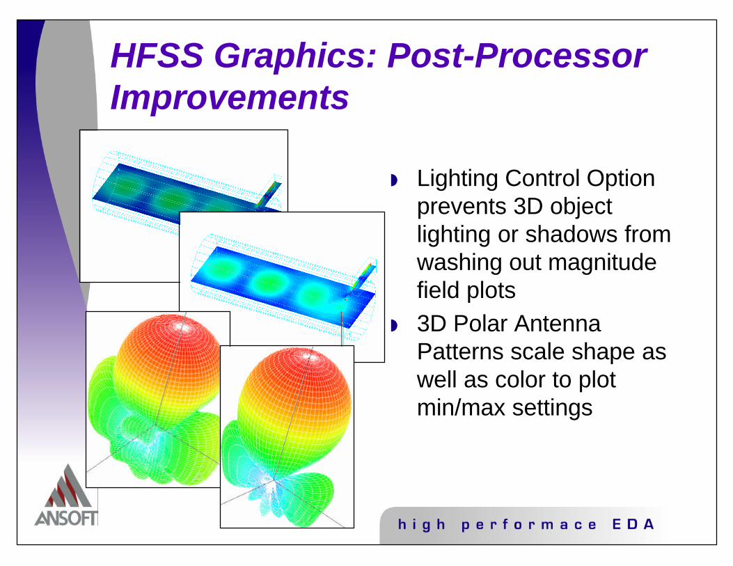
HFSS Graphics: Post-Processor Improvements
w Lighting Control Option prevents 3D object lighting or shadows from washing out magnitude field plots
w 3D Polar Antenna Patterns scale shape as well as color to plot min/max settings
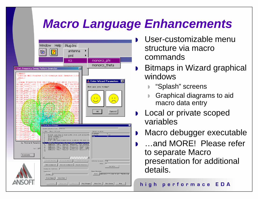
Macro Language Enhancementsw User-customizable menu
structure via macro commands
w Bitmaps in Wizard graphical windows
w “Splash” screensw Graphical diagrams to aid
macro data entry
w Local or private scoped variables
w Macro debugger executablew …and MORE! Please refer
to separate Macro presentation for additional details.
L R
C
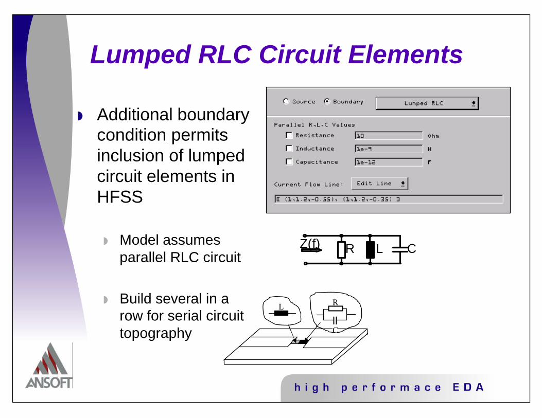
Lumped RLC Circuit Elements
w Additional boundary condition permits inclusion of lumped circuit elements in HFSS
w Model assumes parallel RLC circuit
w Build several in a row for serial circuit topography
Z(f) R L C

w Direct computation of “Total” field, rather than computation of “Scattered” field only
w Higher Accuracy, Fewer Unknowns per excitation
RCS/Scattering Solution Improvements

HFSS 8 Interpolative Sweep
w Falls between ‘fast’ and ‘discrete’ in capabilities
w Multi-decade bandwidthw Faster than Discretew No modal cutoff issuesw Fields only at mesh
frequency
w Provides wide-band sweep resultsw Calculator tool aids sweep setup if using FWS

Wide-band behavior including several sharp resonances was properly identified using very few frequency points (approximately 20).
HFSS 8 Interpolative Sweep Example

Lumped Port
Wave Port
Internal Portsw Internal ports defined with a single sheet object
at the end of the trace - no cap required.
w 2 options on how to define these ports:
w Traditional-style ports assume a perfect-H boundary on all edges that do not contact metal (wave ports)
w Gap source style (lumped ports).

Gap Source - Dipole
w Utilizing a Gap Source at feed point can improve accuracy

Meshing Improvements
Initial Lambda-Refined Mesh on a block of Vacuum and a block of
Alumina, displaying material-sensitive refinement.
w Lambda Refinement now recognizes object material assignments
w Less need to seed simply due to material conditions
w Improved convergence
w Improved mesh generation for high aspect ratios and true curved surfaces

Post3 - Moving the originw The origin can be moved
and far/near field results computed without resolving

Enough Of What’s New - So How Do I Use This Stuff?
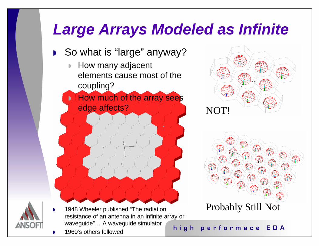
Large Arrays Modeled as Infinite
NOT!
Probably Still Not
w So what is “large” anyway?w How many adjacent
elements cause most of the coupling?
w How much of the array sees edge affects?
w 1948 Wheeler published “The radiation resistance of an antenna in an infinite array orwaveguide”… A waveguide simulator
w 1960’s others followed
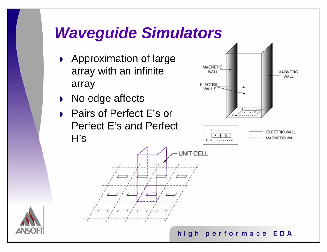
Waveguide Simulators
w Approximation of large array with an infinite array
w No edge affectsw Pairs of Perfect E’s or
Perfect E’s and Perfect H’s

Modes in a Waveguide Simulator
w Waveguide modes correspond to plane waves at angles
w Various sizes of cross sections result in different scan angles

Waveguide & Analytical Simulatorw Waveguide simulators (WGS) solve for multiple
scan anglesw Analytical simulator (AS) solves for one scan
angle. User SELECTS this angle!
* Spreadsheet is available!

Unit Cell Model of End-Fire Waveguide Array
WG Port(bottom) Ground Plane
Perfectly Matched Layer(top)
Slave BoundaryMaster Boundary
Origin
V-axis
U-axis
HFSS Boundary Descriptions: Master/Slave Boundaries
w Parameters: Coordinate system, master/slave pairing and phasing
w Master and slave boundaries used to model a unit cell of a repeating structure
w Master and slave boundaries always paired: one master to one slave
w The fields on the slave surface are constrained to be identical to those on the master surface, with phase shift
w Constraints:w The master and slave surfaces must be of
identical shapes and sizesw A coordinate system must be identified on
the master and slave boundary to identify point-to-point correspondence
Periodic Boundaries in Ansoft HFSS
w Periodic BC, Linked BC, Master/Slave Pairsw Yeah they are all the same thing!
w Adds to ability to model phased array antennasw Useful for any large uniform or periodic structurew Use to impose phase shift between two boundaries
w Multiple pairs (two or more) of matching boundariesw Can solve “staggered” antenna arrays
w Arbitrary orientation of matching boundaries in model coordinate system
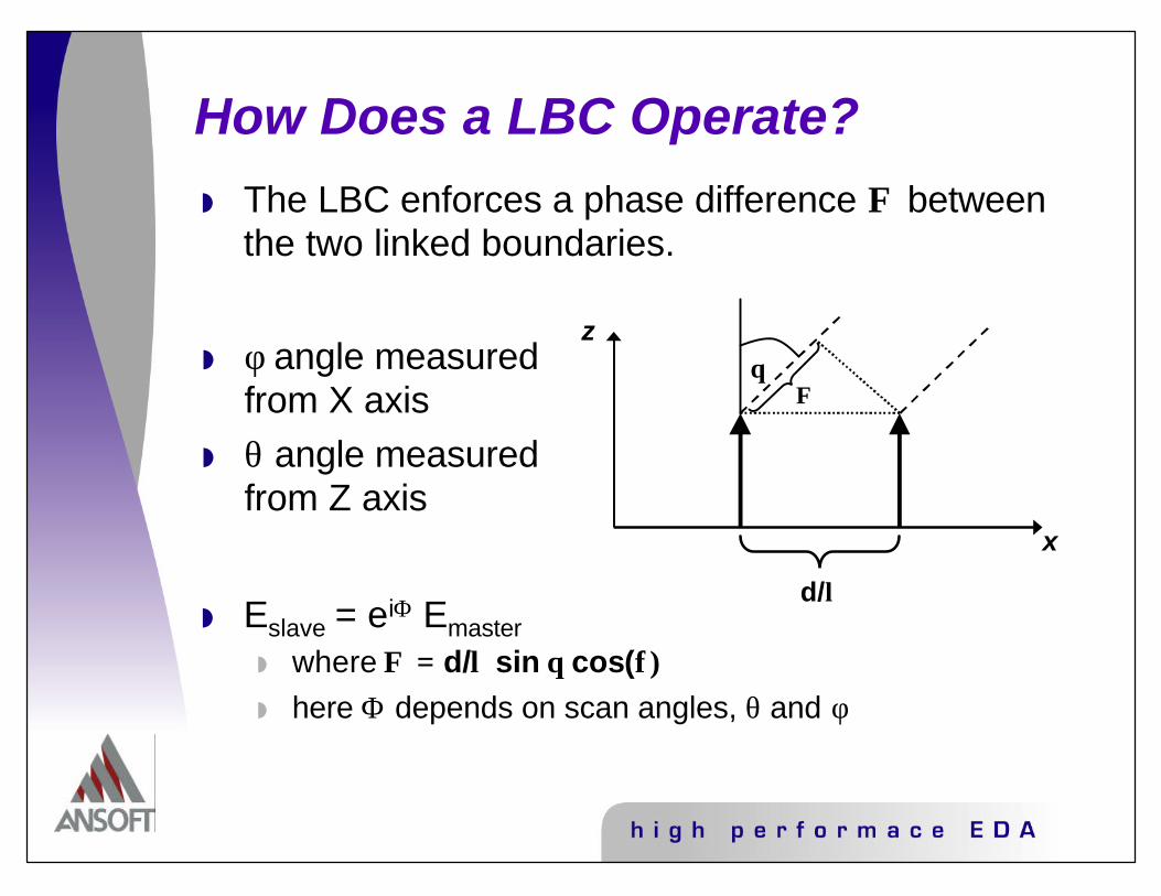
How Does a LBC Operate?w The LBC enforces a phase difference Φ between
the two linked boundaries.
w Eslave = eiΦ Emasterw where Φ = d/λ sin θ cos(φ)w here Φ depends on scan angles, θ and φ
θ
x
z
d/λ
Φw φ angle measured
from X axisw θ angle measured
from Z axis

Periodic Boundaries in Ansoft HFSS (cont)
w Boundary manager screen allows easy set-up of master and slave boundaries
w Checks that u-v coordinate choices for master and slave planes are consistent
w User provides scan angles θ and ϕ in model coordinate system
w Automatic calculation of array parameters based on model geometry
w Only model coordinate system
w Works with ABC, PML and impedance boundaries on “space port”

Space Port
Port Boundary (should NOT touch periodic boundary in HFSS)
Matching Boundary(slave)
Matching Boundary(master)
Unit Cell Boundary Conditions

MASTER 1
SLAVE 1
MA
STE
R 2
SLA
VE
2
MASTER 3 SLAVE 3
MASTER 4 SLAVE 4
Example of Skewed Array, Top View
Wondering how to create this unit cell?A macro exists to help with this!
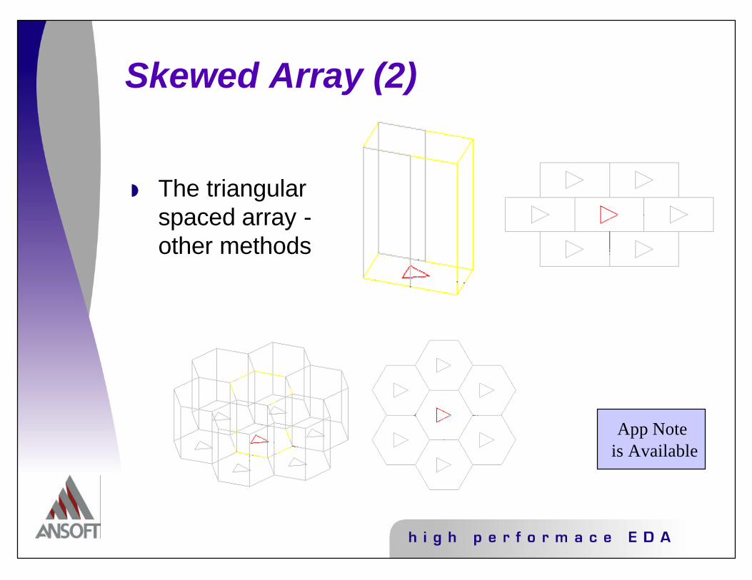
Skewed Array (2)
w The triangular spaced array -other methods
App Note is Available

Applications of Simulatorsw Arrays of driven elements
w Excitationw Traditional portw Gap Source port
w Space portsw WGS can use ports or PML’sw AS must use appropriate termination
w Frequency Selective Surface (FSS)w Excitation
w Traditional port or incident wave for WGSw Incident wave for AS
w Transmission/Reflection characteristics computed using the POST 3 calculator
w Macro exists to aid in this effort (fsswiz4.mac)
w Space portsw Same as above

PML and How to Approach the Setup
w Perfect Matched Layer (PML) w fictitious material that fully absorbs the
electromagnetic field impinging upon it w independent of incident angle
w PML requirement:w both the permeability and the permittivity be
complex anisotropic
Use “pmlcoversetup” or “dpPML” macros
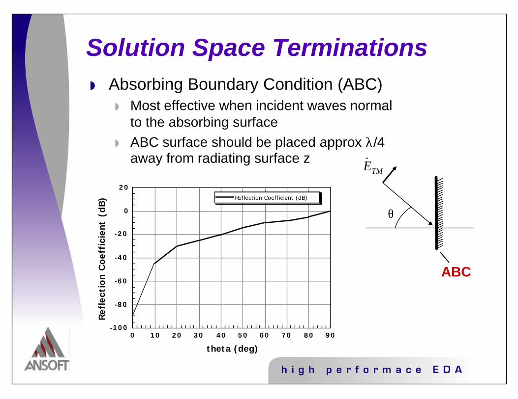
Solution Space Terminationsw Absorbing Boundary Condition (ABC)
w Most effective when incident waves normal to the absorbing surface
w ABC surface should be placed approx λ/4 away from radiating surface z
-100
-80
-60
-40
-20
0
20
Ref
lect
ion C
oef
fici
ent
(dB
)
0 10 20 30 40 50 60
theta (deg)
Reflection Coefficient (dB)
70 80 90
ABC
r E TM
θ

Solution Space Terminationsw PML
w Works well for steep angles of incidence (often occurs with wave guide simulators)
w PML does not suffer from λ/4 separation requirement (main concern is meshing)
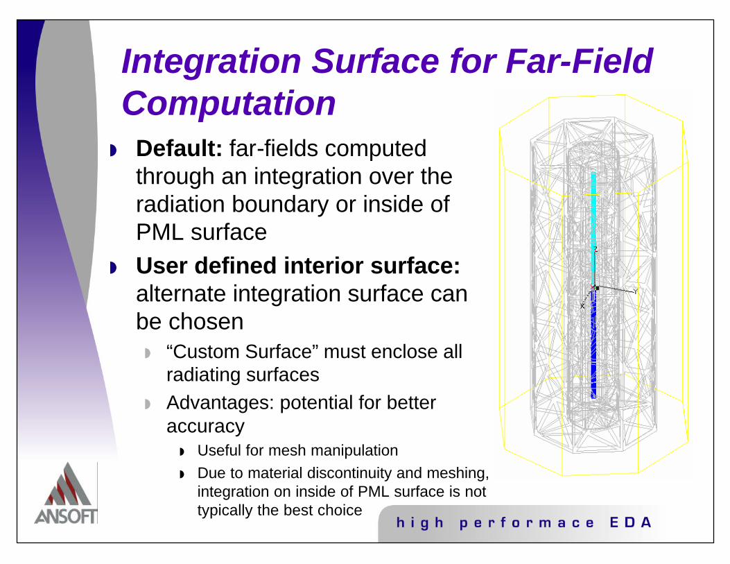
Integration Surface for Far-Field Computation
w Default: far-fields computed through an integration over the radiation boundary or inside of PML surface
w User defined interior surface:alternate integration surface can be chosen
w “Custom Surface” must enclose all radiating surfaces
w Advantages: potential for better accuracy
w Useful for mesh manipulationw Due to material discontinuity and meshing,
integration on inside of PML surface is not typically the best choice

Alternate Interior Surface (AIS)
w AIS Defined in Post-Processing
w Far-Field computation only allowed by Post 3 if:
w Radiation boundary existsor
w PML with objects names beginning with “PML…”
w Suggestion - Define face list (customer surface) first
Method:1) In the Post Processor, select radiation > compute > far field/near field2) In the “Compute Far Field” menu, check box next to “Customer Surface” then click “Set”3) This will direct you to define a set of faces from which the far fields will be calculated
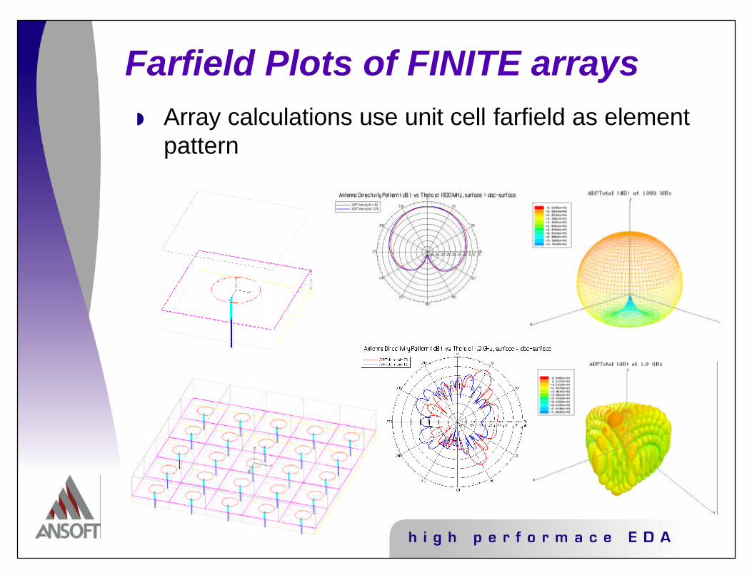
Farfield Plots of FINITE arraysw Array calculations use unit cell farfield as element
pattern

So What about FSS’s?
w Use unit cell approximationw Can use either WGS or ASw Space port at both top and
bottomw Transmission/Reflection
Characteristicsw Ports + WGS - S-parametersw Incident Wave + AS -
integrate poynting vector (*fsswiz.mac and app note available)

Further Material Availablew Docs
w AppNotePhasedArrays2.doc App Note on infinite triangular arrayw MicroJournPML.doc Discussion of LBC's and PML'sw PeriodicBCsGuide8/28/00.doc Discussion of infinite arrays in HFSSw UnitCellWriteup2.doc Discusses unit cell shapesw PML-LBC pres.pdf Further info on LBC's and PML'sw CalcCookBook.doc Great writeup on Post3 Calculator WITH
EXAMPLES!!w FSSTesting3.Doc How to for FSS’s in HFSS (draft form)
w References (Essential to understanding WGS/AS)w Hansen, Microwave Scanning Antennas Vol 2 if they are separatew IEEE AP 13 1965 page 342 Hannan Simulation of Phased Array Antenna in
Waveguidew Proc IRE Vol 36 1948 Wheeler The Radiation Resistance of an Antenna in
anInfinite Array or Waveguidew IEEE AP 13 1965 page 475 Phased Array Simulators in WG for Triangular
arranged elementsw IEEE AP 11 1963 page 377 A Technique to Simulate the Self and Mutual
Impeadances of an Array
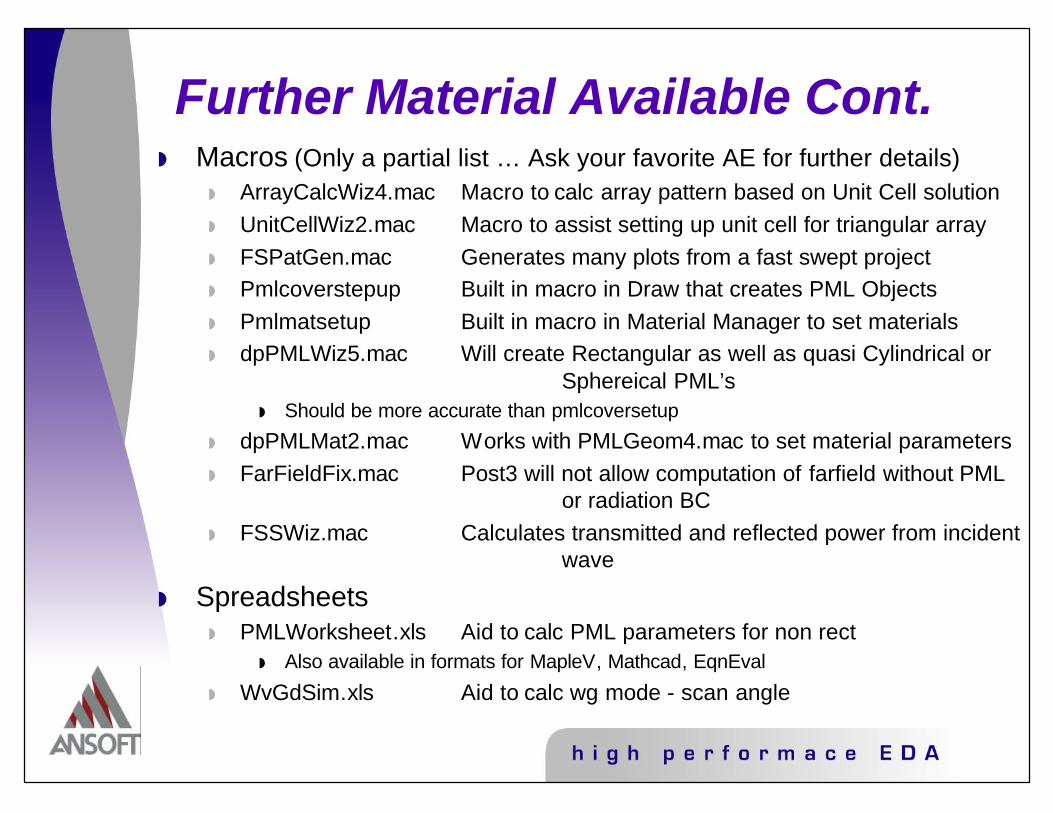
Further Material Available Cont.w Macros (Only a partial list … Ask your favorite AE for further details)
w ArrayCalcWiz4.mac Macro to calc array pattern based on Unit Cell solutionw UnitCellWiz2.mac Macro to assist setting up unit cell for triangular arrayw FSPatGen.mac Generates many plots from a fast swept projectw Pmlcoverstepup Built in macro in Draw that creates PML Objectsw Pmlmatsetup Built in macro in Material Manager to set materialsw dpPMLWiz5.mac Will create Rectangular as well as quasi Cylindrical or
Sphereical PML’sw Should be more accurate than pmlcoversetup
w dpPMLMat2.mac Works with PMLGeom4.mac to set material parametersw FarFieldFix.mac Post3 will not allow computation of farfield without PML
or radiation BCw FSSWiz.mac Calculates transmitted and reflected power from incident
wave
w Spreadsheetsw PMLWorksheet.xls Aid to calc PML parameters for non rect
w Also available in formats for MapleV, Mathcad, EqnEval
w WvGdSim.xls Aid to calc wg mode - scan angle

Closingw HFSS V8 provides both evolutionary and
revolutionary improvements to an already-powerful tool in the antenna engineer’s arsenal
w Usability Enhancements improve day to day interaction with the software
w Improvements to Existing Features speed solution times, improve accuracy, and expand the usage possibilities
w New Features permit analysis applications previously unavailable to antenna designers
w Please continue to request enhancements and added capabilities. Ansoft realizes this software is for YOUR use!

专注于微波、射频、天线设计人才的培养 易迪拓培训 网址:http://www.edatop.com
射 频 和 天 线 设 计 培 训 课 程 推 荐
易迪拓培训(www.edatop.com)由数名来自于研发第一线的资深工程师发起成立,致力并专注于微
波、射频、天线设计研发人才的培养;我们于 2006 年整合合并微波 EDA 网(www.mweda.com),现
已发展成为国内最大的微波射频和天线设计人才培养基地,成功推出多套微波射频以及天线设计经典
培训课程和 ADS、HFSS 等专业软件使用培训课程,广受客户好评;并先后与人民邮电出版社、电子
工业出版社合作出版了多本专业图书,帮助数万名工程师提升了专业技术能力。客户遍布中兴通讯、
研通高频、埃威航电、国人通信等多家国内知名公司,以及台湾工业技术研究院、永业科技、全一电
子等多家台湾地区企业。
易迪拓培训课程列表:http://www.edatop.com/peixun/rfe/129.html
射频工程师养成培训课程套装
该套装精选了射频专业基础培训课程、射频仿真设计培训课程和射频电
路测量培训课程三个类别共 30 门视频培训课程和 3 本图书教材;旨在
引领学员全面学习一个射频工程师需要熟悉、理解和掌握的专业知识和
研发设计能力。通过套装的学习,能够让学员完全达到和胜任一个合格
的射频工程师的要求…
课程网址:http://www.edatop.com/peixun/rfe/110.html
ADS 学习培训课程套装
该套装是迄今国内最全面、最权威的 ADS 培训教程,共包含 10 门 ADS
学习培训课程。课程是由具有多年 ADS 使用经验的微波射频与通信系
统设计领域资深专家讲解,并多结合设计实例,由浅入深、详细而又
全面地讲解了 ADS 在微波射频电路设计、通信系统设计和电磁仿真设
计方面的内容。能让您在最短的时间内学会使用 ADS,迅速提升个人技
术能力,把 ADS 真正应用到实际研发工作中去,成为 ADS 设计专家...
课程网址: http://www.edatop.com/peixun/ads/13.html
HFSS 学习培训课程套装
该套课程套装包含了本站全部 HFSS 培训课程,是迄今国内最全面、最
专业的HFSS培训教程套装,可以帮助您从零开始,全面深入学习HFSS
的各项功能和在多个方面的工程应用。购买套装,更可超值赠送 3 个月
免费学习答疑,随时解答您学习过程中遇到的棘手问题,让您的 HFSS
学习更加轻松顺畅…
课程网址:http://www.edatop.com/peixun/hfss/11.html
`

专注于微波、射频、天线设计人才的培养 易迪拓培训 网址:http://www.edatop.com
CST 学习培训课程套装
该培训套装由易迪拓培训联合微波 EDA 网共同推出,是最全面、系统、
专业的 CST 微波工作室培训课程套装,所有课程都由经验丰富的专家授
课,视频教学,可以帮助您从零开始,全面系统地学习 CST 微波工作的
各项功能及其在微波射频、天线设计等领域的设计应用。且购买该套装,
还可超值赠送 3 个月免费学习答疑…
课程网址:http://www.edatop.com/peixun/cst/24.html
HFSS 天线设计培训课程套装
套装包含 6 门视频课程和 1 本图书,课程从基础讲起,内容由浅入深,
理论介绍和实际操作讲解相结合,全面系统的讲解了 HFSS 天线设计的
全过程。是国内最全面、最专业的 HFSS 天线设计课程,可以帮助您快
速学习掌握如何使用 HFSS 设计天线,让天线设计不再难…
课程网址:http://www.edatop.com/peixun/hfss/122.html
13.56MHz NFC/RFID 线圈天线设计培训课程套装
套装包含 4 门视频培训课程,培训将 13.56MHz 线圈天线设计原理和仿
真设计实践相结合,全面系统地讲解了 13.56MHz线圈天线的工作原理、
设计方法、设计考量以及使用 HFSS 和 CST 仿真分析线圈天线的具体
操作,同时还介绍了 13.56MHz 线圈天线匹配电路的设计和调试。通过
该套课程的学习,可以帮助您快速学习掌握 13.56MHz 线圈天线及其匹
配电路的原理、设计和调试…
详情浏览:http://www.edatop.com/peixun/antenna/116.html
我们的课程优势:
※ 成立于 2004 年,10 多年丰富的行业经验,
※ 一直致力并专注于微波射频和天线设计工程师的培养,更了解该行业对人才的要求
※ 经验丰富的一线资深工程师讲授,结合实际工程案例,直观、实用、易学
联系我们:
※ 易迪拓培训官网:http://www.edatop.com
※ 微波 EDA 网:http://www.mweda.com
※ 官方淘宝店:http://shop36920890.taobao.com
专注于微波、射频、天线设计人才的培养
官方网址:http://www.edatop.com 易迪拓培训 淘宝网店:http://shop36920890.taobao.com