HA325 - slot techslot-tech.com/interesting_stuff/sencore/HA325/HA325... · · 2014-01-17Guide to...
64
HA325 HA325 HORIZONTAL OUTPUT & FLYBACK ANALYZER Operation and Application Manual 3200 Sencore Drive, Sioux Falls, South Dakota 57107
Transcript of HA325 - slot techslot-tech.com/interesting_stuff/sencore/HA325/HA325... · · 2014-01-17Guide to...

HA325HA325HORIZONTAL OUTPUT & FLYBACK
ANALYZER
Operation and Application Manual
3200 Sencore Drive, Sioux Falls, South Dakota 57107

Every precaution has been taken in the design of the HA325 to insure that it is as safe aspossible. However, safe operation depends on you, the operator.
1. Never exceed the limits of this instrument as given in the specifications section and theadditional special warnings in this manual.
2. A severe shock hazard can result if the chassis of the equipment being serviced is tied tothe “hot” side of the AC line. An isolation transformer should always be used with hot-chassis equipment. Also be sure that the top of your workbench and floor underneath it aredry and made of non-conductive materials.
3. Remove the circuit power before making connections to high voltage circuits or circuitpoints.
4. Discharge filter capacitors (after removing power) before connecting to any part of thecircuit requiring power to be removed.
5. Be sure your equipment is in good order. Broken or frayed test leads can be extremelydangerous and expose you to dangerous voltages.
6. Remove the test lead immediately after the test has been completed to reduce the possibilityof shock.
7. Do not work alone when working on hazardous circuits. Always have another personclose by in case of an accident.
8. Improper Fuse(s) Void Warranty. Fuses are for your protection, so always replace fusewith the proper type and current rating. Type and ratings are listed near the fuse holder. Onunits with more than one fuse, be sure you are replacing the proper fuse value in the fuseholder.
9. Study the procedures in this manual carefully and note special warnings and cautionsbefore using this test instrument.
WARNING
PLEASE OBSERVE THESE SAFETY PRECAUTIONS
There is always a danger present when using electronic test equipment. Unexpectedvoltages can be present at unusual locations in defective equipment and distribution systems.Become familiar with the equipment with which you are working and observe the followingsafety precautions.

HA325HA325HORIZONTAL OUTPUT & FLYBACK
ANALYZER
Operation and Application Manual
3200 Sencore Drive, Sioux Falls, South Dakota 57107

TABLE OF CONTENTSSAFETY PRECAUTIONS………Inside Front Cover
DESCRIPTIONIntroduction …………………………………………1 Features ……………………………………………1 Specifications………………………………………2 Front Controls & Side Panel Features …………….4 Accessories…………………………………………6
OPERATIONIntroduction…………………………………………..7Preparation for Use …………………………………7 Power Connection …………………………………7 Battery Testing and Charging………………………7 Battery Power Management ………………………..9 Load Test Fuse Replacement……………………….9 Assistance Display Messaging…………………….10
Horizontal Output Load Test ……………………….11 Load Test Display Windows………………………11 Understanding the HORIZ. OUTPUT Load Test…12 Horizontal Frequency Generator ………………….13 The Load Test VDC Power Supply ………………13 Test Lead Connections – HORIZ. OUTPUT Load Test ….………………14 Selecting a Setup Option – SETUP OPTIONS-HOR ..….….……….………16 Using SETUP Values –SETUP HORIZ. OUTPUT.17 Performing the HORIZ. OUTPUT Load Test .……18 Interpreting HORIZ. OUTPUT mA, % EFF and µS Readings……….………….………………20Flyback & IHVT Load Test…………………………21 Understanding the FLYBACK & IHVT Load Test..22 Test Lead Connections – FLYBACK & IHVT Load Test ..…….…………23 Selecting a Setup Option – SETUP OPTIONS-FLY .….…………….………24 Using SETUP Values –SETUP FLYBACK/IHVT..25 Performing the FLYBACK/IHVT Load Test ..……26 Interpreting FLYBACK/IHVT mA, % EFF and µS Readings...………….……………27Ringer Tests…………………………………………27 Performing the Ringer Tests ………………………28
APPLICATIONSIntroduction …………………………………………29 Understanding Horizontal Stages of a CRT Video Display ……………………………………………29 Understanding Horizontal Troubleshooting Difficulties…………………………………………30 Guide to the HA325Tests…..………………………32 Connecting the Load Test Leads without a Schematic.…………………………………………32 Understanding the Auto Setup – HORIZ. OUTPUT Load Test……………………34 Interpreting the Load Test mA Readout....…………35 Interpreting the Load Test % Readout ……………37 Interpreting the Load Test µS Readout ……………38 Troubleshooting High mA & Low % EFF Load Test Readouts...……………………………………41 Troubleshooting Unusual µS Readouts ……………43 Understanding IHVT Failures .…………………….44 Analyzing a Flyback or IHVT for a Shorted Turn …45 Analyzing a Flyback or IHVT for Primary to Secondary Shorts..…………………………………46 Analyzing the IHVT’s HV Multiplier Section..……47 Analyzing the IHVT’s Focus & Screen Divider Section..……………………………………………49 Testing an IHVT for HV Multiplier to Secondary Shorts………………………………………………51 Troubleshooting Horiz. Output Stage AC Loading Defects..……………………………………………52
MAINTENANCEIntroduction …………………………………………55 Replacing the Internal Battery Pack..………………55 Replacing the Internal Load Test Switching Transistor..…………………………………………56 Replacing the Load & Ringer Test Lead……………56 Updating the HA325 Operating Firmware…………58
WARRANTY & SERVICE..…… Inside Back Cover
DESCRIPTIONINTRODUCTION
There are many display monitors today incomputer, medical, security, design, gamingand industrial applications. These displaysoperate at many different horizontal scanningfrequencies and picture resolutions. Someoperate at a single scanning frequency whileothers switch to properly display video atmany scanning frequencies.
All CRT (cathode ray tube)-based displayshave a horizontal output stage to produce highvoltage and deflection. This can be done witha single horizontal output stage or separatehorizontal output stages. Despite the widerange of horizontal operating frequencies anduses, several basic horizontal output stageconfigurations are used and can be analyzedusing universal tests.
Horizontal output stages and their relatedcircuits account for many defects anddifficult-to-troubleshoot symptoms. Closeinteraction between stages, momentaryvoltages, high currents, repeat componentfailures and the inability to reduce the outputvoltage from a switch mode power supply areto blame.
Video displays that operate at multiplescanning frequencies maintain proper highvoltage and deflection by switching incomponents in the horizontal output stageand/or using high voltage or deflectionregulator stages. These circuits and switchedcomponents add further complexity andtroubleshooting difficulty.
FEATURES
The HA325 provides exclusive analyzingtests of horizontal output stages,flyback/IHVT transformers, inductors, andswitching transformers to localize horizontalcircuit defects faster than conventionalmethods. Its exclusive Load Tests and RingerTests isolate defects that previously requiredmany hours of expensive troubleshooting orcomponent swapping.
The HA325 provides a “chassis off” LoadTest of the horizontal output stage todetermine if the stage is free of severe defectsor if problems exist. The Load Test simulatesthe operation of the horizontal output stage ator near 1/10 of its normal level and analyzesthe resulting current and voltages. TheHorizontal Output Load Test is valuable indetermining if defects are in the horizontaloutput stage or the main power supply and/or
if circuit problems caused the horizontaloutput transistor to fail. It’s also helpful inisolating horizontal defects that would causecomponent damage or high voltage shutdownif AC power were applied to the display.
The HA325 provides a test of integrated highvoltage transformers (IHVTs) or flybacktransformers to determine if primary tosecondary shorts, loading/efficiency defectsor integrated multiplier section defects exist.The Flyback & IHVT Load Test establishes atest circuit in which the flyback or IHVT isplaced into a tuned horizontal output stage ateither a TV or high scan frequency. In amanner similar to the Horizontal Output LoadTest, a setup is established and the currentsand voltages analyzed to identify flyback orIHVT defects.
1

The Flyback & IHVT Load Test can also beused in-circuit to isolate a loading defect tothe flyback and its secondary load circuits orto the primary circuitry of the horizontaloutput.
The HA325 Ringer Test is a componentanalyzing test of a flyback or IHVTtransformer, coil or switching transformer.These components commonly fail from one ormore internal wire turns shorting together. Ashorted turn lowers the Q of the inductor andperformance of the circuit, but is difficult toconfirm, as it causes little change to theinductor value or winding resistance of the
coil. A Ringer Test identifies inductor ortransformers with shorted turns for confidentdiagnosis and replacement.
The small battery operated HA325 is wellsuited to take to the home or commercial siteto help in isolating horizontal or power supplyrelated symptoms in HD- ready televisions,CRT video projection systems, displaymonitors, gaming monitors and the like. It’salso well suited to pass from bench to benchor from technician to technician to get themaximum return on your test equipmentinvestment.
SPECIFICATIONS
HORIZONTAL FREQUENCY GENERATOR FUNCTION: Square wave generator for Load Tests FREQUENCY RANGE (HORIZ. OUTPUT): 15 kHz to 125 kHz (.5kHz steps) FREQUENCY RANGE (IHVT/FLYBACK SETUP): 15-40kHz (1kHz steps)
LOAD TEST B+ POWER SUPPLY VOLTS RANGE: 0 - 18 VDC (.1 volt steps) CURRENT LIMIT: 200 mA ± 10% PROTECTION: 200 V (DC + Peak)
LOAD TEST SETUP EXCITATION DRIVE: Square wave 50% duty-cycle ± 2% FREQ. READOUT ACCURACY: ± 250 Hz DCV READOUT ACCURACY: ± .2 volts VPP RANGE: auto-ranged 0 - 300 VPP VPP RESOLUTION: 1 volt VPP ACCURACY: ± 1%, ± 2 counts (20 kHz) VPP FREQ. RESPONSE: 10 kHz - 125 kHz ± 1 dB SETUP OPTIONS (HORIZ. OUTPUT):
AUTO: Automatically selects setupTV: Frequency = 16kHz, VDC=13VHD1080 33kHz: Frequency = 33 kHz, VDC = 11.5VHD720 45kHz: Frequency = 45 kHz, VDC = 12VVESA 38 kHz: Frequency = 38 kHz, VDC = 10VVESA 48 kHz: Frequency = 48 kHz, VDC = 10V
VESA 64kHz: Frequency = 67 kHz, VDC = 10VVESA 75kHz: Frequency = 75 kHz, VDC = 12V
2

VESA 88 kHz: Frequency = 88 kHz, VDC = 12 VMANUAL: Adjustable beginning 30 kHz, 1V
SETUP OPTIONS: (FLYBACK & IHVT)AUTO: Automatically selects setupTV: Frequency = 16 kHz, VDC = 13VHI-SCAN: Frequency = 25 kHz, VDC = 13VMANUAL: Adjustable beginning 20 kHz, VDC = 1V
LOAD TEST B+ mA RANGE: 0 - 200 mA (HORIZ. OUTPUT) B+ mA RESOLUTION: 1 mA B+ mA ACCURACY: ± 1%, ± 2 counts TIME µS RANGE: .1 µS - 40 µS TIME µS ACCURACY: ± 1%, ± 2 counts TIME µS RESOLUTION: .1 µS TIME µS TRIGGER LEVEL: 5% ±1% of pos.
pulses with PPV > 10 VPP EFFICIENCY RANGE: 0 - 99% EFFICIENCY ACCURACY: ± 2%, ± 1 count EFFICIENCY RESOLUTION: 1% PROTECTION: Diode & Fuse, 400 volts (DC + Peak)
RINGER TEST FUNCTION: Approximate coil Q determined by exciting coil and counting ringing cycles to a damped level. INDUCTOR RANGE: 10 µH or higher, non-iron core EXCITATION VOLTAGE: 5 volts SENSITIVITY LEVEL: Yokes & flybacks -25%, Coils 5% (Ref. first cycle) ACCURACY: ± 1 count from 8 to 13 rings PROTECTION: 200 volts (DC + Peak)
General CASE SIZE: 2” x 5” x 10.5” WEIGHT: ~ 2 lbs. DISPLAY: LCD (20 X 4 row characters) POWER: 105-125VAC (AC/DC Adapter 14V, 700 mA (Sencore PA273) BATTERY: Rechargeable Nickel Metal Hydride Pack (7.2V 1500 AH) TEMPERATURE: 5-35 degree C. HUMIDITY: 0-90% no condensation WARMUP: All specifications allow for 20 minute warm-up and are guaranteed at 5-35º C.
3

FRONT CONTROLS AND SIDE PANEL FEATURES
1. DIGITAL DISPLAY – Displays setupoptions & values, user information, testresults and assistance messages.
2. LOAD TEST FUSE – Protects theHA325 test circuitry from an energizedcircuit or stored circuit charge.
3. LOAD & RINGER TEST LEAD –Provides connection for the Load &Ringer Test Lead.
4. RS232 INTERFACE BUS – Providescomputer connection to update firmware.
5. AC POWER ADAPTER INPUT –Provides input for connecting the poweradapter (PA273) to the HA325.
6. TEST/SETUP pushbutton - Switchesthe display between the SETUP displaywindow or LOAD TEST display windowduring the HORIZ. OUTPUT andFLYBACK & IHVT Load Tests.
7. ENTER pushbutton - Enters a setupoption, kHz value, or VDC value whenincrementing with the UP ARROW andDOWN ARROW pushbuttons.
8. RINGER TESTS SWITCHINGXFORMER pushbutton – Selects theRinger Test designed to test switchingtransformers for a shorted turn.
9. ASSISTANCE pushbutton – Providesassistance messages while performingsetups or tests.
10. POWER ON/OFF pushbutton –Provides or removes power and provides abattery test.
11. RINGER TESTS COILS pushbutton –Selects the Ringer Test designed to testinductors and coils for a shorted turn.
12. RINGER TESTS YOKES &FLYBACKS pushbutton - Selects theRinger Test designed to test yokes andflybacks for a shorted turn.
13. DOWN ARROW pushbutton - Movesthe display cursor downward to selectfrom the SETUP OPTIONS during setupof the Horiz. Output or Flyback & IHVTLoad Tests. Decreases kHz or VDCvalues in the SETUP display during amanual setup.
14. UP ARROW pushbutton – Moves thedisplay cursor upward to select from theSETUP OPTIONS during setup of theHoriz. Output or Flyback & IHVT LoadTests. Increases kHz or VDC values in theSETUP display during a manual setup.
15. LOAD TEST HORIZ. OUTPUTpushbutton – Selects the HorizontalOutput Load Test and initiates the setupprocess.
16. LOAD TEST FLYBACK & IHVTpushbutton – Selects the Flyback &IHVT Load Test and initiates the setupprocess.
4

HA325
Fig. 1: Front panel controls and side panel features.
5

ACCESSORIES
17. TP212 X10 Multiplier probe: Increasesa 15 megohm impedance DC meter to 150megohms for measuring flyback or IHVToutput voltages during the Load Test.(Optional)
18. AC POWER ADAPTER/CHARGER(Part #PA273) – Plugs into the DC Inputjack to recharge the battery or provide ACoperation. (Provided)
19. PROTECTIVE/STORAGE COVER:(Part #CC296) Provides a protectivecover and a convenient storage pouch to
store the attached LOAD & RINGERTEST CABLE. (Optional)
20. FUSED DC POWER LEAD : (Part #39G355) Plugs into the DC Input Jack topower the unit from any 12 volt negative-ground vehicle lighter. (Optional)
21. NULL-MODEMCOMMUNICATIONS CABLE: (Part#39G523) Connects between thecommunications port of a computer andthe RS232 Interface Bus connector (4).(Optional)
Fig. 2: Accessories
6
OPERATIONINTRODUCTION
You should take a few minutes to read thissection of the manual before operating theHA325. It explains how its unique tests work,along with how to use and interpret the tests.This section of the manual includes 4 mainsections: 1) Preparation For Use, 2)Horizontal Output Load Test, 3) Flyback &IHVT Load Test and 4) Ringer Tests.
Once you become familiar with the tests, youcan operate the HA325 from the displaywindow and assistance messages provided.The APPLICATIONS section of this manualprovides more information on using andinterpreting the HA325 tests. The MAIN-TENANCE section of this manual coversfirmware updates and internal battery,transistor and lead replacement.
PREPARATION FOR USE
The HA325 is ready for use when you removeit from its packing material. The test lead isattached to the HA325 so it cannot be lostduring portable applications. The AC PowerAdapter/Charger and the Operation &Application Manual is shipped with theHA325. Additional product and companysupport information may also be included.Carefully unpack the HA325 and confirm youhave received these supplied items.
Power Connection
The HA325 is powered from an internalbattery or an external AC PowerAdapter/Charger to convert the standard 105-125 VAC, 50/60 Hz AC line voltage to 14VDC. The AC Power Adapter/Charger(Sencore #PA273) is detachable from theHA325.
To power the HA325 with the AC PowerAdapter/Charger connect it to a 105-125 VACpower receptacle. Attach the AC PowerAdapter/Charger’s miniature plug to the ACAdapter Input Jack located on the side panel.The unit is powered for normal operation by
momentarily pressing the POWER ON/OFFbutton in the bottom left corner of the HA325.The digital display will illuminate, indicatingthe HA325 is powered on.
When powered on, pressing & holding downthe POWER ON/OFF pushbutton will displaya “CHARGING” display message, indicatingthe Power Adapter/Charger is powering theHA325 and charging its internal battery. Abattery symbol in the upper right corner of thedisplay increments upward, providing acontinuous indication that the power adapteris connected and is charging the internalbattery.
Battery Testing & Charging
The HA325 has an internal batterycompartment containing a standardrechargeable Nickel Metal Hydride batterypack. The battery pack requires no specialmaintenance, however some care in operatingprocedures can optimize the battery life.
7
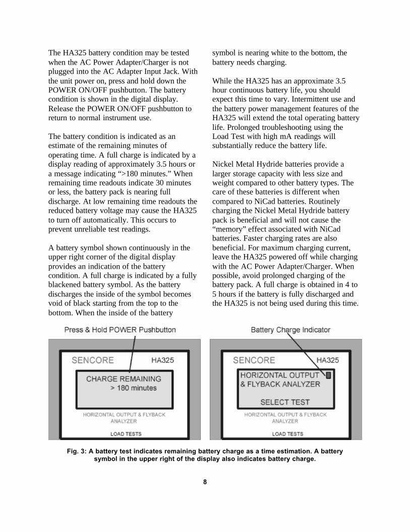
The HA325 battery condition may be testedwhen the AC Power Adapter/Charger is notplugged into the AC Adapter Input Jack. Withthe unit power on, press and hold down thePOWER ON/OFF pushbutton. The batterycondition is shown in the digital display.Release the POWER ON/OFF pushbutton toreturn to normal instrument use.
The battery condition is indicated as anestimate of the remaining minutes ofoperating time. A full charge is indicated by adisplay reading of approximately 3.5 hours ora message indicating “>180 minutes.” Whenremaining time readouts indicate 30 minutesor less, the battery pack is nearing fulldischarge. At low remaining time readouts thereduced battery voltage may cause the HA325to turn off automatically. This occurs toprevent unreliable test readings.
A battery symbol shown continuously in theupper right corner of the digital displayprovides an indication of the batterycondition. A full charge is indicated by a fullyblackened battery symbol. As the batterydischarges the inside of the symbol becomesvoid of black starting from the top to thebottom. When the inside of the battery
symbol is nearing white to the bottom, thebattery needs charging.
While the HA325 has an approximate 3.5hour continuous battery life, you shouldexpect this time to vary. Intermittent use andthe battery power management features of theHA325 will extend the total operating batterylife. Prolonged troubleshooting using theLoad Test with high mA readings willsubstantially reduce the battery life.
Nickel Metal Hydride batteries provide alarger storage capacity with less size andweight compared to other battery types. Thecare of these batteries is different whencompared to NiCad batteries. Routinelycharging the Nickel Metal Hydride batterypack is beneficial and will not cause the“memory” effect associated with NiCadbatteries. Faster charging rates are alsobeneficial. For maximum charging current,leave the HA325 powered off while chargingwith the AC Power Adapter/Charger. Whenpossible, avoid prolonged charging of thebattery pack. A full charge is obtained in 4 to5 hours if the battery is fully discharged andthe HA325 is not being used during this time.
Fig. 3: A battery test indicates remaining battery charge as a time estimation. A batterysymbol in the upper right of the display also indicates battery charge.
8
Battery Power Management
The HA325 provides several battery powermanagement features during battery operationto extend the useable time provided by eachbattery charge cycle. Battery powermanagement features reduce the batterypower being consumed by the HA325 whenthe instrument is powered on but is not beingused for testing. The HA325 includes threelevels of power management including: 1)display back light disable, 2) standby modeand 3) power shutdown. The powermanagement functions are defeated when theAC Power Adapter/Charger is connected tothe HA325.
The first level of power management disablesthe back light of the digital display if no frontpanel pushbuttons are pushed in 60 seconds.All HA325 test functions remain active.Pressing a front panel button will select thefunction pressed and restore the display light.To restore the light while performing a LoadTest without changing functions, press theTEST/SELECT pushbutton twice, whichtoggles between setup and test windows. Youmay also momentarily press the up arrow,down arrow, ENTER or ASSISTANCEpushbuttons to restore the display back lightwithout disrupting the test.
The second level of battery powermanagement is a standby mode, initiatedwhen no front panel pushbutton is pressed for5 minutes. Standby removes the test voltageof the Load Test and reduces internal powerdrain on the battery. “STANDBY” readout isshown on the display to indicate a standbymode. Standby operation is preceded by audiotones at 2 minutes remaining (3 beeps), 1
minute remaining (2 beeps) and standbybegins (1 beep). If you have completedtesting, the beeps remind you to turn the
HA325 off to extend the battery life. Pressingany of the front panel pushbuttons in theStandby mode, except the POWERpushbutton, restores the previous test or setupfunction.
The final level of battery power managementis power shutdown. Power shutdown occursafter approximately 5 minutes in the standbymode if no front panel pushbuttons arepressed. An audio beep is produced by theHA325 each minute in the standby mode.Once power is shutdown the POWER buttonmust be pressed to again turn the HA325 onfor normal use.
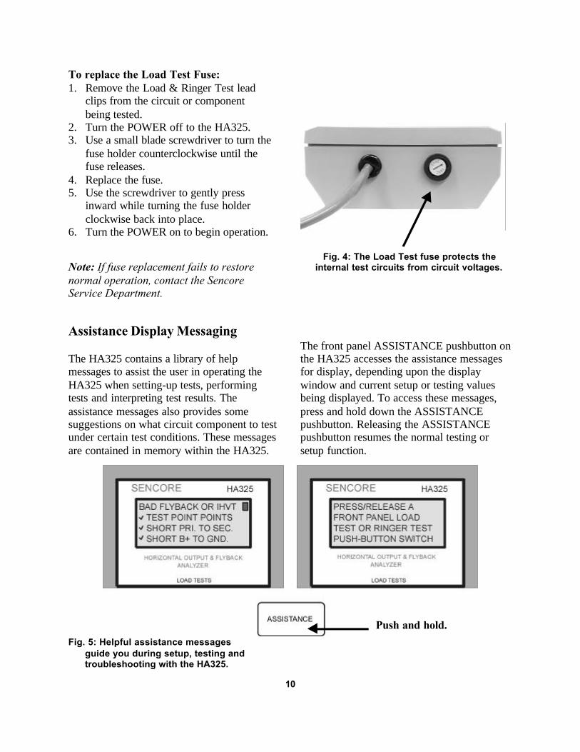
Load Test Fuse Replacement
A fuse protects the Load Test circuitry of theHA325 from voltages and charges that maybe present in the chassis or components beingtested. For ease of replacement, the fuse islocated on the top side panel of the HA325near the Load & Ringer Test Lead input. Thefuse is a 1 amp 3AG fast blow fuse.
The Load Test fuse is monitored by internalcircuits of the HA325 to detect when it hasopened. This prevents wasted time andpossible errors performing the Load Testwhen the fuse is bad. If the fuse opens or ismissing, the digital display indicates“REPLACE LOAD TEST FUSE 1AMP.FAST- BLOW.”
9
To replace the Load Test Fuse:1. Remove the Load & Ringer Test lead
clips from the circuit or componentbeing tested.
2. Turn the POWER off to the HA325.3. Use a small blade screwdriver to turn the
fuse holder counterclockwise until thefuse releases.
4. Replace the fuse.5. Use the screwdriver to gently press
inward while turning the fuse holderclockwise back into place.
6. Turn the POWER on to begin operation.
Note: If fuse replacement fails to restorenormal operation, contact the SencoreService Department.
Fig. 4: The Load Test fuse protects theinternal test circuits from circuit voltages.
Assistance Display Messaging
The HA325 contains a library of helpmessages to assist the user in operating theHA325 when setting-up tests, performingtests and interpreting test results. Theassistance messages also provides somesuggestions on what circuit component to testunder certain test conditions. These messagesare contained in memory within the HA325.
The front panel ASSISTANCE pushbutton onthe HA325 accesses the assistance messagesfor display, depending upon the displaywindow and current setup or testing valuesbeing displayed. To access these messages,press and hold down the ASSISTANCEpushbutton. Releasing the ASSISTANCEpushbutton resumes the normal testing orsetup function.
Fig. 5: Helpful assistance messages guide you during setup, testing and troubleshooting with the HA325.
10
Push and hold.

HORIZONTAL OUTPUT LOAD TESTThe Horiz. Output Load Test provides afunctional test of the horizontal output stagewith no AC applied to the chassis. The LoadTest quickly confirms if the horizontal outputstage is free of severe defects or if problemsexist. The Load Test is useful in determiningrepair costs, troubleshooting horizontal outputstage defects and determining when it is safeto apply AC voltage to the chassis.
This section familiarizes you with the Horiz.Output Load Test. It explains how to properlysetup and perform the Load Test and furtherexplains the three readouts displayed duringthe Load Test.
Load Test Display Windows
The HA325 has three digital display windowsthat are used when performing the HORIZ.OUTPUT and FLYBACK & IHVT LoadTests. Three display windows used by theHA325 step you through the setup and testingprocess. The display windows include: 1)SETUP OPTIONS, 2) SETUP and 3) TESTdisplay windows.
The SETUP OPTIONS display window isshown immediately after selecting a LoadTest by pressing the HORIZ. OUTPUT orFLYBACK & IHVT front panel pushbutton.This display window shows a list of optionsfor establishing a horizontal test frequencyand DC voltage to the horizontal output stageor flyback/IHVT being tested. Optionsinclude a fully automatic setup (AUTO),preset options (TV, etc.) or a manual(MANUAL) setup.
The SETUP display window shows theresulting frequency and DC voltage beingapplied to the horizontal output stage orflyback/IHVT as a result of the optionselected in the SETUP OPTIONS displaywindow. A VPP readout is also shown
indicating the resulting flyback pulseamplitude being produced by the appliedsetup. The SETUP display window followsthe SETUP OPTIONs window when aMANUAL setup is selected. With all othersetup options, a SETUP display may beselected by pressing the TEST/SETUPpushbutton when the TEST display window isshown.
The TEST display window shows testmeasurements (mA, % EFF, µS) in either theHoriz. Output or Flyback & IHVT LoadTests. This display follows all setup optionchoices when entered during the SETUPOPTIONS display window. This displaywindow also follows all SETUP displaywindows when the TEST/SETUP pushbuttonis pressed.
Fig. 6: Three display windows used forthe HA325 Load Tests
11
Understanding the HORIZ.OUTPUT Load Test
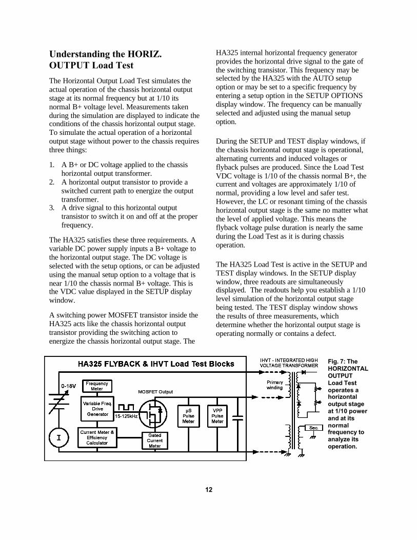
The Horizontal Output Load Test simulates theactual operation of the chassis horizontal outputstage at its normal frequency but at 1/10 itsnormal B+ voltage level. Measurements takenduring the simulation are displayed to indicate theconditions of the chassis horizontal output stage.To simulate the actual operation of a horizontaloutput stage without power to the chassis requiresthree things:
1. A B+ or DC voltage applied to the chassishorizontal output transformer.
2. A horizontal output transistor to provide aswitched current path to energize the outputtransformer.
3. A drive signal to this horizontal outputtransistor to switch it on and off at the properfrequency.
The HA325 satisfies these three requirements. Avariable DC power supply inputs a B+ voltage tothe horizontal output stage. The DC voltage isselected with the setup options, or can be adjustedusing the manual setup option to a voltage that isnear 1/10 the chassis normal B+ voltage. This isthe VDC value displayed in the SETUP displaywindow.
A switching power MOSFET transistor inside theHA325 acts like the chassis horizontal outputtransistor providing the switching action toenergize the chassis horizontal output stage. The
HA325 internal horizontal frequency generatorprovides the horizontal drive signal to the gate ofthe switching transistor. This frequency may beselected by the HA325 with the AUTO setupoption or may be set to a specific frequency byentering a setup option in the SETUP OPTIONSdisplay window. The frequency can be manuallyselected and adjusted using the manual setupoption.
During the SETUP and TEST display windows, ifthe chassis horizontal output stage is operational,alternating currents and induced voltages orflyback pulses are produced. Since the Load TestVDC voltage is 1/10 of the chassis normal B+, thecurrent and voltages are approximately 1/10 ofnormal, providing a low level and safer test.However, the LC or resonant timing of the chassishorizontal output stage is the same no matter whatthe level of applied voltage. This means theflyback voltage pulse duration is nearly the sameduring the Load Test as it is during chassisoperation.
The HA325 Load Test is active in the SETUP andTEST display windows. In the SETUP displaywindow, three readouts are simultaneouslydisplayed. The readouts help you establish a 1/10level simulation of the horizontal output stagebeing tested. The TEST display window showsthe results of three measurements, whichdetermine whether the horizontal output stage isoperating normally or contains a defect.
Fig. 7: TheHORIZONTALOUTPUTLoad Testoperates ahorizontaloutput stageat 1/10 powerand at itsnormalfrequency toanalyze itsoperation.
12

Horizontal Frequency Generator
The HA325 chassis-off Load Test requires aninternal horizontal test signal. An internalhorizontal square wave generator producesthe horizontal test signal. The frequency ofthe generator can be selected from a displayof predetermined frequencies available in theSETUP OPTIONS display window. When anAUTO setup option is selected, the frequencyof the generator is automatically selected bythe HA325 to match the resonant timing ofthe horizontal output stage being tested. Whena MANUAL setup option is selected, thefrequency of the generator may be selected inthe SETUP display window using the UPARROW and DOWN ARROW pushbuttons.
Horizontal output stages found in CRT videodisplays operate at many different horizontalfrequencies, ranging from 15.7 kHz to over100 kHz. When performing the HA325Horizontal Output Load Test, the horizontaltest frequency must be near the chassisnormal horizontal operating frequency forreliable test results. For example, thehorizontal test frequency for a video graphicsarray (VGA) computer monitor should beapproximately 31.5 kHz. For video displaysthat operate at multiple horizontalfrequencies, test near the chassis highesthorizontal operating frequency.
The horizontal frequency of the HA325internal generator is shown in the SETUPHORIZ. OUTPUT display window when aHoriz. Output Load Test is selected. TheSETUP FLYBACK/IHVT display windowindicates the internal generator frequencywhen a setup option is selected for performingthe Flyback & IHVT Load Test.
The Load Test VDC Power Supply
The Load Test uses a variable DC powersupply to provide the 1/10 of normal voltageto the horizontal output stage orflyback/IHVT being tested. The voltage isvariable from near 0 volts to approximately18 volts. The positive voltage is output to theorange clip of the LOAD & RINGER TESTSlead with the black clip at ground in theSETUP VALUES or LOAD TESTS displaywindows.
The Load Test VDC voltage is displayed inthe center row of the SETUP display window.When performing the Load Test with aMANUAL setup option, the DC voltageshould be set to approximately 1/10 of thechassis normal B+ voltage. This DC voltageyields a VPP readout of approximately 100VPP for most horizontal output orflyback/IHVT Load Tests.
The Load Test VDC supply is current limitedto approximately 200 mA in the HORIZ.OUTPUT Load Test and FLYBACK & IHVTLoad Test. A circuit short during the LoadTest or during the SETUP VALUES displaywindow causes a current limiting condition. Acurrent limiting condition prevents the VDCvoltage from reaching its preset level or fromincreasing to the desired level during an autosetup or a manual setup in the SETUP displaywindow.
The HA325 contains a diagnostic softwareroutine to determine if the cause of highcurrent flow to the horizontal output stage orflyback or IHVT is caused by a DC defect(direct current path from the VDC supply toground) or if it is a result of an AC defect.
13

AC loading defects affect the alternatingcurrents produced in the horizontal outputstage. AC shorts include a shorted turn in theflyback or yoke, short on a flyback secondary,or leakage in a component. High currentdiagnostic tests are performed when thecurrent exceeds 100 mA in the Horiz. OutputLoad Test and 50 mA in the Flyback & IHVTLoad Test.
High Load Test current conditions are notedin the display by “DC LOAD”, “AC LOAD”,“DC SHORT” or “AC SHORT” readouts.These readouts occur to the right of the mAreadout in the LOAD TEST display and to theright of the DCV readout in the SETUP
Display. The “DC SHORT” or “ACSHORT” message indicates a Load Testcurrent over 150 mA.
Fig. 8: High current conditions are indicatedon the display as a DC LOAD, DC SHORT, AC
LOAD or AC SHORT.
Test Lead Connection – Horiz. Output Load Test
To perform the Load Test you must connectthe three LOAD & RINGER TEST LEADconnector clips to the proper circuit points ofthe chassis horizontal output stage. Beforeconnecting the LOAD/RINGER TEST LEADto the chassis horizontal output stage, be sure
to unplug or remove AC power to the chassisbeing tested. The HA325 contains internalprotection circuitry, but to remove any chanceof damaging either the analyzer or the chassisalways unplug the AC line cord to the chassisbefore connecting the test clips.
CAUTIONPerform the Load Test ONLY with AC power to the chassis removed.
The HORIZ. OUTPUT Load Test producescurrent and inductive voltage pulses in thechassis horizontal output stage. Be careful notto come into contact with these energizedcircuit points while performing the load testor when connecting or disconnecting the test
clips. Connect the test clips to circuit testpoints before entering an option from theSETUP OPTION display window. Push theHORIZ. OUTPUT or POWER pushbuttons toremove voltage to the chassis beforeremoving the test clips.
CAUTIONDo not come in contact with energized horizontal output circuits points during the Load Test. Foradded safety connect or disconnect the test clips with the HA325 powered off or with the HA325in the SETUP OPTIONS display.
14

The clips on the LOAD/RINGER TESTLEAD are labeled and color-coded for easyidentification as follows. The labels indicate
where the clips are connected to the chassishorizontal output stage to perform the LoadTest.
Clip Color Lead Label Description of Circuit Connection Point Orange B+ B+ Input to Horiz. Output stage transformer or coilYellow C or D Collector or Drain of Horizontal Output TransformerBlack E or S Horizontal Ground or H.O.T emitter or source lead
Connect the black test clip to horizontalground commonly available at the emitter orsource lead of the horizontal output transistor.Connect the orange test clip to the B+ voltageinput of the horizontal output stagetransformer primary or coil winding. Connectthe yellow test clip to the collector or drain ofthe horizontal output transistor.
The Load Test can be performed with orwithout the chassis horizontal outputtransistor in the circuit. If the transistor isleaky or shorted, the Load Test Setup maydisplay a “DC SHORT” or “DC LOAD”message indicating a severe output stageproblem. If you suspect a shorted horizontaloutput transistor, remove it from the chassisand repeat the Load Test.
15
Fig. 9: Setup for performing aHORIZ. OUTPUT Load Test.

Selecting a Setup Option - HORIZ. OUTPUT Load Test
When the HORIZ. OUTPUT Load Testfunction is selected, a list of setup options isdisplayed. The top line in the digital display istitled SETUP OPTIONS-HOR. These setupoptions provide ease in establishing a testfrequency and DC voltage to the horizontaloutput stage to be tested with the Horiz.Output Load Test. Select the option thatprovides the fastest or most accurate mannerto obtain an appropriate frequency to test thehorizontal output stage and a DC voltage tosimulate operation at 1/10 of the normal level.
In the SETUP OPTIONS-HOR. displaywindow a cursor block on the left side of thedisplay allows user selection of one of thesetup options. There are more setup optionsavailable than can be viewed at one time on
the display. Pushing the UP ARROW andDOWN ARROW pushbuttons brings moreoptions into view. The arrow indicators aboveand/or below the cursor block indicate moreoptions are available below and/or above thecursor that cannot be currently shown on thethree line display.
To select one of the setup options, positionthe cursor to the left of the desired setupoption and press the ENTER pushbutton.Entering the setup begins the auto setuproutine or applies the test frequency andvoltages for the option selected. If theMANUAL option is entered, the SETUPHORIZ. OUTPUT display window isdisplayed for adjustment of the frequency andVDC values beginning at 30 kHz and 1 VDC.
SETUP OPTIONS (HORIZ. OUTPUT) FREQUENCY VDC AUTO Auto selected Auto selectedTV 16 kHz Fixed 16 kHz Fixed 13 VDCHD1080 33 kHz Fixed 33 kHz Fixed 11.5 VDCHD720 45 kHz Fixed 45 kHz Fixed 12 VDCVESA 38 kHz Fixed 38 kHz Fixed 10 VDCVESA 48 kHz Fixed 48 kHz Fixed 10 VDCVESA 64 kHz Fixed 67 kHz Fixed 10 VDCVESA 75 kHz Fixed 75 kHz Fixed 12 VDCVESA 88 kHz Fixed 88 kHz Fixed 12 VDCMANUAL Adjust from 30 kHz Adjust from 1V
Chart 1: Setup options for performing the HORIZ. OUTPUT Load Test.
The AUTO setup works well to quickly find asetup for testing most horizontal outputstages. Defects in the horizontal output stagethat dramatically change the timing of thegenerated flyback pulse may result ininappropriate auto setup values. Pushing theTEST/SETUP pushbutton following the autosetup routine displays the setup valuesestablished by the auto setup. Changes to the
values default the setup to a MANUAL setupmode.
Use the TV setup options for testing mosttelevision horizontal output stages. Thefrequency and VDC is consistent with themajority of TV horizontal output stages andprovides reliable setup. Use the HD1080 orHD720 setup option for testing HD-readyhorizontal output stages.
16
Use VESA setup options to test computermonitors. Select the setup option that isnearest to the monitor’s highest horizontalscanning frequency mode. Use the MANUALsetup option when you desire to more closelyduplicate the test frequency or DCV level tooperate at 1/10 of normal operation.
To select a SETUP OPTION for theHORIZ. OUTPUT Load Test:1. Press the HORIZ. OUTPUT Load Tests
pushbutton.2. Push UP ARROW or DOWN ARROW
pushbuttons to position the cursor besidethe desired selection.
3. Press the SELECT/ENTER pushbutton toenter the selection.
(Auto routine begins or setup values areapplied to the horizontal output stage.)
Using Setup Values – SETUP HORIZ. OUTPUT
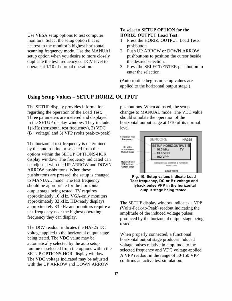
The SETUP display provides informationregarding the operation of the Load Test.Three parameters are metered and displayedin the SETUP display window. They include:1) kHz (horizontal test frequency), 2) VDC(B+ voltage) and 3) VPP (volts peak-to-peak).
The horizontal test frequency is determinedby the auto routine or selected from theoptions within the SETUP OPTIONS-HOR.display window. The frequency indicated canbe adjusted with the UP ARROW and DOWNARROW pushbuttons. When thesepushbuttons are pressed, the setup is changedto MANUAL mode. The test frequencyshould be appropriate for the horizontaloutput stage being tested. TV requiresapproximately 16 kHz, VGA-only monitorsapproximately 32 kHz, HD-ready displaysapproximately 33 kHz and monitors require atest frequency near the highest operatingfrequency they can display.
The DCV readout indicates the HA325 DCvoltage applied to the horizontal output stagebeing tested. The VDC value may beautomatically selected by the auto setuproutine or selected from the options within theSETUP OPTIONS-HOR. display window.The VDC voltage indicated may be adjustedwith the UP ARROW and DOWN ARROW
pushbuttons. When adjusted, the setupchanges to MANUAL mode. The VDC valueshould simulate the operation of thehorizontal output stage at 1/10 of its normallevel.
The SETUP display window indicates a VPP(Volts-Peak-to-Peak) readout indicating theamplitude of the induced voltage pulsesproduced by the horizontal output stage beingtested.
When properly connected, a functionalhorizontal output stage produces inducedvoltage pulses relative in amplitude to theselected frequency and VDC voltage applied.A VPP readout in the range of 50-150 VPPconfirms an active test simulation.
17
Fig. 10: Setup values indicate LoadTest frequency, DC or B+ voltage and
flyback pulse VPP in the horizontaloutput stage being tested.

A VPP reading that is 1/10 of the chassisnormal indicates a proper setup. Mosthorizontal output stages use bipolartransistors, in which the voltage pulsesproduced during normal operation range from800 to 1100 volts peak-to-peak. In the SETUPVALUES display window the VPP readoutshould read in the range of 80 to 110 VPP. AVPP reading of 100 VPP serves as a goodreference setting when the normal level isunknown.
Some horizontal output stages use MOSFETtransistors. Flyback pulses in these stagescommonly range from 500 to 800 VPP. Whentesting a MOSFET horizontal output stageestablish a VPP reading 1/10 or normal orbetween 50 and 80VPP. To manually adjustFrequency (kHz) and VDC:
1. Apply POWER & Press the HORIZ.OUTPUT Load Tests pushbutton.
2. Push the DOWN ARROW pushbutton toposition the cursor beside the MANUALselection.
3. Press the ENTER pushbutton. (kHz blinksawaiting adjustment)
4. Press Down Arrow or Up Arrowpushbuttons to increment the testfrequency (kHz).
5. Press the ENTER pushbutton. (Enters kHz-VDC blinks awaiting adjustment)
6. Press Down Arrow or Up Arrowpushbuttons to increment VDC value.
7. Press ENTER (Enters VDC – kHz blinksawaiting adjustment)Note: VPP should read 1/10 of chassisnormal – 100 VPP typical.
Performing the HORIZ. OUTPUT Load Test
In the TEST HORIZ. OUTPUT displaywindow, the HA325 simultaneously metersand displays three automatic measurements.The measurements reflect the operation of thehorizontal output stage being tested. The
measurements are used to determine whetherthe horizontal output stage is normal orcontains a defect. The three measurements aresummarized in Chart 2.
Load Test Display Readout Description of Test B+ Current ____ mA The current supplied by the Load Test B+ power supply to the horizontal output stage under test.
Efficiency ____ % EFF The percentage of the current input to the horizontaloutput stage at the beginning of the horizontal cyclethat is returned to the power supply at the end of
the cycle.
Pulse Time ____ µS The duration of the induced voltage pulseproduced by the horizontal output stage.
Chart 2: Description of the three measurements performed during the Load Test.
The three Load Test measurements accuratelyreflect the operation of the horizontal outputstage under test. The “mA” readout indicatesthe current being drawn by the horizontal
output stage from the Load Test DC powersupply. This current reflects the current drawnby the horizontal output stage from thechassis B+ power supply. In other words, this
18

is the power supply load current to thehorizontal output stage. Since the Load TestDC supply is approximately 1/10 of normalchassis B+ voltage, the “mA” readout isapproximately 1/10 of the normal chassispower supply load current. The “mA”readings typically range from 10 to 75 mA innormal operating horizontal output stages.When severe loading problems exist in thehorizontal output stage, the “mA” readingsrise significantly.
The “% EFF” readout measures whatpercentage of the input energy or current tothe output stage is returned to the B+ powersupply at the end of the horizontal cycle.Horizontal output stages are primarily tunedLC circuits with energy alternating betweenthe magnetic fields of the flyback and/or yokeand capacitance of the output stage. At theend of the horizontal cycle the magnetic fieldscollapse, returning stored energy back to thepower supply. Defects add power losses,greatly reducing the efficiency of thehorizontal output stage and the percentage ofenergy returned to the power supply.Efficiency readouts typically range from 50 to90% in normal horizontal output stages anddecrease dramatically in problem horizontaloutput stages.
The “µS” readout is an automaticmeasurement of the pulse duration or time of
the inductive voltage produced in thehorizontal output stage being tested. The LoadTest measures the time of the pulse from thestart of its rising edge to the end of its fallingedge.
The pulse time is determined by the stageinductance, retrace timing capacitor(s), yoke,and yoke series components. The “µS”readout provides an indication of the LCtiming of the horizontal output stage. Thetiming influences the flyback pulse amplitude,which determines the amount of yokedeflection and CRT high voltage.
To perform the HORIZ. OUTPUT LoadTest:
1. Apply POWER to the HA325, press theHORIZ OUTPUT pushbutton.
2. Select a SETUP OPTION using UP andDOWN ARROW keys.
3. Press the ENTER pushbuttonNote: In “MANUAL” select frequencyand VDC values and press theTESTS/SETUP pushbutton.
4. Read the “mA”, “µS”, and “% EFF”readouts in the LOAD TESTS displaywindow.
5. Compare readout results to typical ranges.Press and hold the ASSISTANCEpushbutton for helpful messages duringthe testing process.
Fig. 11: The Horiz. Output Load Test measurements include mA, % EFF and µS readings.
19

Interpreting Horiz. Output mA,% EFF and µS Readings:
The HA325 accompanies the Horiz. OutputLoad Test mA, % EFF and µS numericreadings with a “Good”, “?” or “Bad”indication. These are shown on the right sideof the display window. These indications areshown when the Load Test is active andflyback pulses in the range of 80-110 VPP arepresent in the horizontal output circuit beingtested.
The normal mA readout varies amonghorizontal outputs depending upon if the stageis a high voltage, deflection or combinationHV and deflection output. It also varies withthe size of the CRT as more horizontal yoke
current and HV is required from thehorizontal output stage. The mA readoutcommonly ranges from 10-75 mA.
The Good/?/Bad mA ranges are shown inChart 3. Readings from 5-35 mA areconsidered “Good” and readings over 76 mAare considered “Bad.” Readings from 36-75mA are considered “?” by the HA325. Thisrange of current is normal for some horizontaloutput stages but is excessive for others. AllHV-only horizontal outputs and those in a 13inch TV or monitor should be considered badif the Load Test current exceeds 35 mA.Horizontal Output stages with CRTsincreasing to 27 inch commonly range toabout 55 mA. Horizontal Output stages withlarger CRTs commonly range to 75 mA.
HORIZ. OUTPUT LOAD TEST GOOD/?/BAD mA, µS RANGESParameter Good ? Bad mA 5-35 mA 36-75 mA > 76 mA% EFF 55-100% 46-54% < 45%, 1%, 0%µS Based upon setup option and test frequency < 1%
Chart 3: Horiz. Output Load Test Good/?/Bad ranges.
Efficiency readings that range from 55-100%are considered “Good” by the HA325.Readings of 0-45% are considered “Bad” andindicate a likely setup frequency error or anexcessive power loss associated with thehorizontal output stage. Readings from 46 to54 are considered “?.” If a questionablereading is accompanied by a higher thannormal mA reading, a defect is likely. If thequestionable reading is accompanied by anormal mA reading the horizontal outputstage is likely good.
Flyback pulse times, indicated by the LoadTest µS readout, vary among displays. Thenormal µS range can be determined with thehorizontal blanking interval of the videosignal to be displayed and the display’s over-scan or under-scan characteristics. In multi-format monitors it is the video signal with theshortest horizontal blanking interval, typicallythe highest horizontal scanning frequency,that dictates the displays retrace time andtherefore the µS pulse time.
20

The HA325 defines a typical µS range, basedupon the video format’s horizontal blankinginterval and under vs. over-scan displaycharacteristic. The Good/?/Bad µS ranges for
the fixed frequency and VDC setup options ofthe HA325 are shown in Chart 4. TheGood/?/Bad µS ranges for the manual or autosetup options are shown in Chart 5.
HORIZ. OUTPUT LOAD TEST – µS Ranges Good/?/Bad (Setup Options)Preset: Good ? Bad TV: 11.0-13.9 µS 10.8-10.9, 14.0-14.9 µS 0.1-10.7, >14.9 µSHDTV 1080 3.7 - 6.0 µS 3.5 - 3.6, 6.1 - 6.3 µS 0.1 - 3.4, > 6.0 µSHDTV 720 3.7 - 6.0 µS 3.5 - 3.6, 6.1 - 6.3 µS 0.1 - 3.4, > 6.0 µSVESA 38 4.0 - 6.9 µS 3.7 - 3.9, 7.0 - 7.1 µS 0.1 - 3.7, > 7.1 µSVESA 48: 2.8 - 5.5 µS 3.5 - 3.7, 5.6 - 5.7 µS 0.1 - 3.5, > 5.7 µSVESA 64: 2.8 - 5.0 µS 2.6 - 2.7, 5.1 - 5.3 µS 0.1 - 2.5, > 5.3 µSVESA 75: 2.5 - 4.3 µS 2.2 - 2.4, 4.4 - 4.6 µS 0.1 - 2.1, > 4.6 µSVESA 88 2.0 - 3.4 µS 1.8 - 1.9, 3.5 - 3.6 µS 0.1 - 1.7, > 3.6 µS
Chart 4: Good/?/Bad µS ranges for setup options of the HA325.
HORIZ. OUTPUT LOAD TEST – µS Ranges Good/?/Bad (Manual & Auto Frequency)Man. Freq. Auto Good ? Bad 15-17.9 kHz 16 kHz 11.0-13.9 µS 10.8-10.9, 14.0-14.9 µS 0.1-10.7, >14.9 µS18 - 30 kHz 25 kHz 7.0-10.9 µS 6.5 - 6.9, 10.9-11.5 µS 0.1 - 6.4, >11.5 µS31 - 40 kHz 35 kHz 3.7 - 6.9 µS 3.5 - 3.6, 7.0 - 7.2 µS 0.1 - 3.4, > 7.2 µS41 - 49 kHz n/a 3.8 - 5.5 µS 3.6 - 3.7, 5.6 - 5.7 µS 0.1 - 3.7, > 5.7 µS50 - 59 kHz 60 kHz 3.2 - 5.0 µS 3.0 - 3.1, 5.1 - 5.2 µS 0.1 - 2.9, > 5.2 µS60 - 75 kHz 75 kHz 2.6 - 4.3 µS 2.4 - 2.5, 4.4 - 4.5 µS 0.1 - 2.3, > 4.5 µS76 - 95 kHz 85 kHz 2.0 - 3.4 µS 1.8 - 1.9, 3.5 - 3.6 µS 0.1 - 1.7, > 3.6 µS > 95 kHz 100 kHz 1.5 - 2.8 µS 1.3 - 1.4, 2.9 - 3.0 µS 0.1 - 1.2, > 3.0 µS
Chart 5: Good/?/Bad µS ranges for manual and auto setup options.
FLYBACK & IHVT LOAD TEST
The FLYBACK & IHVT Load Test analyzesflyback transformers and integrated highvoltage transformers to determine if they arefree of defects or if problems exist. TheFlyback & IHVT Load Test verifies if theflyback or IHVT is the cause of problemswhen the Horiz. Output Load Test indicates asevere horizontal output stage defect. TheFlyback & IHVT Load Test can also be usedto isolate AC Loading defects in the
horizontal output stage to the primary circuitcomponents or to the flyback & secondarycircuit loads.
This section familiarizes you with the Flyback& IHVT Load Test and explains how toproperly “setup” and perform the tests. Theapplications section of this manual showshow to use the FLYBACK & IHVT LoadTest to isolate AC loading problems.
21

Understanding the FLYBACK &IHVT Load Test
The Flyback & IHVT Load Test analyzesflyback transformers and integrated highvoltage transformers (IHVT) for defects usingthe HA325 Load Test circuitry. The primarywinding of the flyback or IHVT being testedis tuned with a timing capacitor to ground,internal to the HA325, forming a horizontaloutput stage. The HA325 switching transistorand horizontal drive generator simulate theoperation of this horizontal output stagecontaining the flyback or IHVT being testedin a manner similar to performing the Horiz.Output Load Test.
The HA325 simulates the operation of testcircuit containing the flyback or IHVT to betested at approximately 1/10 of the normalcurrent and voltages. The timing of thehorizontal output stage is determined by theinductance of the flyback or IHVT beingtested and typically varies from 10-18 µS
with TV flybacks and 5-10 µS with highfrequency monitor flybacks.
The HA325 applies a variable DC voltage orB+ to the primary of the flyback transformer.The HA325 internal frequency generator andswitching transistor energizes the flyback orIHVT producing AC currents. The frequencymay be selected automatically with the autosetup option, be preset to a specific frequencywith the TV or Hi-scan setup options or bemanually selected.
During the SETUP and TEST displaywindows, the Flyback & IHVT simulation isactive and the flyback or IHVT being testedproduces flyback pulses. The SETUPFLYBACK/IHVT display window showsthree readouts to help you determine if thesetup is accurately simulating a 1/10 voltageand current level. The TESTFLYBACK/IHVT display window shows theresults of three measurements, whichdetermine if the flyback or IHVT is good orcontains a defect.
Fig. 12: The Flyback & IHVT Load Test forms a horizontal output stagewith the IHVT being tested and simulates it operation at 1/10 of normal power.
22

Test Lead Connections -FLYBACK/IHVT Load Test
To perform the FLYBACK & IHVT LoadTest, you must connect the three coloredconnector clips of the LOAD & RINGERTEST LEAD to the proper flyback or IHVTpins before connecting the LOAD &RINGER TEST LEAD clips.
The FLYBACK & IHVT Load Test producescurrent and inductive voltage pulses. Becareful not to come into contact with theseenergized component points while performingthe Load test or when connecting ordisconnecting the test clips. Connect the testclips before entering an option from theSETUP OPTION display window. Push theFLBYACK & IHVT or POWER pushbuttonto remove voltage to the IHVT beforeremoving the test clips.
CAUTIONDo not come in contact with the flyback or IHVT pins, focus, anode, or G2 leadsduring the FLYBACK & IHVT Load Test.
The clips on the LOAD/RINGER TESTS LEAD are labeled and color-coded for easyidentification. Connect the leads to the flyback or IHVT as listed.
Clip Color Lead Label Description of Circuit Connection Point
Orange B+ Primary winding pin of flyback or IHVT where B+ voltage is input.
Yellow C or D Primary winding pin of flyback leading to Collector orDrain of the Horizontal Output Transformer
Black E or S Ground pin of the flyback or IHVT
Connect the black test clip to one of theground pins of the flyback transformer orIHVT. Connect the orange test clip to the B+voltage input pin to the flyback or IHVTprimary winding. Connect the yellow test clipto the other side of the primary. The primarypin leads to the collector or drain of thehorizontal output transistor.
Fig. 13: Setup for using the Flyback & IHVTLoad Test.
23

Selecting a Setup Option -FLYBACK/IHVT Load Test
When the FLYBACK & IHVT Load Testspushbutton is pressed and released, a list ofsetup options are displayed. The top line inthe digital display is titled SETUP OPTIONS-FLY. These setup options for the FLYBACK& IHVT Load Test provide ease inestablishing a test frequency and DC voltageto the IHVT or flyback to be tested. Select theoption that provides an appropriate frequencyto test the flyback or IHVT and a DC voltageto simulate operation at 1/10 of the normallevel, typically 100 VPP.
In the SETUP OPTIONS-FLY displaywindow a cursor block on the left side of thedisplay allows user selection of one of thesetup options. There are more setup options
available than can be viewed at one time onthe display. Pushing the UP ARROW andDOWN ARROW pushbuttons brings moreoptions into view. The arrow indicators aboveand/or below the cursor block on the displayscreen indicate more options are availablebelow and/or above the cursor that cannot becurrently shown on the display.
To select one of the setup options, positionthe cursor to the left of the desired setupoption and press the ENTER pushbutton. Thisbegins the auto setup routine or applies thetest frequency and voltages for the optionselected. If the MANUAL option is entered,the SETUP FLBYACK/IHVT displaywindow is displayed for adjustment of thefrequency and VDC values beginning at20kHz and 1 VDC.
SETUP OPTIONS (FLYBACK & IHVT) FREQUENCY VDC AUTO Automatic selected Automatic selected TV Fixed 20 kHz Fixed 12 VDCHIGH SCAN Fixed 30 kHz Fixed 8 VDCMANUAL Adjustable from 20 kHz Adjustable from 1V
Chart 6: Setup options for performing the HORIZ. OUTPUT Load Test.
The AUTO setup works well to quickly find asetup for testing most flybacks and IHVTs.Defects that dramatically change the timing ofthe generated flyback pulse may result ininappropriate setup values. Pushing theTEST/SETUP pushbutton following the autosetup routine displays the setup valuesestablished by the auto setup. Changing thevalues of the frequency or VDC values shownafter the AUTO setup defaults the setup toMANUAL mode.
Use the TV setup options for testingtelevision flyback and IHVTs. The frequencyand VDC is consistent with the majority ofTV horizontal output stages and providesreliable setup. Use the HI-SCAN setup optionfor testing flyback or IHVTs found in HD-
ready TVs, multi-media, computer monitorand high-resolution displays. Use theMANUAL setup option when you desire tochange the test frequency or DCV level tosimulate 1/10 of normal operation.
To select a setup option for the FLYBACK& IHVT Load Test:1. Press the FLYBACK & IHVT Load Tests
pushbutton.2. Push UP ARROW or DOWN ARROW
pushbuttons to position cursor besidedesired selection.
3. Press the ENTER pushbutton to enter theselection.(Auto routine begins or setup values areapplied to the flyback or IHVT.)
24
Using Setup Values - SETUPFLYBACK/IHVT
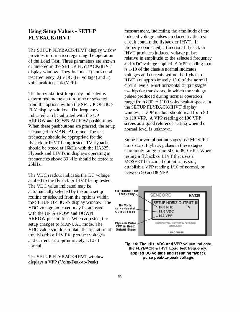
The SETUP FLYBACK/IHVT display widowprovides information regarding the operationof the Load Test. Three parameters are shownor metered in the SETUP FLYBACK/IHVTdisplay window. They include: 1) horizontaltest frequency, 2) VDC (B+ voltage) and 3)volts peak-to-peak (VPP).
The horizontal test frequency indicated isdetermined by the auto routine or selectedfrom the options within the SETUP OPTION-FLY display window. The frequencyindicated can be adjusted with the UPARROW and DOWN ARROW pushbuttons.When these pushbuttons are pressed, the setupis changed to MANUAL mode. The testfrequency should be appropriate for theflyback or IHVT being tested. TV flybacksshould be tested at 16kHz with the HA325.Flyback and IHVTs in displays operating atfrequencies above 30 kHz should be tested at25kHz.
The VDC readout indicates the DC voltageapplied to the flyback or IHVT being tested.The VDC value indicated may beautomatically selected by the auto setuproutine or selected from the options withinthe SETUP OPTIONS display window. TheVDC voltage indicated may be adjustedwith the UP ARROW and DOWNARROW pushbuttons. When adjusted, thesetup changes to MANUAL mode. TheVDC value should simulate the operation ofthe flyback or IHVT to produce voltagesand currents at approximately 1/10 ofnormal.
The SETUP FLYBACK/IHVT windowdisplays a VPP (Volts-Peak-to-Peak)
measurement, indicating the amplitude of theinduced voltage pulses produced by the testcircuit contain the flyback or IHVT. Ifproperly connected, a functional flyback orIHVT produces induced voltage pulsesrelative in amplitude to the selected frequencyand VDC voltage applied. A VPP reading thatis 1/10 of the chassis normal indicatesvoltages and currents within the flyback orIHVT are approximately 1/10 of the normalcircuit levels. Most horizontal output stagesuse bipolar transistors, in which the voltagepulses produced during normal operationrange from 800 to 1100 volts peak-to-peak. Inthe SETUP FLYBACK/IHVT displaywindow, a VPP readout should read from 80to 110 VPP. A VPP reading of 100 VPPserves as a good reference setting when thenormal level is unknown.
Some horizontal output stages use MOSFETtransistors. Flyback pulses in these stagescommonly range from 500 to 800 VPP. Whentesting a flyback or IHVT that uses aMOSFET horizontal output transistor,establish a VPP reading 1/10 of normal, orbetween 50 and 80VPP.
Fig. 14: The kHz, VDC and VPP values indicatethe FLYBACK & IHVT Load test frequency,applied DC voltage and resulting flyback
pulse peak-to-peak voltage.
25

Performing the FLYBACK & IHVTLoad Test
The FLYBACK & IHVT Load Testsimultaneously meters and displays the samethree automatic measurements as shown inthe HORIZ. OUTPUT Load Test. Themeasurements reflect the operation of theflyback or IHVT in the simulated horizontaloutput circuit. The measurements are used todetermine if the flyback or IHVT is normal orcontains a defect.
The three Load Test measurements accuratelyreflect the operation of the flyback or IHVTin the horizontal output test circuit. The “mA”readout indicates the current being drawn bythe flyback or IHVT from the HA325 DCpower supply. This is the power supply loadcurrent to the flyback or IHVT. The “mA”readings typically range from 3 - 15 mA witha good flyback or IHVT. The “mA” readingsrise significantly when defects exist with theflyback or IHVT.
The % EFF readout measures whatpercentage of the input energy or current tothe flyback or IHVT in the simulatedhorizontal output stage is returned to the B+power supply at the end of the horizontalcycle. Flyback or IHVT defects add powerlosses, greatly reducing the efficiency of thehorizontal output test circuit and thepercentage of energy returned to the powersupply. Efficiency readouts typically range
from 60 to 90% when the flyback or IHVTcontains no defects.
The “µS” readout is an automaticmeasurement of the pulse duration of theinductive voltage produced by the flyback orIHVT in the horizontal output test circuit. TheLoad Test measures the time of the pulsefrom the start of its rising edge to the end ofits falling edge. The pulse duration isdetermined by the inductance of the flybackor IHVT. Therefore, the resulting µS time willvary between flybacks or IHVTs. The “µS”timing will typically vary from 10-16 µS withTV flybacks and from 5-10 µS with highscanning frequency monitors.
To perform the FLYBACK & IHVT LoadTest:
1. Apply POWER to the HA325, press theFLYBACK & IHVT pushbutton.
2. Select an appropriate setup option usingthe UP ARROW and DOWN ARROWpushbuttons.
3. Press the ENTER pushbutton.Note: In MANUAL setup, select VDC andfrequency values and press theTEST/SETUP pushbutton.
4. Read the “mA”, “µS”, and “% EFF”readouts in the digital display.
5. Compare readout results to typical ranges.Press and hold ASSISTANCE pushbuttonfor helpful messages during the testingprocess.
26
Fig. 15: Threemeasurements
during theFlyback & IHVT
Load Test analyzeits operation.

Interpreting Flyback/IHVT mA,% EFF and µS Readings:
The HA325 accompanies the FLYBACK &IHVT Load Test mA, % EFF and µS numericreadings with a “Good”, “?” or “Bad”indication on the right side of the displaywindow. These indications are shown whenthe Load Test is active and flyback pulses inthe range of 80-110 VPP are present in thehorizontal output circuit being tested.
The Good/?/Bad mA ranges of the Flyback &IHVT Load Test are shown in Chart 7.Readings from 3-15 mA are considered“Good” and readings over 20 are considered“Bad.” Readings from 16-20 are considered“?” by the HA325. Most flyback transformerswith Load Test mA readings exceeding 15mA are defective. However, a few lessefficient flyback transformers or IHVTS havenormal Load Test currents ranging from 15-20 mA. Testing at a reduced test frequency
can also increase current readings into thequestionable range.
Efficiency readings that range from 60-100%are considered “Good” by the HA325.Readings of 0-49% are considered “Bad” andindicate a likely defect with the flybacktransformer or IHVT. Readings in the rangeof 50-59% are considered questionable. Theflyback or IHVT is likely defective if aquestionable % EFF reading is accompaniedby a higher than normal mA reading.
Readings from 6-15 µS are considered“Good” when performing the Flyback &IHVT Load Test. The µS reading or timing ofthe HA325 Load Test circuit will not agreewith the timing of the circuit in which theflyback or IHVT was removed. Therefore, theµS reading is not used to determine if theFlyback or IHVT is defective. However, if theµS reading is considerably different than the“Good” 6-15 µS range, a defect is likely.
Flyback & IHVT Good/?/Bad RangesTest Parameter Good ? Bad mA 3-15 mA 16-20 mA >20 mA% EFF 60-100% 50-60% <1-49%µS 6-15 µS 5.0-5.9, 15.1-15.9 µS 0.1-4.9 >15.9 µS
Chart 7: Good/?/Bad ranges for the Flyback & IHVT Load Test.
RINGER TESTS
The HA325 Ringer Tests are used to locate ashorted turn in a yoke, flyback, coil orswitching transformer. The Ringer Testchecks the coil's quality or “Q” and locatesshorted turns that cannot be detected withother troubleshooting tests. The testdynamically checks all the windings in ayoke, flyback, a non-iron core transformer orcoil for a shorted turn(s). A single shortedturn causes all of the other windings thatshare the common core to also ring bad.Therefore you need to ring only the primary
winding of a flyback or non-iron coretransformer.
Three Ringer Test options including 1) YokesAnd Flybacks, 2) Coils and 3) SwitchingTransformers are provided, allowing theHA325 to automatically check differentinductor types. In each case, connecting theRinger Test leads to the coil places acapacitor in parallel with the coil. The HA325applies energy to the cap/coil combinationand automatically ranges the capacitor value
27
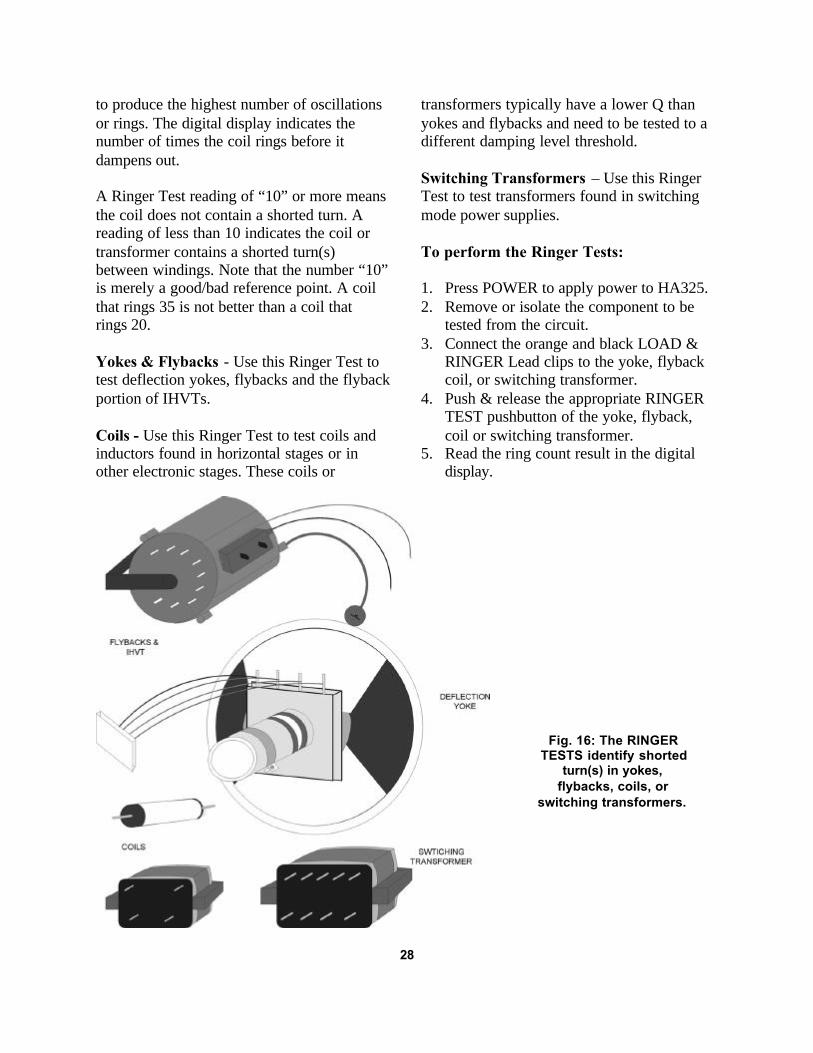
to produce the highest number of oscillationsor rings. The digital display indicates thenumber of times the coil rings before itdampens out.
A Ringer Test reading of “10” or more meansthe coil does not contain a shorted turn. Areading of less than 10 indicates the coil ortransformer contains a shorted turn(s)between windings. Note that the number “10”is merely a good/bad reference point. A coilthat rings 35 is not better than a coil thatrings 20.
Yokes & Flybacks - Use this Ringer Test totest deflection yokes, flybacks and the flybackportion of IHVTs.
Coils - Use this Ringer Test to test coils andinductors found in horizontal stages or inother electronic stages. These coils or
transformers typically have a lower Q thanyokes and flybacks and need to be tested to adifferent damping level threshold.
Switching Transformers – Use this RingerTest to test transformers found in switchingmode power supplies.
To perform the Ringer Tests:
1. Press POWER to apply power to HA325.2. Remove or isolate the component to be
tested from the circuit.3. Connect the orange and black LOAD &
RINGER Lead clips to the yoke, flybackcoil, or switching transformer.
4. Push & release the appropriate RINGERTEST pushbutton of the yoke, flyback,coil or switching transformer.
5. Read the ring count result in the digitaldisplay.
28
Fig. 16: The RINGERTESTS identify shorted
turn(s) in yokes,flybacks, coils, or
switching transformers.
APPLICATIONSINTRODUCTION
The applications section helps you understand horizontal stages. It includes examples of typicalapplications to provide you with an understanding of how to use and interpret the HA325analyzing tests. It further provides you with ideas on how to use the HA325 to take advantage ofits full potential.
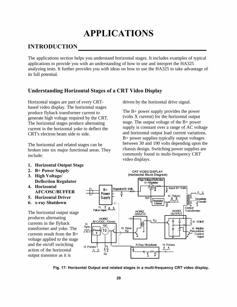
Understanding Horizontal Stages of a CRT Video Display
Horizontal stages are part of every CRT-based video display. The horizontal stagesproduce flyback transformer current togenerate high voltage required by the CRT.The horizontal stages produce alternatingcurrent in the horizontal yoke to deflect theCRT's electron beam side to side.
The horizontal and related stages can bebroken into six major functional areas. Theyinclude:
1. Horizontal Output Stage2. B+ Power Supply3. High Voltage/
Deflection Regulator4. Horizontal
AFC/OSC/BUFFER5. Horizontal Driver6. x-ray Shutdown
The horizontal output stageproduces alternatingcurrents in the flybacktransformer and yoke. Thecurrents result from the B+voltage applied to the stageand the on/off switchingaction of the horizontaloutput transistor as it is
driven by the horizontal drive signal.
The B+ power supply provides the power(volts X current) for the horizontal outputstage. The output voltage of the B+ powersupply is constant over a range of AC voltageand horizontal output load current variations.B+ power supplies typically output voltagesbetween 30 and 190 volts depending upon thechassis design. Switching power supplies arecommonly found in multi-frequency CRTvideo displays.
Fig. 17: Horizontal Output and related stages in a multi-frequency CRT video display.
29

The high voltage/deflection regulator variesthe B+ voltage to the horizontal output stageto keep the high voltage and/or deflectionconstant with changes in scanningfrequencies. The high voltage/deflectionregulator may be a linear regulator or a“buck” or “boost” switching type. The “buck”switching type is the most common. It uses aswitching MOSFET transistor driven with apulse width drive signal from a regulatorcontrol stage. The regulator control varies thedrive according to feedback from thehorizontal output stage to increase or decreasethe B+ voltage to the horizontal output stage.
The horizontal oscillator produces the drivesignal required for on/off switching of thehorizontal output transistor. The horizontaloscillator stage is commonly part of anintegrated circuit. The oscillator uses discretecomponents such as a crystal or resistor andcapacitor. Multi-frequency displayscommonly use resistors and capacitors thatcan be switched or varied to change theoscillator frequency. The oscillator is lockedto the frequency of the video's horizontal syncpulses and adjusted in phase to center thepicture on the CRT by an automatic frequencycontrol (AFC) stage. A buffer amplifier in the
IC shapes the oscillator signal into a square-wave output that is applied to the horizontaldriver stage.
The horizontal driver stage amplifies theweak horizontal drive waveform. Thehorizontal driver stage for a bipolar horizontaloutput transistor includes an amplifier with acurrent step-up transformer to produce theproper drive current. The horizontal driverstage for a MOSFET horizontal outputtransistor uses an amplifier to provide achanging voltage to the MOSFET's highimpedance gate.
All CRT-based video displays include over-voltage or x-ray shutdown protection. Thisstage disables the horizontal output stage toshutdown the chassis if the high voltageincreases to an unsafe level. The horizontaloutput stage is disabled by removing B+ orhorizontal drive either of which stops theoutput stage from producing high voltage.Causes of excessive high voltage andshutdown include too much B+ voltage to thehorizontal output stage, a horizontal outputstage timing problem, or a reduced horizontaldrive frequency.
30

Understanding Horizontal Troubleshooting Difficulties
Much of the difficulty in troubleshootinghorizontal related problems and symptoms ofa CRT video display can be understood bystudying figure 17. Each stage develops anoutput, based upon inputs or voltagesproduced by other stages. It is the interactionand inter-dependence of each horizontal stageon the other stages that make symptoms anddefects difficult to isolate.
To better understand this, consider thehorizontal output stage and B+ power supply.The B+ power supply outputs a normalvoltage when the current demand or load ofthe horizontal output stage is within a normalrange. An abnormal increase in current in theoutput stage can cause a decrease in theoutput B+ supply voltage. Also, gating pulsesfrom the horizontal output stage transformerare commonly used for switching or syncingof the B+ power supply. A lower than normalB+ voltage can be caused by defects in thesupply or horizontal output stage.
The interaction between the horizontal outputstage and the B+ power supply is mostapparent when the horizontal output stagedevelops severe timing or excessive currentdemands (power supply loading). The severeconditions place immediate high current stresson horizontal output transistors, highvoltage/deflection regulators and B+ powersupply components. These severe horizontaloutput stage problems can cause immediatedamage to replacement horizontal outputtransistors and power supply components, ifnot isolated before applying AC power.
The secondaries of the horizontal outputtransformer interact with the horizontal output
stage. Shorts in the secondary circuits causean abnormal increase in current in thehorizontal output stage and load the B+ powersupply input. These conditions are not evidentwith resistance tests in the horizontal outputstage.
In multi-frequency monitors, a high voltageand/or deflection regulator adjusts the B+voltage to the output transformer to producenormal high voltage and/or deflection.Feedback voltage pulses from the outputtransformer to the regulator control blockform a closed loop regulator. Defects in thecircuit loop cause improper operation of theoutput stage and high voltage/deflectionregulator. Since all the stages of the loop arealtered, it is difficult to isolate the problem tothe stage and component.The x-ray or high voltage shutdown circuitsclosely interact with the horizontal outputstage. The shutdown circuit detects excessivehigh voltage and immediately shuts down theoperation of the horizontal output stage byinterrupting horizontal drive or B+ voltage.Since conditions are momentary, conventionalvoltage measurements cannot be made toisolate the problem.
Voltage or gating pulses from the horizontaloutput transformer feed the horizontal AFC orphase detectors and may be used to power thehorizontal driver stages. Feedback from theoutput transformer to horizontal phase ordriver stages may cause problems with thehorizontal drive signal and output stageoperation. Once again, the closed circuit loopmakes troubleshooting difficult.
31

Guide To The HA325 Tests
The unique analyzing tests of the HA325provide effective troubleshooting capabilitiesto isolate horizontal and related chassissymptoms. The HA325 tests are performedwith the chassis power off and include theHORIZ. OUTPUT and FLYBACK & IHVT
Load Tests. The HA325 also provides aRinger Test optimized for testing yokes,flybacks, IHVTs, coils and switchingtransformers. A guideline as to when to useeach HA325 test is shown in Chart 8.
HA2500 test When to use What it tells you
HORIZ. OUTPUT Full AC cannot be applied: Output stage functions.LOAD TEST B+ supply dead or bad. Short/Load on B+ supply.
H.O.T heats or fails. Output stage pulse timing. B+ supply squeals, burns-up Output stage efficiency. components or blows fuses.
X-ray shutdown symptom.
FLYBACK & IHVT HORIZ. OUTPUT Load Test Flyback/IHVT functions.LOAD TEST is abnormal (High mA, low %). Flyback/IHVT mA load.
Flyback/IHVT efficiency.
(The FLYBACK & IHVT Load Test may be used in-circuit to isolate AC loading defects tohorizontal output stage primary components or flyback/IHVT and/or secondary components.)
FLYBACK & IHVT Flyback/IHVT has improper HV Flyback/IHVT secondary defect.EXTENDED TESTS focus, G2, or secondary output. IHVT multiplier defect.
IHVT focus/G2 divider defect.
RINGER TEST Load Tests is abnormal. Confirm if yoke, coil,Suspect flyback, yoke, or transformer is bad from
horizontal coil defect. shorted turn(s).
Chart 8: Guide to HA325 Horizontal Analyzing Tests.
Connecting the Load Tests LeadsWithout a Schematic
To connect the Load Test clips without theaid of a schematic diagram, first locate thehorizontal output transistor or transistors.There may be one or two horizontal outputstages. When two horizontal output stages areused, one produces high voltage while theother produces horizontal deflection.
A single horizontal output stage producesboth high voltage and deflection.Horizontal output transistor(s) are normallylocated near the flyback transformer or yokeconnector plug on the circuit board. Mosthorizontal output transistors are variations ofa TO-3P case style and are mounted to a largemetal heat sink. The circuit path of thecollector or drain should lead to a pin of theflyback, or yoke transformer or coil.
32

If you are unsure if the transistor is ahorizontal output type, use a semiconductorcross reference book to match the transistornumber and identify a replacement transistor.Check the uses specified for the replacementtransistor and the breakdown voltage ratingBVceo. Most horizontal output bipolartransistors have a rating greater than 1000volts (typically 1500V) and MOSFETtransistors greater than 800 volts (typically800 or 1000V).
Once you have identified thehorizontal output transistor(s),connect the yellow test clip to thecenter lead (collector or drain).Identify the ground for thehorizontal output circuitry.Horizontal ground typicallyconnects to the emitter or sourcelead of the horizontal outputtransistor directly, or through aparasitic inductor or small valueresistor. The ground circuit pathon the board typically has a largetrace size. It may also be recognized as thetrace on the circuit board that the negativelead of many polarized capacitors shares.
Some horizontal output transistor emitters areconnected to the driver transformer. Typicallythe base lead contains a resistor or diodeleading back to the driver transformer whilethe emitter lead does not. In this configurationthe Load Test black clip may be connected toeither the emitter of the output transistor orhorizontal ground.
To identify the B+ input to the horizontaloutput stage, trace the circuit path from thecollector or drain of the horizontal outputtransistor to the output transformer or coil.This is one side of the primary winding of theoutput transformer, typically the flyback, orcoil in the HV-only horizontal output stage.With an ohmmeter, identify pin or pins that
have continuity to the collector pin of thetransformer. Typically one or two pins maybe identified. The B+ input pin may beidentified on the circuit board for you. If not,the B+ input typically has an electrolyticcapacitor to ground with a coil or low valueresistor leading to the B+ power supply orregulator. A second transformer pin that mayhave continuity to the primary winding likelyhas a diode connected to it to develop avoltage for the CRT.
If you are unsure of the B+ input, you can usea trial and error method to identify the B+input using the Load Test. Select anappropriate preset option from the SETUPOPTIONS-HOR display window for thehorizontal output stage you are testing. In theTEST HORIZ.OUTPUT display window,alternately connect the B+ or orange test clipsto pins of the transformer which may be theB+ input while monitoring the Load Testresults. The connection which produces LoadTest readings that are normal or closest tonormal, is likely the proper B+ input.Improper connections will show high levelsof mA readouts, loading or short indications,unusual µS readings or other unusual testresults.
33
Fig. 18: With a few simple steps you can connectand perform the Load Tests without a schematic.

Understanding the Auto Setup -HORIZ. OUTPUT Load Test
The HA325 provides several options toquickly establish a horizontal test frequencyand DC voltage to the horizontal output stageto be load tested. These options are availablein the SETUP OPTIONS-HOR displaywindow. An AUTO option is also available asa setup option. This section familiarizes youwith the flowchart the HA325 uses toestablish an appropriate test frequency andDC voltage automatically for the horizontaloutput stage being load tested.
When the AUTO setup option is selected bypushing the ENTER pushbutton, the HA325begins the auto setup process. The processbegins by applying a switching frequency of25 kHz and slowly incrementing the DCvoltage. Initially the AUTO setup flowchartrelies on the horizontal output circuit beingload tested to begin producing flyback pulses,approaching 25VPP with only a few volts DCapplied. When the flyback pulses are sensed,the µS meter measures the duration of thepulses.
The duration ofthe flyback pulsesis the key todetermining asuitable testfrequency for theauto setup. TVsand CGA monitorshave flyback pulsedurationsexceeding 10µS.High definitionTV displays andVGA monitorshave flyback pulsedurations in therange of 4-7 µS.Higher resolutiondisplays haveshorter and shortedflyback pulsedurations.The HA325chooses a testfrequency, basedupon the pulsetime. Once the
34
Fig. 19: The auto setup flowchart for the Horiz. Output Load Test.

new test frequency is selected, based upon theµS reading, the DC voltage is increased untilthe VPP reading nears 100VPP. Uponreaching 100VPP, the auto setup is completeand the Load Test results are displayed.
As with any automated process, failure toachieve the required criteria in each flowchartblock results in an unsuccessful setup.Improper connections to the horizontal outputstage being tested or severe defects in thestage are the most common cause ofautomatic setup failures. The blocks in figure19 show the HA325 AUTO setup flowchart.If the auto setup routine fails, a brief messageindicating the reason is displayed. The HA325then returns to the SETUP OPTIONS displaywindow.
Interpreting the Load Test mAReadout
The Load Test “mA” reading is the amount ofB+ current drawn from the Load Test VDCpower supply by the horizontal output stagebeing tested. The mA reading reflects thehorizontal output stage current load on thechassis B+ power supply. Since the Load Testis performed near 1/10th the normal B+voltage of the chassis, the B+ currentdisplayed by the Load Test is approximately1/10 of the chassis normal.
A normal or typical range of Load Test mAreadings varies with high voltage-only,deflection-only or combination horizontaloutput stages. Typical mA ranges furtherdepend on the CRT size. Larger CRT sizesrequire increased yoke current and highvoltage, resulting in greater horizontal outputstage power demands.
A high voltage-only horizontal output stagetypically demands 10 to 40 watts of power to
produce normal high voltage. The powerdemand of the horizontal output stage isprovided by the B+ power supply (Volts XCurrent = Power). If the chassis B+ voltage is100 volts, the B+ supply delivers 400 mA tothe output stage to deliver the needed 40watts. If the HA325 Load Test was performedusing 10 volts B+ (1/10 of normal), the mAreadout should be near 40 mA. If anotherchassis requiring 40 watts uses a B+ voltageof 125 volts, the power supply current is325 mA, corresponding to a Load Test currentof 32 mA. A 70 volt B+ supply would needto output 570 mA for the same 40 watts.Considering a power range of 10 to 40 watts,a typical B+ voltage range, Load Test mAreadings in the range of 10 to 60 mA aretypical in a high voltage-only horizontaloutput stage. Although rare, slightly higherLoad Test mA readouts may be encountered ifthe output stage operates at B+ voltagesbelow 70 volts and/or has power demandsexceeding 40 watts.
Deflection-only and combination horizontaloutput stages require more power andsubsequently more B+ power supply current.See Chart 2. The added power demandincreases the normal mA readings during theLoad Test. Combination horizontal outputstages in TVs with CRT sizes less than 26inch or multi-frequency monitors with CRTsizes less than 16 inches, typically have LoadTest mA currents ranging from 10 to 50 mA.Deflection-only horizontal output stages,typically found in multi-frequency monitorswith larger CRT sizes, typically have LoadTest mA currents ranging from 10 to 70 mA.This range is also typical of combinationhorizontal output stages in TVs with CRTsizes exceeding 25 inches and multi-frequency monitors with CRT sizes exceeding15 inches.
35

Chart 9: The normal or typical Load Test mA ranges of horizontal output stages.
Load Test mA readings in the typical rangeindicate a normal current load on the B+power supply. Check the µS and % EFFreading to confirm that the horizontal outputstage has no other defects.
Load Test mA readings below 10 mA areunusually low. Readings below 10 mAusually indicate an invalid Load Test orimproper setup condition. An improper setupcan result from improper circuit clipconnections, unusually low B+ voltage,unusually high test frequency or an open inthe horizontal output circuit. Check for propercircuit connections and the Load Test SetupValues to confirm a proper B+ voltage andtest frequency is being applied.
Load Test mA readings greatly exceeding thetypical current range for the horizontal outputstage type and CRT size indicate a heavycurrent demand in the horizontal output stageor flyback secondary. The heavy currentdemand will likely load down the highvoltage or deflection regulator and B+ powersupply stressing components when ACvoltage is applied. Isolate the problem andconfirm normal Load Test results beforeapplying AC voltage.
Load Test mA readings that are slightly abovethe typical current range are questionable. Itmay be normal for a certain chassis to slightlyexceed the normal mA range if its B+ voltageis lower than the norm or its powerrequirements are slightly higher. Currentreadings exceeding the typical range mayindicate a subtle horizontal output stageproblem or result from using a slightly higherthan normal Load Test B+ voltage or lowerthan normal test frequency.
When a mA reading just above the typicalrange is encountered, check the VPP readingin the SETUP VALUES display window. AVDC voltage higher than the 1/10 levelcauses an increase in output stage powerdemand and load on the B+ supply. Reducethe VDC until the VPP is approximately 100VPP (bipolar output transistor) and 80VPP(MOSFET output transistor. This may reducethe mA reading into the typical range. Next,check the remaining Load Test µS and % EFFreadouts. If either or both tests indicateunusual readings, a horizontal output stagedefect is likely. If both tests indicate normal,the horizontal output stage does not have asevere defect and AC power may be appliedfor further testing.
36
Interpreting The Load Test% EFF Readout
The Load Test “% EFF” readout measureswhat percentage of the input energy or currentto the output stage is returned to the B+ powersupply at the end of the horizontal cycle.Horizontal output stages are primarily tunedLC circuits, which return a large share ofenergy back to the power supply at the end ofeach cycle. Defects add power losses, greatlyreducing the efficiency of the horizontaloutput stage and the percentage of energyreturned at the end of each cycle.
The Efficiency measurement is based uponthe ratio of two current measurements,reflecting the efficiency of the horizontaloutput stage under test. A gated conductioncurrent measurement is made of both theLoad Test horizontal output transistor and theLoad Test “mA” or B+ power supply current.The gated current measurement captures thehorizontal output transistor conductioncurrent representing the total input of energyto the inductors (coil, flyback and/or yoke) ofthe horizontal output stage. The “mA” or B+supply current represents the current neededto replenish the output stage to satisfy itscurrent demand each cycle. The supplycurrent represents the energy or currentconsumption of the output stage andtransformer secondaries.
The ratio of these currents represents whatpercentage of the input energy or current isreturned to the output stage during eachhorizontal cycle. Normal horizontal outputstages return a substantial amount of unusedenergy to the B+ supply at the end of eachhorizontal cycle. Defects cause the horizontaloutput stage to have increased losses, greatlyreducing the output stage efficiency and theratio between the Load Test currents.
At the beginning of the horizontal cycle, theLoad Test horizontal output transistorconducts, producing a current buildup in thehorizontal output stage's transformer or coil.The current buildup is the energy input to thehorizontal output stage being tested. The inputcurrent energizes the stage, producing amagnetic field in the transformer or coil.During the remainder of the horizontal cycle,current alternates in the stage, transferring theinput energy from a magnetic field to acapacitive charge and finally back to amagnetic field. At the end of the cycle theenergy remaining in the magnetic field isreturned to the power supply.
If all the input energy to the horizontal outputstage were returned at the end of the cycle, noB+ supply current would be needed after thefirst cycle. The B+ supply current would bezero, and some level of conduction currentwould exist in the output stage. Thehorizontal output stage would be 100%efficient. But, all horizontal output stageshave some inefficiencies or losses. Power isinduced into the flyback transformersecondaries and used to produce CRTcurrents and gating pulses to other stages.Other energy is dissipated in the inherentlosses of the components in the horizontaloutput stage. For this reason the % EFFreadout is always less than 100%.
The % EFF readout varies among horizontaloutput stages, depending on the level ofpower transfer to secondaries and thehorizontal output stage configuration. Highvoltage-only horizontal output stagestypically are 60-95% efficient. Deflection-only and combination horizontal output stagestypically range from 50-95% efficient.Overall, expect efficiency readings to behigher than 50% for the majority of horizontaloutput stages.
37

Occasionally, an efficiency reading slightlyless than 50% may be encountered. This canoccur from a design inefficiency in thehorizontal output stage or in one of itscomponents. If the mA readout is in a typicalrange, the efficiency is simply a reflection ofa circuit inefficiency. If the mA reading is
questionable or high, press the TEST/SETUPpushbutton and check the VPP and frequencysetup values. The frequency should be nearthe highest horizontal frequency capability ofa multi-frequency or multi-mode display. TheVPP should be 1/10 of the chassis normal orapproximately 100VPP for most displays.
Chart 10: Typical “% EFF” readout ranges of horizontal output stage configurations.
A % EFF readout in the typical rangeindicates the horizontal output stage andtransformer secondaries are exhibiting anormal range of energy losses and transfer.Efficiency readouts considerably below thetypical range for the horizontal output stageconfiguration indicate a substantial increase incircuit power losses or power transfer to asecondary. Low efficiency readouts usuallyaccompany high mA test results when severehorizontal output stage problems exist.
The “% EFF” test is especially useful whentesting multi-frequency monitors. An error insetting the Load Test B+ voltage and/or testfrequency may cause the “mA” readout to beabove the normal range. In these instances the“% EFF” readout provides an additionalanalysis of the horizontal output stage toindicate if excessive circuit losses orinefficiencies exist. If the % EFF is in anormal range, a higher than normal “mA”readout is likely a result of too much appliedB+ voltage for the test frequency chosen.
Note: The efficiency test is mostlyindependent of the applied Load Test B+voltage and frequency. Only extreme B+voltage or frequency settings causesubstantial changes in the “% EFF”Therefore, the efficiency readout can indicateoutput stage losses or defects that may bemissed due to improper Load Test B+ orFrequency settings. It can also helpdifferentiate questionable “mA” results whenyou are unsure of the proper Load Test B+voltage.
Interpreting The Load Test µSReadout
All horizontal output stages produce aninductive flyback voltage pulse, typically atthe collector or drain of the horizontal outputtransistor. The voltage pulse occurs duringhorizontal blanking time and coincides withthe yoke retrace period. The pulse timeduration is determined by the inductance orcapacitance of the flyback or coil primary,retrace timing capacitor(s), yoke, and yokeseries components.
38

The “µS” readout during the Load Testmeasures the pulse duration with the chassisoff. The measurement is triggered atapproximately the 5% levels of the voltagepulse for pulses exceeding 10 VPP. The “µS”readout closely duplicates the pulse time ofthe chassis horizontal output stage whenpowered to its full B+ voltage.
The pulse time is important for properoperation of the horizontal output stage. TheLC timing of the output stage determines theamplitude of the induced voltage pulse in theoutput stage. The amplitude of the pulsereflects the energy induced to the yoke toproduce deflection and energy induced intothe flyback transformer to produce highvoltage. The pulse time also reflects the timein which retrace must be performed and videoblanked.
The normal pulse time or µS reading variesbetween horizontal output stages dependingon the display's capabilities. The pulse timemust begin and end relative to the video'shorizontal blanking interval. If the picture isover-scanned, such as in NTSC television, thepulse duration is typically 0-30% greater thanthe approximately 11uS blanking interval.Since the video is over-scanned on the CRT,the voltage pulse begins just before the startof the horizontal interval and ends slightlyafter the horizontal interval. This producestypical µS pulse durations of 11 to 14 µS onNTSC-compatible television displays. HDTVis also over-scanned, resulting in a µS pulseduration slightly longer than the 3.77 µS(1080i) blanking interval.
On under-scanned video displays, the voltagepulse does not begin until the start of theblanking interval and ends before active videobegins at the end of the horizontal interval.This is because video blanking and retracecannot occur during active video visible onthe CRT edges. Therefore, the video'shorizontal blanking time serves as anapproximate maximum µS pulse time in thesedisplays. The minimum µS time in an under-scan display is typically not less than 70% ofthe blanking interval time. This producestypical µS pulse durations from 70-100% ofthe horizontal blanking time. This rangeapplies to deflection-only horizontal outputstages, combination horizontal output stageand most high voltage-only horizontal outputstages.
39
Fig. 20: Typical pulse µS times relate to thehorizontal blanking interval and overscan
or underscan characteristics of the display.
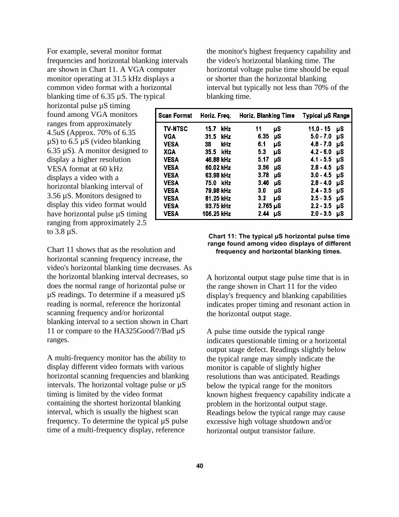
For example, several monitor formatfrequencies and horizontal blanking intervalsare shown in Chart 11. A VGA computermonitor operating at 31.5 kHz displays acommon video format with a horizontalblanking time of 6.35 µS. The typicalhorizontal pulse µS timingfound among VGA monitorsranges from approximately4.5uS (Approx. 70% of 6.35µS) to 6.5 µS (video blanking6.35 µS). A monitor designed todisplay a higher resolutionVESA format at 60 kHzdisplays a video with ahorizontal blanking interval of3.56 µS. Monitors designed todisplay this video format wouldhave horizontal pulse µS timingranging from approximately 2.5to 3.8 µS.
Chart 11 shows that as the resolution andhorizontal scanning frequency increase, thevideo's horizontal blanking time decreases. Asthe horizontal blanking interval decreases, sodoes the normal range of horizontal pulse orµS readings. To determine if a measured µSreading is normal, reference the horizontalscanning frequency and/or horizontalblanking interval to a section shown in Chart11 or compare to the HA325Good/?/Bad µSranges.
A multi-frequency monitor has the ability todisplay different video formats with varioushorizontal scanning frequencies and blankingintervals. The horizontal voltage pulse or µStiming is limited by the video formatcontaining the shortest horizontal blankinginterval, which is usually the highest scanfrequency. To determine the typical µS pulsetime of a multi-frequency display, reference
the monitor's highest frequency capability andthe video's horizontal blanking time. Thehorizontal voltage pulse time should be equalor shorter than the horizontal blankinginterval but typically not less than 70% of theblanking time.
Chart 11: The typical µS horizontal pulse timerange found among video displays of different
frequency and horizontal blanking times.
A horizontal output stage pulse time that is inthe range shown in Chart 11 for the videodisplay's frequency and blanking capabilitiesindicates proper timing and resonant action inthe horizontal output stage.
A pulse time outside the typical rangeindicates questionable timing or a horizontaloutput stage defect. Readings slightly belowthe typical range may simply indicate themonitor is capable of slightly higherresolutions than was anticipated. Readingsbelow the typical range for the monitorsknown highest frequency capability indicate aproblem in the horizontal output stage.Readings below the typical range may causeexcessive high voltage shutdown and/orhorizontal output transistor failure.
40

Troubleshooting High mA & Low% EFF Load Test Readouts
The Load Test Setup and the Load Test canbe used to isolate defects in the horizontaloutput stage. If the Load Test readingsindicate high current and/or low efficiencyand/or bad µS readings, a problem exists inthe horizontal output stage. You can use theLoad Test Setup and Load Test readouts tohelp isolate the defect. Chart 12 showscommon combinations of Load Test readoutsand possible causes.
Chart 12: Common Load Test combination ofreadouts and likely causes.
There are commonly three types of shorts orleakage problems that cause extra B+ supplycurrent (loading). The Load Test candetermine the type of short or leakage(loading) problem and help you isolate it. Thethree types include:
1. A low resistance path for direct current(DC short to ground) on the B+ supply.
2. A DC leakage (higher resistance short) onthe B+ supply.
3. An AC short or leakage path in thehorizontal output stage.
The Load Test mA and % EFF readouts canbe used to determine what type of loadingproblem exist and provide feedback while youisolate the defect. A readout of approximately200 mA with a “--- %” readout indicates alow resistance DC short to ground on theVDC or B+ power supply. The HA325accompanies this readout with a “DCSHORT” message. This is the maximumcurrent that can be produced by the Load TestVDC power supply. Before assuming a circuitshort, check the test lead connections to besure your have connected to the proper B+circuit point.
There are many possible DC short paths. ADC short or leakage path can be caused by aleaky filter capacitor, diode or regulatorcomponent in the chassis B+ path. Defectsmay also be from shorts or leakage paths inthe horizontal output stage or other stagesconnected to the B+ power supply path. Seefigure 21. To isolate a DC short or leakagepath, first open the B+ supply circuit pathback to the power supply and other circuitspowered by the B+ supply. Hook the “B+”(orange) test lead directly to the B+ side ofthe flyback transformer primary winding.Leave the Collector (yellow) lead open andcompare the Load Test mA readout to theearlier reading. A DC current greater than 10mA indicates a DC leakage or short in thehorizontal output stage.
The most likely cause of a DC short on theVDC or B+ supply is a shorted horizontaloutput transistor. Disconnect the orange testclip and remove the chassis horizontal outputtransistor. Connect the test clip and repeat theLoad Test, noting the Load Test mA reading.If the mA reading is “--- mA” or below 5 mAyou have confirmed that the horizontal outputtransistor is shorted.
Caution: The Load Test energizes the horizontal output circuit. Remove the orange test clip orreturn to the SETUP OPTION – HOR. display when unsoldering or testing components.
41

If opening the horizontal output transistordoes not remove the short, continue to openpossible short paths. The opened componentor current path that reduces the mA reading tonear zero identifies the short.
Note: The Horiz Output Load Test can beperformed with the horizontal outputtransistor and/or damper in or out of circuit.These components, if good, will not changethe mA, % or µS readouts.
Fig. 21: Possible DC short or leakage paths, which can load down the TV's B+ power supply.
Loading problems, which are not lowresistance DC shorts, produce high mAreadouts and low efficiency readouts. Thefirst step in isolating the loading problem is todetermine if added load current is caused byDC loading or by AC loading.
The Horiz. Output Load Test can be used toisolate DC loading from AC loading bydisconnecting the “Collector or Drain” yellowtest clip from the horizontal output stagebeing tested. Removing the yellow clip stopsthe switching action removing any alternatingsawtooth currents in the output stage and allpower transferred to the flyback secondarycircuits and shorted turns which may exist inthe flyback or yoke. With the yellow leadopened, the Load Test Setup VPP reads near 0and the % EFF and µS readouts show dashedlines.
With the yellow clip open, select a propersetup option or manually set the Load Test B+to approximately 1/10 of the chassis normalB+. The Load Test mA readout indicates thecurrent to circuits powered by the Load TestVDC power supply. This includes the
horizontal output stage and perhaps thehorizontal driver stage and others. Thesestages typically draw less than 5 mA of DCcurrent from the Load Test B+ supply withthe yellow clip open. If the current is muchhigher than this, suspect a DC short orleakage path on the B+ power supply.
Note: Some horizontal output stages use asmall DC current for horizontal yokecentering which may be seen during this DCcurrent test.
If the current readout is much higher than thetypical range for the horizontal output stagebeing tested, but is normal when the yellowclip is removed, the high current is a result ofa severe AC current load in the horizontaloutput stage. The current demand may becaused by shorted turns in the inductors of theoutput stage or yoke or caused by a short orleakage on any of the secondary circuits ofthe flyback. It is also possible for thehorizontal output transistor or damper diodeto be breaking down during the test.
42

The HA325 contains a diagnostic routine thatautomatically opens the yellow clip leadinternally, opening the Load Test switchedoutput during high current (high mA) loadingconditions. When the mA current exceeds 100mA the HA325 momentarily opens drive andtests for existing DC current. If the currentexists with the drive opened, the current is DCcurrent and “DC LOAD” or “DC SHORT” isshown in the display.
Fig. 22: Possible AC shorts or leakage pathsin a horizontal output stage.
An effective method of isolating AC loadingsymptoms is to use the HA325 FLYBACK &IHVT Load Test in-circuit. See the Flyback &IHVT Load Test Application section of thismanual.
Troubleshooting Unusual µSReadouts
If the Load Test µS readout is outside thetypical range, or fluctuating by several µS, atiming problem in the horizontal output stageis indicated. If the Load Test also shows highmA and low % EFF readouts, ignore theunusual µS readout and isolate the excessiveloading problem first. Most loading problemscause the µS readout to decrease or fluctuate.There are commonly three types of problemsin the horizontal output flyback circuits,which will be evident on the µS readout.
1. A“---- µS” readout: Dashed lines in theµS readout indicate that the flyback pulsesnormally produced during the Horiz.Output Load Test are not present. Confirmthat the Load Test lead connections andLoad Test Setup parameters are proper. Itis likely that the Load Test Setup VPPalso reads “---VPP”. An improper leadconnection or an open circuit path fromB+ through the flyback primary to groundis likely. You can use an ohmmeter toisolate the open.
2. Stable µS readout above or below thetypical range: A steady µS readoutoutside the normal range indicates a valuechange in one of the critical timingcomponents in the horizontal output stage.If the µS readout is above the typicalrange, an open yoke current path and itsseries components are likely suspects. Ifthe µS readout is below the typical rangeand the mA reading is normal, check thedisplay’s frequency and resolutioncapabilities. Check the retrace timingcapacitors for reduced value.
A reduced µS readout is common inhorizontal output stages with a shortedflyback turn or shorts on the flybacksecondary circuits. These faultseffectively decrease the transformer orinductance value, causing the µS readoutto fall to the bottom of or below thetypical normal range. Shorted flybackturns and secondary loading problemscause higher than normal Load Test mAreadings and low % EFF readings.
3. µS readouts fluctuating by several µS:Readings that are changing values byseveral µS indicate that the waveshape ofthe flyback pulse is abnormal. Thewaveshape may have multiple flyback
43

pulses per cycle or abnormal pulse shapeor ringing. Severe output stage problemsor loading problems in the flybacksecondaries are likely causes. High mAand low % EFF Load Test resultscommonly accompany fluctuatingreadings.
When troubleshooting timing problemsand unusual µS readouts, it is sometimeshelpful to use an oscilloscope to view thepulse at the collector or drain of thehorizontal output transistor. Testhorizontal output stage components, yokeand its series components, flyback andflyback secondary circuits to isolate theproblem and correct the timing.
Understanding IHVT Failures
Integrated high voltage transformers are acomplex component or module. They containa transformer with multiple secondary
windings, a high voltage multiplier sectionand a focus/screen resistive voltage divider. Ifany of these sections fail, the IHVT must bereplaced.
The complexity of the IHVT results inmultiple failure modes and various displaysymptoms. Any of these failures requires thatthe IHVT be replaced. The possible IHVTfailure modes are listed below.
1. Shorted adjacent turn(s) in a primary or asecondary winding.
2. Short or leakage between a primary andan isolated secondary winding.
3. Short or leakage between a secondary andanother isolated secondary winding.
4. Open turn in a primary or secondarywinding.
5. Defect in the high voltage multipliersection.
6. Open or increased resistance in thefocus/screen voltage divider.
Fig. 23: An IHVT can fail in 6 different ways.
44
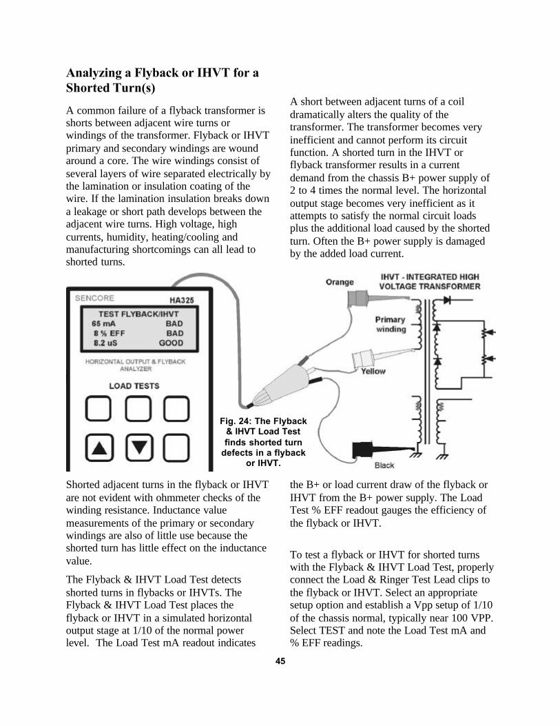
Analyzing a Flyback or IHVT for aShorted Turn(s)
A common failure of a flyback transformer isshorts between adjacent wire turns orwindings of the transformer. Flyback or IHVTprimary and secondary windings are woundaround a core. The wire windings consist ofseveral layers of wire separated electrically bythe lamination or insulation coating of thewire. If the lamination insulation breaks downa leakage or short path develops between theadjacent wire turns. High voltage, highcurrents, humidity, heating/cooling andmanufacturing shortcomings can all lead toshorted turns.
A short between adjacent turns of a coildramatically alters the quality of thetransformer. The transformer becomes veryinefficient and cannot perform its circuitfunction. A shorted turn in the IHVT orflyback transformer results in a currentdemand from the chassis B+ power supply of2 to 4 times the normal level. The horizontaloutput stage becomes very inefficient as itattempts to satisfy the normal circuit loadsplus the additional load caused by the shortedturn. Often the B+ power supply is damagedby the added load current.
Shorted adjacent turns in the flyback or IHVTare not evident with ohmmeter checks of thewinding resistance. Inductance valuemeasurements of the primary or secondarywindings are also of little use because theshorted turn has little effect on the inductancevalue.
The Flyback & IHVT Load Test detectsshorted turns in flybacks or IHVTs. TheFlyback & IHVT Load Test places theflyback or IHVT in a simulated horizontaloutput stage at 1/10 of the normal powerlevel. The Load Test mA readout indicates
the B+ or load current draw of the flyback orIHVT from the B+ power supply. The LoadTest % EFF readout gauges the efficiency ofthe flyback or IHVT.
To test a flyback or IHVT for shorted turnswith the Flyback & IHVT Load Test, properlyconnect the Load & Ringer Test Lead clips tothe flyback or IHVT. Select an appropriatesetup option and establish a Vpp setup of 1/10of the chassis normal, typically near 100 VPP.Select TEST and note the Load Test mA and% EFF readings.
45
Fig. 24: The Flyback& IHVT Load Testfinds shorted turn
defects in a flybackor IHVT.

Good flybacks or IHVTs typically draw 3-20mA of current and have efficiencies over55%. If the flyback or IHVT has Load Testmeasurements in this range, it does not have ashorted turn. If the chassis exhibits horizontaloutput problems, check the flyback or IHVTfor other failures as explained in this sectionof the manual.
A shorted turn(s) typically causes the currentto increase to over 30 mA and the % EFF tofall below 50%. Because of the severe natureof a shorted turn defect, it is not uncommonfor the current to increase above 50 mA andthe % EFF to be below 10%.
To test a flyback or IHVT for shortedturns:1. Properly connect the Load & Ringer Test
Lead clips to the flyback or IHVT.2. Apply POWER to the HA325; press the
FLYBACK & IHVT pushbutton.3. Select an appropriate setup option using
the up and down arrow pushbuttons.4. Press the ENTER pushbutton. Press
TEST/SETUP to confirm setup near100 VPP.
5. Press TEST/SETUP to read the “mA” and“% EFF” readouts in the digital display.
Analyzing a Flyback or IHVT forPrimary to Secondary Shorts
A flyback transformer or IHVT may developa short between turns of the flyback windingto a turn of a secondary winding. This defectcauses an increase in DC current from the B+power supply to flow through a secondarywinding to ground.
The Flyback & IHVT Load Test detectsshorts from the primary winding to isolatedsecondary windings. These defects are shownby an increase in the mA reading and adecrease in the % EFF reading. Shorts fromprimary to secondary are indicated by a LoadTest mA reading near 200 mA, accompaniedby a “DC SHORT” readout. DC leakagebetween the primary and secondary windingsranging from 50-150 mA with the Flyback &IHVT Load Test will be accompanied by a“DC LOAD” readout.
To test the flyback or IHVT for a primary to asecondary winding short or leakage, properlyconnect the Load & Ringer Test lead clips tothe flyback or IHVT. Select an appropriatesetup option and establish a Vpp setup of 1/10of the chassis normal, typically near 100 VPP.Select TEST and note the Load Test mA and% EFF readings.
Good flybacks or IHVTs typically draw 3-20mA of current and have efficiencies over55%. If the flyback or IHVT has Load Testmeasurements in this range, it does not have ashort between primary and a secondary.
A typical flyback or IHVT has multiplesecondary windings that are electricallyisolated from each other. To check forleakage from the primary to each of theisolated secondary windings, remove theblack clip lead and move it to one of the pinsof each isolated secondary winding. Checkthe Load Test mA and % EFF readings as theblack lead is connected to each isolatedsecondary. The mA and % EFF readingsshould remain in the good range. An increasein the mA reading or a mA reading that isaccompanied by a “DC LOAD” or a “DCSHORT” readout indicates a short or leakagefrom the primary to secondary.
46

Note: The primary winding of the flyback orIHVT may have a tap. Connecting the blackclip to this tap would result in a high mA and“DC SHORT” readout. This is normal.
To test a flyback or IHVT for primary tosecondary shorts:
1. Properly connect the Load & Ringer TestLead clips to the flyback or IHVT.
2. Apply POWER to the HA325; press theFLYBACK & IHVT pushbutton.
3. Select an appropriate setup option usingthe up and down arrow pushbuttons.
4. Press ENTER pushbutton.5. Read the “mA” and “% EFF” readouts.6. Move the black clip to a pin on each of
the isolated flyback secondaries whilechecking the Load Test mA and % EFFreadouts.
Analyzing the IHVT’s HV MultiplierSection
The HA325 Flyback & IHVT Load Test,combined with a high impedance DCV meter,provides additional analyzing capabilities orextended testing of an IHVT. An IHVTcontains a HV multiplier section, consistingof multiple secondary windings cascaded withHV diodes and capacitor filtering. Thewindings multiply and output the HV DCpotential needed by the CRT anode. The HVpotential exists at the HV anode lead withrespect to the flyback HV ground return. ThisHV return or HV ground pin may also becalled the aquadag ground.
An open in any of the HV section windings oran open HV diode causes little or no HVoutput. Minor defects in this section mayreduce the output HV to a fraction of normal.With these defects, the horizontal output stageworks normally and the Horiz. Output LoadTest shows normal operation, but the HVoutput is low or missing.
The Flyback & IHVT Load Test and a highimpedance DCV meter can be used to analyzethe output HV. Since the Flyback & IHVTLoad Test operates the IHVT atapproximately 1/10 of the normal powerlevel, the output HV produced during the testis approximately 1/10 of normal.
Proper voltage measurement of HV requiresthe use of a high impedance DC voltmeter.The typical input impedance DCV meter (10-15 megohms) loads the HV output, reducingthe metered voltage. Proper measurement ofHV can be achieved by increasing the inputimpedance of the DC meter to 100 megohmsor more.
The Sencore TP212 is a X10 multiplier probethat increases the DC input impedance of a 15megohm DC meter to 150 megohms. Themultiplier probe divides the voltage by 10,causing the DC meter to read 1/10 of thevoltage present at the probe tip. Use theSencore TP212 with the DC meters onSencore analyzers such as the Sencore VA62,TVA92, HA2500, SC3100 etc.
47
Fig. 25: Move the black clip to eachisolated secondary to test for high mA
primary to secondary leakage or shorts.

The Sencore DVM models DVM500 andDVM501 have a 10 megohm inputimpedance. Using a Sencore TP212 willreduce the normal 1/10 output DC voltage tothe meter by approximately 30%. These lowervoltages will complicate test interpretation. AX10 multiplier probe for a 10 megohmimpedance meter is available from ProbeMaster to extend the input impedance to 100megohms. (See www.probemaster.com)
To test the HV multiplier section of an IHVT,connect and set up the HA325 to perform theFlyback & IHVT Load Test. Establish asetup to produce a VPP that is approximately1/10 of the chassis normal VPP. Use 100 VPPif you are uncertain of the chassis normalflyback pulse amplitude (VPP). The LoadTest mA, % EFF and µS readings should bein the Good or ? range. If the Load Testmeasurements indicate a shorted turn, openprimary, or short from primary to secondary,the IHVT is defective and no IHVT multipliertesting is necessary.
With proper setup and Load Testmeasurements confirmed, connect the DCmeter ground to the HV ground return pin ofthe IHVT. Connect the X10 multiplier probeto the DC meter probe. Set the DVM to the
DCV function and probe the HV anode leadof the IHVT.
The voltage measured on the DC meter is theHV output of the IHVT. This voltage isreduced by a factor of 100 compared to theactual output voltage of the IHVT in thechassis; 1/10 by the Load Test and 1/10 by themultiplier probe of the DC meter. Multiplythe DC measured on the DVM by 100 fordirect comparison to the HV required by theCRT or reference in the schematic. Forexample, an IHVT that produces 26 kV in achassis may measure in the range of 240-280VDC, depending on the accuracy of the 1/10level and Load Test frequency used. If theVDC measured is near the 1/100 level, theHV multiplier section is functioningnormally.
If the high impedance DC meter reads a lowerthan normal 1/100 high voltage level, adefective multiplier section is likely. Checkconnections of the Flyback & IHVT LoadTest to the primary winding of the IHVT.Switching the orange clip and yellow clipalters the current polarity of the primary,greatly reducing the HV output, with littleeffect on the HA325 Load Test results.
Fig. 26: The Flyback & IHVT Load Test and high impedance DCVmeter can detect failures in the IHVT’s HV multiplier.
48

To Test the HV Multiplier Section of anIHVT:1. Properly Connect the Load & Ringer Test
Lead clips to the IHVT.2. Apply Power to HA325. Select Flyback &
IHVT Load Test.3. Select an appropriate setup option. Press
ENTER.4. Perform TEST FLYBACK/IHVT and
note mA, % EFF, µS readings.5. Press SETUP and manually adjust for
1/10 chassis VPP (Typically 100 VPP)6. Connect DC meter ground to the HV
ground return of the IHVT.7. Connect X10 multiplier probe to DC
meter. Probe HV anode lead output ofIHVT.
8. Read DC volts. Multiply DC volts by 100and compare to the expected chassis HV.
A missing or low DC voltage (IHVT HVoutput) indicates a defective IHVT multipliersection.
Analyzing the IHVT’s Focus &Screen Divider Section
Most IHVTs contain a section that taps highvoltage from the high voltage windings. Thehigh voltage is applied to a high resistancevoltage divider network to limit the currentflow. The network is connected to the HVground return pin of the IHVT, often calledthe CRT or aquadag ground return. Thevoltage divider resistor are commonly tappedto supply variable output voltages at levelsrequired by the CRT for focus and G2(screen) grid operation.
The high value resistors used in the dividercommonly open, increase in resistance, orbecome intermittent, causing a decrease in thefocus or screen output voltages. When this
occurs, the CRT goes dark and/or the focuscontrol cannot be turned far enough toachieve good focus. There may also be someinteraction between controls and outputvoltages. Since a weak electron gun can alsocause these symptoms, you should confirmproper electron gun low and high levelemission currents with a CRT tester, such asthe Sencore CR7000.
The Flyback & IHVT Load Test and a highimpedance DCV meter can be used to analyzethe output voltages of the focus and screenresistive divider. Since the Flyback & IHVTLoad Test operates the IHVT atapproximately 1/10 of the normal powerlevel, the output HV produced during the testis approximately 1/10 of normal.
Proper voltage measurement of focus andscreen voltages requires the use of a highimpedance DC voltmeter. The typical inputimpedance DCV meter (10-15 megohm)loads the HV output, reducing the meteredvoltage. Accurate measurement of focus andscreen voltages requires increasing the inputimpedance of the DC meter to 100 megohmsor more. Use a X10 multiplier probe such asthe Sencore TP212 for DC meters with a 15megohm input impedance.
To test the focus/screen divider section of anIHVT, connect and set up the HA325 toperform the Flyback & IHVT Load Test.Establish a setup to produce a VPP that isapproximately 1/10 of the chassis normalVPP. Use 100 VPP if you are uncertain of thechassis normal flyback pulse amplitude(VPP). The Load Test mA, % EFF and µSreadings should be in the Good or ? range.If the Load Test measurements indicate ashorted turn, open primary, or short fromprimary to secondary, the IHVT is defectiveand no IHVT multiplier testing is necessary.
49

With proper setup and Load Testmeasurements confirmed, connect the DCmeter ground to the HV ground return pin ofthe IHVT. Connect the HV multiplier probeto the DC meter probe. Set the DVM to theDCV function and probe the focus and screenvoltage outputs of the IHVT. These aretypically red and white wires that lead to theCRT circuit board. Other HV dividers withtaps are sometimes used for feedback to HVregulators, HV shutdown circuits etc. Youmay also test the DC voltage on these pins.You may vary the focus control(s) or G2(screen) control and observe the change involtage range provided by the adjustment.
The voltage measured on the DC meter is thefocus, G2, or tapped high voltage output ofthe IHVT. These voltages should beapproximately 1/100 of the actual outputvoltages of the IHVT in the chassis undernormal operation. The DC voltage on themeter is reduced 1/10 by the Load Test and1/10 by the multiplier probe. Multiply the DCmeasured on the DVM by 100 for directcomparison to the focus, screen, or tappedvoltages required by the CRT or referenced inthe schematic. For example, an IHVT thatproduces a range of 6-8 kV for focus in thechassis may measure in the range of 55-85VDC, depending on the accuracy of the 1/10level and Load Test frequency used. If theVDC measured provides the proper range or1/100 level, the focus and screen dividersection is functioning normally.
If the high impedance DC meter reads a lowerthan normal 1/100 voltage level as the controlis varied, exhibits a jumpy output voltage asthe control is varied, or has interactionbetween controls, a defective focus/screendivider is likely. Check connections of theFlyback & IHVT Load Test clips to the
primary winding of the IHVT. Switching theorange clip and yellow clip alters the currentpolarity of the primary, greatly reducing thefocus and screen output voltage with littleeffect on the HA325 Load Test results.
To test the IHVT’s focus & screen divideroutput voltages:
1. Properly Connect Load & Ringer TestLead clips to the IHVT.
2. Apply Power to HA325. Select Flyback &IHVT Load Test.
3. Select an appropriate setup option. PressENTER.
4. Perform TEST FLYBACK/IHVT andnote mA, % EFF, µS readings.
5. Press SETUP and manually adjust forchassis 1/10 VPP (Typically 100 VPP)
6. Connect DC meter ground to the IHVTHV ground return.
7. Connect a X10 Multiplier probe to the DCmeter. Probe the focus and G2 (Screen)outputs of IHVT.
8. Read meter DC volts. Multiply DC voltsby 100 and compare to the expectedchassis HV.
9. Vary the focus and G2 controls and testfor normal voltage ranges.
The G2 or Screen voltage is sensitive to theimpedance level of the DC meter. Its actualoutput DC voltage in a chassis is largelydetermined by G2 current drawn from theIHVT by the CRT. Testing with a highimpedance DC meter commonly produceshigher than expected output DC voltages.Higher than expected voltages that can bevaried through a voltage range indicate anormal screen output voltage and good screenvoltage divider.
50

Testing An IHVT for HV Multiplierto Secondary Shorts
An IHVT may fail because a secondarywinding develops leakage or a short toanother secondary winding. Secondarywindings are typically insulated from eachother by the lamination of the wire that makesup each winding. However, these wires arewound on top of each other around theflyback core. A breakdown of the laminationcauses leakage current or a short to developbetween formerly isolated windings. Shortsfrom a winding in the HV multiplier sectionto another secondary winding are commondue to high voltage potentials.
Shorts between an HV winding and anisolated secondary winding of the IHVT placehigh voltage potentials on the isolatedsecondary winding(s) with respect to the highvoltage ground. These high voltage potentialscommonly cause arcing on the circuit boardor burn out components on these secondaries,as they are not designed to withstand thesehigher voltage potentials. The Flyback &IHVT Load Test combined with a highimpedance DC voltmeter can be used to testfor shorts between the high voltage sectionand other isolated secondary windings.
To detect HV winding to secondaryshorts/leakage connect the Flyback & IHVTLoad Test to the IHVT. Set up the Load Testfor 1/10 of the normal flyback pulseamplitude, typically around 100 VPP. Use aDC voltmeter with a high impedancemultiplier probe to increase the inputimpedance of the DC meter to 10 megohm orgreater. The multiplier probe reduces the
voltage that is measured by the DC meter by10.
Note: The Sencore TP212 increases Sencore15 megohm input impedance meters to 150megohms. Multiply DC voltages measured by10.
With the Flyback & IHVT Load Test set for100 VPP, you can identify shorts or leakageto these normally isolated secondaries bymeasuring for high voltage potentials on thesewindings. Connect the ground of the highimpedance DC meter to the HV aquadagground. Measure the focus and/or screenvoltage to be sure you have connected and setup the HA325 properly and the DC meter isproperly measuring high voltage potentials.
Probe the secondary windings with themultiplier probe and note readings on the DCmeter. DC voltage readings should be low ornear zero. It is common for a high inputimpedance DC meter to read some randombut lower voltage readings. Random but lowvoltage readings indicate no shorts or leakagefrom the HV section to the primary winding.Probe other isolated secondaries to confirmthat no high voltage potential exists withrespect to HV ground.
DC voltage measurements that are near orequal to DC voltages measured at the HVanode, focus, and G2 (screen) outputs of theIHVT indicate high voltage potentials leakingto the isolated secondary.
51

To Test an IHVT for HV multiplier to secondary shorts/leakage:
1. Properly connect Load & Ringer TestLead clips to the IHVT.
2. Apply Power to HA325. Select Flyback &IHVT Load Test.
3. Select an appropriate setup option. PressENTER.
4. Perform FLYBACK/IHVT TEST andnote mA, % EFF, µS readings.
5. Press SETUP and manually adjust forchassis 1/10 VPP (Typically 100 VPP)
6. Connect the DC meter ground to theIHVT HV ground return.
7. Connect a X10 multiplier probe to the DCmeter. Probe the focus and G2 (Screen)outputs of the IHVT.
8. Probe isolated secondary pins of theIHVT and note DCV readings.
Fig. 27: The Flyback & IHVT Load Test and high impedance DC meter candetect leakage or shorts from the HV multiplier to the secondary.
Troubleshooting Horiz. OutputStage AC Loading Defects
The Horiz. Output Load Test analyzes thehorizontal output stage for loading or timingdefects. A loading defect typically results inhigh mA readings and low % EFF readings.Readings may be accompanied by “ACLOAD” or “AC SHORT” display indicatorswhen the current exceeds 100 mA and 150mA respectively.
When a defect is indicated by the Horiz.Output Load Test, a problem could exist inthe horizontal output stage components,
flyback, or flyback secondary circuitry.Isolating the defective circuit area reducestroubleshooting time, especially for ACloading defects that are not evident withohmmeter tests.
The FLYBACK & IHVT Load Test canisolate AC loading defects to the horizontaloutput stage or primary components or to theflyback & its secondary load circuitry. Theprimary circuitry includes the yoke and itscurrent path, timing components, and anywidth/pincushion components. The flybackand secondaries includes the IHVT/flyback,secondary circuits, CRT, HV blocks, etc.
52

The Flyback & IHVT Load Test effectivelysubstitutes the horizontal output stagecircuitry or primary components of theflyback. During the Flyback & IHVT LoadTest, a timing capacitor tunes the primary ofthe flyback or IHVT. The setup processestablishes an operating horizontal outputstage with the flyback or IHVT primary,resulting in flyback pulses approximately 1/10of normal or typically near 100 VPP.
This unique ability makes it possible to easilyisolate AC loading defects to the primarycircuitry/components or to the IHVT andsecondaries. Once the AC loading problem isisolated further tests can pinpoint the loadingdefect.
Isolating AC loading defects with theFLYBACK & IHVT Load Test requiresopening the circuit path connecting theflyback primary winding to the horizontaloutput circuitry/components. Typically youcan unsolder the primary pin of the flybackisolating it from the circuit board and tracesleading to the collector of the horizontaloutput transistor, timing capacitors, yoke etc.Occasionally a tap on the primary maycontain yoke or timing circuitry/components.Be sure to open other primary winding pinsthat may contain timing capacitors or primarycomponents.
With the horizontal output stage circuitryisolated from the flyback primary, connect theFLYBACK & IHVT Load Test clips. Theblack clip lead connects to ground, orangeclip lead to the B+ input of the flybackprimary, and yellow clip to the primary pinwhich is unsoldered/isolated from the circuitboard. Perform the Flyback & IHVT LoadTest and note the mA, % EFF and µSreadings with a typical 100 VPP setup. Toconfirm that the primary circuitry is opened,move the yellow clip to the collector of thehorizontal output transistor and comparemeasurement readings. The same load test
readings indicate the flyback pin is notcompletely unsoldered or isolated.
With the primary circuitry isolated from thetest, the Flyback & IHVT Load Testmeasurements indicate the condition of theflyback and secondary circuitry. A normalrange of mA, % EFF and µS indicates a goodflyback and secondaries, concluding aprimary component defect. High mA and low% EFF readings indicate an AC Loadingdefect associated with the IHVT or asecondary load.
You can further isolate high mA and low% EFF readings caused by the IHVT orsecondary loads. Open secondary circuit pathsand repeat the Flyback & IHVT load test,noting changes to the readings. For example,open connections to a HV block in projectionsystems, HV anode leads, remove CRT boardfrom CRT, open scan diodes etc. A defectiveload and associated circuitry is indicatedwhen the Load Test readings dramaticallydrop to normal levels. Abnormal Load Testreadings with most or all secondary loadsopen indicate a likely IHVT defect. Removethe IHVT completely from the chassis andconfirm with the Flyback & IHVT Load Test.
With the horizontal output primary circuitryisolated, good Flyback & IHVT Load Testreadouts indicate a defect associated with theprimary circuitry/components. Connect theprimary circuitry to the flyback/IHVTprimary and repeat the Horiz. Output LoadTest as you open the horizontal outputtransistor, damper diode, and yoke plug.Remember to disconnect the orange clip leadas you open components. A component thatgreatly reduces the mA reading is the likelycause of the loading. If the mA dropsdramatically with the yoke plug opened, usethe Ringer test to check the horizontal yokewinding for a shorted turn. Use a capacitoranalyzer, such as the Sencore LC103 toanalyze the yoke S-shaping capacitor(s).
53

To isolate AC loading defects – Flyback & IHVT Load Test:
1. Unsolder the IHVT primary pin, openingthe circuit path to horizontal outputcomponents.
2. Connect Load & Ringer Test clips.3. Apply Power to HA325. Select Flyback &
IHVT Load Test.4. Select the appropriate setup option. Set up
for approx. 100 VPP.5. Perform TEST FLYBACK/IHVT and
note mA, % EFF, µS readings.
Note: Confirm open primary circuitry bymoving the yellow clip to the collector of thehorizontal output transistor and notingdifferent readings. Same readings indicate theprimary circuitry is not opened.
High mA and low % EFF indicateFlyback/IHVT or secondary load defect.Good mA and % EFF indicate a primarycomponent defect.
Fig. 28: With the primary circuitry isolated from the test, theFlyback & IHVT Load Test measurements indicate the
Condition of the flyback and secondary circuitry.
54

MAINTENANCEIntroduction
The HA325 is designed for long term reliability. However, with a high percentage of portableuse anticipated, along with the rigors of transport and multiple battery charge/discharge cycles,several key components of the HA325 are designed for easy replacement. This section covershow to replace the battery pack, Load Test switching transistor and Load/Ringer test lead.It further covers how to update the unit's operating software, should a factory update becomeavailable.
Replacing components requires opening the HA325 case enclosure to reveal the internal circuitboards and components. Remove the HA325 from the padded cover if it is being used. The caseis held together by four case screws which are located on the back of the instrument, near each ofthe four corners. A small Philips screwdriver is required for removal. Place the instrument on abench or table covered with a soft cloth or padded surface. Remove the screws, placing them tothe side. Be sure to note which screws are on the top and which are on the bottom, as they aredifferent lengths. Be sure to use the longer screws near the top end of the HA325 during re-assembly. SEE CAUTION BELOW
--------------------------------------CAUTION------------------------------------------------------There are two lengths of screws. The two longer screws are used near the top of the instrument andthe two shorter screws at the bottom. Using the longer screws at the bottom can result in damage tothe case, as the longer screw length is excessive for the bottom locations.------------------------------------------------------------------------------------------------------------------
Place the instrument on its back and gentlylift the front side of the instrument up,separating it from the back. Hinge the frontportion of the instrument open and gentlyplace the front side flat on the padded surface,beside the case back. This reveals the insidecircuitry and components of the HA325.
To open the HA325 case enclosure:1. Place on front on padded bench surface.2. Remove the four rear screws.3. Place on back on padded bench surface4. Gently lift front side, separating it from
the back.5. Hinge front side open, placing it face
down on the padded bench surface.
Replacing the Internal Battery Pack
When the battery no longer holds a charge orprovides adequate use time, it can be easily
replaced. A replacement battery of the sametype and voltage is available from the SencoreService Parts department (Sencore #17A49).Replace only with a battery supplied bySencore.
To replace the battery pack, follow theinstructions to open the HA325 caseenclosure. The battery is located near thebottom of the instrument. The battery isconnected to the circuit board with aremovable connector. The battery is held inplace by the case covers, circuit boards andmetal edging.
When replacing the battery, be sure the unit ispowered off. Unplug the battery connectorfrom the circuit board and gently lift thebattery from its compartment. Install the newbattery by reversing the process.
55
To replace the battery pack:
1. Be sure unit is powered OFF2. Unplug battery connector from the circuit
board.3. Remove battery pack from its
compartment.4. Install new battery pack.5. Assemble case enclosure.
Replacing the Internal Load TestSwitching Transistor
The main output transistor used by the HA325Load Test is installed into a socket so that thetransistor can be easily removed and replaced.While this transistor is fuse protected, leavingthe Load Test leads connected to a livedisplay chassis or encountering a largeflyback pulse amplitude or B+ charge maycause it to short. A replacement transistor isavailable from the Sencore ServiceDepartment.
Note: The most likely failure of the Load Testoutput transistor is a short. You can test for ashorted Load Test transistor by connecting a1000 ohm resistor between the yellow andorange test clips of the HA325. The black clipis not used for this simple check. Select theHoriz. Output Load Test and select the “TV16 kHz” setup function. Normally in thisconfiguration, the Load Test readoutindicates 6 – 7 mA and approximately 30-32µS. If you obtain these readings, the LoadTest is functioning normally and thetransistor is good. A reading of 12-14 mAindicates a shorted Load Test outputtransistor.
The Load Test switching output transistor isQ9. It is located just behind the Load Testfuse on the back panel circuit board. Thetransistor may be removed by carefullyremoving the screw holding the transistor to
its heat sink. Remove the transistor from thecircuit board socket. Obtain a replacementtransistor for installation and reverse theprocess to install the new transistor.
The Load Test output transistor is an N-channel MOSFET transistor, numberMTP6N60 (Sencore #19G230). You canobtain a replacement from the SencoreService Parts Department. Do not use ageneral replacement, as it will alter themeasurement accuracy of the Load Test mAand % EFF measurements.
To Replace the Load Test SwitchingTransistor:
1. Follow the procedure to open the caseenclosure.
2. Locate Q9, a 6N60 socketed transistor.3. Remove the screw holding the transistor
to its heat sink.4. Remove the transistor from the socket.5. Replace the transistor with an identical
replacement.6. Reassemble the case enclosure.
Replacing the Load & Ringer TestLead
The Load & Ringer Test Lead is designed foreasy repair. The clips and other parts may bepurchased from the Service Department. Thetest lead cable is a durable cable that has beencycle tested at the factory and should providemany years of service. However, should itbecome damaged or frayed, the complete testlead can be removed and replaced withoutreturning the HA325 to the factory. Thecomplete Load & Ringer Test Lead Assembly(Part #39G799) may be ordered from theSencore service parts department.
56
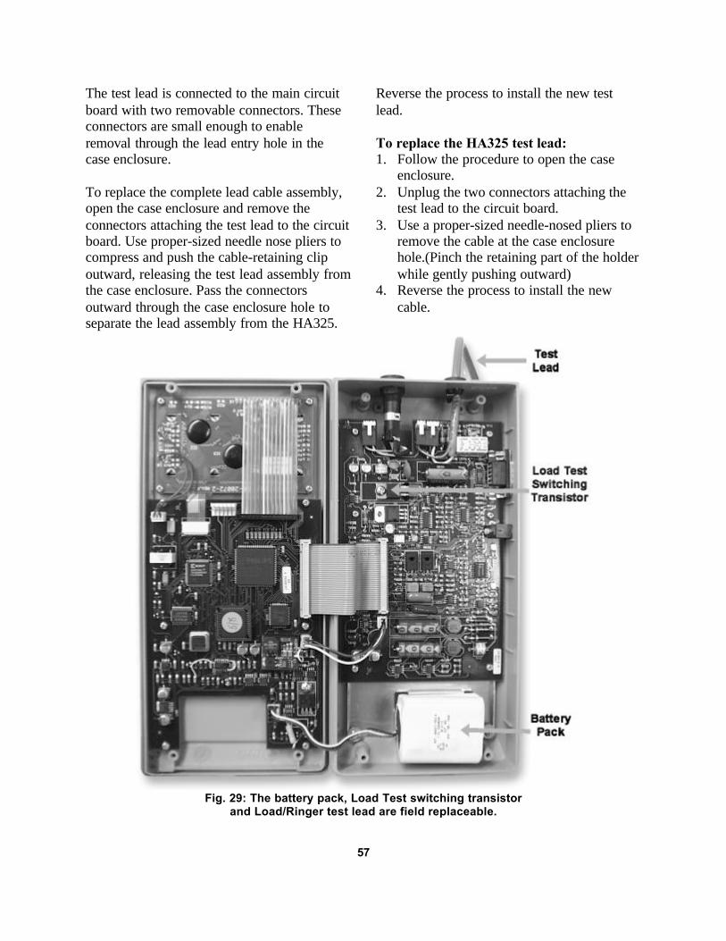
The test lead is connected to the main circuitboard with two removable connectors. Theseconnectors are small enough to enableremoval through the lead entry hole in thecase enclosure.
To replace the complete lead cable assembly,open the case enclosure and remove theconnectors attaching the test lead to the circuitboard. Use proper-sized needle nose pliers tocompress and push the cable-retaining clipoutward, releasing the test lead assembly fromthe case enclosure. Pass the connectorsoutward through the case enclosure hole toseparate the lead assembly from the HA325.
Reverse the process to install the new testlead.
To replace the HA325 test lead:1. Follow the procedure to open the case
enclosure.2. Unplug the two connectors attaching the
test lead to the circuit board.3. Use a proper-sized needle-nosed pliers to
remove the cable at the case enclosurehole.(Pinch the retaining part of the holderwhile gently pushing outward)
4. Reverse the process to install the newcable.
Fig. 29: The battery pack, Load Test switching transistorand Load/Ringer test lead are field replaceable.
57

Updating the HA325 OperatingFirmware
The HA325 includes a communications portfor interface to a computer. The port enablesthe HA325 operating software to be updated,using a computer running a communicationsprogram, should an upgrade in the softwareprogram become available from the factory. Aterminal communications program, such asHyperTerminal supplied with Windows 95,98 and WinNT4.0, Terminal, supplied withWin3.1, or any other terminal emulationprogram can be used to transmit the upgradefile to the HA325 RS232 port.
Connect an RS232 null modem cable from thecomputer serial port of the to the HA325RS232 Interface Port. Apply power to theHA325, using the supplied ACAdapter/Charger. Open the communicationsprogram to be used and establish acommunications link using the followingsettings.
Communications Settings:Baud: 9600Data Bits: 8Parity: NoneStop Bits: 1Flow Control: Hardware(Set to echo typed characters locally)
To upgrade unit firmware:
1. Connect null-modem cable (Sencore#39G523) from HA325 to Computerserial port.
2. Apply Power to the HA325. The PA273Power Adapter/Charger should beconnected.
3. Type ERASE and press <ENTER> on thecomputer keyboard. (HA325 Displaygoes blank)
4. The message “ARE YOU SURE? Y/N” isdisplayed. Type Y
5. The current firmware is erased followedby “READY FOR DATA” message.
6. Click on Transfer – Send Text File7. Change Files of Type to show All Files
(*.*)8. Navigate to the file HA325.hex and click
Open.9. Firmware update begins followed by three
beeps and “SUCCESS” message whencomplete.
10. Remove the null-modem cable.
The firmware loading time varies withdifferent computers and software. In mostcases, the firmware will be loaded in less than10 minutes.
58
Fig. 30: The HA325 operating softwarecan be updated with factory updates,using a computer connected to the
HA325 communications port.
WARRANTY & SERVICE INFORMATIONWARRANTYYour Sencore instrument has been built to the highest quality standards in the industry. Each unit hasbeen tested, aged under power for at least 24 hours, then every function and range was re-tested to insureit met all published specifications after aging. Your instrument is fully protected with a 1 year warrantyand Sencore's exclusive 100% Made Right Lifetime Guarantee in the unlikely event that a defect wasmissed. Details are covered in a separate document included with your instrument.
SERVICEThe Sencore Factory Service Department provides all in and out-of-warranty service and complete re-calibration services for Sencore instruments. No local service centers are authorized to repair Sencoreinstruments. Factory service assures you of the highest quality work, the latest circuit improvements andthe fastest turnaround time possible. Most service repairs are completed within 72 hours of receipt.
Re-packing For ShipmentSave the original shipping carton and packing material for reuse should you ever need to ship yourSencore instrument or return it to the Sencore factory for repair. If the original materials are unavailableor unfit for reuse, repack the HA325 according to the following guidelines.
1. Use a corrugated cardboard shipping container with adequate test strength and dimensions of at least10” X 17” X 20” (HWD).
2. Please call the Sencore Service Department and obtain a Return Verification Authorization number(RUA). Enclose the following information: Owners address, billing information, purchase order (ifapplicable), name and phone number of contact person, description of problem and reason for return.
3. Enclose the unit inside a plastic bag to protect its finish and prevent foreign material from gettinginside.
4. Cushion the unit equally on all sides with a minimum of 3 inches of padding material. Pack thepadding tightly enough to prevent the unit from shifting during shipment.
5. Seal all seams on the container with strapping tape.
6. Send the packed unit to the address listed below (we recommend shipping via United Parcel Service).
A separate schematic and parts list is available should you wish to repair your own instrument. Parts maybe ordered directly from the Service Department. Any parts not shown in the parts list may be ordered bydescription.
We reserve the right to examine defective components before an in-warranty replacement is issued.
SENCORE FACTORY SERVICE3200 Sencore DriveSioux Falls, SD. 57107Toll Free: 1-800-SencoreFAX 605-335-6379www.Sencore.com
Fill in for your records:Purchase Date: ____________ Serial Number:____________ Run Number:___________
Note: Please refer to the run number if is necessary to call the Sencore Factory Service Department. Therun number may be updated when the unit is serviced.

3200 Sencore DriveSioux Falls, SD 57107Call 1-800-SENCORE (736-2673) Innovatively designedwww.sencore.com with your time in mind.
Form 7151 Printed in U.S.A.