
SR5 Serial Protocol - Slot Techslot-tech.com/interesting_stuff/money controls/TSP121...‚cctalk...
50
SR5i ccTalk Protocol Manual TSP121 Issue 2.3 May 2005 This document is the copyright of Money Controls Ltd and may not be reproduced in part or in total by any means, electronic or otherwise, without the written permission of Money Controls Ltd. Money Controls Ltd does not accept liability for any errors or omissions contained within this document. Money Controls Ltd shall not incur any penalties arising out of the adherence to, interpretation of, or reliance on, this standard. Money Controls Ltd will provide full support for this product when used as described within this document. Use in applications not covered or outside the scope of this document may not be supported. Money Controls Ltd. reserves the right to amend, improve or change the product referred to within this document or the document itself at any time. Money Controls 2005. All rights reserved. SR5i Serial Protocol - Issue 2.3
Transcript of SR5 Serial Protocol - Slot Techslot-tech.com/interesting_stuff/money controls/TSP121...‚cctalk...
SR5i ccTalk Protocol Manual TSP121 Issue 2.3 � May 2005
This document is the copyright of Money Controls Ltd and may not be reproduced in part or in total by any means,electronic or otherwise, without the written permission of Money Controls Ltd. Money Controls Ltd does not acceptliability for any errors or omissions contained within this document. Money Controls Ltd shall not incur any penaltiesarising out of the adherence to, interpretation of, or reliance on, this standard. Money Controls Ltd will provide fullsupport for this product when used as described within this document. Use in applications not covered or outside thescope of this document may not be supported. Money Controls Ltd. reserves the right to amend, improve or changethe product referred to within this document or the document itself at any time.
Money Controls 2005. All rights reserved.
SR5i Serial Protocol-
Issue 2.3

SR5i ccTalk Protocol Manual TSP121 Issue 2.3 � May 2005
Money Controls 2005. All rights reserved.Page 2 of 50
Revision History
Issue Date Comments1.0 12-12-02 Draft release2.0 27-06-03 Updated for beta release
07-08-03 Added parallel override pin details for reference2.1 05-04-03 �Teach and Run� token select position is 6 or 122.2 12-01-05 New section : �On the Fly� Routing2.3 18-05-05 TSP number added and released.

SR5i ccTalk Protocol Manual TSP121 Issue 2.3 � May 2005
Money Controls 2005. All rights reserved.Page 3 of 50
Contents
1. DOCUMENTATION........................................................................................................................................ 5
2. INTRODUCTION............................................................................................................................................. 5
3. PRODUCT CAPABILITY............................................................................................................................... 5
4. ENCRYPTION AND SECURITY................................................................................................................... 6
5. PROTOCOL DESCRIPTOR........................................................................................................................... 6
6. DEVICE ADDRESS.......................................................................................................................................... 6
7. ELECTRICAL CONNECTIONS.................................................................................................................... 7
8. QUICK START................................................................................................................................................. 7
9. CREDIT POLLING.......................................................................................................................................... 9
9.1 CREDIT POLL TIMEOUT.................................................................................................................................. 9
10. COIN INHIBITS ............................................................................................................................................. 9
10.1 INDIVIDUAL COIN INHIBITS.......................................................................................................................... 910.2 MASTER INHIBIT ........................................................................................................................................ 1010.3 INHIBITS VERSUS SERIAL CREDIT CODE VERSUS COIN POSITION............................................................... 11
11. SORTER OPERATION ............................................................................................................................... 11
11.1 SORTER : WORKED EXAMPLE .................................................................................................................... 1211.2 �ON THE FLY� ROUTING............................................................................................................................. 13
12. DCE RUNDOWN & TOKENS.................................................................................................................... 13
12.1 TOKEN MODE SELECTION ........................................................................................................................... 1512.1.1. Industry-standard mode .................................................................................................................... 1512.1.2. DCE mode with DCE rundown plugged in ....................................................................................... 1512.1.3. DCE mode without using DCE rundown .......................................................................................... 15
13. TEACHING COINS AND TOKENS .......................................................................................................... 15
14. MECHTOOL................................................................................................................................................. 17
14.1 OPERATING NOTES .................................................................................................................................... 1814.1.1. Token Selection ................................................................................................................................. 1814.1.2. Token Teach ...................................................................................................................................... 1814.1.3. Address Selection .............................................................................................................................. 1814.1.4. EEPROM route programming .......................................................................................................... 1814.1.5. Routing Replication........................................................................................................................... 1914.1.6. Power-up Diagnostics....................................................................................................................... 1914.1.7. Solenoid Pulsing ............................................................................................................................... 1914.1.8. Encryption Key Recovery .................................................................................................................. 19
15. KEY TIMING PARAMETERS................................................................................................................... 19
16. TYPICAL COMMAND RESPONSE TIMES............................................................................................ 20
17. DEBUGGING : NO REPLY TO ANY COMMAND ?.............................................................................. 20
17.1 POWER....................................................................................................................................................... 2017.2 COMMS DATA FORMAT.............................................................................................................................. 2017.3 ADDRESS ................................................................................................................................................... 2117.4 DATA VOLTAGES & TIMING ...................................................................................................................... 2117.5 COMMAND HEADER................................................................................................................................... 2117.6 CHECKSUM ................................................................................................................................................ 22

SR5i ccTalk Protocol Manual TSP121 Issue 2.3 � May 2005
Money Controls 2005. All rights reserved.Page 4 of 50
17.7 TX LOOP-BACK ......................................................................................................................................... 2217.8 ENCRYPTION.............................................................................................................................................. 22
18. COMMAND LIST ........................................................................................................................................ 23
19. EVENT CODE TABLE................................................................................................................................ 30
19.1 EVENT CODE NOTES .................................................................................................................................. 31
20. FAULT CODE TABLE ................................................................................................................................ 32
21. REMOTE COIN PROGRAMMING .......................................................................................................... 34
21.1 INTRODUCTION .......................................................................................................................................... 3421.2 DATA FORMAT........................................................................................................................................... 35
21.2.1. Sub-Header 255 - Begin packet upload ............................................................................................ 3521.2.2. Sub-Header 254 - Upload packet data.............................................................................................. 3521.2.3. Sub-Header 253 - End packet upload & program ............................................................................ 3521.2.4. Sub-Header 249 - Remove coin signature......................................................................................... 3521.2.5. Sub-Header 248 - Request extended coin id ..................................................................................... 3521.2.6. Sub-Header 247 - Calculate ROM secure signature......................................................................... 3521.2.7. Sub-Header 245 - Remove all coin signatures .................................................................................. 3521.2.8. Sub-Header 244 - Request currency code......................................................................................... 3521.2.9. Sub-Header 243 - Request coin issue................................................................................................ 36
21.3 PROGRAMMING PROCEDURE...................................................................................................................... 3621.3.1. The �.bin� file..................................................................................................................................... 3621.3.2. The �.nnn� file .................................................................................................................................... 3721.3.3. Erasing Coins.................................................................................................................................... 3721.3.3.1. Erased Coin Identifiers ............................................................................................................. 3821.3.4. Individual Coin Filenames................................................................................................................ 3821.3.5. DOS Stub........................................................................................................................................... 38
21.4 EXTRA FILES.............................................................................................................................................. 3821.4.1. Extra File Programming ................................................................................................................... 39
21.5 TYPICAL REPROGRAMMING TIMES ............................................................................................................ 3921.6 COIN IDENTIFIERS...................................................................................................................................... 3921.7 CURRENCY CODE....................................................................................................................................... 3921.8 COIN ISSUES............................................................................................................................................... 4021.9 REMOTE PROGRAMMING ERROR CODE TABLE .......................................................................................... 41
22. FIRMWARE UPGRADING ........................................................................................................................ 42
22.1 FLASH CONNECTOR ................................................................................................................................... 42
23. APPENDIX A : MESSAGING EXAMPLES.............................................................................................. 43
23.1 INITIALISATION.......................................................................................................................................... 4323.2 PRE-ACCEPTANCE...................................................................................................................................... 4423.3 CREDIT POLLING........................................................................................................................................ 4423.4 REMOTE COIN PROGRAMMING .................................................................................................................. 46
24. APPENDIX B : PRODUCT DIFFERENCES ............................................................................................ 47
24.1 COMMAND DIFFERENCES........................................................................................................................... 4724.2 OTHER DIFFERENCES................................................................................................................................. 47
24.2.1. Token Selection ................................................................................................................................. 4824.3 TIMING DIFFERENCES ................................................................................................................................ 48
25. APPENDIX C : EXAMPLE ROM CHECKSUM TABLE ....................................................................... 49
26. APPENDIX D : SOFTWARE ISSUES ....................................................................................................... 50

SR5i ccTalk Protocol Manual TSP121 Issue 2.3 � May 2005
Money Controls 2005. All rights reserved.Page 5 of 50
1. Documentation
In order to write a host machine interface to the SR5i coin acceptor, the following additionaldocuments will need to be read.
�cctalk Serial Communication Protocol - Generic Specification - Issue 4.2�
The latest issue of this document in pdf format is available from the cctalk web site at�www.cctalk.org
The following document is only required if encryption is used.
�cctalk Serial Protocol - Encryption Standard - Version 1.1�
This document is available from the Technical Support Department at Money Controls andcontains details of the encryption algorithm which is a factory-configuration option on cctalkcoin acceptors. For security reasons this document cannot be emailed to you and will only besent after certain checks have been conducted.Email : [email protected]
2. Introduction
The SR5i is the latest in a range of 5 inch coin acceptors and follows on from SR5R, SR5 andC435S. The (i)ntelligent range of acceptors offer unparalleled performance through the use of anexpert system and rule-based decision making, combined with neural networks for precision,remote coin programming - without having to insert any coins.
The SR5i coin acceptor can operate entirely in serial mode with all conventional parallel controland status functions implemented in the cctalk serial protocol. This protocol is now a globalstandard in the money transaction industry.
This document contains details of operation in serial mode only. It is intended to be read by asoftware engineer wishing to interface a SR5i from a PC or embedded system.
3. Product Capability
SR5i has memory to store 16 different coin types and 6 token groups including a �teach and run�token. The teach and run token does not require a coin specification - it is programmed byinserting a small number of the tokens. If tokens are enabled then the chosen token replaces 1 or2 of the programmed coins.
Each coin has a unique serial credit code 1 to 16.
Any combination of 16 coins may be enabled or disabled through software.
Each accepted coin can be routed to 1 of 8 sorter paths if the appropriate hardware modules arefitted. Path overrides can be applied serially to full tubes or hoppers. Each coin can beprogrammed with a primary path and 3 additional override paths ( 4 total per coin ).
The recommended maximum coin insertion rate is around 3 to 4 coins per second.

SR5i ccTalk Protocol Manual TSP121 Issue 2.3 � May 2005
Money Controls 2005. All rights reserved.Page 6 of 50
4. Encryption and Security
Unlike earlier coin acceptors from Money Controls, it is possible to operate SR5i in a secureenvironment with all commands and replies encrypted. However, not all applications require thislevel of protection, and to ensure backwards compatibility with existing host machine softwarethe default condition is not to enable encryption.
If you have a new application you may like to consider the use of encryption on coin acceptors.Money Controls can provide further details where necessary.
5. Protocol Descriptor
The SR5i serial protocol conforms to cctalk b96.p0.v12.a5.d0.c5.m0.x8.e0.i2.r4 in the defaultconfiguration.
• 9600 baud ( 1 start bit, 1 stop bit, no parity )• Open-collector interface• Nominal supply voltage +12V• Serial data pull-up voltage +5V• Supply sink• Connector type 5 ( 10-way pin header )• Slave device only• 8-bit addition checksum• No encryption• Minor release 2• Major release 4
If encryption is enabled then the descriptor is b96.p0.v12.a5.d0.c5.m0.x16.e1.i2.r4
• CRC CCITT checksum• Encryption type 1
6. Device Address
All SR5i�s leave the factory set to address 2.
The address is stored in EEPROM and can be subsequently changed with serial commands.Unless you have an application requiring more than one coin acceptor on the serial bus, it isstrongly recommended you leave the address alone. The default addresses for hoppers and billvalidators have been made different and will not clash with the coin acceptor.
If the address has been changed to an unknown value then you will either have to search throughthe entire address space ( 2 to 255 ) with the �Simple poll� command until an ACK is returned orsend the �Address poll� command with the broadcast address.

SR5i ccTalk Protocol Manual TSP121 Issue 2.3 � May 2005
Money Controls 2005. All rights reserved.Page 7 of 50
7. Electrical Connections
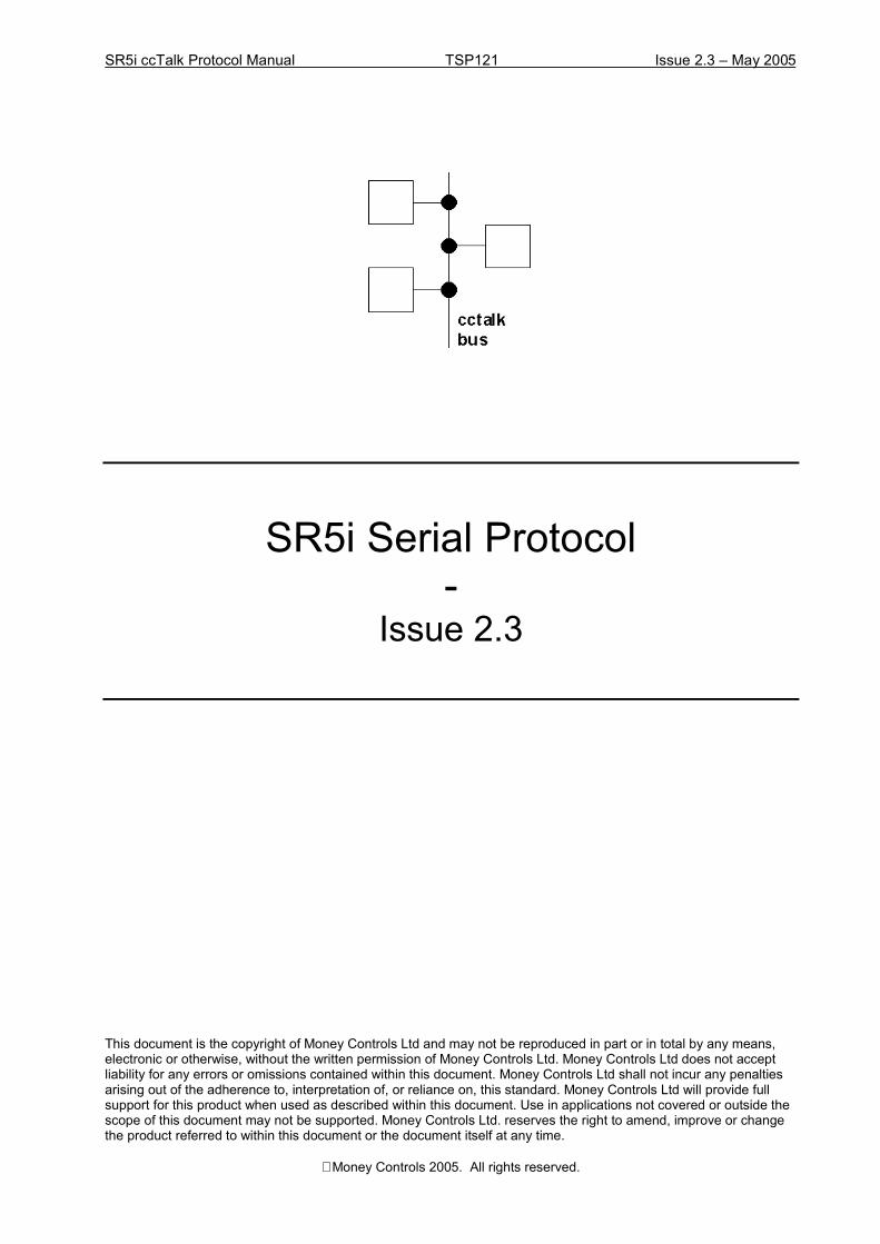
View of PCB pin header from front
Only 3 wires are required for the interface between a SR5i and the host machine.
(1) /DATA(7) +12V(8) 0V
(9) /SERIAL MODE
Pin 9 should be tied to 0V on the connector ( pins 2 or 4 can be used rather than pin 8 ) tooperate the SR5i in serial mode.
The data pin on SR5i is pulled up to +5V via a 10K resistor and should be driven with an open-collector transistor.
Pin 5 is a hardware /RESET line but no connection needs to be made. A software reset commandis provided for this purpose.
8. Quick Start
If you have just received a SR5i then you are probably keen to see if you can get it to work. Thefirst step is sending and receiving cctalk messages and the second step is accepting coins.
First of all is the electrical interface. If you are using a PC-based system with a RS232 port thenyou will need to construct a �RS232 to cctalk� converter which basically level-shifts the ±12V ofRS232 into the +5V/0V voltages of cctalk as well as combine separate TX and RX lines into asingle bi-directional data line. The circuit needed is listed as �Circuit 4� in the generic cctalkspecification. Alternatively a suitable interface box can be ordered from Money Controls - P/NAPC INT XX 00001
The coin acceptor needs to be supplied on the cctalk connector with a regulated +12V DCsupply.
Connect the PC to the coin acceptor on the 10-way cctalk connector. Make sure that pin 9 is tiedto 0V to put SR5i in serial mode.
Using your chosen programming language, try sending a simple poll command to the UART portat 9600 baud with no parity and 8 data bits.
TX = 002 000 001 254 255
9 7
10 8
5 3 1
6 4 2

SR5i ccTalk Protocol Manual TSP121 Issue 2.3 � May 2005
Money Controls 2005. All rights reserved.Page 8 of 50
Note these are the actual byte values sent in decimal. Each value is in the range 0 to 255. Theyshould be sent out in quick succession - no more than 50ms between bytes.
There should be a reply from the SR5i. If not, something is seriously wrong with the hardware.This can be best looked at by connecting an oscilloscope to the cctalk data line and actuallyobserving the data sent back and to.
As cctalk connects the TX line to the RX line, an identical copy of the TX message should beseen first. If not, the �local loop-back� is not working.
RX = 002 000 001 254 255 001 000 002 000 253
The reply from the coin acceptor should be seen in the receive buffer after the transmit message.
RX = 002 000 001 254 255 001 000 002 000 253
If the reply part is missing then the coin acceptor is not working or configured incorrectly. Makesure you wait long enough for the reply to come back - in this case at least 10ms.
How do you find out where the receive message is in the receive buffer ? Easy :-Receive message index = 5 + 2nd byte value, assuming index starts at zero.The data length of any cctalk message is contained in the 2nd byte and the total length is thisvalue + 5.If the coin acceptor returns data rather than an ACK, this can be found as well.Receive data index = 9 + 2nd byte valueReceive data length = contents[ 6 + 2nd byte value ]
Assuming the simple poll works, you can enable all the coins next.
( from this point on we do not show the local loop-back )
TX = 002 002 001 231 255 255 022RX = 001 000 002 000 253
Then a software loop is required to poll the coin acceptor every 200ms for credits.
Do { TX = 002 000 001 229 024 RX = 001 011 002 000 000 000 000 000 000 000 000 000 000 000 000 242 wait 200ms }While True
With this software running, the coin acceptor should now accept coins from the currency it wasprogrammed for.
Each event, whether it be a credit, reject coin, fraud attempt, coin jam or other error, will cause achange in the return data. The next section explains the format of this data.
SR5i ccTalk Protocol Manual TSP121 Issue 2.3 � May 2005
Money Controls 2005. All rights reserved.Page 9 of 50
9. Credit Polling
Coin credits are obtained by polling the coin acceptor at regular intervals using the �Readbuffered credit or error codes� command. Up to 5 credits ( or events ) are stacked in the returnbuffer.
The return data is 11 bytes in length.
[ event counter ][ result 1A ] [ result 1B ][ result 2A ] [ result 2B ][ result 3A ] [ result 3B ][ result 4A ] [ result 4B ][ result 5A ] [ result 5B ]
Note that as per the generic specification, the event counter wraps from 255 to 1 duringnormal operation. A value of zero indicates a power-down or reset has occurred with thepossible loss of some credits.
9.1 Credit Poll Timeout
SR5i has a safety mechanism such that if the unit is not polled with cctalk header 229 for aspecified time then it inhibits itself and cannot take any more coins. This prevents coinswallowing if a fault develops with the host machine.
See Key Timing Parameters.
10. Coin Inhibits
10.1 Individual Coin Inhibits
Each of the 16 coin positions is controlled by a bit flag in a 16-bit register. If the bit is set thenthe coin is enabled for acceptance but if the bit is clear it will always reject. The cctalk header231, Modify inhibit status, sends the 16-bit inhibit register to the coin acceptor. The LSB is sentfirst, controlling coins 1 to 8, followed by the MSB controlling coins 9 to 16.
In serial mode, when SR5i is powered-up or reset, all coins are disabled.
SR5i ccTalk Protocol Manual TSP121 Issue 2.3 � May 2005
Money Controls 2005. All rights reserved.Page 10 of 50
As an example, this is how to enable coins 2, 7 and 13.
Modify inhibit statusTX = 002 002 001 231 066 016 194RX = 001 000 002 000 253
Coin position 87654321LSB = 066 decimal = 01000010 binaryCoin position 87654321 + 8MSB = 016 decimal = 00010000 binary
Coins 2, 7 and 13 are enabled. All other coins are disabled.
10.2 Master Inhibit
There is a �Modify master inhibit status� command, header 228. This command is the equivalentof disabling all coins with the �Modify inhibit status� command described above but theoperating state is stored in EEPROM. So if a master inhibit is applied to SR5i and powerremoved, at the next power-up all coins will be inhibited until the master inhibit condition islifted.
The master inhibit command is slow to execute compared to the individual coin inhibits. If anapplication requires on-the-fly coin inhibiting then header 231 should be used but remember thatthere is some latency associated with serial operation. Sending header 231 will take at least 7msand once the coin has reached the end of the validation sensor area and the accept gate hasopened, it is too late to inhibit it. For precise control of coin acceptance consider using header162, �Modify inhibit and override registers� which allows a current coin and next coin inhibitcondition to be set. Most applications however only configure inhibits during the initialisationroutine and timing is not an issue.
Examples of master inhibit use.
Disable coin acceptor�Modify master inhibit statusTX = 002 001 001 228 000 024RX = 001 000 002 000 253
Enable coin acceptor�Modify master inhibit statusTX = 002 001 001 228 001 023RX = 001 000 002 000 253

SR5i ccTalk Protocol Manual TSP121 Issue 2.3 � May 2005
Money Controls 2005. All rights reserved.Page 11 of 50
10.3 Inhibits versus Serial Credit Code versus Coin Position
On SR5i there is a one-to-one correspondence between inhibit position, serial credit code andcoin position for changing sorter paths, remote programming and reading coin identifiers. Thiskeeps host software simple, logical and consistent.
Inhibit Position Serial Credit Code Coin Position1 1 12 2 23 3 34 4 45 5 56 6 67 7 78 8 89 9 910 10 1011 11 1112 12 1213 13 1314 14 1415 15 1516 16 16
11. Sorter Operation
When operating serially, SR5i automatically selects EEPROM routing mode. In parallel modethere is a choice between the routing plug ( an externally wired connector ) and EEPROM.
SR5i supports an active 4-way sorter as well as an additional 2-way diverter ( the �activemanifold� ) to give a maximum 8-way coin sort. The reject coin channel is separate to this.
Each of the 8-way sorter routes is specified in cctalk by a number 1 to 8. When using a 4-waysorter module only numbers 1 to 4 are needed but numbers 5 to 8 have an equivalent mapping inthe 4-way system and can still be used. 4-way routes are traditionally specified with the letters A,B, C and D and this is shown in the table below.
cctalkRouteCode
cctalkOverride
Bit Position
8-wayRoute
Number
4-wayRouteLetter
RoutingPlug Pin
ParallelOverride
Pin
8-wayManifoldActive ?
1 0 1 D 7 9 Yes2 1 2 C 13 8 Yes3 2 3 B 15 7 Yes4 3 4 A - 6 Yes5 4 5 a - 5 No6 5 6 b - 4 No7 6 7 c - 3 No8 - 8 d - - No

SR5i ccTalk Protocol Manual TSP121 Issue 2.3 � May 2005
Money Controls 2005. All rights reserved.Page 12 of 50
The route numbers and letters refer to physical exit positions. Looking down from the front ofthe coin acceptor ( coin accept gate side ), the sorter exits appear as�
C BD A’(4-way )
or
8 7 6 5’1 2 3 4(8-way)
’ = Zero Power Path, the path taken by the coin if the solenoids do not activate for some reason.
The default sorter route or cashbox path for a 4-way sorter is usually A ( programmed as 5 ) andfor a 8-way sorter is 8.
On SR5i, each coin is programmed with 4 sorter routes. The first route specified is always usedunless there is a �sorter override� on that route. The host machine usually supplies an overridewhen coins can no longer exit on that route - for instance if the payout tube or hopper is full.When this occurs, the next �free� route is selected. If all 4 routes have overrides applied then thecoin is diverted down the default sorter route - even if there is an override on this route. Thecctalk command headers 188 & 189 can be used to change the default sorter route if the factoryconfiguration setting is not suitable for your application.
Overrides cannot be applied to route 8.
When SR5i is operating in serial mode, sorter routes are obtained from EEPROM and not the�routing plug� connector.
Remember�
Sorter routes are applied to coins-
Sorter overrides are applied to routes
11.1 Sorter : Worked Example
Suppose the host machine sends these 2 commands to SR5i�
Modify sorter pathsTX = 002 005 001 210 001 004 007 005 006 015RX = 001 000 002 000 253

SR5i ccTalk Protocol Manual TSP121 Issue 2.3 � May 2005
Money Controls 2005. All rights reserved.Page 13 of 50
Modify sorter override statusTX = 002 001 001 222 055 231RX = 001 000 002 000 253
The first command assigns sorter routes 4, 7, 5, 6 to coin 1.
The second command assigns sorter override 55.
55 decimal = 37 hex = 0011 0111 binary.
0 = override, 1 = normal.
Route x765 4321Status 0011 0111
So overrides are applied to routes 4 & 7.
Therefore coin 1 will try to go to route 4 but this has an override applied. It will then try to go toroute 7 but this has an override applied as well. So coin 1 will actually go to route 5.
If routes 5 & 6 had overrides applied then coin 1 would go to the default path - whatever that is.
If sorter overrides are not used then it is best to set all sorter routes to the same value.
Modify sorter pathsTX = 002 005 001 210 001 005 005 005 005 017RX = 001 000 002 000 253
Coin 1 will be routed to path 5.
11.2 �On the Fly� Routing
The Modify sorter paths command writes to EEPROM and while this is done no coins can beaccepted as the acceptor switches into a �program� mode for a few hundred milliseconds. It istherefore recommended that sorter paths for each coin are configured at power-up or after areset, and any subsequent changes are done with the Modify sorter override status command.Overrides are written to RAM - the command is executed quickly and it does not interfere withnormal coin acceptance.
12. DCE Rundown & Tokens
DCE = Dual Coin Entry for tokens.
As well as 16 coins, SR5i has memory for an additional 6 tokens. Token position 6 is normallyreserved for a �teach and run� token with the other 5 token positions factory programmed.

SR5i ccTalk Protocol Manual TSP121 Issue 2.3 � May 2005
Money Controls 2005. All rights reserved.Page 14 of 50
The operation of SR5i is such that only 1 of the tokens can be enabled at a time and this tokenwill replace 1 or 2 of the coin positions. A typical configuration is shown below.
Coin Position No Tokens With Tokens1 Coin 1 Coin 12 Coin 2 Coin 23 Coin 3 Coin 34 Coin 4 Coin 45 Coin 5 Token6 Coin 6 Coin 57 Coin 7 Coin 68 Coin 8 Coin 79 Coin 9 Coin 810 Coin 10 Coin 911 Coin 11 Coin 1012 Coin 12 Coin 1113 Coin 13 Token14 Coin 14 Coin 1215 Coin 15 Coin 1316 Coin 16 Coin 14
In this case, the selected token is used instead of the coins programmed at positions 5 and 13.
In parallel mode the token is selected on the rotary switch at power-up but in serial mode thetoken can be selected with cctalk header 177, �Handheld function�.
For example�
Handheld function : Select tokenTX = 002 002 001 177 001 001 072RX = 001 000 002 000 253 - ACK
This selects token 1. Use 6 or 12 for the �teach and run� token, or 0 for no tokens.
At power-up, the default token is always 6 ( = �teach and run� ).
When reading the coin identifiers with cctalk header 184, requesting a token position will return�Token � rather than the usual format.
The credit code and sorter paths for the token are provided at the equivalent coin position. So toset a sorter route for the token change the sorter route for coin 5.

SR5i ccTalk Protocol Manual TSP121 Issue 2.3 � May 2005
Money Controls 2005. All rights reserved.Page 15 of 50
12.1 Token mode selection
SR5i can operate in 3 states�
The switch between industry-standard mode and DCE mode is made via a configuration flag inEEPROM.
12.1.1. Industry-standard mode
15 coins + 1 token from 6
or 14 coins + 1 token from 6 if a token is available in the upper and lower bank of coins
Coins and tokens are enabled concurrently and any enabling / disabling of tokens must be donethrough inhibits.
12.1.2. DCE mode with DCE rundown plugged in
15 coins + 1 token from 6
or 14 coins + 1 token from 6 if a token is available in the upper and lower bank of coins
Coins and tokens are mutually exclusive. Coins are enabled if a coin is put down the coin side ofthe DCE and tokens are enabled if a token is put down the token side of the DCE.
12.1.3. DCE mode without using DCE rundown
16 coins only.
In this mode the full 16 coin positions are available without any token substitution. The tokenbank is not used.
13. Teaching Coins and Tokens
It is possible for SR5i to learn a new coin or token by repeated insertion. This �teach and run�mode can be entered and controlled using cctalk serial commands.
Header202, �Teach mode control�Header 201, �Request teach status�
To enter teach mode, send�
Teach mode controlTX = 002 001 001 202 004 046RX = 001 000 002 000 253Coin position 4 is specified for teaching.
Then poll until teach complete. The coin acceptor decides when you have put enough coins ortokens in to successfully complete the task. This will be 8 or more. If the coins or tokens you putin are very different to each other then many more insertions will be required or it may not bepossible at all.

SR5i ccTalk Protocol Manual TSP121 Issue 2.3 � May 2005
Money Controls 2005. All rights reserved.Page 16 of 50
Request teach statusTX = 002 001 001 201 000 051RX = 001 002 002 000 000 254 253
[ status code ] = 254 = Teaching in progress
Insert a coin�Request teach statusTX = 002 001 001 201 000 051RX = 001 002 002 000 001 254 252
Insert a coin�Request teach statusTX = 002 001 001 201 000 051RX = 001 002 002 000 002 254 251
Insert last coin ( at least 8, in this case 10 )�
Request teach statusTX = 002 001 001 201 000 051RX = 001 002 002 000 010 255 242
[ status code ] = 255 = Teach completed
Note that teach must be enabled through a factory configuration option before it can be used.
When a coin is taught, the coin identifier is automatically set to �TEACH �.
Coins 1 to 16 can be taught as well as a single token position - the �teach and run� token. Toteach the token, specify coin position 17.
To accept the teach token in parallel mode the rotary switch must be set to �C�, but for serialoperation select token position 6 or 12 with cctalk header 177. Token 6 is selected by default atpower-up. The value of 12 is compatible with older products such as SR5 and SR5R.

SR5i ccTalk Protocol Manual TSP121 Issue 2.3 � May 2005
Money Controls 2005. All rights reserved.Page 17 of 50
14. MechTool
MechTool is a way of changing configuration data without external programming equipment. Ituses the SR5i rotary switch and push button.
For security MechTool only works in parallel mode. If you are using a serial connector,remove it and apply power through the parallel connector. Alternatively, break the pin 9link to 0V.
Each MechTool mode is engaged by turning the rotary switch to the desired position, setting thebank select DIP switches to the required state, and pressing the push button for at least 1s. TheLED should change colour to indicate the change to the operating state has been completedsuccessfully.
The entries in YELLOW below indicate changes to the serial configuration.
Rotary Switch Function Bank Select 1 Bank Select 20 Special Flash Programming Mode0 Token disabled BS1 BS21 Select token 1 BS1 BS22 Select token 2 BS1 BS23 Select token 3 BS1 BS24 Select token 4 BS1 BS25 Select token 5 BS1 BS26 Routing Replication - -
7 Power-up diagnostics Up = Enable diagnosticsDn = Disable diagnostics
-
8 Debugging Up = Pulse solenoidsDn = No action
-
9 EEPROM routeprogramming
Up = Reset to defaultDn = No action
Up = Swallow plugDn = No action
A Modify cctalk addressChoose 2, 11, 12, 13
Up = 1Dn = 0
Up = 1Dn = 0
B Encryption key Up = Reset to factoryDn = No action
Up = Clear maintenance LEDDn = No action
C Select teach token BS1 BS2
D Operating mode Up = DCE rundownDn = Industry standard
Up = Alarms offDn = Alarms on
E Routing control Up = Routing PlugDn = EEPROM
-
F Teach new token - -

SR5i ccTalk Protocol Manual TSP121 Issue 2.3 � May 2005
Money Controls 2005. All rights reserved.Page 18 of 50
14.1 Operating Notes
14.1.1. Token Selection
Rotary switch positions 1 to 5 and C select the token to accept. The switch position is read atpower-up or reset, but may be changed at any time by pressing the push button for at least 1s.
14.1.2. Token Teach
To teach a token in parallel mode, select position F and press the push button for at least 1s.When the LED turns red, enter at least 8 coins or tokens until the LED turns green. The tokenshould now accept. Remember to change the switch position to C so that the teach token will beaccepted at the next power-up.
14.1.3. Address Selection
The cctalk address may be changed for applications which require more than one coin acceptoron the same bus.
BS1 BS2 AddressDown Down 2
Up Down 11Down Up 12
Up Up 13
Addresses 3 to 10 are reserved for serial hoppers.
It is strongly recommended that all single coin acceptor applications use cctalk address 2 whichis the factory default.
14.1.4. EEPROM route programming
The first switch enables all the sorter routes in EEPROM to be changed to the default sorter route( usually 5 ).
The second switch allows a routing plug to be copied or �swallowed� to EEPROM. Once this isdone, the routing plug can be removed and the coins will be routed in an identical manner. Thelegacy routing plug allows any of 7 coins to be routed to 3 paths ( in the order D then C then B ).This function also programs the default sorter path for coin 8 and copies the paths from the lowerbank to the upper bank ( coins 1..8 to 9..16 ).
If both switches are up then the plug swallowing has priority.
The sorter must be enabled ( factory option ) for these functions to work.

SR5i ccTalk Protocol Manual TSP121 Issue 2.3 � May 2005
Money Controls 2005. All rights reserved.Page 19 of 50
14.1.5. Routing Replication
With a cctalk 1:1 ribbon cable, it is possible to connect a SR5i to another 5inch cctalk validatorand copy the EEPROM sorter path configuration. Power should be applied through the parallelconnector on SR5i and then only the cctalk cable used to connect the two products. All 4 routesfor all 16 coins are replicated.
14.1.6. Power-up Diagnostics
This flag setting controls whether SR5i checks the sensor and thermistor readings at power-upfor an out-of-range error. If a fault condition is detected then no coins can be accepted.
14.1.7. Solenoid Pulsing
The solenoid duty cycle is 500ms on, 500ms off.
If the sorter is enabled on the SR5i then the software cycles through a solenoid test sequence�
[ Accept Gate ] ! [ Lower Sorter Flap ] ! [ Upper Sorter Flap ] ! [ Manifold Flap ] !
If the sorter is disabled the only the accept gate solenoid is pulsed.
[ Accept Gate ] ! [ Accept Gate ] ! [ Accept Gate ] ! [ Accept Gate ] !
14.1.8. Encryption Key Recovery
The encryption key can be changed back to the factory value ( as shown on the product label ) ifit has been changed / stored with cctalk headers 137 / 136 and then �lost�. This function is onlyof interest if the SR5i has been ordered with encryption enabled.
15. Key Timing Parameters
Description TimePower-up : Initialisation time < 200msSoftware reset : Initialisation time < 200msCredit poll timeout 1s
Host machine software should wait for the initialisation time in the table above beforecommunicating with the SR5i after a power-up or reset. An attempt before then will mostlylikely not receive any reply, or if a �Perform self-check� is done then an incorrect fault codecould be reported.
The credit poll timeout requires SR5i to be polled at this time interval or less to prevent the coinacceptor inhibiting itself.

SR5i ccTalk Protocol Manual TSP121 Issue 2.3 � May 2005
Money Controls 2005. All rights reserved.Page 20 of 50
16. Typical Command Response Times
Examples of cctalk response times are shown in the table below. They are meant to be indicativeonly.
Header Description Total TX + RXPacket Length
TypicalResponseTime α
TypicalResponseTime β
96:247 Calculate ROM secure signature 19 2.68s 2.68s197 Calculate ROM checksum 14 996 ms 1000 ms232 Perform self-check 11 40 ms 43 ms228 Modify master inhibit status 11 15 ms 18 ms246 Request manufacturer id 24 3 ms 9 ms229 Read buffered credit or error codes 21 3 ms 8 ms242 Request serial number 13 3 ms 5 ms226 Request insertion counter 13 3 ms 5 ms231 Modify inhibit status 12 3 ms 5 ms254 Simple poll 10 3 ms 5 ms001 Reset device 10 3 ms 5 ms
α : No encryptionβ : With encryption
The typical response time is most easily measured from the start of the final stop bit of thetransmitted message to the start bit of the reply.
17. Debugging : No reply to any command ?
There are various reasons why there may be no reply to a cctalk serial command. Try checkingthe following items.
17.1 Power
Is there sufficient power applied to SR5i ? There is an on-board voltage regulator which requiresa regulated DC supply voltage in the range 10 to 26V. A current source of 2A will be required tooperate the coin acceptor and sorter module. If there is insufficient current during coinacceptance the processor can �reset� and you may find trapped or mis-sorted coins. Alsocommunication errors will increase.
17.2 Comms Data Format
When data to be transmitted is shown in this document as�TX = 002 000 001 254 255this means send 5 bytes of data with the DECIMAL VALUES shown, not in ASCII !

SR5i ccTalk Protocol Manual TSP121 Issue 2.3 � May 2005
Money Controls 2005. All rights reserved.Page 21 of 50
So the data loaded into the transmit buffer is�
txBuffer[0]=2txBuffer[1]=0txBuffer[2]=1txBuffer[3]=254txBuffer[4]=255
In Visual Basic the message can be converted to a string and sent as�txString = Chr(2) + Chr(0) + Chr(1) + Chr(254) + Chr(255)though it is more efficient to work with binary data as cctalk packets mostly comprise non-displayable characters.
17.3 Address
The default SR5i address is 2 but this can be changed by writing to the configuration memory.Try using the broadcast address ( = 0 ) with no other devices connected to the bus. Is there areply ? If so, try using header 253, �Address poll� to find out the address.
17.4 Data Voltages & Timing
If you have access to an oscilloscope then attach a probe to the data line and check the signalvoltages when a message packet is sent. The quiescent state of the cctalk data line is high (between 4V and 5V ) and the active state is low ( less than 0.5V ). Each message byte at 9600baud should take 1.04ms for a start bit, 8 data bits and a stop bit. It will only be possible tomeasure from the beginning of the start bit to the beginning of the stop bit ( 9 bits total = 938us )when bit 7 of the data byte is 0. The baud rate should be within 2% of nominal. The rise / falltime should be less than 10us. The waveform should look �clean� with no visible noise.
For each complete cctalk packet the timing between bytes should be less than 50ms. If this timeis exceeded anywhere in the packet then SR5i will timeout and reset the receive pointer. Therewill be no reply as the packets received will be incomplete.
The timing between a command or request for data and the response from SR5i varies with eachcommand. Most commands are replied to within a few ms but some programming commandstake over one second.
17.5 Command Header
Is the command header supported by SR5i ? Although it is listed in the generic specification itmay not be supported on SR5i. Check the command list in this document.
If a command header is not support there is no reply from SR5i.

SR5i ccTalk Protocol Manual TSP121 Issue 2.3 � May 2005
Money Controls 2005. All rights reserved.Page 22 of 50
17.6 Checksum
If the message checksum is not calculated correctly then there is no reply from SR5i.
Here is an example of a checksum calculation for the modify inhibit status command.TX = 002 002 001 231 255 255 022
022 = 256 - (002 + 002 + 001 + 231 + 255 + 255) mod 256 = 256 - 234 = 22
17.7 TX Loop-back
The cctalk protocol uses a single bi-directional data line which means that any TX message bytesappear immediately on the RX pin. Even if SR5i does not reply, the TX message should bereceived in full. If it does not then there is a definitely a hardware fault.
17.8 Encryption
It is possible that SR5i was ordered with encryption enabled in which case no reply will be madeto any cctalk command unless the 6-digit security key is known in advance.

SR5i ccTalk Protocol Manual TSP121 Issue 2.3 � May 2005
Money Controls 2005. All rights reserved.Page 23 of 50
18. Command List
The following table shows all the cctalk commands currently available for customer use on SR5i.More details can be found in the generic specification.
Any [ data bytes ] are shown in decimal.
MDCES = Multi-Drop Command Extension Set. These commands are only used whenperipheral addresses are unknown.
Header numbers are shown in descending order by convention.
Header Function Returned Data / Comments254 Simple poll ACK returned.253 Address poll MDCES support252 Address clash MDCES support251 Address change MDCES support250 Address random MDCES support249 Request polling priority [ 1 ] [ 200 ] = 200 ms248 Request status [ 0 ] = �OK�
[ 1 ] = �Flight deck open�247 Request variable set 9 bytes of Money Controls internal data246 Request manufacturer id �Money Controls�245 Request equipment category id �Coin Acceptor�244 Request product code �SR5i�243 Request database version [ 0 ] if no calibration support, otherwise new
coin sets can be remotely programmed.242 Request serial number Range 0 to 16,777,215241 Request software revision e.g. �CRS-F1-V1.08�240 Test solenoids Bit 0 = Accept gate
Bit 1 = Lower sorter flapBit 2 = Upper sorter flapBit 3 = 8-way Manifold flap ( if used )Pulsed for 500ms. The ACK is returned afterthe output pulse has finished.
238 Test output lines Bit 0 = A1 parallel outputBit 1 = A2Bit 2 = A3Bit 3 = A4 ( STROBE pin )Bit 4 = A5Bit 5 = A6 ( IDENT pin )Bit 6 = Tri-colour LED to GreenBit 7 = Tri-colour LED to RedPulsed for 500ms. The ACK is returned afterthe output pulse has finished.

SR5i ccTalk Protocol Manual TSP121 Issue 2.3 � May 2005
Money Controls 2005. All rights reserved.Page 24 of 50
237 Read input lines For low level diagnostics only.12 bytes returned�[ Byte 1 ]
Bits 3:0 = rotary switchBit 4 = push button ( 0 = pressed )Bits 7:5 = zero
[ Byte 2 ]Bit 0 = bank select 1 ( 0 = ON )Bit 1 = bank select 2Bits 7:2 = zero
[ Byte 3 ]Bit 0 = credit select line ( 0 = binary /BACTA mode )Bit 1 = override 1 ( 0 = override active )Bit 2 = override 2Bit 3 = override 3Bit 4 = override 4Bit 5 = override 5Bit 6 = override 6Bit 7 = override 7
[ Byte 4 ]Bits 7:0 = parallel inhibits ( 0 = enablecoin )
[ Byte 5 ]Bits 6:0 = routing plug value withno drive signal ( = F8 hex )Bit 7 = one
[ Byte 6 ]Bits 6:0 = routing plug value for coin 1Bit 7 = zero( bit 0 = route 1 � bit 6 = route 7 )
[ Byte 7 ]Bits 6:0 = routing plug value for coin 2Bit 7 = zero
[ Byte 8 ]Bits 6:0 = routing plug value for coin 3Bit 7 = zero
[ Byte 9 ]Bits 6:0 = routing plug value for coin 4Bit 7 = zero
[ Byte 10 ]Bits 6:0 = routing plug value for coin 5Bit 7 = zero
[ Byte 11 ]Bits 6:0 = routing plug value for coin 6Bit 7 = zero
[ Byte 12 ]Bits 6:0 = routing plug value for coin 7
Bit 7 = zero236 Read opto states Bit 0 = DCE Coin opto ( 1 = blocked / not
fitted )Bit 1 = DCE Token optoBit 2 = Sorter optosSorter optos cannot be tested individually -they are combined in series.
SR5i ccTalk Protocol Manual TSP121 Issue 2.3 � May 2005
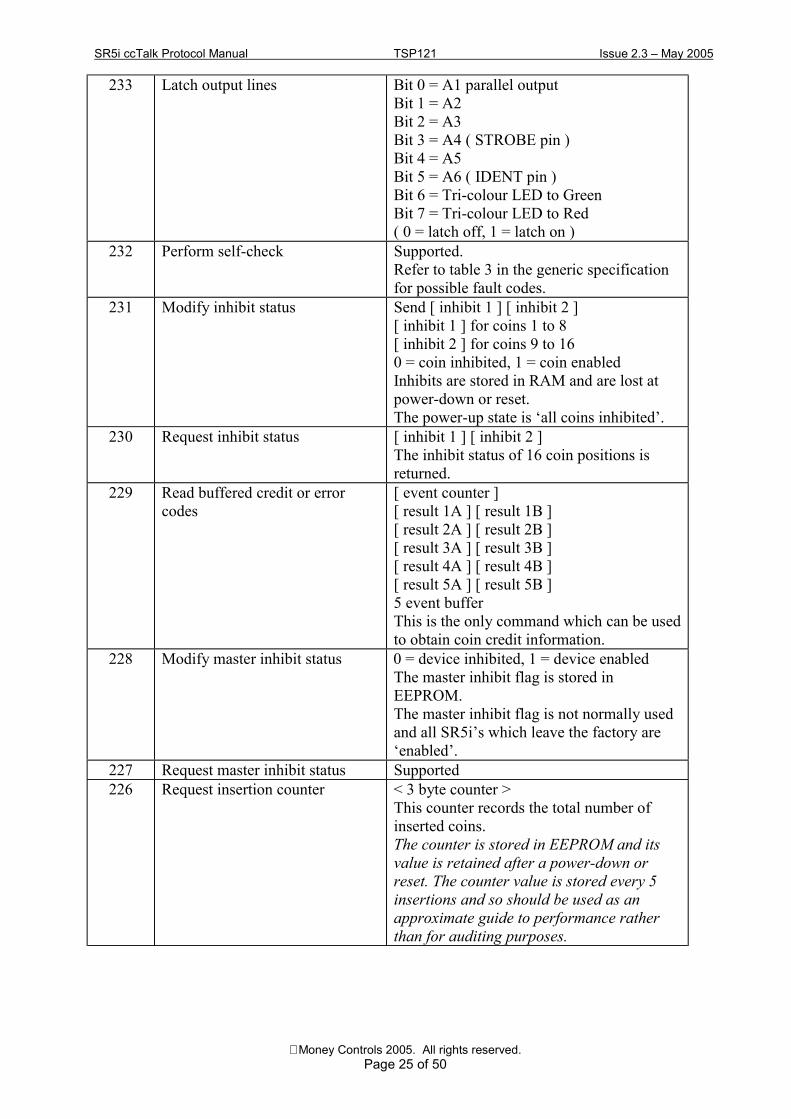
Money Controls 2005. All rights reserved.Page 25 of 50
233 Latch output lines Bit 0 = A1 parallel outputBit 1 = A2Bit 2 = A3Bit 3 = A4 ( STROBE pin )Bit 4 = A5Bit 5 = A6 ( IDENT pin )Bit 6 = Tri-colour LED to GreenBit 7 = Tri-colour LED to Red( 0 = latch off, 1 = latch on )
232 Perform self-check Supported.Refer to table 3 in the generic specificationfor possible fault codes.
231 Modify inhibit status Send [ inhibit 1 ] [ inhibit 2 ][ inhibit 1 ] for coins 1 to 8[ inhibit 2 ] for coins 9 to 160 = coin inhibited, 1 = coin enabledInhibits are stored in RAM and are lost atpower-down or reset.The power-up state is �all coins inhibited�.
230 Request inhibit status [ inhibit 1 ] [ inhibit 2 ]The inhibit status of 16 coin positions isreturned.
229 Read buffered credit or errorcodes
[ event counter ][ result 1A ] [ result 1B ][ result 2A ] [ result 2B ][ result 3A ] [ result 3B ][ result 4A ] [ result 4B ][ result 5A ] [ result 5B ]5 event bufferThis is the only command which can be usedto obtain coin credit information.
228 Modify master inhibit status 0 = device inhibited, 1 = device enabledThe master inhibit flag is stored inEEPROM.The master inhibit flag is not normally usedand all SR5i�s which leave the factory are�enabled�.
227 Request master inhibit status Supported226 Request insertion counter < 3 byte counter >
This counter records the total number ofinserted coins.The counter is stored in EEPROM and itsvalue is retained after a power-down orreset. The counter value is stored every 5insertions and so should be used as anapproximate guide to performance ratherthan for auditing purposes.

SR5i ccTalk Protocol Manual TSP121 Issue 2.3 � May 2005
Money Controls 2005. All rights reserved.Page 26 of 50
225 Request accept counter < 3 byte counter >This counter records the total number ofaccepted coins.The counter is stored in EEPROM and itsvalue is retained after a power-down orreset. The counter value is stored every 5insertions and so should be used as anapproximate guide to performance ratherthan for auditing purposes.
222 Modify sorter override status Bit 0 = override route 1 ( 0 = override )Bit 1 = override route 2Bit 2 = override route 3Bit 3 = override route 4Bit 4 = override route 5Bit 5 = override route 6Bit 6 = override route 7Bit 7 = 0 { not used )Overrides are stored in RAM and are lost atpower-down or reset.The power-up state is �no overrides�.
221 Request sorter override status Supported219 Enter NEW PIN number ACK returned for compatibility with older
products but the PIN number mechanism isnot used to protect any commands.
218 Enter PIN number ACK returned for compatibility with olderproducts but the PIN number mechanism isnot used to protect any commands.
216 Request data storage availability [ 2 ] [ 2 ] [ 8 ] [ 2 ] [ 8 ]This indicates a small amount of EEPROMstorage is available for customer use�2 blocks of 8 bytes for reading2 blocks of 8 bytes for writing
215 Read data block Block number = 0 or 1214 Write data block Block number = 0 or 1213 Request option flags Bit 0 = credit code format
[ 0 ] = coin position, default[ 1 ] = CVF, not supported
212 Request coin position SupportedReturns position of coins with specifiedcctalk credit codes.

SR5i ccTalk Protocol Manual TSP121 Issue 2.3 � May 2005
Money Controls 2005. All rights reserved.Page 27 of 50
210 Modify sorter paths [ coin position ][ path 1 ] [ path 2 ] [ path 3 ] [ path 4 ]coin position : coin 1 to 16path : route 1 to 8route 1 " D ( 4-way� )route 2 " Croute 3 " Broute 4 " Aroute 5 " a ( 8-way� )route 6 " broute 7 " croute 8 " dSorter paths are stored in EEPROM.
209 Request sorter paths 4 paths returned for each coin position.202 Teach mode control [ coin position ]
Specify 1 to 16 for a coinor 17 for token 6 ( the only one available )The �virtual� rotary switch must be on 6 or12 for the teach token to be accepted.If the teach mechanism has been disabledfor security reasons then the �teach error�code is returned.
201 Request teach status Supported.199 Configuration to EEPROM Stores the current inhibit & override settings
into EEPROM so that they are then used atthe next power-up. Use with caution as thismodifies the factory default settings !
197 Calculate ROM checksum A 4 byte ROM checksum of the firmware isreturned to the host machine.[ XX ] [ XX ] [ XX ] [ XX ]
196 Request creation date Supported195 Request last modification date Supported194 Request reject counter < 3 byte counter >
This counter records the total number ofrejected coins.The counter is stored in EEPROM and itsvalue is retained after a power-down orreset. The counter value is stored every 5insertions and so should be used as anapproximate guide to performance ratherthan for auditing purposes.
193 Request fraud counter SupportedThe counter is stored in RAM and is clearedat power-down or reset.Note : Fraud coins can only be counted ifthey are factory pre-programmed into thecoin acceptor and marked as �bad�
192 Request build code Fixed width 8 character ASCII stringe.g. �STD01 �

SR5i ccTalk Protocol Manual TSP121 Issue 2.3 � May 2005
Money Controls 2005. All rights reserved.Page 28 of 50
189 Modify default sorter path [ default path ]Specified as 1 to 8. This is the path the coinis routed to after all the override paths havebeen used.The default path is stored in EEPROM andis used at the next power-up.The default path for 4-way routing is A (5).The default path for 8-way routing is 8.
188 Request default sorter path Supported185 Modify coin id Supported
6 x ASCII characters e.g. EU200AIt is not recommended that factory settingsare changed. When remote programmingnew coins, the coin id is automaticallyupdated.
184 Request coin id Supported182 Download calibration info Supported. 101 bytes in length.
Internal use only.181 Modify security setting Security settings are inherent and not
adjustable directly on the �i� series coinacceptors but an ACK is returned forbackwards compatibility.
180 Request security setting Security settings are inherent and notadjustable directly on the �i� series coinacceptors. [ 0 ] is returned for backwardscompatibility.
179 Modify bank select [ bank no. ]0 = default ( both banks enabled )1 = bank 1 only enabled ( coins 1 to 8 )2 = bank 2 only enabled ( coins 9 to 16 )The action of this command is the same asusing the �Modify inhibit status� command.
177 Handheld function Low level engineering functions�mode = 0 : function = 0
read rotary switchmode = 0 : function = 1, [ token ]
select token to be usedmode = 0 : function = 2, [ coin ]
read route value for given coin( routing plug mode )
mode = 0 : function = 5fix EEPROM checksum
176 Request alarm counter [ alarm count ]The alarm counter is stored in RAM and iscleared at power-down or reset.Additionally, it is cleared after eachrequest and so should be used cumulatively.Alarm conditions�a) blocked sorter exit optosb) blocked credit sensorc) coin going backwards detection
173 Request thermistor reading Supported

SR5i ccTalk Protocol Manual TSP121 Issue 2.3 � May 2005
Money Controls 2005. All rights reserved.Page 29 of 50
170 Request base year �2003�169 Request address mode [ 132 ]
Address is stored in EEPROM and may bechanged serially ( non-volatile ).
162 Modify inhibit and overrideregisters
Supported
137 Switch encryption code Supported136 Store encryption code Supported
96:255 Begin packet upload Start remote programming
96:254 Upload packet data Send data packets
96:253 End packet upload & program Finish remote programming
96:252 Modify coin signature Not supported
96:251 Request coin signature Not supported
96:250 Verify coin signature Not supported
96:249 Remove coin signature Delete a coin signature from memory. Thispermanently stops a coin from beingaccepted rather than modifying the inhibits.
96:248 Request extended coin id The extended coin id contains 2 extracharacters at the end which reflect windowsecurity.8 x ASCII characters e.g. EU100A-2
96:247 Calculate ROM secure signature The ROM checksum is calculated with a 32-bit seed and uses a more secure algorithm.
96:246 Upload key file data Internal use onlye.g. SR5i-1-1.binSize = 1 + 7 x 11 x 2 = 155 bytes
96:245 Remove all coin signatures Deletes all coin signatures from memory. Becareful - there is no �undo� command !
96:244 Request currency code Returns 8 x ASCII characters e.g. EU96:243 Request coin issue Returns 5 x ASCII characters e.g. 00001
4 Request comms revision [ 1 ] [ 4 ] [ 2 ]cctalk specification = 4.2minor revision = 1
3 Clear comms status variables Supported2 Request comms status variables Supported1 Reset device Supported
This command performs a �software reset�.

SR5i ccTalk Protocol Manual TSP121 Issue 2.3 � May 2005
Money Controls 2005. All rights reserved.Page 30 of 50
19. Event Code Table
This table is taken from the cctalk generic specification.
Shaded = Implemented on SR5i
Code Error0 Null event ( no error )1 Reject coin2 Inhibited coin3 Multiple window4 Wake-up timeout5 Validation timeout6 Credit sensor timeout7 Sorter opto timeout8 2nd close coin error9 Accept gate not ready10 Credit sensor not ready11 Sorter not ready12 Reject coin not cleared13 Validation sensor not ready14 Credit sensor blocked15 Sorter opto blocked16 Credit sequence error17 Coin going backwards18 Coin too fast ( over credit sensor )19 Coin too slow ( over credit sensor )20 C.O.S. mechanism activated
( coin-on-string )21 DCE opto timeout22 DCE opto not seen23 Credit sensor reached too early24 Reject coin ( repeated sequential trip )25 Reject slug26 Reject sensor blocked27 Games overload28 Max. coin meter pulses exceeded128 Inhibited coin ( Type 1 )� Inhibited coin ( Type n )159 Inhibited coin ( Type 32 )253 Data block request ( note α )254 Coin return mechanism activated
( Flight deck open )255 Unspecified alarm code

SR5i ccTalk Protocol Manual TSP121 Issue 2.3 � May 2005
Money Controls 2005. All rights reserved.Page 31 of 50
19.1 Event Code Notes
The �multiple window error� is based on the parallel credit codes. If a coin is validated as true inmore than one coin position with different credit codes then there is an ambiguous conditionwhich cannot be resolved. The coin is rejected and the �multiple window error� issued. It can betreated by the host machine as a normal reject coin.
Internally SR5i is programmed with 3 banks of credit codes�
Parallel 1 of 6 accept lines activeBinary 4-bit binary code with strobe on A4. A6 is always on.cctalk Serial credit codes 1 to 16
The �Reject coin ( repeated sequential trip )� indicates 5 sequential reject coins which maypossibly be a fault condition.

SR5i ccTalk Protocol Manual TSP121 Issue 2.3 � May 2005
Money Controls 2005. All rights reserved.Page 32 of 50
20. Fault Code Table
This table is taken from the cctalk generic specification.
Shaded = Implemented on SR5i
Code Fault Optional Extra Info1 EEPROM checksum corrupted -2 Fault on inductive coils Coil number3 Fault on credit sensor -4 Fault on piezo sensor -5 Fault on reflective sensor -6 Fault on diameter sensor -7 Fault on wake-up sensor -8 Fault on sorter exit sensors Sensor number9 NVRAM checksum corrupted -10 Coin dispensing error -11 Low level sensor error Hopper or tube number12 High level sensor error Hopper or tube number13 Coin counting error -14 Keypad error Key number15 Button error -16 Display error -17 Coin auditing error -18 Fault on reject sensor -19 Fault on coin return mechanism -20 Fault on C.O.S. mechanism -21 Fault on rim sensor -22 Fault on thermistor -23 Payout motor fault Hopper number24 Payout timeout Hopper or tube number25 Payout jammed Hopper or tube number26 Payout sensor fault Hopper or tube number27 Level sensor error Hopper or tube number28 Personality module not fitted -29 Personality checksum corrupted -30 ROM checksum mismatch -31 Missing slave device Slave address32 Internal comms bad Slave address33 Supply voltage outside
operating limits-
34 Temperature outsideoperating limits
-
35 D.C.E. fault 1 = coin, 2 = token36 Fault on bill validation sensor Sensor number37 Fault on bill transport motor -38 Fault on stacker -39 Bill jammed -40 RAM test fail -

SR5i ccTalk Protocol Manual TSP121 Issue 2.3 � May 2005
Money Controls 2005. All rights reserved.Page 33 of 50
41 Fault on string sensor -255 Unspecified fault code -

SR5i ccTalk Protocol Manual TSP121 Issue 2.3 � May 2005
Money Controls 2005. All rights reserved.Page 34 of 50
21. Remote Coin Programming
21.1 Introduction
It is possible to update or completely replace the programmed coins in SR5i with a differentcurrency remotely. This means through the cctalk serial interface and without the manualinsertion of any coins. So from a central office with a server and TCP/IP connection, it would bepossible to obtain the latest coin specification and distribute it through a series of regional officesand site commanders to each individual machine with a SR5i fitted. The final link would becctalk but any serial protocol prior to that could be used. Local buffering would be required tostore the data for at least one coin before programming via cctalk. The memory required to dothis is not large - less than 4K bytes per coin.
8 cctalk commands are associated with remote coin programming. They are currently in theapplication-specific section of the cctalk header table.
96:255 means cctalk header 96 with a sub-header of 255. The sub-header is defined as the firstcctalk data byte. Other data can follow the sub-header where necessary.
• Header 96:255, Begin packet upload• Header 96:254, Upload packet data• Header 96:253, End packet upload & program• Header 96:249, Remove coin signature• Header 96:248, Request extended coin id• Header 96:245, Remove all coin signatures• Header 96:244, Request currency code• Header 96:243, Request coin issue
Central Office
Regional Office
Site Commander
AWP Machine
SR5i SR5i
AWP Machine
Regional Office
Site Commander

SR5i ccTalk Protocol Manual TSP121 Issue 2.3 � May 2005
Money Controls 2005. All rights reserved.Page 35 of 50
21.2 Data Format
Only data fields are shown here for clarity. The rest of the packet is formatted as a normal cctalkmessage. The cctalk header is 96 with a sub-header as shown ( the sub-header is the first cctalkdata byte ).
21.2.1. Sub-Header 255 - Begin packet upload
Transmitted data : <none>Received data : ACK
21.2.2. Sub-Header 254 - Upload packet data
Transmitted data : <variable>Received data : ACK
21.2.3. Sub-Header 253 - End packet upload & program
Transmitted data : [ coin position ]Received data : ACK or [ error code ]
[ coin position ] = 1 to 16
21.2.4. Sub-Header 249 - Remove coin signature
Transmitted data : [ coin position ]Received data : ACK or [ error code ]
[ coin position ] = 1 to 16
21.2.5. Sub-Header 248 - Request extended coin id
Transmitted data : [ coin position ]Received data : [ char 1 ] [ char 2 ] [ char 3 ]� [ char 8 ]
[ coin position ] = 1 to 16
21.2.6. Sub-Header 247 - Calculate ROM secure signature
Transmitted data : [ seed 1 ] [ seed 2 ] [ seed 3 ] [ seed 4 ]Received data : [ signature 1 ] [ signature 2 ] [ signature 3 ] [ signature 4 ]
21.2.7. Sub-Header 245 - Remove all coin signatures
Transmitted data : <none>Received data : ACK or [ error code ]
21.2.8. Sub-Header 244 - Request currency code
Transmitted data : <none>Received data : [ char 1 ] [ char 2 ] [ char 3 ]� [ char 8 ]

SR5i ccTalk Protocol Manual TSP121 Issue 2.3 � May 2005
Money Controls 2005. All rights reserved.Page 36 of 50
21.2.9. Sub-Header 243 - Request coin issue
Transmitted data : [ coin position ]Received data : [ char 1 ] [ char 2 ] [ char 3 ] [ char 4 ] [ char 5 ]
[ coin position ] = 1 to 16
21.3 Programming Procedure
21.3.1. The �.bin� file
Each coin to be programmed has its data in a file with a �.bin� extension. A typical filename for acoin is EU200A-0.bin. The size of each coin file varies in length but will typically be between1.5K and 4K bytes.
The data inside each file is in binary format. The entire file must transferred to SR5i. Nomodifications to the data must be made.
Step 1. Send cctalk command �Begin packet upload�TX data : < none >RX data : ACKWait up to 1s for reply
Step 2. Send cctalk command �Upload packet data�
For line = 0 to last_lineTX data : [ data 1 ]� [ data N ]RX data : ACKWait up to 1s for reply
Next
The number of data bytes sent with each upload command, N, can be anywhere between 1 and251. Loop until all the file data is sent. The last line may contain less than N bytes of data.
Step 3. Send cctalk command �End packet upload & program�
a) To program a single coin position
TX data : [ coin position ]RX data : ACK or [ error code ]Wait up to 1s for reply

SR5i ccTalk Protocol Manual TSP121 Issue 2.3 � May 2005
Money Controls 2005. All rights reserved.Page 37 of 50
[ coin position ]Specify 1 to 16. The coin position is the same as the cctalk credit code.
[ error code ]Refer to the Remote Programming Error Code Table.
b) To program multiple coin positions with the same coin
TX data : [ coin position 1 ] [ coin position 2 ]�RX data : ACK or [ error code ]Wait up to 1s for reply per coin position
Step 4. Wait 200ms before sending next cctalk command
Wait 200ms
21.3.2. The �.nnn� file
These files are reduced-format �.bin� files and may only be used for updating an existing coin inSR5i. The method used to program is exactly the same as above, but the coin position mustalready have a coin identifier that matches the filename being programmed.
The size of each .nnn file is fixed at 177 bytes.
The advantages of .nnn files are smaller memory sizes and quicker programming timesespecially when all 16 coins need to be updated.
21.3.3. Erasing Coins
To erase a coin permanently from memory on SR5i then two cctalk commands are provided. Thefirst erases a single coin, the second erases all 16 coins.
Single Coin : Send cctalk command �Remove coin signature�
TX data : [ coin position ]RX data : ACK or [ error code ]Wait up to 1s for reply
All Coins : Send cctalk command �Remove all coin signatures�
TX data : < none >RX data : ACK or [ error code ]Wait up to 4s for reply
After sending an erase, wait 200ms before sending the next cctalk command.

SR5i ccTalk Protocol Manual TSP121 Issue 2.3 � May 2005
Money Controls 2005. All rights reserved.Page 38 of 50
21.3.3.1. Erased Coin Identifiers
The corresponding coin identifier strings will be cleared to �……� i.e. ASCII 46 dot characters.
21.3.4. Individual Coin Filenames
By example�
EU200A-0.bin
The filename uses a 8.3 convention.
EU 2 character country code as listed in ISO 3166-1-A2200 3 digit monetary value in decimalA Mint issue letter0 Security codebin Indicates coin binary file
The security code is usually 0 but there may be some local conditions which require specialtreatment e.g. a very close fraud coin. Coins with a filename suffix of -1 and -2 etc. can beprogrammed in exactly the same way as described previously. Contact Money Controls for thelatest information.
21.3.5. DOS Stub
The first 23 characters of the coin files ( .bin & .nnn ) are in ASCII and may be viewed underDOS by typing the filename to the screen ( or in Windows by opening them with Notepad ).
e.g. Type EU200A-0.bin
C SR5i STD 00001
= C(oin file) SR5i, STD build, spec. revision 00001
21.4 Extra Files
SR5i can also be sent �extra� information in the way of macro commands which can be used tochange internal configuration data. They may be associated with a particular currency or just as astand-alone �fix�.
Filenames begin with �Xtra� and have a .bin extension. They are typically much smaller thancoin files - just a few tens of bytes.
e.g.XtraEU_SR5i.bin - SR5i macro file for use with EU currencyXtra001_SR5i.bin - Miscellaneous SR5i macro file 001

SR5i ccTalk Protocol Manual TSP121 Issue 2.3 � May 2005
Money Controls 2005. All rights reserved.Page 39 of 50
21.4.1. Extra File Programming
The programming method is identical to coin files - use the commands �Begin packet upload�,�Upload packet data� and �End packet upload & program�.
The [ coin position ] required by the �End packet upload & program� command can be set to zeroas it is not used. Currency macros are only sent once, not for each coin position.
The binary file is encrypted but contains a plain text stub which can be viewed in a text editor ortyped on a DOS screen.
e.g.M SR5i STD 00001= M(acro file) SR5i, STD build, spec. revision 00001
M SR5i ANY 00000= M(acro file) SR5i, any build, spec. issue not applicable
21.5 Typical Reprogramming Times
Approximately 4s per coin.
All 16 coins would take just over 1 minute.
21.6 Coin Identifiers
There are two cctalk commands which can be used to read coin identifiers.
cctalk header 184, �Request coin id�
cctalk header 96:248, �Request extended coin id�
Header 184 returns the classic cctalk 6 character coin identifier e.g. EU200A.
Header 96, sub-header 248 returns an extended 8 character coin identifier e.g. EU200A-0 whichincludes the security option.
21.7 Currency Code
cctalk header 96:244, �Request currency code� can be used to read the last currencyprogrammed. All coins share a single currency code descriptor so if mixed currency coins havebeen programmed only the last one will be shown.
The currency code is returned as 8 ASCII characters, right-filled with spaces. The currency isidentified with the 2 character ISO 3166 code.
e.g.TX = 002 001 001 096 244 168RX = 001 008 002 000 078 079 032 032 032 032 032 032 152Currency = �NO� for Norway

SR5i ccTalk Protocol Manual TSP121 Issue 2.3 � May 2005
Money Controls 2005. All rights reserved.Page 40 of 50
Other examples��EU� Euro�US� U.S.A.�EUGB� Dual currency Euro & Great Britain
21.8 Coin Issues
cctalk header 96:243, �Request coin issue� can be used to read the issue number of theprogrammed coin. Each of the 16 coins has a separate issue number.
The issue number is returned as 5 ASCII characters, left-filled with zeros. The issue number willbe in the range 1 to 65,535. It is unlikely that issue numbers in practice will exceed 100.
e.g. Request issue of coin 1TX = 002 002 001 096 243 001 167RX = 001 005 002 000 048 048 048 048 049 007Issue = �00001�
The transmit data requires the [ coin position ], 1 to 16.

SR5i ccTalk Protocol Manual TSP121 Issue 2.3 � May 2005
Money Controls 2005. All rights reserved.Page 41 of 50
21.9 Remote Programming Error Code Table
Shaded = Implemented on SR5i
ErrorCode
Description What Went Wrong ?
255 Packet too short Less data than expected was sent to the device during thepacket upload process
254 Packet too long More data than necessary was sent to the device duringthe packet upload process
253 Too much data The device ran out of memory for storing the coin packetdata! Should never happen.
252 File verification error type 1 Data corruption was detected in the coin packet.251 File verification error type 2 Data corruption was detected in the coin packet.250 File verification error type 3 Data corruption was detected in the coin packet or a coin
signature was transferred to another mech.249 File verification error type 4 Data corruption was detected in the coin packet.248 Access denied type 1 ccTeach / ccEuroTeach code247 Access denied type 2 ccTeach / ccEuroTeach code240 Unsupported packet header The packet upload file is not recognised.239 Unsupported file format The packet upload file is not supported.238 Non-matching product name The wrong upload file is being used. Contact MCL for
the correct version for your application.237 Non-matching variant name The wrong upload file is being used. Contact MCL for
the correct version for your application.236 Non-matching database
versionThe wrong upload file is being used. Contact MCL forthe correct version for your application.
235 Mech does not supportcalibration
Calibration was factory-disabled in this coin acceptor. Nocoins can be programmed remotely.
234 Mech does not allowcalibration
Calibration has been disabled in this coin position. It maybe possible to program other coin positions.
233 Not supported by thissoftware revision
ccTeach / ccEuroTeach code
232 Key mis-match The wrong upload file is being used. Contact MCL forthe correct version for your application.
231 Sensor mis-match The wrong upload file is being used. Contact MCL forthe correct version for your application.
230 Non-matching key file index ccTeach / ccEuroTeach code220 Missing product code ccTeach / ccEuroTeach code219 Missing build code ccTeach / ccEuroTeach code218 Missing software revision ccTeach / ccEuroTeach code217 Missing serial number ccTeach / ccEuroTeach code216 Missing database version ccTeach / ccEuroTeach code215 Missing calibration info ccTeach / ccEuroTeach code210 Coin spec. not uploaded or
incompleteccTeach / ccEuroTeach code
200 Internal neural network error Internal error.199 Extra data not supported on
this productccTeach / ccEuroTeach code
198 Recharge counter expired ccTeach / ccEuroTeach code103 Unrecognised operation
indexccTeach / ccEuroTeach code
102 Unrecognised coin label ccTeach / ccEuroTeach code101 Failed coin signature
verificationThe coin signature has been changed.
100 Illegal coin position The coin position requested is outside the legal range forthe device.

SR5i ccTalk Protocol Manual TSP121 Issue 2.3 � May 2005
Money Controls 2005. All rights reserved.Page 42 of 50
22. Firmware Upgrading
It is possible to re-program the firmware on SR5i as it is stored in flash memory but this can onlybe done at present using Money Controls support equipment. The cctalk interface is not used forthis - there is a custom flash connector and a custom serial protocol.
22.1 Flash Connector
View of PCB flash connector from front.
Pin Label Connect to�1 TX PC RX via MAX220 level shifter ( RS232 9-way pin 2 )2 GND 0V ( RS232 9-way pin 5 )3 RX PC TX via MAX220 level shifter ( RS232 9-way pin 3 )4 VCC Link to 65 SCLK 0V6 CNVSS Link to 47 < Key >8 BUSY N/C9 CE_CHP_EN 0V10 HOLD/EPM 0V
Note that the rotary switch must be in position zero before commencing a flash upgrade.
After connection of the flash programming interface box, power should be switched on cleanlyto SR5i through the cctalk connector or the main parallel connector to �bootstrap� themicrocontroller into flash programming mode.
9 7
10 8
5 3 1
6 4 2

SR5i ccTalk Protocol Manual TSP121 Issue 2.3 � May 2005
Money Controls 2005. All rights reserved.Page 43 of 50
23. Appendix A : Messaging Examples
23.1 Initialisation
This is a typical initialisation or enrolment process for a gaming machine. The idea is to confirmthe cctalk link to the coin acceptor is operational and that the device fitted is approved for use inthis environment.
Simple poll = ACKTX = 002 000 001 254 255RX = 001 000 002 000 253
Request equipment category id = �Coin Acceptor�TX = 002 000 001 245 008RX = 001 013 002 000 067 111 105 110 032 065 099 099 101 112 116 111 114 022
Request product code = �SR5i�TX = 002 000 001 244 009RX = 001 004 002 000 083 082 053 105 182
Request build code = �STD01 �TX = 002 000 001 192 061RX = 001 008 002 000 083 084 068 048 049 032 032 032 073
Request manufacturer id = �Money Controls�TX = 002 000 001 246 007RX = 001 014 002 000 077 111 110 101 121 032 067 111 110 116 114 111 108 115 115
Request serial number = �12345678�TX = 002 000 001 242 011RX = 001 003 002 000 078 097 188 143
Request software revision = �CRS-F1-V1.09�TX = 002 000 001 241 012RX = 001 012 002 000 067 082 083 045 070 049 045 086 049 046 048 057 026
Request comms revision = �1.4.2�TX = 002 000 001 004 249RX = 001 003 002 000 001 004 002 243
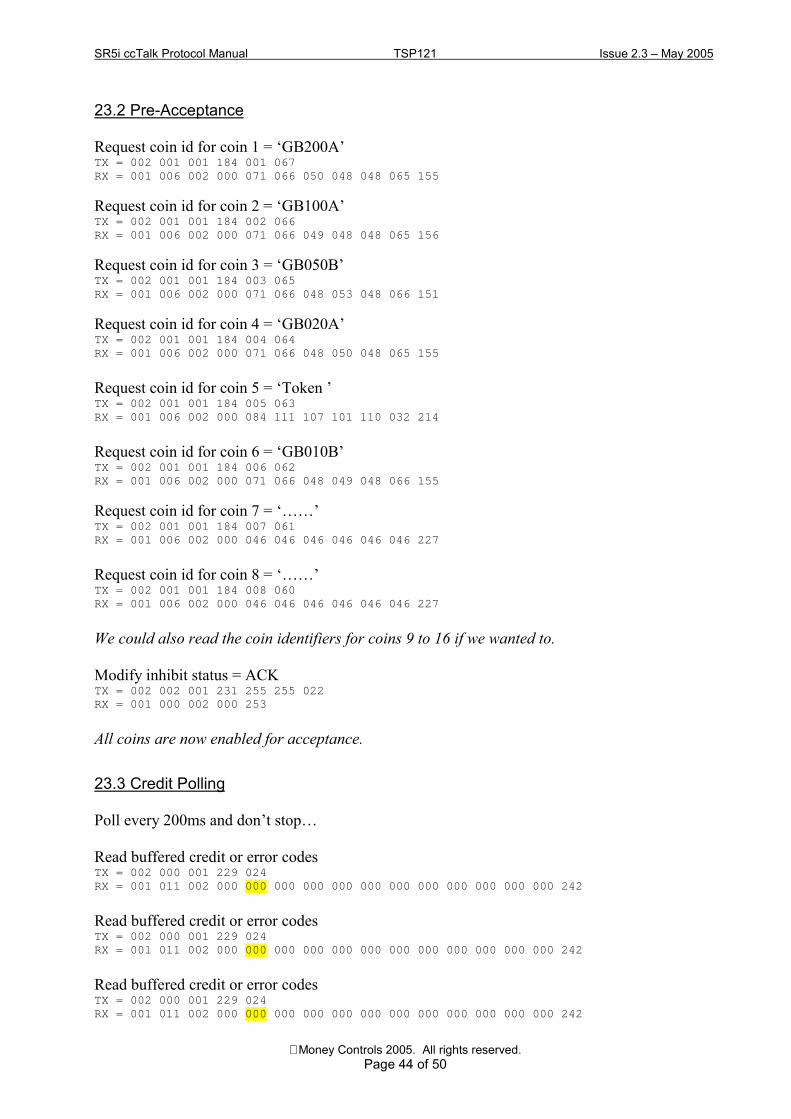
SR5i ccTalk Protocol Manual TSP121 Issue 2.3 � May 2005
Money Controls 2005. All rights reserved.Page 44 of 50
23.2 Pre-Acceptance
Request coin id for coin 1 = �GB200A�TX = 002 001 001 184 001 067RX = 001 006 002 000 071 066 050 048 048 065 155
Request coin id for coin 2 = �GB100A�TX = 002 001 001 184 002 066RX = 001 006 002 000 071 066 049 048 048 065 156
Request coin id for coin 3 = �GB050B�TX = 002 001 001 184 003 065RX = 001 006 002 000 071 066 048 053 048 066 151
Request coin id for coin 4 = �GB020A�TX = 002 001 001 184 004 064RX = 001 006 002 000 071 066 048 050 048 065 155
Request coin id for coin 5 = �Token �TX = 002 001 001 184 005 063RX = 001 006 002 000 084 111 107 101 110 032 214
Request coin id for coin 6 = �GB010B�TX = 002 001 001 184 006 062RX = 001 006 002 000 071 066 048 049 048 066 155
Request coin id for coin 7 = ����TX = 002 001 001 184 007 061RX = 001 006 002 000 046 046 046 046 046 046 227
Request coin id for coin 8 = ����TX = 002 001 001 184 008 060RX = 001 006 002 000 046 046 046 046 046 046 227
We could also read the coin identifiers for coins 9 to 16 if we wanted to.
Modify inhibit status = ACKTX = 002 002 001 231 255 255 022RX = 001 000 002 000 253
All coins are now enabled for acceptance.
23.3 Credit Polling
Poll every 200ms and don�t stop�
Read buffered credit or error codesTX = 002 000 001 229 024RX = 001 011 002 000 000 000 000 000 000 000 000 000 000 000 000 242
Read buffered credit or error codesTX = 002 000 001 229 024RX = 001 011 002 000 000 000 000 000 000 000 000 000 000 000 000 242
Read buffered credit or error codesTX = 002 000 001 229 024RX = 001 011 002 000 000 000 000 000 000 000 000 000 000 000 000 242

SR5i ccTalk Protocol Manual TSP121 Issue 2.3 � May 2005
Money Controls 2005. All rights reserved.Page 45 of 50
Read buffered credit or error codesTX = 002 000 001 229 024RX = 001 011 002 000 000 000 000 000 000 000 000 000 000 000 000 242
Read buffered credit or error codesTX = 002 000 001 229 024RX = 001 011 002 000 001 001 005 000 000 000 000 000 000 000 000 235
Event code has changed from 0 to 1 : Credit, coin 1 to sorter route 5
Read buffered credit or error codesTX = 002 000 001 229 024RX = 001 011 002 000 002 001 005 001 005 000 000 000 000 000 000 228
Event code has changed from 1 to 2 : Credit, coin 1 to sorter route 5
Read buffered credit or error codesTX = 002 000 001 229 024RX = 001 011 002 000 003 005 005 001 005 001 005 000 000 000 000 217
Event code has changed from 2 to 3 : Credit, coin 5 ( = token ) to sorter route 5
Read buffered credit or error codesTX = 002 000 001 229 024RX = 001 011 002 000 004 000 001 005 005 001 005 001 005 000 000 215
Event code has changed from 3 to 4 : Error, Reject coin
Remember that the event code wraps from 255 to 1 as 0 is a special start-up value indicating apower-up or reset has occurred.

SR5i ccTalk Protocol Manual TSP121 Issue 2.3 � May 2005
Money Controls 2005. All rights reserved.Page 46 of 50
23.4 Remote Coin Programming
To replace all coins with new ones�
Remove all coin signatures = ACKTX = 002 001 001 096 245 167RX = 001 000 002 000 253
Begin {
Upload packet data = ACKTX = 002 001 001 096 255 157RX = 001 000 002 000 253
Upload packet data = ACKTX = 002 250 001 096 254067 032 083 082 053 105 032 032 032 032 083 084 068 032 032 032 032 032 048 048048 048 049 026 000 003 225 168 034 086 217 246 119 082 026 062 068 010 084 033166 140 249 214 105 116 129 222 248 042 033 003 111 156 037 002 053 096 251 239097 187 233 046 037 043 160 236 231 170 085 206 072 158 165 049 021 228 011 071193 139 072 141 190 109 096 199 227 005 159 033 095 077 136 049 212 065 049 128036 059 191 036 118 162 199 113 046 221 018 034 238 154 170 250 023 086 066 050005 059 091 074 128 069 049 051 146 253 202 096 223 019 075 156 085 158 032 147220 175 124 184 075 078 208 218 165 152 047 084 221 060 093 032 033 128 012 240053 117 105 023 050 236 193 102 106 227 166 168 017 186 088 064 179 125 008 089145 051 224 167 204 163 030 246 054 121 020 249 027 126 181 008 161 238 083 246199 042 058 067 036 203 158 014 170 207 177 207 234 224 134 106 181 113 232 031211 121 031 104 009 186 219 230 056 142 210 044 186 197 214 255 067 212 000 092032 206 002 020 148 096 086 233 122 ( 249 bytes of data in this example )163RX = 001 000 002 000 253
n x Upload packet data = ACK ( send next data blocks in sequence )
Upload packet data = ACKTX = 002 233 001 096 254029 158 060 155 161 009 248 021 038 198 082 229 102 066 132 003 164 143 041 066187 035 247 245 072 148 089 140 208 052 065 196 131 045 224 253 175 067 243 107217 229 014 215 011 009 053 099 157 187 068 185 246 204 232 117 231 164 013 144008 243 070 208 144 098 027 228 184 108 170 002 175 175 155 213 204 141 015 047087 040 213 003 218 236 119 208 092 009 017 146 234 090 050 131 211 149 084 056205 106 234 018 255 024 115 248 216 150 000 106 181 160 031 242 212 127 063 028041 122 057 117 046 113 219 102 079 139 016 116 250 103 229 230 148 178 167 194075 025 005 122 056 122 017 086 252 195 160 040 243 099 151 231 176 191 010 052148 253 141 224 073 019 234 147 001 226 115 166 186 166 220 083 182 096 164 132014 198 193 204 159 065 049 115 129 058 145 103 179 234 014 171 117 117 161 068164 018 192 126 151 120 097 047 040 115 204 057 230 007 093 237 034 014 104 177176 137 084 025 022 013 021 158 139 165 029 004 ( finally 232 bytes of data in thisexample )165RX = 001 000 002 000 253
End packet upload & program = ACKTX = 002 002 001 096 253 001 157 ( program coin position 1 )RX = 001 000 002 000 253
Wait 200ms
} Loop for all coins

SR5i ccTalk Protocol Manual TSP121 Issue 2.3 � May 2005
Money Controls 2005. All rights reserved.Page 47 of 50
24. Appendix B : Product Differences
24.1 Command Differences
The table below shows the cctalk command differences between all Money Controls 5 inch coinacceptors prior to SR5i
Header Function C435S SR5 SR5R SR5i238 Test output lines # # #237 Read input lines # # #234 Issue guard code # O O O233 Latch output lines # # #205 Request audit information block # O O O198 Counters to EEPROM #185 Modify coin id # # #183 Upload window data # #170 Request base year # # #169 Request address mode # # #162 Modify inhibit and override
registers# # #
137 Switch encryption code #136 Store encryption code #
# = cctalk command implementedO = cctalk command now obsolete
SR5R was a serial-only coin acceptor and so any cctalk commands for testing parallel I/O aremissing.
The �Upload window data� command for programming new coin information is performed withapplication-specific headers on �R� and �i� series coin acceptors.
Encryption is only an option on �i� series coin acceptors.
24.2 Other Differences
ProductData Line pull-up voltage (V)
Coins inhibitedat power-up ?
Implements creditpoll watchdog ?
Inhibitsnon-volatile ?
Master inhibitnon-volatile ?
Sorter overridesnon-volatile ?
Insert / acceptcounters non-volatile ?
C435S12
( tracks supplyvoltage )
No No No Yes No Yes
SR5 5 Yes Yes No Yes No No
SR5R 5 Yes Yes No Yes No No
SR5i 5 Yes Yes No Yes No Yes

SR5i ccTalk Protocol Manual TSP121 Issue 2.3 � May 2005
Money Controls 2005. All rights reserved.Page 48 of 50
C435S returned �Coin Controls Ltd� rather than Money Controls.
C435S supported a dedicated coin-on-string detector as reported back by code 2 of the �Requeststatus� command. SR5i detects coins being pulled backwards using the validation coils but doesnot support �code 2�.
C435S used the PIN mechanism to protect the �Modify master inhibit status� command.
The �base year� for relative date codes on C435S is fixed at 1998 and cannot be read serially.
24.2.1. Token Selection
SR5i supports 6 token groups unlike earlier products which had 12. The sixth token is a �teachand run� token.
Serial Mode Parallel ModeProduct No. of Tokens Teach Position Handheld Rotary Teach Select TeachC435S 12 17 12 F C
SR5 12 17 12 F CSR5R 12 17 12 - -SR5i 6 17 6 or 12 F C
Teach Position : The [ coin position ] to use with cctalk header 202, �Teach mode control� toteach a token.
Handheld : The [ token ] value to use with cctalk header 177, �Handheld function�, to allow theteach token to be accepted.
Rotary Teach : The rotary switch position to teach a token.
Select Teach : The rotary switch position to allow the teach token to be accepted.
24.3 Timing Differences
The inter-byte time ( time from start bit to start bit ) varies slightly between products. SR5ioperates at the maximum theoretical speed for 9600 baud by having each stop bit immediatelyfollowed by a start bit. Software engineers should ensure the receive byte polling loop or receivebyte interrupts can cope with this increased throughput.
Product Inter-byte time( ms )
C435S 2SR5 3SR5R 3SR5i 1

SR5i ccTalk Protocol Manual TSP121 Issue 2.3 � May 2005
Money Controls 2005. All rights reserved.Page 49 of 50
25. Appendix C : Example ROM Checksum TableThe ROM checksum provides a way of verifying the coin acceptor firmware has not beenmodified without the approval of the proper authorities. This checksum represents a �signature�or �hash� of the internal program code but does not include data memories which are likely tochange during the course of a product life such as for counter storage and coin specificationtables.
There are 2 cctalk commands provided on SR5i :-
cctalk header 197, �Calculate ROM checksum�
cctalk header 96:247, �Calculate ROM secure signature�
The first command returns a simple summation of the code bytes. The second takes longer butuses a hashing algorithm and it is possible to pass a 4 byte �seed� to change the outcome of thecommand each time it is used.
If the checksum or signature is being used for code verification then the host machine will needto keep a table of expected return values for each version of software and product type etc.
Remember that the limiting of ROM checksums to certified values precludes the use ofFLASH memory field updates of code and should be used with extreme caution. Mostapplications benefit from a bias towards flexibility rather than security.
Example return data for software version CRS-F1-V1.10
Seed in Hex Result in HexCommands1 s2 s3 s4 r1 r2 r3 r4
197 - - - - 77 5D 35 0196:247 00 00 00 00 B9 8D 0D F196:247 55 55 55 55 EC D8 58 A496:247 AA AA AA AA 13 27 A7 5B96:247 FF FF FF FF 46 72 F2 0E
The results are shown in the order returned by the command[ r1 ] [ r2 ] [ r3 ] [ r4 ]
The table will change completely with each new release of software from Money Controls.

SR5i ccTalk Protocol Manual TSP121 Issue 2.3 � May 2005
Money Controls 2005. All rights reserved.Page 50 of 50
26. Appendix D : Software Issues
None reported.


