GRAVITY WAGON AUGER - grainaugers.com€¢ Remember that auger uses a hand-operated winch that...
30
Part Number: 30388 R2 Revised: 25/5/15 Read this manual before using product. Failure to follow instructions and safety precautions can result in serious injury, death, or property damage. Keep manual for future reference. GRAVITY WAGON AUGER GWA-612 / GWA-615 ASSEMBLY & OPERATION MANUAL
Transcript of GRAVITY WAGON AUGER - grainaugers.com€¢ Remember that auger uses a hand-operated winch that...
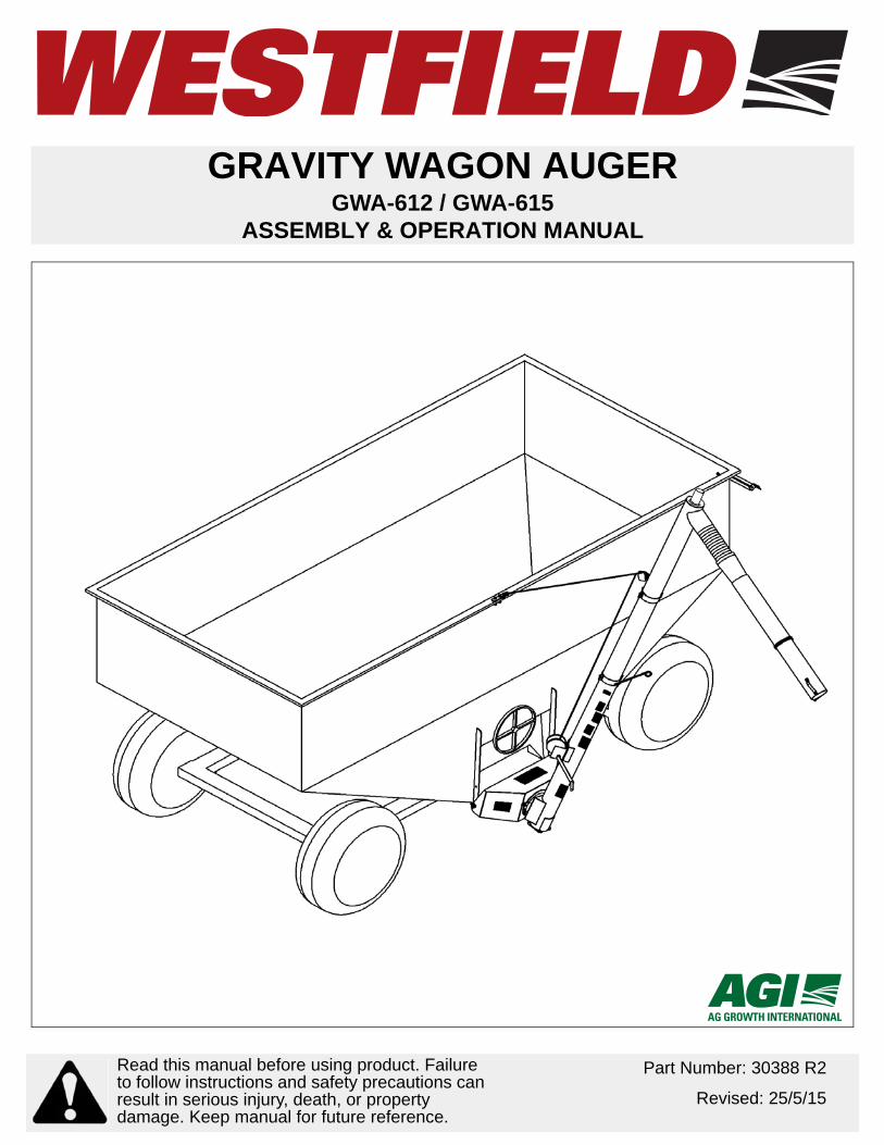
GRAVITY WAGON AUGERGWA-612 / GWA-615
ASSEMBLY & OPERATION MANUAL
Part Number: 30388 R2
Revised: 25/5/15
Read this manual before using product. Failure to follow instructions and safety precautions can result in serious injury, death, or property damage. Keep manual for future reference.

This product has been designed and constructed according to general engineering standardsa. Other local regulations may apply and must be followed by the operator. We strongly recommend that all personnel associated with this equipment be trained in the correct operational and safety procedures required for this product. Periodic reviews of this manual with all employees should be standard practice. For your convenience, we include this sign-off sheet so you can record your periodic reviews.
a. Standards include organizations such as the American Society of Agricultural and Biological Engineers, American National Standards Institute, Canadian Standards Association, International Organization for Standardization, EN Standards, and/or others.
Date Employee Signature Employer Signature
TABLE OF CONTENTS
WESTFIELD - GRAVITY WAGON AUGER GWA-612 / GWA-615
1. Introduction .......................................................................................................................... 3
2. Safety .................................................................................................................................... 52.1. General Safety Information ...................................................................................... 52.2. Assembly Safety....................................................................................................... 62.3. Operational Safety.................................................................................................... 72.4. Transport and Placement Safety.............................................................................. 72.5. Hydraulic Safety ....................................................................................................... 82.6. Maintenance Safety.................................................................................................. 82.7. Safety Decals ........................................................................................................... 9
2.7.1. Decal Installation/Replacement .................................................................. 92.7.2. Safety Decal Locations and Details............................................................ 9
3. Assembly ............................................................................................................................ 113.1. Gravity Wagon Preparation .................................................................................... 113.2. Discharge Hopper .................................................................................................. 123.3. Cable Anchor Bracket ............................................................................................ 123.4. Auger Installation.................................................................................................... 133.5. Winch and Liftcable Installation.............................................................................. 133.6. Transport Bracket................................................................................................... 143.7. Unload Spout & Solenoid Valve ............................................................................. 163.8. Electrical Hookup ................................................................................................... 173.9. Spout Hanger ......................................................................................................... 17
4. Operation ............................................................................................................................ 194.1. Pre-Operational Checklist ...................................................................................... 194.2. Hydraulic Specifications ......................................................................................... 194.3. Start-Up and Break-in............................................................................................. 204.4. Completion / Clean-Up ........................................................................................... 214.5. Transport ................................................................................................................ 21
5. Maintenance & Storage...................................................................................................... 235.1. Maintenance Procedures ....................................................................................... 235.2. Storage Procedures ............................................................................................... 23
6. Troubleshooting ................................................................................................................. 25
Warranty.................................................................................................................................. 27
30388 R2 1

WESTFIELD - GRAVITY WAGON AUGER
GWA-612 / GWA-615
2 30388 R2
WESTFIELD - GRAVITY WAGON AUGER 1. INTRODUCTION
GWA-612 / GWA-615
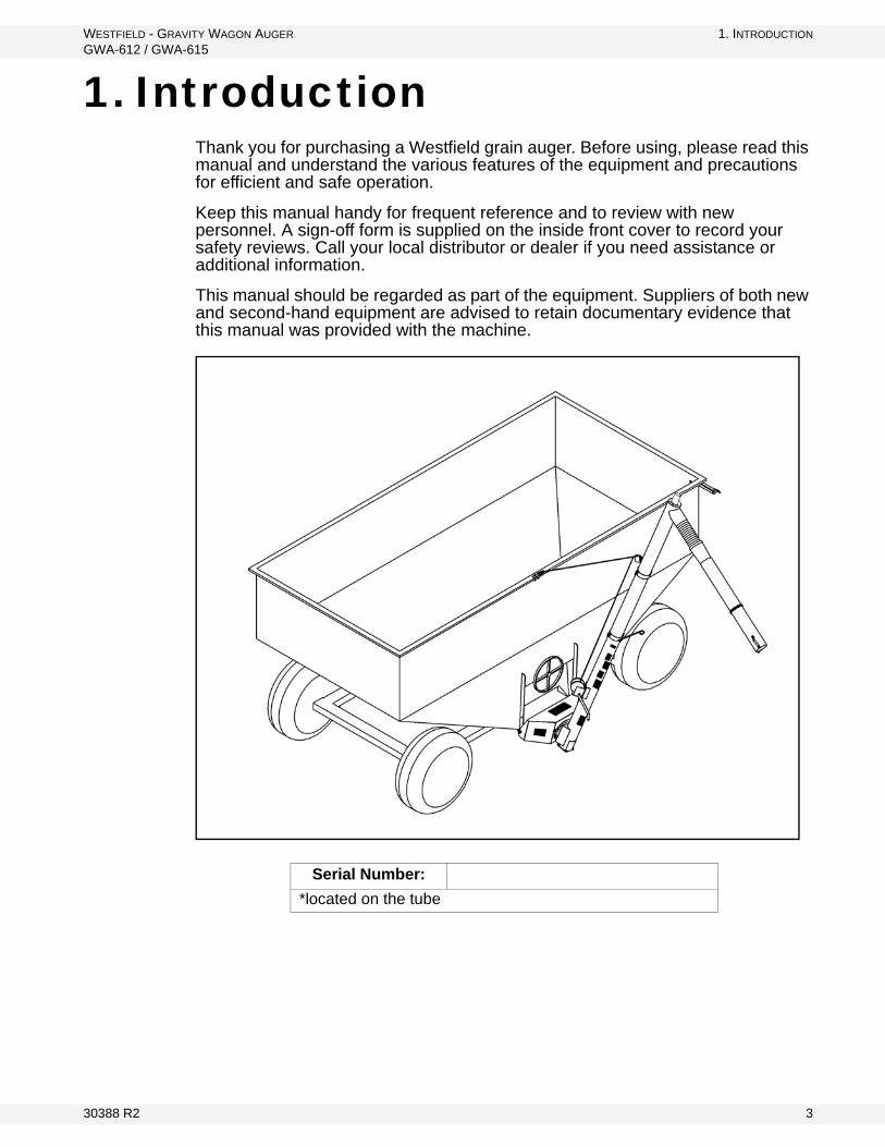
1. IntroductionThank you for purchasing a Westfield grain auger. Before using, please read this manual and understand the various features of the equipment and precautions for efficient and safe operation.
Keep this manual handy for frequent reference and to review with new personnel. A sign-off form is supplied on the inside front cover to record your safety reviews. Call your local distributor or dealer if you need assistance or additional information.
This manual should be regarded as part of the equipment. Suppliers of both new and second-hand equipment are advised to retain documentary evidence that this manual was provided with the machine.
Serial Number:
*located on the tube
30388 R2 3

1. INTRODUCTION WESTFIELD - GRAVITY WAGON AUGER
GWA-612 / GWA-615
4 30388 R2

WESTFIELD - GRAVITY WAGON AUGER 2. SAFETY
GWA-612 / GWA-615 2.1. GENERAL SAFETY INFORMATION
2. Safety2.1. GENERAL SAFETY INFORMATION
The Safety Alert symbol identifies important safety messages on the product and in the manual. When you see this symbol, be alert to the possibility of personal injury or death. Follow the instructions in the safety messages.
Why is SAFETY important?
• Accidents disable and kill.• Accidents cost.• Accidents can be avoided.
SIGNAL WORDS: Note the use of the signal words DANGER, WARNING, CAUTION, and NOTICE with the safety messages. The appropriate signal word for each message has been selected using the definitions below as a guideline.
DANGER
Indicates an imminently hazardous situation that, if not avoided, will result in serious injury or death.
WARNING
Indicates a hazardous situation that, if not avoided, could result in serious injury or death.
CAUTION
Indicates a hazardous situation that, if not avoided, may result in minor or moderate injury.
NOTICE
Indicates a potentially hazardous situation that, if not avoided, may result in property damage.
30388 R2 5
2. SAFETY WESTFIELD - GRAVITY WAGON AUGER
2.2. ASSEMBLY SAFETY GWA-612 / GWA-615
YOU are responsible for the SAFE use and maintenance of your equipment. YOU must ensure that you and anyone else who is going to work around the equipment understands all procedures and related SAFETY information contained in this manual.
Remember, YOU are the key to safety. Good safety practices not only protect you, but also the people around you. Make these practices a working part of your safety program.
Important: Below are general instructions that apply to all safety practices. Any instructions specific to a certain safety practice (e.g., Operational Safety), can be found in the appropriate section. Always read the complete instructional sections and not just these safety summaries before doing anything with the equipment.
• It is the equipment owner, operator, and maintenance personnel's responsi-bility to read and understand ALL safety instructions, safety decals, and man-uals and follow them when assembling, operating, or maintaining the equipment. All accidents can be avoided.
• Equipment owners must give instructions and review the information initially and annually with all personnel before allowing them to operate this product. Untrained users/operators expose themselves and bystanders to possible serious injury or death.
• Use this equipment for its intended purposes only.• Do not modify the equipment in any way without written permission from the
manufacturer. Unauthorized modification may impair the function and/or safety, and could affect the life of the equipment. Any unauthorized modifica-tion of the equipment voids the warranty.
• Do not allow any unauthorized person in the work area.
2.2. ASSEMBLY SAFETY
• Read and understand the assembly instructions to get to know the sub-assemblies and hardware that make up the equipment before proceeding to assemble the product.
• Do not take chances with safety. The components are large, heavy, and can be hard to handle. Always use the proper tools, stands, jacks, and hoists for the job.
• Always have two or more people assembling the equipment. Because of the weight, do not attempt assembly alone.
6 30388 R2
WESTFIELD - GRAVITY WAGON AUGER 2. SAFETY
GWA-612 / GWA-615 2.3. OPERATIONAL SAFETY
2.3. OPERATIONAL SAFETY
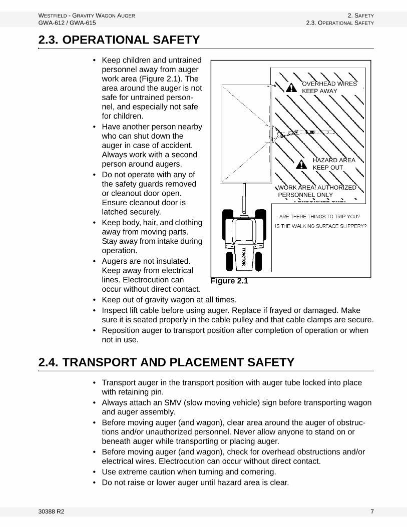
• Keep children and untrained personnel away from auger work area (Figure 2.1). The area around the auger is not safe for untrained person-nel, and especially not safe for children.
• Have another person nearby who can shut down the auger in case of accident. Always work with a second person around augers.
• Do not operate with any of the safety guards removed or cleanout door open. Ensure cleanout door is latched securely.
• Keep body, hair, and clothing away from moving parts. Stay away from intake during operation.
• Augers are not insulated. Keep away from electrical lines. Electrocution can occur without direct contact.
• Keep out of gravity wagon at all times.• Inspect lift cable before using auger. Replace if frayed or damaged. Make
sure it is seated properly in the cable pulley and that cable clamps are secure.• Reposition auger to transport position after completion of operation or when
not in use.
2.4. TRANSPORT AND PLACEMENT SAFETY
• Transport auger in the transport position with auger tube locked into place with retaining pin.
• Always attach an SMV (slow moving vehicle) sign before transporting wagon and auger assembly.
• Before moving auger (and wagon), clear area around the auger of obstruc-tions and/or unauthorized personnel. Never allow anyone to stand on or beneath auger while transporting or placing auger.
• Before moving auger (and wagon), check for overhead obstructions and/or electrical wires. Electrocution can occur without direct contact.
• Use extreme caution when turning and cornering.• Do not raise or lower auger until hazard area is clear.
Figure 2.1
OVERHEAD WIRESKEEP AWAY
HAZARD AREAKEEP OUT
WORK AREA! AUTHORIZED PERSONNEL ONLY
30388 R2 7
2. SAFETY WESTFIELD - GRAVITY WAGON AUGER
2.5. HYDRAULIC SAFETY GWA-612 / GWA-615
• When lowering auger, never continue to turn winch handle counterclockwise if the cable does not keep moving out under load. This will disengage the brake mechanism and will create an unsafe condition, which generally indi-cates that the cable pulley is stuck. Also, too much slack in cable could allow auger to drop suddenly. To correct the problem, winch in the slack cable and correct the sticking cable pulley.
• The winch must make a clicking sound when raising auger. If clicking sound stops, retain grip on handle, lower auger fully, and repair winch.
• After lowering auger, turn winch handle clockwise 2 clicks to lock winch brake.
• The winch is designed for manual operation only.• Always keep a minimum of three cable wraps on winch drum.• Ensure auger is empty and clear area before raising or lowering.• Remember that auger uses a hand-operated winch that automatically locks
into position. Ensure that winch is locked before operating.• Do not get on or beneath auger when raising or lowering auger tube, or when
auger is in transport position.• When raising or lowering the tube, be aware of weight shift. If tube is allowed
to drop, it will result in damage to tube and/or personal injury. Keep firm grip on winch handle.
2.5. HYDRAULIC SAFETY
• Wear proper hand and face protection when searching for hydraulic leaks. Escaping fluid under pressure can penetrate the skin, causing serious injury like gangrene. In case of accident, see a doctor immediately.
• Do not disconnect hydraulic couplers when hydraulic system is pressurized. For the correct procedure, consult this manual or your tractor manual.
• Relieve pressure before unhooking hydraulic lines.• Inspect hydraulic fittings and hoses for damage on a daily basis. Repair if
damaged.• Ensure that the hydraulic line is properly connected and secure.• Keep hydraulic line away from moving parts.• Clean connections before connecting to equipment.
2.6. MAINTENANCE SAFETY
• Shut down and lock out all power before attempting maintenance of any kind. If applicable, disconnect PTO driveline from tractor or hydraulic hoses on units with hydraulic drive hoppers.
• After maintenance is complete, replace and secure all safety guards and safety devices, and if applicable, service doors and cleanout covers.
• Support auger tube before attempting maintenance on the discharge hopper. If possible, auger should be lowered to the ground.
• Use only genuine Westfield replacement parts or equivalent. Replacement parts such as intake guards, pulley guards, PTO driveline shields, winches,
8 30388 R2
WESTFIELD - GRAVITY WAGON AUGER 2. SAFETY
GWA-612 / GWA-615 2.7. SAFETY DECALS
and lift cables must meet ASAE standards or serious injury may result. Use of unauthorized parts will void warranty. If in doubt, contact Westfield or your Westfield dealer. Do not modify any auger components.
2.7. SAFETY DECALS
• Keep safety decals clean and legible at all times.• Replace safety decals that are missing or have become illegible. See decal
location figures that follow.• Replaced parts must display the same decal(s) as the original part.• Replacement safety decals are available free of charge from your distributor,
dealer, or factory.
2.7.1. DECAL INSTALLATION/REPLACEMENT
1. Decal area must be clean and dry, with a temperature above 50°F (10°C).2. Decide on the exact position before you remove the backing paper.3. Align the decal over the specified area and carefully press the small portion
with the exposed sticky backing in place.4. Slowly peel back the remaining paper and carefully smooth the remaining
portion of the decal in place.5. Small air pockets can be pierced with a pin and smoothed out using the sign
backing paper.
2.7.2. SAFETY DECAL LOCATIONS AND DETAILS
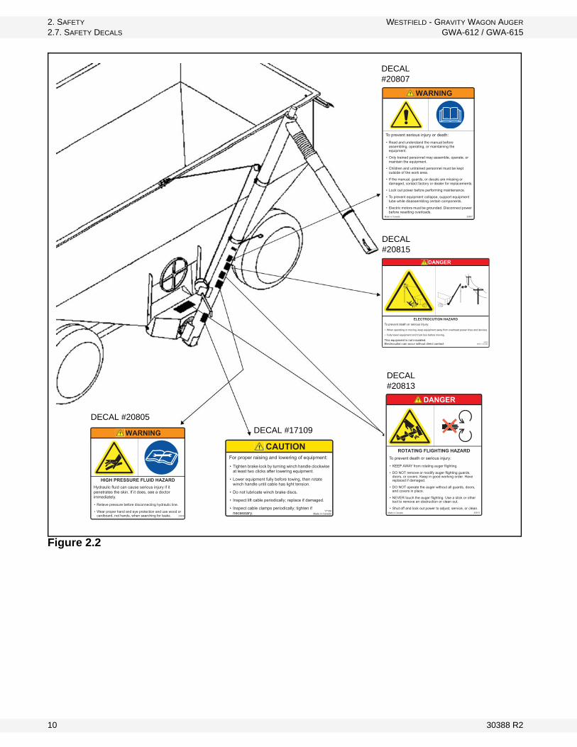
Replicas of the safety decals that are attached to the equipment and their messages are shown in the figure(s) that follow. Safe operation of the equipment requires that you familiarize yourself with the various safety decals and the areas or particular functions that the decals apply to, as well as the safety precautions that must be taken to avoid serious injury, death, or damage. Note: Please review the decals shown. If your auger does not have these decals, they are available upon request. Please specify which decals you need.
* Westfield reserves the right to update safety decals without notice. Safety decals may not be exactly as shown.
30388 R2 9
2. SAFETY WESTFIELD - GRAVITY WAGON AUGER
2.7. SAFETY DECALS GWA-612 / GWA-615
Figure 2.2
WARNING
To prevent serious injury or death:
• Read and understand the manual before assembling, operating, or maintaining the equipment.
• Only trained personnel may assemble, operate, or maintain the equipment.
• Children and untrained personnel must be kept outside of the work area.
• If the manual, guards, or decals are missing or damaged, contact factory or dealer for replacements.
• Lock out power before performing maintenance.
• To prevent equipment collapse, support equipment tube while disassembling certain components.
• Electric motors must be grounded. Disconnect power before resetting overloads.
Made in Canada 20807
CAUTIONFor proper raising and lowering of equipment:
• Tighten brake lock by turning winch handle clockwise at least two clicks after lowering equipment.
• Lower equipment fully before towing, then rotate winch handle until cable has light tension.
• Do not lubricate winch brake discs.
• Inspect lift cable periodically; replace if damaged.
• Inspect cable clamps periodically; tighten if necessary. 17109
Made in Canada
DECAL #20807
DECAL #20815
DECAL #20813
DECAL #20805
DECAL #17109
DANGER
ELECTROCUTION HAZARDTo prevent death or serious injury:
• When operating or moving, keep equipment away from overhead power lines and devices.
• Fully lower equipment and truck box before moving.
This equipment is not insulated.Electrocution can occur without direct contact.
20815Made in Canada
DANGER
ROTATING FLIGHTING HAZARDTo prevent death or serious injury:
• KEEP AWAY from rotating auger flighting.
• DO NOT remove or modify auger flighting guards, doors, or covers. Keep in good working order. Have replaced if damaged.
• DO NOT operate the auger without all guards, doors, and covers in place.
• NEVER touch the auger flighting. Use a stick or other tool to remove an obstruction or clean out.
• Shut off and lock out power to adjust, service, or clean.Made in Canada 20813
WARNING
HIGH PRESSURE FLUID HAZARDHydraulic fluid can cause serious injury if it penetrates the skin. If it does, see a doctor immediately.
• Relieve pressure before disconnecting hydraulic line.
• Wear proper hand and eye protection and use wood or cardboard, not hands, when searching for leaks. 20805
10 30388 R2
WESTFIELD - GRAVITY WAGON AUGER 3. ASSEMBLY
GWA-612 / GWA-615 3.1. GRAVITY WAGON PREPARATION
3. Assembly
Before beginning assembly, familiarize yourself with all the sub-assemblies and hardware making up the auger. Have all parts on hand and arrange them for easy access. Carry out assembly in a large open area with a level surface.
Important: Always have 2 or more people assembling the equipment. Because of the weight, do not attempt assembly alone.
Augers are available in various combinations. In most cases, the following instructions will apply to all augers. Where the assembly information varies, additional instructions will be included and will be indicated with an arrow.
3.1. GRAVITY WAGON PREPARATION
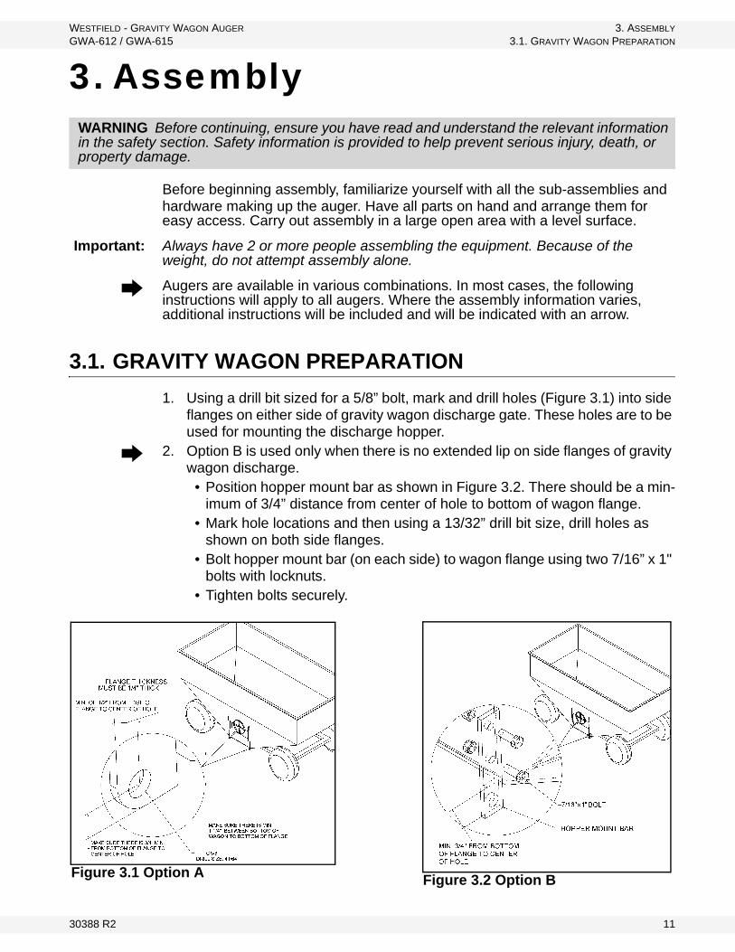
1. Using a drill bit sized for a 5/8” bolt, mark and drill holes (Figure 3.1) into side flanges on either side of gravity wagon discharge gate. These holes are to be used for mounting the discharge hopper.
2. Option B is used only when there is no extended lip on side flanges of gravity wagon discharge.
• Position hopper mount bar as shown in Figure 3.2. There should be a min-imum of 3/4” distance from center of hole to bottom of wagon flange.
• Mark hole locations and then using a 13/32” drill bit size, drill holes as shown on both side flanges.
• Bolt hopper mount bar (on each side) to wagon flange using two 7/16” x 1" bolts with locknuts.
• Tighten bolts securely.
WARNING Before continuing, ensure you have read and understand the relevant information in the safety section. Safety information is provided to help prevent serious injury, death, or property damage.
Figure 3.2 Option BFigure 3.1 Option A
30388 R2 11
3. ASSEMBLY WESTFIELD - GRAVITY WAGON AUGER
3.2. DISCHARGE HOPPER GWA-612 / GWA-615
3.2. DISCHARGE HOPPER
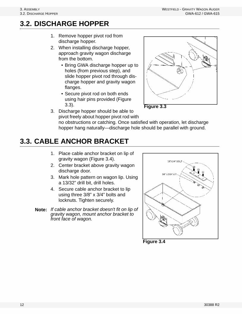
1. Remove hopper pivot rod from discharge hopper.
2. When installing discharge hopper, approach gravity wagon discharge from the bottom.
• Bring GWA discharge hopper up to holes (from previous step), and slide hopper pivot rod through dis-charge hopper and gravity wagon flanges.
• Secure pivot rod on both ends using hair pins provided (Figure 3.3).
3. Discharge hopper should be able to pivot freely about hopper pivot rod with no obstructions or catching. Once satisfied with operation, let discharge hopper hang naturally—discharge hole should be parallel with ground.
3.3. CABLE ANCHOR BRACKET
1. Place cable anchor bracket on lip of gravity wagon (Figure 3.4).
2. Center bracket above gravity wagon discharge door.
3. Mark hole pattern on wagon lip. Using a 13/32” drill bit, drill holes.
4. Secure cable anchor bracket to lip using three 3/8” x 3/4” bolts and locknuts. Tighten securely.
If cable anchor bracket doesn't fit on lip of gravity wagon, mount anchor bracket to front face of wagon.
Figure 3.3
Figure 3.4
Note:
12 30388 R2
WESTFIELD - GRAVITY WAGON AUGER 3. ASSEMBLY
GWA-612 / GWA-615 3.4. AUGER INSTALLATION
3.4. AUGER INSTALLATION
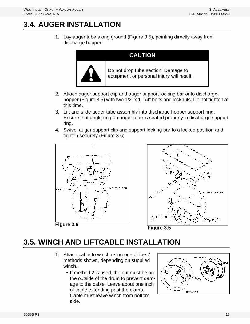
1. Lay auger tube along ground (Figure 3.5), pointing directly away from discharge hopper.
2. Attach auger support clip and auger support locking bar onto discharge hopper (Figure 3.5) with two 1/2” x 1-1/4” bolts and locknuts. Do not tighten at this time.
3. Lift and slide auger tube assembly into discharge hopper support ring. Ensure that angle ring on auger tube is seated properly in discharge support ring.
4. Swivel auger support clip and support locking bar to a locked position and tighten securely (Figure 3.6).
Figure 3.6
3.5. WINCH AND LIFTCABLE INSTALLATION
1. Attach cable to winch using one of the 2 methods shown, depending on supplied winch.
• If method 2 is used, the nut must be on the outside of the drum to prevent dam-age to the cable. Leave about one inch of cable extending past the clamp. Cable must leave winch from bottom side.
CAUTION
Do not drop tube section. Damage to equipment or personal injury will result.
Figure 3.5
30388 R2 13
3. ASSEMBLY WESTFIELD - GRAVITY WAGON AUGER
3.6. TRANSPORT BRACKET GWA-612 / GWA-615
Important: The winch must have a minimum of three wraps of cable on drum when auger is fully lowered (operating position).
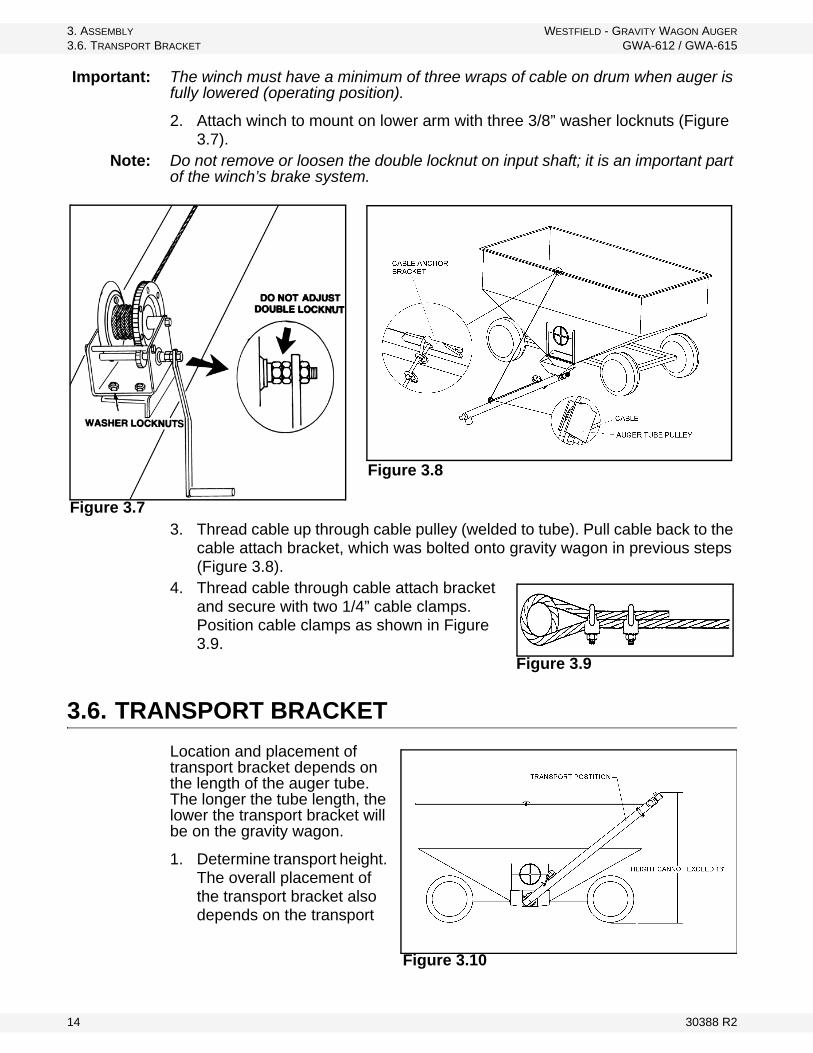
2. Attach winch to mount on lower arm with three 3/8” washer locknuts (Figure 3.7).
Note: Do not remove or loosen the double locknut on input shaft; it is an important part of the winch’s brake system.
3. Thread cable up through cable pulley (welded to tube). Pull cable back to the cable attach bracket, which was bolted onto gravity wagon in previous steps (Figure 3.8).
4. Thread cable through cable attach bracket and secure with two 1/4” cable clamps. Position cable clamps as shown in Figure 3.9.
3.6. TRANSPORT BRACKET
Location and placement of transport bracket depends on the length of the auger tube. The longer the tube length, the lower the transport bracket will be on the gravity wagon.
1. Determine transport height. The overall placement of the transport bracket also depends on the transport
Figure 3.8
Figure 3.7
Figure 3.9
Figure 3.10
14 30388 R2
WESTFIELD - GRAVITY WAGON AUGER 3. ASSEMBLY
GWA-612 / GWA-615 3.6. TRANSPORT BRACKET
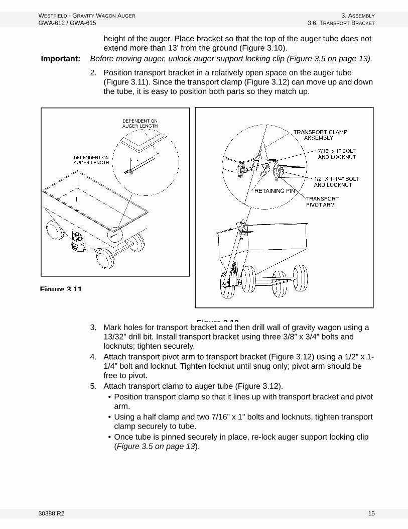
height of the auger. Place bracket so that the top of the auger tube does not extend more than 13' from the ground (Figure 3.10).
Important: Before moving auger, unlock auger support locking clip (Figure 3.5 on page 13).
2. Position transport bracket in a relatively open space on the auger tube (Figure 3.11). Since the transport clamp (Figure 3.12) can move up and down the tube, it is easy to position both parts so they match up.
3. Mark holes for transport bracket and then drill wall of gravity wagon using a 13/32” drill bit. Install transport bracket using three 3/8” x 3/4” bolts and locknuts; tighten securely.
4. Attach transport pivot arm to transport bracket (Figure 3.12) using a 1/2” x 1-1/4” bolt and locknut. Tighten locknut until snug only; pivot arm should be free to pivot.
5. Attach transport clamp to auger tube (Figure 3.12). • Position transport clamp so that it lines up with transport bracket and pivot
arm. • Using a half clamp and two 7/16” x 1" bolts and locknuts, tighten transport
clamp securely to tube. • Once tube is pinned securely in place, re-lock auger support locking clip
(Figure 3.5 on page 13).
Figure 3 12
Figure 3 11
30388 R2 15

3. ASSEMBLY WESTFIELD - GRAVITY WAGON AUGER
3.7. UNLOAD SPOUT & SOLENOID VALVE GWA-612 / GWA-615
3.7. UNLOAD SPOUT & SOLENOID VALVE
1. Slip flexible portion of the telescopic unload spout over auger outlet (Figure 3.13). Secure unload spout with three concave washers and 1/4” x 3/4” self-tapping screws.
2. Remove protective cover plate from hydraulic motor and discard.
3. Ensure o-rings are properly seated in oil ports on hydraulic motor (see Figure 3.14). Remove plastic hole covers from ports of solenoid.
4. Position solenoid with side marked “P” over Port “B” on hydraulic motor (Figure 3.14) and secure solenoid with four 5/16” x 2-3/4” bolts.
Important: To obtain correct rotation on the auger flight, the “P” port on solenoid valve must be located on port “B” of motor (Figure 3.14).
Figure 3.14
5. Tighten nut on coil body after positioning.6. Install a 3/8” hydraulic pressure line from tractor hydraulic system to port
marked “P” on the solenoid, and a 3/8” return line from opposite solenoid port to return port on tractor hydraulic system.
Note: The 3/8” hydraulic hose, pipe, couplers, and 3/8”-18NPTF male fittings must be supplied by customer. Use teflon tape or pipe stick (not supplied) on all hydraulic fittings except where o-rings are used.
Figure 3.13
16 30388 R2
WESTFIELD - GRAVITY WAGON AUGER 3. ASSEMBLY
GWA-612 / GWA-615 3.8. ELECTRICAL HOOKUP
3.8. ELECTRICAL HOOKUP
1. Connect either of the two wires on solenoid to one of the wires on the wiring harness (supplied), then cover connection with electrical tape.
Note: The other wire on the solenoid is the ground wire. The solenoid must be properly grounded: connect a ground wire from the wagon frame to the other wire on the solenoid. Make certain the wire-connecting areas are free of paint, oil, and dirt.
2. Leaving some slack at the solenoid, route the wiring harness down along the down spout.
3. Mount ON/OFF switch to the pre-drilled holes near the telescopic unload spout handle with two 1/4” x 1/2” bolts and whiznuts.
4. Fully extend telescoping unload spout and secure the wiring harness along spout with nylon ties.
Note: Leave some slack in the wiring harness at the flexible portion of the unload spout.
5. Run a 5 amp fused power wire (not supplied) from tractor power to the loose wire on wiring harness. Cover connection with electrical tape.
3.9. SPOUT HANGER
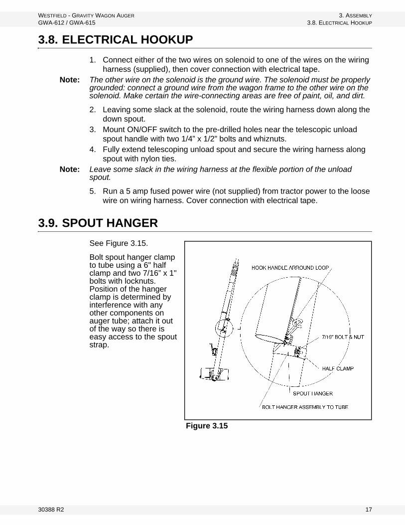
See Figure 3.15.
Bolt spout hanger clamp to tube using a 6" half clamp and two 7/16” x 1" bolts with locknuts. Position of the hanger clamp is determined by interference with any other components on auger tube; attach it out of the way so there is easy access to the spout strap.
Figure 3.15
30388 R2 17

3. ASSEMBLY WESTFIELD - GRAVITY WAGON AUGER
3.9. SPOUT HANGER GWA-612 / GWA-615
18 30388 R2
WESTFIELD - GRAVITY WAGON AUGER 4. OPERATION
GWA-612 / GWA-615 4.1. PRE-OPERATIONAL CHECKLIST
4. Operation
4.1. PRE-OPERATIONAL CHECKLIST
Before operating auger each time, the operator must confirm the following:
• All fasteners are secure as per assembly instructions.• Cable clamps are secure.• Cable is not frayed, damaged, or kinked.• Discharge hopper mount rod is not bent or cracked.• Discharge hopper is securely mounted on mount rod with retaining pin in
place.• Intake area and discharge spout are free of obstructions.• Cleanout cover is closed and secured with retaining pins in place and
secure.• Hydraulic hoses are in good condition.• Hydraulic connections are in place and secure.• Proper maintenance has been performed.
4.2. HYDRAULIC SPECIFICATIONS
• Required operating pressure is 1400 psi (13, 443 kPa) at a maximum flow rate of 12 gpm.
• Hose requirement: 3/8” diameter hydraulic hose.• Pulsar 109-06-3/8” - 3000 psi WPSAE 100R17-30-99) complete with 3/8”
NPTF male fitting.• Length of hose is dependent on distance from wagon discharge to tractor
hydraulics.
WARNING Before continuing, ensure you have read and understand the relevant information in the safety section. Safety information is provided to help prevent serious injury, death, or property damage.
CAUTION
Do not drop tube, there will be damage to the tube and serious personal injury. Keep firm grip on winch handle.
30388 R2 19

4. OPERATION WESTFIELD - GRAVITY WAGON AUGER
4.3. START-UP AND BREAK-IN GWA-612 / GWA-615
4.3. START-UP AND BREAK-IN
1. Complete the pre-operational checklist at the start of this section.2. If everything is satisfactory, prepare for a 10 minute operation at half speed.3. Position gravity wagon close to seeding equipment.4. Correctly position the intake hopper.5. Properly connect all hoses. 6. Unlock auger tube from transport bracket.7. To position auger tube, turn winch and physically pull or push tube to the
desired location.8. Position auger tube and telescopic discharge spout to maximize product flow
and dispersion to seeding equipment.9. When desired auger position is obtained, lock auger tube into place by
rotating support ring locking bar to lock position.Important: When starting gravity wagon auger for the first time, be prepared for an
emergency shutdown in case of excessive vibration or noise. Note that the auger may run rough until tube is polished.
10. Start tractor and idle at low rpm. Engage hydraulic flow lever.11. Turn switch on telescopic spout to ON. Check that flighting is engaged and
turning in the right direction.Important: In order to maintain proper grain flow through the discharge spout, hold spout at
no less than 45° to the horizontal during operation. A more shallow angle could plug the downspout, resulting in damage to the equipment.
12. Place telescopic unload spout in collection bin. Do not over-extend spout, as plugging will occur.
13. Gradually begin feeding grain into the discharge hopper. • Make sure that grain is being transported up the tube to discharge end. • Do not overfill the hopper on initial loads, keep feed of grain at about half
capacity. • After auger tube is polished and runs smoothly, proceed to unload at the
full speed of 500 rpm (flight rotation speed) and at full hopper capacity.Important: Always unload auger tube at the end of filling session or before transport mode.
20 30388 R2
WESTFIELD - GRAVITY WAGON AUGER 4. OPERATION
GWA-612 / GWA-615 4.4. COMPLETION / CLEAN-UP
4.4. COMPLETION / CLEAN-UP
After operation, move the auger (along with gravity wagon) to the next work area or to a storage area. The recommended procedure is:
1. Lock out power. 2. Clean entire work area.3. Empty auger. If necessary, manually clean out grain using a piece of wood,
vacuum cleaner, or other tool. Do not use hands.4. Auger can be completely disassembled from wagon or remain locked in
transport position for storage.
4.5. TRANSPORT
Note: Empty auger and lock it in transport position before transporting.
1. Unlock auger tube by rotating auger locking bar to unlocked position.2. Push auger tube towards transport bracket. At the same time, adjust tube
height to match bracket by turning winch handle. 3. Adjust auger tube height until locking pin is positioned inside transport
bracket hole.4. Release tension on cable. Let tube rest in bracket.5. Lock tube into place by inserting hairpin.
WARNING
Do not operate auger if clean-out doors are open or removed.
30388 R2 21

4. OPERATION WESTFIELD - GRAVITY WAGON AUGER
4.5. TRANSPORT GWA-612 / GWA-615
22 30388 R2
WESTFIELD - GRAVITY WAGON AUGER 5. MAINTENANCE & STORAGE
GWA-612 / GWA-615 5.1. MAINTENANCE PROCEDURES
5. Maintenance & Storage
Proper maintenance habits on the gravity wagon auger mean a longer life, better efficiency, and safer operation.
5.1. MAINTENANCE PROCEDURES
We recommend the following steps for the general maintenance of the auger.
1. Observe the “Pre-Operational Checklist” on page 19 on a daily basis when auger is in use.
2. Check all operating, lifting, and transport components. Replace damaged or worn parts before using auger.
Note: To replace a damaged part, refer to “Assembly” on page 11.
5.2. STORAGE PROCEDURES
To protect auger in storage during the off-season, we suggest the following:
1. Remove all residual material from the hopper and tube.2. Lock auger in transport position. 3. Release tension in cable, disconnect hoses, and plug up hydraulic openings. 4. Inspect auger for damage and note any repairs required. Order replacement
parts from your dealer.
WARNING Before continuing, ensure you have read and understand the relevant information in the safety section. Safety information is provided to help prevent serious injury, death, or property damage.
30388 R2 23

5. MAINTENANCE & STORAGE WESTFIELD - GRAVITY WAGON AUGER
5.2. STORAGE PROCEDURES GWA-612 / GWA-615
24 30388 R2

WESTFIELD - GRAVITY WAGON AUGER 6. TROUBLESHOOTING
GWA-612 / GWA-615
6. TroubleshootingThe Gravity Wagon Auger uses steel (or brush) flighting inside a steel tubing to convey material from the gravity wagon to other devices. It is a simple and reliable system that requires minimal maintenance.
In the following section, we have listed some causes and solutions to some of the problems you may encounter in the field.
If you encounter a problem that is difficult to solve, even after having read through this troubleshooting section, please call your local Westfield dealer or distributor. Before you call, please have this manual and the serial number from your machine ready.
Problem Cause Solutions
Auger runs too slow.
Tractor engine running too slow. Increase engine speed.Tractor pump not producing required flow and pressure.
Check tractor pump capacity and correct.
Hydraulic auger motor worn. Repair or replace.Solenoid mounted wrong. Mount solenoid to motor as per instructions.Hydraulic hose too small. Replace with correct hose (3/8”).
Auger won’t run
Auger jammed.Shut off and lock out power. Open cleanout doors and remove excess seed or fertilizer. Make sure discharge spout is clear.
No hydraulic pressure to motor.Check for correct attachment for hydraulic hoses and routing.
No power to solenoid.Correct or replace: burned fuse, poor ground-sole-noid to wagon frame, wire connections at solenoid or control switch broken.
Burned out solenoid. Replace solenoid.Ports between hydraulic motor and solenoid blocked.
Remove solenoid and clean out obstruction.
Solenoid mounted wrong. Mount solenoid as per instructions.Poor grounding. Properly ground solenoid to wagon frame or tractor.
Oil leaking at motor and sole-noid connec-tion.
Solenoid bolts loose. Tighten bolts.O-rings damaged or not installed properly.
Remove solenoid and check that o-rings are prop-erly installed. Replace if damaged.
Auger creeps when spout switch is shut off.
Oil flow (gpm) is too high.Decrease oil flow (not pressure) to hydraulic motor with use of flow control valve. Flow must not exceed 12 gpm.
Solenoid won't function.
Poor ground. Attach ground wire from solenoid to wagon frame.Solenoid mounted wrong. Mount solenoid to motor as per instructions.
30388 R2 25

6. TROUBLESHOOTING WESTFIELD - GRAVITY WAGON AUGER
GWA-612 / GWA-615
26 30388 R2

WARRANTYWestfield Industries Ltd. warrants products of its manufacture against defects in materials or workmanship under normal and reasonable use for a period of one year after date of delivery to the original purchaser.
Our obligation under this warranty is limited to repairing, replacing, or refunding defective part or parts which shall be returned to a distributor or a dealer of our Company, or to our factory, with transportation charges prepaid. This warranty does not obligate Westfield Industries Ltd. to bear the cost of labor in replacing defective parts. Any defects must be reported to the Company before the end of the one year period.
This warranty shall not apply to equipment which has been altered, improperly assembled, improperly maintained, or improperly repaired so as to adversely affect its performance. Westfield Industries Ltd. makes no express warranty of any character with respect to parts not of its manufacture.
The foregoing is in lieu of all other warranties, expressed or implied, including any warranties that extend beyond the description of the product, and the IMPLIED WARRANTY of MERCHANTABILITY is expressly excluded.
WESTFIELD INDUSTRIES LTD.
ROSENORT, MANITOBA
CANADA
R0G 1W0

P.O. Box 39
Rosenort, Manitoba, R0G 1W0, CANADA
PHONE: (866) 467-7207 (Canada & USA) or (204) 746-2396
FAX: (866) 768-4852
WEB: www.grainaugers.com
EMAIL: [email protected]
Westfield is part of the Ag Growth International group
© Ag Growth International Inc. 2015
Printed in Canada