GRANT AGREEMENT 671458 Swiss (SERI) Contract No 15.0252 ...
30
GRANT AGREEMENT 671458 Swiss (SERI) Contract No 15.0252 STATUS: FINAL PUBLIC
Transcript of GRANT AGREEMENT 671458 Swiss (SERI) Contract No 15.0252 ...

GRANT AGREEMENT 671458
Swiss (SERI) Contract No 15.0252
STATUS: FINAL
PUBLIC

D2.1. Assessment of the regulatory framework and end-user/customer
ELYNTEGRATION. FCH-JU Grant Agreement 671458. SERI Contract number 15.0252 2
This project has received funding from the Fuel Cells and Hydrogen 2 Joint Undertaking under
grant agreement No 671458. This Joint Undertaking receives support from the European Union’s
Horizon 2020 research and innovation programme and Spain, Belgium, Germany, Switzerland.
This work is supported by the Swiss State Secretariat for Education, Research and Innovation
(SERI) under contract number 15.0252. The contents of this document are provided “AS IS”. It
reflects only the authors’ view and the JU is not responsible for any use that may be made of the
information it contains.
Kevin Münch1, Patrick Larscheid1, Lara Lück1, Rubén Canalejas2, Jesús Simón2, Alfonso
Arnedo2 , Vanesa Gil2
1 RWTH Aachen University, Institute of Power Systems and Power Economics, Germany
2 Fundación para el Desarrollo de Nuevas Tecnologías del Hidrógeno en Aragón, Spain
Author printed in bold is the contact person/corresponding author
February, 2016

D2.1. Assessment of the regulatory framework and end-user/customer
ELYNTEGRATION. FCH-JU Grant Agreement 671458. SERI Contract number 15.0252 3
Content
1 Executive Summary ............................................................................................5
2 Objectives..........................................................................................................6
2.1 Grid Connection .............................................................................................7
2.2 Regulatory Framework ...................................................................................7
2.3 Grid Services ..................................................................................................7
3 Description of work ............................................................................................8
3.1 Grid Connection .............................................................................................8
3.1.1 Voltage level ...........................................................................................8
3.1.2 Grid disturbances in general ....................................................................9
3.1.3 Rapid Voltage Changes ............................................................................9
3.1.4 Flicker .................................................................................................. 10
3.1.5 Harmonics ............................................................................................ 10
3.1.6 Voltage phase Unbalances ..................................................................... 11
3.1.7 Commutation Notches .......................................................................... 11
3.1.8 Audio-Frequency Centralised Ripple-Control........................................... 11
3.1.9 Grid Voltage Drop ................................................................................. 12
3.1.10 Reactive Power Compensation .............................................................. 12
3.1.11 Interim Conclusion................................................................................ 12
3.2 Regulatory Framework ................................................................................. 13
3.2.1 Composition of Consumer Price of Electricity.......................................... 13
3.2.2 Use of System Charges .......................................................................... 16
3.2.3 RES Subsidy Surcharge........................................................................... 17
3.2.4 Electricity Tax........................................................................................ 17
3.2.5 Interim Conclusion ................................................................................ 17
3.3 Grid services ................................................................................................ 18
3.3.1 Control Reserve .................................................................................... 18
3.3.2 Automatic Frequency Restoration Reserve ............................................. 22
3.3.3 Manual Frequency Restoration Reserve ................................................. 24
3.3.4 Distribution Grid Services ...................................................................... 25
3.3.5 Interim Conclusion ................................................................................ 25
4 Conclusions ..................................................................................................... 27

D2.1. Assessment of the regulatory framework and end-user/customer
ELYNTEGRATION. FCH-JU Grant Agreement 671458. SERI Contract number 15.0252 4
5 REFERENCES .................................................................................................... 28
Figures
Figure 1. Schematic display of harmonic distortion of phase voltage ............................ 10
Figure 2. Schematic display of commutation notches .................................................. 11
Figure 3. Electricity price elements for end users ........................................................ 13
Figure 4: Average electricity prices for domestic consumers ........................................ 14
Figure 5: Average electricity prices for industrial consumers (20 MWh – 500 MWh) ..... 15
Figure 6: Average electricity prices for industrial consumers (20 GWh – 70 GWh) ......... 15
Figure 7. Use of system charges for end users............................................................. 16
Figure 8. Consecutive activation of different types of control reserve .......................... 19
Figure 9. Ramping protocol for aFRR in Germany [18] ................................................. 23
Figure 10. Accepted delay time for automatic Restoration Reserve in Germany............ 23
Figure 11. Operational protocol for aFRR in Germany [18]........................................... 25
Tables
Table 1. Example of DSO classification of connection power ranges to voltage level .......9
Table 2. Demand response and activation time for control reserve in Europe ............... 20
Table 3. Technical requirements for aFRR in Germany................................................. 22
Table 4. Technical requirements for mFRR in Germany [18]......................................... 24

D2.1. Assessment of the regulatory framework and end-user/customer
ELYNTEGRATION. FCH-JU Grant Agreement 671458. SERI Contract number 15.0252 5
1 EXECUTIVE SUMMARY
The research and innovation project “Grid Integrated Multi Megawatt High Pressure
Alkaline Electrolysers for Energy Applications” (ELYntegration) is focused on the design and
engineering of a robust, flexible, efficient and cost-competitive electrolyser. To meet technical
and economical requirements, a commercial deployment of an electrolyser has to take into
account a lot of steps. This deliverable focused on the clarification of the end-user’s
requirements in the areas grid connection, regulatory framework and grid services.
The deliverable shows that the technical requirements of grid disturbances are not to be
seen as critical and solutions for grid disturbance issues are state of the art. Furthermore the
deliverable presents that the national regulatory frameworks affect the price elements.
Therefore, the possible business models have to be investigated in each county individual ly. For
example, in Germany it is necessary to consider possible exemptions for electrolysers from use
of system charges, RES subsidy surcharge and the electricity tax. Finally, the deliverable
investigates if grid services could be a business model for electrolysers. Depending on the
service, the electrolyser design has to consider these additional technical requirements such as
ramping abilities.

D2.1. Assessment of the regulatory framework and end-user/customer
ELYNTEGRATION. FCH-JU Grant Agreement 671458. SERI Contract number 15.0252 6
2 OBJECTIVES
The research and innovation project “Grid Integrated Multi Megawatt High Pressure
Alkaline Electrolysers for Energy Applications” is focused on the design and engineering of a
robust, flexible, efficient and cost-competitive single stack Multi Megawatt High Pressure
Alkaline Water Electrolysis (hereafter referred to as electrolyser). To meet technical and
economical requirements, a commercial deployment of an electrolyser has to take into account
following key steps:
Clarify the end-user requirements and potential business models
Define technical specifications of future electrolysers so that its exploitation can
provide financial incomes
Reduce electrolyser costs of Ownership and achieve highly competitive CAPEX
This deliverable focuses the first part of the first point: The Assessment of the regulatory
framework and end-user/customer. Even the analysis of this part represents a complex
challenge. The second part of the first point and the other points are later edited by other work
packages of this project and published in future Deliverables.
From the simple perspective from an electricity grid, an electrolyser is a customer who
uses the grid to consume electricity. For the connection the grid operator defines a technical
framework.
Furthermore, the European Electricity Markets are liberalised. This means that the
electricity networks have to be independent companies. Due to the natural monopoly of
electricity grids, they are regulated by government agencies. Therefore, the connection tariffs
for electrolysers are affected by the regulatory framework. This affects in further steps the
potential of possible business models. Thus, this deliverable considers the technical framework
and the regulatory framework.
The electricity world is more and more dominated by intermittent renewable energy
sources (wind and solar). Today scenarios with a surplus of electricity generation rarely occur,
but in the near future and distant future the probability for these scenarios increases. Therefore,
the electricity grid needs additional consumption or Energy Storage Systems (ESS). For example,
an electrolyser could provide this consumption as a grid service. Also other grid services are
imaginable. As the grid operators have to pay for grid services, the technical requirements to
provide grid services are also important for the evaluation of potential business models.
Therefore, this deliverable works on three areas and has to formulate the associated
objectives:
Grid connection
Regulatory framework
Grid services

D2.1. Assessment of the regulatory framework and end-user/customer
ELYNTEGRATION. FCH-JU Grant Agreement 671458. SERI Contract number 15.0252 7
2.1 Grid Connection
The first objective is the grid connection. This analyses the standards for electricity grid
connections. The first important question is of course where to connect an electrolyser with a
consumption of almost 10 MW electricity. Which voltage level is necessary or which voltage
level is expected? As the voltage level is fixed, the deliverable analyses the technical framework.
Especially the question, what grid disturbances by customer facilities have to be considered?
2.2 Regulatory Framework
The regulatory framework influences the connection tariffs. For example the grid charges
or subsidies for renewable energies or ESS could be different from country to country, or even
inexistent in the case of the subsidies. Therefore, the main question is, which cost has to be
expected in which country? The answer to this question is very important for the identification
of business models in the next steps of the project.
2.3 Grid Services
As grid services could be useful or necessary for grid operators in the near or distant
future, electrolyser could participate and provide some kind of services. As this also could be a
potential business model, the deliverable analyses the technical requirements for grid services.
Especially the question, which extra requirements have to be met to provide grid services as an
additional business model?

D2.1. Assessment of the regulatory framework and end-user/customer
ELYNTEGRATION. FCH-JU Grant Agreement 671458. SERI Contract number 15.0252 8
3 DESCRIPTION OF WORK
As chapter 2 introduces, this deliverable has three objectives:
Grid connection
Regulatory framework
Grid services
Therefore, this chapter analyses the three objectives.
3.1 Grid Connection
When assessing all requirements needed to pave the way for the future deployment of
electrolysers, an essential part are technical requirements that electrolysers need to fulfil for
grid connection. At first, it needs to be determined to which voltage leve l an electrolyser of
several megawatt is most likely to be connected. This enables to identify which kind of system
operator is to be contacted for grid connection and thus which technical requirements apply.
Technical requirements for end users are mainly connected to limitations on the effect of grid
disturbances. After a short overview on the relevant grid codes, end user requirements for
reducing grid disturbances like rapid voltage changes, flicker, harmonics, voltage phase
unbalances, commutation notches, audio-frequency centralised ripple control and grid voltage
drops are addressed. For each grid disturbance, an assessment on its relevance for the grid
connection of electrolysers is undertaken and it is analysed to what extent these requirements
might impose critical challenges for grid connection. Appropriate countermeasures are
presented. Finally, reactive power compensation requirements are depicted.
3.1.1 Voltage level
The voltage level to which the electrolyser is to be connected is essential. Apart from
determining which grid operator has to be approached for a request of grid connection, it
defines which technical requirements for grid connection apply. The costs for grid connection
and use of system charges are also dependent on the voltage level (see section 3.2.2).
Consequently, the voltage level is relevant for the efficiency of business models.
The grid connection point of a new customer and therefore its voltage level is determined
individually by the grid operator based on the grid impedance at the junction point, the
maximum power and the type of the customer. Table 1 shows reference values for the
connection voltage level in dependence of the maximum power of a customer exemplary for
grid operators Westnetz GmbH and Unión Fenosa Distribución respectively Red Eléctrica de
España (REE). Westnetz GmbH is the largest German distribution grid operator supplying more
than 7 million people with electricity [1] [1]. Unión Fenosa is a Spanish distribution grid operator,
that together with Iberdrola Distribución, Endesa Distribución, HC Energía and E.ON Distribución
España are the main Spanish DSOs that supply electricity to more than 95% of the population.
Red Eléctrica de España is the Spanish transmission grid operator. The other grid operators
within Germany and Spain use similar reference values.
The aim of this project is the development of an electrolyser with a maximum power of
9.2 MW. The electrolyser is therefore to be connected either to the medium voltage grid or

D2.1. Assessment of the regulatory framework and end-user/customer
ELYNTEGRATION. FCH-JU Grant Agreement 671458. SERI Contract number 15.0252 9
directly to a high voltage/medium voltage substation. Therefore, the assessment of grid
connection is concentrated on the medium voltage level in this Deliverable.
Connection voltage level Maximum annual power
Westnetz GmbH Unión Fenosa & REE
Low voltage grid < 85 kVA 50 kVA
Medium voltage/low voltage substation < 200 kVA 50 kVA – 450 kVA
Medium voltage grid 200 kVA – 5.5 MVA 250 kVA – 10 MVA
High voltage/medium voltage substation 3 MVA – 15 MVA 1 MVA – 12 MVA
High voltage grid Individual specification > 10 MVA
Table 1. Example of DSO classification of connection power ranges to voltage level [1] [2]
3.1.2 Grid disturbances in general
Customer facilities impose disturbances on the power system to which they are
connected. In order to limit these disturbances to an appropriate level, grid operators establish
technical requirements. The end user has fulfilled these requirements. Otherwise, the operator
of the customer facility has to take countermeasures.
On European level, the grid codes on electromagnetic compatibility IEC 61000-3-3 [3],
IEC 61000-3-6 [4] and IEC 61000-3-7 [5] formulate emission limits for the connection of
distorting and fluctuating installations to medium and high voltage power systems. National grid
codes are generally aligned with these European grid codes. The guideline “Technical Conditions
for Connection to the medium-voltage network” by the German Association of Energy and
Water Industries (BDEW) is used as a reference for German distribution grid operators [6]. Since
the BDEW guideline is not binding, each grid operator is allowed to adapt the specif ications to
their own needs. Spanish guidelines are defined in case of the distribution grids by the Spanish
distribution grid operators individually. However, their specifications are similar. REE as
transmission grid operator in Spain is responsible for the management of the connexion to the
high voltage grid (400 kV and 220 kV, and 220 kV, 132 kV and 66 kV in the insular grid system).
The guideline for the connection to the high voltage power grid (>220 kV) is the “Guía descriptiva
del procedimiento de conexión a la red” [7].
The following sections depict and analyse the relevant grid whether they are critical for
an electrolyser as a customer facility.
3.1.3 Rapid Voltage Changes
Strong and fast load changes within seconds lead to rapid voltage changes at the
connection point. These often occur during switch-on of large motors, welding sets and electric
arc furnaces. According to German grid codes, the maximum permissible rapid voltage change
is 2 % of the rated voltage [6], within Spain the limit is set to 7 % of the rated voltage [8].

D2.1. Assessment of the regulatory framework and end-user/customer
ELYNTEGRATION. FCH-JU Grant Agreement 671458. SERI Contract number 15.0252 10
Since for electrolysers no strong and fast load changes occur, rapid voltage changes do
not impose critical restrictions for electrolysers. Therefore, the corresponding grid codes for
rapid voltage changes are not relevant for the design of the grid connection of electrolysers.
3.1.4 Flicker
Flicker phenomena are characterised by voltage fluctuations with certain frequencies and
large enough amplitudes leading to visible fluctuating lighting densities for electric lamps. In
order to reduce the impairment of illumination, grid connection codes prescribe limits for
maximum admissible flicker strengths by customer facilities. The flicker strength is defined as a
value that expresses the susceptibility of the human eye for luminosity variation of a 60 W lamp
with tungsten wire as a result of voltage variations.
Since flicker reduction by use of compensating condensers is state of the art, this technical
requirement is not critical for grid connection of electrolysers. When designing the grid
connection for electrolysers, appropriate compensation devices need to be included.
3.1.5 Harmonics
Due to the switching characteristic of power electronic converters, customer facilities
with power electronic equipment inject harmonic currents at the grid connection point inducing
harmonic voltages within the grid. These harmonic voltages are seen at each connection point
of the grid and impair the sinusoidal waveform with the fundamental frequency of 50 Hz.
Figure 1 shows an exemplary voltage waveform impaired by harmonics of third and fifth order.
In order to reduce the impairment of the phase voltages, the grid codes define upper limits for
the harmonic current injection per customer facility.
Figure 1. Schematic display of harmonic distortion of phase voltage
Due to their power electronics interface, electrolysers impose harmonics on the power
system and compliance of harmonic current injection limits need to be observed and assured.
Countermeasures such as higher-pulse switching mode of the voltage source converter based
power electronic interface and appropriate applications filtering the harmonics are available and
state of the art. When planning the grid connection for electrolysers, these countermeasures
need to be considered.
Vo
ltag
e
Time
3rd Harmonic
Vo
ltag
e
Time
Fundamental Frequency
Vo
ltag
e
Time
5th Harmonic
Vo
ltag
e
Time
Resultant Voltage

D2.1. Assessment of the regulatory framework and end-user/customer
ELYNTEGRATION. FCH-JU Grant Agreement 671458. SERI Contract number 15.0252 11
3.1.6 Voltage phase Unbalances
Within a three-phase power system, the voltages of all three phases should ideally be
symmetrical. That means that the voltage of each phase should have the same magnitude and
the angle between two phase voltages should always be 120 degrees. A deviation from these
symmetrical conditions is called voltage phase unbalance.
Voltage phase unbalances are caused by single-phase or asymmetrical three-phase loads.
Typical loads with these characteristics are customer facilities like induction furnaces, arc
furnaces and welding machines. The grid codes define upper limits for the resultant degree of
unbalance by each customer facility.
Since electrolysers with a maximum power consumption of several megawatt are
equipped with a three-phase power electronic connection, voltage phase unbalances are not
critical for the grid connection of electrolysers.
3.1.7 Commutation Notches
Commutation notches are characterized by abrupt and large voltage drops for a fraction
of line frequency cycle. These notches occur for line-commutated converters due to the
switching of its thyristors. During the commutation process all thyristors of both commutating
phases are conducting thus shorting both phase voltages through the line reactance. This results
in abrupt voltage deviations from the sinusoidal waveform of the standard 50 Hz power system
frequency during the commutation intervals. Figure 2 shows schematically the AC voltage of one
phase of a three-phase, full-bridge, six-pulse converter for two line frequency cycles.
Figure 2. Schematic display of commutation notches for a three-phase line-commutated converter topologies [9]
As electrolysers are usually connected to the grid via a voltage source based power
electronic converter, commutation notches do not occur for electrolyser applications. The
corresponding grid codes are therefore only relevant for grid connection of electrolysers if line-
commutated power electronic interfaces are used.
3.1.8 Audio-Frequency Centralised Ripple-Control
Several distribution grid operators within Europe use audio-frequency centralised ripple
control in order to control loads and generating units connected to their grid. One example is
the switching of streetlamps at morning and evening. As communication path, the existing
electricity grid is used. Within this concept, a control signal with a higher-frequency than the
Ph
ase
Vo
ltag
e
Time

D2.1. Assessment of the regulatory framework and end-user/customer
ELYNTEGRATION. FCH-JU Grant Agreement 671458. SERI Contract number 15.0252 12
standard 50 Hz is superimposed. Loads and generating units are equipped with receivers that
filter out these control signals. The consumption respectively the feed-in are adapted
accordingly.
In case a distribution grid operator uses audio-frequency centralised ripple control,
according to the grid codes he is allowed to prescribe measures to be taken by the customer in
order to avoid impairment of the control signals. The customer is obliged to design its filter
applications accordingly.
Due to the power electronic converter for grid connection of electrolysers, filter
applications need to be installed. Improper impairment of audio-frequency centralised ripple
control by these filter applications needs to be addressed. However, countermeasures are state
of the art. Therefore, these countermeasures are to be included in the design and planning
process of the grid connection of electrolysers.
3.1.9 Grid Voltage Drop
A grid voltage drop is defined as sudden decrease in tension (between 90 % and 1 % of
rated voltage) followed by its reset after a short period of time (10 ms to 1 min). These grid
voltage drops are usually caused by grid disturbances like short circuits, e.g. in cases when a
branch of a tree touches a high voltage line resulting in an arc discharge.
For the connection of electrolysers to the grid, its power electronic interface must be able
to deal with these grid voltage drops without any damage.
3.1.10 Reactive Power Compensation
Reactive power compensation of customer facilities is needed in order to prevent an
improper impairment of the voltage profile by the customer facility within the grid. Within
Germany, the grid code allows the displacement factor cos(𝜑) of a customer facility to be
between 0.9 inductive and 0.9 capacitive. Distribution grid operators are allowed to introduce
stricter limits for their grids. In case displacement factors outside these limits occur,
countermeasures like compensation devices need to be implemented. Within Spain, no strict
limits for the displacement factor of customer facilities are defined. Spanish distribution grid
operators introduce a supplement cost depending on the value of displacement factor for all
customer facilities with power consumption larger than 15 kW [10].
For the grid connection of electrolysers, requirements for reactive power compensation
are easily met due to the voltage source converter design of the power e lectronic interface.
3.1.11 Interim Conclusion
Multi megawatt electrolysers are most likely to be connected to medium voltage level or
directly to the high voltage/medium voltage substations. For the grid connection, grid codes of
medium and high voltage level apply. Technical requirements concerning the restriction of grid
disturbances are not expected to be critical. Because of its load behaviour, rapid voltage changes
are no critical restrictions for an electrolyser. The same applies to voltage phase unbalances and
commutation notches due to its three-phase grid connection via voltage source converter. For
all other technical requirements being relevant, appropriate countermeasures exist and are
state of the art due to the switching characteristics of the power electronic interface. Due to the
voltage source converter characteristic of the power electronics interface, the reactive power
D2.1. Assessment of the regulatory framework and end-user/customer
ELYNTEGRATION. FCH-JU Grant Agreement 671458. SERI Contract number 15.0252 13
can be set independently from the active power consumption of the electrolyser thus enabling
a reactive power compensation in accordance with all grid codes.
3.2 Regulatory Framework
The electrolyser has to pay the electricity price. This has a substantial influence on the
expenditure of the electrolyser operator and therefore impacts the efficiency of possible
business models crucially. Therefore, an overview of the composition of consumer prices for
electricity is given at first. After that, it is presented under which conditions electrolysers can be
exempted from certain price elements like use of system charges, RES subsidy surcharge and
electricity tax.
3.2.1 Composition of Consumer Price of Electricity
For the consumption of electric energy, electrolysers have to pay an electricity price that
is usually significantly higher than the wholesale price determined at the electricity markets.
Apart from the wholesale price, other components of the electricity price to be paid by the
electrolyser are charges for sales, for grid usage and grid connection as well as taxes and other
charges.
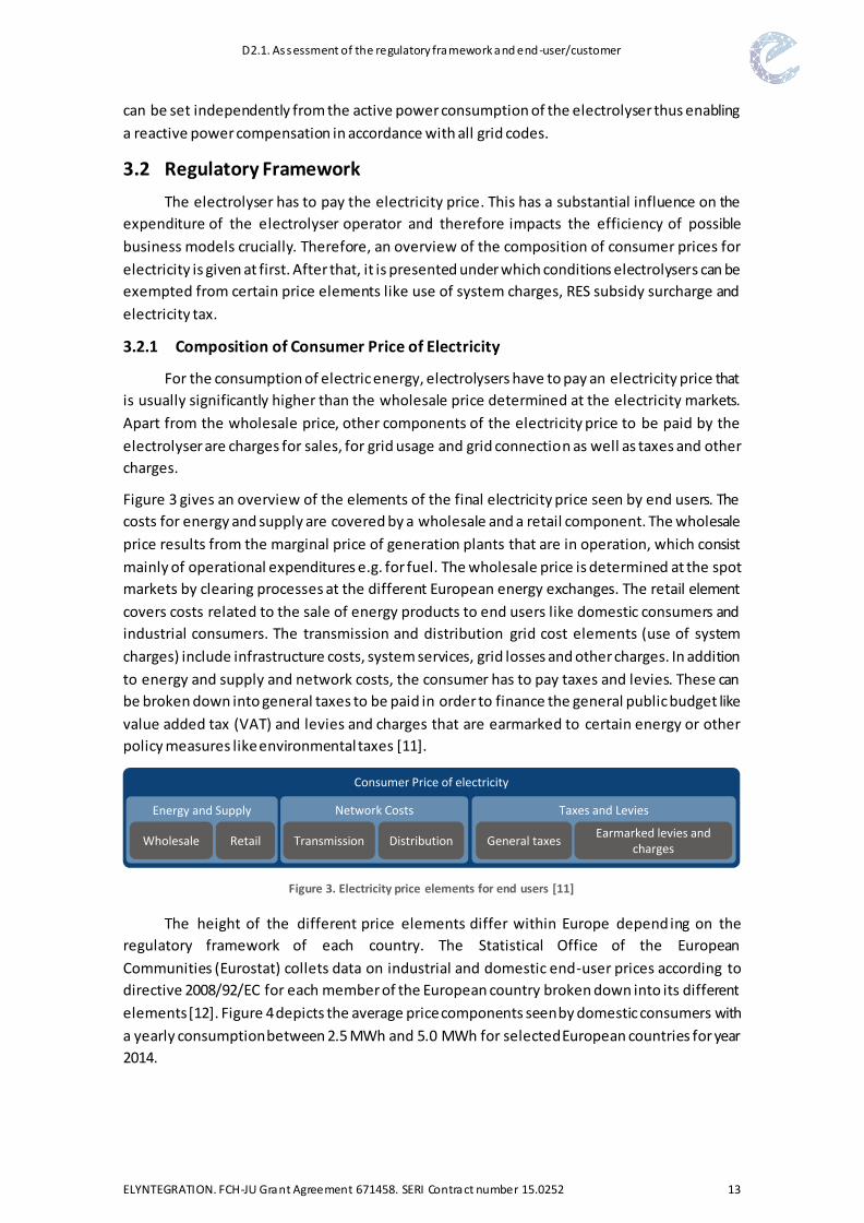
Figure 3 gives an overview of the elements of the final electricity price seen by end users. The
costs for energy and supply are covered by a wholesale and a retail component. The wholesale
price results from the marginal price of generation plants that are in operation, which consist
mainly of operational expenditures e.g. for fuel. The wholesale price is determined at the spot
markets by clearing processes at the different European energy exchanges. The retail element
covers costs related to the sale of energy products to end users like domestic consumers and
industrial consumers. The transmission and distribution grid cost elements (use of system
charges) include infrastructure costs, system services, grid losses and other charges. In addition
to energy and supply and network costs, the consumer has to pay taxes and levies. These can
be broken down into general taxes to be paid in order to finance the general public budget like
value added tax (VAT) and levies and charges that are earmarked to certain energy or other
policy measures like environmental taxes [11].
Figure 3. Electricity price elements for end users [11]
The height of the different price elements differ within Europe depending on the
regulatory framework of each country. The Statistical Office of the European
Communities (Eurostat) collets data on industrial and domestic end-user prices according to
directive 2008/92/EC for each member of the European country broken down into its different
elements [12]. Figure 4 depicts the average price components seen by domestic consumers with
a yearly consumption between 2.5 MWh and 5.0 MWh for selected European countries for year
2014.
Consumer Price of electricity
Energy and Supply Network Costs Taxes and Levies
Wholesale Retail Transmission Distribution General taxesEarmarked levies and
charges

D2.1. Assessment of the regulatory framework and end-user/customer
ELYNTEGRATION. FCH-JU Grant Agreement 671458. SERI Contract number 15.0252 14
Due to the increasing harmonization of European internal energy markets, the difference
between the wholesale prices is moderate. However, based on individual national regulatory
frameworks, the amount and height of additional price elements to be paid by end users differ
significantly for the examined countries. The resulting overall electricity price for domestic
consumers shows not only significant differences within Europe but is also considerably higher
than the wholesale price. Within Germany and Italy, the difference between end user price and
wholesale price is highest. Here, domestic consumers pay a price nine times higher than the
wholesale market price. In countries with a low spread between end user and wholesale price
like in Poland, the price for domestic consumers is still three times higher than the wholesale
price.
Figure 4: Average electricity prices and their break down into components for domestic consumers (2.5 MWh – 5.0 MWh) in 2014 by country [13] [14] [15] [16]
Figure 5 depicts the average price components seen by industrial consumers with a yearly
consumption between 20 MWh and 500 MWh for selected European countries for year 2014. A
comparison with electricity prices for domestic consumers (Figure 4) shows that industrial
consumers generally face lower end user prices than domestic consumers. Figure 6 depicts the
average price components for industrial consumers with a yearly consumption between 20 GWh
and 70 GWh. It can be seen that industrial consumers with this consumption face even lower
end user prices. This is mainly due to reduced network costs and the retail prices.
The strategic goal of ELYntegration project is the design of a multi megawatt electrolyser.
Assuming an electrolyser size of 10 MW and full load hours of at least 2,000 hours per year
results in a yearly consumption of at least 20 GWh. Consequently, for such an electrolyser design
end user price components depicted in Figure 6 are most likely to be relevant.
Energy and Supply
Network Costs
Taxes and Levies
Wholesale Price
0
100
200
300
Pri
ce in
€/M
Wh
Country

D2.1. Assessment of the regulatory framework and end-user/customer
ELYNTEGRATION. FCH-JU Grant Agreement 671458. SERI Contract number 15.0252 15
Figure 5: Average electricity prices and their break down into components for industrial consumers (20 MWh – 500 MWh) in 2014 by country [13] [14] [15] [16]
Figure 6: Average electricity prices and their break down into components for industrial consumers
(20 GWh – 70 GWh) in 2014 by country [13] [14] [15] [16]
Since the height of end user prices is highly relevant for the efficiency of potential business
models for an electrolyser, for a proper evaluation not only the wholesale price of each country
Energy and Supply
Network Costs
Taxes and Levies
Wholesale Price
0
100
200
300P
rice
in €
/MW
h
Country
Energy and Supply
Network Costs
Taxes and Levies
Wholesale Price
0
100
200
300
Pri
ce in
€/M
Wh
Country

D2.1. Assessment of the regulatory framework and end-user/customer
ELYNTEGRATION. FCH-JU Grant Agreement 671458. SERI Contract number 15.0252 16
has to be taken into account but also the regulatory framework differentiated by country. High
taxes and levies or use of system charges are expected to have a negative impact on the
economic efficiency. Within some countries, electrolysers are exempted from certain taxes or
charges. Therefore, it is necessary to clarify in which countries and to what extent a reduction
of the end user price is to be expected for electrolysers. The definition of electrolysers as an
industrial consumer instead of a domestic consumer may also reduce the end user price.
3.2.2 Use of System Charges
The use of system charges covers the costs for operating and maintaining a safe and
reliable transmission and distribution system. They are paid by the end users to the transmission
and distribution system operators who have to take appropriate measures within grid expansion
planning (e.g. new power lines) as well as operation planning (e.g. redispatch) to secure a safe
and reliable system. Within most European countries, these charges are independent of the
geographical distance between power injection and consumption. The height of the charges
depends on the grid area as well as the voltage level to which the end user is connected.
Figure 7 shows the use of system charges for end users with a registered power
measurement exemplarily for the German distribution grid operator Westnetz GmbH. According
to § 12 StromNZV, this applies for all end users with an annual consumption of electrical energy
of more than 100 MWh. The use of system charges are divided into a price for the maximum
power consumption of the end user and price for the annual consumed energy. The height of
power and energy price is dependent on the full load hours and the voltage level for gri d
connection. Independent of the full load hours, all end users face lower prices for both power
and energy with a higher voltage level.
Figure 7. Use of system charges for end users with registered power measurement [17]
Especially the increased share of renewable energy sources in the power system has a
mayor influence on the network costs. A suitable operation of electrolysers as a storage unit for
electrical energy can loosen the stress of the transmission and distribution grid induced by the
feed-in of renewable energy sources. Consequently, electrolysers can reduce the need for grid
expansion respectively operation planning measures and thus reduce the network costs.
0
10
20
30
40
0
20
40
60
80
MV grid HV/MVsubstation
HV grid MV grid HV/MVsubstation
HV grid
Pri
ce f
or
Ener
gyin
€/M
Wh
Pri
ce f
or
Po
we
r in
€/k
W
Voltage level
Price for Power Price for Energy
Full Load Hours < 2500 h/a Full Load Hours ≥ 2500 h/a

D2.1. Assessment of the regulatory framework and end-user/customer
ELYNTEGRATION. FCH-JU Grant Agreement 671458. SERI Contract number 15.0252 17
Therefore, within Germany, electrolysers are exempted from use of system charges under
specific circumstances. The conditions for an exemption are defined within the Energy Industry
Act (§ 118 EnWG). Electrolysers that are installed within the period between 04.08.2011 and
04.08.2026 are exempted from use of system charges for a period of 20 years. The legal position
on the question if the exemption from use of system charges also includes the exemption from
other charges that are defined as an additional charge on top of the use of system charges is still
unclear. This includes the apportionment for combined heat and power (§ 9 KWKG), the
apportionment for liability of offshore wind power plants (§ 17 EnWG), the concession fee and
the apportionment according to § 19 StromNEV.
Within other European countries, e.g. in Spain, there is no distinction between
electrolysers and regular consumers. An exemption from use of system charges is therefore
currently not possible.
3.2.3 RES Subsidy Surcharge
Within Germany, the RES subsidy surcharge is an apportionment for the promotion of the
exploitation of renewable energy sources to be paid through the end user price for electricity.
This surcharge is specified within the Renewable Energy Law (§ 61 EEG). As storage units for
electrical energy, electrolysers are exempted from the RES subsidy surcharge if the electrolyser
hydrogen or methane is used for storage purposes only and used temporally delayed for feed-
in into the electric grid (§ 60 EEG). Electrolysers are also exempted from the subsidy charge if
the electrolyser is located within the vicinity of RES power plants and the supply of electricity is
done without usage of the public transmission or distribution grid.
Within other European countries, subsidy surcharges also apply for all electric energy
storage systems. Therefore, electrolysers are currently not exempted from the RES subsidy
surcharge.
3.2.4 Electricity Tax
The electricity tax was originally introduced in Germany in order to increase the electricity
price for consumers aiming at a reduction of electric energy consumption. Exemptions for
electrolysers from this tax are regulated within the electricity tax law (StromStG). According to
§ 9 StromStG, storage units are exempted from the electricity tax if the electric energy
consumed by the storage unit is supplied by RES power plants or the consumption is connected
to RES power plants within close vicinity of the storage unit and the rated power of the storage
unit is less than 2 MW. The electricity tax is also not applied, if the unit is used solely for storage
purposes and the stored energy is fed into the electric grid temporally delayed. According to
§ 9 StromStG, electrolysers are additionally exempted from the electricity tax in case of
industrial consumers.
Within other European countries, in terms of electricity tax there is currently no special
treatment for energy storage systems and electrolysers are not exempted.
3.2.5 Interim Conclusion
For the determination and evaluation of potential business models, the electricity price
for the electrolyser is essential. It is therefore not sufficient to investigate the wholesale price
determined at the electricity markets since the end user prices can be up to nine times higher

D2.1. Assessment of the regulatory framework and end-user/customer
ELYNTEGRATION. FCH-JU Grant Agreement 671458. SERI Contract number 15.0252 18
due to payments for supply, use of system charges and taxes and levies. These price elements
are highly dependent on the national regulatory framework. Consequently, the end user prices
within European countries differ significantly. The efficiency of potential business models for
electrolysers is therefore not only dependent on the wholesale prices but also on the regulatory
framework in each country. For Germany, it is necessary to consider possi ble exemptions for
electrolysers from user of system charges, RES subsidy surcharge and the electricity tax. Within
other European countries, there are currently no exemptions for electrolysers available.
3.3 Grid services
In order to maintain a stable and rel iable system operation, transmission system
operators provide grid services which include frequency stability through control reserve and
grid congestion management such as redispatch. Furthermore, distribution system operators
account for a stable distribution grid operation, which as well relies on grid services.
Transmission system operators and distribution system operators represent possible customers
for electrolyser applications if the electrolyser can comply with requirements during operation.
Those applications may include different types of control reserve, substitution for redispatch
interventions and possibly services for stabilising distribution grids. In order to assess the
suitability of electrolysers for different services, regulatory and technical requirements will be
analysed in the following sections. Besides an overview of different possible commitments, an
analysis of the specific situation in Germany and further details about requirements in Spain and
other important European countries is conducted.
3.3.1 Control Reserve
Frequency deviations are balanced by control reserve, which means that suitable
technical units provide positive and negative reserve by raising or lowering their generation or
consumption when necessary. The following section gives an overview of the different types of
control reserve in Europe. The detailed conditions in national reserve markets decide whether
a participation is possible for electrolysers. Thus, the current situation with details about
electrolyser and consumer participation and details about activation requirements are analysed
as well as an outlook to possible future market developments is given. A more detailed analysis
of technical requirements for providing control reserve is provided in sections 3.3.2 and 3.3.3.
Current Situation
The European control areas are currently structured by national policies, which differ in
their market design. Overall, the reserve market can be divided into four common types of
control reserve, which correspond in their functions but show differences in their precise
arrangement for example in activation time. Figure 8 shows the succession of the different types
of control reserves, which are consecutively activated after a disturbance.

D2.1. Assessment of the regulatory framework and end-user/customer
ELYNTEGRATION. FCH-JU Grant Agreement 671458. SERI Contract number 15.0252 19
Figure 8. Consecutive activation of different types of control reserve
The Frequency Containment Reserve (FCR) is used for balancing within seconds. In
Germany for example, the required activation time is below 30 s [18]. This means that Frequency
Containment Reserve requires a very fast reacting reserve, usually a spinning reserve, which
then is not suitable for provision by electrolysers. Subsequently, the automatic Frequency
Restoration Reserve (aFRR) follows, which is used for automatic short term balancing of
frequency deviations, then followed by the manual Frequency Restoration Reserve (mFRR),
which is manually activated if deviations are continuing. Furthermore, some countries contract
the Replacement Reserve (RR), which follows in order to replace capacities if an outage is
continuing further on. In Germany, the automatic Frequency Restoration Reserve has to be fully
activated within 5 minutes, and manual Frequency Restoration Reserve has an activation time
of 15 minutes [18]. Both might be suitable business models, so prequalification requirements
will be analysed later on. Activation times for other European countries are summarised in Table
2. The Spanish market for example is similarly arranged with three types of control reserve with
a lot of identical properties. While the Frequency Containment Reserve and the manual
Frequency Restoration Reserve require the same activation time as in Germany, the automatic
Frequency Restoration Reserve has to be activated within 30 s [19, 20]. This ramping
requirement might pose an obstacle for the technical suitability of electrolysers. From a
technical view, the manual Frequency Restoration Reserve might be provided by electrolysers
in Spain.
Besides technical requirements, the regulatory side plays an important role for
electrolyser market participation. For the commitment of electrolysers in reserve markets, it is
crucial that the market is opened to electricity customers. Consumer participation is considered
in terms of demand response policies. The objective of promoting demand response is
mentioned within the European Network Codes [21] and the European Commission’s Energy
Union Communication [22], but so far some European countries fail to acknowledge and accept
the technological field in control reserve markets.
Table 2 provides a review of European countries in terms of acceptance of demand
response in reserve markets, the acceptance of aggregated loads and details about activation
times for countries which accept electrolysers for reserve markets.
Load
/ F
req
uen
cy FCR
FRR
automaticmanual
RR
TimeActivation time specified by national policies

D2.1. Assessment of the regulatory framework and end-user/customer
ELYNTEGRATION. FCH-JU Grant Agreement 671458. SERI Contract number 15.0252 20
Country Notation Participation Participation by agg. loads
Activation time
Tenders
Austria, Germany,
Switzerland
FCR 30 s weekly aFRR 5 min weekly
mFRR 15 min 4 hours RR - - - -
Belgium
FCR * * 15 - 30 s
annual aFRR -
mFRR * * 3 - 15 min
RR -
Denmark
FCR 30 - 150 s N/A
aFRR 15 min N/A mFRR N/A N/A
RR N/A N/A
Finland
FCR inst. - 3 min annual
aFRR 2 min annual
mFRR 15 min N/A RR 15 min N/A
France
FCR < 30 s
flexible aFRR < 15 min
mFRR 13 min RR 30 min - 2 hrs
Great Britain
FCR 2 s flexible but long-term (e.g. daily weekday participation)
aFRR 2 min mFRR - - -
RR 2- 4 hours
Ireland, Italy,
Poland, Spain
FCR -
- aFRR - mFRR -
RR -
Netherlands
FCR - aFRR N/A annual
mFRR N/A voluntary bids RR - - - -
Norway
FCR 5 - 30 s hourly, weekly aFRR 2 min weekly
mFRR 15 min weekly, seasonal
RR - -
Slovenia
FCR N/A
annual aFRR N/A mFRR 15 min
RR - - -
Sweden
FCR 5 s - 3 min daily
aFRR 2 min weekly
mFRR 15 min hourly RR 15 min yearly
* partially accepted Demand Response accepted Demand response not accepted - Reserve does not apply N/A Information not available
Table 2. Demand response and activation time for control reserve in European countries [18, 19, 20, 23]

D2.1. Assessment of the regulatory framework and end-user/customer
ELYNTEGRATION. FCH-JU Grant Agreement 671458. SERI Contract number 15.0252 21
As of now, countries that accept consumers and thus electrolysers as participants are
Austria, Denmark, Finland, France, Germany, Great Britain, Switzerland and Sweden. Countries
that accept demand response for selected types of control reserve are Belgium, the
Netherlands, Norway and Slovenia. Not accepted as control market bidders are electrolysers in
Ireland, Italy, Poland and Spain [23]. The acceptance of aggregated loads indicates whether small
units can participate in markets by pooling arrangements if they fail to reach required minimum
lots on their own. For example, in Germany the minimum lot is +/- 1 MW for Frequency Control
Reserve and 5 MW for Frequency Restoration Reserve [18]. Further influence on market
participation of electrolysers has the length of tenders, as short tenders allow flexibility in
business models with electrolysers dispatch reacting to electricity prices. They will be analysed
in the following sections.
Future Development
The development of control reserve specifications in the next years is relevant for the
identification of end-user requirements, as electrolysers should meet required specifications
during their entire operating period of several years. To some extent, future developments can
be derived from recent trends.
In Europe, harmonisation efforts by European transmission system operators are made,
which aim to share balancing resources between countries and to develop cross border
balancing markets [24, 25]. In consideration of these efforts, homogenous types of control
reserve might develop in the future. So far, a definite time frame for the development and
detailed design of control reserve specifications cannot be distinctly defined. Thus, national
developments may be used to indicate recent trends.
In Germany, time frames, tenders and minimum lots for different control reserve types
have undergone considerable changes. Within the last few years, the reduction of minimum lots,
the acceptance of pooling of units for reaching minimum lots with small units, as well as the
acceptance of electricity customers as bidders are recent developments that opened the
markets to new participants. Furthermore, the time frame for which procurement is conducted
has become shorter. The two types of Frequency Restoration Reserve used to be procured every
half year until the release of the Transmission Code 2007, currently it is a daily procedure for
automatic Frequency Restoration Reserve and a weekly procedure for manual Frequency
Restoration Reserve [18]. The same tendency can be observed for shortened tenders [26]. Those
tendencies are likely to proceed in the future, leading to even shorter time frames and tenders
and opening markets to multiple participants. In Spain on the other hand, the acceptance of
electricity customers such as electrolysers as bidders on control reserve markets is currently the
main obstacle for establishing new business models in that field and the future development is
not yet foreseeable. Currently the national power system is over capacitated, with high shares
of manageable power plants based on natural gas operating less than 1000 hours per year, and
with an inadequate regulatory framework to promote renewable energies. With this context the
necessity to increase the power reserve is limited and pumped heat electrical storage seems to
be a good solution in the short term. A change in the politics with renewable energies in Spain
can change the situation in the mid-term.
To summarize, the developments in Europe are currently not on the same level and
national distinctions are still a decisive factor. With increasing harmonisation, short tenders and

D2.1. Assessment of the regulatory framework and end-user/customer
ELYNTEGRATION. FCH-JU Grant Agreement 671458. SERI Contract number 15.0252 22
open markets for electricity customers, a market participation of electrolysers would become
easier. Still, countries should be carefully chosen for electrolyser placement because a few
markets do not promise the development of accepting electrolysers for reserve control, e.g.
Spain. However, a possible market harmonisation with a decrease of differences between
European countries as well as short tenders and open and connected markets would also imply
a reduction of demand and balancing costs and an enhancement of security of supply. For
electrolysers, this would result in a higher competition, lower prices on reserve markets and
lower contribution margins.
3.3.2 Automatic Frequency Restoration Reserve
As automatic Frequency Restoration Reserve may identify as a possible future business
model for electrolysers, the technical requirements for market participation are further
analysed.
Generally, the prequalification procedure ensures the technical suitability of technical
units and the security of supply. Only successfully prequalified units are approved to participate
in the control power market. In order to examine the prequalification process in further detail,
an exemplary analysis of the German prequalification procedure is conducted in the following.
It is to be expected that the procedure is generally related in other European countries, but
differences occur in detailed specifications. For example, an important technical feature which
differs depending on the country is the ramping ability. For European countries which accept
demand response, it can be derived for different types of control reserve from activation times
as shown in Table 2.
The main prerequisites for participation in any German control reserve market can be
divided into technical and organisational requirements and requirements for instrumentation
and control. The most important technical requirements are summarized in Table 3.
General ramping requirement at least 2 % of nominal power per minute
Technical reliability > 95 %
Activation and control automatic activation online by TSO or pooling operator
Tender one week
Operating mode Regulation not explicit, possibly continuous synchronization for entire tender
Activation time < 5 min
Table 3. Technical requirements for automatic Frequency Restoration Reserve in Germany [18]
It is generally required that the units participating as automatic Frequency Restoration
Reserve have a ramping ability of at least 2 % of nominal power and that units can be
automatically activated online by the transmission system operator or the pooling provider. A
technical reliability of at least 95 % is required, which has to be verified for the time period of
the tender [18].
Concerning the operating mode, the regulatory instructions are not explicit for
electrolysers, as regulation distinguishes between thermal and hydraulic units and electrolysers
can’t be clearly assigned to one of the two categories. Generally, technical units have to remain

D2.1. Assessment of the regulatory framework and end-user/customer
ELYNTEGRATION. FCH-JU Grant Agreement 671458. SERI Contract number 15.0252 23
synchronized to the grid for the entire time of the tender, which is one week, in order to ensure
provision of services. For hydraulic units, an exemption is possible if the ramping ability is at
least 2 % of the nominal power per second and the power ramp time is below 5 minutes [18]. If
a continuous operation is required, this amounts to an exclusion of electrolysers as market
participants, because with current prices, a week long continuous electricity procurement
without price consideration would lead to high deficits.
The activation time of 5 minutes refers to the time in which the full prequalified power
needs to be available in both power directions. For evidence, an operation schedule as
exemplary displayed in Figure 9 has to be completed.
Figure 9. Ramping protocol for automatic Frequency Restoration Reserve in Germany [18]
The operation protocol proves that the unit is able to ramp up to maximal prequalified
power within 5 minutes, maintain power for a given amount of time and ramp down to initial
power within 5 minutes. A possible delay time of the unit, displayed in Figure 10, is included
within the ramping time. This test has to be successfully completed twice within one hour.
During the test, a brief overshoot of at most 5 % of the target value but at most 5 MW is
permitted. The performance has to be reproducible. [18]
Figure 10. Accepted delay time for automatic Restoration Reserve in Germany [18]
Technical requirements furthermore include grid connection specifications, with state
that no technical units that are affected by grid restrictions can be prequalified and that if the
unit is not connected to the transmission grid, the respective distribution system operator has
to sign an agreement for the provision of reserve control. [18]
0 15 30 45 60
po
we
r co
nsu
mp
tio
n
minutesactual value target value
0 5 10 15
po
we
r co
nsu
mp
tio
n
minutes
idealized ramping value actual value target value

D2.1. Assessment of the regulatory framework and end-user/customer
ELYNTEGRATION. FCH-JU Grant Agreement 671458. SERI Contract number 15.0252 24
Concerning instrumentation and control, requirements for automatic Frequency
Restoration Reserve are comparatively high, because the automatic activation and online
observation is conducted. This includes a redundant data connection, point-to-point-
connection, a control cycle time of at most 4 seconds, a telecontrol protocol and a spontaneous
transmission of reports. The transmitted technical data contains the actual generation and
operating point of each unit, desired value and actual value of control power at the time, status
information (on/off) and upper and lower limits of the control power range. [18]
On an organisational level, if pooling is conducted, the pooling provider verifies the
qualification of the pool for providing the respective reserve in addition to the prequalification
tests for the technical suitability for individual units. Furthermore, confirmations e.g. of
compliance with directives for reserve control by the supplier of a balancing group and by the
operator have to be supplied. [18]
In summary, the technical suitability of electrolysers for providing automatic Frequency
Restoration Reserve has to be proven during a prequalification procedure. The most important
technical requirement concerns ramping abilities. Control power has to be fully available within
2 to 5 minutes, sometimes 15 minutes depending on the considered country. Furthermore,
automatic control by reserve operators is mandatory, which leads to extensive requirements for
instrumentation and control.
3.3.3 Manual Frequency Restoration Reserve
Manual Frequency Restoration Reserve requires lower ramping abilities, typically around
15 minutes. The prequalification procedure generally follows the same process as for automatic
Frequency Restoration Reserve. For that reason, only main differences in requirements are
specified in the following with focus being on the German regulations in order to give a specific
example. Requirements concerning organisational requirements, pooling and grid connection
do not differ from automatic Frequency Restoration Reserve.
Table 4 lists the technical requirement for manual Frequency Restoration Reserve. As the
notation suggests, manual Frequency Restoration Reserve prequalification only demands
manual activation done via telephone so online controllability is not necessary. For
instrumentation and control, this implies lower requirements so that no detailed connection
specification but only the transmission of information such as actual generation, provided
control power, desired value of control power and actual value of control power and status
information is listed [18].
General ramping requirement no general requirement
Activation and control manual activation by telephone
Tender 4 hours
Operating mode no requirement of continuous synchronization
Activation time < 15 min
Technical reliability > 100 %
Table 4. Technical requirements for manual Frequency Restoration Reserve in Germany [18]

D2.1. Assessment of the regulatory framework and end-user/customer
ELYNTEGRATION. FCH-JU Grant Agreement 671458. SERI Contract number 15.0252 25
Tenders for manual Frequency Restoration Reserve are 4 hours, so a lot shorter than
tenders for automatic Frequency Restoration Reserve [18]. Short tenders enable a flexible
market participation for bidders so their commitment may react for example to spot market
prices. Also, as the activation time is longer on this market, units are not required to react as
quickly as for automatic Frequency Restoration Reserve. This implies that there is no general
requirement for general ramping speed or for continuous synchronization for the time of the
tender. The activation time is set at < 15 minutes for full availability of the reserve power output.
For evidence, an operational protocol as in Figure 11 has to be submitted that proves that
ramping was successfully completed twice within two hours. The technical reliability of mFRR
units is required to be 100 %, it can be ensured by pooling bids [18].
Figure 11. Operational protocol for automatic Frequency Restoration Reserve in Germany [18]
To conclude, a successful prequalification for manual Frequency Restoration Reserve
requires lower technical abilities from electrolysers, because activation times are longer with
around 15 minutes and thus lower ramping abilities are necessary. Also, a manual activation of
the electrolyser is intended so requirements for instrumentation and control are modest.
3.3.4 Distribution Grid Services
Distribution grid services may be a possible electrolyser application. Electrolysers can be
used for relieving distribution grid congestions which happen with an increased frequency due
to higher infeed by renewables energy systems. Depending on the future development, even an
extensive application of storage units such as electrolysers in distribution grids might be possible
if this proves to be an economically efficient option. However, the application of electrolysers in
distribution grids is a fairly new development and it isn’t established within policies or
regulations yet. Thus, definite technical requirements by distribution system operators couldn’t
be identified, as well as there is no regulated compensation established.
Generally, a flexible operation is essential for effective smoothing of feed-in peaks that
cause congestions. Thus, a high tolerance for a flexible mode of operation and good ramping
characteristics are necessary for successfully providing distribution grid services.
3.3.5 Interim Conclusion
Grid services present different options as possible business models for electroly sers.
Opportunities may be in transmission grid services and distribution grid services. Both are
regulated on national levels, so individual regulations in European countries have to be taken
0 15 30 45 60 75 90 105 120 135
po
we
r co
nsu
mp
tio
n
minutesactual value target value

D2.1. Assessment of the regulatory framework and end-user/customer
ELYNTEGRATION. FCH-JU Grant Agreement 671458. SERI Contract number 15.0252 26
into consideration. For the provision of control reserve as a transmission grid service, technical
requirements such as ramping abilities have to be considered for assessing the technical
suitability of electrolysers. From that aspect, automatic and manual Frequency Restoration
Reserve present promising markets. In order to participate in those markets, countries have to
accept electrolysers as consumers as market participants. This is not yet given in all European
countries. Another transmission grid service option for electrolysers is redispatch. There, no
explicitly defined technical requirements exist, but a flexible operation ability is necessary.
Distribution grid services aren’t commonly established yet, so no strictly defined requirements
exist, but again a flexible operation will be obligatory in order to complete the task of congestion
reliefs.

D2.1. Assessment of the regulatory framework and end-user/customer
ELYNTEGRATION. FCH-JU Grant Agreement 671458. SERI Contract number 15.0252 27
4 CONCLUSIONS
The research and innovation project “Grid Integrated Multi Megawatt High Pressure
Alkaline Electrolysers for Energy Applications” is focused on the design and engineering of a
robust, flexible, efficient and cost-competitive electrolyser. To meet technical and economical
requirements, a commercial deployment of an electrolyser has to take into account a lot of
steps. This deliverable focused the clarification of the end-user’s requirements.
From the simple perspective from an electricity grid, an electrolyser is a customer who
uses the grid to consume electricity and has to meet a technical framework from the grid
operator. Furthermore the regulatory framework affects the end-user requirements. Especially,
in case of new business models.
Therefore, this deliverable worked on three areas:
Grid connection
Regulatory framework
Grid services
For the grid connection, technical requirements concerning the restriction of grid
disturbances are not expected to be critical. Because of its load behaviour rapid voltage changes
and due to its three-phase grid connection via voltage source converter voltage phase
unbalances and commutation notches are no critical restrictions for an electrolyser. For all other
technical requirements being relevant due to the switching characteristics of the power
electronic interface appropriate countermeasures exist and are state of the art. Due to the
voltage source converter characteristic of the power electronics interface, the reactive power
can be set independently from the active power consumption of the electrolyser thus enabling
a reactive power compensation in accordance with all grid codes.
The electricity end user price for the electrolyser is essential. The individual price elements
are highly dependent on the national regulatory framework. Consequently, the end user prices
within European countries differ significantly. The efficiency of potential business models for
electrolysers is therefore not only dependent on the wholesale prices but also on the regulatory
framework in each country. For example, in Germany it is necessary to consider possible
exemptions for electrolysers from use of system charges, RES subsidy surcharge and the
electricity tax.
Additional, business models may be in transmission grid services and distribution grid
services. Both are regulated on national levels, so individual regulations in European countries
have to be taken into consideration. For the provision control reserve as a transmiss ion grid
service, technical requirements such as ramping abilities have to be considered for assessing the
technical suitability of electrolysers. From that aspect, automatic and manual Frequency
Restoration Reserve presents promising markets. In order to participate in those markets,
countries have to accept electrolysers as consumers as market participants. Another
transmission grid service option for electrolysers is redispatch or distribution grid services. There
are no strictly defined requirements, yet.

D2.1. Assessment of the regulatory framework and end-user/customer
ELYNTEGRATION. FCH-JU Grant Agreement 671458. SERI Contract number 15.0252 28
5 REFERENCES
[1] Westnetz GmbH, “Technische Anschlussbedingungen Mittelspannung,” [Online].
Available: http://www.westnetz.de/web/cms/mediablob/de/1756722/data/0/9/
Mittelspannung.pdf. [Accessed 20 Januar 2016].
[2] Westnetz GmbH, “Maximale Anschlusskapazitäten,” [Online]. Available:
http://www.westnetz.de/web/cms/de/1903732/westnetz/netz-
strom/netzanschluss/maximale-anschlusskapazitaeten-orientierungswerte/. [Accessed
06 Januar 2016].
[3] International Electrotechnical Commission, Electromagnetic compatibility (EMC) - Part 3-
3: Limits - Limitation of voltage changes, voltage fluctuations and flicker in public low-
voltage supply systems, for equipment with rated current ≤16 A per phase and not subject
to conditional connection, 2013.
[4] International Electrotechnical Commission, “IEC/TR 61000-3-6, Electromagnetic
compatibility (EMC) - Part 3-6: Limits - Assessment of emission limits for the connection of
distorting installations to MV, HV and EHV power systems,” 2008.
[5] International Electrotechnical Commission, “IEC/TR 61000-3-7, Electromagnetic
compatibility (EMC) - Part 3-7: Limits - Assessment of emission limits for the connection of
fluctuating installations to MV, HV and EHV power systems,” 2008.
[6] German Association of Energy and Water Industries, “Technical Conditions for Connection
to the medium-voltage network,” Berlin, 2008.
[7] REE, “Guía descriptiva del procedimiento de conexión a la red,” 2015. [Online]. Available:
http://www.ree.es/sites/default/files/01_ACTIVIDADES/Documentos/AccesoRed/
Guia_procedimiento_conexionalared_V5_dic15.pdf.
[8] Real Decreto 1955/2000, de 1 de diciembre, por el que se regulan las, “BOE,” 4 December
2015. [Online]. Available: https://www.boe.es/buscar/pdf/2000/BOE-A-2000-24019-
consolidado.pdf.
[9] N. Mohan, T. M. Undeland and W. P. Robbins, Power Electronics - Converters, Applications
and Design, Hoboken, US: John Wiley & Sons, 2003.
[10] Iberdrola, “Regulated prices for electricty and gas 2015,” 2015. [Online]. Available:
https://www.iberdrola.es/02sica/gc/prod/es_ES/hogares/docs/Triptico_tarifas2015.pdf.
[11] E. Commission, “Energy prices and costs report,” Brussels, 2014.
D2.1. Assessment of the regulatory framework and end-user/customer
ELYNTEGRATION. FCH-JU Grant Agreement 671458. SERI Contract number 15.0252 29
[12] European Parliament, “Directive 2008/92/EC of the European Parliament and of the
Council of 22 October 2008 concerning a Community procedure to improve the
transparency of gas and electricity prices charged to industrial end-users,” Strasbourg,
2008.
[13] Statistical Office of the European Union, “Eurostat,” [Online]. Available:
http://ec.europa.eu/eurostat/data/database. [Accessed 14 01 2016].
[14] E. Commission, “Quarterly Report on European Electricity Markets - Market Observatory
for Energy DG Energy, Volume 6 (third and forth quarter of 2013) and Volume 7 (first and
second quarter of 2014),” Brussel, Belgium, 2014.
[15] E. Commission, “Quarterly Report on European Electricity Markets - Market Observatory
for Energy DG Energy, Volume 7 (fourth quarter of 2014),” Brussel, Belgium, 2014.
[16] E. Commission, “Quarterly Report on European Electricity Markets - Market Observatory
for Energy DG Energy, Volume 7 (third quarter of 2014),” Brussel, Belgium, 2014.
[17] Westnetz GmbH, “Entgelte für Netznutzung,” [Online]. Available:
http://www.westnetz.de/web/cms/mediablob/de/2290308/data/0/9/
Netznutzungspreise-gueltig-vom-01.01.15-bis-31.12.15-.pdf. [Accessed 14 01 2016].
[18] H. Berndt, M. Herman, D. Kreye, R. Reinisch, U. Scherer and J. Vanzatta, “TransmissionCode
2007 - Netz- und Systemregeln der deutschen Übertragungsnetzbetreiber,” Verband der
Netzbetreiber VDN e.V. beim VDEW, Berlin, 2007.
[19] BOE, “RESOLUCIÓN de 30 de julio de 1998, de la Secretaría de Estado de Energía y recursos
Minerlaes, por la que se aprueba un comjunto de procedimientos de carácter técnico e
instrumental necesarios para realizar la adecuada gestión técnica del sistema eléctric,”
[Online]. Available: http://www.ree.es/sites/default/files/01_ACTIVIDADES/Documentos/
ProcedimientosOperacion/PO_resol_ 30jul1998_b.pdf.
[20] BOE, “P.O. 7.2 Regulación secundaria & P.O. 7.3 Regulación terciaria,” 2015. [Online].
Available: http://www.ree.es/sites/default/files/01_ACTIVIDADES/Documentos/
ProcedimientosOperacion/RES_VAR_20151218_Participacion_en_servicios_de_
ajuste_y_aprobacion_POs.pdf.
[21] European Network of Transmission System Operators for Electricity ENTSO-E, “ENTSO-E
Network Code on Electricity Balancing,” European Network of Transmission System
Operators for Electricity ENTSO-E, Brussels, 2014.
[22] European Commission, “Communication from the Commission to the European
Parliament, the Council, the European Economic and Social Committee, the Committee of
the Regions and the European Investment Bank,” European Commission, Brussels, 2015.

D2.1. Assessment of the regulatory framework and end-user/customer
ELYNTEGRATION. FCH-JU Grant Agreement 671458. SERI Contract number 15.0252 30
[23] Smart Energy Demand Coalition (SECD), Mapping Demand Response in Europe Today
2015, Brussels: Smart Energy Demand Coalition, 2015.
[24] 50Hertz Transmission GmbH; Amprion GmbH; Elia System operator NV; TenneT TSo B.V.;
TenneT TSO GmbH; TransnetBW GmbH, “Potential Cross-Border Balancing Cooperation
Between the Belgian, Dutch and German Electricity Transmission System Operators,”
2014.
[25] European Network of Transmission System Operators for Electricity (ENTSO-E), “Cross
Border Electricity Balancing Pi lot Projects,” 25 01 2015. [Online]. Available:
https://www.entsoe.eu/major-projects/network-code-implementation/cross-border-
electricity-balancing-pilot-projects/Pages/default.aspx. [Accessed 25 01 2015].
[26] 50Hertz Transmission GmbH; Amprion GmbH; TenneT TSO GmbH; TransnetBW GmbH,
“regelleistung.net,” 25 01 2015. [Online]. Available:
https://www.regelleistung.net/ext/static/market-information. [Accessed 2015 01 2015].
[27] Bundesnetzagentur, “Quartalsbericht zu Netz- und Systemsicherheitsmaßnahmen,”
Bundesnetzagentur für Elektrizität, Gas, Telekommunikation, Post und Eisenbahn, Bonn,
2015.
[28] H.-P. Beck, “Studie Eigung von Speichertechnologien zum Erhalt der Systemsicherheit,”
Energie-Forschungszentrum Niedersachsen efzn, Goslar, 2013.