
FR8695_IndProj
12
Manufacturing Process Mechanics Individual Project (P2R2) NAME: SIDDHESH OZARKAR [email protected] DESIGNATION OF MODEL: P2R2 Model Number 2 with Radius of 0.015mm and 2 nd order elements (CPE8) used
-
Upload
siddhesh-ozarkar -
Category
Documents
-
view
12 -
download
2
Transcript of FR8695_IndProj
Manufacturing Process Mechanics
Individual Project (P2R2)
NAME: SIDDHESH OZARKAR
DESIGNATION OF MODEL: P2R2
Model Number 2 with Radius of 0.015mm and 2nd
order elements (CPE8) used

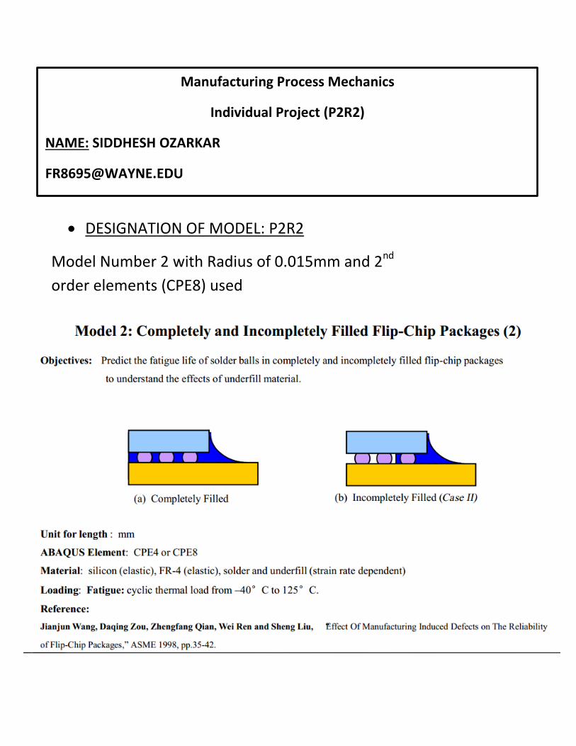
Abstract: The main objective of the paper is to compare the fatigue life of solder balls in
completely filled & incompletely filled flip-chip packages & to understand the effect of
the Under-fill. The fatigue life of both the models is calculated by using Coffin-Manson
equation. The results from the analysis show that,
A fully filled model has much higher fatigue cycle sustaining capacity.
The Incompletely filled model shows possibility of earlier failure.
Flip-Chip Package
The term ‘Flip-chip’ is defined as an electronic component or semiconductor device that can be mounted directly on a substrate, board, or carrier in a face-down manner.
Components In a flip-Chip Package
Flip-Chip Package
Chip Substrate Solder
Balls Underfill

Dimensions and Geometry of Model
Completely Filled Model
Solid Works Model
Chip
Substrate
Solder Balls
Underfill

Incompletely Filled
Model
Solid Works Model
Chip
Under-fill Solder-Balls
Substrate
Radius Given as per
requirement.

Pre-Processing
1) The geometry of both the models completely filled and Incompletely Filled flip-chip
packages is created as per the given dimensions in Solidworks.
2) Only surface geometry were created in Solidworks, the files were exported (.IGES) to Hypermesh
3) Meshing was performed on these models in Hypermesh.
4) Surfaces representing the various components were Independently Meshed so as to achieve finer mesh where required.
5) Finer mesh was created where potential high stress concentration was suspected like the solder balls.
6) Edges were set to equivalence after meshing.
7) Properties of the mesh
Element type – CPE8
Smallest element size- 0.01mm
8) A solver deck containing the material properties for the various components of the package was imported in the Hypermesh file directory.
This solver deck was assigned to the model so that respective elements have respective properties.
9) Boundary conditions were applied as follows - Constraint the left vertical side with DOF-1, bottom horizontal side with DOF-2, and intersection of both with DOF-1,2 .
10) All nodes were defined in one Entity set for the ease of utility. This entity set also contains the initial temperature condition of the model.
11) Create 4 load collectors were created as follows- Constraint
Initial Temp(20C)
Temperature 233 K (–40°C)
Temperature 398 K (125°C)
12) Create Output block and 3 Load step. Step 1- Initial increment= 10 over a time period of 600 sec at temperature of 233 K Step 2- Increment= 10 over a time period of 900 sec at temperature of 398 K Step 3- Increment= 10 over a time period of 600 sec at temperature of 233 K
13) The file was then exported to Abaqus for Further Analysis.

Completely Filled Model
Fine meshing in Critical
Areas.
Coarse Mesh
Fine Mesh
Coarse Mesh
Fine Mesh
Fine Mesh
Fine Mesh helps capturing
the curves and fillet radius
more precisely.

Incompletely Filled Model
Analysis
1) The input file generated from Hypermesh (.inp) was fed to the Abaqus solver.
2) The Abaqus solver after performing a fatigue analysis on the file gives the following results.
3) The output request consists of
Stress (S)
Strain (PE)
Displacement (U)
Nodal Temperature (NT)
Completely Filled Model Incompletely Filled Model

Fully Filled Model:
Calculation of fatigue life
Step 1:
Max Strain = 1.318e-02
Min Strain = 6.063e-03
Step 2:
Max Strain = 5.938e-02
Min Strain = 7.298e-03
Step 3:
Max Strain = 1.912e-01
Min Strain = 9.377e-03

Step 1:
Max Strain = 1.099e-02
Min Strain = 8.443e-03
Step 2:
Max Strain = 1.306e-02
Min Strain = 8.99e-03
Step 3:
Max Strain = 1.355e-02
Min Strain = 9.063e-03

Fatigue Life of Solder Balls:
According to the Coffin-Manson’s equation,
(Nf)β ΔγP = CP
Where, β = Fatigue ductility exponent (β= 0.51) Nf = Fatigue life ΔγP = Applied plastic/inelastic strain range CP = Fatigue ductility coefficient. (CP= 1.14)
Considering the rightmost solder ball for analysis:
Model Step Number Max. Strain Min. Strain
Fully Filled 1 1.318e-02
6.063e-03
- 2 5.938e-02
7.298e-03
- 3 1.912e-01
9.377e-03
Incompletely Filled 1 1.099e-02 8.443e-03
- 2 1.306e-02
8.991e-03
- 3 1.355e-02 9.063e-03
Solder Ball Fully Filled Step 1 Solder Ball Fully Filled Step 2
A A B
A
B
A
D
C
D
C
C

MODEL A B C D
Fully FILLED 42850 55206 73410 34361
Incompletely FILLED 33525 67705.67 67710 20005.11
Solder Ball Incompletely Filled Step 1 Solder Ball Incompletely Filled Step 2
A A B
A
B
A
C D
C
D
C
C
Displacement for Fully Filled Model
Displacement for Incompletely Filled
Model

CONCLUSION:
Fatigue life of completely filled model is higher than that of the
incompletely filled model.
As compared to models with no radius present at the corners of the
solder balls the ones with a radius present show higher fatigue
sustaining capacity.
Due to the presence of radius the strain is more distributed and thus
results in extended life of flip chip package.


