FDOT Plans Production Tools · FDOT Plans Production Tools FDOT State Kit for AutoCAD Civil 3D Mike...
36
FDOT Plans Production Tools FDOT State Kit for AutoCAD Civil 3D FDOT Plans Production Tools FDOT State Kit for AutoCAD Civil 3D Mike Racca CADD APPLICATIONS SUPPORT Florida Department of Transportation (ECSO) Email: [email protected] Phone: 850-245-1631
Transcript of FDOT Plans Production Tools · FDOT Plans Production Tools FDOT State Kit for AutoCAD Civil 3D Mike...

FDOT Plans Production ToolsFDOT State Kit for AutoCAD Civil 3D
FDOT Plans Production ToolsFDOT State Kit for AutoCAD Civil 3D
Mike Racca
CADD APPLICATIONS SUPPORT
Florida Department of Transportation (ECSO)
Email: [email protected]
Phone: 850-245-1631

FDOT Plans Production ToolsGENERALCivil 3D Plan Production Tools course helps you automate the creation of Sheets, Plan, Plan/Profile and Cross Section sheets.
The workflows created for use with Florida Department of Transportation (FDOT) plans are dependent on the following: Create a Civil 3D FDOT Project. - Information from the creation of the project is carried into the sheets and ultimately into the
Sheet Set Organizer (SSO) for organizing projects and preparing for electronic delivery. Creating a Sheet Set (dst) file - Displays and organizes named collections of drawings. Create a Key Sheet – Add Key Sheet to Sheet Set file. Data Shortcuts – Used only for the creation of data references such as Alignments, Surfaces, Pipe networks, and View Frames… Create View Frames wizard (Clip Borders for Plan and Plan/Profile View Sheets) Create Sheets wizard (Use to create Plan or Plan/Profile sheets and add to existing Sheet Set file) Create Section Sheets wizard (Use to create Cross Section Sheets and add to an existing Sheet Set file)
Create View frames are used to represent rectangular areas along the alignment that will be displayed on plan/profile or plan-only sheets. Before you create view frames, an alignment must already exist in your drawing. Depending on the type of sheets you want to produce (plan and profile or profile only), you may also need to have a profile already created. If you are creating a plan only view frame (or sheet set), then you do not need to have a profile in the drawing. *Command will not execute with out an alignment.
Create Sheets wizard to quickly create sheets for construction documents (plans) from View Frames. *Command will not execute with out an alignment.
Create Section Sheets command to create layouts for plotting section views and Sheets. As a prerequisite to using the Create Section Sheets command, you must use the “Sample Lines” and “Create Multiple Views” command to generate section views before you can Create Section Sheets. *Requires and Alignment, Sample Line Group Name and Section View Group.
2
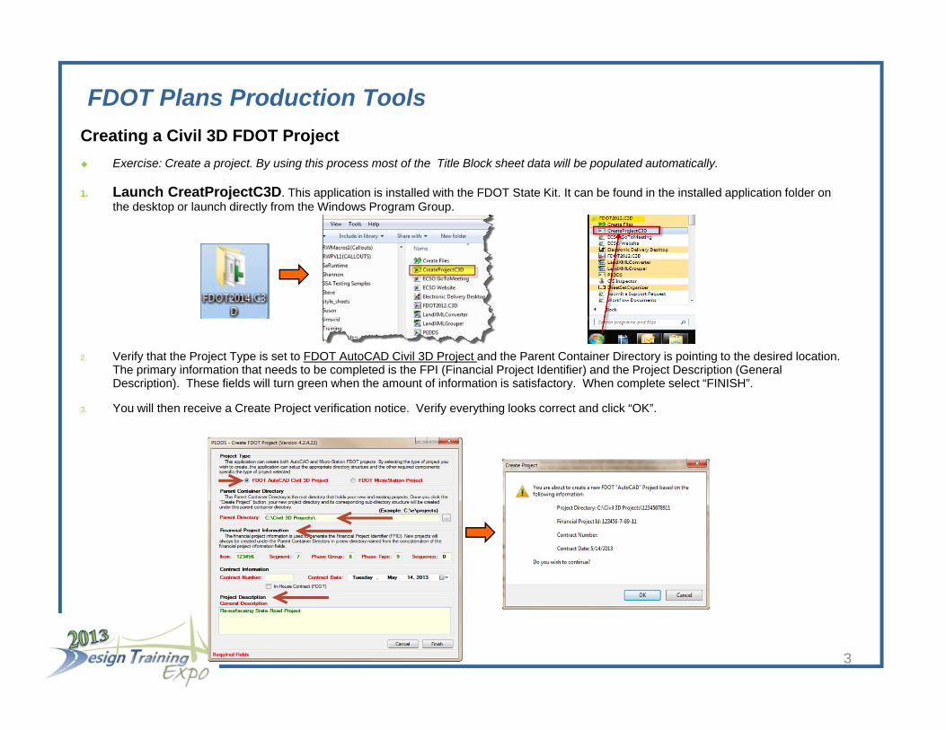
FDOT Plans Production ToolsCreating a Civil 3D FDOT Project Exercise: Create a project. By using this process most of the Title Block sheet data will be populated automatically.
1. Launch CreatProjectC3D. This application is installed with the FDOT State Kit. It can be found in the installed application folder on the desktop or launch directly from the Windows Program Group.
2. Verify that the Project Type is set to FDOT AutoCAD Civil 3D Project and the Parent Container Directory is pointing to the desired location. The primary information that needs to be completed is the FPI (Financial Project Identifier) and the Project Description (General Description). These fields will turn green when the amount of information is satisfactory. When complete select “FINISH”.
3. You will then receive a Create Project verification notice. Verify everything looks correct and click “OK”.
3
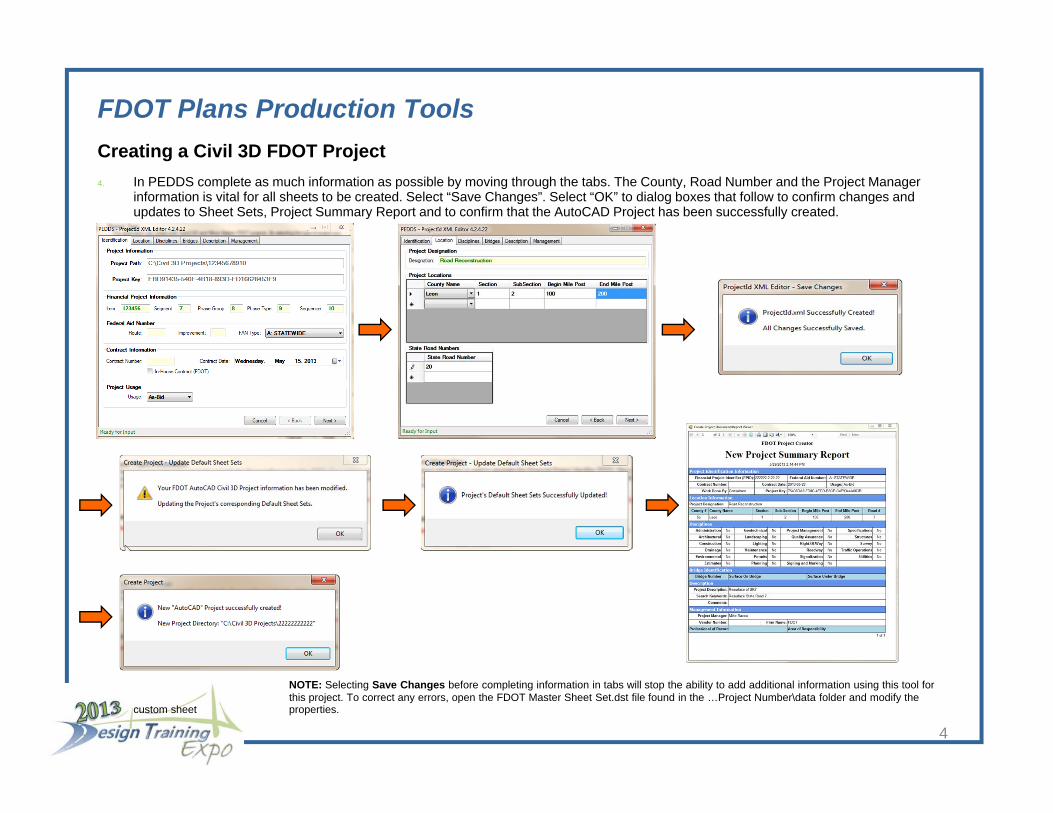
FDOT Plans Production ToolsCreating a Civil 3D FDOT Project4. In PEDDS complete as much information as possible by moving through the tabs. The County, Road Number and the Project Manager
information is vital for all sheets to be created. Select “Save Changes”. Select “OK” to dialog boxes that follow to confirm changes and updates to Sheet Sets, Project Summary Report and to confirm that the AutoCAD Project has been successfully created.
NOTE: Selecting Save Changes before completing information in tabs will stop the ability to add additional information using this tool for this project. To correct any errors, open the FDOT Master Sheet Set.dst file found in the …Project Number\data folder and modify the
custom sheet properties.
4

FDOT Plans Production ToolsCreating a Sheet Set (dst) fileThe Sheet Manager organizes, displays and manages collections of drawing sheets. Each sheet in a set is a layout in a drawing (DWG) file.
Exercise: Create a Sheet Set Manager file (dst) For sheet set data.
1. Access Sheet set Manager by clicking the Sheet Set Manager icon on the Home ribbon Pallets Tab.
2. Open the Sheet Set Manager and select the drop-down arrow to pick the “New Sheet Set…” option.
3. When the Create Sheet Set wizard opens, select to use “An example sheet set” then “Next”.
5
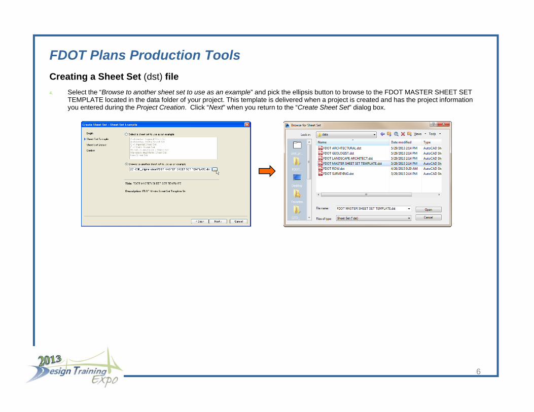
FDOT Plans Production ToolsCreating a Sheet Set (dst) file4. Select the “Browse to another sheet set to use as an example” and pick the ellipsis button to browse to the FDOT MASTER SHEET SET
TEMPLATE located in the data folder of your project. This template is delivered when a project is created and has the project information you entered during the Project Creation. Click “Next” when you return to the “Create Sheet Set” dialog box.
6

FDOT Plans Production ToolsCreating a Sheet Set (dst) file5. Name your Sheet Set then select the ellipsis button to navigate to your project location. Store the file in the \eng_data folder under the
corresponding discipline folder. At this point you will also have the opportunity to add any additional information that was missed at the beginning during the Create
Project setup. Select “Sheet Set Properties” to add or edit the Custom Properties.
6. Click “NEXT”, confirm the Sheet Set Preview setting and select “FINISH” when complete. Your new Sheet Set will display in the Sheet Set Manager dialog box.
7
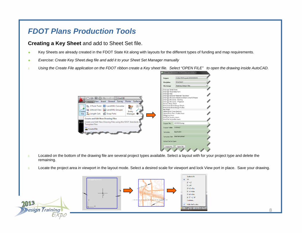
FDOT Plans Production ToolsCreating a Key Sheet and add to Sheet Set file. Key Sheets are already created in the FDOT State Kit along with layouts for the different types of funding and map requirements.
Exercise: Create Key Sheet.dwg file and add it to your Sheet Set Manager manually
1. Using the Create File application on the FDOT ribbon create a Key sheet file. Select “OPEN FILE” to open the drawing inside AutoCAD.
2. Located on the bottom of the drawing file are several project types available. Select a layout with for your project type and delete the remaining.
3. Locate the project area in viewport in the layout mode. Select a desired scale for viewport and lock View port in place. Save your drawing.
8

FDOT Plans Production ToolsCreating a Key Sheet and add to Sheet Set file. Exercise: Adding sheets manually to a Sheet Set file.
1. Right click on the component name for the Key Sheet and select “Import Layout as Sheet”.
2. The current drawing will already be in the list. You can load several additional drawings by selecting the “Browse for Drawing” option to import any other drawings with layouts you wish to add to the Sheet Set.
9

FDOT Plans Production ToolsCreating a Key Sheet and add to Sheet Set file.3. Select the layout(s) to be imported into the Sheet Set. Layouts not selected will not be available for electronic delivery through the Sheet
Set Organizer. Make sure that the Prefix sheet titles box is unchecked unless you want the file name prefixed to your layout.
4. Review the added layouts and select “Import Checked” to finish adding sheets.
10
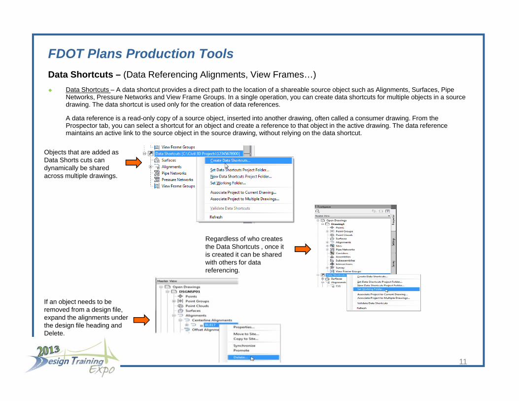
FDOT Plans Production ToolsData Shortcuts – (Data Referencing Alignments, View Frames…) Data Shortcuts – A data shortcut provides a direct path to the location of a shareable source object such as Alignments, Surfaces, Pipe
Networks, Pressure Networks and View Frame Groups. In a single operation, you can create data shortcuts for multiple objects in a source drawing. The data shortcut is used only for the creation of data references.
A data reference is a read-only copy of a source object, inserted into another drawing, often called a consumer drawing. From the Prospector tab, you can select a shortcut for an object and create a reference to that object in the active drawing. The data reference maintains an active link to the source object in the source drawing, without relying on the data shortcut.
Regardless of who creates the Data Shortcuts , once it is created it can be shared with others for data referencing.
If an object needs to be removed from a design file, expand the alignments under the design file heading and Delete.
Objects that are added as Data Shorts cuts can dynamically be shared across multiple drawings.
11

FDOT Plans Production ToolsData Shortcuts – (Data Referencing Alignments, View Frames…) Exercise: Add alignment to pavement design file. This exercise will assume that the alignment file has been created but not yet shared. We
are going to add an alignment to our Data shortcuts so we can access it in another drawing.
1. Open the ALGNRD01.dwg file found in the roadway folder of the project.
2. Zoom Extents (Type ZE on command line or double click mouse wheel) and save the file.
3. On the Toolspace Pallet, Prospector tab right click on the Data Shortcut(s) section and select “Set Working Folder…” and navigate to the project folder location (i.e. C:\E\projects). The path will display next to the Data Shortcuts title showing the first project with Data Shortcuts. Next right click again on Data Shortcut(s) and select “Set Working Folder…” and select the Name of your project from the list provided.
12

FDOT Plans Production ToolsData Shortcuts – (Data Referencing Alignments, View Frames…)4. On the Toolspace Pallet, Prospector tab right click on the Data Shortcut(s) section and select “Create Data Shortcuts…” and select your
Alignments. Click “OK”. Expand the Alignments sections to see your Alignments added to your Data Shortcuts.
13
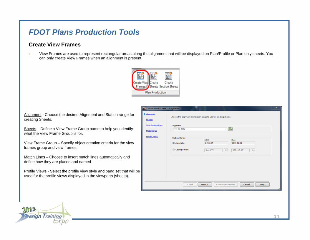
FDOT Plans Production ToolsCreate View Frames View Frames are used to represent rectangular areas along the alignment that will be displayed on Plan/Profile or Plan only sheets. You
can only create View Frames when an alignment is present.
Alignment - Choose the desired Alignment and Station range for creating Sheets.
Sheets – Define a View Frame Group name to help you identify what the View Frame Group is for.
View Frame Group – Specify object creation criteria for the view frames group and view frames.
Match Lines – Choose to insert match lines automatically and define how they are placed and named.
Profile Views - Select the profile view style and band set that will be used for the profile views displayed in the viewports (sheets).
14

FDOT Plans Production ToolsCreate View Frames wizard - (Clip Borders for Plan View Sheets) Before you can create view frames you must already have an alignment defined in your drawing.
Exercise: Reference Alignment from Data Shortcuts.
1. Create a new drawing called CLIPRD##.dwg using the FDOT Create File tool. Select the “Clip Borders” option from the list provided.
2. Right Click on Data Shortcuts and Data reference alignment into your new Drawing. In the “Create Alignment Reference” dialog box select the appropriate Alignment style and Alignment Label set from the pull down menus. Click “OK” when finished. Expand the “Alignments” tree in Toolspace palette to confirm your Alignment has been referenced. You can all Zoom Extents (ZE command) to view the alignementin model space.
15
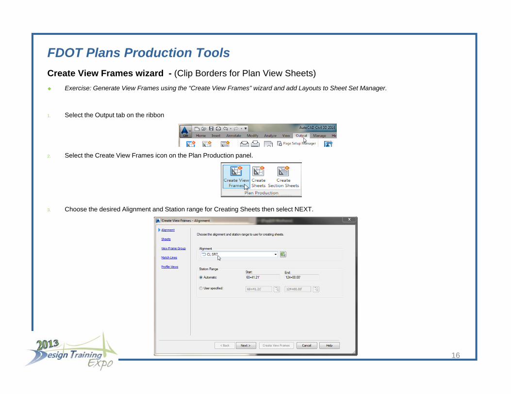
FDOT Plans Production ToolsCreate View Frames wizard - (Clip Borders for Plan View Sheets) Exercise: Generate View Frames using the “Create View Frames” wizard and add Layouts to Sheet Set Manager.
1. Select the Output tab on the ribbon
2. Select the Create View Frames icon on the Plan Production panel.
3. Choose the desired Alignment and Station range for Creating Sheets then select NEXT.
16
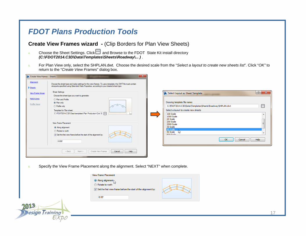
FDOT Plans Production ToolsCreate View Frames wizard - (Clip Borders for Plan View Sheets)4. Choose the Sheet Settings. Click and Browse to the FDOT State Kit install directory
(C:\FDOT2014.C3D\Data\Templates\Sheets\Roadway\... ) .
5. For Plan View only, select the SHPLAN.dwt. Choose the desired scale from the “Select a layout to create new sheets list”. Click “OK” to return to the “Create View Frames” dialog box.
6. Specify the View Frame Placement along the alignment. Select “NEXT” when complete.
17

FDOT Plans Production ToolsCreate View Frames wizard - (Clip Borders for Plan View Sheets)7. Here you will define a View Frame Group name to help you identify what the View Frame Group is for. For example Plan – 40 Scale<[View
Frame Group Alignment Name(CP]> The portion in brackets means that Civil 3D will automatically place the Alignment name in the View Frame Group name. The description is optional.
8. The Name, Style and Label have FDOT style already assigned to them.
9. Click “NEXT” to continue.
18

FDOT Plans Production ToolsCreate View Frames wizard - (Clip Borders for Plan View Sheets)10. Here you will Choose to insert match lines automatically and define how they are placed and named.
11. Choose the Positioning, Match Line Style, and Labels Styles that will define how your Match Lines will appear in your Drawings. FDOT styles have been provided for you.
12. Since we are creating Plan Views only, the Profile Views is grayed out. Click on “Create View Frames” to place Frames into the drawing.
13. Select the newly generated View Frames in model space and using the Grips, adjust the frames as needed.
19

FDOT Plans Production ToolsCreate View Frames wizard - (Clip Borders for Plan View Sheets)14. In order to share the View Frame with other drawings they need to be added to Data Shortcuts.
15. Right click on Data Shortcut(s) in the prospector and select “Create Data Shortcuts”. Select the View Frame Group name and click “OK”.
16. Select the objects for sharing, then select OK.
20

FDOT Plans Production ToolsCreate Sheets wizard - (Use to create Plan or Plan/Profile sheets and add to existing Sheet Set file) After you have used the Create View Frames wizard to create view frames, you can create sheets automatically using the Create Sheets
wizard.
Exercise: Generate Drawings for Plan Sheets
1. Create a new file called MTPLRD##.dwg using the FDOT Create File tool. Select the “Motif file for plan sheets”” option from the list provided. This file is used to combine the Design file, Topography file, Alignment data and the View Frame Group.
21

FDOT Plans Production ToolsCreate Sheets wizard - (Use to create Plan or Plan/Profile sheets and add to existing Sheet Set file)2. Attach Reference (xref) DSGNRD## and TOPORD## (Since drawings are going to be created from this file we want to use “Attachment
Method” only).
3. Create Data Reference for Alignments (Profile if creating Plan and Profiles) and View Frame Groups (Create Sheets will not work with out a View Frame Group). Select any other Data references if needed (Surfaces, Pipe Networks…).
22

FDOT Plans Production ToolsCreate Sheets Creates sheets for plotting from existing view frames.
CREATE SHEETS command (Output Ribbon Plans Production Tab).
Select CREATE SHEETS when finish
View Frame Group and Layouts – Choose the desired View Frame Group and output settings for Sheet layout Creation.
Sheet Set – Use these options to create a new sheet set or add to an existing sheet set. You can also specify storage location of the sheet set file association with the new or existing sheet set.
Select “Add to existing sheet set:” Select Roadway Plan.dst file located in the eng_data folder under the roadway folder.
Sheet file name: Plan <[View Frame Group Alignment Name]>
Data References - Select the data you want to reference in your sheets.
23

FDOT Plans Production ToolsCreate Sheets wizard - (Use to create Plan or Plan/Profile sheets and add to existing Sheet Set file) Exercise: Adding sheets using the Create Sheet wizard.
1. Run the Create Sheets Wizard from the Output Ribbon.
2. Select the the View Frame Group name. For Layout Creation settings, select how many layouts per drawing (10 or less is recommended) are created. Layout name ex: Plan <View Frame Group Alignment Name> <View Frame Start Station Value> to <View Frame End Station Value>. Make sure a North Arrow is selected. Click “Next”.
24
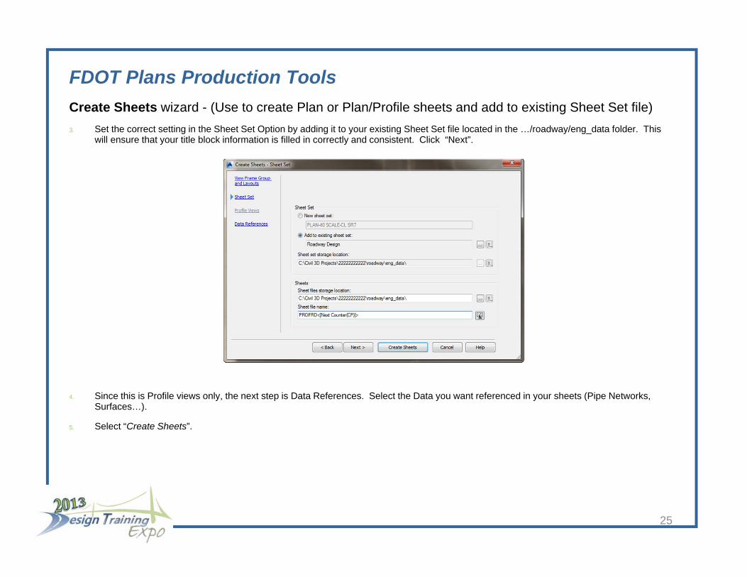
FDOT Plans Production ToolsCreate Sheets wizard - (Use to create Plan or Plan/Profile sheets and add to existing Sheet Set file)3. Set the correct setting in the Sheet Set Option by adding it to your existing Sheet Set file located in the …/roadway/eng_data folder. This
will ensure that your title block information is filled in correctly and consistent. Click “Next”.
4. Since this is Profile views only, the next step is Data References. Select the Data you want referenced in your sheets (Pipe Networks, Surfaces…).
5. Select “Create Sheets”.
25
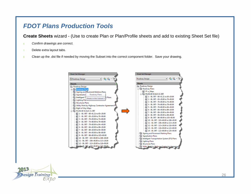
FDOT Plans Production ToolsCreate Sheets wizard - (Use to create Plan or Plan/Profile sheets and add to existing Sheet Set file)6. Confirm drawings are correct.
7. Delete extra layout tabs.
8. Clean up the .dst file if needed by moving the Subset into the correct component folder. Save your drawing.
26

FDOT Plans Production ToolsCreate Section Sheets wizard - (Use to create Cross Section Sheets and add to an existing Sheet Set file)
Create New Drawing to derive new Cross Section sheets from.
Exercise: Set up Sheet for Sample Lines and Cross Section Sheets
1. Select the Create File tool from the FDOT State Kit ribbon.
2. Select the ROADWAY CROSS-SECTIONS (rdxsrd##.dwt) and click OK.
27

FDOT Plans Production ToolsCreate Section Sheets wizard - (Use to create Cross Section Sheets and add to an existing Sheet Set file)
3. Create Data Reference for Alignment. Select any other Data references if needed (Surfaces, Pipe Networks…)
4. Attach Reference (xref) DSGNRD## and TOPORD## (Since drawings are going to be created from this file we want to use “Attachment Method” only).
28
FDOT Plans Production ToolsCreate Section Sheets wizard - (Use to create Cross Section Sheets and add to an existing Sheet Set file)
Create Sample Lines
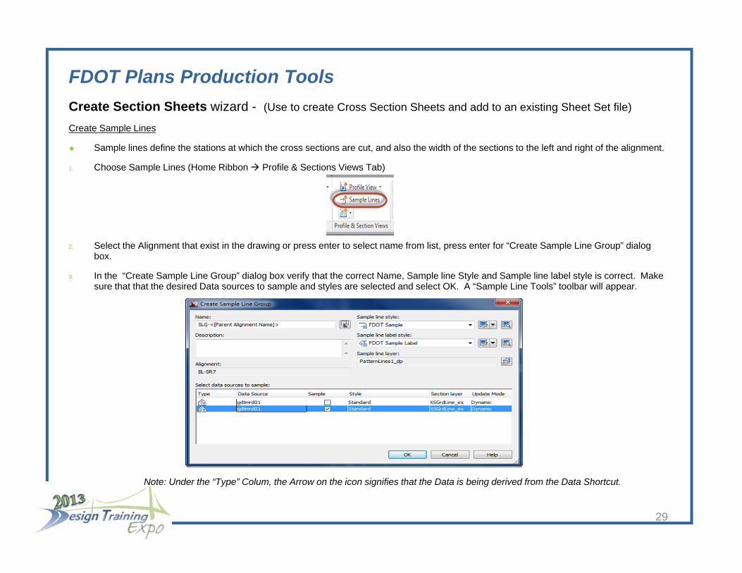
Sample lines define the stations at which the cross sections are cut, and also the width of the sections to the left and right of the alignment.
1. Choose Sample Lines (Home Ribbon Profile & Sections Views Tab)
2. Select the Alignment that exist in the drawing or press enter to select name from list, press enter for “Create Sample Line Group” dialog box.
3. In the “Create Sample Line Group” dialog box verify that the correct Name, Sample line Style and Sample line label style is correct. Make sure that that the desired Data sources to sample and styles are selected and select OK. A “Sample Line Tools” toolbar will appear.
29
Note: Under the “Type” Colum, the Arrow on the icon signifies that the Data is being derived from the Data Shortcut.

FDOT Plans Production ToolsCreate Section Sheets wizard - (Use to create Cross Section Sheets and add to an existing Sheet Set file)
4. Select “By Range of Station” from the “Sample Line Tools” Tool Bar.
5. Use the next dialog box to create sample lines along an alignment at a specified range of stations and Right, Left Swath Width settings. Click OK to finish. Examine the sample lines in Model Space. You can adjust Sample line location and swath lenths by selecting the lines and adjusting the grips accordingly. Save your Drawing.
30
FDOT Plans Production ToolsCreate Section Sheets wizard - (Use to create Cross Section Sheets and add to an existing Sheet Set file)
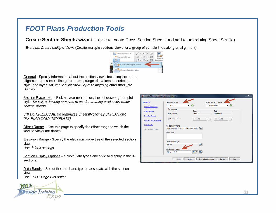
Exercise: Create Multiple Views (Create multiple sections views for a group of sample lines along an alignment).
General - Specify information about the section views, including the parent alignment and sample line group name, range of stations, description, style, and layer. Adjust “Section View Style” to anything other than _No Display.
Section Placement – Pick a placement option, then choose a group plot style. Specify a drawing template to use for creating production-ready section sheets.
C:\FDOT2012.C3D\Data\templates\Sheets\Roadway\SHPLAN.dwt (For PLAN ONLY TEMPLATE)
Offset Range – Use this page to specify the offset range to which the section views are drawn.
Elevation Range - Specify the elevation properties of the selected section view.Use default settings
Section Display Options – Select Data types and style to display in the X-sections.
Data Bands – Select the data band type to associate with the section view.Use FDOT Page Plot option
31
FDOT Plans Production ToolsCreate Section Sheets wizard - (Use to create Cross Section Sheets and add to an existing Sheet Set file)
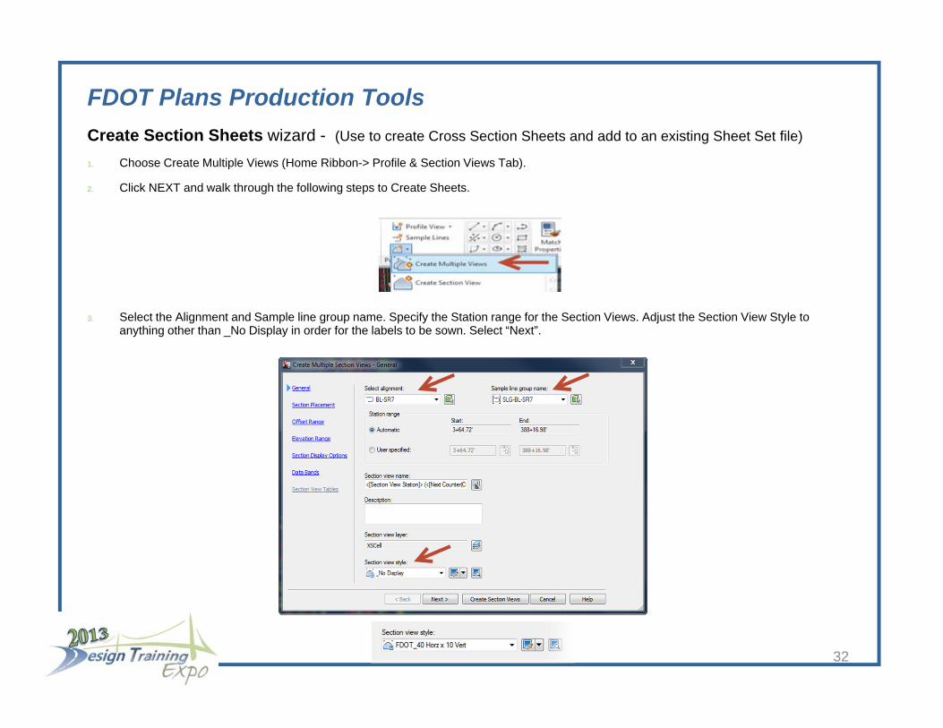
1. Choose Create Multiple Views (Home Ribbon-> Profile & Section Views Tab).
2. Click NEXT and walk through the following steps to Create Sheets.
3. Select the Alignment and Sample line group name. Specify the Station range for the Section Views. Adjust the Section View Style to anything other than _No Display in order for the labels to be sown. Select “Next”.
32
FDOT Plans Production ToolsCreate Section Sheets wizard - (Use to create Cross Section Sheets and add to an existing Sheet Set file)
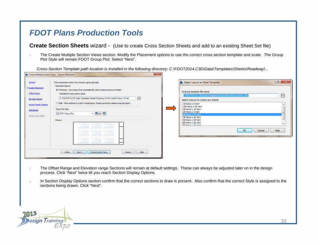
4. The Create Multiple Section Views section. Modify the Placement options to use the correct cross section template and scale. The Group Plot Style will remain FDOT Group Plot. Select “Next”.
5. The Offset Range and Elevation range Sections will remain at default settings. These can always be adjusted later on in the design process. Click “Next” twice till you reach Section Display Options.
6. In Section Display Options section confirm that the correct sections to draw is present. Also confirm that the correct Style is assigned to the sections being drawn. Click “Next”.
33
Cross-Section Template path location is installed in the following directory: C:\FDOT2014.C3D\Data\Templates\Sheets\Roadway\...

FDOT Plans Production ToolsCreate Section Sheets wizard - (Use to create Cross Section Sheets and add to an existing Sheet Set file)
7. On the Data Bands sections, confirm that FDOT Page Plot is selected for the band set and that the location is set to Bottom of section view.
8. Select “Create Section Views”.
9. When prompted at the command to Identify section view origin, select a point away from the project, preferably to the right of the project. This will prevent your sections from overlapping the project.
34

FDOT Plans Production ToolsCreate Section Sheets wizard - (Use to create Cross Section Sheets and add to an existing Sheet Set file)
Create Layouts for plotting section views. Use this dialog box to create paper space layouts that contain the section views in your drawing
1. Execute the CREATE SECTION SHEETS command. (Output Ribbon Plan Production Tab)
.
2. Select Alignment name, Sample Line group name and Section view group Name.
3. Layout Settings - Name that’s automatically created and assigned to layout tabs. Ex: Section Sheet-<[Parent Alignment]> - <[Sample Line Group Name]>
4. Sheet Set – Add to Existing sheet set: Road Way Plans
5. Sheet set storage location: ….\eng_data\ folder. (Choose Roadway Design.dst file). Click “Create Sheets” and “OK” to confirm that your drawing will be saved. Sheet Set Manager will launch. Click on your section view group sheets to view your drawings.
35

FDOT Plans Production ToolsAny Questions?
36
Mike Racca
CADD APPLICATIONS SUPPORT
Florida Department of Transportation
Email: [email protected]
Phone: 850-245-1631