FDOT Plans Production Tools Part 1 of 2 · FDOT Plans Production Tools Part 1 of 2 ......
14
FDOT Plans Production Tools Part 1 of 2 This course helps you automate the creation of Sheets, Plan, Plan/Profile and Cross Section sheets. FDOT State Kit for AutoCAD Civil 3D 2014 Mike Racca CADD APPLICATIONS SUPPORT Florida Department of Transportation (ECSO) Email: [email protected] Phone: 850-245-1621
Transcript of FDOT Plans Production Tools Part 1 of 2 · FDOT Plans Production Tools Part 1 of 2 ......

FDOT Plans Production Tools
Part 1 of 2This course helps you automate the creation of Sheets, Plan, Plan/Profile and Cross Section sheets.
FDOT State Kit for AutoCAD Civil 3D 2014
Mike Racca
CADD APPLICATIONS SUPPORT
Florida Department of Transportation (ECSO)
Email: [email protected]
Phone: 850-245-1621

FDOT Plans Production Tools The workflows created for use with Florida Department of Transportation (FDOT) plans are dependent on the following:
Create a Civil 3D FDOT Project. - Information from the creation of the project is carried into the sheet Title Blocks.
Creating a Sheet Set (dst) file - Displays and organizes named collections of drawings.
Create a Key Sheet – Add Key Sheet to Sheet Set file.
Data Shortcuts – Used only for the creation of data references such as Alignments, Surfaces, Pipe networks, and View Frames…
Create View Frames wizard (Clip Borders for Plan and Plan/Profile View Sheets)
Create Sheets wizard (Use to create Plan or Plan/Profile sheets and add to existing Sheet Set file)
Create Section Sheets wizard (Use to create Cross Section Sheets and add to an existing Sheet Set file)
Create View frames are used to represent rectangular areas along the alignment that will be displayed on plan/profile or plan-only sheets. Before you create view frames, an alignment must already exist in your drawing. Depending on the type of sheetsyou want to produce (plan and profile or profile only), you may also need to have a profile already created. If you are creating a plan only view frame (or sheet set), then you do not need to have a profile in the drawing.
*Command will not execute with out an alignment.
Create Sheets wizard to quickly create sheets for construction documents (plans) from View Frames.
*Command will not execute with out an alignment.
Create Section Sheets command to create layouts for plotting section views and Sheets. As a prerequisite to using the Create Section Sheets command, you must use the “Sample Lines” and “Create Multiple Views” command to generate section views before you can Create Section Sheets.
*Requires and Alignment, Sample Line Group Name and Section View Group.
2

Creating a Civil 3D FDOT Project
Exercise: Create a project. By using this process most of the Title Block sheet data will be populated automatically.
3
FDOT Plans Production Tools
1 2 3

Creating a Sheet Set (dst) file
The Sheet Manager organizes, displays and manages collections of drawing sheets. Each sheet in a set is a layout in a drawing (DWG) file.
4
FDOT Plans Production Tools
Layouts become sheets in Sheet Set Manager

Creating a Key Sheet and add to Sheet Set file.
Key Sheets are already created in the FDOT State Kit along with layouts for the different types of funding and map requirements.
Exercise: Create a Key Sheet.dwg file and add it manually to the Sheet Set (DST) file.
5
FDOT Plans Production Tools
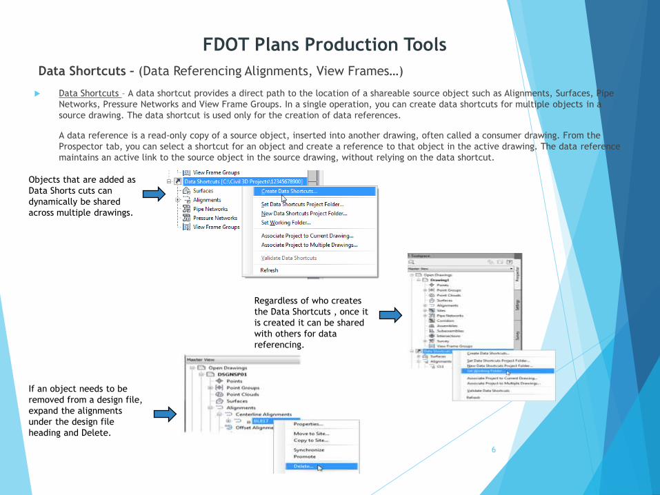
Data Shortcuts – (Data Referencing Alignments, View Frames…)
Data Shortcuts – A data shortcut provides a direct path to the location of a shareable source object such as Alignments, Surfaces, Pipe
Networks, Pressure Networks and View Frame Groups. In a single operation, you can create data shortcuts for multiple objects in a
source drawing. The data shortcut is used only for the creation of data references.
A data reference is a read-only copy of a source object, inserted into another drawing, often called a consumer drawing. From the
Prospector tab, you can select a shortcut for an object and create a reference to that object in the active drawing. The data reference
maintains an active link to the source object in the source drawing, without relying on the data shortcut.
6
Regardless of who creates
the Data Shortcuts , once it
is created it can be shared
with others for data
referencing.
If an object needs to be
removed from a design file,
expand the alignments
under the design file
heading and Delete.
Objects that are added as
Data Shorts cuts can
dynamically be shared
across multiple drawings.
FDOT Plans Production Tools

Create View Frames
View Frames are used to represent rectangular areas along the alignment that will be displayed on Plan/Profile or Plan only sheets.
You can only create View Frames when an alignment is present. Before you can create View frames your drawing must contain an
alignment.
7
Alignment - Choose the desired Alignment and Station range for
creating Sheets.
Sheets – Define a View Frame Group name to help you identify
what the View Frame Group is for.
View Frame Group – Specify object creation criteria for the view
frames group and view frames.
Match Lines – Choose to insert match lines automatically and
define how they are placed and named.
Profile Views - Select the profile view style and band set that will
be used for the profile views displayed in the viewports (sheets).
FDOT Plans Production Tools

Create File for View Frames - (Used as a source Drawing to House and Create View Frames)
Exercise: Generate Drawings for View Frames
1. Use the “Clip Borders” template to create a new file called CLIPRD##.dwg using the FDOT Create File tool. This file is used to combine
the View Frames and Alignment data.
8
FDOT Plans Production Tools

Create File for Plan Sheet Motif - (Use to create Plan or Plan/Profile sheets and add to existing Sheet Set file)
Exercise: Generate Drawings for Plan Sheets.
1. Use the “Motif File for Plan Sheets” template to create a new file called MTPLRD##.dwg using the FDOT Create File tool. This file is
used to combine the Design file, Topography file, Alignment data and the View Frame Group.
9
FDOT Plans Production Tools

Create Sheets
Creates sheets for plotting from existing view frames.
CREATE SHEETS command (Output Ribbon Plans Production Tab).
Select CREATE SHEETS when finish
10
View Frame Group and Layouts – Choose the desired View Frame Group
and output settings for Sheet layout Creation.
Sheet Set – Use these options to create a new sheet set or add to an
existing sheet set. You can also specify storage location of the sheet
set file association with the new or existing sheet set.
Select “Add to existing sheet set:” Select Roadway Plan.dst file located
in the eng_data folder under the roadway folder.
Sheet file name: Plan <[View Frame Group Alignment Name]>
Data References - Select the data you want to reference in your sheets.
FDOT Plans Production Tools

Create Section Sheets wizard - (Use to create Cross Section Sheets and add to an existing Sheet Set file)
Create Sample Lines
Sample lines define the stations at which the cross sections are cut, and also the width of the sections to the left and right of the
alignment.
11
FDOT Plans Production Tools

Create Section Sheets wizard - (Use to create Cross Section Sheets and add to an existing Sheet Set file)
Exercise: Create Multiple Views (Create multiple sections views for a group of sample lines along an alignment).
12
General - Specify information about the section views, including the
parent alignment and sample line group name, range of stations,
description, style, and layer. Adjust “Section View Style” to anything
other than _No Display.
Section Placement – Pick a placement option, then choose a group plot
style. Specify a drawing template to use for creating production-ready
section sheets.
C:\FDOT2012.C3D\Data\templates\Sheets\Roadway\SHPLAN.dwt
(For PLAN ONLY TEMPLATE)
Offset Range – Use this page to specify the offset range to which the
section views are drawn.
Elevation Range - Specify the elevation properties of the selected
section view.
Use default settings
Section Display Options – Select Data types and style to display in the X-
sections.
Data Bands – Select the data band type to associate with the section
view.
Use FDOT Page Plot option
FDOT Plans Production Tools

Create Section Sheets wizard - (Use to create Cross Section Sheets and add to an existing Sheet Set file)
Create Layouts for plotting section views. Use this dialog box to create paper space layouts that contain the section views in your drawing
13
FDOT Plans Production Tools

Any Questions?
14
Mike Racca
CADD APPLICATIONS SUPPORT
Florida Department of Transportation
Email: [email protected]
Phone: 850-245-1621
FDOT Plans Production Tools