Exploring Boundaries in Game Processing · game console that contains several special processors...
53
Exploring Boundaries in Game Processing M.C.N. Oostindie Author: M.C.N. Oostindie Id: 431407 Supervisors: Prof. Dr. H. Corporaal Dr. Ir. A.A. Basten Ir. S. Stuijk Issued: 11/2005
Transcript of Exploring Boundaries in Game Processing · game console that contains several special processors...
Exploring Boundaries inGame Processing
M.C.N. Oostindie
Author: M.C.N. OostindieId: 431407Supervisors: Prof. Dr. H. Corporaal
Dr. Ir. A.A. BastenIr. S. Stuijk
Issued: 11/2005

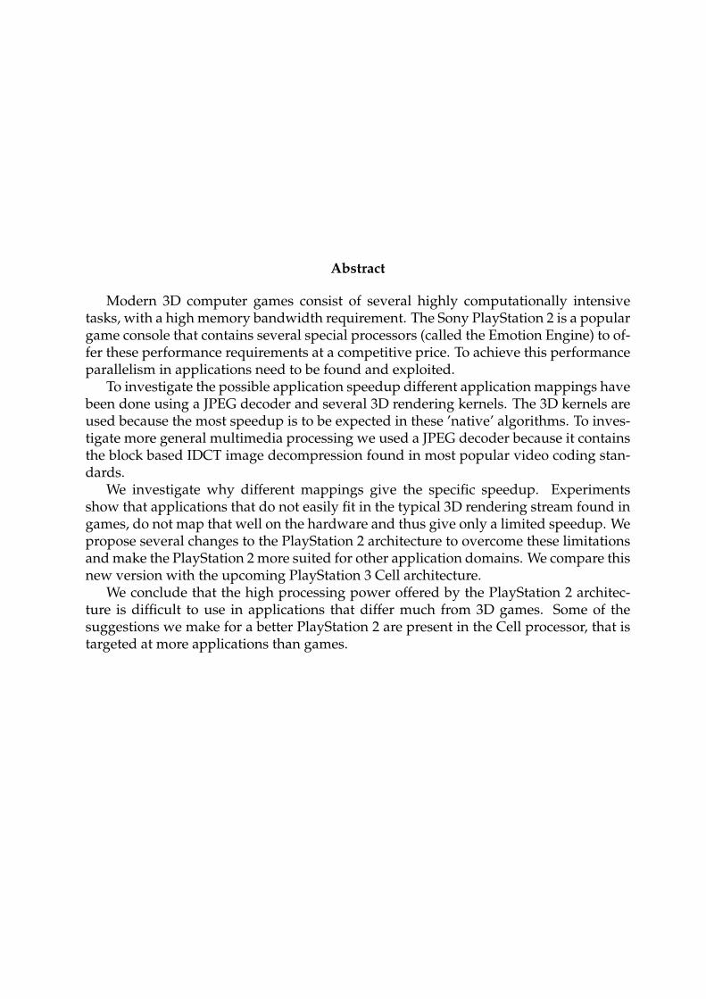
Abstract
Modern 3D computer games consist of several highly computationally intensivetasks, with a high memory bandwidth requirement. The Sony PlayStation 2 is a populargame console that contains several special processors (called the Emotion Engine) to of-fer these performance requirements at a competitive price. To achieve this performanceparallelism in applications need to be found and exploited.
To investigate the possible application speedup different application mappings havebeen done using a JPEG decoder and several 3D rendering kernels. The 3D kernels areused because the most speedup is to be expected in these ’native’ algorithms. To inves-tigate more general multimedia processing we used a JPEG decoder because it containsthe block based IDCT image decompression found in most popular video coding stan-dards.
We investigate why different mappings give the specific speedup. Experimentsshow that applications that do not easily fit in the typical 3D rendering stream found ingames, do not map that well on the hardware and thus give only a limited speedup. Wepropose several changes to the PlayStation 2 architecture to overcome these limitationsand make the PlayStation 2 more suited for other application domains. We compare thisnew version with the upcoming PlayStation 3 Cell architecture.
We conclude that the high processing power offered by the PlayStation 2 architec-ture is difficult to use in applications that differ much from 3D games. Some of thesuggestions we make for a better PlayStation 2 are present in the Cell processor, that istargeted at more applications than games.


Contents
1 Introduction 71.1 Problem statement . . . . . . . . . . . . . . . . . . . . . . . . . . . . . . . . 71.2 Objectives . . . . . . . . . . . . . . . . . . . . . . . . . . . . . . . . . . . . . 81.3 Related work . . . . . . . . . . . . . . . . . . . . . . . . . . . . . . . . . . . . 81.4 Overview . . . . . . . . . . . . . . . . . . . . . . . . . . . . . . . . . . . . . . 8
2 Application domain 92.1 MPEG Video decoding . . . . . . . . . . . . . . . . . . . . . . . . . . . . . . 9
2.1.1 VLD . . . . . . . . . . . . . . . . . . . . . . . . . . . . . . . . . . . . 102.1.2 Inverse Quantizer . . . . . . . . . . . . . . . . . . . . . . . . . . . . . 102.1.3 IDCT . . . . . . . . . . . . . . . . . . . . . . . . . . . . . . . . . . . . 102.1.4 Motion Compensation . . . . . . . . . . . . . . . . . . . . . . . . . . 112.1.5 Colour Conversion . . . . . . . . . . . . . . . . . . . . . . . . . . . . 122.1.6 Conclusion . . . . . . . . . . . . . . . . . . . . . . . . . . . . . . . . 13
2.2 3D Graphics rendering . . . . . . . . . . . . . . . . . . . . . . . . . . . . . . 142.2.1 3D graphics pipeline . . . . . . . . . . . . . . . . . . . . . . . . . . . 142.2.2 Homogeneous transformations . . . . . . . . . . . . . . . . . . . . . 142.2.3 Conclusion . . . . . . . . . . . . . . . . . . . . . . . . . . . . . . . . 16
3 PS2 architecture description 173.1 R5900 Emotion Engine CPU core . . . . . . . . . . . . . . . . . . . . . . . . 17
3.1.1 MIPS core . . . . . . . . . . . . . . . . . . . . . . . . . . . . . . . . . 183.1.2 Floating Point Unit . . . . . . . . . . . . . . . . . . . . . . . . . . . . 193.1.3 Vector Units (VU0 and VU1) . . . . . . . . . . . . . . . . . . . . . . 193.1.4 Differences from IEEE 754. . . . . . . . . . . . . . . . . . . . . . . . 203.1.5 IPU . . . . . . . . . . . . . . . . . . . . . . . . . . . . . . . . . . . . . 213.1.6 DRAMC . . . . . . . . . . . . . . . . . . . . . . . . . . . . . . . . . . 213.1.7 Main Bus . . . . . . . . . . . . . . . . . . . . . . . . . . . . . . . . . . 213.1.8 Graphics Interface . . . . . . . . . . . . . . . . . . . . . . . . . . . . 22
3.2 Graphics Synthesizer . . . . . . . . . . . . . . . . . . . . . . . . . . . . . . . 223.3 IOP . . . . . . . . . . . . . . . . . . . . . . . . . . . . . . . . . . . . . . . . . 233.4 Software and tools . . . . . . . . . . . . . . . . . . . . . . . . . . . . . . . . 24
3
CONTENTS
4 Parallelism in micro-architectures 254.1 Architecture design space . . . . . . . . . . . . . . . . . . . . . . . . . . . . 254.2 Examples . . . . . . . . . . . . . . . . . . . . . . . . . . . . . . . . . . . . . . 27
4.2.1 CISC . . . . . . . . . . . . . . . . . . . . . . . . . . . . . . . . . . . . 274.2.2 RISC . . . . . . . . . . . . . . . . . . . . . . . . . . . . . . . . . . . . 274.2.3 Pentium 4 . . . . . . . . . . . . . . . . . . . . . . . . . . . . . . . . . 274.2.4 TriMedia . . . . . . . . . . . . . . . . . . . . . . . . . . . . . . . . . . 284.2.5 Imagine Stream Architecture . . . . . . . . . . . . . . . . . . . . . . 28
4.3 Conclusion . . . . . . . . . . . . . . . . . . . . . . . . . . . . . . . . . . . . . 29
5 Mappings, experiments, results 315.1 Test applications . . . . . . . . . . . . . . . . . . . . . . . . . . . . . . . . . . 31
5.1.1 JPEG overview . . . . . . . . . . . . . . . . . . . . . . . . . . . . . . 315.1.2 3D Perspective Matrix Transformation . . . . . . . . . . . . . . . . . 32
5.2 Experiments . . . . . . . . . . . . . . . . . . . . . . . . . . . . . . . . . . . . 335.2.1 DTSE . . . . . . . . . . . . . . . . . . . . . . . . . . . . . . . . . . . . 335.2.2 JPEG . . . . . . . . . . . . . . . . . . . . . . . . . . . . . . . . . . . . 345.2.3 Conclusions . . . . . . . . . . . . . . . . . . . . . . . . . . . . . . . . 365.2.4 3D Perspective Matrix Transformation . . . . . . . . . . . . . . . . . 37
5.3 Conclusion . . . . . . . . . . . . . . . . . . . . . . . . . . . . . . . . . . . . . 37
6 PS2b: a better PS2 396.1 Hardware . . . . . . . . . . . . . . . . . . . . . . . . . . . . . . . . . . . . . 396.2 Software . . . . . . . . . . . . . . . . . . . . . . . . . . . . . . . . . . . . . . 416.3 Conclusion . . . . . . . . . . . . . . . . . . . . . . . . . . . . . . . . . . . . . 41
7 PS3: overview of the Cell architecture 437.1 The Cell Processor . . . . . . . . . . . . . . . . . . . . . . . . . . . . . . . . . 43
7.1.1 Synergistic Processor Unit . . . . . . . . . . . . . . . . . . . . . . . . 437.1.2 Memory Flow Controller . . . . . . . . . . . . . . . . . . . . . . . . 447.1.3 Memory and I/O . . . . . . . . . . . . . . . . . . . . . . . . . . . . . 447.1.4 Element Interconnect Bus . . . . . . . . . . . . . . . . . . . . . . . . 457.1.5 Parallelism . . . . . . . . . . . . . . . . . . . . . . . . . . . . . . . . . 45
7.2 Comparison between the Cell and the PS2b . . . . . . . . . . . . . . . . . . 457.2.1 Synergistic Processor Units vs. Vector Units . . . . . . . . . . . . . . 457.2.2 Image Processing Unit . . . . . . . . . . . . . . . . . . . . . . . . . . 467.2.3 Crypto accelerator . . . . . . . . . . . . . . . . . . . . . . . . . . . . 467.2.4 Programming . . . . . . . . . . . . . . . . . . . . . . . . . . . . . . . 46
7.3 Conclusion . . . . . . . . . . . . . . . . . . . . . . . . . . . . . . . . . . . . . 46
8 Conclusions and future work 478.1 Conclusions . . . . . . . . . . . . . . . . . . . . . . . . . . . . . . . . . . . . 478.2 Future work . . . . . . . . . . . . . . . . . . . . . . . . . . . . . . . . . . . . 47
4

CONTENTS
A Glossary 49
Bibliography 51
5

CONTENTS
6
Chapter 1
Introduction
In the field of consumer electronics there is a large, still growing, market for sophisti-cated multimedia applications. The computer games industry, with big players such asSony, Nintendo and recently also Microsoft has a traditional leading role in deliveringnew state of the art platforms. In the race for the most flashing 3D graphics and realisticgameplay they deliver very powerful game consoles at low costs yet still have a longlifetime. Most consoles are around for 6 years before a new generation is introduced.
To build a system with such specifications (the PlayStation 2 can perform 6.2 GFLOPSand has an internal bus bandwidth of 3.6GB/s), a special platform design is needed. Astandard desktop computer will generally not be sufficient, being either too slow or tooexpensive. The exception is the X-Box by Microsoft, which was almost a normal Intel PCand has about the same performance as the older PlayStation 2. They did this howeverto enter the market quickly by using an existing design instead of starting from scratch.The console is already being replaced after only 4 years.
The remainder of this chapter is organised as follows: In Section 1.1 we will formu-late the problem statement. The objectives of this thesis are the presented in Section 1.2.Related work is listed in Section 1.3. An overview of the structure of this document ispresented in Section 1.4.
1.1 Problem statement
At the introduction of the PlayStation 2, in 1999, the console was hyped to have theprocessing power of super computers while at the same time being much cheaper thannormal desktop PCs. The question rises, while the PlayStation 2 definitely has a lot ofprocessing power, why it didn’t appear in some form or another on the desktop. Untilnow, there hasn’t been another instantiation of the architecture, and since its successor,the PlayStation 3, is bound to be released, it is highly unlikely that there will ever beone.
7
1.4 CHAPTER 1. INTRODUCTION
1.2 Objectives
We will investigate the PlayStation 2 architecture, what possibilities there are for highperformance processing and in what kind of applications the can actually be achieved.We will present an improved version of the PlayStation 2, and compare this virtualarchitecture with the PlayStation 3/Cell architecture.
1.3 Related work
In [11] the possibilities to use the PlayStation 2 for scientific computing (in chemistry).They achieved some speedup, but no dramatic improvements. They point to OperatingSystem overhead and limited memory as the main bottlenecks.
1.4 Overview
The outline of this Report is as follows: We first describe the Application domain we areinterested in in Chapter 2. Chapter 3 discusses the PlayStation 2 architecture in detail.In Chapter 4 we explain different techniques to increase the computational power ofprocessors using different forms of parallelism. We explain where the PlayStation 2 fitsin the picture. InChapter 5 we investigate the actual performance that can be achievedon the PlayStation 2. We do this by mapping several kernels (small programs) on ar-chitecture. The results of these experiments are presented and explain why the specificperformance is achieved. We Investigate why the performance not always meets ourexpectations. In Chapter 6 we suggest improvements on the PlayStation 2 architectureto increase the performance of the platform. We compare these suggestions in Chapter 7to the new PlayStation 3 Cell architecture. Finally, in Chapter 8 the work is summarizedand conclusions are drawn. Recommendations for future work are given. Commonabbreviations are explained in the glossary, Appendix A.
8
Chapter 2
Application domain
In this chapter we will describe two types of application domains which are both verycommon and computational intensive inside multimedia processing. The first is MPEG-2 video decoding, which is a block based video coding standard. It is a popular videocoding standard, being the format of choice for DVD and satellite stations. The secondapplication are the drawing of real-time 3D graphics. The 3D environments found inmost current computer games require many operations for each pixel inside the screento create a realistic 2D image.
2.1 MPEG Video decoding
MPEG video is a block based video coding standard. A video stream consists of a se-quence of frames, which are divided into blocks of 8 × 8 pixels each. Both spatial andtemporal redundancies are used to reduce the required information to describe eachframe.
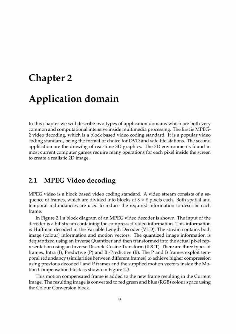
In Figure 2.1 a block diagram of an MPEG video decoder is shown. The input of thedecoder is a bit-stream containing the compressed video information. This informationis Huffman decoded in the Variable Length Decoder (VLD). The stream contains bothimage (colour) information and motion vectors. The quantized image information isdequantized using an Inverse Quantizer and then transformed into the actual pixel rep-resentation using an Inverse Discrete Cosine Transform (IDCT). There are three types offrames, Intra (I), Predictive (P) and Bi-Predictive (B). The P and B frames exploit tem-poral redundancy (similarities between different frames) to achieve higher compressionusing previous decoded I and P frames and the supplied motion vectors inside the Mo-tion Compensation block as shown in Figure 2.3.
This motion compensated frame is added to the new frame resulting in the CurrentImage. The resulting image is converted to red green and blue (RGB) colour space usingthe Colour Conversion block.
9
2.1 CHAPTER 2. APPLICATION DOMAIN
MotionCompensation
ReferenceImages
CurrentImage
VLD IDCTInverseQuantizer
ColourConversion
Bitstream
RGB output
Figure 2.1: Block diagram of an MPEG video decoder.
2.1.1 VLD
The first step in decoding an MPEG bitstream is decompressing the bitstream in 8 bitquantized DCT-coefficients. The compressed values have a variable length rangingfrom 1 to 16 bits, with an average length much lower than 8 bits for each 8 bit value.
2.1.2 Inverse Quantizer
The decoded DCT coefficients that are quantized, and need to be dequantized. Thedequantizing consists multiplying every coefficient with a specific constant, which isunique to every position in the 8 × 8 block. The dequantizing process thus involveslooking up of a constant and multiplying it with the decoded coefficient, totalling 64loads and multiplications per 8× 8 block.
2.1.3 IDCT
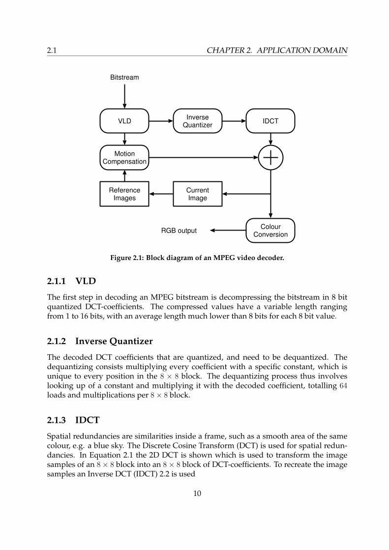
Spatial redundancies are similarities inside a frame, such as a smooth area of the samecolour, e.g. a blue sky. The Discrete Cosine Transform (DCT) is used for spatial redun-dancies. In Equation 2.1 the 2D DCT is shown which is used to transform the imagesamples of an 8× 8 block into an 8× 8 block of DCT-coefficients. To recreate the imagesamples an Inverse DCT (IDCT) 2.2 is used
10
CHAPTER 2. APPLICATION DOMAIN 2.1
S(u, v) =C(v)
2
C(u)
2
7∑y=0
7∑x=0
s(x, y) cos(2x + 1)uπ
16cos
(2y + 1)vπ
16(2.1)
s(x, y) =7∑
v=0
C(v)
2
7∑u=0
C(u)
2S(u, v) cos
(2x + 1)uπ
16cos
(2y + 1)vπ
16(2.2)
All the cosines are constant values, which can be pre-calculated. The meaning of thesymbols in Equations 2.1 and 2.2 are
C(x) =1√2, (x = 0)
C(x) = 1, (x > 0)
s(x, y) = 2D sample valueS(u, v) = 2D DCT coefficient
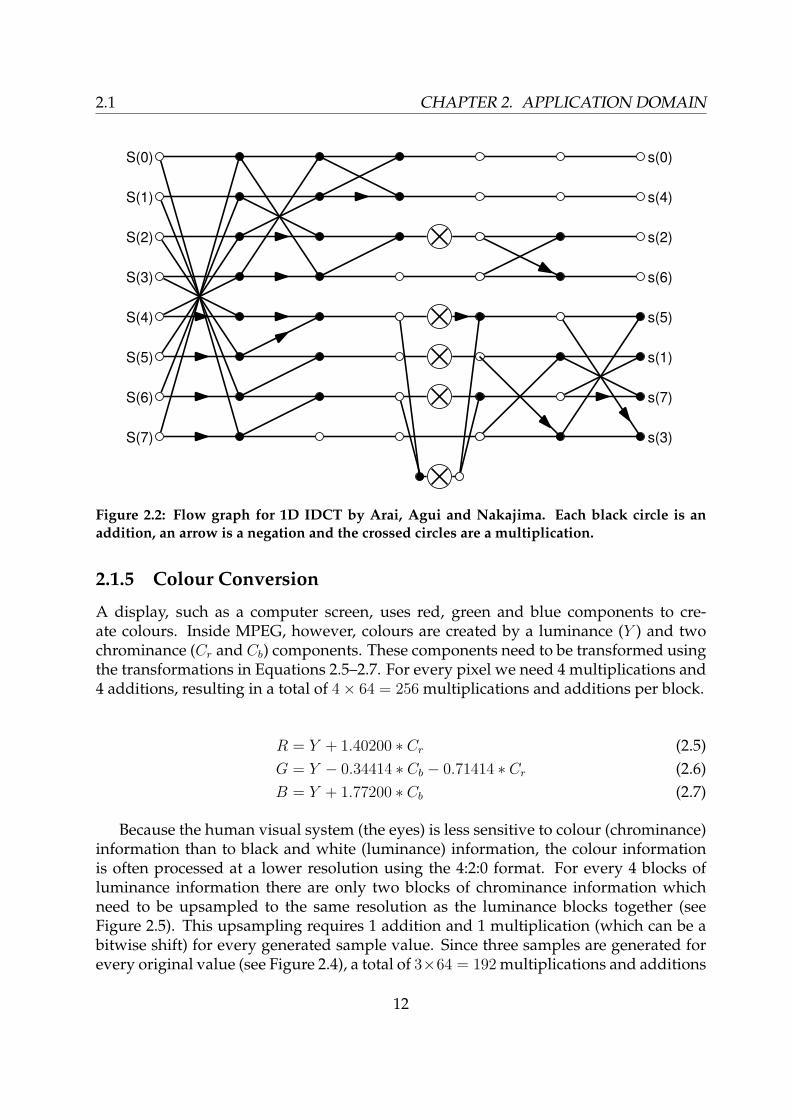
Because the 2D IDCT is separable, it can be computed by applying two times eight1D IDCTs sequentially, one in the horizontal (row) direction and one in the vertical (col-umn) direction (see Equation 2.3). This reduces the number of operations by a factor offour. The cosines and the constants C(u) in a 1D IDCT (Equation 2.4) can be combined.The resulting transform requires 64 multiplications and 56 additions, or 1024 multipli-cations and 896 additions for each 8 × 8 block, which can then be dequantized. Muchresearch has been done on implementations using less operations, where the most opti-mal known is published by Arai, Agui and Nakajima (their paper is in Japanese, how-ever, an English description can be found in [8]). Their implementation (see Figure 2.2)requires only 13 multiplications and 29 additions for each 1D IDCT. When dequantiza-tion has to be performed afterwards, 8 of the multiplications can be combined with thedequantization, which leaves only 5 multiplications for each 1D IDCT.
s(y, x) =
[7∑
v=0
C(v)
2cos
(2y + 1)vπ
16
] [7∑
u=0
C(u)
2S(v, u) cos
(2x + 1)uπ
16
](2.3)
s(x) =7∑
u=0
C(u)
2S(u) cos
(2x + 1)uπ
16(2.4)
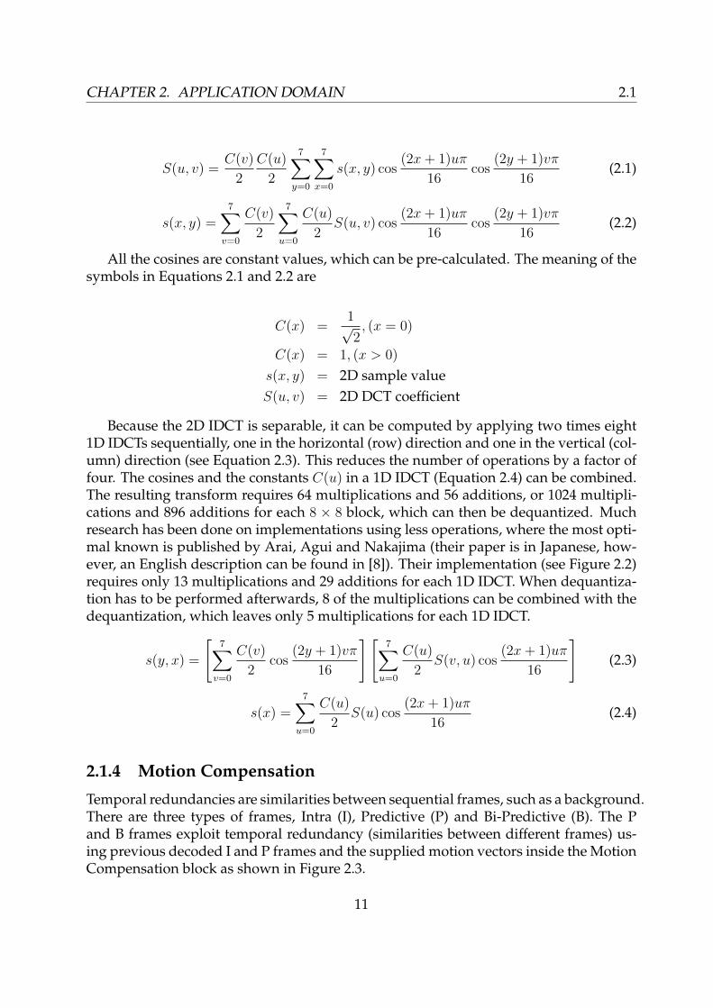
2.1.4 Motion Compensation
Temporal redundancies are similarities between sequential frames, such as a background.There are three types of frames, Intra (I), Predictive (P) and Bi-Predictive (B). The Pand B frames exploit temporal redundancy (similarities between different frames) us-ing previous decoded I and P frames and the supplied motion vectors inside the MotionCompensation block as shown in Figure 2.3.
11
2.1 CHAPTER 2. APPLICATION DOMAIN
S(0)
S(1)
S(2)
S(3)
S(4)
S(5)
S(6)
S(7)
s(0)
s(4)
s(2)
s(6)
s(5)
s(1)
s(7)
s(3)
Figure 2.2: Flow graph for 1D IDCT by Arai, Agui and Nakajima. Each black circle is anaddition, an arrow is a negation and the crossed circles are a multiplication.
2.1.5 Colour Conversion
A display, such as a computer screen, uses red, green and blue components to cre-ate colours. Inside MPEG, however, colours are created by a luminance (Y ) and twochrominance (Cr and Cb) components. These components need to be transformed usingthe transformations in Equations 2.5–2.7. For every pixel we need 4 multiplications and4 additions, resulting in a total of 4× 64 = 256 multiplications and additions per block.
R = Y + 1.40200 ∗ Cr (2.5)G = Y − 0.34414 ∗ Cb − 0.71414 ∗ Cr (2.6)B = Y + 1.77200 ∗ Cb (2.7)
Because the human visual system (the eyes) is less sensitive to colour (chrominance)information than to black and white (luminance) information, the colour informationis often processed at a lower resolution using the 4:2:0 format. For every 4 blocks ofluminance information there are only two blocks of chrominance information whichneed to be upsampled to the same resolution as the luminance blocks together (seeFigure 2.5). This upsampling requires 1 addition and 1 multiplication (which can be abitwise shift) for every generated sample value. Since three samples are generated forevery original value (see Figure 2.4), a total of 3×64 = 192 multiplications and additions
12
CHAPTER 2. APPLICATION DOMAIN 2.1
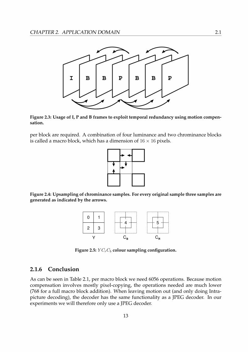
I B B P B B P
Figure 2.3: Usage of I, P and B frames to exploit temporal redundancy using motion compen-sation.
per block are required. A combination of four luminance and two chrominance blocksis called a macro block, which has a dimension of 16× 16 pixels.
Figure 2.4: Upsampling of chrominance samples. For every original sample three samples aregenerated as indicated by the arrows.
0 1
2 3
Y CRCB
54
Figure 2.5: Y CrCb colour sampling configuration.
2.1.6 Conclusion
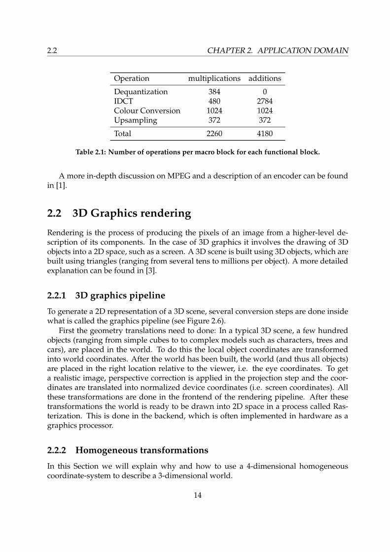
As can be seen in Table 2.1, per macro block we need 6056 operations. Because motioncompensation involves mostly pixel-copying, the operations needed are much lower(768 for a full macro block addition). When leaving motion out (and only doing Intra-picture decoding), the decoder has the same functionality as a JPEG decoder. In ourexperiments we will therefore only use a JPEG decoder.
13
2.2 CHAPTER 2. APPLICATION DOMAIN
Operation multiplications additions
Dequantization 384 0IDCT 480 2784Colour Conversion 1024 1024Upsampling 372 372
Total 2260 4180
Table 2.1: Number of operations per macro block for each functional block.
A more in-depth discussion on MPEG and a description of an encoder can be foundin [1].
2.2 3D Graphics rendering
Rendering is the process of producing the pixels of an image from a higher-level de-scription of its components. In the case of 3D graphics it involves the drawing of 3Dobjects into a 2D space, such as a screen. A 3D scene is built using 3D objects, which arebuilt using triangles (ranging from several tens to millions per object). A more detailedexplanation can be found in [3].
2.2.1 3D graphics pipeline
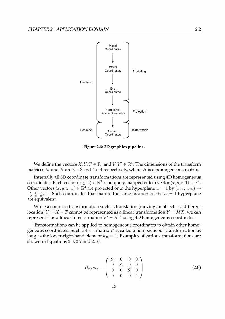
To generate a 2D representation of a 3D scene, several conversion steps are done insidewhat is called the graphics pipeline (see Figure 2.6).
First the geometry translations need to done: In a typical 3D scene, a few hundredobjects (ranging from simple cubes to to complex models such as characters, trees andcars), are placed in the world. To do this the local object coordinates are transformedinto world coordinates. After the world has been built, the world (and thus all objects)are placed in the right location relative to the viewer, i.e. the eye coordinates. To geta realistic image, perspective correction is applied in the projection step and the coor-dinates are translated into normalized device coordinates (i.e. screen coordinates). Allthese transformations are done in the frontend of the rendering pipeline. After thesetransformations the world is ready to be drawn into 2D space in a process called Ras-terization. This is done in the backend, which is often implemented in hardware as agraphics processor.
2.2.2 Homogeneous transformations
In this Section we will explain why and how to use a 4-dimensional homogeneouscoordinate-system to describe a 3-dimensional world.
14
CHAPTER 2. APPLICATION DOMAIN 2.2
ModelCoordinates
WorldCoordinates
EyeCoordinates
NormalizedDevice Coorinates
ScreenCoordinates
Projection
Rasterization
Modelling
Frontend
Backend
Figure 2.6: 3D graphics pipeline.
We define the vectors X, Y, T ∈ R3 and V, V ′ ∈ R4. The dimensions of the transformmatrices M and H are 3× 3 and 4× 4 respectively, where H is a homogeneous matrix.
Internally all 3D coordinate transformations are represented using 4D homogeneouscoordinates. Each vector (x, y, z) ∈ R3 is uniquely mapped onto a vector (x, y, z, 1) ∈ R4.Other vectors (x, y, z, w) ∈ R4 are projected onto the hyperplane w = 1 by (x, y, z, w) →( x
w, y
w, z
w, 1). Such coordinates that map to the same location on the w = 1 hyperplane
are equivalent.
While a common transformation such as translation (moving an object to a differentlocation) Y = X + T cannot be represented as a linear transformation Y = MX , we canrepresent it as a linear transformation V ′ = HV using 4D homogeneous coordinates.
Transformations can be applied to homogeneous coordinates to obtain other homo-geneous coordinates. Such a 4× 4 matrix H is called a homogeneous transformation aslong as the lower-right-hand element h33 = 1. Examples of various transformations areshown in Equations 2.8, 2.9 and 2.10.
Hscaling =
Sx 0 0 00 Sy 0 00 0 Sz 00 0 0 1
(2.8)
15

2.2 CHAPTER 2. APPLICATION DOMAIN
Htranslation =
1 0 0 Tx
0 1 0 Ty
0 0 1 Tz
0 0 0 1
(2.9)
Hx−rotation =
1 0 0 00 cos α − sin α 00 sin α cos α 00 0 0 1
(2.10)
A homogeneous vertex V can be transformed into V ′ by multiplication with a trans-formation matrix, V ′ = HV . Multiple transformations can be combined into one trans-formation, e.g. Hcombined = Htranslation ·Hscaling. To transform a vertex using a 4×4 matrix16 multiplications and 12 additions are required. When we have a reasonable complexscene which consists of 105 vertices and a framerate of 50 frames per second, a singletransform per vertex requires 50∗105∗(16+12) = 140·106 operations per second. Becauseseveral homogeneous transformations can be combined to a single homogeneous trans-formation matrix, on average less operations are needed for processing 4 dimensionalcoordinates instead of 3 dimensional coordinates.
2.2.3 Conclusion
We present an overview of the 3D graphics pipeline and a more detailed explanationof the use of homogeneous 4 dimensional coordinates to represent 3 dimensional co-ordinates. On average, 4 dimensional transformations require less operations than 3dimensional because they can be multiple transformations can be combined into a sin-gle transformation.
16

Chapter 3
PS2 architecture description
In this chapter we give a detailed description of the PlayStation 2 architecture.The PlayStation 2 architecture consists of essentially three blocks: control, graphics
and I/O. Control and calculations are done in the Emotion Engine (EE), graphics ren-dering is done in the Graphics Synthesizer (GS) and I/O is done in the IO processor(IOP).
EmotionEngine
GraphicsSynthesizerRDRAM
IOPSoundProcessor
IDE
USB
IEEE1394
Figure 3.1: PlayStation 2 block diagram.
In the following sections we will discuss the details of the Emotion Engine (Sec-tion 3.1), the Graphics Synthesizer (Section 3.2) and the IO processor in Section 3.3. Inthe final section we discuss the software and tools that have been used to develop andmap software on the PlayStation 2.
3.1 R5900 Emotion Engine CPU core
In this section, we highlight some of the interesting aspects of the PlayStation 2 architec-ture. A more detailed description can be found in the manuals provided by Sony [10].
17

3.1 CHAPTER 3. PS2 ARCHITECTURE DESCRIPTION
GS
GIF
VU Regs
VUMEM
microMEM
VIF
FMAC
DIV
VU1VU0MIPS CORE
VU Regs
microMEM
VIF
VUMEM
MMU48-
TLBs
SPR16 KB
D$8 KB
I$16 KB
UCABWBB
BIU
FMAC
MM/ALU0MM/ALU1
cop2
128
cop1
32
32x800MhzRDRAM
32SBUS/IOP
SIFIPU DRAMC
DMAC
128
INTC
Timer
INT1/cop0
INT0
FMACDIV
DIV
FPU
VSync/HSync
FIFO(Numbers show sizes in qwords.)
64
8 8 8
8 16
16
Figure 3.2: Emotion Engine block diagram.
3.1.1 MIPS core
The core CPU of the Emotion Engine (EE) (see Figure 3.2) is a MIPS III (partly MIPSIV) core running at 300MHz. It supports 2-way superscalar operation, allowing 2 in-structions to be executed in parallel every cycle. It has support for non-blocking loadinstructions and supports 128 bit SIMD multimedia instructions. The 32 general pur-pose registers are 128-bit wide, although the non-multimedia instruction only use thelower 64 bits.
The multimedia instructions operate on packed integer data in 128 bit registers. Theinstructions fall into two categories:
• applying the same operation, such as additions, multiplications, shifts on thepacked values using a single instruction,
• rearranging and conversion operations, such as converting 16 bit integers to 8 bitvalues or interleaving of values stored in two registers.
The CPU has an instruction cache (I-Cache) and a data cache (D-Cache). The data
18
CHAPTER 3. PS2 ARCHITECTURE DESCRIPTION 3.1
cache has the ability to load a necessary word from a cache line first (sub-block ordering)and to permit a hazard-free cache-line hit while a previous load is still in process (hit-under-miss). Since hit-under-miss effect is similar to the prefetch (PREF) instruction, itis effective when the address to be accessed is known in advance. Both caches are 2-wayassociative. The output from the cache is also buffered in the Write Back Buffer (WBB).The WBB is a FIFO of 8 qwords. Write requests are stored here, and then written tomemory according to the state of the main
Besides 16kB instruction cache and 8kB data cache, there is a 16kB scratchpad (SPR).There are two coprocessors available to the MIPS, a normal FPU which operates on32-bit floats, and a Vector Processing Unit (VU0).
3.1.2 Floating Point Unit
The Floating Point Unit (FPU) is a high performance single precision (see Subsection 3.1.4for IEEE compliance) floating point unit operating at 300MHzwith a throughput of 1operation per cycle for most operations, such as multiply and add. It contains a 1 cyclethroughput multiply-add operation and support for division. A total of 32 registers,each 32-bit in size, are available, giving a lot of programming flexibility. The FPU isconnected to the MIPS as coprocessor cop1.
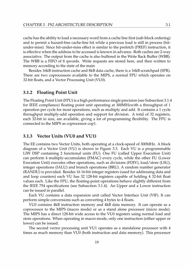
3.1.3 Vector Units (VU0 and VU1)
The EE contains two Vector Units, both operating at a clock-speed of 300MHz. A blockdiagram of a Vector Unit (VU) is shown in Figure 3.3. Each VU is a programmableLIW DSP containing 2 functional units (FU). One FU (called Upper Execution Unit)can perform 4 multiply-accumulates (FMAC) every cycle, while the other FU (LowerExecution Unit) executes other operations, such as divisions (FDIV), load/store (LSU),integer operations (IALU) and branch operations (BRU). A random number generator(RANDU) is provided. Besides 16 16-bit integer registers (used for addressing data andand loop counters) each VU has 32 128-bit registers capable of holding 4 32-bit floatvalues each. Like the FPU, the floating-point operations behave slightly different fromthe IEEE 754 specifications (see Subsection 3.1.4). An Upper and a Lower instructioncan be issued in parallel.
Each VU contains a data expansion unit called Vector Interface Unit (VIF). It canperform simple conversions such as converting 4 bytes to 4 floats.
VU0 contains 4kB instruction memory and 4kB data memory. It can operate as acoprocessor to the MIPS (macro mode) or as a stand alone processor (micro mode).The MIPS has a direct 128-bit wide access to the VU0 registers using normal load andstore operations. When operating in macro-mode, only one instruction (either upper orlower) can be issued.
The second vector processing unit VU1 operates as a standalone processor with 4times as much memory than VU0 (both instruction and data memory). This processor
19

3.1 CHAPTER 3. PS2 ARCHITECTURE DESCRIPTION
Micro Mem4KByte or 16KByte
Upper Instruction Lower Instruction
63 064
32 32
bold line : 128 bit
Micro instruction fetch unit
FMA
Cw
FMA
Cz
FMA
Cy
FMA
Cx
Upper Execution UnitR
AN
DU
/etc
LSU
IAL
U
EFU
Lower Execution UnitfloatingregistersVF00-VF31
(COP2 data registers)
127 0
BR
U
VU Mem4KByte or 16KByte
integerregistersVI00` VI15
16
16
16
QMTC2/ LQC2
QMFC2/ SQC2
CTC2
32
CFC2
32
specialregistersVI16` VI31
COP2control
registers
External Units
Vector Unit :VU
Vector Processing Unit:VPU
FDIV
VIF
Figure 3.3: Vector Unit block diagram.
has support for trigonometric and exponential functions in the Elementary FunctionUnit (EFU). To relieve the main bus (Subsection 3.1.7) VU1 can directly access data inthe VU0 data memory.
3.1.4 Differences from IEEE 754.
The floating-point operations in both the FPU and the VUs are not fully IEEE 754 [4]compliant. Only single-precision floating-point values are supported. There can berounding errors leading to a wrong value in the least significant bit (LSB). These smallrounding errors are the same for the FPU and the VUs. Whenever an exception occurs,such as under- or overflow or a division by zero, the processing is not interrupted, buta flag is set. If desired, a program can use a flag check after the calculation to check ifsomething abnormal did occur. In case of underflow, overflow, or a division by zero,results are saturated to the lowest or highest supported value. There is no support fornon-values such as not-a-number and infinity. The rationale behind this behaviour isthat a small error in the display is less of a problem than a part of a frame not beingrendered at all because of exception handling.
20
CHAPTER 3. PS2 ARCHITECTURE DESCRIPTION 3.1
3.1.5 IPU
To accelerate on the fly texture and video decoding, an Image Processing Unit (IPU)provides hardware accelerated block-level MPEG-2 decoding (entropy decoding, IDCTtransform and colour space conversion). If motion compensation has to be performed,as is the case in the MPEG-2 video, this has to be done on the MIPS.
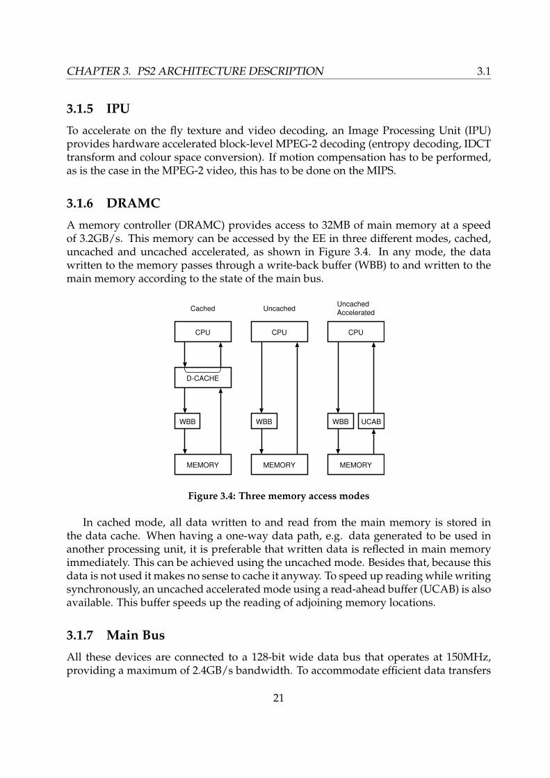
3.1.6 DRAMC
A memory controller (DRAMC) provides access to 32MB of main memory at a speedof 3.2GB/s. This memory can be accessed by the EE in three different modes, cached,uncached and uncached accelerated, as shown in Figure 3.4. In any mode, the datawritten to the memory passes through a write-back buffer (WBB) to and written to themain memory according to the state of the main bus.
WBB
CPU
MEMORY
D-CACHE
Cached
WBB
CPU
MEMORY
UncachedUncachedAccelerated
WBB UCAB
CPU
MEMORY
Figure 3.4: Three memory access modes
In cached mode, all data written to and read from the main memory is stored inthe data cache. When having a one-way data path, e.g. data generated to be used inanother processing unit, it is preferable that written data is reflected in main memoryimmediately. This can be achieved using the uncached mode. Besides that, because thisdata is not used it makes no sense to cache it anyway. To speed up reading while writingsynchronously, an uncached accelerated mode using a read-ahead buffer (UCAB) is alsoavailable. This buffer speeds up the reading of adjoining memory locations.
3.1.7 Main Bus
All these devices are connected to a 128-bit wide data bus that operates at 150MHz,providing a maximum of 2.4GB/s bandwidth. To accommodate efficient data transfers
21

3.2 CHAPTER 3. PS2 ARCHITECTURE DESCRIPTION
there is a 10 channel DMA controller to move data around between these devices, thescratch pad an the main memory. The different devices, such as the vector units, butalso the scratch pad are addressed as a source or destination using a dedicated channel.
3.1.8 Graphics Interface
The Emotion Engine is connected to the Graphics Synthesizer (see Section 3.2) using a64-bit wide bus at 150MHzgiving a transfer rate of 1.2GB/s. Data can be sent throughthe Graphics Interface (GIF) by VU1 or via the main bus. When data is sent from VU1to the GS, the main bus can be used in parallel for data transfers between other devices.
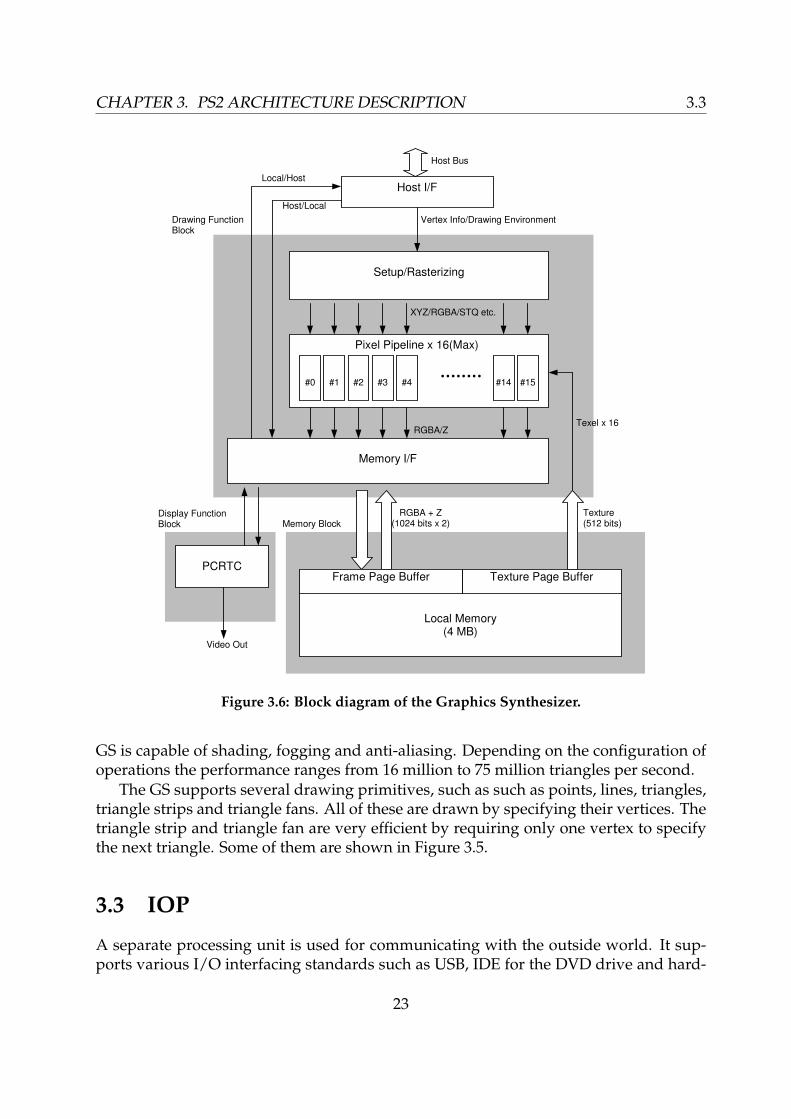
3.2 Graphics Synthesizer
The Graphics Synthesizer (GS) is the graphics processor of the PlayStation 2. It is re-sponsible for rendering all the graphics primitives, such as triangles, to the screen. TheGS runs at a clock speed of 150MHz.
1
2
3
4
5
6
(a) Lines
1
2
3
4
5
6
(b) Triangles
1
2
3
4
5
6
7
(c) Triangle strip
1
2
34
5
6
(d) Triangle fan
Figure 3.5: Several drawing primitives support by the GS
The chip contains 4MB of DRAM as a local memory to save pixel information (framebuffer and Z-buffer) generated by the drawing functions and texture information. Be-cause the memory is located inside the chip, it has a very high bandwidth to the mem-ory. The frame buffer is accessed through a 1024 bit port for reading and another 1024 bitport for writing. The textures are accessed through a separate 512 bit wide access port.This leads to a maximum frame buffer bandwidth of 38.4GB/s and a texture bandwidthof 9.6GB/s.
When rasterizing the 3D scene to the screen, the GS processes 16 pixels per cycle.When applying texture mapping, an additional multiplication is required for everypixel, resulting in a throughput of 8 pixels per cycle. Besides texture mapping, the
22
CHAPTER 3. PS2 ARCHITECTURE DESCRIPTION 3.3
Host I/F
Memory I/F
XYZ/RGBA/STQ etc.
Local Memory(4 MB)
Texture Page Buffer
RGBA + Z(1024 bits x 2)
PCRTC
Video Out
Host Bus
Local/Host
Vertex Info/Drawing EnvironmentDrawing FunctionBlock
Memory BlockDisplay FunctionBlock
Texture(512 bits)
Host/Local
Pixel Pipeline x 16(Max)
#0
Setup/Rasterizing
#1 #2 #3 #4 #14 #15
RGBA/Z
Frame Page Buffer
Texel x 16
Figure 3.6: Block diagram of the Graphics Synthesizer.
GS is capable of shading, fogging and anti-aliasing. Depending on the configuration ofoperations the performance ranges from 16 million to 75 million triangles per second.
The GS supports several drawing primitives, such as such as points, lines, triangles,triangle strips and triangle fans. All of these are drawn by specifying their vertices. Thetriangle strip and triangle fan are very efficient by requiring only one vertex to specifythe next triangle. Some of them are shown in Figure 3.5.
3.3 IOP
A separate processing unit is used for communicating with the outside world. It sup-ports various I/O interfacing standards such as USB, IDE for the DVD drive and hard-
23
3.4 CHAPTER 3. PS2 ARCHITECTURE DESCRIPTION
disk and IEEE1394 (Firewire). Access to the sound processor is also handled throughthis I/O processor. Exact details about both the I/O processor and the sound processorare only disclosed to Sony licensed developers, but are available through Linux kernelcalls, as discussed in the next section.
PlayStation 1 legacy games can be run on a MIPS R3000 included in the I/O pro-cessor, which operates at 34MHz. This processor cannot be accessed by PlayStation 2software. It is probably being used for (most of) the PS2 I/O operations.
3.4 Software and tools
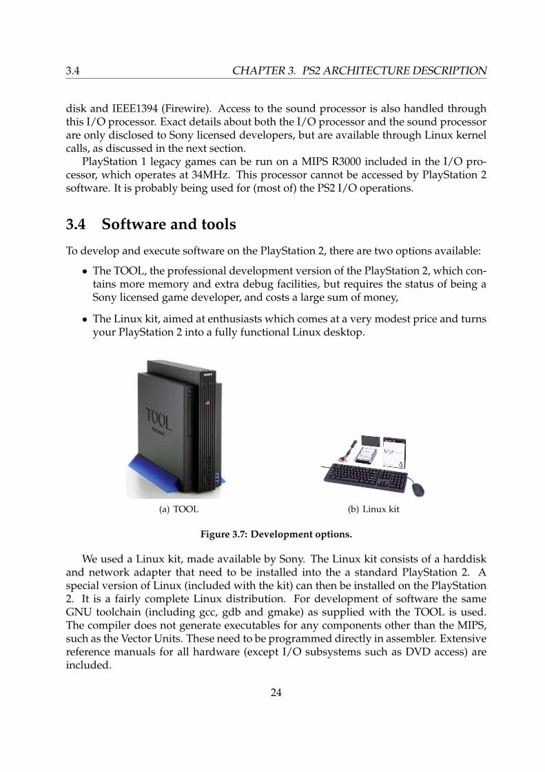
To develop and execute software on the PlayStation 2, there are two options available:
• The TOOL, the professional development version of the PlayStation 2, which con-tains more memory and extra debug facilities, but requires the status of being aSony licensed game developer, and costs a large sum of money,
• The Linux kit, aimed at enthusiasts which comes at a very modest price and turnsyour PlayStation 2 into a fully functional Linux desktop.
(a) TOOL (b) Linux kit
Figure 3.7: Development options.
We used a Linux kit, made available by Sony. The Linux kit consists of a harddiskand network adapter that need to be installed into the a standard PlayStation 2. Aspecial version of Linux (included with the kit) can then be installed on the PlayStation2. It is a fairly complete Linux distribution. For development of software the sameGNU toolchain (including gcc, gdb and gmake) as supplied with the TOOL is used.The compiler does not generate executables for any components other than the MIPS,such as the Vector Units. These need to be programmed directly in assembler. Extensivereference manuals for all hardware (except I/O subsystems such as DVD access) areincluded.
24
Chapter 4
Parallelism in micro-architectures
In this Chapter we describe different techniques to achieve parallelism in architecturesto improve performance of processors. We compare several processors with the Emo-tion Engine.
Credits: Most of Section 4.1 has been taken with kind permission from ”Trends inprogrammable instruction-set processor architectures” by H. Corporaal.
4.1 Architecture design space
In order to achieve the performance of a processor, it takes more then just increasing theclock frequency. The vast majority of processors applies one instruction at a time to asingle data stream. This technique is called, Single Instruction Single Data (SISD). Whenapplying the same instruction on multiple data streams is a popular method to increaseperformance. This technique is called Single Instruction Multiple Data (SIMD). Havingmultiple processors operate in parallel is even more common, as this parallelism is themost easy one to program. This is called Multiple Instruction Multiple Data (MIMD).There also exists Multiple Instruction Single Data (MISD), but this architecture is onlyuseful in very specific cases, and therefor not so common.
Each architecture can be specified as a 4-tuple (I, O,D, S), where I is the issue rate(instructions per cycle), O the number of (basic monadic or dyadic) operations specifiedper instruction, D the number of operands or operand pairs to which the operation isapplied, and S is the superpipelining degree. The latter is introduced by Jouppi [6], anddefined as
S(architecture) =∑
∀Op∈I set
f(Op)× lt(Op) (4.1)
where f(Op) is the relative frequency with which operation Op occurs in a representa-tive mix of applications, and lt(Op) is the latency of operation Op; lt(Op) indicates theminimal number of cycles after which operations, dependent on Op, have to be sched-uled in order not to cause pipeline stalls (in case the architecture supports dependence
25
4.2 CHAPTER 4. PARALLELISM IN MICRO-ARCHITECTURES
locking), or cause semantic incorrect results (in case the architecture does not lock ondependencies). lt is related to the number of delay slots d of an operation by:
lt(Op) = 1 + d(Op) (4.2)
For some architectures no clear numbers on the superpipelining could be found, weestimated these as being equal or close to 1.
Instructions/cycle ’I’
Operations/instruction ’O’
Data/operation ’D’
Vector Unit
MIPS Pentium4
RISC
TriMedia
Graphics Synthesizer
Imagine
FPU
Superpipelining degree ’S’
CISC 2 3
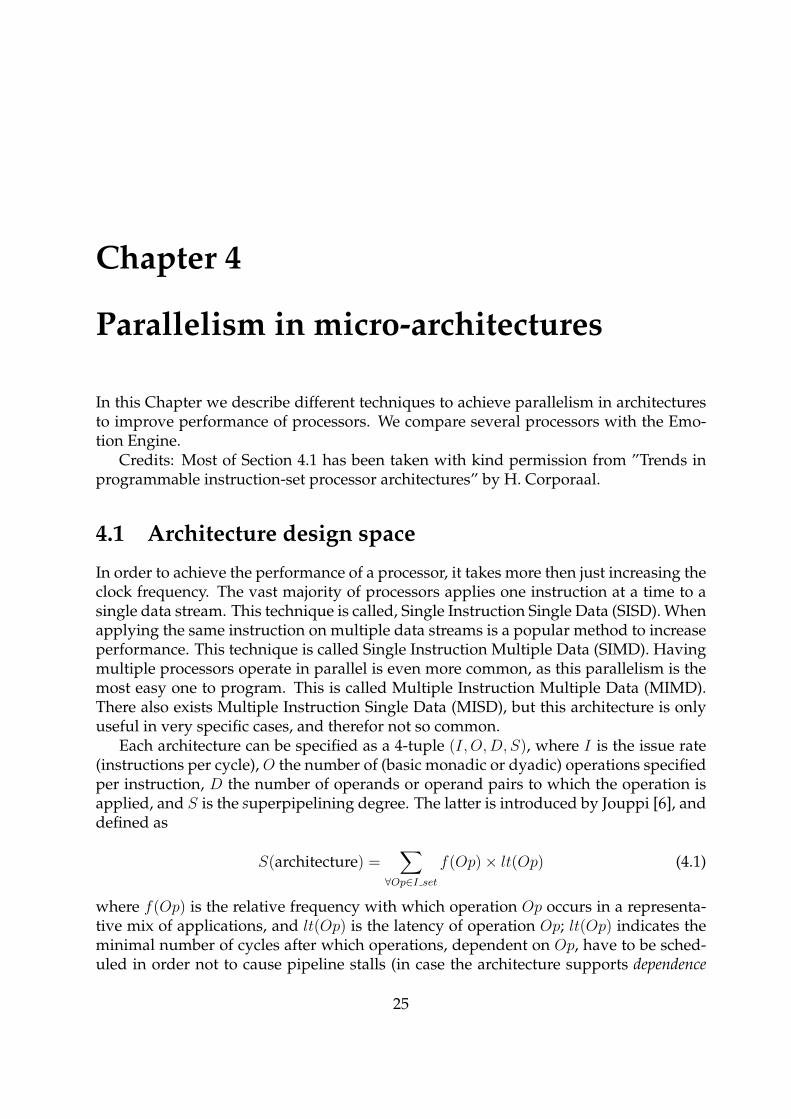
Figure 4.1: Four dimensional representation of the architecture design space.
Delay slots are invisible at the architectural level if dependence locking is used; inthat case filling them with independent operations is semantically not required. How-ever, filling them results in higher resource utilization and therefore better performance;this is part of the compiler’s job. The latency of non-pipelined operations is defined asone; S(CISC) is therefore one. The superpipelining degree indicates how many delayslots have to be filled (on average) in order to keep the processor busy.
RISC architectures are very close to the center (1,1,1,1) of the architectural designspace. RISCs have the potential of issuing one instruction per cycle (I = 1), where eachinstruction specifies one operation (O = 1), each operation applies to a single or singlepair of operands (D = 1), and the superpipelining degree is slightly larger than one(S ≈ 1).
26

CHAPTER 4. PARALLELISM IN MICRO-ARCHITECTURES 4.2
4.2 Examples
In this section we will describe some different architectures and how they achieve thelevel of parallelism they provide.
Typical values of (I, O,D, S) for the to be discussed architectures and several proces-sors described below are found in Table 4.1. K indicates the number of FUs or processornodes available. This table also indicates the amount of parallelism Mpar offered by thearchitecture; this number corresponds to the average number of operations in progress,at least when the hardware is kept busy, and is defined by:
Mpar = I ×O ×D × S (4.3)
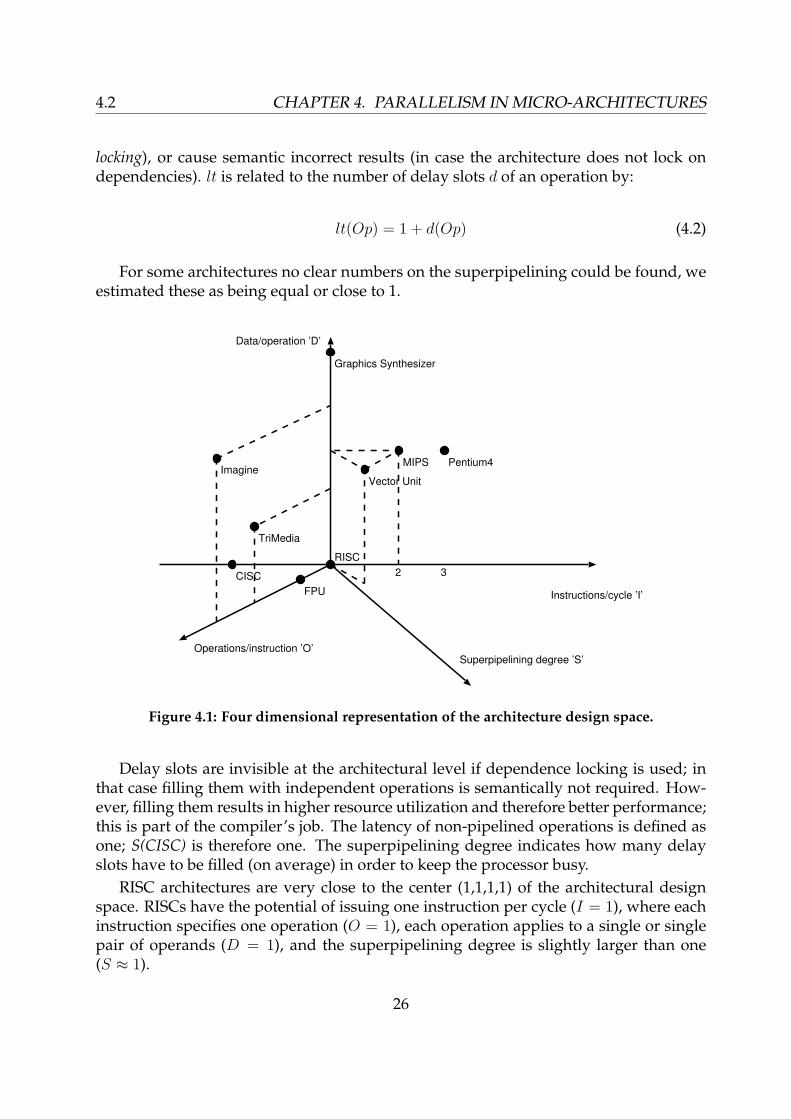
When taking the Emotion Engine and Graphics Synthesizer from the PlayStation 2and analyze them for the level of parallelism present, we get the values as presented inTable 4.2. When adding the values, we get a total level of 56 for parallelism, which isquite impressive. Because it is impossible to issue 2 instructions in the MIPS and one inthe FPU at the same time, the FPU line is left out from the totals.
4.2.1 CISC
A Complex Instruction Set Computer (CISC) is a microprocessor instruction set archi-tecture (ISA) in which each instruction can indicate several low-level operations, suchas a load or store from memory, and an arithmetic operation, all in a single instruction.The Intel 8086 is a CISC processor. While the instruction set was rich, the instructionsdiffered strongly in size, the number and type of operands.
ADD CX, DX ; Add contents of register DX to register CXADD AX, [VARIABLE] ; Add value pointed to by VARIABLE
; to register AX
4.2.2 RISC
The Reduced Instruction Set Computing (RISC) evolved from the CISC. RISC proces-sors have a much smaller and more simple (reduced) instruction set with a very limitednumber of addressing modes. With most instructions having the same size and per-forming more or less the same amount of work, they fit well in a simple pipeliningscheme. An example of a RISC processor is a MIPS, which has a 5 stage pipeline.
4.2.3 Pentium 4
The Pentium 4 can be categorized as a modern ”CISC” processor. It supports all the in-structions from its predecessors in the x86 architecture, translating these into microcodethat much more resembles RISC instructions that are executed internally. The P4 has a
27

4.3 CHAPTER 4. PARALLELISM IN MICRO-ARCHITECTURES
very deep pipeline of more than 20 (shorter) stages. While instructions have a higherlatency, because they have to go through more stages, the clockspeed can be increased.Because the average number of instructions per cycle remains the same, the actual per-formance increases along with the clockspeed.
4.2.4 TriMedia
The Trimedia [9] is a multimedia processor for high-performance multimedia applica-tions that deal with high-quality video and audio. The Trimedia core is a powerful32-bit DSPCPU. It implements a 32-bit linear address space and has 128, fully general-purpose 32-bit registers. The registers are not separated into banks. While this offersfull flexibility for register usage, any operation can use any register for any operand, thecomplexity of such a large register file has a negative impact on the cycle time.
The core uses a VLIW instruction-set architecture and is fully general purpose. Upto five operations can be issued per cycle. These operations can target any five of the 27functional units in the DSPCPU, including integer and floating-point arithmetic unitsand data-parallel multimedia operation units.
4.2.5 Imagine Stream Architecture
The Imagine Stream Architecture is a novel architecture that executes stream-based pro-grams. It provides high performance with 48 floating-point arithmetic units and a area-and power-efficient register organization. A streaming memory system loads and storesstreams from memory. A stream register file provides a large amount of on-chip inter-mediate storage for streams. Eight VLIW arithmetic clusters perform SIMD operationson streams during kernel execution. That is, the clusters can only perform the same in-struction in parallel, so one could call it an SIMD of VLIW clusters. Kernel execution issequenced by a micro-controller. A network interface is used to support multi-Imaginesystems and I/O transfers. Finally, a stream controller manages the operation of all ofthese units.
Architecture K I O D S Mpar
CISC 1 0.2 1.2 1.1 1 0.26RISC 1 1 1 1 1.2 1.2Pentium 4 10 3 1 4 > 1 12TriMedia 27 1 5 4 > 1 20Imagine 48 1 6 8 > 1 48
Table 4.1: Typical values of K, the number of FUs or processor nodes, and (I,O,D, S) fordifferent architectures.
28
CHAPTER 4. PARALLELISM IN MICRO-ARCHITECTURES 4.3
PlayStation 2 K I O D S Mpar
MIPS 1 2 1 4 > 1 8FPU 1 1 2 1 > 1 2Vector Unit (2) 2 2 2 4 > 1 16Graphics Synthesizer 1 1 1 16 > 1 16
Total 7 7 6 28 1 56
Table 4.2: PlayStation 2 values of K, the number of FUs or processor nodes, and (I,O,D, S).
4.3 Conclusion
In this chapter we have discussed several methods to achieve parallelism in architec-tures and illustrated these techniques with various existing processors. When lookingat the architecture of the PlayStation, most of the processing power of this architecturecomes from the high level of parallelism.
29

4.3 CHAPTER 4. PARALLELISM IN MICRO-ARCHITECTURES
30
Chapter 5
Mappings, experiments, results
In this chapter we investigate the actual performance that can be expected from thePlayStation 2. We will use two applications as a test case. The first is a JPEG decoder,because block based image-decoding is a fundamental part of most used image andvideo decoding and multimedia applications, like MPEG-1, 2 and 4, but also h.261 –h.264 and Windows Media Video.
Secondly we use a typical 3D rendering kernel for comparison. Since the PlayStation2 was designed with a strong focus on 3D graphics and games, we expect to see a topperformance here.
In Section 5.1 we introduce the test applications we have used in our experiments.We discuss the experiments and preset the results in Section 5.2. We draw conclusionsbased on these results in Section 5.3.
5.1 Test applications
In Sections 5.1.1 and 5.1.2 we introduce the application we have used in our experi-ments.
5.1.1 JPEG overview
A JPEG [8] bit-stream consists of general image information, table specifications and theactual compressed image data. The general information describes the information suchas the dimensions of the image and the colour space, e.g. Y, YCrCb, CMYK. The tablesspecify the Huffman codes used for the entropy coding and the quantization levels. Theremaining part consists of the compressed image data. The image is divided in blocksof 8 by 8 pixels. Most JPEGs have their colour information stored at half the resolutionof luminance (black and white) information, so for every 4 luminance blocks there are2 colour blocks. These 6 blocks together form a Macro block (MB) with a resolution of16× 16.
31

5.1 CHAPTER 5. MAPPINGS, EXPERIMENTS, RESULTS
DMX VLD IQ
CCV IDCT IZS
JPEG stream
image data
Figure 5.1: Block diagram of a JPEG decoder.
Figure 5.1 shows a block diagram of a JPEG decoder. The input of a JPEG decoder isa bit-stream connected to the demultiplexer block (DMX). The DMX block extracts thetables and general information necessary for decoding the image from the input stream.The remaining part is the actual compressed data, which is passed on to the variablelength decoder (VLD), which performs Huffman decoding followed by runlength de-coding to generate 64 image coefficients. These coefficients need to be dequantized bythe Inverse Quantizer (IQ) and reordered by the Inverse Zigzag Scan (IZS) to rebuildthe original block of 8 by 8 coefficients. This block is then transformed into the origi-nal colour information by applying a two dimensional Inverse Discrete Cosine Trans-form (IDCT). The resulting colour channels need to be transformed in the desired colourchannels, e.g. YCbCr → RGB conversion (CCV).
5.1.2 3D Perspective Matrix Transformation
To compute the view of a 3D model, the 3D world coordinates of the vertices in themodel must be converted to 2D screen coordinates, which determine which screen pixelrepresent each vertex. This conversion depends on the position and orientation of thevirtual camera in the 3D space and on the type of projection desired.
Figure 5.2 shows the basic configuration for a perspective viewing transformation.The 3-dimensional objects which are inside the view frustum are projected onto thedisplay window. This frustum, which is coloured grey in the figure, is the volumebounded by the near and far planes and the other for sides defined by (top, left) and(bottom, right). To transform the 3D coordinates Vobj = (vx, vy, vz) of these objects to 3Dcoordinates which are suitable for displaying on the screen, they must be transformedusing the perspective matrix Mperspective defined in Equation 5.1.
Mperspective =
2near
right−left0 right+left
right−left0
0 2neartop−bottom
top+bottomtop−bottom
0
0 0 −far+nearfar−near
−2·far·nearfar−near
0 0 −1 0
(5.1)
32

CHAPTER 5. MAPPINGS, EXPERIMENTS, RESULTS 5.2
(top, left)
(bottom, right)near
far
Camera
Display
Figure 5.2: Perspective viewing volume. The grey part is visible.
After the transform in Equation5.2 the coordinates need to be converted back tohomogeneous coordinates which can be used by the Graphics Synthesizer, shown inEquation 5.3. (
v′x v′y v′z v′w)T
= Mperspective ·(
vx vy vz 1)T (5.2)
Vgs =(
v′x
v′w
v′y
v′w
v′z
v′w
1)
(5.3)
5.2 Experiments
To achieve performance improvements, we focused on both computation and memoryoperations.
5.2.1 DTSE
For the memory improvements, we applied Data Transfer and Storage Exploration(DTSE), a technique that has been researched at IMEC. These techniques aim at improv-ing the locality and reducing the lifetime of temporary variables during processing. Ifmore operations are to be performed on a set of data, it is more efficient to apply allof them in one pass over the data instead of applying them all in separate passes. Thisreduces the need for temporary load/store operations, or at least improves cache usage.
Because the JPEG standard was written with limited memories in mind, there is littleto to gain in applying DTSE techniques. At most one macroblock totalling 384 bytes of
33
5.2 CHAPTER 5. MAPPINGS, EXPERIMENTS, RESULTS
Function Relative execution time
VLD 33%CCV 31%IDCT 29%
Table 5.1: Profiling information for JPEG decoder..
active data needs to be in memory. In our 3D kernel long streams of coordinates getprocessed, where DTSE won’t be of any help also. While we cannot reduce the numberof load/store operations any further, we did investigate the possibilities of using thescratchpad memory instead of the main memory. However, explicitly moving data tothe scratchpad memory did not give any improvements. The cache controller performsvery good in prefetching consecutive data, and offers sophisticated methods of controlas described in Section 3.1.6 when necessary.
5.2.2 JPEG
For the JPEG decoder we started using the JPEG decoder software written by the Inde-pendent JPEG Group (IJG) [5]. It is a high quality widely available and used implemen-tation in C of the JPEG standard. As a reference for high performance, we use the ImageProcessing Unit. There are no specifications available on decoding speed, but since thisunit is used for playback of DVDs, it should at least be fast enough for decoding anMPEG-2 PAL Standard Definition stream. MPEG-2 block decoding differs from JPEGonly in using fixed Huffman tables for the Variable Length Decoding.
Because the JPEG decoder mostly works only at one block at a time, there is little togain from DTSE.
PAL Video has a resolution of 720×576 at 25 frames per second (fps), or 45×36 = 1620macroblocks at 25 fps gives a minimum throughput of 40500 macroblocks per secondfor the IPU.
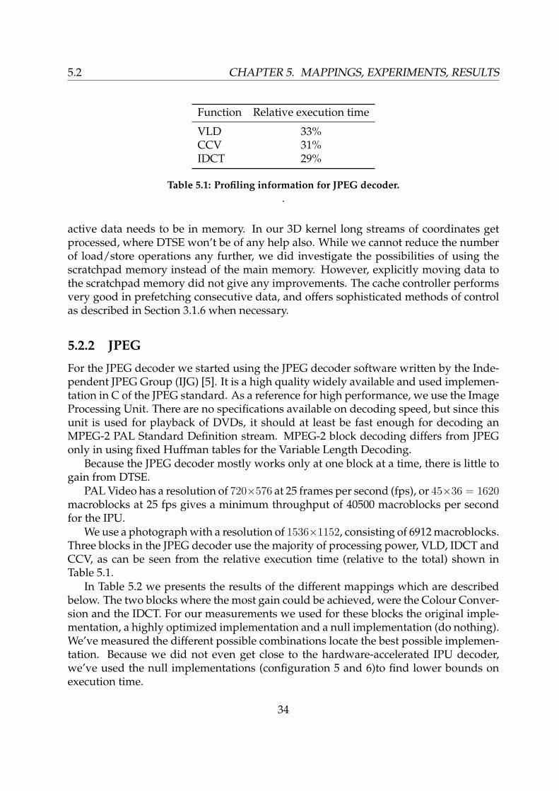
We use a photograph with a resolution of 1536×1152, consisting of 6912 macroblocks.Three blocks in the JPEG decoder use the majority of processing power, VLD, IDCT andCCV, as can be seen from the relative execution time (relative to the total) shown inTable 5.1.
In Table 5.2 we presents the results of the different mappings which are describedbelow. The two blocks where the most gain could be achieved, were the Colour Conver-sion and the IDCT. For our measurements we used for these blocks the original imple-mentation, a highly optimized implementation and a null implementation (do nothing).We’ve measured the different possible combinations locate the best possible implemen-tation. Because we did not even get close to the hardware-accelerated IPU decoder,we’ve used the null implementations (configuration 5 and 6)to find lower bounds onexecution time.
34
CHAPTER 5. MAPPINGS, EXPERIMENTS, RESULTS 5.2
Variable Length Decoding
In the VLD step codes varying in length from 1 to 16 bits are decoded to 8 bit values.Because most (> 95%) codes are less than 9 bits in size, they are looked up in a tableby using 8 bits of the bitstream as the index. If the code is longer than 8 bits, the next 8bits are used for a lookup in a second table. These tables contain (value, length) pairs,meaning the decoded value and the length of the code used. The bitstream is thenforwarded the number of bits specified by the length, which involves bitshifting thecurrent codeword and appending an also shifted part of the bitstream to it. For almost(except when the encoded value is exactly 8 bits long) every decoded value involves alot of sub-byte level aligned operations. Only the MIPS can perform these operationsreasonably well. The VLD inside the Image Processing Unit can unfortunately not beused for generic Huffman decoding, because the codetables cannot be changed. Theyare fixed in the MPEG-2 standard and the IPU strictly follows the standard strictly here,simplifying the hardware design.
Colour conversion
The CCV colour conversion is a more likely candidate for a different implementation.For every pixel the three colour components (R, G, B) are computed from the luminance(Y) and colour difference (Cr and Cb) components, using the following formulas:
R = Y + 1.40200 ∗ Cr (5.4)G = Y − 0.34414 ∗ Cb − 0.71414 ∗ Cr (5.5)B = Y + 1.77200 ∗ Cb (5.6)
For every pixel we need 4 multiplications and 4 additions/subtractions. Becauseboth the input as the output are integers, the multimedia SIMD instructions are theperfect candidate for implementing the colour conversion, enabling the processing of8 consecutive pixels at a time. This results in a speedup by a factor of 4 for the colourconversion, and an increase in the total decoding by a factor of 1.3.
When using a null conversion, which simply copies the components into the out-put buffer, the execution time actually gets worse. This is being caused by stallingload/store operations and ’dirty’ interleaving of data at offsets of 3 (every red compo-nent is separated by green and blue component and so on). In the standard conversionroutine the RGB values are written in one pass (without jumping through the array).The optimized version uses multimedia instructions for the interleaving and writes 8pixels at a time as 3 double words.
Inverse DCT
The IJG gives a choice between three implementations for the IDCT: one floating pointversion and two integer versions (a normal and a fast). The normal integer version is
35

5.2 CHAPTER 5. MAPPINGS, EXPERIMENTS, RESULTS
as specified by the standard, which performs equally fast as the floating point versionsince the instructions have the same throughput on the MIPS. The fast version sacrificessome accuracy for speed. We choose to move the floating point version to a vector unit.
The two dimensional IDCT can be separated into two one dimensional IDCT’s, firston each column and then on each row. The vertical IDCT can easily be transformed to avector unit. The 128 bit registers which can hold four 32 bit floats enable the processing4 floats in parallel instead of 1. A speedup by a factor of four is gained almost for free.
The horizontal IDCT is a completely different story however. The Vector Unit in-struction set has no support for data reorganization within a register, e.g. exchangingthe middle two floats inside a register (ABCD → ACBD). The only way to change aposition of a float is using so called broadcast instructions. These broadcast instructionscan assign the single float result of an operation to any 4 possible locations inside a reg-ister. Because the butterfly operations inside the IDCT algorithm require two positionchanges each, almost all possible speedup through parallelism in the implementation islost. Using the Vector Unit we can go from 16 1D IDCTs to 2 (four parallel) vertical and8 horizontal 1D IDCTs. The expected speedup is a factor of 16/(8 + 2) = 1.6 using oneVector Unit. When distributing the IDCT over both units, the speedup is dictated by theslowest of the two, being the horizontal IDCT resulting in a factor of 16/8 = 2.
The maximum gain we can expect is not performing an IDCT at all. When doing so,we achieve a throughput of 15710 macroblocks, or 0,44 seconds for decoding the image.
Using both Vector Units for the IDCT leads to an estimated execution time of 0, 44 +(0, 76 − 0, 44)/2 = 0, 60 seconds, or a throughput of 11529 macroblocks per second. Aperformance increase by a factor of 1.65 compared to the original C implementation, butthis still leaves us a factor 3.5 slower than the IPU.
Configuration IDCT CCV Execution time (s) MB/s compared to IPU
1 normal normal 0,97 7126 0.1762 fast normal 0,90 7680 0.1903 normal mmi 0,76 9095 0.2254 fast mmi 0,67 10316 0.2555 normal null 1,10 6284 0.1556 none mmi 0,44 15710 0.388
7 (estimated) VU0, VU1 mmi 0,60 11530 0.285
Table 5.2: Experimental results of different JPEG mappings.
5.2.3 Conclusions
Clear bottleneck is the Huffman decoding, which is quite complex for a processor due tothe many conditional branches and sub-byte level aligned operations. while being quiteeasy to implement efficiently in hardware. While the Vector Units excel at performing
36

CHAPTER 5. MAPPINGS, EXPERIMENTS, RESULTS 5.3
the same operation on multiple data (as being a true SIMD processor), the lack of fieldexchanging operations as found in the Multimedia Extensions in the MIPS reduces thereperformance to a normal FPU in such cases.
5.2.4 3D Perspective Matrix Transformation
The transformation requires 1 division, 7+3 = 10 multiplications (there are 7 coefficientsin the matrix, and 3 are needed for normalizing the x, y and z values of the calculatedresult) and 3 additions. When combining multiple transformation matrices, there num-ber of zeros in the matrix decreases, so in the worst case there need to be performed4 × 4 + 3 = 19 multiplications and 4 × 3 = 12 additions and 1 division. The additionscan be done using the multiply-add operation, so we can leave the additions out in bothcases. Since the Vector Unit can perform four multiplications and additions in parallel,we expect a performance increase by a factor of four.
On the FPU we implement both the minimal implementation, which computes ex-actly the calculations in Equations 5.2 and 5.3. The full implementations compute acomplete matrix multiplication, not exploiting the presence of zeros in the matrix. Wecount the number of cycles used in the innerloop, discarding initialization such as theloading of Mperspective into registers, since those values do not change during the render-ing of a frame.
Implementation # innerloop cycles speedup
FPU Full 29 1.0FPU Minimal 20 1.5VU Full 8 3.6
Table 5.3: Innerloop cyclecount of 3D Perspective Matrix Transformation
As we can see in Table 5.3, the full implementation on the Vector Unit is more thantwice as fast than the Minimal FPU implementation. When compared to the full imple-mentation we gain a speedup by a factor of 3.6! When doing typical 3D matrix manip-ulation it is in fact possible to achieve a speedup of almost 4 on the Vector Unit whencomparing to the MIPS.
5.3 Conclusion
When mapping a program on a specific architecture, an important factor in the perfor-mance one can achieve depends on how well the application ’fits’ on the architecture.The implementation of a 3D matrix transformation on the PlayStation 2 which targetsspecifically at 3D applications gives almost a factor 4 speed improvement when usingvector coprocessors.
37

5.3 CHAPTER 5. MAPPINGS, EXPERIMENTS, RESULTS
The mapping of the more generic JPEG decoding application, which still is close tothe domain of gaming and multimedia applications, gives a slightly less astonishingspeed improvement of 1.65.
Because the bus provides a very high bandwidth low latency, data transfers andload/store operations did not introduce any problems. An extra benefit is the excellentcache controller. Because both test applications require only a small amount of localdata and operate on larger consecutive amounts of data, the cache controller does aremarkable job. Because the cache was big enough, we did not benefit from using thescratchpad ram.
38
Chapter 6
PS2b: a better PS2
While the PlayStation 2 is a very successful platform with over 70 million units soldand still is the leading console even after 6 years of its introductions, it is not perfect. Inthis chapter, we present a better version of the PlayStation 2, or how the PlayStation 2really should have been. We will discuss both improvements in hardware (Section 6.1)and in software (Section 6.2). Based on these findings, we present our conclusions inSection 6.3.
6.1 Hardware
In our experiments, we came across some irritating (at least for us) limitations of thearchitecture.
1. The Vector Units could be used for many more functions than just vector process-ing when having some operations added. Most notably the ability to reorganizedata within registers. The multimedia instructions in the MIPS do support theseoperations, and are indeed very useful. They are quite common in most currentarchitectures, such as in the PowerPC Altivec and the Intel SSE.
2. The Image Processing Unit is very fast at what it is designed for, namely decodingMPEG-2 streams. It is however also very inflexible. The VLD Huffman decoderwould be very useful if the decoding tables could be defined in software.
3. While adding hardware accelerators, a cryptographic accelerator would come inhandy. Both for secure internet transactions, as online gaming is expected to fi-nally become big, and Digital Rights Management (DRM) protection for content1.
4. Typical vertex processing operations on the Vector Units can produce 15 to 20million vertices per second. This is far below the limit of 75 million the GraphicsSynthesizer can render, unless all the nice features such as shading, fogging and
1Some will argue this would be a reason to leave it out
39

6.2 CHAPTER 6. PS2B: A BETTER PS2
anti-aliasing are turned on simultaneously. Besides, we want to use the VUs alsofor other purposes, such as Artificial Intelligence (AI) processing and simulatingphysics. AI algorithms such as reinforcement learning are nothing more than largevector multiplications.
5. A larger memory inside a VU would be nice for this, but not essential. Becausethe memory inside the VU can be accessed by both the the VU and the DMAC atthe same time, one can set up the memory for double-buffer processing. That is,the VU operates on one part of the memory and the DMA reads/writes the otherpart. After the VU has finished processing both memory areas can be swapped.However when enlarging the memory, more registers are more than welcome.This way complex operations can be combined in larger loops, without the need ofloading the same coefficients every iteration again because of register starvation.
6. Even more important would be equal memory sizes for the vector units. Currently,every program that can be executed on VU0 can also be executed on VU1, theother way around is not always true. Not only does VU0 lack some instructionspresent in VU1 (although they are not that often required), more important is thedifference in memory size by a factor of four. Once a decision has been made tolocate a program on VU1, it is often impossible to move it to VU0.
7. When generating complex (i.e. high polygon count) scenes, all processing capa-bilities of the vector units are required to create the scene. As a result little AI andphysics processing can be done. As a solution to this situation more main memorycould be installed, so behaviour or scenes can be precalculated and loaded frommemory instead of being regenerated every time. A much more flexible solutionis of course to install more vector units. When using some of the options like shad-ing and anti-aliasing in the graphics synthesizer, two vector units will generallybe sufficient to generate complex scenes at full framerate (i.e. 50fps for a PAL ver-sion). On the other hand, one vector unit can be used for so capable of simulatingrelatively complex and realistic behaviour through AI processing, while the otherVU simulates object movements and behaviour through physics processing andcollision detection. Instead of having to choose between both situations, it wouldgenerally be nice to do all these operations in parallel and to be forced to makea trade-off. An additional two vector units (so a total of four) will be sufficientfor both realistic intelligence, object movements and pushing the graphics moreto the limit and actually achieving full framerate. Many games run only at halfthe framerate, so 25 fps for a PAL version. This results in visual artifacts such asmotion judder and less smooth animations [2].
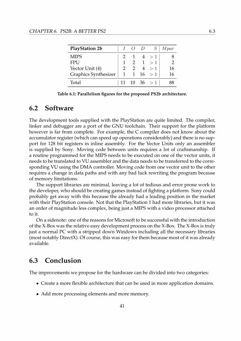
The resulting figures for parallelism achieved in the PS2b, are presented in Table 6.1.When adding up the numbers to calculate the total, again the FPU line is left out becausea maximum of two instructions can be issued every cycle when using the FPU andMIPS together. The total level of parallelism is 88, which is 1.57 times higher than theparallelism of the original PS2, which is 56.
40
CHAPTER 6. PS2B: A BETTER PS2 6.3
PlayStation 2b I O D S Mpar
MIPS 2 1 4 > 1 8FPU 1 2 1 > 1 2Vector Unit (4) 2 2 4 > 1 16Graphics Synthesizer 1 1 16 > 1 16
Total 11 10 36 > 1 88
Table 6.1: Parallelism figures for the proposed PS2b architecture.
6.2 Software
The development tools supplied with the PlayStation are quite limited. The compiler,linker and debugger are a port of the GNU toolchain. Their support for the platformhowever is far from complete. For example, the C compiler does not know about theaccumulator register (which can speed up operations considerably) and there is no sup-port for 128 bit registers in inline assembly. For the Vector Units only an assembleris supplied by Sony. Moving code between units requires a lot of craftsmanship. Ifa routine programmed for the MIPS needs to be executed on one of the vector units, itneeds to be translated to VU assembler and the data needs to be transferred to the corre-sponding VU using the DMA controller. Moving code from one vector unit to the otherrequires a change in data paths and with any bad luck rewriting the program becauseof memory limitations.
The support libraries are minimal, leaving a lot of tedious and error prone work tothe developer, who should be creating games instead of fighting a platform. Sony couldprobably get away with this because the already had a leading position in the marketwith their PlayStation console. Not that the PlayStation 1 had more libraries, but it wasan order of magnitude less complex, being just a MIPS with a video processor attachedto it.
On a sidenote: one of the reasons for Microsoft to be successful with the introductionof the X-Box was the relative easy development process on the X-Box. The X-Box is trulyjust a normal PC with a stripped down Windows including all the necessary libraries(most notably DirectX). Of course, this was easy for them because most of it was alreadyavailable.
6.3 Conclusion
The improvements we propose for the hardware can be divided into two categories:
• Create a more flexible architecture that can be used in more application domains.
• Add more processing elements and more memory.
41

6.3 CHAPTER 6. PS2B: A BETTER PS2
The first category requires relatively small modifications (e.g. addition of instruc-tions to the processing elements), but is only interesting if the architecture is to be de-ployed in different application domains than game processing. The second categorynot only increases the processing power and possibilities of the architecture, but also in-crease the costs a lot (mainly due to the chip size). Now smaller production techniquesare available, these additions (such as extra vector units) are feasible.
The main point about software is that there are no decent tools available to use thearchitecture to the max. While maybe not available at the time of introduction, moresophisticated development tools (such as a compiler for the vector units) should havebeen made available.
42
Chapter 7
PS3: overview of the Cell architecture
The successor of the PlayStation 2, labelled PlayStation 3, has a big hype around it’s newCell architecture. Most details about the Cell in this chapter are taken from the overviewpresented in [7]. We will first give an overview of the Cell architecture in Section 7.1. Wewill compare the Cell architecture in Section 7.2 with the improved PS2b we proposedin Chapter 6.
7.1 The Cell Processor
At the heart of the PlayStation 3 is a Cell processor, a cooperative design by IBM, Sonyand Toshiba. Besides the new PlayStation, the chip will also be used in upcomingToshiba television sets. The Cell will operate at a clockspeed of 4GHz, but can be usedat 3GHz using a lower voltage, which would reduce the power consumption consid-erably. The PlayStation 3 is expected to run at the lower 3GHz clockspeed. Figure 7.1shows a block diagram of the Cell architecture.
The Cell consists of three main units, supported by two Rambus interfaces. Thereis a single PowerPC core that acts as the main host processor, eight SIMD processors(SPU), and a highly programmable DMA controller (MFC).
7.1.1 Synergistic Processor Unit
The Cell processor contains eight Synergistic Processor Units (SPU). The SPU is thesuccessor of the VU in the PlayStation 2. Each SPU is a four-way SIMD unit optimizedfor single-precision floating point. It contains 128 128-bit wide registers, which reducesthe need for load store operations. The instruction set is a superset of the PlayStation 2Vector Unit instruction set including multiply-add, with a flavour of Altivec instructionsadded (as found in other PowerPC CPU’s, such as the Power G4). At a clockspeed of4GHz, the eight SPUs will be capable of a peak performance of 256MFlops.
The Local Storage (LS) SRAM memory has a size of 256kB, which is used for bothboth instructions and data. The LS memory is mapped in the global memory space,
43

7.1 CHAPTER 7. PS3: OVERVIEW OF THE CELL ARCHITECTURE
SPU
LS
SPU
LS
SPU
LS
SPU
LS
LS
SPU
LS
SPU
LS
SPU
LS
SPU
MFC
Dual XDR
IOC
RRAC I/O
PowerPC
L1
L2
EIB
Figure 7.1: Block diagram of the Cell processor.
however it is not cache coherent with respect to modifications made by the SPU to whichit belongs.
7.1.2 Memory Flow Controller
The Memory Flow Controller (MFC) is a highly programmable DMA controller. TheMFC is responsible for transferring data between main memory, the SPU local storages.For time-critical operations the MFC has the ability to transfer data from an SPU localstore directly into the L2 cache of the PowerPC. To keep the Cell processor running andthe SPU utilization high, the MFC supports 12 simultaneous transaction flows. Whentransferring data to an SPU, the MFC can instruct the SPU to begin processing instruc-tions after the transfer has finished.
The MFC supports DMA-list command schemes. The list of DMA commands isplaced in the local store and then processed asynchronously by the MFC.
7.1.3 Memory and I/O
The memory and I/O interfaces are based on Rambus technology. The I/O Controller(IOC), consists actually of two independent controllers for flexibility. The memory in-terface can support a bandwidth of 25.6GB/s. Two Cells can be connected using theRRAC connection.
44
CHAPTER 7. PS3: OVERVIEW OF THE CELL ARCHITECTURE 7.2
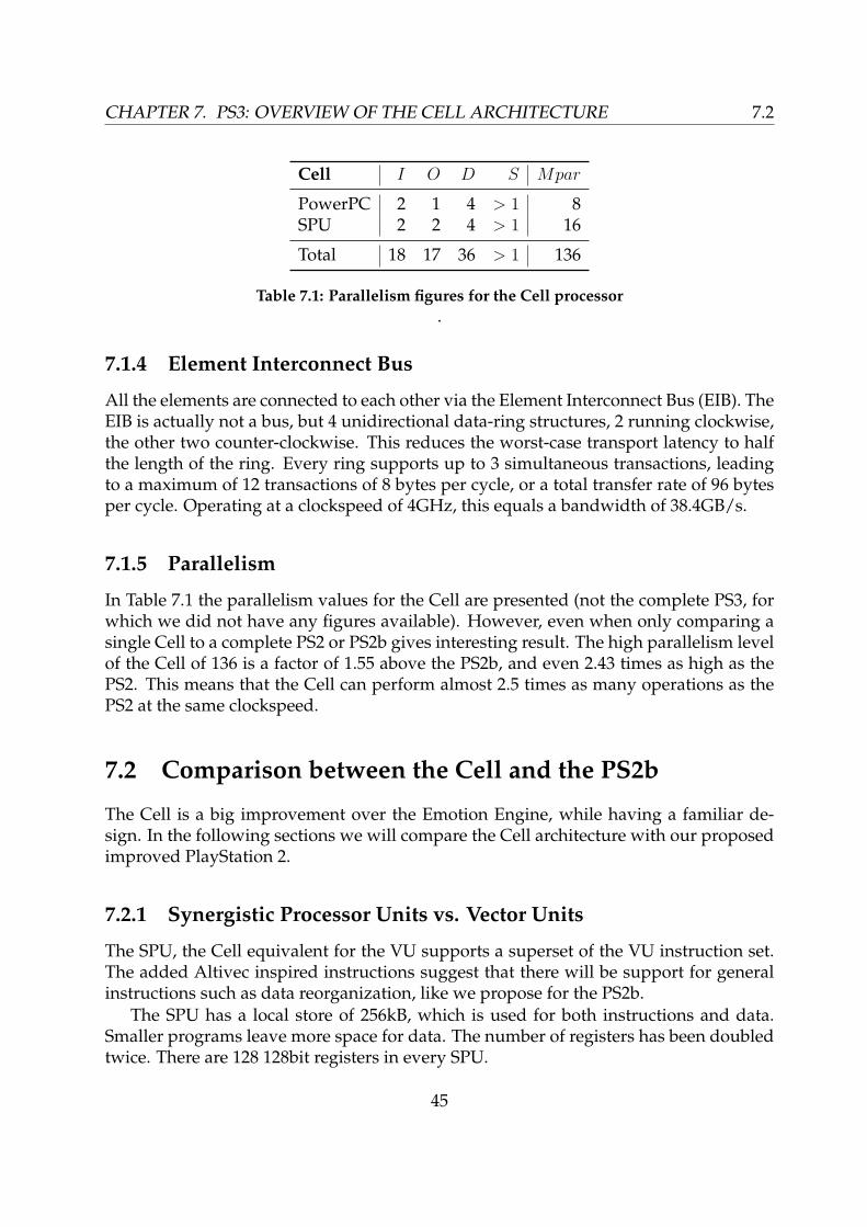
Cell I O D S Mpar
PowerPC 2 1 4 > 1 8SPU 2 2 4 > 1 16
Total 18 17 36 > 1 136
Table 7.1: Parallelism figures for the Cell processor.
7.1.4 Element Interconnect Bus
All the elements are connected to each other via the Element Interconnect Bus (EIB). TheEIB is actually not a bus, but 4 unidirectional data-ring structures, 2 running clockwise,the other two counter-clockwise. This reduces the worst-case transport latency to halfthe length of the ring. Every ring supports up to 3 simultaneous transactions, leadingto a maximum of 12 transactions of 8 bytes per cycle, or a total transfer rate of 96 bytesper cycle. Operating at a clockspeed of 4GHz, this equals a bandwidth of 38.4GB/s.
7.1.5 Parallelism
In Table 7.1 the parallelism values for the Cell are presented (not the complete PS3, forwhich we did not have any figures available). However, even when only comparing asingle Cell to a complete PS2 or PS2b gives interesting result. The high parallelism levelof the Cell of 136 is a factor of 1.55 above the PS2b, and even 2.43 times as high as thePS2. This means that the Cell can perform almost 2.5 times as many operations as thePS2 at the same clockspeed.
7.2 Comparison between the Cell and the PS2b
The Cell is a big improvement over the Emotion Engine, while having a familiar de-sign. In the following sections we will compare the Cell architecture with our proposedimproved PlayStation 2.
7.2.1 Synergistic Processor Units vs. Vector Units
The SPU, the Cell equivalent for the VU supports a superset of the VU instruction set.The added Altivec inspired instructions suggest that there will be support for generalinstructions such as data reorganization, like we propose for the PS2b.
The SPU has a local store of 256kB, which is used for both instructions and data.Smaller programs leave more space for data. The number of registers has been doubledtwice. There are 128 128bit registers in every SPU.
45
7.3 CHAPTER 7. PS3: OVERVIEW OF THE CELL ARCHITECTURE
While we suggest to have 4 Vector Units in the PS2b, there are 8 SPUs in the Cell.There are two possible reasons for this. With a more powerful graphics processor be-tween the Cell and the screen, it is likely to be beneficial to have more SPUs. Besidesthat, the SPUs can be regarded as flexible (fully programmable) accelerators, as we dis-cuss in Sections 7.2.2, 7.2.3.
7.2.2 Image Processing Unit
While being practical for decoding MPEG-2 streams but inflexible for almost everythingelse, the IPU is not found in the Cell. Maybe parts of it will reappear inside the graphicsprocessor (in PC’s it’s quite common to have IDCT and colour conversion been done bythe video processor), but on the other hand MPEG-2 decoding is no challenge at all forthe PowerPC.
7.2.3 Crypto accelerator
The generic Huffman accelerator we proposed didn’t find it’s way into the Cell, but thecryptographic accelerator did, sort of. SPUs can be fenced of from each other throughhardware protection features. A separated SPU can the safely be used for security pro-cessing operations.
7.2.4 Programming
The programming toolchain for the Cell is built on PowerPC Linux. There is also aC(++) compiler for the SPU. This will definitely ease the process of moving functionsaway from the PowerPC to one of the SPUs. If there are good support libraries availableis not clear yet, but the availability of a C compiler for the SPUs is a positive sign.
7.3 Conclusion
The Cell/PS3 has very impressive specifications, and most limitations we encounteredin the PS2 design have been removed in the PS3. Adding a high clockspeed (estimated4GHz), this will indeed be a very powerful platform. How well it will perform in thefield will depend a lot on the quality of the supplied development tools, as this plat-form takes complexities to yet another level where manual design becomes less andless viable.
46
Chapter 8
Conclusions and future work
8.1 Conclusions
The results presented in Chapter 5 show that we can achieve a higher decoding speedfor JPEG images. By using other instructions and using more processing units we’veincreased the processing speed by a factor of 1.6. This is however, still 3.5 times slowerthan the MPEG-2 decoding speed delivered by the Image Processing Unit. Main reasonsare the Huffman decoder that cannot be moved away from the MIPS and the lack of datareorganization functions in the Vector Units.
The mapping of a 3D Perspective Transform, gives a speed improvement of 3.6,which is close to our expected improvement by a factor of 4. Clearly, processing vectorand matrix multiplications at high speed is one of the key performance points of thePlayStation 2.
Not only are most of the improvements we suggest in Chapter 6 are actually presentin the Cell processor, that will be used inside the PlayStation 3. The Cell processor goesfurther than the PS2b with even more processing elements and an expected decent tool-chain.
8.2 Future work
While not all details of the Cell are yet revealed, the most interesting research topic isthe development of a programming paradigm to program the different units easy, evenwhen connecting more Cells together. Use of a library such as Yapi as being used forSpacecake comes to mind.
47

CHAPTER 8. CONCLUSIONS AND FUTURE WORK
48

Appendix A
Glossary
AI Artificial Intelligence.
DRM Digital Rights Management.
DTSE Data Transfer and Storage Exploration.
EE Emotion Engine. CPU of the PlayStation 2.
IJG Independent JPEG Group.
IPU EE image processor unit.
SIMD Single Instruction Multiple Data. Perform the same operation on a multiple ofsmall operands which are packed together into one register.
SPR ScratchPad Ram. Quick-access data memory built into the EE Core.
VPU Vector processing unit. EE contains 2 VPUs: VPU0 and VPU1.
VU VPU core operation unit.
VIF VPU data decompression unit.
49

APPENDIX A. GLOSSARY
50
Bibliography
[1] Vasudev Bhaskaran and Konstantinos Konstantinides. Image and video compressionstandards, algorithms and architectures. Kluwer Academic Publishers, 1997.
[2] Gerard de Haan. Video processing for multimedia systems. Eindhoven UniversityPress, 2000.
[3] David H. Eberly. 3D game engine design. Morgan Kaufmann, 2001.
[4] ANSI/IEEE 754-1985, Standard for Binary Floating-Point Arithmetic. IEEE, New York,NY, USA, August 1985.
[5] Independent jpeg groupd, http://www.ijg.org/.
[6] NP Jouppi and D.W Wall. Available instruction-level parallellism for superscalarand superpipelined machines. In Proceedings of the 3rd International Conference onArchitectural Support for Programming Languages and Operating Systems, April 1989.
[7] Kevin Krewell. Cell moves into the limelight. Microprocessor Report, Volume 19Archive 2, February 2005.
[8] William B. Pennebaker and Joan L. Mitchell. JPEG still image data compression stan-dard. Van Nostrand Reinhold, 1993.
[9] Gert Slavenburg. Trimedia TM1000 Data Book. Philips, 1998.
[10] Sony Computer Entertainment. EE User’s Manual, version 5.0 edition, 2001.
[11] Pavan Tumati. Sony playstation-2 vpu: A study on the feasibility of utilizing gam-ing vector hardware for scientific computing. Master’s thesis, University of Illinois,2003.
51