
Electrical #002-Cathodic Protection Rev 2
31
SENORO GAS DEVELOPMENT PROJECT CATHODIC PROTECTION SYSTEM February 17, 2011 Monthly Project Forum – Electrical Discipline
-
Upload
kurniadi-setyanto -
Category
Documents
-
view
226 -
download
0
Transcript of Electrical #002-Cathodic Protection Rev 2

7/27/2019 Electrical #002-Cathodic Protection Rev 2
http://slidepdf.com/reader/full/electrical-002-cathodic-protection-rev-2 1/31
SENORO GAS DEVELOPMENT PROJECTCATHODIC PROTECTION SYSTEM
February 17, 2011
Monthly Project Forum – Electrical Discipline

7/27/2019 Electrical #002-Cathodic Protection Rev 2
http://slidepdf.com/reader/full/electrical-002-cathodic-protection-rev-2 2/31
WHAT IS CATHODIC PROTECTION
INTRODUCTION OF CATHODIC PROTECTION
• Cathodic Protection is a technique to reduce the corrosion rate of ametal surface by making it the cathode of an electrochemical cell.(In this presentation, is limited to steel pipe installed underground)
• Two Kind of Cathodic Protection,- Sacrificial Anode
- Impress Current

7/27/2019 Electrical #002-Cathodic Protection Rev 2
http://slidepdf.com/reader/full/electrical-002-cathodic-protection-rev-2 3/31
Why Use Cathodic Protection?
INTRODUCTION OF CATHODIC PROTECTION
•
Cathodic Protection is presented to reduce corrosion rate in metalsurface especially that installed underground.• Cathodic Protection system is usually as secondary protection
against corrosion in metal surface installation. The primary protectionis coating system.
The reason that placed cathodic protection as secondary protectionsystem against corrosion is the coating of steel pipe is contain holiday(or insulation leakage), and using cathodic protection as primaryprotection is usually uneconomical, especially in tropical climate.

7/27/2019 Electrical #002-Cathodic Protection Rev 2
http://slidepdf.com/reader/full/electrical-002-cathodic-protection-rev-2 4/31
INTRODUCTION OF CATHODIC PROTECTION
7/27/2019 Electrical #002-Cathodic Protection Rev 2
http://slidepdf.com/reader/full/electrical-002-cathodic-protection-rev-2 5/31
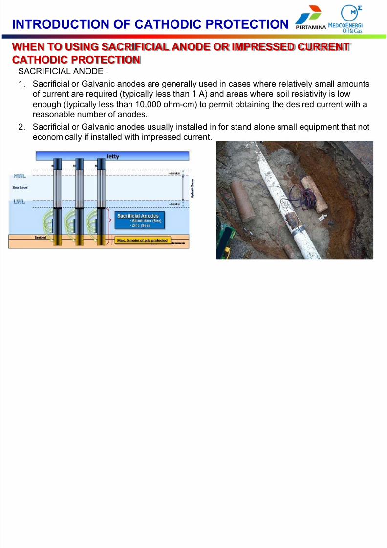
WHEN TO USING SACRIFICIAL ANODE OR IMPRESSED CURRENTCATHODIC PROTECTION
INTRODUCTION OF CATHODIC PROTECTION
SACRIFICIAL ANODE :1. Sacrificial or Galvanic anodes are generally used in cases where relatively small amounts
of current are required (typically less than 1 A) and areas where soil resistivity is lowenough (typically less than 10,000 ohm-cm) to permit obtaining the desired current with areasonable number of anodes.
2. Sacrificial or Galvanic anodes usually installed in for stand alone small equipment that noteconomically if installed with impressed current.

7/27/2019 Electrical #002-Cathodic Protection Rev 2
http://slidepdf.com/reader/full/electrical-002-cathodic-protection-rev-2 6/31
WHEN TO USING SACRIFICIAL ANODE OR IMPRESSED CURRENTCATHODIC PROTECTION
INTRODUCTION OF CATHODIC PROTECTION
IMPRESSED CURRENT:1. Impressed Current Cathodic Protection are generally used in cases where amounts of
current are big (typically more than 1 A).2. Economical and the applicability of impressed current cathodic protection installation shall
be considered.

7/27/2019 Electrical #002-Cathodic Protection Rev 2
http://slidepdf.com/reader/full/electrical-002-cathodic-protection-rev-2 7/31
A COMPARISON OF SACRIFICIAL ANODE AND IMPRESSED CURRENTSYSTEMS
INTRODUCTION OF CATHODIC PROTECTION
Sacrificial anodes1. Easy to install2. No Electricity Required3. Low of the risk of over protection
4. Little or No MaintenanceRequired
5. No operational Cost (OnlyRoutine Check)
6. Current Output is Limited7. Not Applicable when soil
resistivity is High
Impress Current1. Good for Big Structure Installation2. Applicable for all Soil resistivity
Condition
3. Current Protection is easy to control4. Initial Cost is Low5. Electricity dependent6. Operation Cost and Maintenance
Required7. Over Protection Risk

7/27/2019 Electrical #002-Cathodic Protection Rev 2
http://slidepdf.com/reader/full/electrical-002-cathodic-protection-rev-2 8/31
WHAT IS CORROSION
CORROSION
• Corrosion is degradation of a material through environmentalinteraction. This definition encompasses all materials, both naturallyoccurring and man-made and includes plastics, ceramics, andmetals.(PEABODY’S CONTROL OF PIPELINE CORROSION BOOK, Page 1)
•
In this presentation, we will focuses on the corrosion of metals, withemphasis on corrosion of steels installed underground.
7/27/2019 Electrical #002-Cathodic Protection Rev 2
http://slidepdf.com/reader/full/electrical-002-cathodic-protection-rev-2 9/31
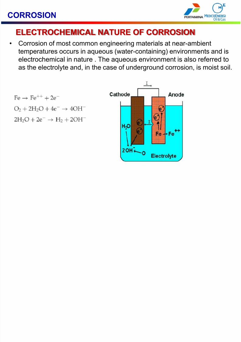
ELECTROCHEMICAL NATURE OF CORROSION
CORROSION
• Corrosion of most common engineering materials at near-ambienttemperatures occurs in aqueous (water-containing) environments and iselectrochemical in nature . The aqueous environment is also referred toas the electrolyte and, in the case of underground corrosion, is moist soil.

7/27/2019 Electrical #002-Cathodic Protection Rev 2
http://slidepdf.com/reader/full/electrical-002-cathodic-protection-rev-2 10/31
CORROSION
ATMOSPHERIC CORROSION •
Atmospheric corrosion can be defined as the corrosion of materialsexposed to the air and its pollutants, rather than immersed in a liquid .
Atmospheric corrosion can further be classified into dry, damp, and wetcategories. This chapter deals only with the damp, and wet cases,associated with corrosion in the presence of microscopic, "invisible"
electrolyte (or moisture) films and visible electrolyte layers on thesurface, respectively.

7/27/2019 Electrical #002-Cathodic Protection Rev 2
http://slidepdf.com/reader/full/electrical-002-cathodic-protection-rev-2 11/31
CORROSION
MICROBIOLOGICALLY INFLUENCED CORROSION • Microbiologically influenced corrosion (MIC) is corrosion resulting from
the presence and activities of microorganisms, including bacteria andfungi.
• Microbiological that cause corrosion in metal can be grouped into- Metal-Oxidizing Bacteria (MOB)- Sulfate-Reducing Bacteria (SRB)- Acid-Producing Bacteria (APB)- Metal-Reducing Bacteria (MRB)

7/27/2019 Electrical #002-Cathodic Protection Rev 2
http://slidepdf.com/reader/full/electrical-002-cathodic-protection-rev-2 12/31
PRINCIPE OF CATHODIC PROTECTION
• The Principe of Cathodic Protection is to make a protected metal (in thiscase is Steel Pipe) the cathode of an electrochemical cell.- Two way to make a protected metal as the cathode of electrochemical
cell:
1. Connected the negative of DCterminal power source and thepositive terminal of DC power isconnected to another metal(ground bed). This is animpressed current method
2. Connected to the metal thathave more negative potentialthan protected metal. This isSacrificial Anode method

7/27/2019 Electrical #002-Cathodic Protection Rev 2
http://slidepdf.com/reader/full/electrical-002-cathodic-protection-rev-2 13/31
PRINCIPE OF CATHODIC PROTECTION
Table of Galvanic Potential of Metal

7/27/2019 Electrical #002-Cathodic Protection Rev 2
http://slidepdf.com/reader/full/electrical-002-cathodic-protection-rev-2 14/31
PRINCIPE OF CATHODIC PROTECTION
Comparasion of Magnesium and Zinc Anode
MAGNESIUM ANODE- Magnesium anodes has higher nominal corrosion potential thanzinc.
- Need Less Anode than Zinc for thesame protection current
- Not Applicable installed in seawater area.
- Applicable for soil with resistivityhigher than 1500 ohm.cm
ZINC ANODE- Zinc anode is less nominal potentialcorrosion than magnesium.
- Required more anode thanmagnesium for the same protectioncurrent
- Good application in soil withresistivity bellow 1500 ohm.cm
- Applicable in seawater area

7/27/2019 Electrical #002-Cathodic Protection Rev 2
http://slidepdf.com/reader/full/electrical-002-cathodic-protection-rev-2 15/31
PRINCIPE OF CATHODIC PROTECTION
Data Required for Cathodic Protection Design
- The Size of Structure (Pipe Size)- Pipe Coating- Soil Resistivity- Protection Life- Protection Current Requied- Anode Type (if Using Sacrificial Anode)

7/27/2019 Electrical #002-Cathodic Protection Rev 2
http://slidepdf.com/reader/full/electrical-002-cathodic-protection-rev-2 16/31
DESIGN OF CATHODIC PROTECTION
Soil Resistivity and Corrosion in Steel
If the soil resistivity is categorized in noncorrosive environment, theinstallation of cathodic protection not required
Table of soil resistivity and corrosive effect for steel

7/27/2019 Electrical #002-Cathodic Protection Rev 2
http://slidepdf.com/reader/full/electrical-002-cathodic-protection-rev-2 17/31
PRINCIPE OF CATHODIC PROTECTION
Current required for Protection
Total Surface to be Protected, For Pipe
= π x Diameter of Pipe (M) x Pipe Length (M)
Total Current = Current Density x Total Surface to be Protected
Current Density of Coating Pipe is Define in ISO 15589-1:2003,Table 1, Shown in Next Slide

7/27/2019 Electrical #002-Cathodic Protection Rev 2
http://slidepdf.com/reader/full/electrical-002-cathodic-protection-rev-2 18/31
DESIGN OF CATHODIC PROTECTION

7/27/2019 Electrical #002-Cathodic Protection Rev 2
http://slidepdf.com/reader/full/electrical-002-cathodic-protection-rev-2 19/31
PRINCIPE OF CATHODIC PROTECTION
Formula to Calculated Quantity of Sacrificial Anode
If Sacrificial Anode is Used, The Weight of Sacrificial Anode can be calculate(Mass of Required Pure Anode in Kg)
= (Current Protection x Design Life)/(Current Capacity Anode for Each Kg x Utilization)

7/27/2019 Electrical #002-Cathodic Protection Rev 2
http://slidepdf.com/reader/full/electrical-002-cathodic-protection-rev-2 20/31
• The ground bed is the term of installing anode to supply thestructure being protected with adequate current for cathodicpolarization to occur. Anode configuration can bedescribes as distribution or remote.
GROUND BED DESIGN

7/27/2019 Electrical #002-Cathodic Protection Rev 2
http://slidepdf.com/reader/full/electrical-002-cathodic-protection-rev-2 21/31
The ground beds of an impressed-current CP system shall beof the deep-well or shallow type and shall be designed andlocated so as to satisfy the following :
a) The mass and material quality shall be suitable for thespecified design life of the CP system.
b) The resistance to remote earth of each groundbed shallallow the maximum predicted current demand to be metat no more than 70 % of the voltage capacity of the d.c.source during the design life of the CP system. TheCalculation shall be carried out for the unused anode bed.
c) Harmful interference on neighbouring buried structuresshall be avoided.
GROUND BED DESIGN

7/27/2019 Electrical #002-Cathodic Protection Rev 2
http://slidepdf.com/reader/full/electrical-002-cathodic-protection-rev-2 22/31
• Distributed configuration (Shallow Type) uses anodeslocated at relatively close interval along structure. Theanodes are spaced close together and close to thestructure so as to distribute the current evenly over thesurface of the structure and to raise the potential of theearth adjacent to the structure
GROUND BED DESIGN

7/27/2019 Electrical #002-Cathodic Protection Rev 2
http://slidepdf.com/reader/full/electrical-002-cathodic-protection-rev-2 23/31
• A remote configuration uses anodes placed at locationconsidered electrically remote from the structure. Remoteanode are used for coated structure where only holiday inthe coating are protected by CP System and for structuresthat are electrically isolated from other structures.
GROUND BED DESIGN

7/27/2019 Electrical #002-Cathodic Protection Rev 2
http://slidepdf.com/reader/full/electrical-002-cathodic-protection-rev-2 24/31
EFFECT OF OVER PROTECTION
• Excessive amounts of Cathodic Protection current to a coatedpipeline may damage the coating. This process is called cathodicdisbondment.
• The current flow promotes water and ion migration through thecoating and an increase in the electrolyte pH at the pipe surface.
• Usually this overprotection is happened in impressed current(when the controller is broken or improper setting)
The disbondment of coating caused byOverprotection

7/27/2019 Electrical #002-Cathodic Protection Rev 2
http://slidepdf.com/reader/full/electrical-002-cathodic-protection-rev-2 25/31
STRAY CURRENT
• Cathodic protection, especially impressed current will develop straycurrent to the environment, it will cause a corrosion into steel materialaround protected structure.
• Stray current is also generated by other DC source (like Electric TrainRailway) that may influence cathodic protection even to fail of protectcorrosion.

7/27/2019 Electrical #002-Cathodic Protection Rev 2
http://slidepdf.com/reader/full/electrical-002-cathodic-protection-rev-2 26/31
STRAY CURRENT MITIGATION
1. Drainage Bonds, is connecting a resistance bond between the two pipelineswith the amount of resistance in the bond adjusted to drain just enough currentfrom the affected line to eliminate the damaging condition, or connected theinterfere pipe to negative terminal of DC source of railway system
Drainage Bonds for stray current from railway

7/27/2019 Electrical #002-Cathodic Protection Rev 2
http://slidepdf.com/reader/full/electrical-002-cathodic-protection-rev-2 27/31

7/27/2019 Electrical #002-Cathodic Protection Rev 2
http://slidepdf.com/reader/full/electrical-002-cathodic-protection-rev-2 28/31
STRAY CURRENT MITIGATION
2. Additional Coating system for bare or poor coating pipe that interfere with CPprotected pipe

7/27/2019 Electrical #002-Cathodic Protection Rev 2
http://slidepdf.com/reader/full/electrical-002-cathodic-protection-rev-2 29/31
STRAY CURRENT MITIGATION
3. Installed additional sacrificial Anode in area that possible damage. The area thathave possibility of damage will be identified by field test.

7/27/2019 Electrical #002-Cathodic Protection Rev 2
http://slidepdf.com/reader/full/electrical-002-cathodic-protection-rev-2 30/31
STRAY CURRENT MITIGATION
4. Installation of Electrical Shield

7/27/2019 Electrical #002-Cathodic Protection Rev 2
http://slidepdf.com/reader/full/electrical-002-cathodic-protection-rev-2 31/31


