Eco Dial Eng
59
Division - Name - Date - Language 1
-
Upload
eng-mennah -
Category
Documents
-
view
171 -
download
6
Transcript of Eco Dial Eng

Division - Name - Date - Language 1

Division - Name - Date - Language 2
1. INTRODUCTION
From Ecodial2 to Ecodial3 :
Windows 3.11, 95, 98 and NT
New products : Contactors , Circuit breakers (Telemecanique), Thermal relays, Soft starters, Variable speed drives,
Capacitors
A new calculation standard : CENELEC (R0064-003) Installation standards : IEC364, C15-100

Division - Name - Date - Language 3
General characteristics Drawing Definition of circuit characteristics Power sum Calculation Results Output
The main steps of a study

Division - Name - Date - Language 4
Un Ph-Ph (415V) : sets the LV network voltage. This value corresponds to a phase-phase voltage
Earthing arangement (TNC) : sets the earthing arrangement at the transformer. This value can only be changed in a network after an LV/LV transformer, or from TNC to TNS.
Cascading (YES) : authorises Ecodial to use reinforced breaking capacity to choose downstream breakers. This can help reduce the cost of an installation.
Discrimination (YES) : displays the discrimination results and chooses breakers giving better discrimination results.
Smax (240mm²) : sets the maximum cable CSA that Ecodial can use when sizing cables (multiple cables in parallel can always be used though)
General characteristicsCalculation / General characteristics

Division - Name - Date - Language 5
CSA N / CSA Ph (1) : sets the minimum ratio between phase and neutral conductors. This is used to allow half neutrals (1/2) or require full neutrals (1).
Tolerance (5%) : Ecodial calculates the theoretical Phase CSA. Tolerance can be included to allow the choice of cable slightly smaller than the theoretical value.
Standard (IEC947-2) : Allows the user to choose a default product standard (IEC947-2 or IEC898) according to which the breaking capacity of the circuit breakers are given. If the standard is set to IEC898, Ecodial automatically chooses IEC947-2 if no IEC898 are available
Target power factor (0.96) : this is the value Ecodial will use to size the required capacitor bank. It corresponds to the power factor downstream of the transformer.
System frequency (50Hz) : enables users to choose products that are suitable for 60hz applications (capacitors, …).
General characteristicsCalculation / General characteristics

Division - Name - Date - Language 6
Sources : Transformer, Generator, Undefined, (Bus coupler) Busbar : Busbar, (interlock) Outgoing circuits Loads : receiver, motor, lighting, variable speed drive LV transformer (isolating, step-up, step-down) graphic links - project links Standard diagrams
Drawing the network - the symbol toolboxDisplay / Symbol Toolbox

Division - Name - Date - Language 7
B2
Switchboard
Q1
Source
C1
T1
Q5
Main lighting
C5
D5 Main lighting
E5
Q4
K4
Main motor
C4
M4
Q3
Main Load
C3
L3
The first study

Division - Name - Date - Language 8
select circuit and F4, or double-click on circuit
• Name all the circuits :
– Supply, Switchboard, Main Load, Main Motor, Main Lighting
• Enter circuit parameters:
– Main Load : 35m, 238A
– Main motor : 39m, 110kW (mechanical),
– Main Lighting :15m cable, 30m busbar, 20x150W Incandescent lights, 10 identical circuits
Useful tools
• Network / Item lists …
– faster input of circuit characteristics once the circuits are named.
• Display / Network tree (F2)
• Network / Logical check (F3)
Definition of circuit characteristicsNetwork / Circuit description

Division - Name - Date - Language 9
Automatically calculates the theoretical power of transformer and generator. (400kVA)
Automatically calculates the currents in the different branches of the circuits. (ex Total Switchboard feeders = 436.36A)
Ku and Ks coefficients can be used to optimise design.
Ecodial will recommend a transformer size.
Power sum should be run after every modification !
The Power SumCalculation / Power Sum

Division - Name - Date - Language 10
The Power Sum is not compulsory.
But then the user must manually define the currents in every circuits.
• Advantage : quicker calculations :
– Do not have to draw/enter all the circuits.
– Enter only the circuits one wants to calculate, and expected current.
• Disadvantage : results can be sometimes surprising !
POWER SUM IS RECOMMENDED IN BIG PROJECTS !
The Power SumCalculation / Power Sum

Division - Name - Date - Language 11

Division - Name - Date - Language 12
When single phases are connected to a three phase board, Ecodial can automatically suggest a phase distribution solution
The automatic distribution can be modified. The logic applied is the following
• Ecodial sorts the loads by decreasing intensity.
• Starting from the highest load, Ecodial will place the loads onto the first phase until the sum of these loads is equal to 33% of the total load
• Ecodial then tries to load the second phase until the sum of these loads reaches 50 of the remaining loads.
• All the loads that remain are then allocated to the third phase. This systems gives the best possible distribution in most cases. It is always
possible to modify the result. The upstream circuit is sized on the highest phase loading.
The Power SumLoad distribution

Division - Name - Date - Language 13
Automatic mode
– equipment is selected automatically.
– No additional entry is required, Ecodial uses default values (installation method, cable type, …)
Manual mode
– parameters can be defined by user, and then theyare checked to see if they verify all the safety criteria.
– An unsafe choice will not be allowed to be validated.
Equipment calculated
– Circuit breakers (and fuses) and isolators
– Contactors and relays
– Cable, BTS, and busbar
The CalculationCalculation / Calculate

Division - Name - Date - Language 14
Division - Name - Date - Language 15
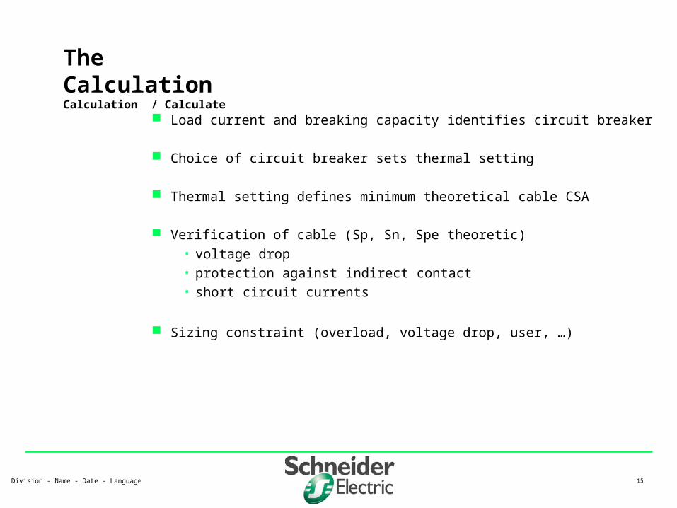
Load current and breaking capacity identifies circuit breaker
Choice of circuit breaker sets thermal setting
Thermal setting defines minimum theoretical cable CSA
Verification of cable (Sp, Sn, Spe theoretic)
• voltage drop
• protection against indirect contact
• short circuit currents
Sizing constraint (overload, voltage drop, user, …)
The CalculationCalculation / Calculate

Division - Name - Date - Language 16
Busbar sizing :
• For main busbar, size is defined by the circuit breaker protection which is defined by the nominal current of transformer (and not the sum of the load currents !)
• For other busbar (sub DB) : sizing according to circuit breaker protection, which is defined by the load current.
Short circuit currents
• Ik max : cold short circuit (copper is cold-low resistivity)
• Ik min : warm short circuit (copper is warm - high resistivity)
• Ik3 : three phase ‘bolted’ fault
• Ik2 : phase - phase fault
• Ik1 : phase - neutral fault
• Earth fault : phase-earth fault
The CalculationCalculation / Calculate

Division - Name - Date - Language 17
The CalculationResistivity values
o : resitivity at 20 degrees Celcius (IEC909)
• copper : 18,51• aluminium : 29,41
At different temperatures :• PVC
1= 1,2x o at 70 degrees
2= 1,38x o at 115 degrees (if S <= 300 mm²)
2= 1,34x o at 105 degrees (if S > 300 mm²
3= 1,30x o at 95 degrees (if S <= 300 mm²)
3= 1,26x o at 85 degrees (if S > 300 mm²)
• PR 1= 1,28x o at 90 degrees
2= 1,60x o at 170 degrees
3= 1,48x o at 140 degrees
Linear reactance (non armoured cables)• multi core or single core in trefoil : = 0,08• single core, flat touching : = 0,09• single core, spaced : = 0,13

Division - Name - Date - Language 18
The CalculationShort circuit currents (values of resistivity to be used)
Ik3max, Ik2max and Ik1max : o
Ik2min and Ik1min
• for circuit protected by fuses : 2
• for circuits protected by circuit breakers : 1
If (earth fault current)• TNC :
– for circuit protected by fuses : 2
– for circuits protected by circuit breakers : 1
• Multicore, PE included
– for circuit protected by fuses : 2
– for circuits protected by circuit breakers : 1
• PE separate
– for circuit protected by fuses : 2
– for circuits protected by circuit breakers : 1
Voltage drop :
• 1

Division - Name - Date - Language 19
B7
Emergency DB
B2
Switchboard
C6
Emergency DB feeder
Q6
Q8
C8
Emergency supply
G8
L9
C9
Vital Load
Q9
M10
C10
Vital Motor
K10
Q10
Q5
Main lighting
C5
D5
Main lighting
E5
Q4
K4
Main motor
C4
M4
Q3
Main Load
C3
L3
Q1
Source
C1
T1
The second study

Division - Name - Date - Language 20
Define new circuits :
• Emergency DB feeder : 45 m , (I = ???)
• Emergency DB
• Emergency supply
• Vital Load (36m, 135A)
• Vital Motor (75m, 18,5 kW mechanical)
Run Power Sum
• Transformer : 400 to 630 kVA
• Generator : 160 kVA (only supplies Emergency board !)
Run Calculation
Modify the circuit

Division - Name - Date - Language 21
Zoom : drag a box around the area to zoom into
Grid
Alf F3 = search for a particular circuit based on its name or ID
Circuit selection (multiple) : keep SHIFT button pressed while selecting multiple circuits, or draw a box around the circuits to select.
Moving circuits : drag and drop the selection
Copying circuits (including the characteristics)
• select circuit to be copied
• CTRL+C and then CTRL+V
• Edit / Copy and then Edit / Paste
Enlarge busbars : select busbar, click on , enlarge bars.
Advanced editing
Division - Name - Date - Language 22
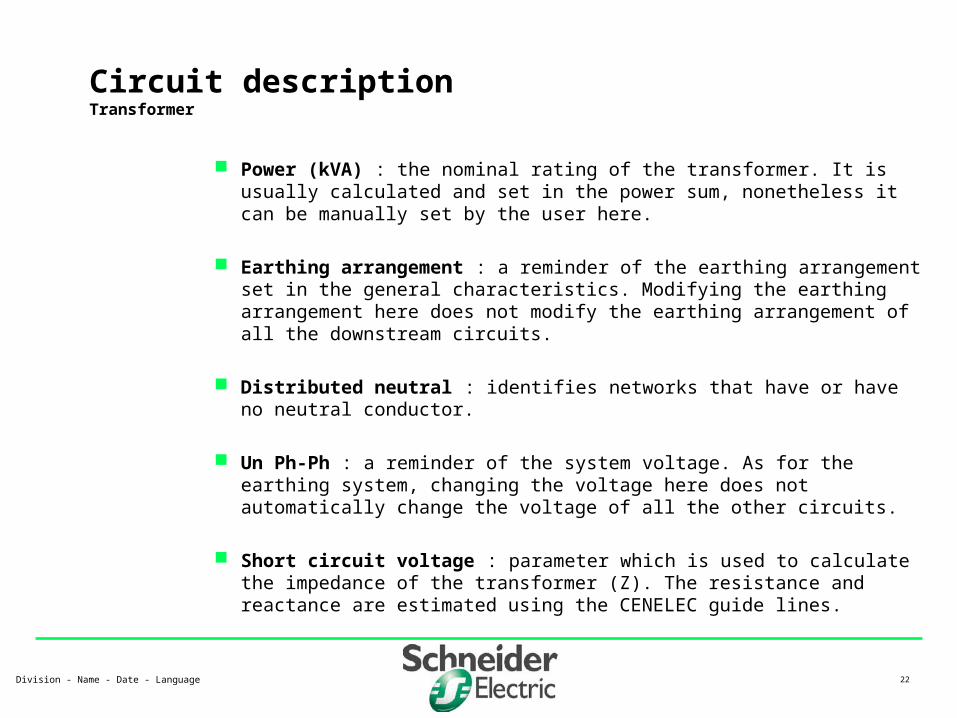
Power (kVA) : the nominal rating of the transformer. It is usually calculated and set in the power sum, nonetheless it can be manually set by the user here.
Earthing arrangement : a reminder of the earthing arrangement set in the general characteristics. Modifying the earthing arrangement here does not modify the earthing arrangement of all the downstream circuits.
Distributed neutral : identifies networks that have or have no neutral conductor.
Un Ph-Ph : a reminder of the system voltage. As for the earthing system, changing the voltage here does not automatically change the voltage of all the other circuits.
Short circuit voltage : parameter which is used to calculate the impedance of the transformer (Z). The resistance and reactance are estimated using the CENELEC guide lines.
Circuit descriptionTransformer

Division - Name - Date - Language 23
Circuit descriptionTransformer (2)
HV Psc : short circuit level on the medium voltage side of the transformer. Enables Ecodial to calculate the impedance (Z) of the medium voltage network
Connection : the different windings of the MV/LV transformer
Power factor : a result of the Power Sum. The power factor at the downstream terminals of the transformer.
System frequency
HV operating time : time used to size the transformer to circuit breaker connection (refers to Electrical Installation Guide table H1-63)

Division - Name - Date - Language 24
Circuit descriptionTransformer (3)
Results :
• R and X of MV network (using CENELEC R064-003 formulas)
– XQ= 0,995 x ZQ RQ=0,1 x XQ
• R and X of transformer (using CENELEC R064-003 formulas)
– RT=0,31 x ZT XT = 0,95 x ZT
• Ib : rated current of the transformer (In)
• Isc max (maximum short circuit current at the terminals of the transformer)
• Copper losses (heat loss)
kQQ S
UnZ
2)05,1(
100
)05,1( 2kr
rTT
u
S
UnZ
TRInPcu 23
Un
SIn rT
3
upstream
kZ
UncIIsc
3
05,1maxmax3

Division - Name - Date - Language 25
Circuit descriptionGenerators
Power (kVA) : see previous
Earthing arrangement : see previous
Distributed neutral : see previous
Un Ph-Ph : see previous
Power factor : see previous.
System frequency : see previous
X’o : Zero phase impedance
X’’ : Transient impedance, used to calculate the short circuit current

Division - Name - Date - Language 26
Circuit descriptionSource
Un Ph-Ph : see previous
Isc max (kA) : maximum short circuit current (Ik3max) at the point of the LV connection from which the study will start.
Power factor : see previous.
System frequency : see previous
Energy supplier : Private substation is the only value.
Distributed neutral : see previous
I service connection (A) : Intensity of the connection, in other words the current rating of the upstream protection device (not drawn on the diagram).

Division - Name - Date - Language 27
Circuit descriptionSource (2)
Isc min upstream (kA) : value of the Ik1min short circuit at the point of connection. This value is used to calculate the ‘warm’ impedance of the Phase/Neutral loop.
Earthing arrangement : see previous.
dU initial (%) : The voltage drop from the transformer to the LV connection from which the study starts. This used to calculate the cumulative voltage drop downstream of the LV connection.
Division - Name - Date - Language 28
Circuit descriptionCapacitor
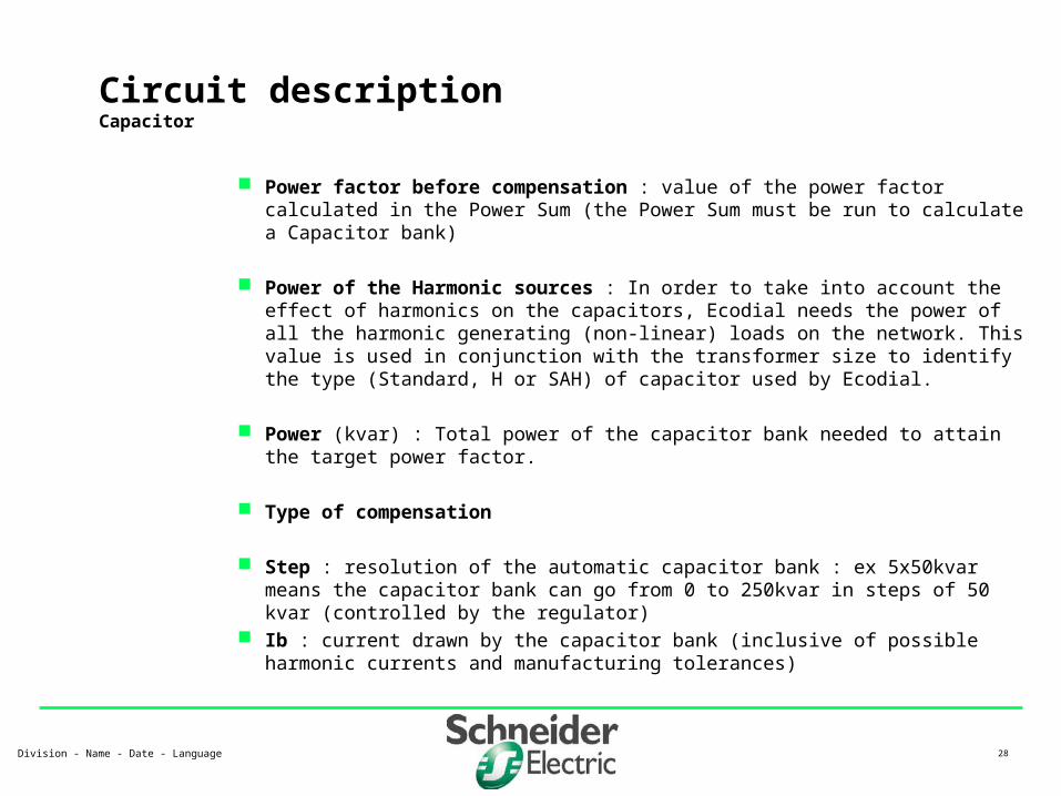
Power factor before compensation : value of the power factor calculated in the Power Sum (the Power Sum must be run to calculate a Capacitor bank)
Power of the Harmonic sources : In order to take into account the effect of harmonics on the capacitors, Ecodial needs the power of all the harmonic generating (non-linear) loads on the network. This value is used in conjunction with the transformer size to identify the type (Standard, H or SAH) of capacitor used by Ecodial.
Power (kvar) : Total power of the capacitor bank needed to attain the target power factor.
Type of compensation
Step : resolution of the automatic capacitor bank : ex 5x50kvar means the capacitor bank can go from 0 to 250kvar in steps of 50 kvar (controlled by the regulator)
Ib : current drawn by the capacitor bank (inclusive of possible harmonic currents and manufacturing tolerances)

Division - Name - Date - Language 29
Circuit descriptionCapacitor
Ih L, C,
Transformer(PT)
Capacitor(Q)
Harmonic current injection
Equivalent impedance of L-C circuit (resistances ignored)• Z= j.L./ (1-L.C.²)
Resonance when ²=(2f)²=LC (Zmax induces to Voltage max)• order of resonance :
• if order of resonance is close to harmonic current injection, filtering devices could be required.
Harmonic voltage created across the equivalent impedance of the transformer and capacitor, which causes circulating currents in the L-C loop, which can be a cause of nuisance tripping in transformer or capacitor protection devices.
c
T
Qucc
Pn
(%)
Circuit descriptionCapacitor
Circuit descriptionCapacitor
Vh

Division - Name - Date - Language 30
Circuit descriptionCircuit breaker (distribution)
Range : Product range from which the circuit breaker is to be chosen. If Ecodial cannot find a breaker in that range it will look for a breaker in a predefined range (function of the demand current)
Designation : name of circuit breaker Trip unit / curve : name of the trip unit or curve of the circuit breaker Nb of poles protected : polarity of the circuit breaker that is required. Earth leakage protection : if earth leakage protection (RCD) is required (by user,
or for a particular application, switch this characteristic to YES). Fire protection : this is a characteristic that will force an earth leakage device,
and set it to ensure that a leakage current will not be able to cause a fire (threshold < 300mA)
• Integrated with the protection device : certain RCDs are integrated (NS Vigi, …) and certain are separated (RH***). The user can choose the type of RCD required. By default, Ecodial looks for integrated RCDs, and then separated RCDs if unsuccessful.
• Class : (A / AC ) defines the sensitivity of the RCD to continuous and pulsed DC signals.
• Earth leakage protection device : name of the device ensuring the function of RCD.

Division - Name - Date - Language 31
• Sensitivity (mA) : pickup current of the RCD device
• Delay (ms) : time delay before disconnection under earth fault conditions I thermal setting (A) : Thermal setting of the circuit breaker. This value is set to
be greater or equal to the demand current, and is used to size the cable. I magnetic setting (A) : magnetic setting of the circuit breaker. This setting s
made to ensure protection against indirect contact in TN, and to ensure correct motor starting based on start-up currents.
Frame rating (A) : maximum rating of the circuit breaker frame Trip unit rating (A) : maximum setting of the trip unit. Ir : position of the thermal adjustment on the trip unit Io : position of the thermal adjustment on the trip unit Im/Isd : position of the magnetic adjustment on the trip unit Motor mechanism : breakers must be able to be fixed with a motor mechanism
Circuit descriptionCircuit breaker (distribution) (2)

Division - Name - Date - Language 32
Cascading requested :
• YES : circuit breaker is chosen using cascading with the upstream device (only the device directly upstream)
• NO : circuit breaker is chosen based on its stand-alone breaking capacity.
Discrimination requested :
• YES : circuit breakers that have better discrimination potential are selected instead of normal circuit breakers
Installation : Fixed breakers or withdrawable breakers
Circuit descriptionCircuit breaker (distribution) (3)

Division - Name - Date - Language 33
Circuit descriptionCircuit breaker (motor)
Range : see previous Designation : see previous Trip unit / curve : see previous Contactor : name of contactor to be used according to the co-ordination tables Thermal protection : name of thermal overload (if needed) according to co-
ordination tables. Soft starter : name of soft starter (if needed) according to co-ordination tables. Earth leakage protection : see previous. Fire protection :see previous with the added safety that the tripping time is
delayed by at least 60ms to ensure there is no nuisance tripping on start-up. Number of poles protected : always 3P3T, as Ecodial does not cover single
phase motors I thermal setting (A) : Thermal setting of the circuit breaker. This value is set to
be greater or equal to the demand current, and is used to size the cable. I magnetic setting (A) : magnetic setting of the circuit breaker. This setting s
made to ensure protection against indirect contact in TN, and to ensure correct motor starting based on start-up currents.

Division - Name - Date - Language 34
Frame rating (A) : maximum rating of the circuit breaker frame Trip unit rating (A) : maximum setting of the trip unit. Ir : position of the thermal adjustment on the trip unit Io : position of the thermal adjustment on the trip unit Im/Isd : position of the magnetic adjustment on the trip unit Motor mechanism : breakers must be able to be fixed with a motor mechanism Cascading requested :
• YES : circuit breaker is chosen using cascading with the upstream device (only the device directly upstream)
• NO : circuit breaker is chosen based on its stand-alone breaking capacity. Discrimination requested :
• YES : circuit breakers that have better discrimination potential are selected instead of normal circuit breakers
Installation : Fixed breakers or withdrawable breakers
Circuit descriptionCircuit breaker (motor) (2)

Division - Name - Date - Language 35
Circuit descriptionLoad
Number of identical circuits : instead of drawing multiple feeders having EXACTLY the same characteristic, just draw one !
Ib : demand current of the load (calculated from the power and polarity)
Circuit polarity : polarity of the load
Earthing arrangement : see previous
Power (kVA) : demand power (calculated from the current and the polarity)
Power factor : power factor of the load (.8 is default value)
Fixed / Mobile :
• Fixed : permanent connection from installation to load.
• Mobile : terminal load is fed through a power socket (special earth leakage conditions are then applicable : 30mA and Instanataneous protection is required)

Division - Name - Date - Language 36
Circuit descriptionMotor
Number of identical circuits : see previous Mechanical power (kW) : rated mechanical power of motor Type of starting : for Direct on Line or Soft Starting applications Motor efficiency : ratio between mechanical and electrical power (in kW) Ib (A) : full load current of motor Power factor : full load power factor of the motor Circuit polarity (always 3P) Earthing arrangement : see previous Power (kW) : demand power (calculated from the efficiency) Type of co-ordination : Type 1 or Type 2 Starting class : Standard / Long Start-up current : sets the magnetic setting of the breaker

Division - Name - Date - Language 37
Circuit descriptionLighting
Number of identical circuits Lighting Source : type of lamp Individual lamp power : Number of lamps per light : for each lighting point there can be several lamps Nb of lights (A) : total number of lamps on the Canalis lighting line Ib : full load current at the origin of the Canalis lighting distribution Ballast power : for lamps using ballasts (fluo tubes, …) Circuit polarity Earthing arrangement Power (kW) : total demand power (calculated) Power factor

Division - Name - Date - Language 38
Circuit descriptionVariable Speed Drive
Reference : name of VSD Nominal power of the VSD (kW) : characteristic of VSD Ib : current drawn by VSD (including harmonics) Absorbed power : total power drawn by VSD (motor power and heat loss) Torque (A) : starting torque : High or standard Form factor : ratio between total RMS and 50Hz signal (characteristic of VSD) Is permanent : output current Is max permanent : maximum permanent output current (characteristic of VSD) Is max 60s : maximum 60s output current (characteristic of VSD) Earthing arrangement Circuit polarity

Division - Name - Date - Language 39
Circuit descriptionCable
Length : length of the cable (Short circuit and voltage drop calculations) Installation method : code for the type of installation. Defines the standard
derating factors and the type of conductors used. Insulation : sets the insulation material of the cable (impedance calculation) Type of conductor : output from the Installation method, not an input ! Neutral loaded : source of derating on 3P+N networks Conductor arrangement : calculation of the linear reactance of the cable Type of PE : influences the type of cables selected by Ecodial Number of additional circuits : cable derating Number of layers : cable derating K user : additional cable derating (over and above the standards) Ambient temperature : cable derating Delta U max on circuit (%) : maximum voltage drop allowed on the cable Reference : name of cable

Division - Name - Date - Language 40
Circuit descriptionCable (2)
Nb Ph conductor : calculation result CSA Ph conductor : calculation result Nb N conductor : calculation result CSA N conductor : calculation result Nb PE conductor : calculation result CSA PE conductor : calculation result Phase metal : cable characteristic (input) Neutral metal : cable characteristic (input) PE metal : cable characteristic (input) Safety voltage : 50V or 25V

Division - Name - Date - Language 41
Ecodial and the earthing schemesImplementing protection against indirect contact
TT
• Earth fault current (leakage) calculated using the impedance of the source and earth electrodes, and the Phase-Earth conductor impedance
• Standards require an RCD device on the main incomer
the earth and source electrodes must not be interconnected ! TN
• Earth fault current calculated using the Phase-Earth conductor impedance
• Protection against indirect contact insured by setting the magnetic under the Earth fault current
• Trip units can be changed to ensure accurate magnetic threshold is used
• RCDs can be implemented IT (2nd fault)
• identical calculations as for the TN system
• Earth fault current is calculated assuming both fault occur at the same point. This ensures ‘worse case scenario’ as if the second fault appears further away, the real fault current on the 2nd fault would be greater than the calculated fault current corresponding to the 2nd fault location, and ensuring tripping by the 2nd fault location protection device.

Division - Name - Date - Language 42
Calculation rulesPhase CSA
a
m
Irth
KSth
11
Theoretical Phase CSA : calculated by a formula, where (IEC 60364-5-523-B):
• K is the total derating (temperature laying method, cables in parallel, …)
• Irth : is the thermal setting of the upstream breaker
• m and a : parameters defined by the laying method and the type of cable (metal, insulator) andthe number of loaded conductors in the circuit)
Choice of Phase conductor
• based on cable database supplied
• based on theoretical phase CSA and tolerance
• based on installation rules (ex TNC Smini = 10mm²)
• based on limits implied in the standards (ex Smini for multicore conductors on perforated tray = 25mm²)
• based on maximum phase CSA allowed
Voltage drop is calculated on this cable using demand current
• CSA could be increased

Division - Name - Date - Language 43
Calculation rulesNeutral CSA
Theoretical calculation made by Ecodial
• minimum theoretical CSA equal Ph or Ph/2
Warning : the Neutral as any cable should be sized according to the upstream protection setting (this is to ensure safety, not continuity !).
• With 4p4t CB, the neutral can be of the same CSA of the Phase
• With 4p3t 1/2N, the neutral can be half
• With 3p devices (Neutral not protected), there is an unknown, as there is no direct protection on the neutral…
Phase unbalance can lead (worse case scenario) to a phase current equal to neutral current, so Neutral should be at least equal to Phase
Triplen Harmonics (3rd, 9th, …) add up on the neutral. Therefore, if the phase is ONLY 3rd harmonics, neutral current = 3x phase current. In reality, the neutral current will usually be less than 1.7-1.8 times the phase current, example ;
• Irms (phase) = (I1, I3 (80%), I5(45%), I7(12%)) = 1.36x I1
• Irms (neutral) = 3x I3 = 2.4x I1 = 1.76 Irms (phase)

Division - Name - Date - Language 44
Calculation rulesNeutral CSA
Recommended actions :
• use half neutrals
– when there is a 4p3t N/2 circuit breaker protecting the circuit,
– and if there is no possibility of excessive phase unbalance and/or triplen harmonic loading on the circuit.
– Note : 3p3t are acceptable solutions, but 4p3t N/2 offer more safety under unexpected conditions
• use full neutrals
– when there is a 4p4t circuit breaker protecting the circuit
– and if there is a possibility of excessive phase unbalance, or limited triplen harmonic (max allowed = 33% triplen in the RMS)
– Note : 3p3t are acceptable solutions, but 4p4t offer more safety under unexpected conditions
• use double neutrals
– with 3p3t circuit breakers
– when there is a high risk of excessive triplen harmonic

Division - Name - Date - Language 45
Calculation rulesPE CSA
Automatic minimum PE :
• if Ph 16mm², PE = Ph x kph/kpe
• if Ph 35 mm², PE = 16mm² x kph/kpe
• if Ph > 35 mm², PE = Ph/2 x kph/kpe
• where kph and kpe function of the type of phase and earth conductor (metal, insulation, single/multi core, …)
• in TT, max PE = 35mm²
Theoretical minimum PE : the theoretical minimum PE cross section should only verify the I²t < k²S² condition, as no current is ever expected to flow on the PE (as it is an equipotential link). This condition usually implies small PE cross sections (+/- 4mm² in TN and 1mm² in TT). Using such small cables has two bad consequences :
• reducing Earth fault current (due to higher impedance), which could require the use of earth fault protection devices or lowering the magnetic thresholds to non efficient levels (motor starting and discrimination problems)
• creating a higher voltage differential on the PE due to natural leakage currents
Ecodial chooses automatically the CSA given above, but allows smaller cables to be selected by the user.

Division - Name - Date - Language 46
Network
• General characteristics
– TNC
– 400V
• Transformer
– 800kVA transformer
– Incomer cable length = 0
• Load
– 3P+N
– 100A
– Installation method EJ(1)
Calculate the network with :
• Load cable length =30m, 100m, 140m, 170m
• Info needed : Irm, If, Sph, Spe, DeltaU, CB, Sizing criteria
Tableau
B2
T1
C1
Circuit
Q1
Q3
Circuit
C3
L3
Calculation examplesthe effect of long cables

Division - Name - Date - Language 47
Calculation examplesthe effect of long cables
Cable sized on load current
Cable sized on voltage drop
Setting of trip unit to cater for low earth fault current
(protection against indirect contact)
• To ensure disconnection in sufficient time, Ecodial verifies that the earth fault current is higher than the magnetic setting of the breaker (including tolerance).
• Trip units can be changed to ensure this :
– C curve to B curve
– TM to STR
• cable size can be increased
• If no solution is found Ecodial interrupts the calculation requesting the user to manually place an RCD on the circuit breaker to ensure disconnection, and therefore protection against indirect contact.

Division - Name - Date - Language 48
Non-uniformly distributed load
• the Icc and DeltaU can be calculated at each tap-off point, or for worst case scenario (Icc at source)
• Calculation method to be used for distribution systems having loads that vary substantially in power and location.
Uniformly distributed load
• the Icc is calculated at the beginning of BTS.
• The voltage drop is estimated as a function of the number of tap-offs
• Calculation adapted for distribution systems having evenly distributed loads (in power and location)
Calculation examplesPrefabricated busbar trunking

Division - Name - Date - Language 49
Uniformly and Non-uniformly distributed load.
• 800kVA
• 100A tapoffs
• D=5,10,15,20,25
• Total length 30m
• Info needed :
– Icc, deltaU per tap/off.B2
Tableau
D4
CEP
Q8
Circuit
C8
L8 L9
C9
Circuit
Q9
Q7
Circuit
C7
L7L6
C6
Circuit
Q6
Q5
Circuit
C5
L5
Q3
Circuit
C3
Q1
Circuit
C1
T1
Calculation examplesPrefabricated busbar trunking (2)

Division - Name - Date - Language 50
Ku : usage coefficient
• applicable to a CIRCUIT
• % full load current when load is running
• example :
– motor +/- 80%
– Light 100%
Ks : diversity coefficient
• applicable to a DISTRIBUTION BOARD
• chance of all feeders drawing maximum load at any given time
• relative to the number of feeders on DB.
• See Electrical Installation Guide
Calculation parametersDiversity and usage coefficients

Division - Name - Date - Language 51
Lathe 1 5.5 kWLathe 2 5.5 kW
Distribution box Lathe 3 5.5 kWLathe 4 5.5 kW
Workshop A Drill 1 2.2 kWDrill 2 2.2 kW
3x socket outlet circuit (1P+N) 20 A each6x lighting lines (1P+N) 10x 100W each
Compressor 15 kWIncomer Workshop B 5x socket outlet circuit (1P+N) 20 A each
4x lighting lines (1P+N) 4x 100W each
Ventilation Fan 1 2.2 kWDistribution box Ventilation Fan 2 2.2 kW
Oven 1 15 kWWorkshop C Oven 2 15 kW
10x socket outlet circuit (1P+N) 20 A each2x lighting lines (1P+N) 2x 100W each
Calculation parametersDiversity and usage coefficients - example
Division - Name - Date - Language 52
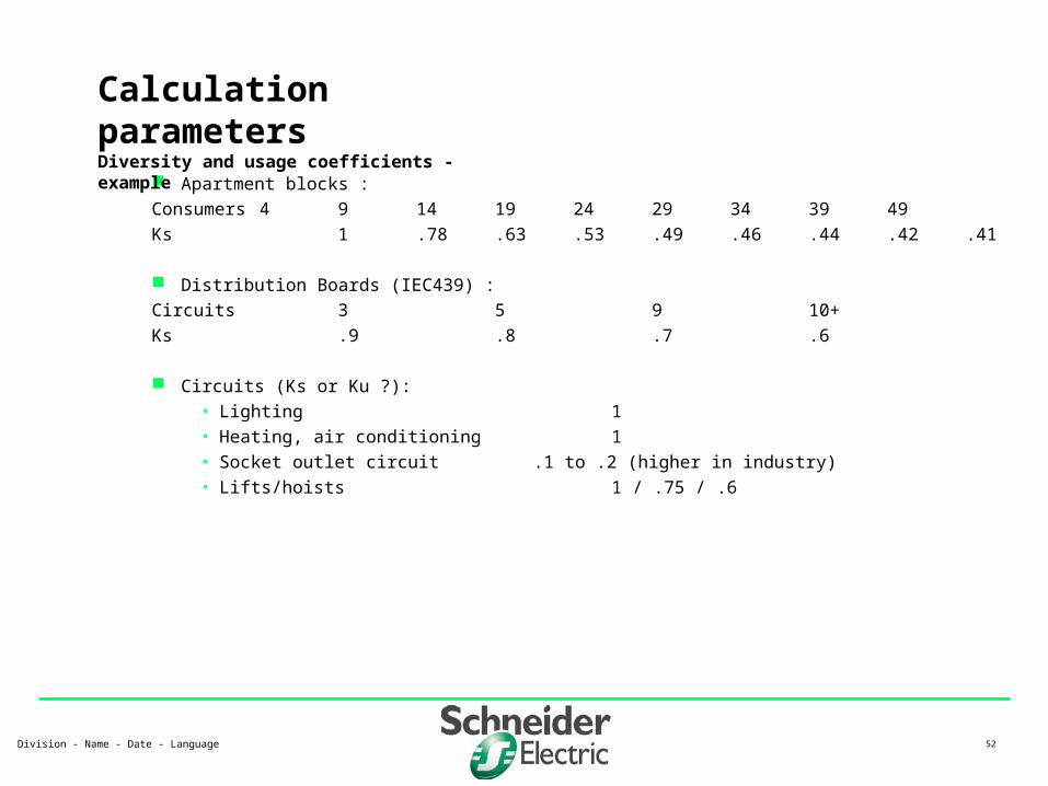
Apartment blocks :
Consumers 4 9 14 19 24 29 34 39 49
Ks 1 .78 .63 .53 .49 .46 .44 .42 .41
Distribution Boards (IEC439) :
Circuits 3 5 9 10+
Ks .9 .8 .7 .6
Circuits (Ks or Ku ?):• Lighting 1• Heating, air conditioning 1• Socket outlet circuit .1 to .2 (higher in industry)• Lifts/hoists 1 / .75 / .6
Calculation parametersDiversity and usage coefficients - example

Division - Name - Date - Language 53
Problem with Ku and Ks
• Responsibility of the user
• Personal experience
• Knowledge of installation
• Database of existing installations
Advantage of Ku and Ks
• more cost effective installation
• not oversized
• Example
– total installed power : 144kVA
– maximum expected demand : 80 kVA
Calculation parametersDiversity and usage coefficients - example

Division - Name - Date - Language 54
The algorithms used by Ecodial
Formulas, constants
• impedance
• Icc, voltage drop, ..
Reference to standards
Calculation guidesSpecial help file

Division - Name - Date - Language 55
Different types of information : The front page Header and footer The device lists Equipment display Calculation notes The single-line diagram
Printing : Customise the setup Choice of language
Output

Division - Name - Date - Language 56
Open and save a project How to make a link between projects ? Choice of interface language The summary Different kinds of exports :
DXF RTF ECD
Special
Division - Name - Date - Language 57
Circuit breaker and busbar selection Discrimation and cascading tables Tripping curves
Guides and tools
Division - Name - Date - Language 58
Maximum number of circuits in a project : 70 Maximum number of copied circuits : 20 Maximum number of transformers : 4
Limitations

Division - Name - Date - Language 59
Normal and emergency sources
• Ecodial uses the worst case scenario to select equipment :
– max short circuit level from Transformers
– min earth fault current from Generators
Complex networks It is not always possible to draw the exact network. It can be necessary
to draw a simplified network, and define the final network based on these calculations.
Special applications