Dynamic Reactive Power Control -...
46
Dynamic Reactive Power Control By V. R. Kanetkar Full Time Consultant – Technical Services at Veretiv Energy Private Limited Thane (West)
-
Upload
nguyenhanh -
Category
Documents
-
view
215 -
download
1
Transcript of Dynamic Reactive Power Control -...

Dynamic Reactive Power
Control
By
V. R. Kanetkar
Full Time Consultant – Technical Services at
Veretiv Energy Private Limited
Thane (West)

Acknowledgement
The author acknowledges with deep gratitude the experience he gathered while working with M/s L&T (1978-89), ABB Ltd India (1995-2009), Autometers Alliance Ltd (2009-12), Shreem Electric Limited (2012-16), and Vertiv Energy Private Limited (2016 onwards) and the opportunities offered by them towards drawing this long experience in power electronics, especially in R&D.
The author also acknowledges the contribution made to his professional life by all the engineers with whom he had an opportunity to work and his teachers from whom he learnt the value and impact the knowledge and experience can make.
Product photographs shown here are of the products on which he worked during his tenure with ABB Ltd India. He hopes that ABB Ltd India will not have any objection as these are shown here only to support the presentation subject and without any commercial angle attached. The author expresses his deep gratitude to ABB Ltd India and extends his apology to ABB Ltd India that these are shown without their written permission, though for a good engineering cause.

Power Quality is related to any deviation from the normal voltage
and frequency of the supply system.
Power Quality Issues
• Varying reactive power causing terminal voltage and power factor variation,
flicker, and additional losses in upstream system
• Current harmonics causing losses, voltage distortion, and system resonance
• Unbalanced currents giving rise to neutral currents and lifting the neutral
potential dangerously with respect to earth
• Sudden voltage dips / rises and frequency changes
• Voltage sags, swells, brownouts, and blackouts

Loadvs = Vmsinwt
wLs
vt
+
-
is
Vs
Is
Isa
Isr
Is
Locus of Vt
Variation in terminal voltage Vt with supply current is at 360 powerangle range
(a) Source voltage supplying current is at
lagging power factor
Vt
Vs
(b) Locus of Vt
Vs
Vt

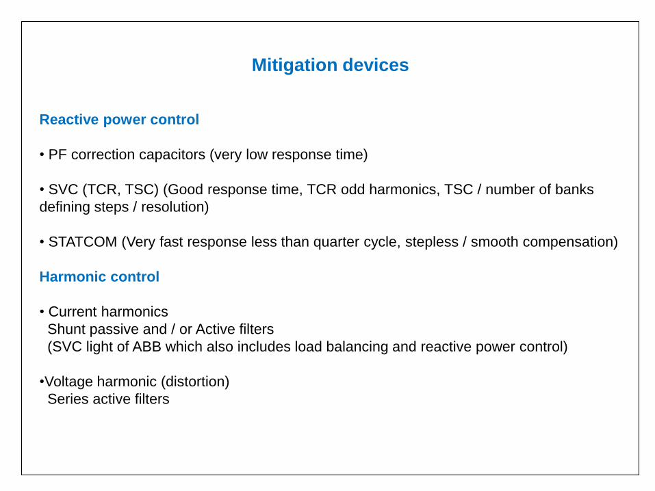
Mitigation devices
Reactive power control
• PF correction capacitors (very low response time)
• SVC (TCR, TSC) (Good response time, TCR odd harmonics, TSC / number of banks
defining steps / resolution)
• STATCOM (Very fast response less than quarter cycle, stepless / smooth compensation)
Harmonic control
• Current harmonics
Shunt passive and / or Active filters
(SVC light of ABB which also includes load balancing and reactive power control)
•Voltage harmonic (distortion)
Series active filters

Voltage sag, swell, small interruptions / momentary voltage dips (0.6 to
1.5 secs)
• SVR (Low power levels, say few MVA / LV / part of MV)
•DVR (Medium to high power levels, say 50 to 60 MVA , MV and HV)
Response time 1 msecs to few msecs
Other devices
• TCSC for damping power system oscillations, mitigating sub synchronous resonance,
and improving stability of two power grids connected together
• Unified Power Flow Controller
• Surge arresters for voltage transients
• Solid state transfer switch
• UPS and BESS (Battery energy storage systems)
• Superconducting magnetic storage systems
• Solid state circuit breakers
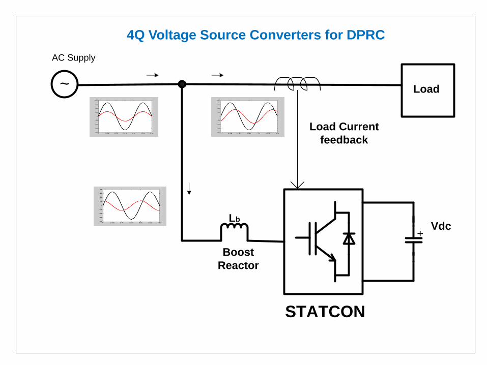
~
Load
Lb
STATCON
Boost
Reactor
Vdc+
Load Current
feedback
AC Supply
4Q Voltage Source Converters for DPRC

0 0.005 0.01 0.015 0.02 0.025 0.03-400
-200
0
200
400
Vsource
0 0.005 0.01 0.015 0.02 0.025 0.03-100
-50
0
50
100
Vcomp
0 0.005 0.01 0.015 0.02 0.025 0.03-400
-200
0
200
400
Vload

Unified Power Flow Controller (UPFC)

Concentrate on Reactive Power Control
(Dynamic), which is more important for us.
This is called as “DRPC”.

Reactive Power equivalence to a glass of beer

Loadvs = Vmsinwt
wLs
vt
+
-
is
Vs
Is
Isa
Isr
Is
Locus of Vt
Variation in terminal voltage Vt with supply current is at 360 powerangle range
(a) Source voltage supplying current is at
lagging power factor
Vt
Vs
(b) Locus of Vt
Vs
Vt

Why is Reactive Power Compensation required?
• Reduction in transformer or supply currents to improve power factor
and reduce associated penalty
• Reduction in transformer or supply currents to reduce maximum kVA
demand
• Reduction in transformer or supply currents so that more load can
be added
• Reduction in transformer and supply currents to reduce losses in the
system
• Improvement of the voltage profile and reduction in flicker (better
voltage stability)
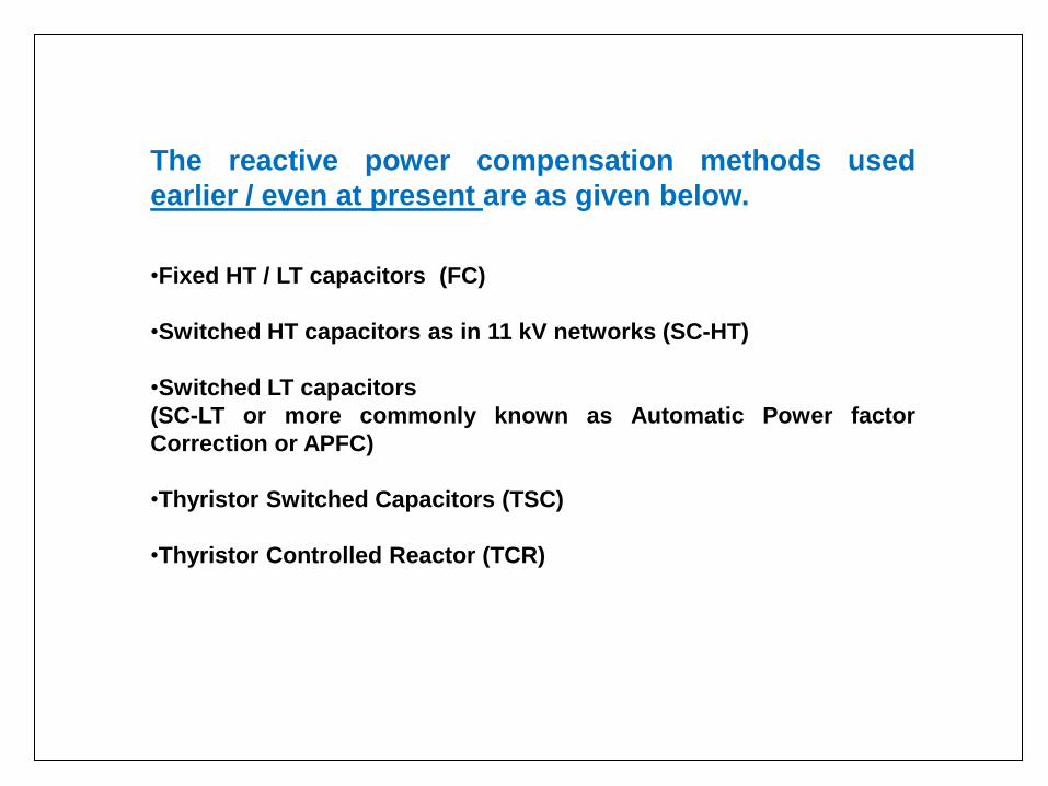
The reactive power compensation methods used
earlier / even at present are as given below.
•Fixed HT / LT capacitors (FC)
•Switched HT capacitors as in 11 kV networks (SC-HT)
•Switched LT capacitors
(SC-LT or more commonly known as Automatic Power factor
Correction or APFC)
•Thyristor Switched Capacitors (TSC)
•Thyristor Controlled Reactor (TCR)

Compensation
requiredC
om
pe
nsa
tio
n d
em
an
d/r
esp
on
se
APFC response(Automatic Power factor
Correction eqpt.)
STATCON
and TCR
t
TSC response is
similar to APFC,
but w/o any
delay

Fixed capacitor and APFC
C1 C2 C3
APFC FC
Logic
Controller
Load3 phase
AC SupplyLoad
Load CT
feedback

Fixed Capacitor / APFC based compensation
• Low dynamics involved, hence suitable for slow varying loads
• High inrush currents and voltage transients due to contactor switchings affecting
life of the capacitors as well as equipment connected on the same bus
•Considerable under and over-compensation for varying loads
•Resonance with supply short circuit impedance
•Harmonic amplification
•kVAR delivery is supply voltage dependent (proportional to square of the supply
voltage) which produces inaccuracy in overall kVAR compensation
•Ageing problems of capacitors resulting in less kVAR
•Considerable maintenance
This method of reactive power compensation is, however, quite economical if there is not much of reactive
power variation and if the disadvantages are not affecting the system.
The capacitors need to be sized based on the required base compensation, voltage variation, and current
harmonics to be absorbed (using a series reactor with tuning frequency maintained below the lowest harmonic
frequency).
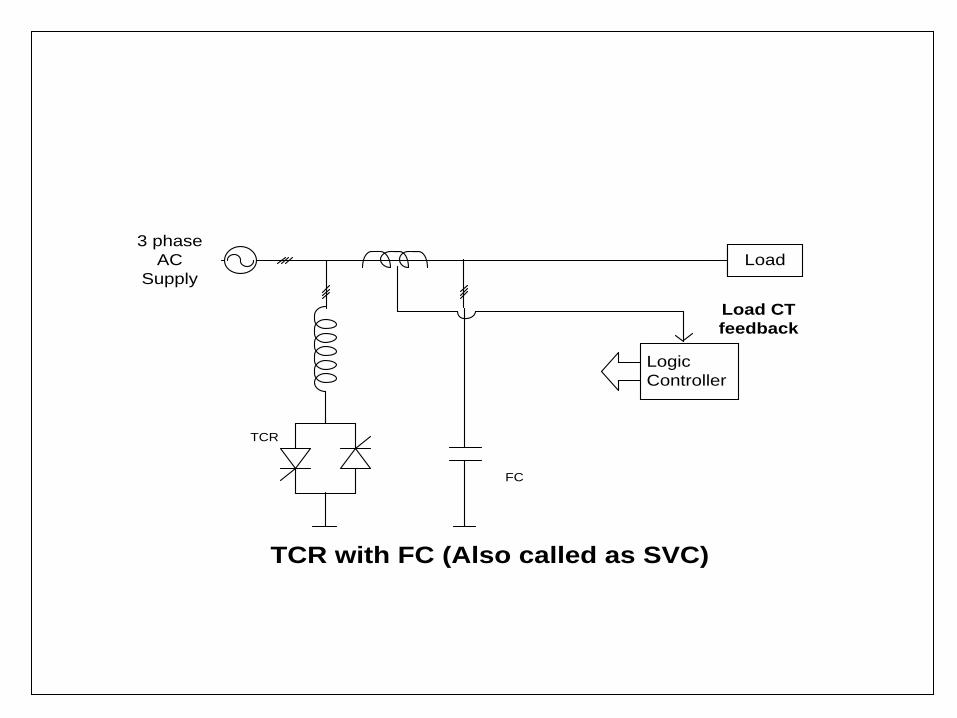
Load
3 phase
AC
Supply
Load
Load CT
feedback
TCR with FC (Also called as SVC)
TCR
FC
Logic
Controller

TCR based compensation
• Suitable for fast dynamically varying loads (arc furnace), but at the cost double kVAR installed
capacity and lower order harmonics produced (normally, hence, preferred for very high
compensation requirements such as 30 MVAR and beyond)
• Compensation kVAR to be installed is double the actual kVAR requirement
• Resonance with supply short circuit impedance
• Harmonic amplification
• Not economical for low and medium power kVAR compensation
• Capacitor kVAR delivery is supply voltage dependent (proportional to square of the supply
voltage) which produces inaccuracy in overall kVAR compensation
• Ageing problems of capacitors resulting in less kVAR and compensation inaccuracy
• Considerable maintenance
This method of reactive power compensation is definitely better than the first three methods, but
also involves more installation cost. It offers good response time and is normally used for higher
MVAR compensation (greater than 10 MVAR at least).

Load
3 phase
AC
Supply
Load
Load CT
feedback
C1 C2 Cn
TSC
Logic
Controller

TSC based compensation
•Not suitable for load dynamics of the order of seconds (due to discharge time of
capacitors for switching duty) unless control is designed for it.
•Can result in under and over-compensation for varying loads due to step response,
unless steps are properly worked out.
•Resonance with supply short circuit impedance and harmonic amplification, if not
designed properly.
• Can result in high inrush currents and voltage transients unless proper
synchronization is not taken care of in the design
• kVAR delivery is supply voltage dependent (proportional to square of the supply
voltage) which produces inaccuracy in overall kVAR compensation
• Ageing problems of capacitors resulting in less kVAR and compensation
inaccuracy
•Considerable maintenance unless capacitor designs / selection is properly done
This method of reactive power compensation is definitely better than the first two
methods, but also involves more installation cost.

250 kVAR TSC simulation results

TSC Control


Transition from lagging to leading in one cycle

~
Load
Lb
STATCON
Boost
Reactor
Vdc+
Load Current
feedback
AC Supply
4Q Voltage Source Converters for DPRC

Lbi
c1
+
-v
i1v
s = V
m sin t
+
-
Equivalent circuit for the compensating reactive
current drawn by STATCON
Non
Linear
Load
Vdc
+
AC
Supply
Lb
vs
IGBT PWM Voltage Source Converter
Boost Reactor
is1
iL1
ic1
SC Imp.
Ls
Load current CT
feedback
STATCON
Single line diagram for a typical load using STATCON
vi1
IL1
sin IL1
IC1
= -IL1
sin
Vs
-(IC1L
b)
Vi1
Vector diagram for capacitive compensation
( Load demands inductive power
STATCON provides capactive compensation)
IL1sinIL1
IC1= -IL1sin
Vs
-(IC1Lb)
Vi1
Vector diagram for inductive compensation
(Load demands capactive power
STATCON provides inductive compensation)
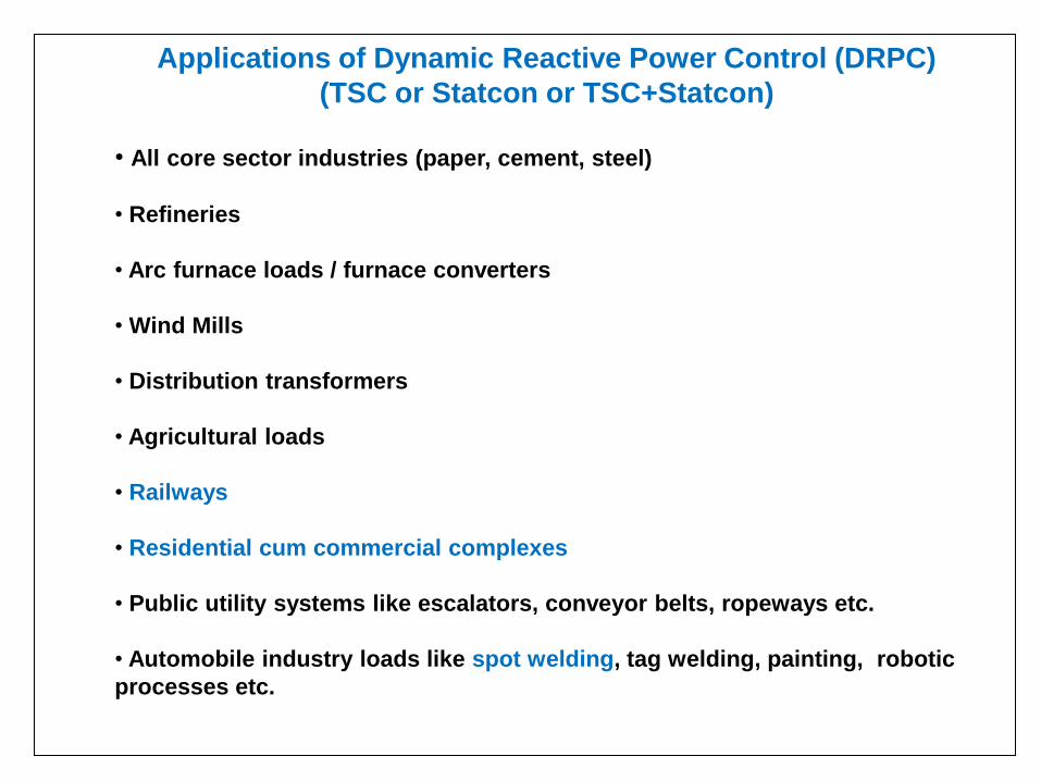
Applications of Dynamic Reactive Power Control (DRPC)
(TSC or Statcon or TSC+Statcon)
• All core sector industries (paper, cement, steel)
• Refineries
• Arc furnace loads / furnace converters
• Wind Mills
• Distribution transformers
• Agricultural loads
• Railways
• Residential cum commercial complexes
• Public utility systems like escalators, conveyor belts, ropeways etc.
• Automobile industry loads like spot welding, tag welding, painting, robotic
processes etc.

~
~
van
vcn
Lb
vdc
+
+
-
-
~
vbn
+-
+
+
+
-
Cd
1
Cd
2
S1
C
S2
C
S1b
S2b
S1a
S2a
Cd1 Cd2 Cd
Three phase half bridge two level Voltage Source Converter
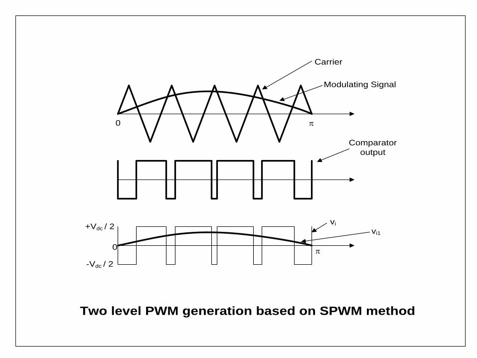
Carrier
vi
vi1+Vdc / 2
-Vdc / 2
0
0
Two level PWM generation based on SPWM method
Modulating Signal
Comparator
output

~ van
Lb
+
-
S3a
S4a
S1a
S2a
vdc+
+
-
Cd
Single phase full bridge three level Voltage Source Converter

Modulating Signal
Comparator output
Carrier
vi
vi1+Vdc
0
0
Three level PWM generation based on SPWM method
-Vdc
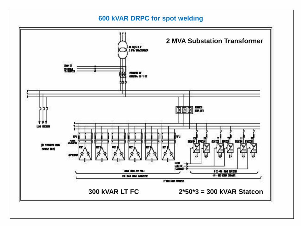
2*50*3 = 300 kVAR Statcon 300 kVAR LT FC
2 MVA Substation Transformer
600 kVAR DRPC for spot welding
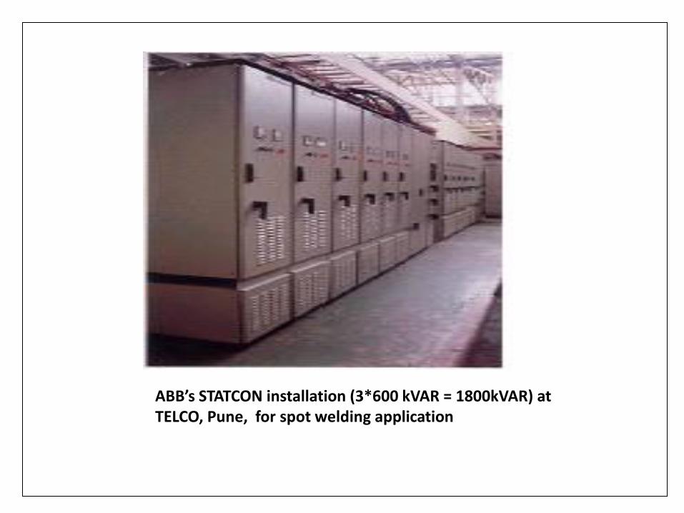
ABB’s STATCON installation (3*600 kVAR = 1800kVAR) at TELCO, Pune, for spot welding application

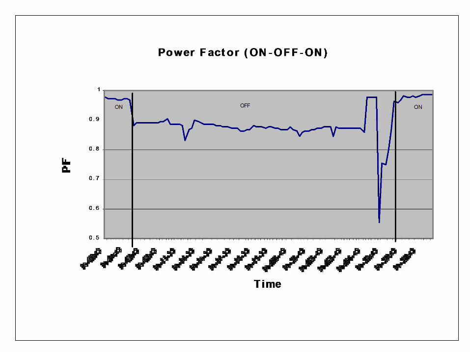
Lead (capacitive) Lag (inductive)
Lag to Lead transient Spot welding dynamics


ABB’s 3 MVAR DRPC system at Lasalgaon CR substation (1800 kVAR detuned HT FC + 150 KVAR*8 LV side 430 V Statcon)


Some statistics (Indian Scenario) • Need over 330000MW
• Installed capacity 155000 MW
• The shortfall cannot be covered even with 15000 MW / annum
• T&D losses 22-33%
• MoP (GoI): Focus hence on distribution
• At 125000MW average availability and 0.8 pf, RP= 93750 MVAR
• Even with 10% of this RPC considered as DRPC, the value is 9375 MVAR
•With Rs 4000/- kVAR for DRPC, the available DRPC market is 3750 Crores
(pessimistic assumption)
• It will be growing market at the rate of 450+ Crores / annum
Approximate prices per kVAR
FC : Rs 300 – 800 / kVAR (LT)
and Rs 45 -70 / kVAR (HT)
APFC: Rs 900 – 1200 / kVAR
TSC : Rs 1400 – 1600 / kVAR
Statcon: Rs 3000 / kVAR

DRPC in Indian Railway 25 kV TSS
Specifications:
25 kV (variation 28 to 19 kV) , 3000 – 4500 kVAR , required pf > 0.9 or 0.92
Suppliers:
ABB offers detuned HT side FC and Statcon with (25 kV / 430 V) transformer
Shreem Capacitors offers TSC with 2 * ( 25 kV / 415 V) transformers
Analysis:
(1) TSS transformer 132 kV / 25 kV, 800 A, 20 MVA (Normal load reaches 600 A ,
sometimes crosses 600A)
25 kV, 600 A, 0.7 pf, + 4500 kVAR => 0.86 pf
25 kV, 600 A, 0.8 pf, + 4500 kVAR => 0.94 pf
25 kV, 600 A, 0.7 pf, + 8075 kVAR => 0.97 pf
25 kV, 800 A, 0.7 pf, + 10775 kVAR => 0.97 pf

(2) Typical comparison between “ABB Statcon based DRPC at 4500 kVAR” and “AAL TSC /
TSC +Statcon”
ABB system: 2100 kVAR (=150 kVAR*14) Statcon + 2400 kVAR HT FC
Other major components: 3 MVAR transformer, 13% detuned reactor at HT, HT
breakers for HT FC and transformer primary, and CT
Equivalent AAL system: (1) 5250 kVAR (=250 kVAR*21) TSC
(2) 5000 kVAR (=250 kVAR*20) TSC + 250 kVAR Statcon
Other major components: 5.5 MVAR transformer, HT breaker, and CT Option (2) is neglected as the Statcon affects pf in third digit and accuracy of pf is not important.
Typical comparison with “ABB DRPC at 4500 kVAR”
ABB AAL / TSC
19 kV, 800 A, 0.7 pf => 0.805 0.805
28 kV, 600 A, 0.8 pf => 0.944 0.9674
FL loss at 25 kV in kW 90-100 90-100
NL loss at 25 kV in kW 90-100 12-18
(Statcon in full inductive mode)
Cost Rs in Lakhs 220+ 200-220
(inclusive of HT breaker, LT breaker, CT, Room
Auxiliaries, controller(s), displays, miscellaneous)

Thank You
For
Your Patience