Determining Recovery Potential of Dredged Material for ...
19
PURPOSE: Dredged material stored in confined disposal facilities (CDFs) often contains signifi- cant amounts of trash and debris. Removal of this trash and debris is usually necessary to upgrade the material before it can be put to alternate beneficial uses and free up disposal facility capacity. This technical note describes equipment and techniques that may be used for the removal of these materials. It is one of a series of DOER technical notes on Determining Recovery Potential of Dredged Material for Beneficial Use, about methods of extending the life of CDFs by removal of the dredged material for beneficial use. BACKGROUND: The management of dredged material in CDFs is of increasing concern due to the shortage of CDF capacity. Stringent regulatory requirements and environmental concerns make the opening of new sites a long and difficult procedure. The useful life of existing CDFs may be extended by the removal and beneficial use of the dredged materials. In the United States, it is estimated that nearly 90 percent of the 300 to 400 million cubic meters of sediment dredged each year is considered uncontaminated and is therefore a candidate for alternative beneficial uses (Winfield and Lee 1999). Beneficial uses include production of construction fill material, sand, and gravel, and use in land reclamation and constructed wetlands. Debris and trash are not inherently toxic as they consist of natural materials such as boulders, stones, and parts of trees, as well as anthropogenic (man-made) objects including metal, glass and plastic objects, discarded tires, used wood products including railroad ties, cable, wire, shopping carts, and concrete debris. Debris and trash removal is therefore likely to be incorporated into contaminated as well as uncontaminated dredged material processing. Confined Disposal Facility Practice. Confined disposal is the placement of dredged material within diked CDFs via pipelines or other means. CDFs may be constructed as upland sites, nearshore sites with one or more sides in water (intertidal sites), or island containment areas. Design objectives for CDFs are to provide adequate storage capacity for meeting dredging requirements and to maximize efficiency in retaining the solids. Dredged material in a CDF is a complex matrix. The composition of the dredged material reflects the characteristics of the contributing watershed; the location of the site (rural, urban, industrial, coastal, or inland); the history of contamination in the watershed; and many other factors such as the type of dredging equipment employed and prior dredging history of the site. Although dredged material is typically analyzed in detail prior to placement into a CDF, many physical, chemical, and biological processes continue depending upon the prevailing environmental conditions (e.g., precipitation, temperature, and biogeochemical factors). Before any consideration of method and/or equipment for the removal of debris, the general conditions and history of the CDF and the current chemical and physical properties of the contained ERDC TN-DOER-C24 December 2001 Determining Recovery Potential of Dredged Material for Beneficial Use – Debris and Trash Removal
Transcript of Determining Recovery Potential of Dredged Material for ...

PURPOSE: Dredged material stored in confined disposal facilities (CDFs) often contains signifi-cant amounts of trash and debris. Removal of this trash and debris is usually necessary to upgradethe material before it can be put to alternate beneficial uses and free up disposal facility capacity.This technical note describes equipment and techniques that may be used for the removal of thesematerials. It is one of a series of DOER technical notes on Determining Recovery Potential ofDredged Material for Beneficial Use, about methods of extending the life of CDFs by removal ofthe dredged material for beneficial use.
BACKGROUND: The management of dredged material in CDFs is of increasing concern due tothe shortage of CDF capacity. Stringent regulatory requirements and environmental concerns makethe opening of new sites a long and difficult procedure. The useful life of existing CDFs may beextended by the removal and beneficial use of the dredged materials. In the United States, it isestimated that nearly 90 percent of the 300 to 400 million cubic meters of sediment dredged eachyear is considered uncontaminated and is therefore a candidate for alternative beneficial uses(Winfield and Lee 1999). Beneficial uses include production of construction fill material, sand, andgravel, and use in land reclamation and constructed wetlands.
Debris and trash are not inherently toxic as they consist of natural materials such as boulders, stones,and parts of trees, as well as anthropogenic (man-made) objects including metal, glass and plasticobjects, discarded tires, used wood products including railroad ties, cable, wire, shopping carts, andconcrete debris. Debris and trash removal is therefore likely to be incorporated into contaminatedas well as uncontaminated dredged material processing.
Confined Disposal Facility Practice. Confined disposal is the placement of dredged materialwithin diked CDFs via pipelines or other means. CDFs may be constructed as upland sites,nearshore sites with one ormore sides in water (intertidal sites), or island containment areas. Designobjectives for CDFs are to provide adequate storage capacity for meeting dredging requirementsand to maximize efficiency in retaining the solids.
Dredged material in a CDF is a complex matrix. The composition of the dredged material reflectsthe characteristics of the contributing watershed; the location of the site (rural, urban, industrial,coastal, or inland); the history of contamination in the watershed; and many other factors such asthe type of dredging equipment employed and prior dredging history of the site. Although dredgedmaterial is typically analyzed in detail prior to placement into a CDF, many physical, chemical, andbiological processes continue depending upon the prevailing environmental conditions (e.g.,precipitation, temperature, and biogeochemical factors).
Before any consideration of method and/or equipment for the removal of debris, the generalconditions and history of the CDF and the current chemical and physical properties of the contained
ERDC TN-DOER-C24December 2001
Determining Recovery Potentialof Dredged Material for BeneficialUse – Debris and Trash Removal

materials should be established. The characterization and testing of dredged materials prior toconsideration of possible beneficial uses are discussed in detail in Winfield and Lee (1999) andOlin-Estes and Palermo (2000).
Dredging is conducted with either mechanical dredges or hydraulic dredges. Mechanical dredgesare classified as bucket (including clamshell, orange-peel, and dragline) or dipper. Typicalhydraulic dredges are plain suction, dustpan, cutterhead, hopper, and sidecast. Dredge types andmethodologies are discussed in general references such as Headquarters, U.S. Army Corps ofEngineers (HQUSACE) (1983); U.S. Army Corps of Engineers/U.S. Environmental ProtectionAgency (1992); and Herbich (2000).
Mechanical dredges are capable of removing and lifting relatively undisturbed loads of bottommaterials that may contain trash and large items of debris. Hydraulic dredges, which add severalvolumes of water for each volume of sediment removed, can transport items that are pumpable,including, for cutterhead dredges, pieces of cut rock (HQUSACE 1983). A CDF filled frommechanical dredges is likely to have both debris and trash mixed with the dredged material, whilea CDF filled from hydraulic dredges is less likely to have debris, but may have trash mixed withthe dredged material. Most maintenance dredging of Federal navigation channels is carried out byhydraulic dredges (HQUSACE 1983). Many CDFs, however, are filled by mechanical dredges.
The term debris as defined in this technical note refers tolarge items such as railroad ties, tires, steel cable, bouldersand large stones, and demolition parts such as reinforcedconcrete (Figure 1). Trash describes smaller items thatfind their way into dredged material such as plastic, metal,glass or wood.
Many existing CDFs are filled to capacity or are rapidlyapproaching their design limits. In many cases, debris andtrash must be separated from the dredged material prior toits reclamation for beneficial use. Separation of debris andtrash from dredged material presents technical and eco-nomic problems because the process must handle largevolumes at low cost. The Corps policy for dredgedmaterial
from Federal navigation projects calls for disposal in the least costly, environmentally acceptablemanner, which is consistent with sound engineering practices (Engler et al. 1988).
Beneficial Uses of Dredged Materials. Many beneficial uses of dredged materials have beendeveloped. The range of possible beneficial uses is discussed in detail in HQUSACE (1987a) andWinfield and Lee (1999). Reclaimed dredged material can be used in upland, wetland, or aquaticenvironments. In addition, other waste materials that are in themselves unsuitable for beneficialuse such as fly ash, alkaline wastes, and spent lime may be added to dredged material to produceuseful and desirable products. For example, biosolids and yard waste have been blended withdredged material to produce agriculture topsoil suitable for public uses such as sanitary landfillcover. Figure 2 shows removal of extraneous plant rhizomes and clods in manufactured topsoilfrom dredged material, yard waste, and biosolids at the Toledo, OH, CDF.
Figure 1. Debris found during dredging(photo courtesy of SaugusRiver Watershed Council)
ERDC TN-DOER-C24December 2001
2

For some uses, debris and trash may be acceptable compo-nents of the dredged material. Examples are use as fill forwashouts, development of solid structures for fish habitat,and the construction of islands. However, most of thepotential beneficial uses of dredged material require thatthe debris and trash be removed.
DIVERSION OF DEBRIS AND TRASH STREAMSDURING DREDGING OPERATIONS: From an eco-nomic and operations standpoint, it is advantageous todivert unwanted materials from the process stream at theearliest point. Currently, the Corps of Engineers requiresthat the dredging contractor be familiar with the channeland include debris and trash removal in the original dredg-ing bid. This includes the price of handling debris and trashand the diversion of those waste streams before enteringthe CDF. This is usually a matter of the contractor identi-fying areas with interfering debris and/or trash and using aclamshell dredge or log hooks and grapples to capture the bulk of the debris. Collected debris isoften separated from sediment using a barge-mounted grizzly and deposited on a separate barge forproper disposal prior to the dredging phase.
On high-profile, contaminated, and/or complex sites, more sophisticated, investigative equipmentmay be employed to assess the nature and location of the debris before dredging. Examples ofequipment used in these surveys are Dual Frequency Side-Scan Sonar, Multi-Beam Sonar SurveySystem, Sub-Bottom Profiling Sonar System, and Remotely Operated Vehicle (ROV) with sonar,lights, and video (TAMS Consultants, Inc., 2000). Once the material and location are defined, thebest means to remove, separate, test, and dispose of the material can be determined.
During the dredging operation, rakes and other spe-cialized attachments can be used to remove weedmasses, trash, and debris (Figure 3). Specializedsystems have also been developed to capture floatingdebris (Figure 4). Additionally, hydraulic dredgingequipment has been designed with dredge head vari-ations specifically to handle routinely encounteredwood and rock debris. On some dredges, a basketsurrounding a rotating cutterhead removes and rejectsoversize material, clay balls, and wooden debris fromthe bedded deposit. Some types of mechanicaldredges use a �chain ladder� cutterhead; the travelingchain has cutting prongs that dump oversized materi-als away from the pumping zone. Still others attach rings and bars to fracture the rock and wooddebris encountered.
Figure 2. Portable truck-mountedtrommel screen for removingextraneous plant rhizomesand clods in manufacturedtopsoil from dredgedmaterial, yard waste, andbiosolids at the Toledo CDF(photo courtesy of Corps ofEngineers)
Figure 3. Weed rake (photo courtesy ofKeene Engineering, Inc.)
ERDC TN-DOER-C24December 2001
3

Using these techniques minimizes the amount of largedebris entering the CDF. Smaller debris that passes thedredge head can be separated as it enters the CDF or canbe handled with ongoing CDF management activities.The removal of debris during dredging operations hasbeen found to cause minimal loss of production volumeor time; the reduction in throughput due to lessening thearea at the intake pipe is well offset in the savings in thedowntime for cleaning the dredge pump (Personal Com-munication, July 2001, V. Buhr, J. F. Brennan Com-pany, La Crosse, WI).
RECLAMATION OF MATERIAL FROM CDFs: The steps employed in reclamation of dredgedmaterial from a CDF are similar to those involved in typical construction activities includinglogistical planning, land clearing and site preparation, material preprocessing, and postprocessingactivities. Major elements of these activities are discussed in the following paragraphs.
Project Logistics. Before work at the CDF site can begin, consideration must be given to thelogistic requirements for the equipment, transportation, and personnel that will be required. Thedebris and trash removal processing equipment may require additional area, utilities, and sitepreparation. Diesel fuel storage for heavy equipment may also be desirable. The site and processesused will require proper permitting from the local and regional regulatory agencies.
Dependingupon the locationof theCDF, support facilities foroperatorpersonnelmayneed tobesecured.Such facilities might include office areas; change-out rooms, showers, and portable toilets; andmealpreparation and sleeping quarters. Utilities such as electric power, water (potable and process), sewerconnection, and communication facilities may require upgrading or initial installation.
If sufficient space is not available at the CDF, the operations may need to be carried out at a remotesite. If space is available, additional parking areas, haul roads, rail spurs, or barge docks may needto be sited and constructed. If the debris and trash cannot be removed as it is reclaimed, storagefacilities may be required. If additives such as lime or fly ash are to be used, facilities for the storageof the additives and products may also be necessary. Proper management and disposal of solid orliquid waste streams and excess process water will be required.
The Special Case of Vegetation. As the CDF driesout, vegetation quickly develops. Left unmanaged thevegetation can become a major operations problem (Fig-ure 5). This topic has been covered extensively in Lee(2000). These problems can include invasive noxiousweeds, unwantedwoody habitats, and vegetative cover thatitself generates considerable wood wastes prior to reuse ofthe dredged material. CDF managers employ a variety oftechniques to control vegetation. Woody vegetation isoften hand cut using simple chain saws on an as-neededbasis.
Figure 4. TrashCatTM System (photocourtesy of UMI, L.L.C.)
Figure 5. Weed growth in CDF (photocourtesy of Great LakesCommission)
ERDC TN-DOER-C24December 2001
4

Noxious weeds can be a major problem if left uncontrolled. Forexample, purple loosestrife invaded the Erie Pier CDF in Duluth,MN (Figure 6). The growth was so significant that, during severaldemonstration projects to reuse dredged material, 0.9 m (3 ft) ofsediment had to be stripped along with the plant material to assurethat seeds were not in the recovered material (Personal Communi-cation, July 2001, E. M. Parzych, U.S. Army Engineer District,Detroit). Alternate means of vegetation control are being assessedat the Erie Pier CDF now, including periodicmowing and herbicideusage.
Land Clearing and Site Preparation. Land clearing and sitepreparation are usually necessary to prepare a suitable location forthe reclamation equipment to be set up, provide roads and parkingfacilities, and clear utility pathways. The initial activities typicallyconsist of clearing, grubbing, and stripping the land including thecomplete removal of all standing and fallen trees, brush, vegetation,and similar debris. Site preparation is usually not possible at CDFsuntil the dredged material has dried and consolidated sufficientlyto allow tracked vehicles and equipment access to the site.
Grubbing consists of the removal of belowground material that could interfere with subsequentoperations, including stumps, roots, buried logs, and other material. Stripping consists of removalof low-growing vegetation and, in some cases, the organic topsoil layer (HQUSACE 1987b). Iftrees are small, they may be cleared by wheeled tractors and bush hogs; otherwise crawler tractorsand/or bulldozers may be required. Trees and heavy brush may be chipped to provide mulch orcellulose for manufacturing topsoil, hauled to other disposal sites, or left to decay.
Preprocessing. Preprocessing refers to the alteration of dredged material to prepare it forprocessing. The removal of large debris and trash is often the first step in getting the CDF site readyfor reclamation.
Dewatering or drying of the CDF material is often necessary so that it can be worked and supportprocessing equipment. Most dredged material is hydraulically dredged and placed in the CDF as ahigh-water-content slurry. A high-water-content material does not lend itself to some types ofbeneficial use. For example, if topsoil is to be reclaimed from fresh dredged material, dewateringwill usually be necessary prior to addition of soil amendments. Generally, dredged material in aCDF has been at least partially dewatered before reclamation of the material is attempted.
In many cases, dredged material in CDFs does not need accelerated dewatering and dryingoperations. Preprocessing is more likely to involve altering the physical structure of the dredgedmaterial to make it easier to run through processing equipment or support heavy equipment. Forexample, in some cases the dredged material may tend to form large clods and chunks of soil whentilled. In some situations, mixing in sand, vermiculite, lime, cellulose, or sewage sludge mayimprove the texture of the dredged material so that it can be processed more readily.
Figure 6. Purple loosestrife(photo courtesy ofCorps of Engineers)
ERDC TN-DOER-C24December 2001
5

Material Processing. The actual processing of dredged material usually involves an equipmenttrain that is assembled from several different individual stages of processing equipment. Severalexamples of treatment trains that include trash and debris removal are described later in this note.Cost of transporting debris and trash removed during dredged material processing may become asignificant cost item as disposal sites become farther from the processing site (Graalum, Randall,and Edge 1999; Arthur D. Little, Inc., 1998).
In some cases additional processing may be needed to satisfy the requirements of a specific market.For example, gravel may be washed to make it suitable for a user who intends to use it as a feedsupply to an asphalt plant. By contrast, the gravel may not need to be washed if it is to be used forconstructing walkways on all-weather paths in a park.
Material having high silt and clay may by improved by adding sand, lime, and organic matter(cellulose and biosolids) to improve the friability of the soil, making it more amenable for use bylandscapers and homeowners. In some instances, lime kiln dust, fly ash, or portland cement is addedto increase the usefulness of material with a high silt and clay content by reducing the water contentand improving the structural strength of the fill. Such products have been used to make dredgedmaterial suitable for landfill cover.
EQUIPMENT USED IN DEBRIS AND TRASH REMOVAL: Physical separation techniquesare used in sediment remedial alternatives to remove oversized material and debris to produce anacceptable feed material for subsequent handling and treatment. The most common types ofequipment vary from the simple mechanical removal with construction equipment to the use of agrizzly, shredders, trommel or vibrating screens, or spiral or mechanical classifiers for smallerdebris. Hydrocyclones are often found in treatment streams, but are useful mainly for smallerparticles in the 40- to 400-µm range and are not covered here. These technologies may also be usedto separate the sediments into two or more fractions based upon physical properties or charac-teristics. In so doing, the quantity of material requiring additional treatment or confined disposalmay be reduced. Typical attributes of these types of equipment are listed in Table 1.
Mechanical removalmay be used to separate large debris usingmechanical dredging or constructionequipment. During the dredging operation, large debris can be separated from the bulk of the dredgematerial with a clamshell dredge or backhoe. This requires a skilled operator and a place to storethe debris. For a land-based operation the debris may be separated and placed in a bin or dumpsterfor storage and transportation. Conventional earthmoving equipment that may be used for handling
Table 1Operational Specifications for Debris Separation Equipment (from Olin et al.(1999))Technology Maximum Feed Size, cm Target Separation Range, cm
Mechanical removal Unlimited >60
Grizzly screens Unlimited >2
Trommel screens 4 0.006 to 0.055
Vibrating screens 30 0.001 to 2.5
ERDC TN-DOER-C24December 2001
6

and rehandling of sediments between other components could also be used for separating largedebris.
Most treatment trains include coarse separation using grizzly screens as an initial treatment step.Grizzlies are the simplest and coarsest devices for removing small debris. Grizzly screens are madeup of inclined parallel iron or steel bars spaced from 2 cm to 30 cm. The material to be screened isloaded either directly by bucket or front-end loader, or may fed by conveyer. Objects larger thanthe spacing of the bars are separated into a separate stream that may be treated or disposed ofindependently. Grizzly screens are very rugged and require little maintenance.
Trommel screens are used to remove gravel, rocks, or trash 1 to 10 cm in diameter. The mostcommon configuration consists of a rotating, slightly inclined cylinder of sturdy wire mesh. Theymay be used as a second stage after a grizzly or as a first stage, depending on site ore materialcharacteristics. Trommels have much lower capacities as only part of the screen surface is used atany given time. They are rugged and inexpensive and generally require littlemaintenance. Grizzliesand trommels are frequently used to remove small debris and are useful in sediment processing tocapture driftwood, junk, or large rocks that would foul or damage other processing equipment.
Vibrating screens act by putting the screen in either a reciprocating, gyrating, or vibrating motion.They are used to make wet or dry separations. Particle size separation depends on the cloth chosenfor the screen. They are often stacked to produce multiple-sized product streams. They do,however, have very limited throughput, particularly when there is a large amount of material nearthe size of the mesh opening. Blinding of the screens is a frequent problem but can be controlledwith a �ball tray,� which is a tray of hard rubber balls that continually bounce against the undersideof the screen to dislodge stuck particles. The screen is subject to extremewear and requires frequentreplacement, especially in those with smaller openings. A trommel and vibrating screen were usedas the first stages in the Assessment and Remediation of Contaminated Sediments Programdemonstration at Saginaw, MI (U.S. Army Engineer District, Detroit, 1994).
EXAMPLES FROM SITES USING EQUIPMENT TRAINS INCLUDING DEBRIS ANDTRASH REMOVAL: Some field experience has been gained in the collection and removal ofdebris and trash from CDFs. The following examples illustrate the range of techniques that havebeen planned for or used at CDFs with varying qualities of dredgedmaterial and differing beneficialend uses. The examples cover applications to dredged material in CDFs as well as freshly dredgedsediment. Some of the examples focus on proposed processes that have not yet gained operatingexperience.
Example 1 – Bayport CDF. The Bayport Confined Disposal Facility (Green Bay, WI) site isbeing used in a field demonstration to develop management approaches to recover CDF storagecapacity. It is a dredgedmaterial handling site designedwith innovative cells to facilitate dewateringand rehandling of the dredgedmaterial. The facility has dewatering cellswith the capacity to dewater438,855 cu m (574,000 cu yd) of dredged material at any one time. The demonstration employeda �power screen,� which consists of a grizzly, a shredder, a conveyor, and a shaking screen(Fig- ure 7a). The equipment is rated at 23-46 cu m (30-60 cu yd) per hour.
ERDC TN-DOER-C24December 2001
7

A front-end loader feeds the power screen. The spacing on the bars of the grizzly is approximately50 mm (2 in.). The shaking screen is equipped with a coarse screen to exclude rocks and other largedebris (chunks of asphalt were the most commonly observed coarse debris) and a 25-mm (1-in.)harp screen, which consists of parallel wires. The harp screen is reported to be more effective thana mesh screen for cohesive materials. However, the wires tend to spread during screening, passinglarger particles through the screen than the nominal wire spacing. The power screen is designedfor processing topsoil at less than 10 percent moisture.
Two types ofmaterial were processed. Material was excavated by backhoe, and some of thematerialcontained debris, including large blocks of concrete (Figure 7b). The material from one area had50 percent moisture (weight water/total weight) at the time of excavation. This material wasstockpiled for drying for 4 to 6 weeks prior to processing through the power screen. The moisturecontent was reduced to 24 percent at the time of processing. Figure 7c illustrates the formation ofhard clay clods that developed during the drying period. The second material had a higher
Figure 7. Bayport CDF (photos courtesy of Corps of Engineers)
a. Power screen b. Debris in material excavated from Cell 5
c. Clay clumps in Cell 5 material afterdrying
d. Screened material
ERDC TN-DOER-C24December 2001
8

percentage of sand and only 2 days after excavation was processed at a moisture contentof 25 percent. Figure 7d illustrates the character of the underflow.
The clay content presented operational problems during the demonstration project. It was thoughtthat the clay clumps could be broken up on the grizzly using the loader bucket, but this was largelyineffective. Clumps too large to pass through the bars of the grizzly slid off the grizzly onto theground (Figure 7c). A more effective approach might have been to use a grizzly with largerbar spacing (15-20 cm (6-8 in.)) followed by a log roller to break up the material to an acceptablesize.
Material that effectively passed through the grizzly was sampled and taken back to the laboratoryto test for oversize material in the product underflow. Some material was retained on the 38-mm(1-1/2-in.) screen from the material that took the longest to dry (approximately 0.7 percent of thetotal material weight), and on the 25-mm (1-in.) screen (approximately 2.6 percent of the totalmaterial weight). None of the screened sandy material exceeded the nominal screen spacing.Material substantially larger than 38 mm (1-1/2 in.) was effectively screened out prior to the harpscreen.
POC: Trudy J. Olin-Estes, Engi-neering Research and DevelopmentCenter, (601)634-2125, and DavidW. Bowman, Detroit District,(313)226-2223.
Example 2 – Dutch Pilot Plant.This example is developed from apilot plant test by Dutch investiga-tors of a proposed process that in-cluded separating debris and trashfromdredgedmaterial (deKreuk, deKreuk, and van Muijen 1998). TheDutch pilot plant discussed in thisexample was tested to determinewhether a pulsating bed separatorcould operate satisfactorily and atlower cost than a hydrocyclone toproduce product streams fromdredged material. The process wasthen scaled up into a proposed sys-tem that would produce severalproduct streams from dredgedmate-rial. The proposed process layout isshown in Figure 8. The key piecesof equipment are described in thefollowing paragraphs.
Figure 8. Dredged material processing plan and equipmentlayout for separating debris and trash from dredgedmaterial (adapted from de Kreuk, de Kreuk, and vanMuijen 1998)
ERDC TN-DOER-C24December 2001
9

Grizzly separator. A grizzly separator removes debris and trash that is larger than 100 mm in size.
Rotating screen scrubber. A rotating screen scrubber produces two product streams, one with asize greater than 20 mm, and the other less than 20 mm in size. The material greater than 20 mm isexpected to be useable without further processing. The fraction less than 20 mm in size undergoesfurther processing.
Vibrating screen. A vibrating screen separates the <20-mm material into two further fractions:one fraction between 4 and 20 mm in size, and the second fraction less than 4 mm in size. The<4-mm fraction is sent to the pulsating bed separatorwhere it is separated into two additional productstreams.
Pulsating bed separator. A pulsating bed separator is fed with the <4-mm stream from thevibrating screen. The pulsating bed separator separates this material in two ways, by density and bysize. In this way, organic material may be separated from mineral material that has a similar size.The lightermaterial is sent to a sedimentation basin,while themineralmaterial is sent to a dewateringscreen. Another alternative, for contaminated material, is to send the contaminated organic materialto a bioremediation treatment process.
Dewatering screen. A dewatering screen separates the mineral matter from water, producing aproduct stream that is ready for use.
Sedimentation basin. A sedimentation basin separates the fine organic material and some finemineralmatter fromwater. Therewas no discussion about the use of chemical or polymer coagulantsand flocculants to aid in the sedimentation process.
The Dutch authors emphasized in their discussion of the pulsating bed separation process that itmight have some advantages over the hydrocyclone in that it was expected to consume less energyto operate and to require less process water.
Example 3 – New York and New Jersey Area Material Handling. This example isdeveloped from information on beneficial use of freshly dredged sediment from theNewYork andNewJersey area. Three cases are presented for which there is operating experience for beneficial uses ofprocessed dredgedmaterial: one of the cases discusses use of dredgedmaterial for strip-mine reclamationin Pennsylvania, and two of the cases discuss use of dredged material for construction fill.
Construction and Marine Equipment Company site.Dredged material was processed prior to being sent by railcars to Pennsylvania for use in strip-mine reclamation(Oweis 1999, Appendix I). Mechanically dredged sedi-ment from the municipal marina in Perth Amboy, NJ, wasoffloaded with a bucket dredge at a dock, passed througha grizzly to remove debris, then mixed with coal fly ash ina pug mill. Pug mills are easily disabled by debris, and asFigure 9 shows, tires, timbers, and some other large piecesof debris were removed by the grizzly.
Figure 9. Grizzly (photo courtesy ofMarine Equipment Company)
ERDC TN-DOER-C24December 2001
10

Jersey Gardens Mall site, Elizabeth, NJ. Dredged material was used as fill material to constructapproximately 526,000 m2 (130 acres) of parking lots at a shopping mall in New Jersey (Oweis1999, Appendix I). Fresh dredged sediment was mixed with portland cement and used for structuralfill under parking lots to raise the elevation above the 100-year floodplain. Sediment was mechani-cally dredged from various sites, barged to an off-loading facility adjacent to the mall site, mixedwith portland cement (8 percent by weight) in a pug mill, and trucked to the construction site.Initially, dredgedmaterial was offloaded from the barges hydraulically, but debris and trash cloggedthe pumps. Eventually, pipeline transport of the dredged material was abandoned.
Problemswith trash and debris resulted in a redesign of the transportation system for getting dredgedmaterial from the barges to the pug mill. Debris and trash were also a problem at the pug mill andhad to be removed prior to processing.
Port Newark, Seaboard site. Dredged material from theArthur Kill Federal Navigation Channel and from PortNewark was used as fill material at the Seaboard site afterportland cement was mixed with the dredged material(Oweis 1999,Appendix I).Mechanically dredged sedimentwas placed in scows and transported to a dockside process-ing facility in Port Newark. The processing facility con-sisted of silos for storage of portland cement, a conveyorfor transfer of portland cement to the scows, and a backhoeequipped with a rotary mixer (Figure 10).
Debris and some trash were removed prior to the additionof portland cement by drawing a rake attached to a backhoethrough the dredged material while it was still in the scows. Portland cement was mixed (8 to 12percent by weight) with the dredged material in the scows by a backhoe-driven rotary mixer atdockside. The scows were then moved to the Seaboard site and the processed dredged material wasused as fill material. Site use is expected to be light industry and warehouses. The backhoe-mountedrotary mixer used in this project was not as sensitive as a pug mill to debris and trash, although largeitems, such as tree trunks, railroad crossties, etc., still had to be removed.
Example 4 – Erie Pier CDF, Duluth, MN. The 86-acre Erie Pier CDF in Duluth Harbor, builtin 1980, is currently approaching maximum capacity (Figure 11a). The Detroit District has numerousactivities underway to extend the life of the facility. The material is mechanically dredged from the St.Louis Harbor and Duluth Harbor Bay region and offloaded at the Erie Pier CDF (Figure 11b).
The site has several conditions that make it a good example of dredged material recovery and reuse.The material is approximately 50 percent sand of very little contamination making it a realistic sitefor material reuse. The vegetative cover that has been a problem in the past is beginning to becontrolled effectively with material reuse in mind. Severe winter weather conditions present avariety of operational constraints that must be consideredwhen planning reuse projects. And finally,two recent treatment demonstration projects were completed; early results are available.
Figure 10. Backhoe-mounted rotarymixer
ERDC TN-DOER-C24December 2001
11

For a number of years the Corps of Engineers has used the process of �soil washing� at the EriePier CDF to separate sediment particles by size and make some of the material available for use(Personal Communication, July 2001, D. Zande, U.S. Army Engineer Disrict, Detroit). Contami-nants are often associated with particular sediment types � usually finer grain sizes and organicmaterials. Dredgedmaterial is off-loaded frombargeswith trackhoes and slurry pumps into a sloping�bowl� area of the CDF, allowing the coarser or cleaner material to settle out as the fines are carriedawaywith thewater. The coarsermaterial is then excavated and sold for use as constructionmaterial.On an annual basis approximately 76,000 cu m (100,000 cu yd) of material is dredged and placedin the CDF in late summer. Roughly one third to one half (depending on the dredging location) ofthe sandymaterial is recovered in the winter for reuse. In CY 2000, the material dredged was almostexclusively clean sand due to the location of the dredging projects that year. This high-quality sandwas off-loaded into a separate stockpile for direct loading onto truckswith nowashing. This enabledthe recovery and sale of approximately 191,000 cu m (250,000 cu yd) of clean material for use atthe nearby Bayfront Festival Park construction site. This freed up significant CDF capacity andallows for more space for options in managing the material.
Mine reclamation feasibility study (Personal Communication, July 2001, E. M. Parzych, U.S.Army Engineer Disrict, Detroit). A small-scale study was conducted to determine the suitabilityof clayey fill to be used for reclamation of mined lands 113 km (70 miles) to the north of Duluth.This study was valuable because of the lessons learned in material handling.
� The first consideration was the presence of purple loosestrife, a non-native invasive noxiousweed, at Erie Pier (Figure 12a). It is a very hardy perennial that can rapidly degrade wetlands,diminishing their value for wildlife habitat. It is extremely difficult to eradicate since a singleadult plant can disperse 2 million seeds annually. Prior to recovery of clayey material forprocessing, the Corps as a precautionary measure removed the first 0.9 m (3 ft) of material.Since then, mowing and herbicides have been used routinely to combat this species, whichis now somewhat under control.
� The second site constraint was trafficability onsite and offsite. The CDF was not trafficablein September 1999; equipment bogged down in the CDF. In February 2000, 2,300 cu m
Figure 11. Erie Pier CDF (photos courtesy of Corps of Engineers)
a. Aerial view b. Off-loading dredged material
ERDC TN-DOER-C24December 2001
12

(3,000 cu yd) of material were excavated and stockpiled until April when the material couldbe processed onsite and the roadways opened to heavy truck traffic (Figure 12b). This entailedhandling the material three times, making the technology economically infeasible. A railwayadjacent to the site that transfers ore from local mines daily has empty returns. Therefore,the addition of a small rail spur to the site is being evaluated.
The process stream included shaker screens, a hydrocyclone, and a belt filter press. The processingproduced a material that was applicable for use in mine land reclamation.
Sand washing demonstration project (Benner, Wu, and Zanko 2001): A demonstration projectwas designed to treat different types of materials found at the Erie Pier CDF to produce a coarseproduct (cyclone underflow) that contained less than 12 percent by weight particulates finer than200 mesh (75 microns). The full report was not available at the time of publication of this technicalnote; therefore, an overview of the materials handling is discussed, and the physical and chemicallaboratory analyses and postprocessing are not presented.
A backhoe fed material from the CDF to the processing plant (Figure 13). Material first passedover a grizzly screen with 15-cm (6-in.) by 1.2-m (4-ft) slots to remove any large rocks or othertramp material. The grizzly undersize went via a series of conveyor belts to a double deck vibratingscreen equipped with 25-mm (1-in.) square mesh top screen and 6-mm (0.25-in.) square meshbottom deck. The main purpose of the double deck screen was to break up clay balls and to removerocks and vegetation. Water sprays were added to the top deck to assist in breaking up the clayballs. Oversize materials from the two decks were combined and treated as a waste product. Screenundersize and the bulk of the water flowed to a sump where the slurry was pumped to an agitationtank. From the tank, the slurry was pumped to two parallel 25-cm- (10-in.-) diameter Krebbshydrocyclones. The cyclone overflow was channeled to a series of settling ponds to removesuspended solids and the clear water recycled to the plant. The cyclone underflow was removed byfront-end loader and stockpiled for processing through the belt filter press.
Maintaining consistent feed to the unit was a constant problem. Clay balls contained in the feedproved to be more difficult to disagglomerate than expected. Additional wash sprays and belting
Figure 12. Mine reclamation feasibility study
a. Purple loosestrife b. Loading material for mine reclamation
ERDC TN-DOER-C24December 2001
13

that were placed over the upperscreen deck to improve the breakupof the clay balls did not solve theproblem (Figure 14). Vegetationfrom the CDF presented additionalproblems. It plugged the feed hop-per, passed through or sloughed offthe grizzly, and generally caught onthe top deck, blinding the screens.These problems caused an increasein the volume of oversized materialthat was discharged and frequentshutdown to clear the various com-ponents, greatly limiting the feedrate.
Four CDFmaterial samples were runin the demonstration. Sample 1 wasa predominantly sandymaterial. Lit-tle material was rejected by the griz-
zly, mostly large rocks and occasional wood, but no junk, tire, or scrap metal. The screen oversizeconsisted primarily of clay balls, rocks, vegetation, pieces of wood, pieces of coal, and taconitepellets. There were a few fishing lures and line, but very few bottles or cans. It was estimated that70 percent, by volume, of the total material processed as sample 1 was useable sand and 7 percentwas oversize from the grizzly and screens. Of thematerial thatwas cast off the screens, it is estimatedthat 65 percent was misplaced material contained in the clay balls.
Sample 2 was fine sediment material selected from the CDF. Little material was rejected by thegrizzly. The majority of the grizzly oversize was vegetation and a few rocks, but much less thansample 1 due to the natural separation processes within the CDF. The screen oversize again waspredominantly clay balls and vegetation. There was a relatively large amount of vegetation (sticks
Figure 13. Sand washing demonstration processes (photos courtesy of Corps of Engineers)
Figure 14. Vibrating screen with water spray wash and belts tobreak up clay clods (photo courtesy of Corps ofEngineers)
ERDC TN-DOER-C24December 2001
14

and branches), some rocks, coal and taconite pellets, and few cans or bottles. From sample 2,30 percent of the material was useable sand. It was estimated that 75 percent of the oversize fromthe screened material in sample 2 was misplaced material contained in the clay balls.
Sample 3 was aborted due to the breakdown of the front-end loader and inability to transport thematerial to the process unit. The limited run exhibited the same characteristics of the second sample.Sample 4 was a reprocessing of the cyclone underflow from samples 2 and 3. This sample, ofcourse, had no debris problems.
Several conclusions resulted from the study. Fines-rich dredged material can be processed withtypical mineral processing equipment to make fines/coarse separation and a saleable coarse product.To produce a potentially saleable soil-type product (a fine sand/silt/clay filter cake), preprocessingto overcome the �clay ball� phenomenon would be necessary. If only a sand fraction is beingproduced, the clay balls actually reduce the settling area needed in the CDF. Postproject discussionssuggested that a combination of grizzlies, shredders, scrubbers, and/or log washers could besuccessful in breaking the clay clumps.
POC: Doug Zande, Detroit District, (313)226-6796, and Ed M. Parzych, Detroit District, DuluthArea Office, (218)720-5261.
Example 5 – Equipment Demonstration at Jones Island CDF. Dredged material at JonesIsland CDF inMilwaukeeHarbor was heterogeneous in physical and chemical composition becauseit had come from waterway sources containing industrial discharge, spills, and urban runoff froma wide area over many years. An onsite phytoremediation treatment technology pilot projectrequired screened material to be placed in lined treatment cells. Debris at the site included wood,brick, tires, concrete, and rocks to 30 cm (12 in.) diameter. The CDF had fully trafficable berms.A conventional backhoe was used to excavate material from the CDF and to sort out the very largedebris and boulders. The material was transported to a location near the treatment cells.
A new shredder/screening device was tested for dredged material size reduction and placement inthe cells (Figure 15). North Shore Environmental Construction, Inc., Germantown, WI, developeda shredder mounted on a backhoe arm with the ability to screen and shred a variety of materials to3.8-cm- (1.5-in.-) diameter and place the materials directly in the cells. Material was placed in theshredder/screen device by backhoe. The backhoe arm would swing over the cell, shredding andscreening the material directly into the cells, and then swing back with the oversized rock and debristo be placed in a stockpile or dump truck. The device worked effectively for this special use. It mayhave wider application in areas where conventional land-based sorting and reduction equipment islimited by space or weight concerns.
Example 6 – Demolition Equipment Demonstration. This technology case study came froma construction demolition project. The equipment tested in this demonstration should be effectivein reducing the size of concrete, wood, and other materials in dredged material. The equipmentdemonstration took place at Fort Campbell, KY, where landfill space was not available and920,000 cu m (1.2 million cubic yards) of construction debris was projected from the demolition of400 World War II era structures, over a hundred Korean War era structures, and 1,000 Family
ERDC TN-DOER-C24December 2001
15
HousingUnits. TheWWII andKoreanWar structureswere heavily steel reinforced concrete. Otherdebris included concertina wire, 55-gal drums, tires, and normal current era construction debris.
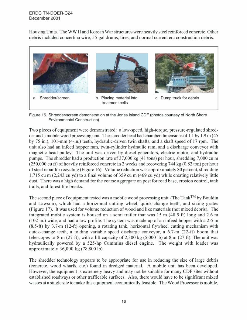
Two pieces of equipment were demonstrated: a low-speed, high-torque, pressure-regulated shred-der and amobile wood processing unit. The shredder head had chamber dimensions of 1.1 by 1.9m (45by 75 in.), 101-mm (4-in.) teeth, hydraulic-driven twin shafts, and a shaft speed of 17 rpm. Theunit also had an infeed hopper ram, twin-cylinder hydraulic ram, and a discharge conveyor withmagnetic head pulley. The unit was driven by diesel generators, electric motor, and hydraulicpumps. The shredder had a production rate of 37,000 kg (41 tons) per hour, shredding 7,000 cu m(250,000 cu ft) of heavily reinforced concrete in 2 weeks and recovering 744 kg (0.82 ton) per hourof steel rebar for recycling (Figure 16). Volume reduction was approximately 80 percent, shredding1,715 cu m (2,243 cu yd) to a final volume of 359 cu m (469 cu yd) while creating relatively littledust. There was a high demand for the coarse aggregate on post for road base, erosion control, tanktrails, and forest fire breaks.
The second piece of equipment tested was a mobile wood processing unit (The TankTM by Bouldinand Lawson), which had a horizontal cutting wheel, quick-change teeth, and sizing grates(Figure 17). It was used for volume reduction of wood and like materials (not mixed debris). Theintegrated mobile system is housed on a semi trailer that was 15 m (48.5 ft) long and 2.6 m(102 in.) wide, and had a low profile. The system was made up of an infeed hopper with a 2.6-m(8.5-ft) by 3.7-m (12-ft) opening, a rotating tank, horizontal flywheel cutting mechanism withquick-change teeth, a folding variable speed discharge conveyor, a 6.7-m (22-ft) boom thattelescopes to 8 m (27 ft), with a lift capacity of 2,300 kg (5,000 lb) at 8 m (27 ft). The unit washydraulically powered by a 525-hp Cummins diesel engine. The weight with loader wasapproximately 36,000 kg (78,800 lb).
The shredder technology appears to be appropriate for use in reducing the size of large debris(concrete, wood wharfs, etc.) found in dredged material. A mobile unit has been developed.However, the equipment is extremely heavy and may not be suitable for many CDF sites withoutestablished roadways or other trafficable surfaces. Also, there would have to be significant mixedwastes at a single site tomake this equipment economically feasible. TheWood Processor ismobile,
Figure 15. Shredder/screen demonstration at the Jones Island CDF (photos courtesy of North ShoreEnvironmental Construction)
a. Shredder/screen b. Placing material intotreatment cells
c. Dump truck for debris
ERDC TN-DOER-C24December 2001
16
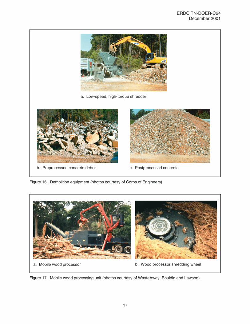
Figure 16. Demolition equipment (photos courtesy of Corps of Engineers)
a. Low-speed, high-torque shredder
b. Preprocessed concrete debris c. Postprocessed concrete
Figure 17. Mobile wood processing unit (photos courtesy of WasteAway, Bouldin and Lawson)
a. Mobile wood processor b. Wood processor shredding wheel
ERDC TN-DOER-C24December 2001
17

easily set up, and should be applicable for wood waste reduction at CDFs if there is a significantneed.
POCs: Wally Crow, Fort Campbell, and Deborah Curtin, Construction Engineering ResearchLaboratory, U.S. Army Engineer Research and Development Center, (217)398-5567.
SUMMARY: The useful life of a CDF can be extended by removing dredged material forapplication to beneficial uses. The composition of dredged sediments in CDFs reflects severalfactors, including the watershed in which dredging takes place, local land use activities, and methodof disposal with mechanical or hydraulic dredges. Mechanical dredges pick up relatively undis-turbed loads of sediment that can include debris, while trash may be present in both mechanicallyand hydraulically dredged sediments.
CDFmaterial processing plants usually consist of a series of units. A grizzly unit is commonly usedat the beginning of the processing train to separate large debris and trash, although a rake in a scowcould be used for this purpose. The use of other types of equipment in the processing train such astrommels, vibrating screens, or shredders depends on the composition of the dredged material, thechosen end use, and the presence of contaminants that may require remediation.
Examples are presented illustrating debris and trash removal during sand and gravel reclamation,topsoil production, and construction fill development. A variety of equipment and methods areavailable for reclamation of CDFs having dredged materials with diverse physical and chemicalcharacteristics and different end uses.
POINTS OFCONTACT: For additional information, contact Dr. Tommy E. Myers (601-634-3939,[email protected]), or the Program Manager of the Dredging Operations andEnvironmental Research Program, Dr. Robert M. Engler (601-634-3624, [email protected]). This technical note should be cited as follows:
Spaine, P. A., Thompson, D. W., Jones, L. W., and Myers, T. E. (2001). “Determiningrecovery potential of dredged material for beneficial use – Debris and trash removal,”DOER Technical Notes Collection (ERDC TN-DOER-C24), U.S. Army EngineerResearch and Development Center, Vicksburg, MS.www.wes.army.mil/el/dots/doer/
REFERENCES
Arthur D. Little, Inc. (1998). “Conceptual design and costing of two sediment processing configurations,” Final Report(Reference 35796) to U.S. Army Engineer Waterways Experiment Station, Vicksburg, MS.
Benner, B.R., Wu, C., and Zanko, L. M. (2001). Alternative technology for sediment remediation; DemonstrationPlant, Final Report, Coleraine Minerals Research Laboratory, University of Minnesota-Duluth, Natural ResourcesResearch Institute, Duluth, MN.
de Kreuk, M. K., de Kreuk, J. F., and van Muijen, H. (1998). “Higher separation efficiency for dredged material, sievesand and soil by using pulsating bed separation.” Technology 2000 Symposium: Grond Zeefxand en Baggerspecie,grondstof voor nuttig toepasbare producten, Amsterdam, 10 September 1998. Ministry of Environmental Affairs,The Netherlands.
ERDC TN-DOER-C24December 2001
18

Engler, R. M., Wright, T., Lee, C. R., and Dillon, T. M. (1988). “Corps of Engineers’ procedures and policies ondredging and dredged material disposal (The Federal Standard),” Environmental Effects of Dredging TechnicalNote EEDP-04-8, U.S. Army Engineer Waterways Experiment Station, Vicksburg, MS.
Graalum, S. J., Randall, R. E., and Edge, B. L. (1999). “Methodology for manufacturing topsoil using sediment dredgedfrom the Texas Gulf Intracoastal Waterway,” Journal of Marine Environmental Engineering 5, 121-158.
Headquarters, U.S. Army Corps of Engineers. (1983). “Dredging and dredged material disposal,” Engineer Manual1110-2-5025, Washington, DC.
Headquarters, U.S. Army Corps of Engineers. (1987a). “Beneficial uses of dredged material,” Engineer Manual1110-2-5026, Washington, DC.
Headquarters, U.S. Army Corps of Engineers. (1987b). “Confined disposal of dredged material,” Engineer Manual1110-2-5027, Washington, DC.
Herbich, J. B. (2000). Handbook of dredging engineering. 2nd ed., McGraw-Hill, New York.
Lee, C. R. (2000). “Implementation guidance for the control of undesirable vegetation on dredged material,” DOERTechnical Notes Collection (ERDC TN-DOER-C20), U.S. Army Engineer Research and Development Center,Vicksburg, MS. www.wes.army.mil/el/dots/doer/
Olin-Estes, T. J., and Palermo, M. R. (2000). “Determining recovery potential of dredged material for beneficial use– Site characterization: Prescriptive approach,” DOER Technical Notes Collection (ERDC TN-DOER-C14), U.S.Army Engineer Research and Development Center, Vicksburg, MS. www.wes.army.mil/el/dots/doer/
Olin, T. J., Bailey, S. E., Mann, M. A., Lutes, C. C., Seward, C. A., and Singer, C. F. (1999). “Physical separation (soilwashing) for volume: Reduction of contaminated soils and sediments processes and equipment,”EPA-905-R-99-006, U.S. Environmental Protection Agency, Great Lakes National Program Office, Chicago, IL.
Oweis, Issa. (1999). “Case study geotechnics of utilizing dredged sediments as structural fill.” Proceedings, NationalSymposium on Contaminated Sediments Coupling Risk Reduction with Sustainable Management and Reuse.Transportation Research Board, National Research Council, National Academy Press, Washington, DC, 19, 40-42.
TAMS Consultants, Inc. (2000). “Hudson River PCBs Reassessment RI/FS Phase 3 Report: Feasibility Study;Appendix H, Hudson River Debris,” prepared for U.S. Environmental Protection Agency, Region 2, and U.S. ArmyEngineer District, Kansas City.
U.S. Army Corps of Engineers/U.S. Environmental Protection Agency. (1992). “Evaluating environmental effects ofdredged material management alternatives — A technical framework,” EPA 842-B-92-008, U.S. EnvironmentalProtection Agency, Office of Water, Washington, DC.
U.S. Army Engineer District, Detroit. (1994). “Pilot-scale demonstration of solvent extraction for the treatment ofGrand Calument River sediments,” EPA905-R94-003, prepared for the U.S. Environmental Protection Agency,Great Lakes National Program Office, Chicago, IL.
Winfield, L. E., and Lee, C. R. (1999). “Dredged material characterization tests for beneficial use suitability,” DOERTechnical Notes Collection (TN DOER-C2), U.S. Army Engineer Research and Development Center, Vicksburg,MS. www.wes.army.mil/el/dots/doer/
NOTE: The contents of this technical note are not to be used for advertising, publication,or promotional purposes. Citation of trade names does not constitute an official endorse-ment or approval of the use of such products.
ERDC TN-DOER-C24December 2001
19