
design_and_construction_reference_manual
40
Design and Construction Reference Manual ReCon Series 50 Aesthetics You Want… …Performance You Need!
-
Upload
james-basbas -
Category
Documents
-
view
212 -
download
0
description
http://www.sheaconcrete.com/pdf/design_and_construction_reference_manual.pdf
Transcript of design_and_construction_reference_manual

Design and Construction Reference Manual
ReCon Series 50
Aesthetics You Want… …Performance You Need!

www.reconwalls.com

IntroductionAt ReCon, we are proud of our tradition of offering a product line that adds value for our customers, and for our wall design and wall contractor partners. Whether the ReCon application focuses on the scale and aesthetics of the ReCon Block, the durability of the wet-cast, air-entrained concrete, the considerable gravity wall heights that can be achieved, or the construction efficiencies associated with our product, it is our intention to solve site specific challenges and add value.The design of a ReCon segmental retaining wall may be fairly straightforward or it may be quite complex and involve a high degree of geotechnical and/or civil engineering expertise. At first glance, the steps involved in construction of a ReCon retaining wall appear relatively simple. In fact, they are; however, it is critical that these procedures are done properly if the wall is to last and perform as designed. This is due to the fact that the ReCon units themselves are often just a key
component in what is a more complex and inter-dependent composite earthen structure. A number of important variables must be analyzed before a proper wall design can be finalized. This manual is intended to
provide wall designers, wall installers and others with the information useful in the design, the construction and cost estimation of a ReCon retaining wall that will remain attractive and structurally stable for the duration of its intended design life.
Page 3

...............................................................................................................ReCon Series 50 Shapes Data 5...................................................................................................................................................................................Shapes 5
.................................................................................................................................................................................Textures 8...................................................................................................................................................................Le Sueur County Limestone 8
................................................................................................................................................................................North Shore Granite 8
................................................................................................................................................................................................Old World 8
......................................................................................................................................................................................................Rustic 8
..................................................................................................................................Design Parameters 9.......................................................................................................................................................................Wall Geometry 9
...................................................................................................................................................................Soils Information 9............................................................................................................................................................Unit Characteristics 11
.................................................................................................................................................................Water / Drainage 12..........................................................................................................................................................................Surcharges 13
.....................................................................................................................................................................Terraced Walls 14..........................................................................................................................................................Terraced Wall “2:1” General Rule 14
..................................................................................................................................Wall Construction 15..................................................................................................................................................................Site Preparation 15
...........................................................................................................................................................................Excavation 15...............................................................................................................................................Preparing the Leveling Pad 15
....................................................................................................................................................Base Course Installation 16...............................................................................................................................................Backfilling and Compaction 17...............................................................................................................................................Placing Additional Courses 17
.............................................................................................................................................................Geogrid Placement 18.......................................................................................................................................................................Curved Walls 19
.........................................................................................................................................Reinforcement Placement on Curved Walls 20
...............................................................................................................................................Outside 90 Degree Corners 21..................................................................................................................................................Inside 90 Degree Corners 21
..................................................................................................................................Double Outside 90 Degree Corners 22...........................................................................................................................Outside 90 Degree Corner to Abutment 22
.......................................................................................................................................................Top of Wall Treatments 23...................................................................................................................................................................................ReCon Top Units 23
..............................................................................................................................................................................................Cap Units 24
...............................................................................................................................................................................Full-High Cap Units 25
.....................................................................................................................................................................................................Steps 25
.....................................................................................................................................................Railings and Guardrails 26..........................................................................................................................................................Staining and Sealing 26
..............................................................................................ReCon “Series 50” Guide Specification 27..........................................................................................................Increasing Gravity Wall Heights 32
.................................................................................................................Typical Gravity Wall Section 33..........................................................................................ReCon Series 50 Standard Design Charts 34
.......................................................................................................................................................................Gravity Walls 34..................................................................................................................................................Geogrid Reinforced Walls 35
.................................................................................................................................................Warranty 38
Table Of Contents
Page 4

ReCon Series 50 Shapes Data
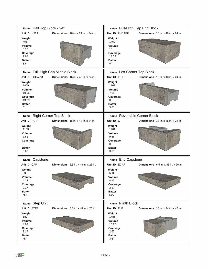
ShapesReCon Series 50 units are available in a large variety of shapes. These shapes are designed to
enhance the aesthetic appearance of a finished retaining wall. In addition, the large selection
provides for ease and simplicity in the installation process without adding undue complexity for
designers, installers and manufacturers alike.
The shapes shown are representative of the most common ReCon Series 50 block shapes.
Actual block shapes and texture options vary by region. Check with your local supplier to determine
availability.
Because ReCon Series 50 units are manufactured from wet-cast, air-entrained concrete, they lend
themselves to a varying degree of customization. Many existing shapes and face textures were
originally developed to accommodate the needs of an owner, designer or installer. If some unique
shape or texture is required it may be possible to develop products not already available. Given a
reasonable amount of time, ReCon manufacturers should be able to determine the viability and cost
estimate of such a request.
Page 5
Name Full Base Block - 24”
Unit ID FB24
Weight1457
Volume10.04
Coverage5.33
Batter3.6°
Dimensions 16 in. x 48 in. x 24 in.
Name Full Middle Block - 24”
Unit ID FM24
Weight1411
Volume9.73
Coverage5.33
Batter3.6°
Dimensions 16 in. x 48 in. x 24 in.
Name Three Quarter Block - 24”
Unit ID TQM24
Weight1037
Volume7.15
Coverage4
Batter3.6°
Dimensions 16 in. x 36 in. x 24 in.
Name Half Base Block - 24”
Unit ID HB24
Weight710
Volume4.90
Coverage2.67
Batter3.6°
Dimensions 16 in. x 24 in. x 24 in.
Name Half Block - 24”
Unit ID HM24
Weight662
Volume4.57
Coverage2.67
Batter3.6°
Dimensions 16 in. x 24 in. x 24 in.
Name Full Base Block - 39”
Unit ID FB39
Weight2276
Volume15.7
Coverage5.33
Batter3.6°
Dimensions 16 in. x 48 in. x 39 in.

Page 6
Name Full Middle Block - 39”
Unit ID FM39
Weight2201
Volume15.18
Coverage5.33
Batter3.6°
Dimensions 16 in. x 48 in. x 39 in.
Name Three Quarter Block - 39”
Unit ID TQM39
Weight1586
Volume10.94
Coverage4
Batter3.6°
Dimensions 16 in. x 36 in. x 39 in.
Name Half Block - 39”
Unit ID HM39
Weight967
Volume6.67
Coverage2.67
Batter3.6°
Dimensions 16 in. x 24 in. x 39 in.
Name Full Base Block - 45”
Unit ID FB45
Weight2550
Volume17.58
Coverage5.33
Batter3.6°
Dimensions 16 in. x 48 in. x 45 in.
Name Full Middle Block - 45”
Unit ID FM45
Weight2491
Volume17.18
Coverage5.33
Batter3.6°
Dimensions 16 in. x 48 in. x 45 in.
Name Half Block - 45”
Unit ID HM45
Weight1067
Volume7.36
Coverage2.67
Batter3.6°
Dimensions 16 in. x 24 in. x 45 in.
Name Full Base Block - 60”
Unit ID FB60
Weight3173
Volume21.88
Coverage5.33
Batter3.6°
Dimensions 16 in. x 48 in. x 60 in.
Name Full Middle Block - 60”
Unit ID FM60
Weight3115
Volume21.48
Coverage5.33
Batter3.6°
Dimensions 16 in. x 48 in. x 60 in.
Name Fitting Block - 24”
Unit ID FF24
Weight1215
Volume8.38
Coverage5.33
Batter3.6°
Dimensions 16 in. x 48 in. x 24 in.
Name Full Top Block - 24”
Unit ID T24
Weight971
Volume6.7
Coverage5.33
Batter3.6°
Dimensions 16 in. x 48 in. x 24 in.
Page 7
Name Half Top Block - 24”
Unit ID HT24
Weight458
Volume3.16
Coverage2.67
Batter3.6°
Dimensions 16 in. x 24 in. x 24 in.
Name Full-High Cap End Block
Unit ID FHCAPE
Weight1450
Volume10
Coverage13.33
Batter0°
Dimensions 16 in. x 48 in. x 24 in.
Name Full-High Cap Middle Block
Unit ID FHCAPM
Weight1459
Volume10.06
Coverage13.33
Batter0°
Dimensions 16 in. x 48 in. x 24 in.
Name Left Corner Top Block
Unit ID LCT
Weight1103
Volume7.61
Coverage8
Batter3.6°
Dimensions 16 in. x 48 in. x 24 in.
Name Right Corner Top Block
Unit ID RCT
Weight1103
Volume7.61
Coverage8
Batter3.6°
Dimensions 16 in. x 48 in. x 24 in.
Name Reversible Corner Block
Unit ID C
Weight1401
Volume9.66
Coverage8
Batter3.6°
Dimensions 16 in. x 48 in. x 24 in.
Name Capstone
Unit ID CAP
Weight600
Volume4.13
Coverage2.17
BatterN/A
Dimensions 6.5 in. x 48 in. x 26 in.
Name End Capstone
Unit ID ECAP
Weight600
Volume4.13
Coverage2.17
BatterN/A
Dimensions 6.5 in. x 48 in. x 26 in.
Name Step Unit
Unit ID STEP
Weight680
Volume4.69
Coverage2.17
BatterN/A
Dimensions 6.5 in. x 48 in. x 26 in.
Name Plinth Block
Unit ID PLB
Weight1486
Volume10.25
Coverage2.67
Batter3.6°
Dimensions 16 in. x 24 in. x 47 in.

TexturesReCon currently offers its licensed manufacturers a choice of four types of face textures. Most
producers choose one of these textures as their standard and elect to maintain a working inventory of
that texture. Other textures may still be available as a special order. As with most special orders,
additional costs may be involved and sufficient time should be allowed for setup and production.
Check with the ReCon licensed manufacturer in your market to determine what textures are
available.
1) Le Sueur County LimestoneThis texture offers the look of a
broken and weathered limestone.
This texture lends itself well to
accent staining. When certain stain
colors are used, Le Sueur County
Limestone can also take on the
appearance of a weathered sandstone material.
2) North Shore GraniteGranite may be the most universally
recognized natural stone on earth.
While its coloration varies widely, the
texture of an unprocessed granite is
somewhat consistent in the way it
fractures due to its composition and
density. Stained or unstained, the appearance of North Shore Granite
can be nearly indistinguishable from weathered natural stone.
3) Old WorldReCon’s Old World texture was
originally developed as a
“special order” to match the
appearance of the popular cut
stone building materials used in
the late 1800’s and early 1900’s.
Many different types of stone were used in this
manner and the Old World texture can emulate
most of them depending on the stains that are used. The face also lends itself to further
processing, such as sandblasting or using a retarder to expose aggregates.
4) RusticThe Rustic Stone texture captures
the authenticity of a natural
weathered cut stone that has been
stacked in eight-inch coursing. The
length of the individual stones varies
from as little as eight inches to as
much as twenty-six inches, resulting in a natural random pattern.
Page 8

Design Parameters
Wall GeometryWhen planning a ReCon retaining wall, the
most logical place to start is the wall location
and where it resides with reference to the
project site and topography. For most
commercial projects this information is usually
found on the site-grading plan. A great deal of
the information necessary to properly design
a ReCon retaining wall can be found there. In
addition to the calculation of wall heights and
lengths, designers study this plan in order to
gather information about adjacent structures,
surcharges, site access, property lines, utility
locations and site drainage. All of these
factors influence the final design and
construction of a ReCon retaining wall.
For projects that don’t have a formal site-grading plan, wall designers still need this information to be
gathered, even if perhaps in a less formal way. Regardless of the source, access to this information
is critical to proper design; determination of unit types; and the formulation of accurate unit quantities
and cost estimates.
Soils InformationSegmental retaining walls (SRWs) are by definition a soil structure with a modular and mortarless
aesthetic facing. In some cases, the facing itself can provide sufficient resistance to natural soil
forces and potential wall movement. When this is true, the wall is commonly referred to as a “gravity
wall”. The ability to construct taller gravity walls is one of the key advantages of the ReCon Series 50 retaining wall system. How and why ReCon can achieve these heights will be addressed
in the appropriate sections of this manual. When the mass, footprint and other properties of the
facing units are insufficient to restrain movement of a given segmental retaining wall structure, soil
reinforcement is introduced to the soil mass behind the wall to increase stability. These composite
structures are commonly referred to as reinforced segmental retaining walls or “MSE walls”, which is
an acronym for “mechanically stabilized earth”.
Page 9
Gravity Wall
Retained SoilZone
Reinforced SoilZone
Reinforced Wall
Leveling Pad
Drain Tile
Impervious Soil Layer
Embedded Reinforcement Layers
Drainage Aggregate
Zone

If soil is a main component of an SRW structure, then it is necessary for wall designers to know and
understand the properties of these soils. Soils come in a “near infinite” number of types and
compositions. In commercial projects, SRW wall designers often learn about the properties of the
soils on a project site from a Soil Boring Log. Knowledgeable civil or geotechnical engineers evaluate
this information in order to predict a completed SRW’s performance. In the absence of detailed soils
information, wall designers must make some assumptions about the soil properties in order to
proceed. When assumptions about soils must be made, they are usually, and should be,
conservative in order to preserve the necessary safety factors for wall integrity. There are some soils
that should never be used in a SRW. A detailed discussion of all soil types and properties is beyond
the scope of this manual. The determination of particular soil suitability for use in a SRW rightfully
belongs within the realm of a trained and experienced civil or geotechnical engineer.
The soils that are of critical interest to a wall designer are categorized into five basic “zones” with
respect to their location in and around the finished wall.
1) The leveling pad is not really a zone, per se, but is an integral and necessary part of a well-designed, well-built SRW. It consists of a material similar to that of road gravel that allows for drainage, but also contains enough fines to allow it to compact well and “hold its shape”. Class 5, ¾” minus, crush & run and road base are some of the regional names given to this type of material. The dimensions for the leveling pad vary and are discussed elsewhere in this manual.
2) The drainage zone is typically an imported, well-draining crushed rock material that fills the voids in and around the facing units to a minimum depth of one foot behind the back of the facing. This zone functions as a “French drain” to transport water otherwise trapped behind the finished wall to a drainage collection or dispersal area. This material should be relatively free of fine-grained materials and also should be “self-compacting”. This eliminates the need to operate compaction equipment in close proximity to the back of the wall facing.
3) The foundation soil zone comprises the area immediately beneath the facing components and drainage zone and is responsible for providing adequate support for the weight of the retained wall above. If the wall is a reinforced SRW, the foundation zone also extends beneath and behind the wall to a distance roughly equal to the depth of the embedded soil reinforcement.
4) The reinforced soil zone only exists in MSE walls and extends from the back of the drainage zone to an embedded depth equal to the back of the geosynthetic soil reinforcement. This soil may have its origin on-site or it can be a “select fill” material brought on-site from elsewhere. The properties of this material strongly influence the performance characteristics of the reinforced soil mass and, as such, have a significant effect on the strength, length and quantity of soil reinforcement in the finished wall. Ultimately, the design of a finished soil-reinforced wall is greatly affected by the material confined within this soil zone.
5) The retained soil zone is the material either behind the reinforced soil zone, in the case of a soil-reinforced SRW, or behind the drainage zone in a gravity retaining wall. Soil characteristics within this zone also have a significant effect on the design of the finished wall in the same way that the reinforced soil zone does.
Page 10
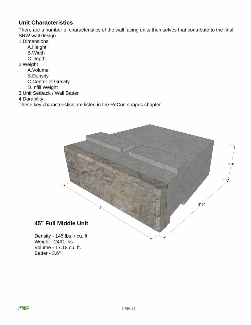
Unit CharacteristicsThere are a number of characteristics of the wall facing units themselves that contribute to the final SRW wall design.1.Dimensions
A.HeightB.WidthC.Depth
2.WeightA.VolumeB.DensityC.Center of GravityD.Infill Weight
3.Unit Setback / Wall Batter4.DurabilityThese key characteristics are listed in the ReCon shapes chapter.
Page 11
45” Full Middle Unit
Density - 145 lbs. / cu. ft.Weight - 2491 lbs.Volume - 17.18 cu. ft.Batter - 3.6°
Water / DrainageMost problems associated with SRWs can be traced back, directly or indirectly, to water. The
presence of water, whether or not anticipated, affects soil mechanics and places extra strain on a
finished wall. Water trapped behind a wall greatly increases retained pressures. A high water table
can weaken foundation soils to the point where they are unable to continue to support the wall.
Moving water over the top or along the bottom of a finished wall can erode away the soil to the point
where the wall becomes unstable and must be rebuilt. Finally, drainage must be considered during
the construction period as well as when the wall and final grading is completed. Water “traffic” on an
unfinished project site can be entirely different than what is designed for and intended on the
completed project. In short, the presence of water accentuates weaknesses in wall design and/or
construction. As such, care must be taken to avoid these water issues when designing and installing
a ReCon “Series 50” retaining wall.
By the same token, ReCon “Series 50” units are an excellent choice for the unique challenges that
water applications present. The durability, mass, footprint and specific gravity of a “Series 50” wall
enables designers to comfortably tackle these applications.
Shoreline or seawall retaining wall applications are unique and should be treated as such. The
design for these applications can vary significantly. Consult a qualified wall design engineer for these
situations and make sure to check all governing code requirements.
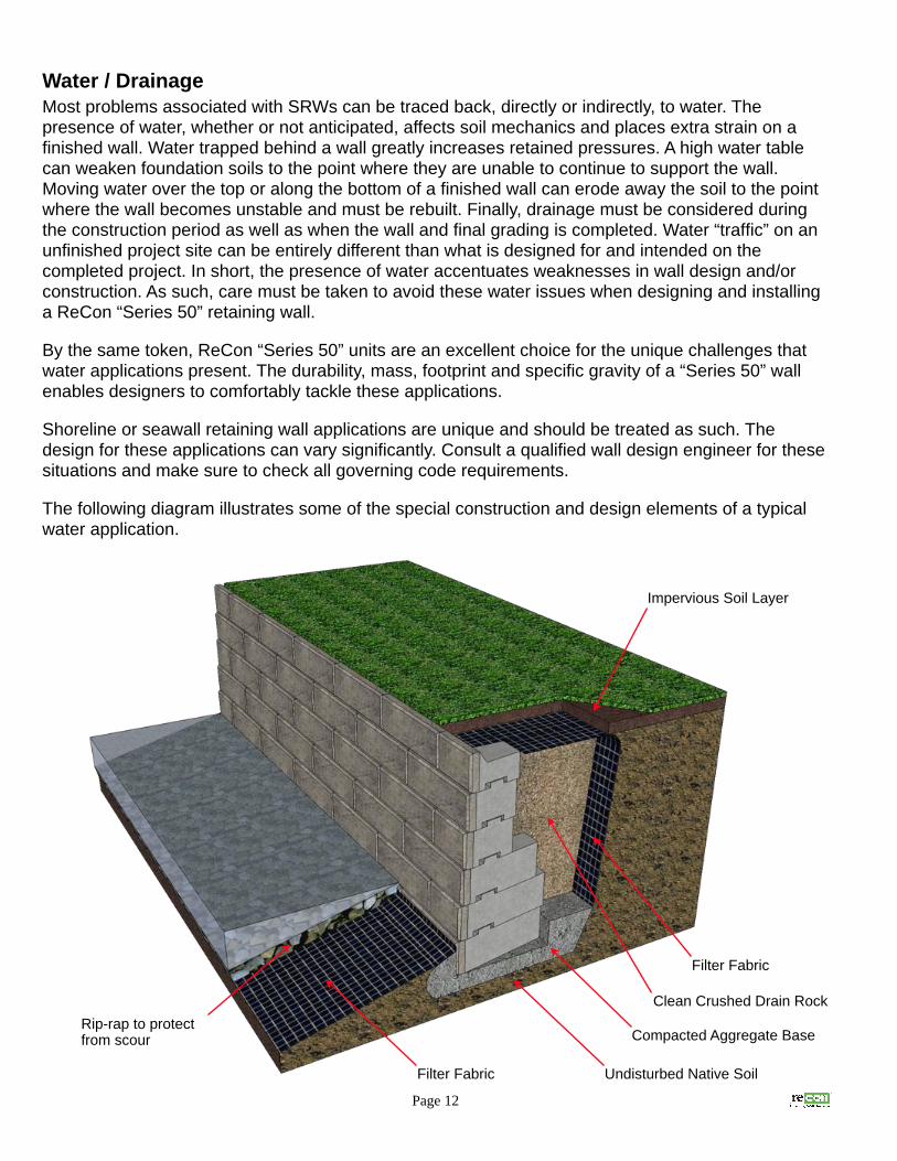
The following diagram illustrates some of the special construction and design elements of a typical
water application.
Page 12
Impervious Soil Layer
Filter Fabric
Clean Crushed Drain Rock
Compacted Aggregate Base
Undisturbed Native SoilFilter Fabric
Rip-rap to protect from scour

SurchargesWhen a SRW is exposed to additional loads, whether permanent or temporary, the overall wall
design is affected. Usually, when a structure, building, roadway or top slope is within twice the height
of the SRW wall face, its impact on the stability of the wall must be evaluated. This is only a general
rule based on the most common soil types. Wall design engineers must consider many other factors
which may adjust this proximity formula.
Surcharges may stabilize or destabilize a ReCon wall, depending on their type and / or relative
proximity to the wall.
By definition, surcharges are usually classified as a “live load” or “dead load”. A live load is generally
temporary in nature. An example might be a fully loaded semi truck traveling along a roadway within
close proximity to the finished SRW. Because it is by definition temporary, any stabilizing contribution
of a live-load surcharge is usually ignored. Ultimately, this results in a more conservative design with
an improvement in the overall safety factors for certain aspects of the wall design.
A dead load, by contrast, is intended to be permanent. Although it will increase stresses on the wall
depending on its type and proximity to the wall, it can also contribute to certain aspects of wall
stability. Examples of a dead load could be a slope above the wall that adds the extra weight of the
soil mass and must be accounted for in the wall design; or it may be a building exerting additional
weight through its foundation or footing. Another common type of dead load found on SRW sites
results from wall terracing. When a second (or third, etc.) SRW is built above another it needs to be
evaluated to see if it is imposing additional stresses on the wall (or walls) beneath it.
Page 13

Terraced WallsTerraced walls are a common feature in retaining wall applications. From an engineering standpoint,
these walls must be treated as a single composite structure if their proximity, in conjunction with other
site and soil parameters, is such that an upper wall places additional load or stress on the wall (or
walls) below.
Most terraced walls may be considered independent of each other if they meet the requirements of
the following rule of thumb.
Terraced Wall “2:1” General Rule“Terraced walls may generally be considered independent of each other if… 1) the height of the upper wall is less than or equal to the height of the lower wall and… 2) the distance between the two walls is at least twice the height of the lower wall.”
This general rule may not apply if soils are very poor, if toe or crest slopes are involved, or if there are
additional surcharges present.
Terraced walls that do not meet the “2:1” rule usually require additional mass and / or soil
reinforcement incorporated into the lower wall design in order to resist the additional stress incurred
from the upper wall or walls.
Page 14
13’ 4”
10’ 8”
>= 26’ 8”
Terraced Wall Example

Wall ConstructionThe following procedures comply with the generally accepted industry standards for the installation of
segmental retaining walls with special attention given to the unique features of the ReCon “Series 50”
product line. Every attempt should be made to follow these procedures as closely as possible unless
the project specifications, drawings or the final engineered wall design directs otherwise.
Site PreparationBefore beginning work, contractors should make
sure that they have thoroughly studied the project
specifications, the final engineered drawings for
the wall and complied with all the requirements
for product submittals. Contractors should also
have a clear understanding of their scope of work
and their responsibilities that may be covered
elsewhere in the project specifications and are
not in the actual wall construction section.
For projects that do not have a formal set of
plans and specifications but do have a “signed
and stamped” final engineered wall plan, the
contractor should refer to these procedures
whenever a topic is not specifically covered in the
final engineered plan.
ExcavationThe contractor should carefully excavate the wall
construction area to the lines and grades shown on
the construction drawings. Exercise caution to
keep the soil undisturbed in areas that will not need
modification during wall construction. Be sure to
identify above and below ground utilities including
power lines, communication lines, sewer and
drainage structures, etc.
Preparing the Leveling PadExcavate a trench to a minimum thickness of 6
inches and to a width that extends a minimum of
6 inches in front and behind the actual location of
the base units along their designated placement.
If the wall layout requires either inside or outside
radius curves, it is a good idea to increase the
width of the leveling pad to accommodate
adjustment during wall alignment. For all but
straight walls where the bottom elevation doesn’t Page 15

change along the entire length of the wall, stakes should be driven to the proper height as
determined by a transit to indicate the proper bottom elevation of the wall. These stakes should also
show where base step-ups are located. Bear in mind that each step-up causes the leveling pad
location to step back by one inch due to the integral setback of ReCon “Series 50” units.
Fill the trench and any over-excavated areas with the specified base material. Unless specified
otherwise, this material should generally consist of a well-draining material that also contains enough
fines that the leveling pad will hold its shape after compaction. Depending on the region, this material
may be referred to as road base, ¾” minus, crush and run or Class 5. Fully compact the base
material and add or remove material as necessary to keep the leveling pad as close to the final level
grade as possible. Where step-ups are located, base material should taper up at roughly a 45° angle.
At times a concrete leveling pad may be required or desirable in lieu of a compacted granular base
material. Unless the leveling pad is designed as a true “footing” and extends below frost depth, the
concrete should not contain steel reinforcing and should consist of a relatively weak mix capable of
breaking up under frost pressures. This allows for resettlement as the frost dissipates. Also, when
using a concrete leveling pad take extra care to keep the pad level and any step-ups at their proper
height to avoid difficulty in maintaining height tolerances.
Base Course InstallationThe first (base) course of a ReCon wall requires the use of a Base Block. This unit does not have the
special groove on the bottom. This makes for easier leveling of the base course and also provides
greater shear resistance at the interface between the leveling pad and ReCon base block.
Walls should generally be built starting at the lowest point in the wall. Make sure to properly place the
edge of the first unit at an even 2 foot increment from any fixed wall features such as a 90° corner, a
control joint or building structure. This helps to avoid unnecessary cutting or trimming of the ReCon
units and improves wall aesthetics.
Depending on the type of material used for the leveling pad and how level the pad is to start with,
base course leveling may be easier if the leveling pad is topped and screed with up to ½” of clean
sand. On long straight sections of wall, it may be helpful to set units with a canter or tip-back of up to
½”. This increases the ability to maintain a positive wall batter and minimize rotation during soil
compaction when robust compaction equipment is used.
As base units are laid, ensure that the units are in
full contact with the leveling pad and check to
ascertain that the units are level both front-to-
back and left-to-right. Use a jig if necessary to
maintain a consistent leveling plane from unit-to-
unit. Lay units end-to-end and avoid gaps
between units. The use of a string line will help
ensure proper wall alignment along straight
sections of wall. After the base units have been
placed and before compacting the backfill
material behind the wall, compaction to the
specified embedment depth should be done in
front of the wall.
Page 16

Backfilling and CompactionWhen all the units comprising a section of wall at a
single elevation have been placed, aligned and leveled,
fill the gaps between the units with a clean crushed rock
material at least ½” – ¾” in size. Use this same material
behind the back of the block to a depth of at least 1’ or
as otherwise indicated in the final engineered drawings.
This material serves as a “French drain” to relieve water
build-up and also, because it is self-compacting, it
relieves installers from having to operate compaction
equipment close to the back of the units.
At times, a filter fabric may be specified behind the
drainage aggregate material. This helps keep the
drainage zone clean and free from sedimentation. If present, wrap the fabric forward over the
drainage aggregate as the other backfill material is placed.
When drain tile is used, it should be located as shown
in the plans or drawings. Generally, the drain tile runs
along the back of the wall and is at the bottom of the
drainage aggregate zone at an elevation at or above the
bottom finished grade level. Drain tile should “daylight”
at least every 50’ along the length as well as at every
low point in the wall or as otherwise specified.
Place the specified backfill material and thoroughly
compact material in 8” lifts. Backfill material should be
compacted to 95% of standard proctor. Improper or inadequate compaction is a primary source of contractor-caused wall failures. Close attention
should be paid to changes in consistency and moisture
content of all backfill material. Use the proper type of compaction equipment. Sandy or gravelly
materials respond best to plate compaction equipment and clayey materials usually should be
“kneaded” by using a hand-operated “jumping jack” or “sheep’s foot “. Heavy-duty compaction
equipment should be kept a minimum of 5’ from the back of the ReCon Wall to avoid wall rotation.
Placing Additional CoursesPrior to placing successive courses, sweep and keep
clean any backfill material from the top of the ReCon
units and make sure that all voids are filled with the
proper drainage material. Place the next course in a
running bond pattern or as otherwise shown on the
engineer’s detailed wall elevation plan. Set the upper
unit and slide it forward until its bottom “groove” is in
full contact with the bottom unit’s “tongue”. Check and
adjust level at every course elevation. If shimming is
required, use a material such as an asphalt shingle and
cover as much of the “low” surface area as possible to
achieve the desired result.
Page 17

Geogrid PlacementWhen a geosynthetic reinforcement (geogrid) is required, use only the type (or types) specified. Also,
make sure the reinforcement is cut to the proper lengths as indicated on the final engineered plan.
Most geogrid types are “uni-axial” and must be laid perpendicular to the wall face. Check the
manufacturer’s data to insure proper orientation. The geogrid should be laid on the top of the block
as near to the front face as possible and extend back over a compacted, level backfill to the length
required. Sandwich the reinforcement under the next course of
ReCon “Series 50” units to anchor in-place. Pull
the grid taut to remove slack or
wrinkles. Stake the back of the
geogrid prior to placing backfill
material to maintain tension. When
placing backfill over a layer of geogrid,
start just behind the drainage
aggregate and fill towards
the back of the
geogrid. Avoid
operating backfill
equipment directly on
the tensioned geogrid
as much as possible. A
minimum of 6” of backfill
should be placed over the grid
prior to the operation of any
tracked equipment. Avoid sharp
turning and sudden braking with all
types of equipment to avoid displacing,
wrinkling or damaging the geogrid
reinforcement.
Page 18
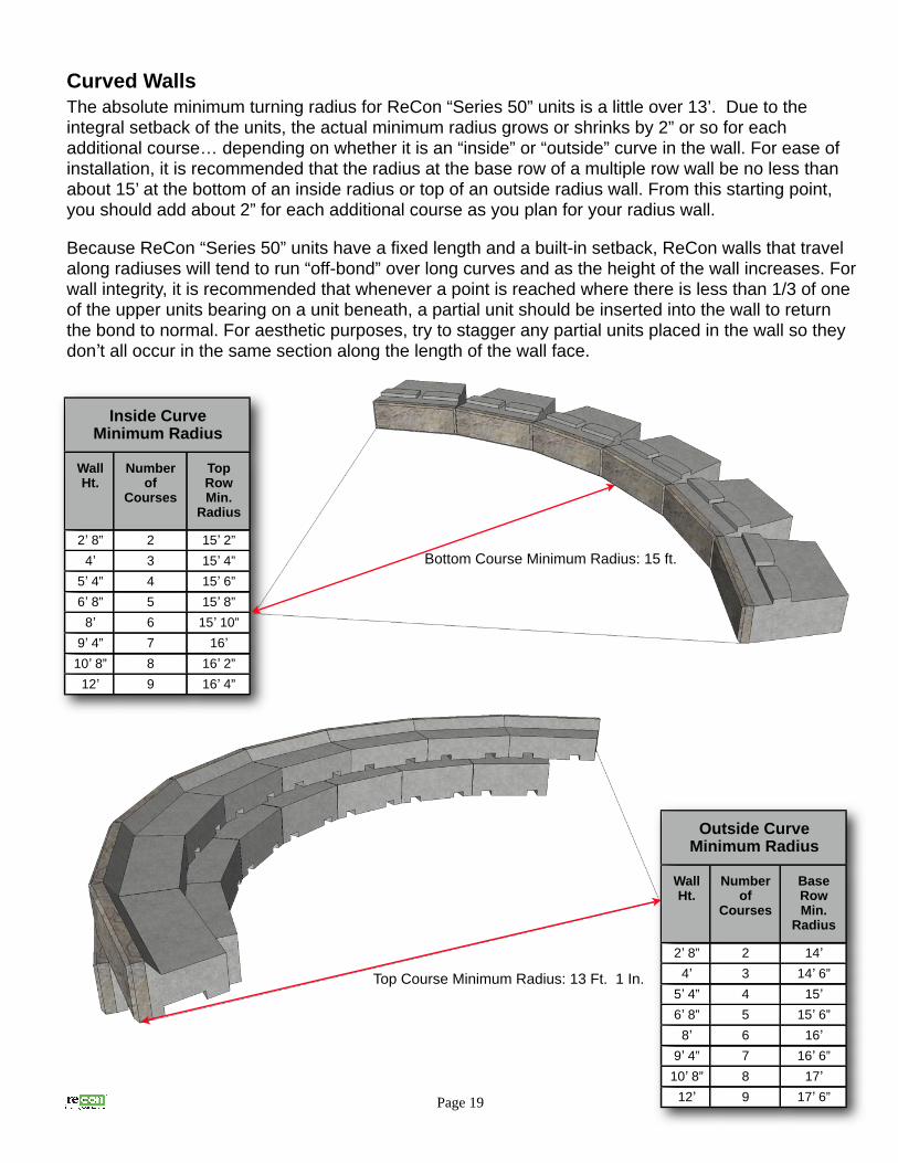
Curved WallsThe absolute minimum turning radius for ReCon “Series 50” units is a little over 13’. Due to the integral setback of the units, the actual minimum radius grows or shrinks by 2” or so for each additional course… depending on whether it is an “inside” or “outside” curve in the wall. For ease of installation, it is recommended that the radius at the base row of a multiple row wall be no less than about 15’ at the bottom of an inside radius or top of an outside radius wall. From this starting point, you should add about 2” for each additional course as you plan for your radius wall.
Because ReCon “Series 50” units have a fixed length and a built-in setback, ReCon walls that travel
along radiuses will tend to run “off-bond” over long curves and as the height of the wall increases. For
wall integrity, it is recommended that whenever a point is reached where there is less than 1/3 of one
of the upper units bearing on a unit beneath, a partial unit should be inserted into the wall to return
the bond to normal. For aesthetic purposes, try to stagger any partial units placed in the wall so they
don’t all occur in the same section along the length of the wall face.
Page 19
Inside Curve Minimum Radius
Wall Ht.
Number of
Courses
Top Row Min.
Radius
2’ 8” 2 15’ 2”
4’ 3 15’ 4”
5’ 4” 4 15’ 6”
6’ 8” 5 15’ 8”
8’ 6 15’ 10”
9’ 4” 7 16’10’ 8” 8 16’ 2”
12’ 9 16’ 4”
Bottom Course Minimum Radius: 15 ft.
Outside Curve Minimum Radius
Wall Ht.
Number of
Courses
Base Row Min.
Radius
2’ 8” 2 14’4’ 3 14’ 6”
5’ 4” 4 15’6’ 8” 5 15’ 6”
8’ 6 16’9’ 4” 7 16’ 6”
10’ 8” 8 17’12’ 9 17’ 6”
Top Course Minimum Radius: 13 Ft. 1 In.

Reinforcement Placement on Curved WallsMost accepted design methodologies stipulate that the reinforcement shall be continuous along the
length of the wall at both the front and rear of the reinforced soil zone. Geogrid layers should not
overlap unless there is compacted soil separating the individual layers. In addition, the natural
rectangular sections of geogrid should never be cut to form a wedge shape.
Rectangular reinforcement sections will naturally overlap in a pie-shaped fashion at either the front or
the back of the reinforced zone depending on whether the curve is “inside” or “outside”. The figures
show how reinforcement is laid out in this situation. All of the pie-shaped overlap areas should be
separated by at least 3” of backfill.
Page 20
- Overlay additional sections of geogrid so that the back of all pie-shaped gaps are covered.
- Place 3” fill between overlapping layers.
Place 3" of fill betweenoverlapping geogrid layers.

Outside 90 Degree CornersWhen building a wall with an Outside 90 Degree Corner, it is recommended that construction start at the corner and work away from this point in both directions. Unless one of the walls going away from the 90° corner runs into another corner or abutment, no block should need to be cut. One standard corner block will be used at the corner on each course, alternating the long and short returns. The corner blocks should be glued at the corner where they overlap with a high-quality, exterior-grade concrete adhesive.
Inside 90 Degree CornersWhen building a wall with an Inside 90 Degree Corner, it is recommended that once the base row is laid to the location of the inside corner, subsequent courses should begin at the corner and be laid outward from there. This avoids unnecessary trimming due to the built-in 1” setback. On taller walls, the “running bond joint” will slide off center by 2” for every other row. This does not affect the structural integrity of the wall. One standard corner block will be used at the corner on each row of the wall. The corner blocks will overlap each other at the corner, coming together in an alternating long/short fashion. The corner blocks should be glued at the corner where they overlap with a concrete adhesive.
Page 21
Right Corner Top
Top Course
Even Course
Odd Course
Full Corner Block
Full Corner Block
Remove part of front face of top unit
Corner Units
Top Course
Even Course
Bottom (odd) Course
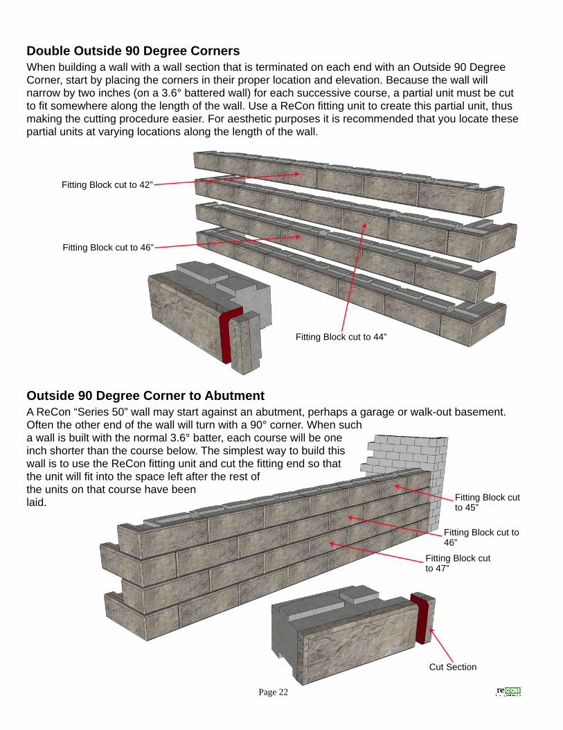
Double Outside 90 Degree CornersWhen building a wall with a wall section that is terminated on each end with an Outside 90 Degree Corner, start by placing the corners in their proper location and elevation. Because the wall will narrow by two inches (on a 3.6° battered wall) for each successive course, a partial unit must be cut to fit somewhere along the length of the wall. Use a ReCon fitting unit to create this partial unit, thus making the cutting procedure easier. For aesthetic purposes it is recommended that you locate these partial units at varying locations along the length of the wall.
Outside 90 Degree Corner to AbutmentA ReCon “Series 50” wall may start against an abutment, perhaps a garage or walk-out basement. Often the other end of the wall will turn with a 90° corner. When such a wall is built with the normal 3.6° batter, each course will be one inch shorter than the course below. The simplest way to build this wall is to use the ReCon fitting unit and cut the fitting end so that the unit will fit into the space left after the rest of the units on that course have been laid.
Page 22
Fitting Block cut to 42”
Fitting Block cut to 46”
Fitting Block cut to 44”
Cut Section
Fitting Block cut to 45”
Fitting Block cut to 46”
Fitting Block cut to 47”

Top of Wall TreatmentsReCon Top Units
The tops of ReCon walls are usually either capped using ReCon “Series 50” cap units or finished with
top block units. Other treatments typically involve special construction, such as forming and pouring a
concrete parapet or attaching specialty, precast components.
Capping a wall is a fairly straightforward process. However, radius walls require cutting of the cap
units to avoid creating triangular wedges at the front or back of the wall, depending on whether it is
an “inside” or “outside” radius.
Using the ReCon “Series 50” top blocks to finish off a wall provides the ability to fill units with a
landscape rock or plant material to within 4” of the wall face. When stepping up or down at the top of
a wall using top blocks, the “top corner block” is used to make this transition. A top corner block can
be laid with either the 2’ or the 4’ face as the return side. Usually the wall layout elevation plan
prepared by the design engineer will indicate the proper unit location or type. In the absence of such
a plan, the left and right top corner units designate which side the 2’ return dimension is located as
you face the finished wall. This is referred to as “standard” placement.
If it is desired that the 4’ face returns back into the retained soil, then a left corner top block will
actually return (with respect to the wall face) on its right side and visa-versa for a right corner top
block. This is referred to as “alternate” placement.
When the standard
placement (4’ face, 2’ return) is used,
it will be
necessary for
block stability to
add a concrete
shim beneath the
portion of the top
corner block that
bears on part of
another top block
located beneath.
This shim is usually
made or cut, if necessary,
from a standard
concrete masonry
unit (CMU). Gluing
this shim in place
will resist movement
during the backfilling
process.
This procedure will not be necessary when top corner blocks are placed in
the wall with the 2’ face outward and the 4’ face used as the return. In this
scenario, the block should be resting entirely on ½ of a full unit. In order for the unit to
lay flat and level, a section (approx. 7”) of the tongue on the lower unit must be removed.
Page 23
Standard Placement
LH Top Corner Unit
RH Top Corner Unit
Top Unit w/ 7.5” CMU shim

Cap UnitsReCon Cap Units are rectangular in shape and are available in two shapes, a regular cap that has a
groove along the entire bottom of the unit and an end cap where the groove terminates 4” from one
end to provide a finished appearance on one end. These caps are placed with a scissors clamp and
are intended primarily for straight walls. If cap units are to be used atop curved wall sections they will
need to be cut to provide a continuous finished appearance.
Page 24
Alternate Placement
24” Top Units
LH Top Corner Unit
RH Top Corner Unit
Section of tongue removed
Middle Units
Base Units24” Top Units
End Cap Units
Half End Cap Units
Regular Cap Unit
Remove 4” section of tongue to accommodate End Cap Units

Full-High Cap UnitsReCon Full-High Cap Units can be used when some freeboard above top grade is expected at the
top of a wall. This solution can be useful when the wall involves numerous step-ups at the top of the
finished wall and a finished appearance is desired for all exposed block above grade.
StepsThere are numerous configurations that incorporate steps into a retaining wall. The most common is
where the steps begin at the base of the wall and go up through the wall to the top grade. Other step
configurations, such as steps protruding from a wall or running parallel up along the wall face can
also be designed and would be built using the same general procedures.
Page 25
Back Side of Wall
Full High Cap End UnitsFull High Cap Middle Units
Base Units
Middle Units
Remove 1" from backof tongue to allow unitsto be stacked without batter.
Step Units are double-stackedfor increased stability andresistance to settlement.
Walls Adjacent to Stepsare Stacked Vertical (0° Batter).
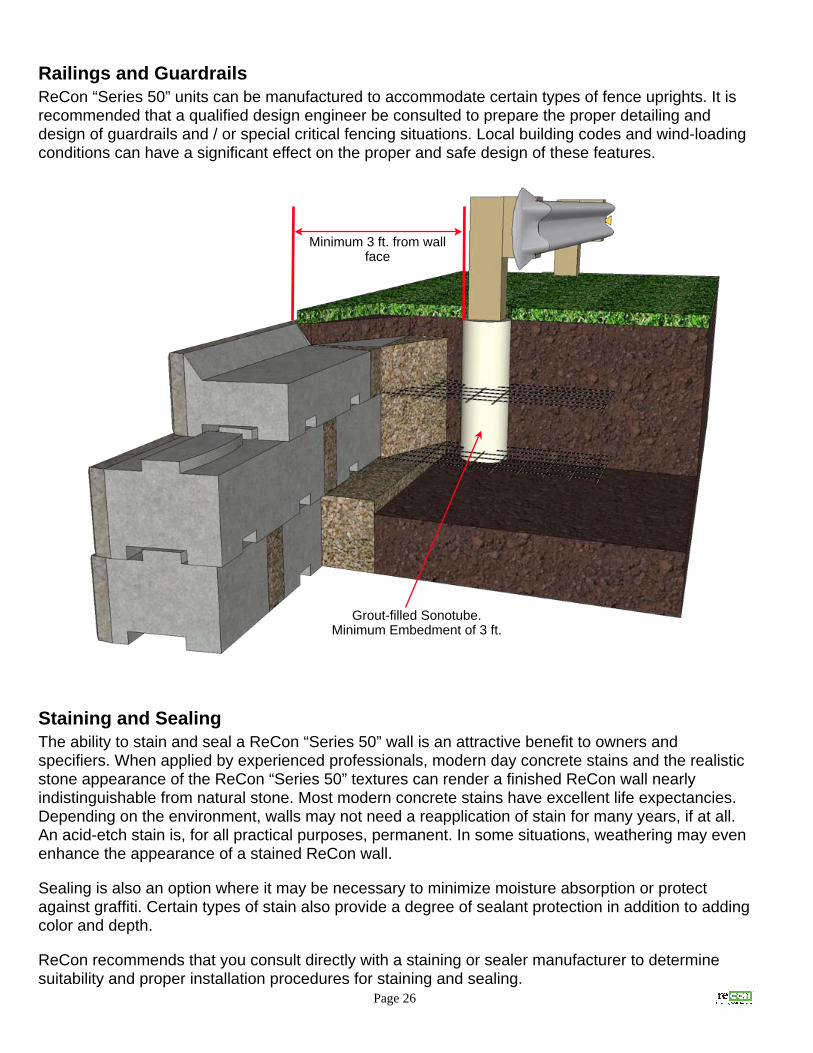
Railings and GuardrailsReCon “Series 50” units can be manufactured to accommodate certain types of fence uprights. It is
recommended that a qualified design engineer be consulted to prepare the proper detailing and
design of guardrails and / or special critical fencing situations. Local building codes and wind-loading
conditions can have a significant effect on the proper and safe design of these features.
Staining and Sealing The ability to stain and seal a ReCon “Series 50” wall is an attractive benefit to owners and
specifiers. When applied by experienced professionals, modern day concrete stains and the realistic
stone appearance of the ReCon “Series 50” textures can render a finished ReCon wall nearly
indistinguishable from natural stone. Most modern concrete stains have excellent life expectancies.
Depending on the environment, walls may not need a reapplication of stain for many years, if at all.
An acid-etch stain is, for all practical purposes, permanent. In some situations, weathering may even
enhance the appearance of a stained ReCon wall.
Sealing is also an option where it may be necessary to minimize moisture absorption or protect
against graffiti. Certain types of stain also provide a degree of sealant protection in addition to adding
color and depth.
ReCon recommends that you consult directly with a staining or sealer manufacturer to determine
suitability and proper installation procedures for staining and sealing.
Page 26
Minimum 3 ft. from wall face
Grout-filled Sonotube. Minimum Embedment of 3 ft.

ReCon “Series 50” Guide SpecificationNote: This guide specification should not be included entirely “as-is”. Specification writers must edit areas in red which may or may not be relevant to a specific project or where mutually exclusive choices are referenced.
SECTION 323223SEGMENTAL RETAINING WALL
PART 1 GENERAL1.
1.1. SUMMARYA. Section Includes: Furnishing materials and labor required for the design and construction of a ReCon “Series 50” concrete
segmental retaining wall.B. Related Sections:
1. Section 312000 Earth Moving2. Section 099313.13 Exterior Staining3. Section 099723 Concrete and Masonry Coatings4. Section 099623 Graffiti-Resistant Coatings
1.2. REFERENCESA. Concrete Segmental Retaining Wall Units - American Society for Testing and Materials (ASTM)
1. ASTM C-1372 Specification for Segmental Retaining Wall Units (Sections 7, 8 & 9)B. Drain Pipe - American Society for Testing and Materials (ASTM):
1. ASTM D-3034 Specifications for Polyvinyl Chloride Pipe (PVC)2. ASTM D-1248 Specifications for Corrugated Plastic Pipe
C. Geo-grid Reinforcements - Geosynthetic Research Institute (GRI) and American Society for Testing and Materials (ASTM):1. GG1 Geogrid Rib Tensile Strength2. GG2 Individual Geogrid Junction Strength3. GG4a Determination of the Long-Term Design Strength of Stiff Geogrids4. GG4b Determination of the Long-Term Design Strength of Flexible Geogrids5. ASTM D-4595 Tensile Properties of Geotextiles - Wide Width Strip6. ASTM D-5262 Unconfined Tension Creep Behavior of Geosynthetics7. ASTM D-5970 Deterioration of Geotextiles from Outdoor Exposure8. ASTM D-6706 Measuring Geosynthetic Pullout Resistance in Soil
D. Engineering Design - National Concrete Masonry Association (NCMA):1. NCMA Design Manual for Segmental Retaining Walls2. NCMA SRWU-1 Test Method for Determining Connection Strength of SRW3. NCMA SRWU-2 Test Method for Determining Shear Strength of SRW
E. Soils - American Society for Testing and Materials (ASTM):1. ASTM D-698 Laboratory Compaction Characteristics of Soil - Standard Effort2. ASTM D-4318 Liquid Limit, Plastic Limit and Plasticity Index of Soils3. ASTM D-422 Gradation of Soils4. ASTM D-424 Atterberg Limits of Soils5. ASTM D-G51 Soil pH
F. ReCon Construction Detail Drawings: www.reconwalls.com1. #100 Block Types2. #101 Typical Base Block Placement3. #102 Typical Maximum Gravity Wall Heights4. #103 Typical Geo-Grid Wall Cross Section5. #104 Typical Geo-Grid Orientation & Curved Walls6. #105 Typical Inside Radius – Full Block7. #106 Typical Outside Radius – Full Block8. #107 Typical Base Row Step Up9. #108 Typical Top of Wall Step Up10. #109 Typical Top of Wall Step Up – Alternative Placement11. #110 Typical Outside Corner Detail12. #111 Typical Inside Corner Detail13. #112 Outside Corner Details – Double & Single 90° Corners Abutting to Vertical Structures14. #113 Typical Guard Rail Detail15. #114 Typical Fence Detail16. #s 115 - 116 Typical Water Wall Detail and Typical Drain Tile Detail17. #200 Capstone Unit Details18. #201 Step Block19. #300 Fence Block20. #301 Full-High Cap Block
Page 27

1.3. DEFINITIONSA. ReCon Retaining Wall Unit: Concrete, segmental facing block provided by an authorized manufacturer under license to ReCon
Retaining Wall Systems, Inc.B. Geogrid: A geosynthetic material manufactured of high tensile materials specifically for the purpose of reinforcing and creating a
structural soil mass.C. Drainage Aggregate: Clean, crushed rock located within and immediately behind ReCon units to facilitate drainage and avoid
compaction in close proximity to ReCon wall units.D. Reinforced Backfill: Soil zone extending from the Drainage aggregate zone to the back of the embedded geogrid.E. Foundation Soil: Soil zone immediately beneath the retaining wall facing units, the wall leveling pad and the reinforced soil zone.F. Retained Soil: Soil immediately behind retaining wall facing and drainage aggregate or reinforced backfill if present.G. Construction Drawings: Approved final plan for construction prepared and stamped by the wall design engineer licensed to
practice in the state where the retaining wall is located.
1.4. SUBMITTALSA. Contractor shall submit Manufacturer’s product data and installation instructions for approval.B. Contractor shall submit Manufacturer’s test reports certifying that the ReCon units manufactured at their production facility meet
the requirements of this specification and the requirements of the Construction Drawings.C. Unless provided within these project documents and/or the project drawings, contractor shall submit two sets of the Construction
Drawings for all ReCon retaining walls on the project.1. The design must be prepared by a Professional Engineer licensed to practice in the state where the retaining wall is located. 2. The design shall be per NCMA Design Guidelines for Segmental Retaining Walls, or the AASHTO Standard Specifications for
Highway Bridges, whichever is applicable as determined by the retaining wall design engineer.3. Construction Drawings shall include:
a. The retaining wall layout and retaining wall heights.b. Proper placement, lengths and types of geogrid reinforcement where necessary.c. Typical wall sections.d. Types, locations and properties of all drainage materials, appurtenances and special installation requirements not
covered in this specification.e. Retaining wall elevation views.f. Any soils reports or testing conducted in addition to that included within the project drawings and specifications.g. Design assumptions.
D. If geogrid reinforcement is required in the final engineered construction drawings, submit manufacturer's product literature, product testing reports and a twelve by twelve inch or larger sample of each type to be used in wall construction.
1. Testing reports shall include:a. Connection strength data for each combination of ReCon segmental unit and geogrid used as determined by NCMA
SRWU-1.b. Long-term design strength as determined by GG4-91.c. Geogrid soil pullout as determined by ASTM D-6706.
E. Submit gradation reports for aggregates used for the wall leveling pad, unit / drainage fill and for select reinforced fill if required in the final engineered wall design.
F. All submittals must be provided and reviewed prior to the start of retaining wall construction.
1.5. DELIVERY, STORAGE, AND HANDLINGA. Contractor shall inspect all products at delivery to determine that the proper materials have been delivered and are useable.
Damaged material shall not be incorporated into the work.B. ReCon retaining wall units shall be stored in a location and manner that protects against excessive weathering and damage.C. Contractor shall prevent ReCon units from excessive soiling and coming in contact with substances which may stain or adhere to
the finished visual surfaces of the unit.D. Faces of the ReCon shall be free of excessive chipping, cracking and stains.
1.6. QUALITY ASSURANCEA. Installer Qualifications: Contractor shall have successfully installed at least three projects similar to that of this project within the
last two years. Contractor shall maintain at least one mechanic on site at all times that worked on one or more of these previous installations.
B. Owner shall employ the services of an independent geotechnical or materials engineering firm to provide soil testing and quality assurance inspection for wall construction and soils work. Contractor shall provide any quality control testing or inspection not provided by the Owner.
Page 28

PART 2 PRODUCTS2.part two
2.1. MANUFACTURERSA. Only licensed and authorized manufacturers of:
ReCon Wall Systems, Inc.
7600 West 27th Street, Suite 229
St. Louis Park, MN 55426
(952) 922-0027 Phone
(952) 922-0028 Fax
www.reconwalls.com
2.2. MATERIALSA. ReCon “Series 50” retaining wall units.
1. The block unit shall consist of concrete with average 28-day compressive strength of no less than 4000 PSI.2. Concrete shall have 4.5 - 7.5 percent air entrainment by volume.3. Weight of concrete shall be a minimum of 145 pounds per cubic foot.4. Exterior dimension at the face shall be 48” by 16” for full and corner unit, and 24” by 16” for half unit.5. Depth of unit should be as per Construction Drawings and is available in 24”, 39”, 45” or 60” depths.6. ReCon units used shall maintain tolerances of:
a. Height: +/- 3/16”b. Width: +/- 1/2” unless field cut for fitting purposes.c. Depth: No less than the unit design depth (i.e. 24”, 39” , 45” or 60”)
7. Special shape units should be obtained and used where indicated on the final engineered construction drawings. Reference ReCon Drawing # 100 for overview of standard unit types.
8. ReCon Unit Face Texture: [Specify choice (or choices) as required. Check local availability]a. Shall be “LeSueur County Limestone”.
<or>b. Shall be “North Shore Granite”.
<or>c. Shall be “Old World”.
<or>d. Shall be “Rustic.”
B. Geogrid Reinforcement: Geosynthetic reinforcement shall be high tensile geogrid or geotextile manufactured specifically for soil reinforcement applications.
1. Construction Drawings shall indicate type, strength, locations and lengths of reinforcement used.2. The geosynthetic manufacturer shall provide all relevant testing to the wall design engineer for incorporation in the wall design
and shall be included in the submittal for the Construction Drawings.3. No substitution of geosynthetic shall be allowed that was not evaluated in the Construction Drawings.
C. Base Leveling Pad: The wall base leveling pad material shall consist of a compacted crushed stone base or non-reinforced concrete as indicated in the Construction Drawings.
D. Drainage Aggregate: Drainage aggregate shall consist of clean 1” minus crushed stone or gravel meeting the requirements of the Construction Drawings.
E. Backfill material: All backfill material, borrow or imported, shall meet all requirements of the Construction Drawings.F. Drainage Pipe: If required in Construction Drawings, drainage pipe shall be perforated or slotted PVC pipe manufactured in
accordance with ASTM D-3034 or corrugated HDPE pipe manufactured in accordance with ASTM D-1248. Drainage pipe may also be covered with a geotextile filter fabric.
G. Unit adhesive: Adhesive shall be a premium, construction grade suitable for concrete and exterior applications.
2.3. FINISHESA. ReCon retaining wall color [Specify choice (or choices) as required]
1. Finished wall shall be left in natural (as-cast) color.<or>
2. Finished retaining wall shall be stained in accordance with Section 099313.13 “Exterior Staining”.a. Acceptable product stains:
1. Sherwin Williams H & C SHIELD PLUS CONCRETE STAIN2. TK Products TRI-SHEEN PIGMENTED STAIN TK-5272
b. Color shall match [Define reference or sample to match].<or>
c. Color shall be [Designate existing color]B. Sealing [Optional, list here and specify in Section 099723 Concrete and Masonry Coatings or 099623 Graffiti-Resistant Coatings]
1. Acceptable sealersa. TK Products TK-290 WDOT TRI-SILOXANE
Page 29

PART 3 EXECUTION3.Part 3
3.1. EXAMINATIONA. Verify locations of utilities and existing structures prior to excavation.B. Examine the Project site and evaluate conditions where the ReCon retaining wall will be constructed. Notify the proper
supervising authority in writing of any conditions that may interfere with the proper construction of the ReCon wall or delay completion.
C. Promptly notify the wall design engineer of site conditions which may affect wall performance, soil conditions observed other than those assumed, or other conditions that may require a reevaluation of the wall design.
3.2. EXCAVATIONA. Contractor shall excavate to the lines and grades shown on the construction drawings. The contractor shall be careful not to
disturb base beyond the lines indicated.B. Foundation soil shall be excavated as required for footing or base / leveling pad dimensions shown on the construction drawings,
or as directed by the wall engineer.C. Over-excavated areas shall be filled with suitable base or backfill material and compacted to 95% standard proctor.
3.3. FOUNDATION SOILS PREPARATIONA. Foundation soil shall be evaluated by a Geotechnical Engineer or Owner’s Representative to ensure that the bearing soils meet
or exceed the design conditions or assumptions.B. Compact foundation soil zone to 95% standard proctor prior to installing base / leveling pad.
3.4. BASE / LEVELING PADA. Base shall be located as indicated on the construction drawings and shall have a minimum thickness of 6 inches.B. Width of the base pad must extend a minimum of 6 inches in front and 6 inches in back of the ReCon base unit footprint.C. Base material shall be compacted so as to provide a smooth, hard surface on which to place the first course of units. NOTE:
(reference 3.5 UNIT INSTALLATION)D. Compact base / leveling pad material with mechanical plate compactors to 95% of standard proctor.E. Prepared base to ensure full contact of the wall unit with base material and there will be no voids beneath or between units.F. Contractor may elect to substitute a portion of the specified granular base materials with a lean, unreinforced concrete topping.G. When a reinforced footing is required by the construction drawings, it shall be located below the frost line.
3.5. UNIT INSTALLATIONA. Units shall be placed in full contact with base / leveling pad material.B. Check units for level from side-to-side and maintain unit batter front-to-back.C. Place unit faces in contact end to end and avoid any gaps one-half inch or greater.D. Fill and compact fill to grade in front of embedded units prior to compaction behind the wall units.E. Fill voids between ReCon units with 3/4” clean crushed rock to a distance of one foot behind the unit depth unless otherwise
instructed in the Construction Drawings.F. Sweep and clean the top of each course before setting additional courses.G. Lay each successive course making sure that the bottom recess is in full contact with the unit locators of the course below. Pull
unit forward as far as possible.H. Check and maintain level and wall batter by use of shims when necessary.I. Follow ReCon recommended procedures to maintain acceptable running bond when constructing curved walls and / or corners.
Build in accordance with Construction Drawings or ReCon Construction Drawing Details.
3.6. GEOGRID INSTALLATIONA. Install geosynthetic reinforcement in accordance with manufacturer's recommendations and the Construction Drawings.B. Locate geosynthetic reinforcement at elevations and to the lengths shown on the Construction Drawings. C. Prior to installation of geosynthetic reinforcement, level and compact backfill material to the level of the reinforcement layer.D. Reinforcement design strength direction must be oriented perpendicular to wall face.E. Position reinforcement on ReCon units to within 2” of the front exposed face. Hold in place by installing the next course of units.F. Remove all wrinkles or folds in reinforcement by pulling taut prior to backfill placement. Secure using soil staples, stakes or hand
tension until reinforcement is covered with sufficient fill to maintain tensioned position.G. Reinforcements shall be continuous throughout the embedment length. Splicing along reinforcement strength direction is not
allowed.H. Position reinforcement sections side-by-side to provide 100% coverage along wall face.I. Where curved wall sections cause overlap areas in reinforcement, maintain at least 3” of soil between layers where overlap
occurs.
Page 30

3.7. REINFORCED BACKFILL PLACEMENTA. Wall fill material shall be placed in lifts no greater than 8” in depth and shall be less if necessary to achieve necessary
compaction.B. Compact backfill material to 95% of standard proctor.C. Only hand-operated compaction equipment shall be used within 3 feet of the back of the ReCon Units.D. Wherever possible, backfill should be placed beginning the face of the wall. Backfill shall be placed, spread, and compacted in a
manner that minimizes the development of wrinkles, folds or movement of the geogrid.E. Tracked construction equipment shall not be operated directly on the geogrid. A minimum backfill thickness of 6 inches is
required prior to operation of tracked vehicles over the geogrid. Turning of tracked vehicles should be kept to a minimum to prevent tracks from displacing the fill and damaging the geogrid.
F. Rubber tired equipment may pass over the geogrid reinforcement at slow speeds, (less than 10 MPH). Avoid sudden braking and sharp turning.
G. At the conclusion of each days work, slope backfill at both the crest and bottom of wall away from wall face to prevent surface drainage from scouring or ponding.
H. During wall construction, the General Contractor shall be responsible for coordination of other project site operations so as to avoid adjacent construction site drainage from affecting wall construction area.
I. Upon completion of wall construction work, the General Contractor shall:1. Ensure finished grading directs normal drainage away from the finished wall.2. Ensure other trades do not operate heavy equipment or excavate near the wall and reinforced soil zone.
3.8. CAP UNIT INSTALLATIONA. Clean and apply exterior concrete cap adhesive to top course of ReCon wall unit prior to placement of ReCon cap unit.B. Trim sides of interior cap units to insure proper fit of wall cap. Do not leave cut surfaces exposed to view in the finished wall.C. Fill and compact soil to top of ReCon cap unit.
3.9. SITE TOLERANCESA. Straight walls
1. Vertical alignment: +/- 1.5” over any 12 ft. distance and no more than +/- 3” over entire length of wall.B. Horizontal Alignment Control:
1. Corners and radius location: +/- 1 foot to theoretical location indicated on the Grading Plan.2. Radii: +/- 2 ft. from theoretical lines indicated on the Grading Plan
C. Wall Batter At Completion Of Work: +/- 2 degrees from the design batter and no batter less than 2 degrees.
3.10. FIELD QUALITY CONTROLA. Contractor shall be responsible for proper installation and quality control of all ReCon wall components and appurtenant
materials.B. Owner shall, at their expense, retain a qualified professional to monitor and perform quality assurance checks of the installer's
work.C. Quality Assurance should include foundation soil inspection, frequent backfill compaction testing, verification of geotechnical
design parameters and compliance with Construction Drawings and Project Specifications.
3.11. CLEANINGA. After completion of wall installation, remove construction debris and restore any adjacent finished areas affected by wall
construction to their pre-construction state.B. Wash wall face to remove soiling and stains. Do not use acid or detergents that may “burn” or discolor face.
3.12 STAINING / SEALING (Optional)A. Provide samples of stained / sealed faces for approval prior to commencing application to ReCon retaining wall units. Samples
shall be large enough to demonstrate scope of color variation.B. Install stain / sealer in accordance with manufacturers recommended procedures.
Page 31

Increasing Gravity Wall HeightsAt times a gravity wall may need to be slightly taller than the maximum allowed for the given site conditions. One way to increase the maximum allowed height of a gravity wall is to increase the wall batter, thereby reducing the stresses placed on the wall. ReCon has developed a one-inch fiberglass spacer bar that increases the effective batter of a Series 50 wall to 7.2°. These spacers are placed behind the tongue of a Series 50 unit while the wall is being built. When the next course is laid the spacer bar limits (by one inch) how far forward the unit can be slid forward to make positive contact. The following gravity wall height charts demonstrate the effect of building a wall, or section of wall, using the spacer bars.
Page 32

Typical Gravity Wall Section
Page 33
24" Unit - Top Block
24" Block
24" Block
39" Block
39" Block
39" Block
45" Block
45" Block
60" Block60" Base Block
Approximate Limits of Excavation
Approximate Limits of Excavation
(varies where subcut is required)
Embedment Varies6" Minimum
Height Varies
Reinforced Concrete or
Crushed Stone Leveling Pad
(6" Minimum Thickness)
12" Drainage Zone
(3/4" Crushed Rock)
Drain Tile
"D"
Foundation Soil
Retained Soil
8" Low Permeable Soil
1 1
11
1
1
Subcut to depth "D" as required and replace with suitable compacted structural fill to achieve
the required bearing capacity and sliding resistance as directed by the site geotechnical engineer.
All structural fill is to be compacted to a minimum 98% Standard Proctor density.
• Wall height is total height from top of wall to top of leveling pad.• Minimum wall embedment is 6” or 10% of the total wall height, whichever is greater to achieve a level
toe slope.• Leveling pad is crushed stone material.• Subsurface material must be capable of supporting the wall system.• Finished grade must provide positive drainage.• Drainage zone is ¾” crushed stone.• All backfill materials are compacted to 95% maximum density.
Notes:1. The gravity wall design charts on the following page are calculated using both the horizontal and vertical components of
Coulomb earth pressure. AASHTO design methodology uses both the horizontal and vertical components of Coulomb earth pressure. NCMA design methodology uses the horizontal component of Coulomb earth pressure, but conservatively ignores the vertical component.
2. NCMA minimum factors of safety for overturning, sliding and bearing are 1.5, 1.5, and 2.0 respectively. AASHTO minimum factors of safety for overturning, sliding and bearing translate to 2.0, 1.5, and 2.0 respectively. The selection of the appropriate factors of safety should be based on the certainty with which design parameters and the consequences of failure are known. These design charts reflect minimum factors of safety for overturning, sliding and bearing of 1.75, 1.5, and 2.0 respectively.
3. Sliding has been calculated between the base block and the leveling pad. Additional calculations of sliding between the leveling pad and foundation soils should be considered. Global stability has not been addressed in the ReCon Standard Design Chart.
4. The information in the design chart assumes that the soil phi angle is the same for both the foundation and the retained soils.5. The information in the design chart assumes the soil has a weight of 120 pcf.6. Installation shall follow ReCon installation instructions and any additional instruction or guidance provided as a part of the
final engineered stamped and site specific plans.

ReCon Series 50 Standard Design ChartsGravity Walls
3.6° Batter - 1” Setback per Block Course7.2° Batter - 2” Setback per Block Course
7.2° Batter requires use of 1” Spacer Bar
-Foundation soil is assumed to be the same as the retained soil. In some cases, the foundation soil may need
to be improved in order to increase sliding resistance between the leveling pad and the foundation soil.
† 250 psf surcharge is offset 3' from the face of the top block †† 3h:1v backslope is measured from the back of the top block
April 2009 Page 34
LEVEL BACKSLOPE 250 PSF SURCHARGE† 3H:1V BACKSLOPE††
Batter 3.6° 7.2° 3.6° 7.2° 3.6° 7.2°
Soil Phi Angle
Wall Height
(ft.)
Block Depth
(in.)
Block Depth
(in.)
Wall Height
(ft.)
Block Depth
(in.)
Block Depth
(in.)
Wall Height
(ft.)
Block Depth
(in.)
Block Depth
(in.)
Silt/Lean
Clay
26°
1.33 24 24 1.33 24 24 1.33 24 24
2.67 24 24 2.67 24 24 2.67 24 24
4.00 24 24 4.00 39 39 4.00 39 39
5.33 39 39 5.33 39 60 5.33 39 60
6.67 39 39 6.67 45 60 6.67 45 60
8.00 45 60 8.00 60 60 8.00 45 60
9.33 45 60 9.33 60 60 9.33 60 60
10.67 60 60 10.67 60 60 10.67 60
12.00 60 60 12.00 60
13.33 60 60
14.67 60
LEVEL BACKSLOPE 250 PSF SURCHARGE† 3H:1V BACKSLOPE††
Silty
Sand
30°
1.33 24 24 1.33 24 24 1.33 24 24
2.67 24 24 2.67 24 24 2.67 24 24
4.00 24 24 4.00 24 24 4.00 24 24
5.33 24 24 5.33 39 39 5.33 39 39
6.67 39 39 6.67 39 60 6.67 39 60
8.00 39 39 8.00 45 60 8.00 45 60
9.33 39 60 9.33 60 60 9.33 60 60
10.67 45 60 10.67 60 60 10.67 60 60
12.00 60 60 12.00 60 60 12.00 60 60
13.33 60 60 13.33 60 13.33 60
14.67 60 60
16.00 60
LEVEL BACKSLOPE 250 PSF SURCHARGE† 3H:1V BACKSLOPE††
Sand/
Gravel
34°
1.33 24 24 1.33 24 24 1.33 24 24
2.67 24 24 2.67 24 24 2.67 24 24
4.00 24 24 4.00 24 24 4.00 24 24
5.33 24 24 5.33 39 39 5.33 24 24
6.67 39 39 6.67 39 39 6.67 39 39
8.00 39 39 8.00 39 45 8.00 39 39
9.33 39 39 9.33 45 60 9.33 45 60
10.67 39 60 10.67 60 60 10.67 60 60
12.00 45 60 12.00 60 60 12.00 60 60
13.33 60 60 13.33 60 60 13.33 60 60
14.67 60 60 14.67 60 14.67 60
16.00 60 60
17.33 60
Disclaimer: These charts were prepared by ReCon Wall Systems, Inc. and to the best of ReCon’s knowledge accurately
represents the product use in the application illustrated. This chart is for conceptual, instructional, and estimating purposes
only. Anyone making use of this chart does so at their risk and assumes all liability for such use. Final design for
construction purposes must be done by a registered professional engineer who is familiar with the product and who has
taken into account the specific site conditions. This chart should be read in conjunction with the Notes on page 33.

ReCon Series 50 Standard Design Charts
Geogrid Reinforced Walls
Page 35
Geogrid Walls Wall ElevationSoilPhi
Angle
WallHeight
(ft.) 1.33’ 2.67’ 4.00’ 5.33’ 6.67’ 8.00’ 9.33’ 10.67’ 12.00’ 13.33’ 14.67’ 16.00’ 17.33’ 18.66’
26°
8.00
Grid Length
8' n/a 8' n/a 8'
9.33 n/a 9' n/a 9' n/a 9'
10.66 10' n/a 10' n/a 10' n/a 10'
12.00 10' 10' n/a 10' n/a 10' n/a 10'
13.33 11' 11' 11' n/a 11' n/a 11' n/a 11'
14.66 12' 12' 12' 12' n/a 12' n/a 12' n/a 12'
16.00 13' 13' 13' 13' 13' n/a 13' n/a 13' n/a 13'
17.33 13' 13' 13' 13' 13' 13' n/a 13' n/a 13' n/a 13'
18.66 14' 14' 14' 14' 14' 14' 14' n/a 14' n/a 14' n/a 14'
20.00 15’ 15’ 15’ 15’ 15’ 15’ 15’ 15’ n/a 15’ n/a 15’ n/a 15’
30°
8.00
Grid Length
7' n/a 7' n/a 7'
9.33 n/a 8' n/a 8' n/a 8'
10.66 8' n/a 8' n/a 8' n/a 8'
12.00 n/a 9' n/a 9' n/a 9' n/a 9'
13.33 10' n/a 10' n/a 10' n/a 10' n/a 10'
14.66 10' 10' n/a 10' n/a 10' n/a 10' n/a 10'
16.00 11' 11' 11' n/a 11' n/a 11' n/a 11' n/a 11'
17.33 12' 12' 12' 12' n/a 12' n/a 12' n/a 12' n/a 12'
18.66 13’ 13’ 13’ 13’ 13’ n/a 13’ n/a 13’ n/a 13’ n/a 13’20.00 13' 13' 13' 13' 13' 13' n/a 13' n/a 13' n/a 13' n/a 13'
34°
8.00
Grid Length
6' n/a 6' n/a 6'
9.33 n/a 7' n/a 7' n/a 7'
10.66 8' n/a 8' n/a 8' n/a 8'
12.00 n/a 8' n/a 8' n/a 8' n/a 8'
13.33 9' n/a 9' n/a 9' n/a 9' n/a 9'
14.66 n/a 9' n/a 9' n/a 9' n/a 9' n/a 9'
16.00 10' n/a 10' n/a 10' n/a 10' n/a 10' n/a 10'
17.33 n/a 11' n/a 11' n/a 11' n/a 11' n/a 11' n/a 11'
18.66 12’ n/a 12’ n/a 12’ n/a 12’ n/a 12’ n/a 12’ n/a 12’20.00 12' 12' n/a 12' n/a 12' n/a 12' n/a 12' n/a 12' n/a 12'
• 3.6° Batter• No Slope• No Surcharge
Disclaimer: These charts were prepared by ReCon Wall Systems, Inc. and to the best of ReCon's knowledge accurately represent the product use in the application illustrated. This chart is for conceptual, instructional, and estimating purposes only. Anyone making use of this chart does so at their risk and assumes all liability for such use. Final design for construction purposes must be done by a registered professional engineer who is familiar with the product and who has taken into account the specific site conditions.
Notes:1. Minimum factors of safety for overturning, sliding and bearing are 1.5, 1.5 and 2.0 respectively. Global stability has not been addressed in this chart.2. The information in the above chart assumes that the soil phi angle is the same for both the foundation and the retained soils.3. Design as per NCMA standards / Design Manual for Segmental Retaining Walls (2nd Ed) with the exception that the soil pressure is derived using a Rankine Analysis. 4. The information in the above chart assumes that the retained soil has a weight of 120 pcf.5. Installation shall follow ReCon Installation Instructions and any additional instruction or guidance provided as a part of the final engineered stamped and site specific plans.
• Assumes an allowable geogrid reinforcement design strength of 1550 lbs. / ft. Check with ReCon for Grid types that have been tested for pull-out connection.

ReCon Series 50 Standard Design ChartsGeogrid Reinforced Walls
Page 36
Geogrid Walls Wall ElevationSoilPhi
Angle
WallHeight
(ft.) 1.33’ 2.67’ 4.00’ 5.33’ 6.67’ 8.00’ 9.33’ 10.67’ 12.00’ 13.33’ 14.67’ 16.00’ 17.33’ 18.66’
26°
8.00
Grid Length
10’ n/a 10’ n/a 10’9.33 10’ 10’ n/a 10’ n/a 10’
10.66 11’ 11’ 11’ n/a 11’ n/a 11’12.00 12’ 12’ 12’ 12’ n/a 12’ n/a 12’13.33 13’ 13’ 13’ 13’ 13’ n/a 13’ n/a 13’14.66 13' 13' 13' 13' 13' 13' n/a 13' n/a 13'
16.00 14’ 14’ 14’ 14’ 14’ 14’ 14’ n/a 14’ n/a 14’17.33 15' 15' 15' 15' 15' 15' 15' 15' n/a 15' n/a 15'
18.66 16' 16' 16' 16' 16' 16' 16' 16' 16' n/a 16' n/a 16'
20.00 17' 17' 17' 17' 17' 17' 17' 17' 17' 17' n/a 17' n/a 17'
30°
8.00
Grid Length
8' n/a 8' n/a 8'
9.33 n/a 8' n/a 8' n/a 8'
10.66 9' n/a 9' n/a 9' n/a 9'
12.00 10' 10' n/a 10' n/a 10' n/a 10'
13.33 11’ 11' 11' n/a 11' n/a 11' n/a 11'
14.66 11’ 11’ 11’ 11’ n/a 11’ n/a 11’ n/a 11’16.00 12' 12' 12' 12' 12' n/a 12' n/a 12' n/a 12'
17.33 13' 13' 13' 13' 13' 13' n/a 13' n/a 13' n/a 13'
18.66 13' 13' 13' 13' 13' 13' 13' n/a 13' n/a 13' n/a 13'
20.00 14’ 14’ 14’ 14’ 14’ 14’ 14’ 14’ n/a 14’ n/a 14’ n/a 14’
34°
8.00
Grid Length
7' n/a 7' n/a 7'
9.33 n/a 7' n/a 7' n/a 7'
10.66 8' n/a 8' n/a 8' n/a 8'
12.00 n/a 9' n/a 9' n/a 9' n/a 9'
13.33 9' n/a 9' n/a 9' n/a 9' n/a 9'
14.66 n/a 10' n/a 10' n/a 10' n/a 10' n/a 10'
16.00 10' n/a 10' n/a 10' n/a 10' n/a 10' n/a 10'
17.33 11' 11' n/a 11' n/a 11' n/a 11' n/a 11' n/a 11'
18.66 12' 12' 12' n/a 12' n/a 12' n/a 12' n/a 12' n/a 12'
20.00 12' 12' 12' 12' n/a 12' n/a 12' n/a 12' n/a 12' n/a 12'
• 3.6° Batter• 250 PSF Surcharge
(3’ behind wall face)
250 PSFDisclaimer: These charts were prepared by ReCon Wall Systems, Inc. and to the best of ReCon's knowledge accurately represent the product use in the application illustrated. This chart is for conceptual, instructional, and estimating purposes only. Anyone making use of this chart does so at their risk and assumes all liability for such use. Final design for construction purposes must be done by a registered professional engineer who is familiar with the product and who has taken into account the specific site conditions.
Notes:1. Minimum factors of safety for overturning, sliding and bearing are 1.5, 1.5 and 2.0 respectively. Global stability has not been addressed in this chart.2. The information in the above chart assumes that the soil phi angle is the same for both the foundation and the retained soils.3. Design as per NCMA standards / Design Manual for Segmental Retaining Walls (2nd Ed) with the exception that the soil pressure is derived using a Rankine Analysis. 4. The information in the above chart assumes that the retained soil has a weight of 120 pcf.5. Installation shall follow ReCon Installation Instructions and any additional instruction or guidance provided as a part of the final engineered stamped and site specific plans.
• Assumes an allowable geogrid reinforcement design strength of 1550 lbs. / ft. Check with ReCon for Grid types that have been tested for pull-out connection.
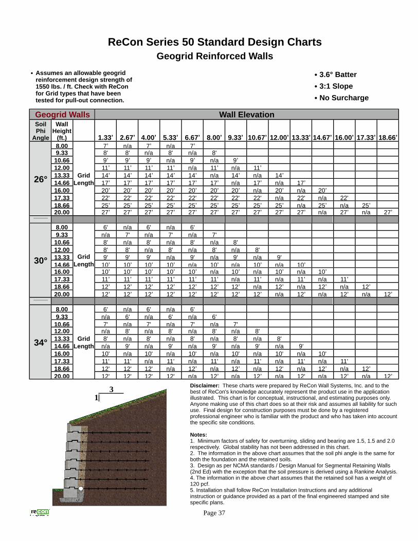
ReCon Series 50 Standard Design ChartsGeogrid Reinforced Walls
Page 37
Geogrid Walls Wall ElevationSoilPhi
Angle
WallHeight
(ft.) 1.33’ 2.67’ 4.00’ 5.33’ 6.67’ 8.00’ 9.33’ 10.67’ 12.00’ 13.33’ 14.67’ 16.00’ 17.33’ 18.66’
26°
8.00
Grid Length
7’ n/a 7’ n/a 7’9.33 8' 8' n/a 8' n/a 8'
10.66 9’ 9’ 9’ n/a 9’ n/a 9’12.00 11’ 11’ 11’ 11’ n/a 11’ n/a 11’13.33 14’ 14’ 14’ 14’ 14’ n/a 14’ n/a 14’14.66 17’ 17’ 17’ 17’ 17’ 17’ n/a 17’ n/a 17’16.00 20’ 20’ 20’ 20’ 20’ 20’ 20’ n/a 20’ n/a 20’17.33 22' 22' 22' 22' 22' 22' 22' 22' n/a 22' n/a 22'
18.66 25’ 25’ 25’ 25’ 25’ 25’ 25’ 25’ 25’ n/a 25’ n/a 25’20.00 27’ 27’ 27’ 27’ 27’ 27’ 27’ 27’ 27’ 27’ n/a 27’ n/a 27’
30°
8.00
Grid Length
6' n/a 6' n/a 6'
9.33 n/a 7' n/a 7' n/a 7'
10.66 8' n/a 8' n/a 8' n/a 8'
12.00 8' 8' n/a 8' n/a 8' n/a 8'
13.33 9' 9' 9' n/a 9' n/a 9' n/a 9'
14.66 10’ 10’ 10’ 10’ n/a 10’ n/a 10’ n/a 10’16.00 10’ 10’ 10’ 10’ 10’ n/a 10’ n/a 10’ n/a 10’17.33 11’ 11’ 11’ 11’ 11’ 11’ n/a 11’ n/a 11’ n/a 11’18.66 12’ 12’ 12’ 12’ 12’ 12’ 12’ n/a 12’ n/a 12’ n/a 12’20.00 12’ 12’ 12’ 12’ 12’ 12’ 12’ 12’ n/a 12’ n/a 12’ n/a 12’
34°
8.00
Grid Length
6' n/a 6' n/a 6'
9.33 n/a 6' n/a 6' n/a 6'
10.66 7' n/a 7' n/a 7' n/a 7'
12.00 n/a 8' n/a 8' n/a 8' n/a 8'
13.33 8' n/a 8' n/a 8' n/a 8' n/a 8'
14.66 n/a 9' n/a 9' n/a 9' n/a 9' n/a 9'
16.00 10' n/a 10' n/a 10' n/a 10' n/a 10' n/a 10'
17.33 11' 11' n/a 11' n/a 11' n/a 11' n/a 11' n/a 11'
18.66 12' 12' 12' n/a 12’ n/a 12’ n/a 12' n/a 12’ n/a 12’20.00 12' 12' 12' 12' n/a 12’ n/a 12’ n/a 12' n/a 12’ n/a 12’
• 3.6° Batter• 3:1 Slope• No Surcharge
31
• Assumes an allowable geogrid reinforcement design strength of 1550 lbs. / ft. Check with ReCon for Grid types that have been tested for pull-out connection.
Disclaimer: These charts were prepared by ReCon Wall Systems, Inc. and to the best of ReCon's knowledge accurately represent the product use in the application illustrated. This chart is for conceptual, instructional, and estimating purposes only. Anyone making use of this chart does so at their risk and assumes all liability for such use. Final design for construction purposes must be done by a registered professional engineer who is familiar with the product and who has taken into account the specific site conditions.
Notes:1. Minimum factors of safety for overturning, sliding and bearing are 1.5, 1.5 and 2.0 respectively. Global stability has not been addressed in this chart.2. The information in the above chart assumes that the soil phi angle is the same for both the foundation and the retained soils.3. Design as per NCMA standards / Design Manual for Segmental Retaining Walls (2nd Ed) with the exception that the soil pressure is derived using a Rankine Analysis. 4. The information in the above chart assumes that the retained soil has a weight of 120 pcf.5. Installation shall follow ReCon Installation Instructions and any additional instruction or guidance provided as a part of the final engineered stamped and site specific plans.

Warranty
Each Block will have a 28 day compressive strength of at least 3000 PSI for 15 years after proper installation. If a Block does not meet this warranty standard, please notify the manufacturer in writing. If after it has been determined that the Block has not met the specifications, the manufacturer will have shipped to you, replacement Blocks which shall be the manufacturer’s sole remedy for breach of this warranty. However, neither the manufacturer nor ReCon Wall Systems, Inc. shall have any obligation to install such replacement Blocks.
This warranty shall not apply to any Block which is damaged, defective or fails to meet the warranty
standard due to improper installation of the Block, chemical contact, structural design of the wall, or
excessive and unforeseen site conditions beyond the manufacturer’s or ReCon Wall Systems, Inc.’s
control.
The above warranty is the exclusive limited product warranty. ALL OTHER WARRANTIES, EXPRESS OR IMPLIED, INCLUDING WARRANTIES OF MERCHANTABILITY OR FITNESS FOR A PARTICULAR PURPOSE, ARE DISCLAIMED.
Page 38


1st Revision - April 2009
Distributed By:
ReCon Wall Systems, Inc.7600 West 27th StreetSuite 229St. Louis Park, MN 55426
(952) 922-0027(952) 922-0028 (Fax Line)www.reconwalls.com


