Curtain Wall Installation Guide - loewen.com · curtain wall to the other end of the rough opening....
7
Curtain Wall Installation Guide
Transcript of Curtain Wall Installation Guide - loewen.com · curtain wall to the other end of the rough opening....

Curtain Wall Installation Guide | 1
Curtain Wall Installation Guide
Curtain Wall Installation Guide | 3
Important Notices & Information
Manufacturer’s Notes:
The building envelope must be correctly prepared with weather
resistant barriers – that meet local and state codes. All frame and
sill surfaces must be correctly prepared for air, water, and structural
integrity by the builder or contractor before attempting installation. In
order to meet warranty requirements, all systems are required to be
installed by a certified installer.
• Loewen is not responsible for site measurements nor the structural
and architectural requirements for the installation of the
Curtain Wall.
• Any local, regional or national building code requirements
supersede these instructions.
• Building design, construction methods, building materials and site
conditions unique to your project may require methods different
from these instructions.
• Choosing the appropriate method is the responsibility of you, your
architect, or your construction professional.
• Confirm with sealant/foam/barrier manufacturers that all materials
used are compatible with one another.
Site Preparation Advisory
This manual is intended for construction professionals with proven
competency installing doors and windows for large openings. Curtain
Wall installations are complex and should not be attempted with
simple written documentation.
I M P O R TA N T N O T I C E S
!
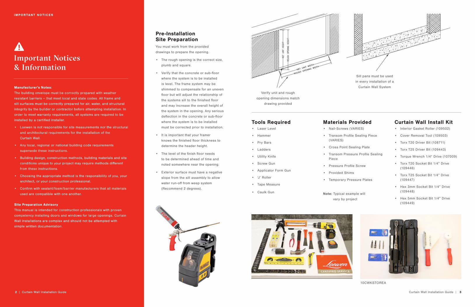
Pre-Installation Site PreparationYou must work from the provided
drawings to prepare the opening.
• The rough opening is the correct size,
plumb and square.
• Verify that the concrete or sub-floor
where the system is to be installed
is level. The frame system may be
shimmed to compensate for an uneven
floor but will adjust the relationship of
the systems sill to the finished floor
and may increase the overall height of
the system in the opening. Any serious
deflection in the concrete or sub-floor
where the system is to be installed
must be corrected prior to installation.
• It is important that your framer
knows the finished floor thickness to
determine the header height.
• The level of the finish floor needs
to be determined ahead of time and
noted somewhere near the opening.
• Exterior surface must have a negative
slope from the sill assembly to allow
water run-off from weep system
(Recommend 2 degrees).
Verify unit and rough
opening dimensions match
drawing provided
Sill pans must be used
in every installation of a
Curtain Wall System
10CWKSTOREA
Tools Required• Laser Level
• Hammer
• Pry Bars
• Ladders
• Utility Knife
• Screw Gun
• Applicator Form Gun
• ‘J’ Roller
• Tape Measure
• Caulk Gun
Materials Provided• Nail-Screws (VARIES)
• Transom Profile Sealing Piece (VARIES)
• Cross Point Sealing Plate
• Transom Pressure Profile Sealing Piece
• Pressure Profile Screw
• Provided Shims
• Temporary Pressure Plates
Note: Typical example will
vary by project
Curtain Wall Install Kit• Interior Gasket Roller (109502)
• Cover Removal Tool (109503)
• Torx T20 Driver Bit (108711)
• Torx T25 Driver Bit (109443)
• Torque Wrench 1/4“ Drive (107009)
• Torx T20 Socket Bit 1/4” Drive (109446)
• Torx T25 Socket Bit 1/4” Drive (109447)
• Hex 3mm Socket Bit 1/4” Drive (109448)
• Hex 5mm Socket Bit 1/4” Drive (109449)
2 | Curtain Wall Installation Guide
4 | Curtain Wall Installation Guide Curtain Wall Installation Guide | 5
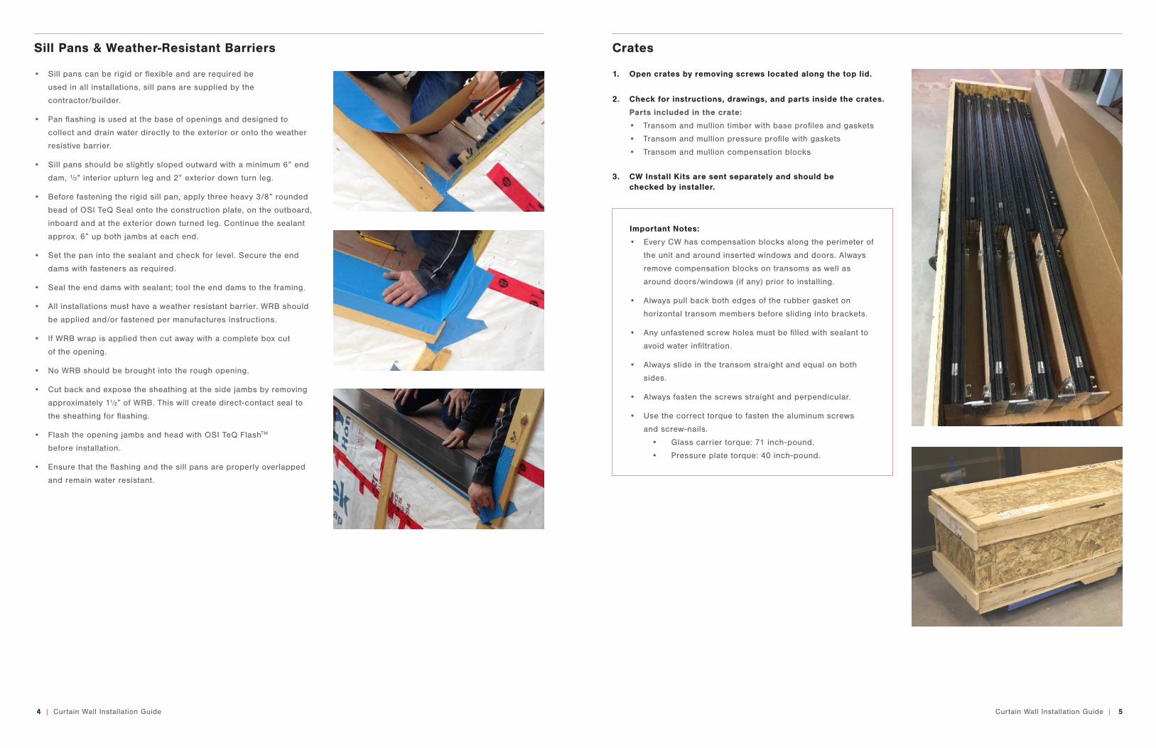
• Sill pans can be rigid or flexible and are required be
used in all installations, sill pans are supplied by the
contractor/builder.
• Pan flashing is used at the base of openings and designed to
collect and drain water directly to the exterior or onto the weather
resistive barrier.
• Sill pans should be slightly sloped outward with a minimum 6” end
dam, ½” interior upturn leg and 2” exterior down turn leg.
• Before fastening the rigid sill pan, apply three heavy 3/8” rounded
bead of OSI TeQ Seal onto the construction plate, on the outboard,
inboard and at the exterior down turned leg. Continue the sealant
approx. 6” up both jambs at each end.
• Set the pan into the sealant and check for level. Secure the end
dams with fasteners as required.
• Seal the end dams with sealant; tool the end dams to the framing.
• All installations must have a weather resistant barrier. WRB should
be applied and/or fastened per manufactures instructions.
• If WRB wrap is applied then cut away with a complete box cut
of the opening.
• No WRB should be brought into the rough opening.
• Cut back and expose the sheathing at the side jambs by removing
approximately 1½” of WRB. This will create direct-contact seal to
the sheathing for flashing.
• Flash the opening jambs and head with OSI TeQ FlashTM
before installation.
• Ensure that the flashing and the sill pans are properly overlapped
and remain water resistant.
Sill Pans & Weather-Resistant Barriers
1. Open crates by removing screws located along the top lid.
Important Notes:
• Every CW has compensation blocks along the perimeter of
the unit and around inserted windows and doors. Always
remove compensation blocks on transoms as well as
around doors/windows (if any) prior to installing.
• Always pull back both edges of the rubber gasket on
horizontal transom members before sliding into brackets.
• Any unfastened screw holes must be filled with sealant to
avoid water infiltration.
• Always slide in the transom straight and equal on both
sides.
• Always fasten the screws straight and perpendicular.
• Use the correct torque to fasten the aluminum screws
and screw-nails.
• Glass carrier torque: 71 inch-pound.
• Pressure plate torque: 40 inch-pound.
3. CW Install Kits are sent separately and should be checked by installer.
2. Check for instructions, drawings, and parts inside the crates.
Parts included in the crate:
• Transom and mullion timber with base profiles and gaskets
• Transom and mullion pressure profile with gaskets
• Transom and mullion compensation blocks
Crates
6 | Curtain Wall Installation Guide Curtain Wall Installation Guide | 7
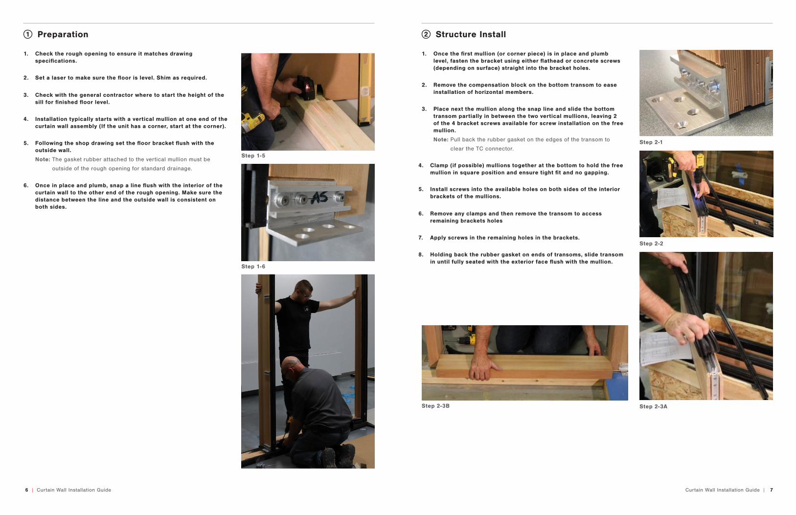
1. Check the rough opening to ensure it matches drawing specifications.
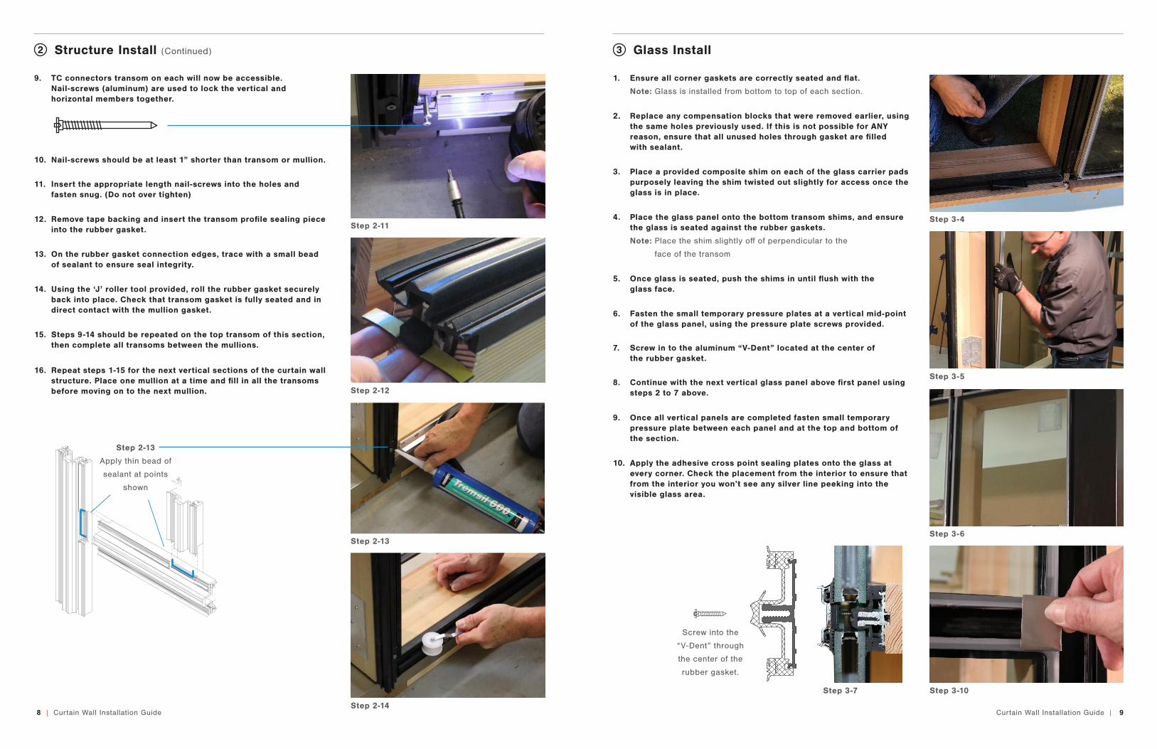
1. Once the first mullion (or corner piece) is in place and plumb level, fasten the bracket using either flathead or concrete screws (depending on surface) straight into the bracket holes.
2. Remove the compensation block on the bottom transom to ease installation of horizontal members.
4. Clamp (if possible) mullions together at the bottom to hold the free mullion in square position and ensure tight fit and no gapping.
5. Install screws into the available holes on both sides of the interior brackets of the mullions.
6. Remove any clamps and then remove the transom to access remaining brackets holes
7. Apply screws in the remaining holes in the brackets.
8. Holding back the rubber gasket on ends of transoms, slide transom in until fully seated with the exterior face flush with the mullion.
3. Place next the mullion along the snap line and slide the bottom transom partially in between the two vertical mullions, leaving 2 of the 4 bracket screws available for screw installation on the free mullion.
Note: Pull back the rubber gasket on the edges of the transom to
clear the TC connector.
2. Set a laser to make sure the floor is level. Shim as required.
5. Following the shop drawing set the floor bracket flush with the outside wall.
Note: The gasket rubber attached to the vertical mullion must be
outside of the rough opening for standard drainage.
3. Check with the general contractor where to start the height of the sill for finished floor level.
6. Once in place and plumb, snap a line flush with the interior of the curtain wall to the other end of the rough opening. Make sure the distance between the line and the outside wall is consistent on both sides.
4. Installation typically starts with a vertical mullion at one end of the curtain wall assembly (If the unit has a corner, start at the corner).
Step 2-2
Step 2-1
Step 2-3AStep 2-3B
Step 1-5
Step 1-6
Preparation Structure Install1 2
8 | Curtain Wall Installation Guide Curtain Wall Installation Guide | 9
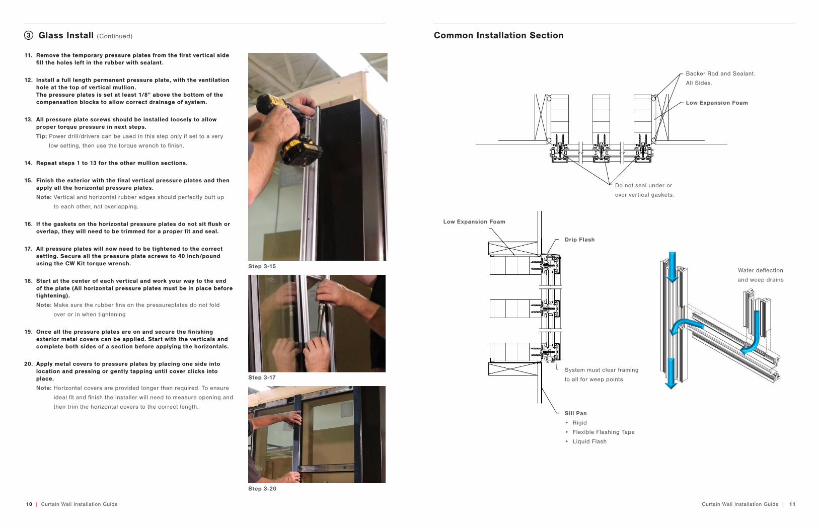
9. TC connectors transom on each will now be accessible. Nail-screws (aluminum) are used to lock the vertical and horizontal members together.
10. Nail-screws should be at least 1” shorter than transom or mullion.
11. Insert the appropriate length nail-screws into the holes and fasten snug. (Do not over tighten)
12. Remove tape backing and insert the transom profile sealing piece into the rubber gasket.
13. On the rubber gasket connection edges, trace with a small bead of sealant to ensure seal integrity.
14. Using the ‘J’ roller tool provided, roll the rubber gasket securely back into place. Check that transom gasket is fully seated and in direct contact with the mullion gasket.
15. Steps 9-14 should be repeated on the top transom of this section, then complete all transoms between the mullions.
16. Repeat steps 1-15 for the next vertical sections of the curtain wall structure. Place one mullion at a time and fill in all the transoms before moving on to the next mullion.
Structure Install (Continued)2
Step 3-7
1. Ensure all corner gaskets are correctly seated and flat.
Note: Glass is installed from bottom to top of each section.
2. Replace any compensation blocks that were removed earlier, using the same holes previously used. If this is not possible for ANY reason, ensure that all unused holes through gasket are filled with sealant.
3. Place a provided composite shim on each of the glass carrier pads purposely leaving the shim twisted out slightly for access once the glass is in place.
4. Place the glass panel onto the bottom transom shims, and ensure the glass is seated against the rubber gaskets.
Note: Place the shim slightly off of perpendicular to the
face of the transom
5. Once glass is seated, push the shims in until flush with the glass face.
6. Fasten the small temporary pressure plates at a vertical mid-point of the glass panel, using the pressure plate screws provided.
7. Screw in to the aluminum “V-Dent” located at the center of the rubber gasket.
8. Continue with the next vertical glass panel above first panel using steps 2 to 7 above.
9. Once all vertical panels are completed fasten small temporary pressure plate between each panel and at the top and bottom of the section.
10. Apply the adhesive cross point sealing plates onto the glass at every corner. Check the placement from the interior to ensure that from the interior you won’t see any silver line peeking into the visible glass area.
Glass Install3
Step 2-11
Step 2-13
Step 2-12
Step 3-4
Step 3-5
Step 2-14
Step 3-10
Step 3-6
Screw into the
“V-Dent” through
the center of the
rubber gasket.
Step 2-13
Apply thin bead of
sealant at points
shown
10 | Curtain Wall Installation Guide Curtain Wall Installation Guide | 11
16. If the gaskets on the horizontal pressure plates do not sit flush or overlap, they will need to be trimmed for a proper fit and seal.
17. All pressure plates will now need to be tightened to the correct setting. Secure all the pressure plate screws to 40 inch/pound using the CW Kit torque wrench.
19. Once all the pressure plates are on and secure the finishing exterior metal covers can be applied. Start with the verticals and complete both sides of a section before applying the horizontals.
20. Apply metal covers to pressure plates by placing one side into location and pressing or gently tapping until cover clicks into place.
Note: Horizontal covers are provided longer than required. To ensure
ideal fit and finish the installer will need to measure opening and
then trim the horizontal covers to the correct length.
18. Start at the center of each vertical and work your way to the end of the plate (All horizontal pressure plates must be in place before tightening).
Note: Make sure the rubber fins on the pressureplates do not fold
over or in when tightening
Glass Install (Continued) Common Installation Section3
Water deflection
and weep drains
System must clear framing
to all for weep points.
Sill Pan
• Rigid
• Flexible Flashing Tape
• Liquid Flash
Drip Flash
Low Expansion Foam
Step 3-17
Step 3-20
Step 3-15
11. Remove the temporary pressure plates from the first vertical side fill the holes left in the rubber with sealant.
12. Install a full length permanent pressure plate, with the ventilation hole at the top of vertical mullion. The pressure plates is set at least 1/8” above the bottom of the compensation blocks to allow correct drainage of system.
13. All pressure plate screws should be installed loosely to allow proper torque pressure in next steps.
Tip: Power drill/drivers can be used in this step only if set to a very
low setting, then use the torque wrench to finish.
14. Repeat steps 1 to 13 for the other mullion sections.
15. Finish the exterior with the final vertical pressure plates and then apply all the horizontal pressure plates.
Note: Vertical and horizontal rubber edges should perfectly butt up
to each other, not overlapping.
Low Expansion Foam
Backer Rod and Sealant.
All Sides.
Do not seal under or
over vertical gaskets.
loewen.com
Information subject to change without notice.
Distributed by Loewen Inc. in the USA and C.P. Loewen Enterprises Ltd. in Canada and internationally. Trade Marks owned by C.P. Loewen Enterprises Ltd. Used under license. © C.P. Loewen Enterprises Ltd. All rights reserved.P3153A - 0918