Cone Penetration Tests
5
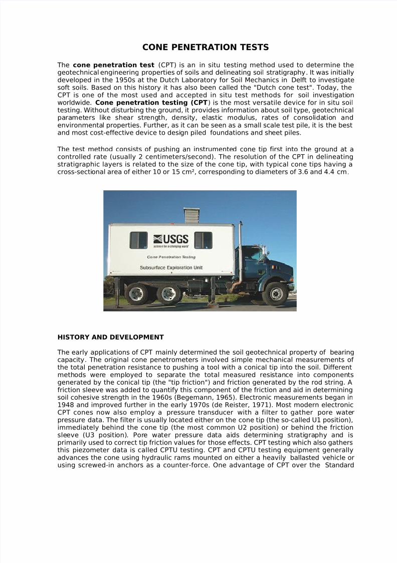
CONE PENETRATION TESTS The cone penetration test (CPT) is an in situ testing method used to determine the geotechnical engineering properties of soils and delineating soil stratigraphy . It was initially developed in the 1950s at the Dutch Laboratory for Soil Mechanics in Delft to investigate soft soils. Based on this history it has also been called the "Dutch cone test". Today, the CPT is one of the most used and accepted in situ test methods for soil investigation worldwide. Cone penetration testing (CPT ) is the most versatile device for in situ soil testing. Without disturbing the ground, it provides information about soil type, geotechnical parameters like shear str eng th, densit y, elastic modulus, rates of consolida tion and environmenta l properties. Further, as it can be seen as a small scale test pile, it is the best and most cost-effecti ve device to desi gn piled foundations and sh eet piles. The test method consists of pushing an instrumente d cone tip first into the ground at a controlled rate (usually 2 centimeters/second). The resolution of the CPT in delineating stratigraphic layers is related to the size of the cone tip, with typical cone tips having a cross-sectional area of either 10 or 15 cm², corresponding to diameters of 3.6 and 4.4 cm. HISTORY AND DEVELOPMENT The early applications of CPT mainly determined the soil geotechnical property of bearing capacity. The original cone penetrometers involved simple mechanical measurements of the total penetration resistance to pushing a tool with a conical tip into the soil. Different meth ods wer e employed to separate the total measur ed resistance into components generated by the conical tip (the "tip friction") and friction generated by the rod string. A friction sleeve was added to quantify this component of the friction and aid in determining soil cohesive strength in the 1960s (Begemann, 1965). Electronic measurements began in 1948 and improved further in the early 1970s (de Reister, 1971). Most modern electronic CPT cones now also employ a pressure transducer with a filter to gather pore wate r pressure data. The filter is usually located either on the cone tip (the so-called U1 position), immediately behind the cone tip (the most common U2 position) or behind the friction sleeve (U3 position). Por e water pressure data aids determining stratigraphy and is primarily used to correct tip friction values for those effects. CPT testing which also gathers this piezometer data is called CPTU testing. CPT and CPTU testing equipment generally advances the cone using hydraulic rams mounted on either a heavily ballasted vehicle or using screwed-in anchors as a counter-force. One advantage of CPT over the Standard
-
Upload
hiro-cerce-wilhelm-alden-abareta-tonio -
Category
Documents
-
view
232 -
download
0
Transcript of Cone Penetration Tests
7/28/2019 Cone Penetration Tests
http://slidepdf.com/reader/full/cone-penetration-tests 1/5
CONE PENETRATION TESTS
The cone penetration test (CPT) is an in situ testing method used to determine thegeotechnical engineering properties of soils and delineating soil stratigraphy. It was initiallydeveloped in the 1950s at the Dutch Laboratory for Soil Mechanics in Delft to investigatesoft soils. Based on this history it has also been called the "Dutch cone test". Today, theCPT is one of the most used and accepted in situ test methods for soil investigation worldwide. Cone penetration testing (CPT) is the most versatile device for in situ soiltesting. Without disturbing the ground, it provides information about soil type, geotechnicalparameters like shear strength, density, elastic modulus, rates of consolidation andenvironmental properties. Further, as it can be seen as a small scale test pile, it is the bestand most cost-effective device to design piled foundations and sheet piles.
The test method consists of pushing an instrumented cone tip first into the ground at acontrolled rate (usually 2 centimeters/second). The resolution of the CPT in delineatingstratigraphic layers is related to the size of the cone tip, with typical cone tips having across-sectional area of either 10 or 15 cm², corresponding to diameters of 3.6 and 4.4 cm.
HISTORY AND DEVELOPMENT
The early applications of CPT mainly determined the soil geotechnical property of bearingcapacity. The original cone penetrometers involved simple mechanical measurements of the total penetration resistance to pushing a tool with a conical tip into the soil. Differentmethods were employed to separate the total measured resistance into componentsgenerated by the conical tip (the "tip friction") and friction generated by the rod string. Afriction sleeve was added to quantify this component of the friction and aid in determining
soil cohesive strength in the 1960s (Begemann, 1965). Electronic measurements began in1948 and improved further in the early 1970s (de Reister, 1971). Most modern electronicCPT cones now also employ a pressure transducer with a filter to gather pore water pressure data. The filter is usually located either on the cone tip (the so-called U1 position),immediately behind the cone tip (the most common U2 position) or behind the frictionsleeve (U3 position). Pore water pressure data aids determining stratigraphy and isprimarily used to correct tip friction values for those effects. CPT testing which also gathersthis piezometer data is called CPTU testing. CPT and CPTU testing equipment generallyadvances the cone using hydraulic rams mounted on either a heavily ballasted vehicle orusing screwed-in anchors as a counter-force. One advantage of CPT over the Standard
7/28/2019 Cone Penetration Tests
http://slidepdf.com/reader/full/cone-penetration-tests 2/5
Penetration Test (SPT) is a more continuous profile of soil parameters, with CPTU datarecorded typically at 2cm intervals.
CF CONE (CONE PENETRATION TEST) 2.0
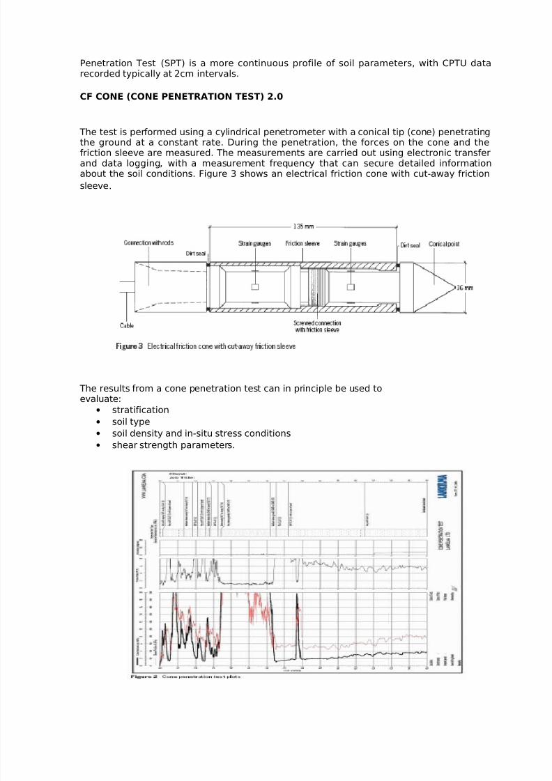
The test is performed using a cylindrical penetrometer with a conical tip (cone) penetratingthe ground at a constant rate. During the penetration, the forces on the cone and thefriction sleeve are measured. The measurements are carried out using electronic transferand data logging, with a measurement frequency that can secure detailed informationabout the soil conditions. Figure 3 shows an electrical friction cone with cut-away friction
sleeve.
The results from a cone penetration test can in principle be used toevaluate:
• stratification• soil type
• soil density and in-situ stress conditions
• shear strength parameters.
7/28/2019 Cone Penetration Tests
http://slidepdf.com/reader/full/cone-penetration-tests 3/5
The results from cone penetration tests may also be used, directly, for design of piledfoundations in sand and gravel. Indirectly, it can be used(shear strength) for piles in clay.
The test results are presented as shown in Figure 2. From left to right, the CPT plots showcone (tip) resistance, sleeve friction, friction ratio and inclination of the cone while pushing
the cone into the ground. Thefriction ratio,Rf =(f s/qc).100%, can be used to identify the soil type shown at the right-hand side of the plot.
PIEZOCONE (PIEZOCONE TEST)
PIEZOCONE
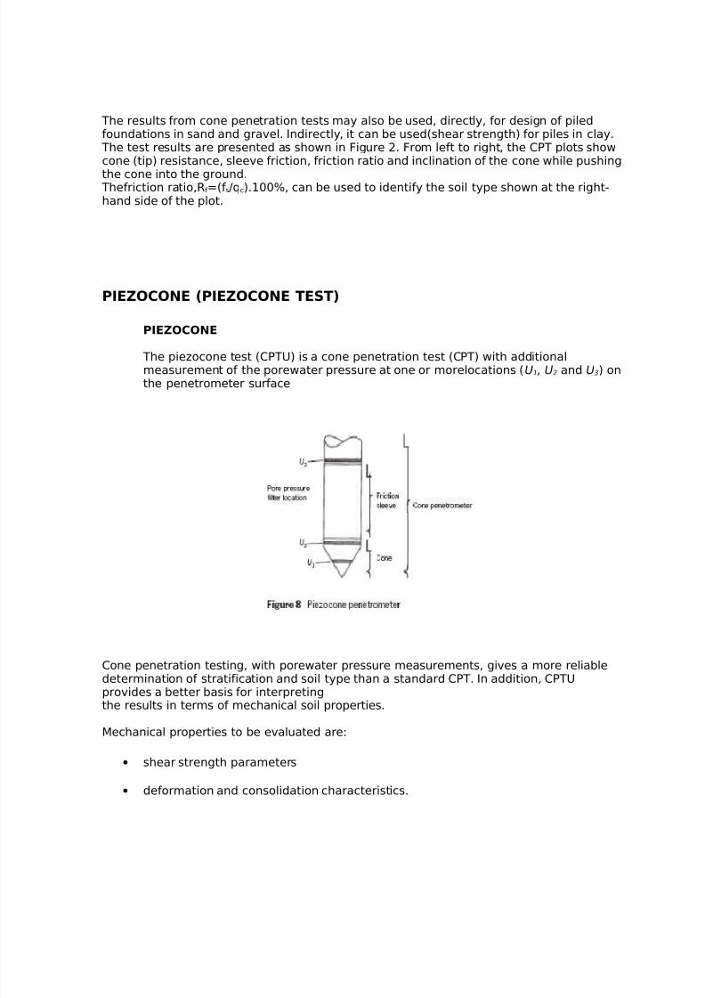
The piezocone test (CPTU) is a cone penetration test (CPT) with additionalmeasurement of the porewater pressure at one or morelocations (U1, U2 and U3) onthe penetrometer surface
Cone penetration testing, with porewater pressure measurements, gives a more reliabledetermination of stratification and soil type than a standard CPT. In addition, CPTUprovides a better basis for interpretingthe results in terms of mechanical soil properties. Mechanical properties to be evaluated are:
• shear strength parameters
• deformation and consolidation characteristics.
7/28/2019 Cone Penetration Tests
http://slidepdf.com/reader/full/cone-penetration-tests 4/5
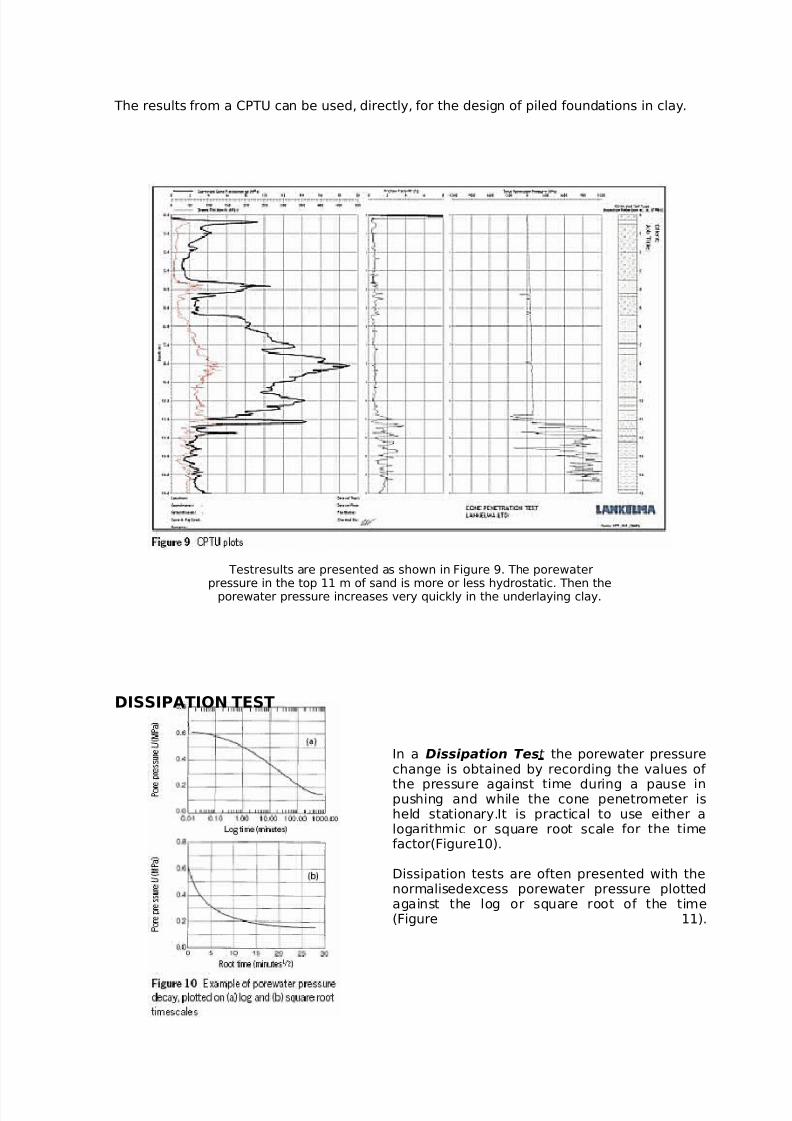
The results from a CPTU can be used, directly, for the design of piled foundations in clay.
Testresults are presented as shown in Figure 9. The porewater
pressure in the top 11 m of sand is more or less hydrostatic. Then theporewater pressure increases very quickly in the underlaying clay.
DISSIPATION TEST
In a Dissipation Test the porewater pressurechange is obtained by recording the values of
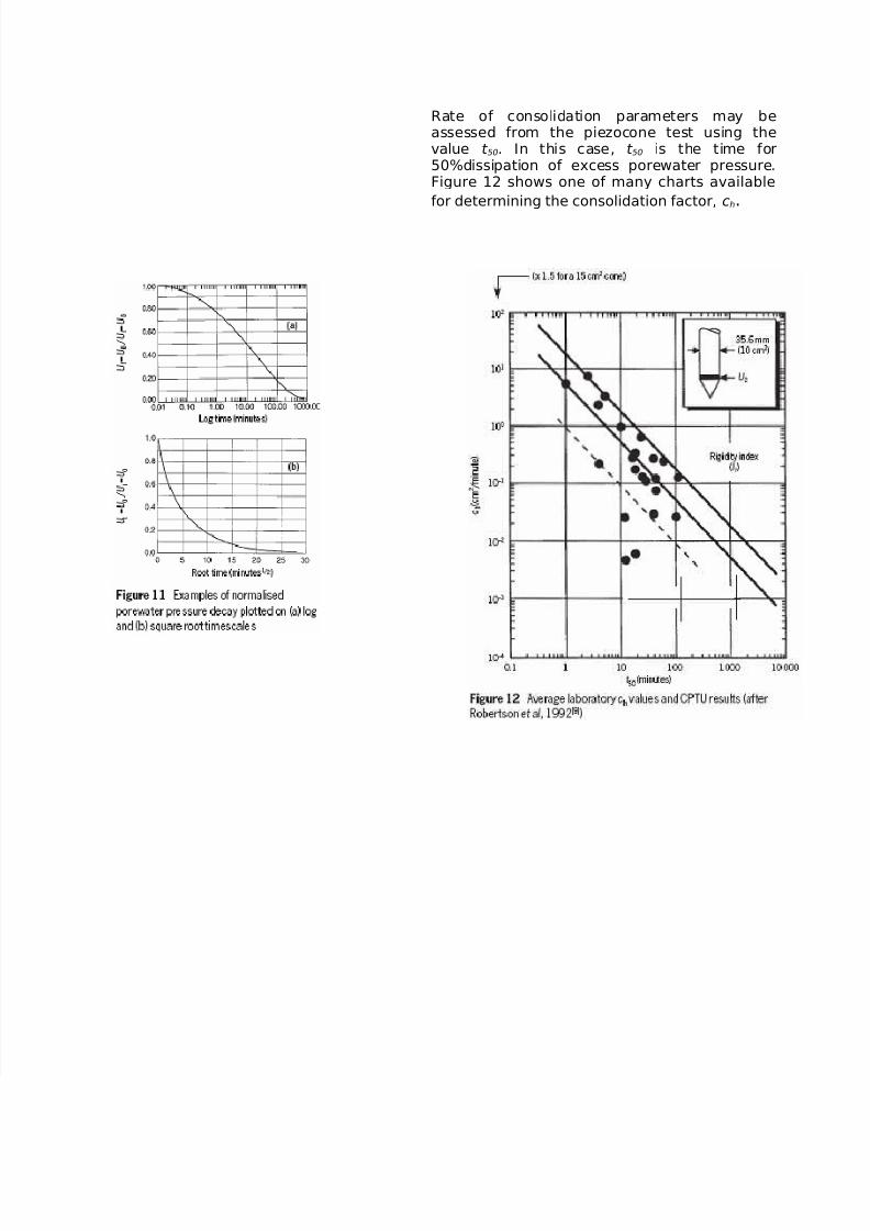
the pressure against time during a pause inpushing and while the cone penetrometer isheld stationary.It is practical to use either alogarithmic or square root scale for the timefactor(Figure10). Dissipation tests are often presented with thenormalisedexcess porewater pressure plottedagainst the log or square root of the time(Figure 11).
7/28/2019 Cone Penetration Tests
http://slidepdf.com/reader/full/cone-penetration-tests 5/5
Rate of consolidation parameters may beassessed from the piezocone test using thevalue t 50. In this case, t 50 is the time for50%dissipation of excess porewater pressure.Figure 12 shows one of many charts available
for determining the consolidation factor, ch.