Check Valve Series AK - Airline Hydraulics · PDF fileCheck Valve Series AK Large flow...
18
AS ASP ASN AQ ASV AK ASS ASR ASF 15-14-1 Check Valve Series AK Large flow capacity Low cracking pressure: 0.02 MPa A wide variation of models JIS Symbol How to Order 2 4 6 Standard size Thread type Nil N F Rc NPT G 01 02 03 04 06 10 Port size Applicable series AK2000 AK2000/4000 AK4000 AK4000 AK6000 AK6000 3 4 3 8 1 8 1 4 1 2 1 1 4 1 2 1 AK 2 000 02 Port size Model Specifications Flow Characteristics Model Effective area (mm 2 ) Port size Weight (g) AK2000-01 AK2000-02 AK4000-02 AK4000-03 AK4000-04 AK6000-06 AK6000-10 3 4 3 8 1 8 1 4 1 4 1 2 1 25 27.5 47 85 95 200 230 105 100 155 150 140 345 315 Fluid Proof pressure Maximum operating pressure Minimum operating pressure Ambient and fluid temperature Air 1.5 MPa 1 MPa 0.02 MPa –5 to 60°C (No freezing) AK2000-01/-02 AK4000-03/-04 AK6000-06/-10 AK4000-02 Pressure drop (MPa) Pressure drop (MPa) Pressure drop (MPa) Pressure drop (MPa) Flow rate (l/min (ANR)) Flow rate (l/min (ANR)) Flow rate (l/min (ANR)) Flow rate (l/min (ANR)) Inlet pressure: 0.1 MPa Inlet pressure: 0.1 MPa 0.3 MPa 0.5 MPa 0.7 MPa Inlet pressure: 0.1 MPa 0.3 MPa 0.5 MPa 0.7 MPa Inlet pressure: 0.1 MPa 0.3 MPa 0.5 MPa 0.7 MPa Inlet pressure: 0.1 MPa 0.3 MPa 0.5 MPa 0.7 MPa
Transcript of Check Valve Series AK - Airline Hydraulics · PDF fileCheck Valve Series AK Large flow...

AS
ASP
ASN
AQ
ASV
AK
ASS
ASR
ASF
15-14-1
Check Valve
Series AK Large flow capacityLow cracking pressure: 0.02 MPaA wide variation of models
JIS Symbol
How to Order
246
Standard size
Thread typeNilNF
RcNPT
G
010203040610
Port size Applicable seriesAK2000AK2000/4000AK4000AK4000AK6000AK6000
3 4
3 8
1 81 4
1 2
1
1 41 2
1
AK 2 000 02
Port size
Model
Specifications
Flow Characteristics
Model Effective area (mm2)Port size Weight (g)
AK2000-01
AK2000-02
AK4000-02
AK4000-03
AK4000-04
AK6000-06
AK6000-10
3 4
3 8
1 8
1 4
1 4
1 2
1
25
27.5
47
85
95
200
230
105
100
155
150
140
345
315
Fluid
Proof pressure
Maximum operating pressure
Minimum operating pressure
Ambient and fluid temperature
Air
1.5 MPa
1 MPa
0.02 MPa
–5 to 60°C (No freezing)
AK2000-01/-02
AK4000-03/-04 AK6000-06/-10
AK4000-02
Pre
ssur
e dr
op (M
Pa)
Pre
ssur
e dr
op (M
Pa)
Pre
ssur
e dr
op (M
Pa)
Pre
ssur
e dr
op (M
Pa)
Flow rate (l/min (ANR)) Flow rate (l/min (ANR))
Flow rate (l/min (ANR)) Flow rate (l/min (ANR))
Inle
t pre
ssur
e: 0
.1 M
Pa
Inle
t pre
ssur
e: 0
.1 M
Pa0.
3 M
Pa 0.5
MPa
0.7
MPa
Inle
t pre
ssur
e: 0
.1 M
Pa0.
3 M
Pa0.
5 M
Pa0.
7 M
Pa
Inle
t pre
ssur
e: 0
.1 M
Pa
0.3
MPa
0.5
MPa
0.7
MPa
Inle
t pre
ssur
e: 0
.1 M
Pa0.
3 M
Pa
0.5
MPa
0.7
MPa
Series AK
15-14-2
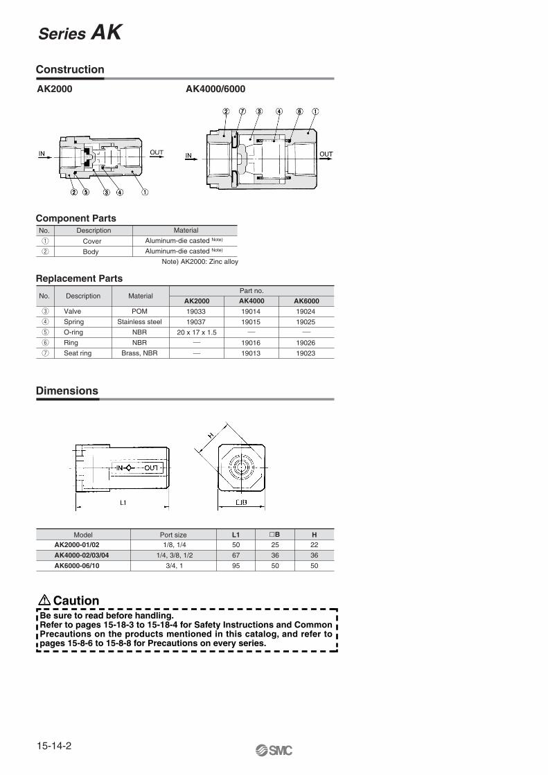
Construction
Dimensions
Component Parts
Replacement Parts
No.
No.
Description
Description
Material
MaterialPart no.
AK2000 AK4000 AK6000
q
w
e
r
t
y
u
Valve
Spring
O-ring
Ring
Seat ring
Cover
Body
POM
Stainless steel
NBR
NBR
Brass, NBR
Aluminum-die casted Note)
Aluminum-die casted Note)
19033
19037
19014
19015
19016
19013
19024
19025
19026
19023
20 x 17 x 1.5
Note) AK2000: Zinc alloy
AK2000 AK4000/6000
Model Port size L1 H�B
AK2000-01/02
AK4000-02/03/04
AK6000-06/10
50
67
95
1/8, 1/4
1/4, 3/8, 1/2
3/4, 1
25
36
50
22
36
50
CautionBe sure to read before handling. Refer to pages 15-18-3 to 15-18-4 for Safety Instructions and Common Precautions on the products mentioned in this catalog, and refer to pages 15-8-6 to 15-8-8 for Precautions on every series.

Check Valve with One-touch Fitting
Series AKH/AKBHow to Order
Thread type
Nil
N
Metric thread (M5)
Unified thread (10-32 UNF)
R
NPT
AKH 04 00Male connector type
Straight type
AKH 04 A 01 S
Check valve free flow direction
A
B
From male to female thread
From female to male thread
Applicable tubing O.D.Inch size
03
07
09
11
13
ø5/32
ø1/4
ø5/16
ø3/8
ø1/2
Metric size
Metric size
04
06
08
10
12
ø4
ø6
ø8
ø10
ø12
Port size
M5
U10/32
01
02
03
04
M5 x 0.8
10-32 UNF
1/8
1/4
3/8
1/2
With seal (Standard)∗ M5 and 10-32 UNF types are not required.
Applicable Tubing O.D./Port Size Combinations
Model
AKH04�AKH06�AKH08�AKH10�AKH12�
ø4ø6ø8
ø10ø12
Applicable tubingO.D.
R threadM5 3/81/8 1/4 1/2�
�
�
�
�
�
�
�
�
�
�
�
�
Inch size
Model
AKH03�AKH07�AKH09�AKH11�AKH13�
ø5/32ø1/4ø5/16ø3/8ø1/2
Applicable tubingO.D.
NPT thread3/81/8 1/4 1/2
�
�
�
�
�
�
�
�
�
�
�
�
�
Thread typeNil
NR
NPT
Bushing type AKB 01 A 01 S
Check valve free flow direction
Body size
R thread
01
02
03
04
1/8
1/4
3/8
1/2
Port size01
02
03
04
1/8
1/4
3/8
1/2
With seal (Standard)
Female/Male Threads Combinations
Model
AKB01�AKB02�AKB03�AKB04�
1/81/43/81/2
Female threadRc
Male thread R3/81/8 1/4 1/2
�
�
�
�
Model
AKB01�AKB02�AKB03�AKB04�
1/81/43/81/2
Female threadNPT
Male thread NPT3/81/8 1/4 1/2
�
�
�
�
NPT thread
10-32UNF
A
B
From male thread to One-touch fitting
From One-touch fitting to male thread
15-14-4
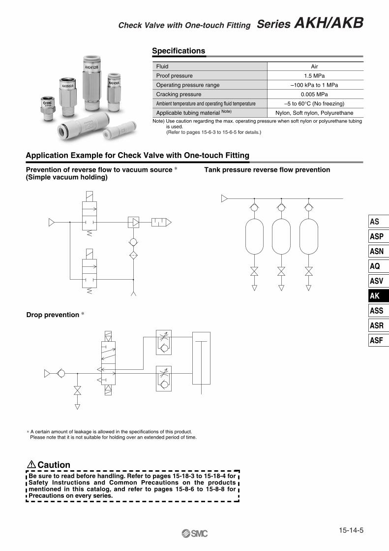
Application Example for Check Valve with One-touch Fitting
Prevention of reverse flow to vacuum source ∗ (Simple vacuum holding)
Drop prevention ∗
∗ A certain amount of leakage is allowed in the specifications of this product. Please note that it is not suitable for holding over an extended period of time.
Tank pressure reverse flow prevention
Fluid
Proof pressure
Operating pressure range
Cracking pressure
Ambient temperature and operating fluid temperature
Applicable tubing material Note)
Air
1.5 MPa
–100 kPa to 1 MPa
0.005 MPa
–5 to 60°C (No freezing)
Nylon, Soft nylon, PolyurethaneNote) Use caution regarding the max. operating pressure when soft nylon or polyurethane tubing is used. (Refer to pages 15-6-3 to 15-6-5 for details.)
Specifications
CautionBe sure to read before handling. Refer to pages 15-18-3 to 15-18-4 for Safety Instructions and Common Precautions on the products mentioned in this catalog, and refer to pages 15-8-6 to 15-8-8 for Precautions on every series.
15-14-5
Check Valve with One-touch Fitting Series AKH/AKB
AS
ASP
ASN
AQ
ASV
AK
ASS
ASR
ASF

Series AKH/AKB
15-14-6
Straight type: AKH
Dimensions
Applicable tubing O.D.
Applicable tubing O.D.
Applicable tubing O.D.
Applicable tubing O.D.
Model
AKH04-00AKH06-00AKH08-00AKH10-00AKH12-00
øD
9.311.615.218.521.7
L
33.537.153.363.670.2
M
12.713.518.521 22
468
1012
Effective area (mm2)
2.86.5
142434
Weight(g)
35
101725
Metric Size
Model
AKH03-00AKH07-00AKH09-00AKH11-00AKH13-00
øD
9.31215.218.521.7
L
33.53953.363.670.2
M
12.713.618.52122
5/321/4
5/163/81/2
Effective area (mm2)
2.8 6.5142434
Weight(g)
36
101724
Inch Size
4
6
8
10
12
Metric Size
AKH04�-M5AKH04�-01SAKH06�-M5AKH06�-01SAKH06�-02SAKH08�-01SAKH08�-02SAKH08�-03SAKH10�-02SAKH10�-03SAKH10�-04SAKH12�-03SAKH12�-04S
810
10
14
14
17
17
221922
L
24.324.625.826.930 31.7
42
54.347.349.360.554.5
M
12.7
13.5
17
18.5
21
22
A ∗
21.220.622.222.92427.73635.548.340.841.35446.5
Effective area (mm2)
2.8
2.86.56.56.5
14
24
34
Connection threadR
M5 x 0.81/8
M5 x 0.81/81/41/81/43/81/43/81/23/81/2
Weight(g)
510
221624434539806280
H(Hexagon width
across flats)
5/32
1/4
5/16
3/8
1/2
Inch Size
AKH03�-U10/32AKH03�-N01SAKH07�-U10/32AKH07�-N01SAKH07�-N02SAKH09�-N01SAKH09�-N02SAKH09�-N03SAKH11�-N02SAKH11�-N03SAKH11�-N04SAKH13�-N03SAKH13�-N04S
811.11
11.11
14.29
14.29
17.46
17.46
22.23
22.23
L
24.324.625.826.931 31.7
42
54.247.249.260.554.5
M
12.7
13.6
17
18.5
21
22
A ∗
21.220.622.722.92527.73635.548.340.741.25446.5
Effective area (mm2)
2.8
2.86.56.56.5
14
24
34
Connection threadNPT
10-32 UNF1/8
10-32 UNF1/81/41/81/43/81/43/81/23/81/2
Weight(g)
5101011181624434740798785
H(Hexagon width
across flats)
∗ Reference dimensions of R thread after installation.
∗ Reference dimensions of NPT thread after installation.
Connection thread size R
1/81/43/81/2
1/81/43/81/2
Metric Size
Model
AKB01�-01SAKB02�-02SAKB03�-03SAKB04�-04S
H
14172224
L
23.739.845.256.2
A ∗
19.733.838.748.2
Effective area (mm2) 6.5142434
Weight(g)
Effective area (mm2)
Weight(g)
184486
113
∗ Reference dimensions of R thread after installation.
� �
Connection thread size NPT
1/81/43/81/2
1/81/43/81/2
Inch Size
Model
AKB01�-N01SAKB02�-N02SAKB03�-N03SAKB04�-N04S
H
14.2917.4622.2323.81
L
24.240 44.955.5
A ∗
20.234 38.447.5
6.5142434
184486
113
∗ Reference dimensions of NPT thread after installation.
Male connector type: AKH
<For M5, UNF10-32>
<For R, NPT>
Bushing type: AKB
2-Applicable tubing
M M
øD
L
L
A
M
H
Applicable tubing
Connection thread
L
A
M
H
Applicable tubing
Connectionthread
L
A
H
Connection thread size �
Connection thread size �
8
� �
Model
Model
15-14-7
Check Valve with One-touch Fitting Series AKH/AKB
AS
ASP
ASN
AQ
ASV
AK
ASS
ASR
ASF
ø4, ø6ø5/32, ø1/4
ø8, ø10, ø12ø5/16, ø3/8, ø1/2
ø4, ø6ø8 x R 1/8ø5/32, ø1/4ø5/16 x NPT 1/8
ø8, ø10, ø12ø5/16, ø3/8, ø1/2
Free flowOne-touch
fitting�
Malethread
Free flowOne-touch
fitting�
Malethread
R 1/8NPT 1/8M5 type
U10/32
R 1/4, 3/8, 1/2NPT 1/4, 3/8, 1/2
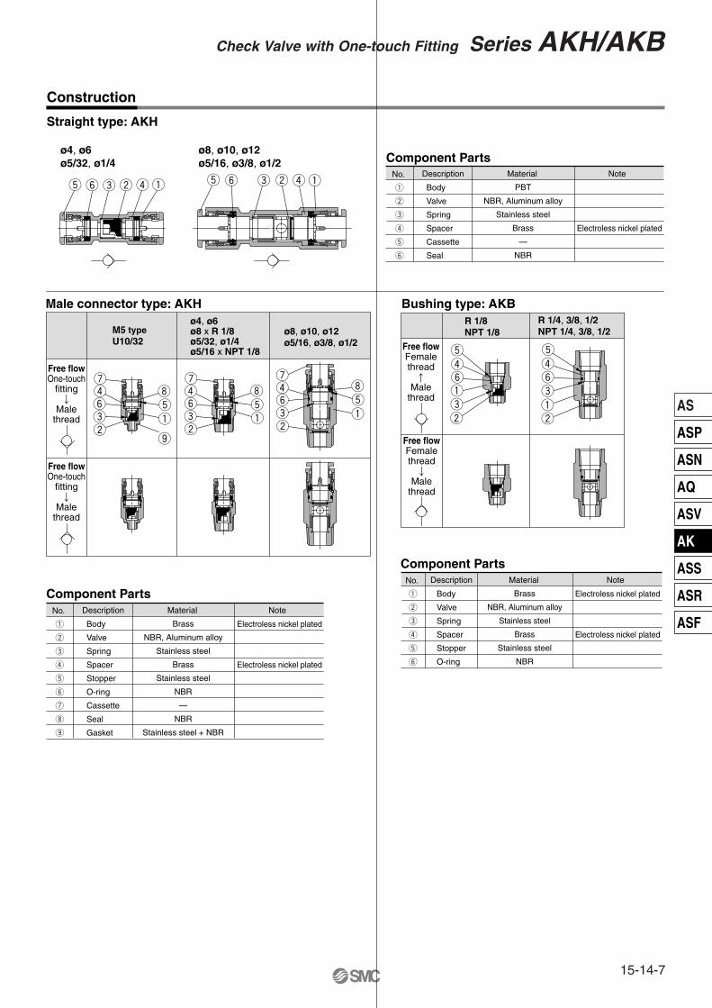
Straight type: AKH
Construction
Male connector type: AKH Bushing type: AKB
No.
q
w
e
r
t
y
u
i
o
Description Material Note
Component Parts
Component Parts
Body
Valve
Spring
Spacer
Stopper
O-ring
Cassette
Seal
Gasket
Brass
NBR, Aluminum alloy
Stainless steel
Brass
Stainless steel
NBR
—
NBR
Stainless steel + NBR
Electroless nickel plated
Electroless nickel plated
No.
q
w
e
r
t
y
Description Material Note
Body
Valve
Spring
Spacer
Stopper
O-ring
Brass
NBR, Aluminum alloy
Stainless steel
Brass
Stainless steel
NBR
Electroless nickel plated
Electroless nickel plated
No.
q
w
e
r
t
y
Description Material Note
Component Parts
Body
Valve
Spring
Spacer
Cassette
Seal
PBT
NBR, Aluminum alloy
Stainless steel
Brass
—
NBR
Electroless nickel plated
t y e w r q t y e w r q
Free flowFemalethread
�Male
thread
Free flowFemalethread
�Male
thread
uitq
o
ryew
tr
qy
ew
tr
ey
qw
itq
uryew
itq
uryew
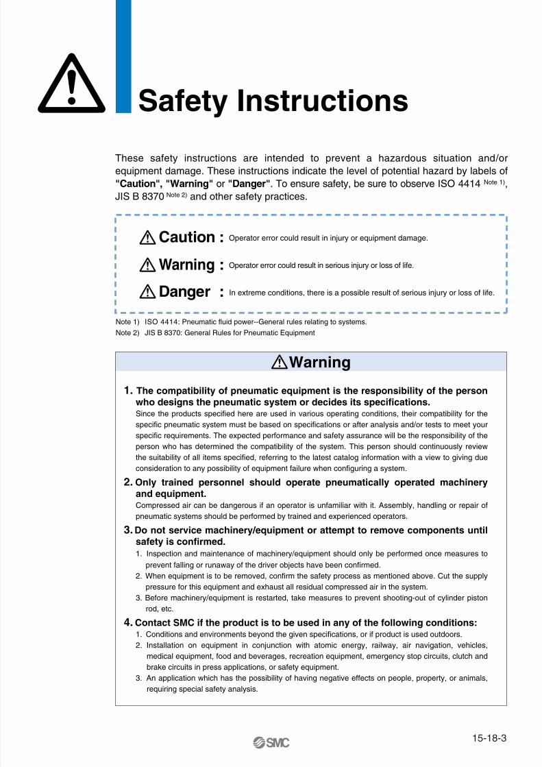
Safety Instructions
These safety instructions are intended to prevent a hazardous situation and/or equipment damage. These instructions indicate the level of potential hazard by labels of "Caution", "Warning" or "Danger". To ensure safety, be sure to observe ISO 4414 Note 1), JIS B 8370 Note 2) and other safety practices.
1. The compatibility of pneumatic equipment is the responsibility of the person who designs the pneumatic system or decides its specifications.Since the products specified here are used in various operating conditions, their compatibility for the specific pneumatic system must be based on specifications or after analysis and/or tests to meet your specific requirements. The expected performance and safety assurance will be the responsibility of the person who has determined the compatibility of the system. This person should continuously review the suitability of all items specified, referring to the latest catalog information with a view to giving due consideration to any possibility of equipment failure when configuring a system.
2. Only trained personnel should operate pneumatically operated machinery and equipment.Compressed air can be dangerous if an operator is unfamiliar with it. Assembly, handling or repair of pneumatic systems should be performed by trained and experienced operators.
3. Do not service machinery/equipment or attempt to remove components until safety is confirmed.1. Inspection and maintenance of machinery/equipment should only be performed once measures to
prevent falling or runaway of the driver objects have been confirmed. 2. When equipment is to be removed, confirm the safety process as mentioned above. Cut the supply
pressure for this equipment and exhaust all residual compressed air in the system.3. Before machinery/equipment is restarted, take measures to prevent shooting-out of cylinder piston
rod, etc.
4. Contact SMC if the product is to be used in any of the following conditions:1. Conditions and environments beyond the given specifications, or if product is used outdoors.2. Installation on equipment in conjunction with atomic energy, railway, air navigation, vehicles,
medical equipment, food and beverages, recreation equipment, emergency stop circuits, clutch and brake circuits in press applications, or safety equipment.
3. An application which has the possibility of having negative effects on people, property, or animals, requiring special safety analysis.
Note 1) ISO 4414: Pneumatic fluid power--General rules relating to systems.
Note 2) JIS B 8370: General Rules for Pneumatic Equipment
Warning
Caution : Operator error could result in injury or equipment damage.
Warning : Operator error could result in serious injury or loss of life.
Danger : In extreme conditions, there is a possible result of serious injury or loss of life.
15-18-3

1. Confirm the specifications.Products represented in this catalog are designed for use in compressed air appllications only (including vacuum), unless otherwise indicated.Do not use the product outside their design parameters.Please contact SMC when using the products in applications other than compressed air (including vacuum).
4. Use clean airIf the compressed air supply is contaminated with chemicals, cynthetic materials, corrosive gas, etc., it may lead to break down or malfunction.
Selection
Mounting
Piping
Air Supply
Maintenance
Operating Environment
Warning
1. Instruction manualInstall the products and operate them only after reading the instruction manual carefully and understanding its contents. Also keep the manual where it can be referred to as necessary.
2. Securing the space for maintenanceWhen installing the products, please allow access for maintenance.
3. Tightening torqueWhen installing the products, please follow the listed torque specifications.
Warning
1. Do not use in environments where the product is directly exposed to corrosive gases, chemicals, salt water, water or steam.
2. Do not expose the product to direct sunlight for an extended period of time.
3. Do not use in a place subject to heavy vibrations and/or shocks.
4. Do not mount the product in locations where it is exposed to radiant heat.
Warning
1. Maintenance procedures are outlined in the operation manual.Not following proper procedures could cause the product to malfunction and could lead to damage to the equipment or machine.
2. Maintenance workIf handled improperly, compressed air can be dangerous.Assembly, handling and repair of pneumatic systems should be performed by qualified personnel only.
3. Drain flushingRemove drainage from air filters regularly. (Refer to the specifications.)
4. Shut-down before maintenanceBefore attempting any kind of maintenance make sure the supply pressure is shut of and all residual air pressure is released from the system to be worked on.
5. Start-up after maintenance and inspectionApply operating pressure and power to the equipment and check for proper operation and possible air leaks. If operation is abnormal, please verify product set-up parameters.
6. Do not make any modifications to be product.Do not take the product apart.
Warning
1. Before pipingMake sure that all debris, cutting oil, dust, etc, are removed from the piping.
2. Wrapping of pipe tapeWhen screwing piping or fittings into ports, ensure that chips from the pipe threads or sealing material do not get inside the piping. Also, when the pipe tape is used, leave 1.5 to 2 thread ridges exposed at the end of the threads.
Caution
1. Operating fluidPlease consult with SMC when using the product in applications other than compressed air (including vacuum).Regarding products for general fluid, please ask SMC about applicable fluids.
2. Install an air dryer, aftercooler, etc.Excessive condensate in a compressed air system may cause valves and other pneumatic equipment to malfunction.Installation of an air dryer, after cooler etc. is recommended.
3. Drain flushingIf condensate in the drain bowl is not emptied on a regular basis, the bowl will over flow and allow the condensate to enter the compressed air lines.If the drain bowl is difficult to check and remove, it is recommended that a drain bowl with the auto-drain option be installed.For compressed air quality, refer to “Air Preparation Equipment” catalog.
Warning
Common PrecautionsBe sure to read before handling.For detailed precautions on every series, refer to main text.
15-18-4

Quality Assurance Information(ISO 9001, ISO 14001)
Reliable quality of products in the global market
To enable our customers throughout the world to use our products with even greater confidence, SMC has obtained certification for international standards “ISO 9001” and “ISO 14001”, and created a complete structure for quality assurance and environmental controls. SMC products pursue to meet its customers’ expectations while also considering company’s contribution in society.
This is an international standard for quality control and quality assurance. SMC has obtained a large number of certifications in Japan and overseas, providing assurance to our customers throughout the world.
Quality management system
ISO 9001
This is an international standard related to environmental management systems and environmental inspections. While promoting environmentally friendly automation technology, SMC is also making diligent efforts to preserve the environment.
Environmental management system
ISO 14001
Sales coordination
Production
Make customers our first priority, offering them reliable and friendly service.
Market researchProduct planningAfter service
Process controlInspection, testing, etc.Initial production control
Quality system educationTraining of suppliers
New product evaluationReliability designReliability testingNew technical development
EducationTraining
ResearchDesignDevelopment
Produce the highest quality with the participation of all employees.
Create new products using the latest technology, and offer the finest products in a timely manner.
SMC’s quality control system
Quality policies
Quality control activities
15-18-5
CE Mark
SMC Product Conforming to Inter
SMC products complying with EN/ISO, CSA/UL standards are supporting
The CE mark indicates that machines and components meet essential requirements of all the EC Directives applied.It has been obligatory to apply CE marks indicating conformity with EC Directives when machines and components are exported to the member Nations of the EU. Once “A manufacturer himself” declares a product to be safe by means of CE marking (declaration of conformity by manufacturer), free distribution inside the member Nations of the EU is permissible.
� CE MarkSMC provides CE marking to products to which EMC and Low Voltage Directives have been applied, in accordance with CETOP (European hydraulics and pneumatics committee) guide lines.
� As of February 1998, the following 18 countries will be obliged to conform to CE mark legislationIceland, Ireland, United Kingdom, Italy, Austria, Netherlands, Greece, Liechtenstein, Sweden, Spain, Denmark, Germany, Norway, Finland, France, Belgium, Portugal, Luxembourg
� EC Directives and Pneumatic Components• Machinery DirectiveThe Machinery Directive contains essential health and safety requirements for machinery, as applied to industrial machines e.g. machine tools, injection molding machines and automatic machines. Pneumatic equipment is not specified in Machinery Directive. However, the use of SMC products that are certified as conforming to EN Standards, allows customers to simplify preparation work of the Technical Construction File required for a Declaration of Conformity.
• Electromagnetic Compatibility (EMC) DirectiveThe EMC Directive specifies electromagnetic compatibility. Equipment which may generate electromagnetic interference or whose function may be compromised by electromagnetic interference is required to be immune to electromagnetic affects (EMS/immunity) without emitting excessive electromagnetic affects (EMI/emission).
• Low Voltage DirectiveThis directive is applied to products, which operate above 50 VAC to 1000 VAC and 75 VDC to 1500 VDC operating voltage, and require electrical safety measures to be introduced.
• Simple Pressure Vessels DirectiveThis directive is applied to welded vessels whose maximum operating pressure (PS) and volume of vessel (V) exceed 50 bar/L. Such vessels require EC type examination and then CE marking.
15-18-6

http://www.smcworld.com
you to comply with EC directives and CSA/UL standards.
� CSA Standards & UL StandardsUL and CSA standards have been applied in North America (U.S.A. and Canada) symbolizing safety of electric products, and are defined to mainly prevent danger from electric shock or fire, resulting from trouble with electric products. Both UL and CSA standards are acknowledged in North America as the first class certifying body. They have a long experience and ability for issuing product safety certificate. Products approved by CSA or UL standards are accepted in most states and governments beyond question.Since CSA is a test certifying body as the National Recognized Testing Laboratory (NRTL) within the jurisdiction of Occupational Safety and Health Administration (OSHA), SMC was tested for compliance with CSA Standards and UL Standards at the same time and was approved for compliance with the two Standards. The above CSA NRTL/C logo is described on a product label in order to indicate that the product is approved by CSA and UL Standards.
� TSSA (MCCR) Registration Products TSSA is the regulation in Ontario State, Canada. The products that the operating pressure is more than 5 psi (0.03 MPa) and the piping size is bigger than 1 inch. fall into the scope of TSSA regulation.
Products conforming to CE Standard
With CE symbol for simple visual recognition
In this catalog each accredited product series is indicated with a CE mark symbol. However, in some cases, every available models may not meet CE compliance. Please visit our web site for the latest selection of available models with CE mark.
Mark of compliance for CSA
Mark of compliance for CSA/UL
national Standards
15-18-7
SMC Product Conforming to International Standards

America EuropeU.S.A. SMC Corporation of America3011 North Franklin Road Indianapolis, IN 46226, U.S.A.TEL: 317-899-4440 FAX: 317-899-3102
CANADA SMC Pneumatics (Canada) Ltd.6768 Financial Drive Mississauga, Ontario, L5N 7J6 CanadaTEL: 905-812-0400 FAX: 905-812-8686
MEXICO SMC Corporation (Mexico), S.A. DE C.V.Carr. Silao-Trejo K.M. 2.5 S/N, Predio San Jose del DuranzoC.P. 36100, Silao, Gto., MexicoTEL: 472-72-2-55-00 FAX: 472-72-2-59-44/2-59-46
CHILE SMC Pneumatics (Chile) S.A.Av. La Montaña 1,115 km. 16,5 P. Norte ParqueIndustrial Valle Grande, Lampa Santiago, ChileTEL: 02-270-8600 FAX: 02-270-8601
ARGENTINA SMC Argentina S.A.Teodoro Garcia 3860 (1427) Buenos Aires, ArgentinaTEL: 011-4555-5762 FAX: 011-4555-5762
BOLIVIA SMC Pneumatics Bolivia S.R.L.Avenida Beni Numero 4665Santa Cruz de la Sierra-Casilla de Correo 2281, BoliviaTEL: 591-3-3428383 FAX: 591-3-3449900
VENEZUELA SMC Neumatica Venezuela S.A. Apartado 40152, Avenida Nueva Granada, Edificio Wanlac,Local 5, Caracas 1040-A, VenezuelaTEL: 2-632-1310 FAX: 2-632-3871
PERU (Distributor) IMPECO Automatizacion Industrial S.A. AV. Canevaro 752, Lince, Lima, PeruTEL: 1-471-6002 FAX: 1-471-0935
URUGUAY (Distributor) BAKO S.A. Galicia 1650 esq. Gaboto C.P. 11200, Montevideo, UruguayTEL: 2-401-6603 FAX: 2-409-4306
BRAZIL SMC Pneumaticos Do Brasil Ltda.Rua. Dra. Maria Fidelis, nr. 130, Jardim Piraporinha-Diadema-S.P. CEP: 09950-350, BrasilTEL: 11-4051-1177 FAX: 11-4071-6636
COLOMBIA (Distributor) Airmatic Ltda.Calle 18 69-05 Apart. Aereo 081045 Santa Fe de Bogotá, ColombiaTEL: 1-424-9240 FAX: 1-424-9260
U.K. SMC Pneumatics (U.K.) Ltd.Vincent Avenue, Crownhill, Milton Keynes, MK8 0AN, Backinghamshire, U.K.TEL: 01908-563888 FAX: 01908-561185
GERMANY SMC Pneumatik GmbHBoschring 13-15 D-63329 Egelsbach, GermanyTEL: 06103-4020 FAX: 06103-402139
ITALY SMC Italia S.p.A.Via Garibaldi 62 I-20061 Carugate Milano, ItalyTEL: 02-9271365 FAX: 02-9271365
FRANCE SMC Pneumatique S.A.1 Boulevard de Strasbourg, Parc Gustave Eiffel, Bussy Saint Georges, F-77600Marne La Vallee Cedex 3 FranceTEL: 01-64-76-10-00 FAX: 01-64-76-10-10
SWEDEN SMC Pneumatics Sweden ABEkhagsvägen 29-31, S-141 05 Huddinge, SwedenTEL: 08-603-07-00 FAX: 08-603-07-10
SWITZERLAND SMC Pneumatik AGDorfstrasse 7, Postfach 117, CH-8484 Weisslingen, SwitzerlandTEL: 052-396-3131 FAX: 052-396-3191
AUSTRIA SMC Pneumatik GmbH (Austria)Girakstrasse 8, A-2100 Korneuburg, AustriaTEL: 0-2262-6228-0 FAX: 0-2262-62285
SPAIN SMC España, S.A.Zuazobidea 14 Pol. Ind. Júndiz 01015 Vitoria, SpainTEL: 945-184-100 FAX: 945-184-510
IRELAND SMC Pneumatics (Ireland) Ltd.2002 Citywest Business Campus, Naas Road, Saggart, Co. Dublin, IrelandTEL: 01-403-9000 FAX: 01-466-0385
NETHERLANDS (Associated company) SMC Pneumatics BVDe Ruyterkade 120, NL-1011 AB Amsterdam, NetherlandsTEL: 020-5318888 FAX: 020-5318880
GREECE (Distributor) S.Parianopoulos S.A.7, Konstantinoupoleos Street 11855 Athens, GreeceTEL: 01-3426076 FAX: 01-3455578
DENMARK SMC Pneumatik A/SKnudsminde 4 B DK-8300Odder, DenmarkTEL: 70252900 FAX: 70252901
SMC’s Global Service Network
15-18-20

EuropeFINLAND SMC Pneumatics Finland OYPL72, Tiistinniityntie 4, SF-02231 ESP00, FinlandTEL: 09-8595-80 FAX: 09-8595-8595
NORWAY SMC Pneumatics Norway A/SVollsveien 13C, Granfoss Næringspark N-1366 LYSAKER, NorwayTEL: 67-12-90-20 FAX: 67-12-90-21
BELGIUM (Distributor) SMC Pneumatics N.V./S.A.Nijverheidsstraat 20 B-2160 Wommelgem BelguimTEL: 03-355-1464 FAX: 03-355-1466
POLAND SMC Industrial Automation Polska Sp.z.o.o.ul. Konstruktorska 11A, PL-02-673 Warszawa, PolandTEL: 022-548-5085 FAX: 022-548-5087
TURKEY (Distributor) Entek Pnömatik San.ve Tic. Ltd. StiPerpa Tic. Merkezi Kat:11 No.1625 80270 Okmeydani Istanbul, TürkiyeTEL: 0212-221-1512 FAX: 0212-221-1519
RUSSIA SMC Pneumatik LLC.36/40 Sredny prospect V.O. St. Petersburg 199004, RussiaTEL: 812-118-5445 FAX: 812-118-5449
CZECH SMC Industrial Automation CZ s.r.o.Hudcova 78a, CZ-61200 Brno, Czech RepublicTEL: 05-4121-8034 FAX: 05-4121-8034
HUNGARY SMC Hungary Ipari Automatizálási kft.Budafoki ut 107-113 1117 BudapestTEL: 01-371-1343 FAX: 01-371-1344
ROMANIA SMC Romania S.r.l.Str. Frunzei, Nr. 29, Sector 2, Bucharest, RomaniaTEL: 01-3205111 FAX: 01-3261489
SLOVAKIA SMC Priemyselná automatizáciá, s.r.oNova 3, SK-83103 BratislavaTEL: 02-4445-6725 FAX: 02-4445-6028
SLOVENIA SMC Industrijska Avtomatilca d.o.o.Grajski trg 15, SLO- 8360 Zuzemberk, SloveniaTEL: 07388-5240 FAX: 07388-5249
SOUTH AFRICA (Distributor) Hyflo Southern Africa (Pty.) Ltd.P.O.Box 240 Paardeneiland 7420 South AfricaTEL: 021-511-7021 FAX: 021-511-4456
EGYPT (Distributor) Saadani Trading & Ind. Services15 Sebaai Street, Miami 21411 Alexandria, EgyptTEL: 3-548-50-34 FAX: 3-548-50-34
Oceania/AsiaAUSTRALIA SMC Pneumatics (Australia) Pty.Ltd.14-18 Hudson Avenue Castle Hill NSW 2154, AustraliaTEL: 02-9354-8222 FAX: 02-9894-5719
NEW ZEALAND SMC Pneumatics (New Zealand) Ltd.8C Sylvia Park Road Mt.Wellington Auckland, New ZealandTEL: 09-573-7007 FAX: 09-573-7002
TAIWAN SMC Pneumatics (Taiwan) Co.,Ltd.17, Lane 205, Nansan Rd., Sec.2, Luzhu-Hsiang, Taoyuan-Hsien, TAIWANTEL: 03-322-3443 FAX: 03-322-3387
HONG KONG SMC Pneumatics (Hong Kong) Ltd. 29/F, Clifford Centre, 778-784 Cheung, Sha Wan Road, Lai Chi Kok, Kowloon,Hong KongTEL: 2744-0121 FAX: 2785-1314
SINGAPORE SMC Pneumatics (S.E.A.) Pte. Ltd.89 Tuas Avenue 1, Jurong Singapore 639520TEL: 6861-0888 FAX: 6861-1889
PHILIPPINES SHOKETSU SMC CorporationUnit 201 Common Goal Tower, Madrigal Business Park,Ayala Alabang Muntinlupa, PhilippinesTEL: 02-8090565 FAX: 02-8090586
MALAYSIA SMC Pneumatics (S.E.A.) Sdn. Bhd.Lot 36 Jalan Delima1/1, Subang Hi-Tech Industrial Park, Batu 3 40000 Shah AlamSelangor, MalaysiaTEL: 03-56350590 FAX: 03-56350602
SOUTH KOREA SMC Pneumatics Korea Co., Ltd.Woolim e-BIZ Center (Room 1008), 170-5, Guro-Dong, Guro-Gu,Seoul, 152-050, South KoreaTEL: 02-3219-0700 FAX: 02-3219-0702
CHINA SMC (China) Co., Ltd.7 Wan Yuan St. Beijing Economic & Technological Development Zone 100176, China TEL: 010-67882111 FAX: 010-67881837
THAILAND SMC Thailand Ltd.134/6 Moo 5, Tiwanon Road, Bangkadi, Amphur Muang, Patumthani 12000, ThailandTEL: 02-963-7099 FAX: 02-501-2937
INDIA SMC Pneumatics (India) Pvt. Ltd.D-107 to 112, Phase-2, Extension, Noida, Dist. Gautaim Budh Nagar,U.P. 201 305, IndiaTEL: (0120)-4568730 FAX: 0120-4568933
INDONESIA (Distributor) P.T. Riyadi Putera MakmurJalan Hayam Wuruk Komplek Glodok Jaya No. 27-28 Jakarta 11180 IndonesiaTEL: 021-625 5548 FAX: 021-625 5888
PAKISTAN (Distributor) Jubilee CorporationFirst Floor Mercantile Centre, Newton Road Near Boulton Market P.O. Box 6165 Karachi 74000 PakistanTEL: 021-243-9070/8449 FAX: 021-241-4589
ISRAEL (Distributor) Baccara Automation ControlKvutzat Geva 18915 IsraelTEL: 04-653-5960 FAX: 04-653-1445
SAUDI ARABIA (Distributor) Assaggaff Trading Est.P.O. Box 3385 Al-Amir Majed Street, Jeddah-21471, Saudi ArabiaTEL: 02-6761574 FAX: 02-6708173
15-18-21
SMC’s Global Service Network
AK
How to Order
Check Valve
Series AK
000 02N 2
Area Code
Nil
N
Japan, Asia,Australia, UK
U.S.A.
Body size
Port thread
Port size
246
NF
RcNPT
G
Nil
010203040610
AK2000AK2000, 4000AK4000AK4000AK6000AK6000
Port size Applicable series
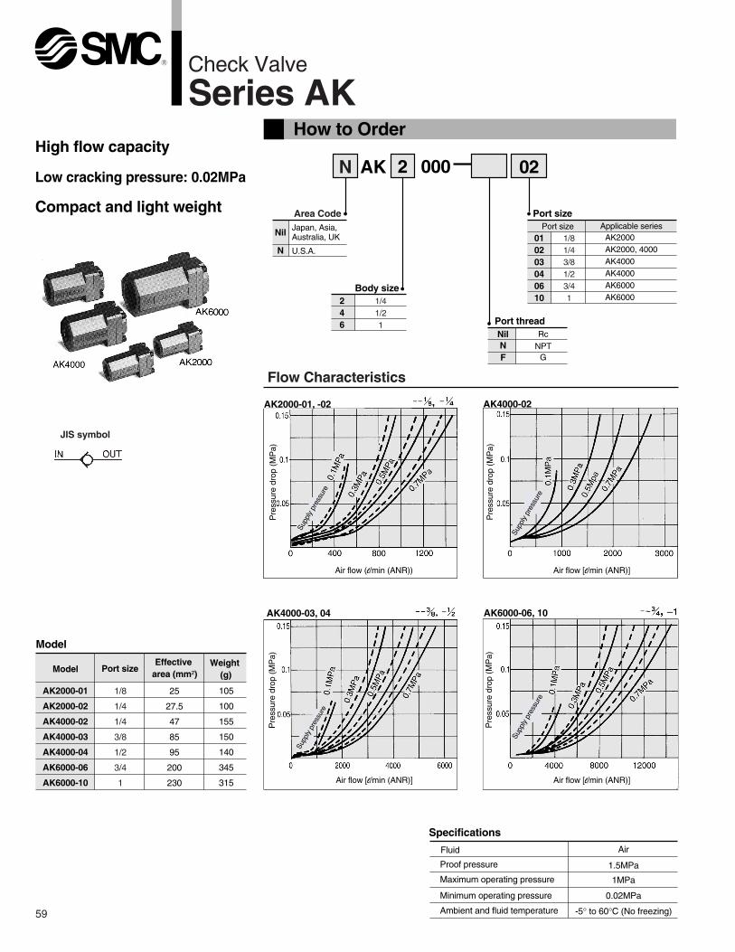
Specifications
Fluid
Proof pressure
Maximum operating pressure
Minimum operating pressure
Ambient and fluid temperature
Air
1.5MPa
1MPa
0.02MPa
-5° to 60°C (No freezing)
Air flow (l/min (ANR)) Air flow [l/min (ANR)]
Air flow [l/min (ANR)] Air flow [l/min (ANR)]
Pre
ssur
e dr
op (
MP
a)
Pre
ssur
e dr
op (
MP
a)
Pre
ssur
e dr
op (
MP
a)
Pre
ssur
e dr
op (
MP
a)
AK2000-01, -02 AK4000-02
AK4000-03, 04 AK6000-06, 10
Model
ModelEffective
area (mm²)Port size
Weight (g)
AK2000-01
AK2000-02
AK4000-02
AK4000-03
AK4000-04
AK6000-06
AK6000-10
25
27.5
47
85
95
200
230
105
100
155
150
140
345
315
Supp
ly p
ress
ure
High flow capacity
Low cracking pressure: 0.02MPa
Compact and light weight
JIS symbol
Supp
ly p
ress
ure
Flow Characteristics
Supp
ly p
ress
ure
Supp
ly p
ress
ure
1/41/21
59
1/8
1/4
1/4
3/8
1/2
3/4
1
1/81/43/81/23/41

Series AK
60
Construction
Dimensions
Component parts
Replacement parts
No.
No.
Description
Description
Material
MaterialPart No.
AK2000 AK4000 AK6000
q
w
e
r
t
y
u
Valve
Spring
O-ring
Ring
Seat ring
Cover
Body
POM
Stainless steel
NBR
NBR
Brass, NBR
Aluminum die casted Note 1)
Aluminum die casted Note 1)
19033
19037
19014
19015
19016
19013
19024
19025
19026
19023
20 x 17 x 1.5
Note 1) AK2000: Zinc alloy
AK2000 AK4000/6000
Model Port size L1 H�B
AK2000-01, 02
AK4000-02, 03, 04
AK6000-06, 10
50
67
95
25
36
50
22
36
50
Caution
1/8, 1/4
1/4, 3/8, 1/2
3/4, 1
Read carefully before handling.Refer to page 64 and 65 for Safety Instructions and common precautions on the products mentioned in this catalog, refer to page 66 through 68 for precautions for every series.
IN OUT IN OUT
IN OUT
H
�BL1
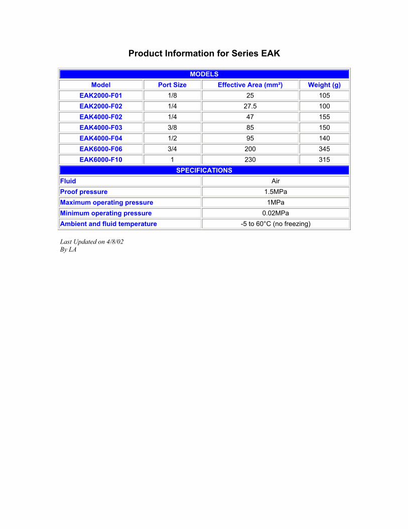
Product Information for Series EAK MODELS
Model Port Size Effective Area (mm²) Weight (g) EAK2000-F01 1/8 25 105 EAK2000-F02 1/4 27.5 100 EAK4000-F02 1/4 47 155 EAK4000-F03 3/8 85 150 EAK4000-F04 1/2 95 140 EAK6000-F06 3/4 200 345 EAK6000-F10 1 230 315
SPECIFICATIONS Fluid Air Proof pressure 1.5MPa Maximum operating pressure 1MPa Minimum operating pressure 0.02MPa Ambient and fluid temperature -5 to 60°C (no freezing) Last Updated on 4/8/02 By LA

1. Products mentioned in this catalog are not designed for the use as stop valve with zero air leakage. A certain amount of leakage is allowed in the product's specifi-cations.
Precautions
1. Check that the lock nut is tightened. A loose lock nut may cause actuator speed changes.
2. Confirm the degree of rotation of the needle valve. Products mentioned in this catalog are retainer type so that the needle is not removed completely. Over rotation will cause damage.
3. Do not use tools such as pliers to rotate the handle.It can cause idle rotation of the handle or damage.
4. Confirm air flow direction. Mounting backwards is dangerous, because the speed adjustment needle will not work and the actuator may lurch suddenly.
5. Adjust needle by opening the needle slowly after having closed it completely. Loose needle valves may cause unexpected sudden actuator extension. When needle valve is turned clockwise, it is closed and cylinder speed decreases. When needle valve is turned counter clockwise, it is open and cylinder speed increases.
6. Do not apply excessive force or shock to the body or fittings with an impact tool.It can cause damage or air leakage.
1. Confirm that PTFE can be used in application. PTFE powder (Polytetrafluoroethylene resin) is included in the seal material. Confirm if the use of it may cause any adverse effect in the system.
1. To install/remove the Flow Control Equipment, tighten/loosen at wrench flat B as close to the thread as possible using the appropriate wrench. Do not apply torque at other points as the product may be damaged. Rotate Body A manually for positioning after installation.
2. Do not use universal type fittings for applications involving continuous rotation. The fitting section may be damaged.
Series AS-F/FE/FG/FM
1. The tightening torque for pipe fittings is as shown in the table. As a rule, they should be tightened 2 to 3 turns with a tool after first tightening by hand. Be careful not to cause damage by over-tightening.
Male thread Suitable screw torque(N·m)
Hexagon widthacross flats
(mm)Adjustable spanner
nominal (mm)
M3
M510/32-UNF
1/8
1/4
3/8
1/2
1/4
1/6 turn afterhand tightening
7 to 9
12 to 14
22 to 24
28 to 30
4.5
8
14
17
21
24
—
100
150
200
200
200
1. Suitable screw torque for a hexagon lock nut is shown in the table below. For standard installation, turn 15 to 30° using tool, after fastening by hand. Pay attention not to over torque the product.
Suitable screw torque(N·m)
0.07
0.3
1
1.5
4
10
Body size
M3
M5
1/8
1/4
3/8
1/2
Selection
Mounting
Selection
Mounting
Tightening Torque
Lock Nut Tightening Torque
Warning
Warning
Warning
Warning
Caution
Caution
Flow Control Equipment PrecautionsBe sure to read before handling. Refer to pages 15-18-3 to 15-18-4 for Safety Instructions and Common Precautions on the products mentioned in this catalog, and refer to main text for more detailed precautions on every series.
15-8-6
15-8-7
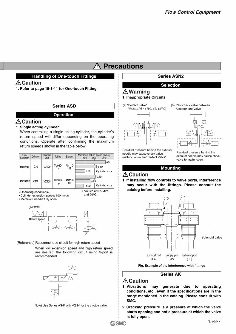
Flow Control Equipment
Precautions
1. Refer to page 15-1-11 for One-touch Fitting.
Handling of One-touch Fittings
1. Inappropriate Circuits
Selection
1. If installing flow controls to valve ports, interference may occur with the fittings. Please consult the catalog before installing.
Mounting
(a) “Perfect Valve” (VF66��, VS7-6-FPG, VS7-8-FPG)
(b) Pilot check valve between Actuator and Valve
Series ASN2
Residual pressure behind the exhaust needle may cause check valve malfunction in the “Perfect Valve”.
Residual pressure behind theexhaust needle may cause check valve to malfunction.
Solenoid valve
Exhaust port(EA)
Supply port(P)
Exhaust port(EB)
Fig. Example of the interference with fittings
Series AK
1. Vibrations may generate due to operating conditions, etc., even if the specifications are in the range mentioned in the catalog. Please consult with SMC.
2. Cracking pressure is a pressure at which the valve starts opening and not a pressure at which the valve is fully open.
Series ASD
1. Single acting cylinderWhen controlling a single acting cylinder, the cylinder’s return speed will differ depending on the operating conditions. Operate after confirming the maximum return speeds shown in the table below.
<Operating conditions>• Cylinder extension speed: 100 mm/s• Meter-out needle fully open
Note) Use Series AS-F with -X214 for the throttle valve.
SpeedController Cylinder Solenoid
valve Tubing Silencer Maximum return speed (mm/s)100 200 300
ASD230F CJ2 VJ500 TU06041 m
AN110-01
ASD330F CM2 VZ500 TU06041 m
AN110-01
100 mm/s
Operation
Return speed
Cylinder size
ø16
ø10
ø6
ø20
ø25
ø32
Cylinder size
∗ Values at 0.5 MPa and 20°C.
(Reference) Recommended circuit for high return speed
When low extension speed and high return speed are desired, the following circuit using 3-port is recommended.
Warning
Caution
Caution
Caution
Caution