Chapter 6 Fundamentals of Electronics and Computers.
66
Chapter 6 Fundamentals of Electronics and Computers
-
Upload
franklin-wright -
Category
Documents
-
view
252 -
download
4
Transcript of Chapter 6 Fundamentals of Electronics and Computers.
Chapter 6
Fundamentals of Electronics and Computers
Objectives (1 of 4)
• Outline some of the developmental history of electronics.
• Describe how an electrical signal can be used to transmit information.
• Define the term pulse width modulation.
• Define the principle of operation of N- and P-type semiconductors.
• Outline the operating principles and applications of diodes.
Objectives (2 of 4)
• Describe the construction and operation of a typical transistor.
• Describe what is meant by the optical spectrum.
• Identify some commonly used optical components used in electronic circuitry.
• Explain what is meant by an integrated circuit and outline its application in on-board vehicle electronics.
• Define the role of gates in electronic circuits.
Objectives (3 of 4)
• Describe the operating modes of some common gates used in electrical circuits including AND, OR, and NOT gates.
• Interpret a truth table that defines the outcomes of gates in an electrical circuit.
• Explain why the binary numeric system is used in computer electronics.
• Define the role of an electronic control module in an electronic management system.
Objectives (4 of 4)
• Outline the distinct stages of a computer processing cycle.
• Describe the data retention media used in vehicle ECMs.
• Demonstrate an understanding of input circuits on a vehicle electronic system.
• Troubleshoot a potentiometer-type TPS.• Describe the operating principles of the
VORAD collision warning system.
Using Electronic Signals (1 of 3)
• Electronic signals used to manage information are generally low voltage/low current circuits.– They may be classified as:
• Analog
• Digital
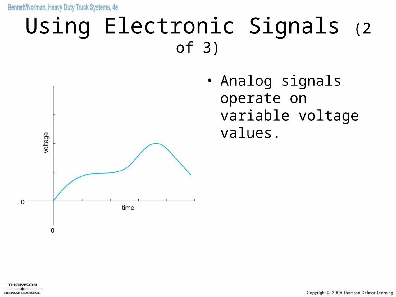
Using Electronic Signals (2 of 3)
• Analog signals operate on variable voltage values.
Using Electronic Signals (3 of 3)
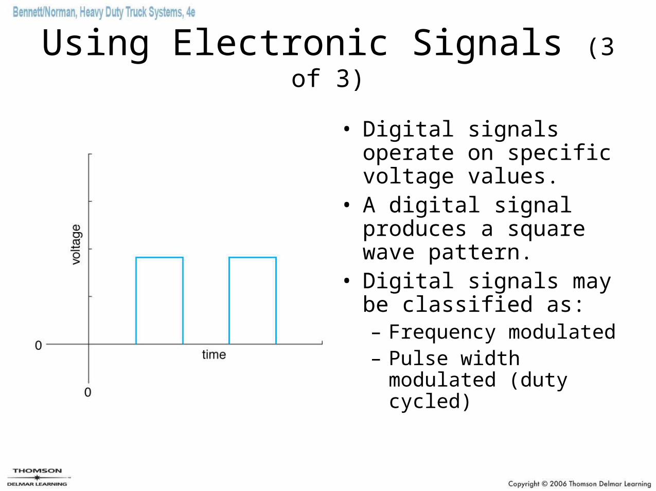
• Digital signals operate on specific voltage values.
• A digital signal produces a square wave pattern.
• Digital signals may be classified as:– Frequency modulated– Pulse width modulated
(duty cycled)
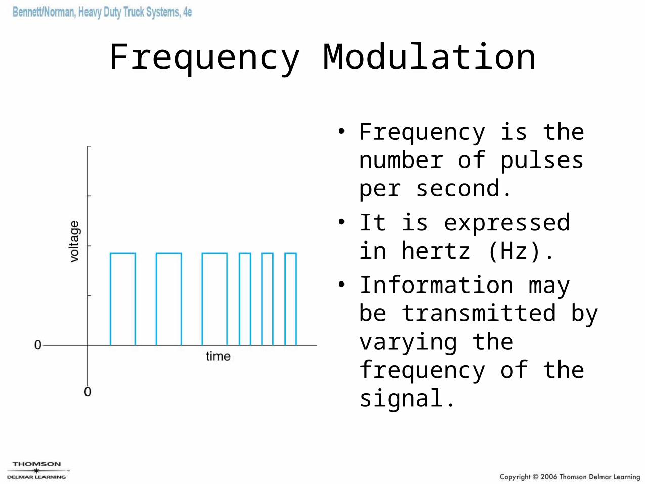
Frequency Modulation
• Frequency is the number of pulses per second.
• It is expressed in hertz (Hz).
• Information may be transmitted by varying the frequency of the signal.
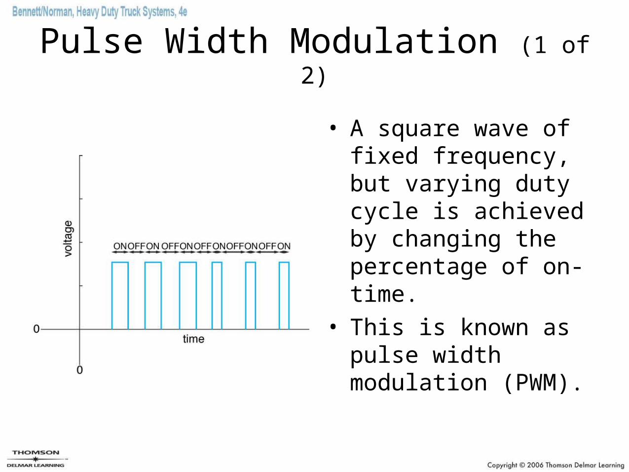
Pulse Width Modulation (1 of 2)
• A square wave of fixed frequency, but varying duty cycle is achieved by changing the percentage of on-time.
• This is known as pulse width modulation (PWM).
Pulse Width Modulation (2 of 2)
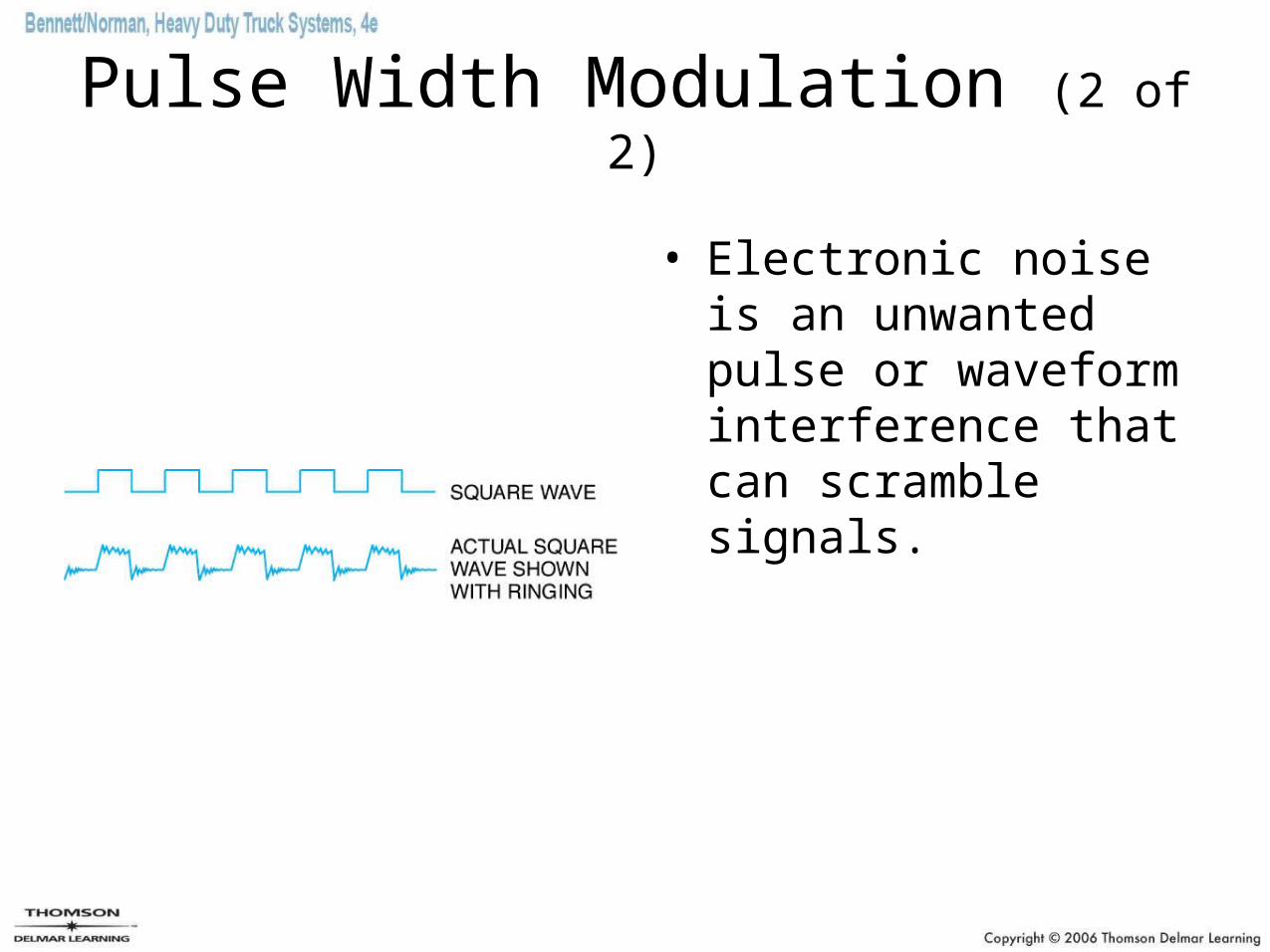
• Electronic noise is an unwanted pulse or waveform interference that can scramble signals.
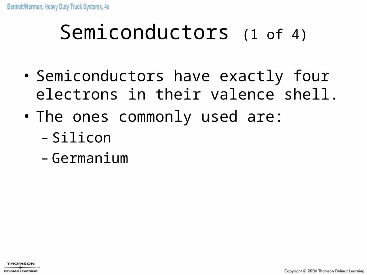
Semiconductors (1 of 4)
• Semiconductors have exactly four electrons in their valence shell.
• The ones commonly used are:– Silicon– Germanium
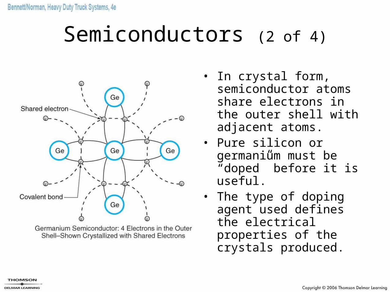
Semiconductors (2 of 4)
• In crystal form, semiconductor atoms share electrons in the outer shell with adjacent atoms.
• Pure silicon or germanium must be “doped” before it is useful.
• The type of doping agent used defines the electrical properties of the crystals produced.
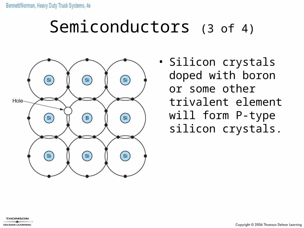
Semiconductors (3 of 4)
• Silicon crystals doped with boron or some other trivalent element will form P-type silicon crystals.
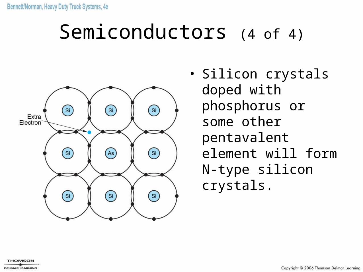
Semiconductors (4 of 4)
• Silicon crystals doped with phosphorus or some other pentavalent element will form N-type silicon crystals.
Diodes (1 of 3)
• Diodes have two terminals.
• A diode is used in electrical circuitry as a sort of one way check valve which conducts electricity in one direction and blocks it in the opposite direction.
• When a diode is forward-biased, it should conduct electricity.
• When a diode is reverse-biased, it should not conduct electricity.
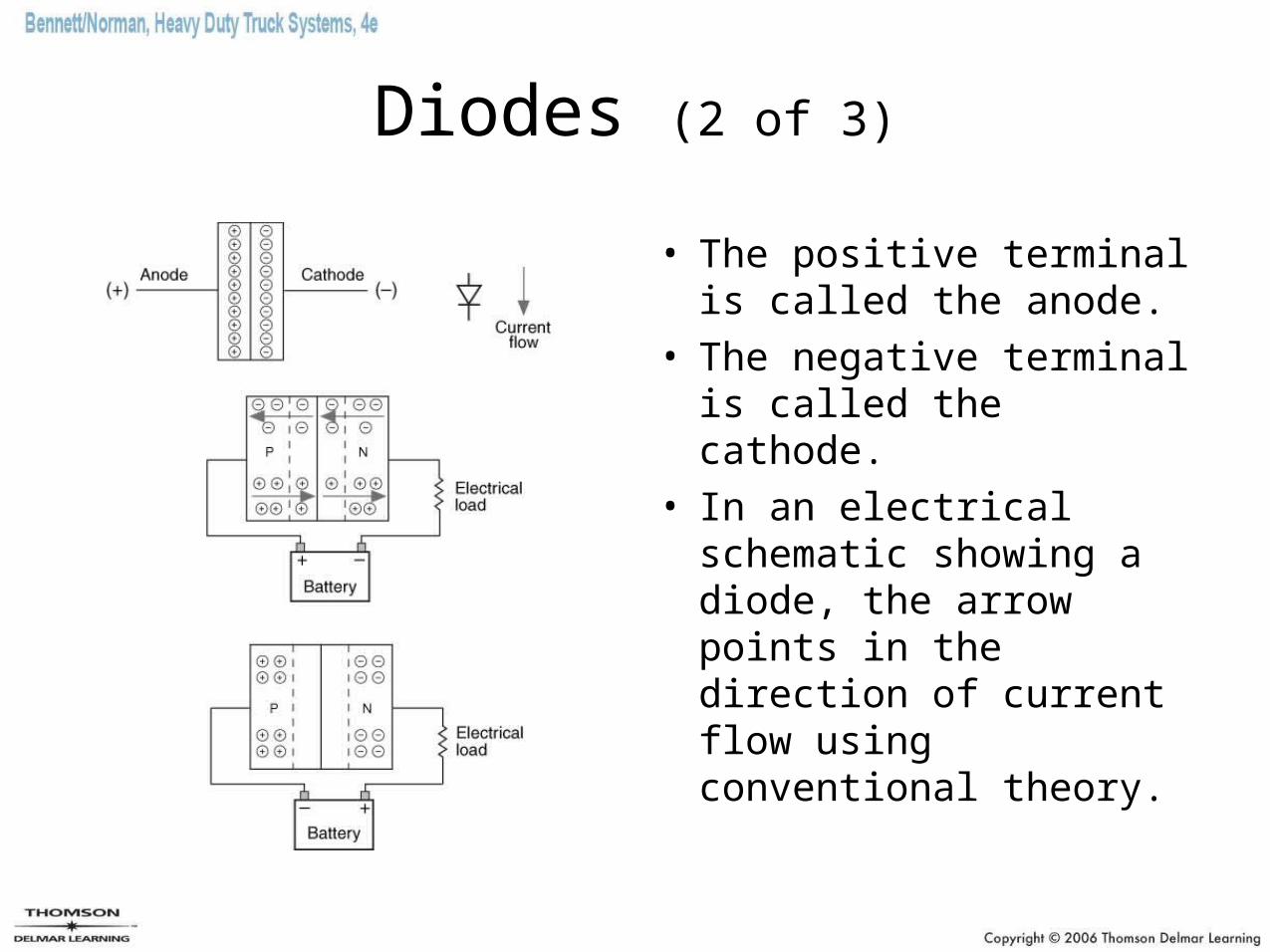
Diodes (2 of 3)
• The positive terminal is called the anode.
• The negative terminal is called the cathode.
• In an electrical schematic showing a diode, the arrow points in the direction of current flow using conventional theory.
Diodes (3 of 3)
• Types of diodes– Small signal diodes– Power rectifier diodes– Zener diodes– Light-emitting diodes (LEDs)– Photo diodes
Transistors (1 of 10)
• Transistors are three-terminal semiconductor chips that are used extensively in electronic circuits primarily for switching and amplification.
• Transistors are active circuit elements capable of amplifying or transforming a signal level.
• A transistor consists of two P-N junctions.
• A transistor functions in an electronic circuit in much the same manner that a relay functions in an electrical circuit.
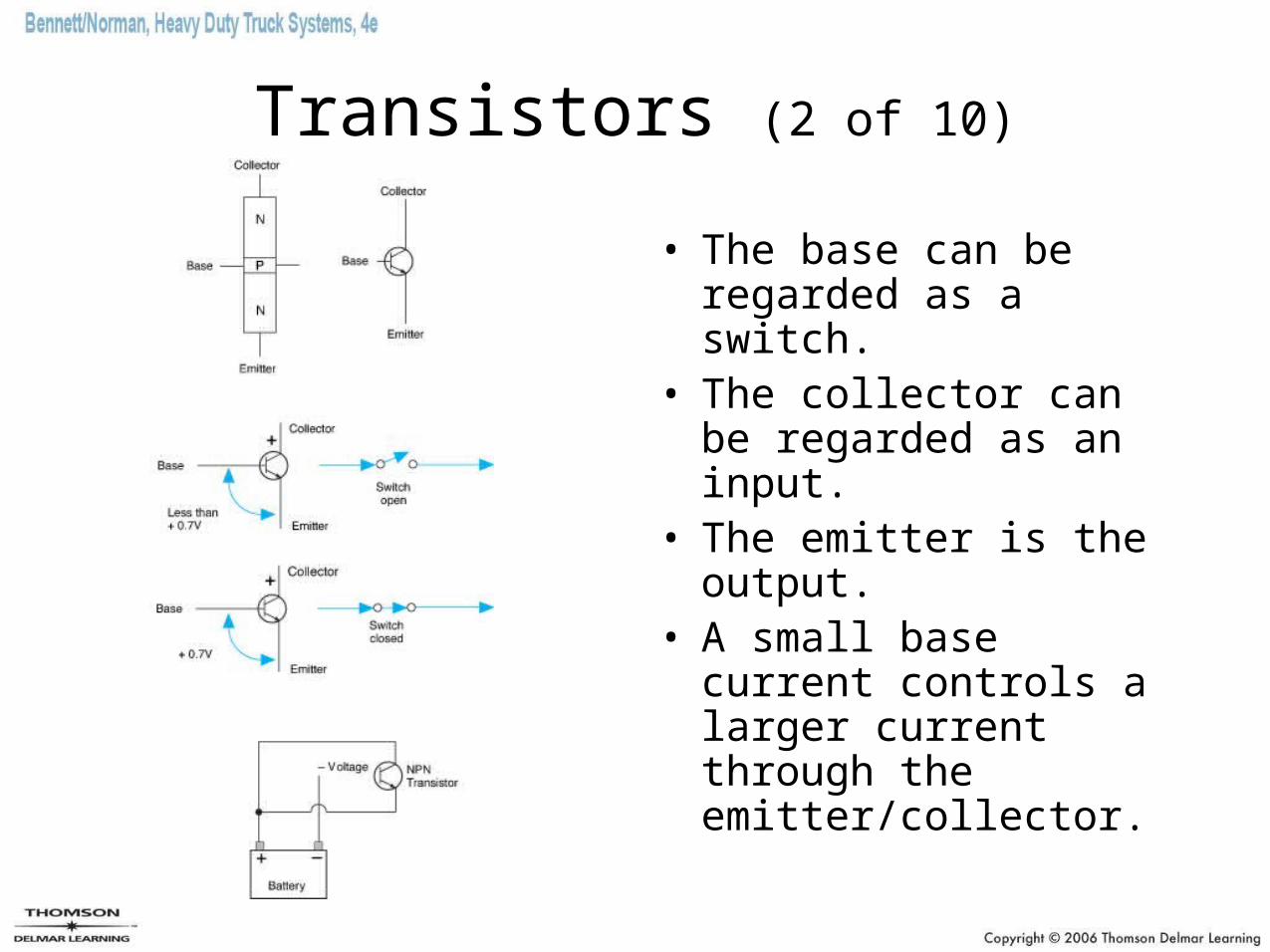
Transistors (2 of 10)
• The base can be regarded as a switch.
• The collector can be regarded as an input.
• The emitter is the output.
• A small base current controls a larger current through the emitter/collector.
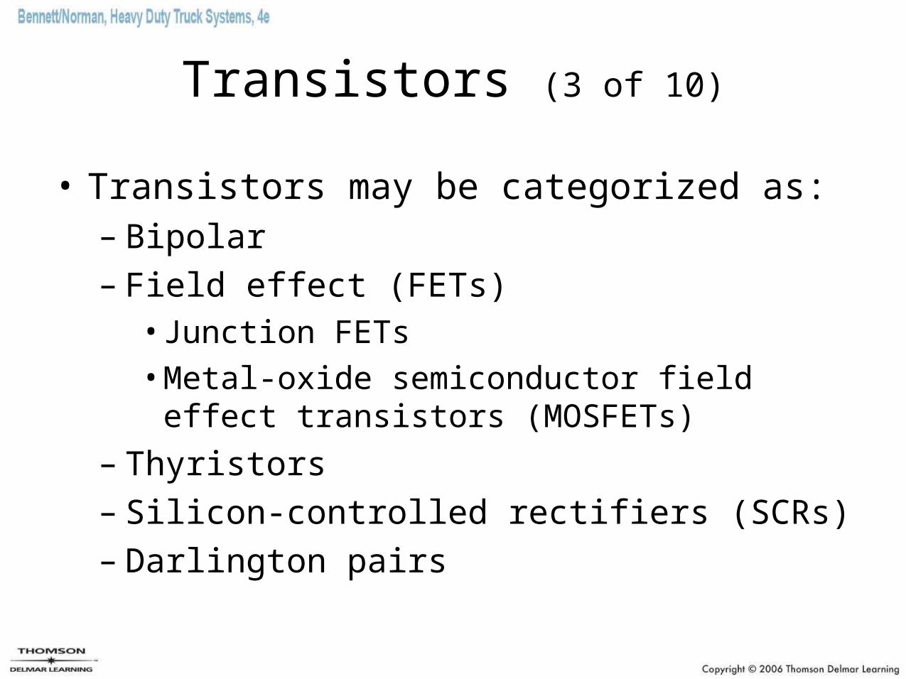
Transistors (3 of 10)
• Transistors may be categorized as:– Bipolar– Field effect (FETs)
• Junction FETs
• Metal-oxide semiconductor field effect transistors (MOSFETs)
– Thyristors– Silicon-controlled rectifiers (SCRs)– Darlington pairs
Transistors (4 of 10)
• Bipolar transistors– The base emitter junctions will not conduct
until the forward bias voltage exceeds ± 0.6V.– Excessive current flow through a transistor will
cause it to overheat or fail.– Excessive voltage can destroy the
semiconductor crystal media. – A small base current can be used to control a
much larger collector current.
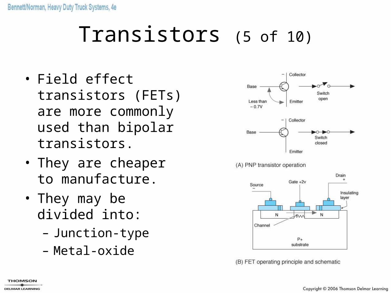
Transistors (5 of 10)
• Field effect transistors (FETs) are more commonly used than bipolar transistors.
• They are cheaper to manufacture.
• They may be divided into:– Junction-type
– Metal-oxide
Transistors (6 of 10)
• JFETs– JFET gate resistance is very high, so the
device has almost no effect on external components connected to the gate.
– The gate and channel form a “diode,” and as long as the input signal “reverse biases” this diode, the gate will show high resistance.
Transistors (7 of 10)
• MOSFETs– They have become the most important type of
transistor in microcomputer applications.– Thousands can be photo-infused onto minute
silicon wafers.– They can act both as a switch and as variable
resistors.– They can be switches at very high speeds.
Transistors (8 of 10)
• Thyristors– Thyristors are solid-state switches.– They are only capable of switching.– They fall into two classes depending upon
whether they switch AC or DC current.
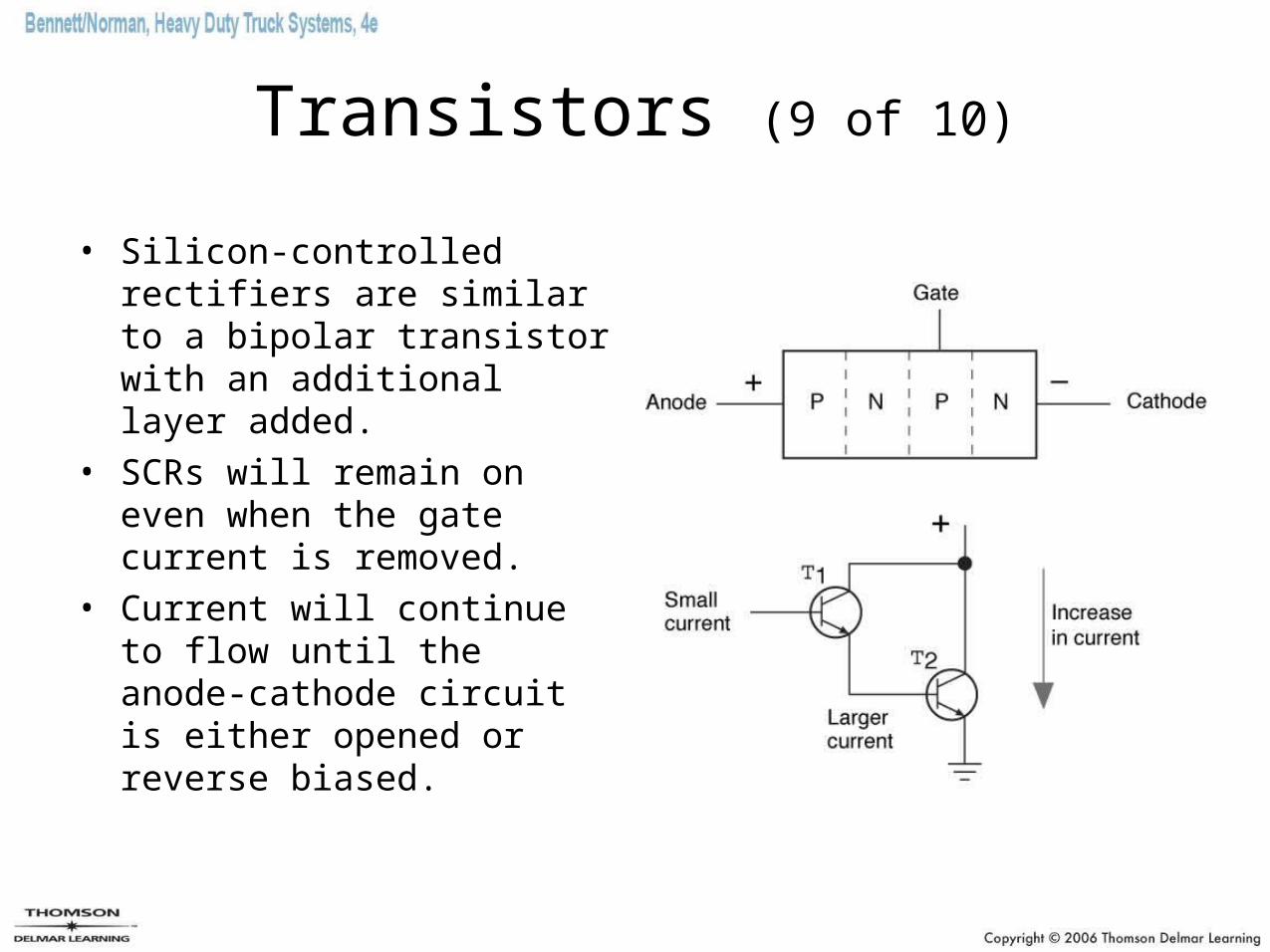
Transistors (9 of 10)
• Silicon-controlled rectifiers are similar to a bipolar transistor with an additional layer added.
• SCRs will remain on even when the gate current is removed.
• Current will continue to flow until the anode-cathode circuit is either opened or reverse biased.
Transistors (10 of 10)
• Darlington pairs– A pair of transistors are connected so that the emitter
of one supplies the base of the other through which a much larger current flows.
– This provides signal amplification.
– They are used extensively in computer control systems and ignition modules.
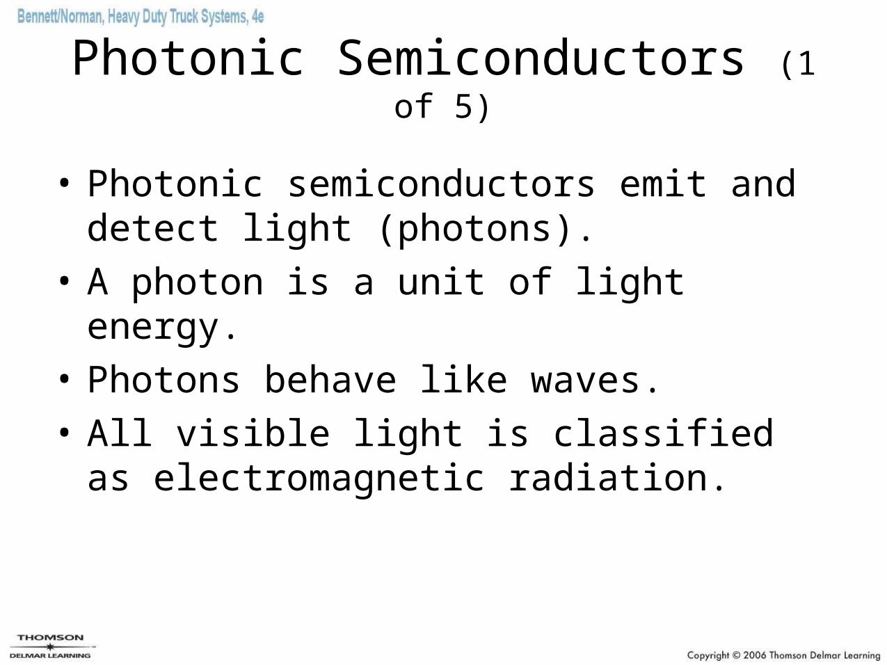
Photonic Semiconductors (1 of 5)
• Photonic semiconductors emit and detect light (photons).
• A photon is a unit of light energy.
• Photons behave like waves.
• All visible light is classified as electromagnetic radiation.
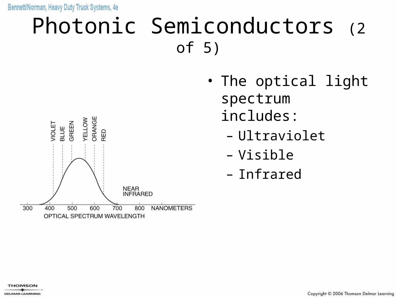
Photonic Semiconductors (2 of 5)
• The optical light spectrum includes:– Ultraviolet
– Visible
– Infrared
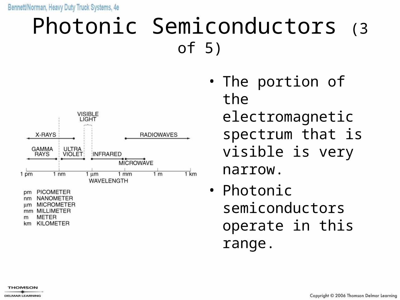
Photonic Semiconductors (3 of 5)
• The portion of the electromagnetic spectrum that is visible is very narrow.
• Photonic semiconductors operate in this range.
Photonic Semiconductors (4 of 5)
• The importance of optical components in the electronic age is increasing.
• Data signaling functions will be removed from hard-wired buses and will be performed using fiber optics.
• Optical components may conduct, refract, or modify light.
• The use of optical components in vehicle technology is increasing.
Photonic Semiconductors (5 of 5)
• Optical components:– Filters– Reflectors– Beam splitters– Lenses– Optical fibers– Solar cells
Testing Semiconductors (1 of 2)
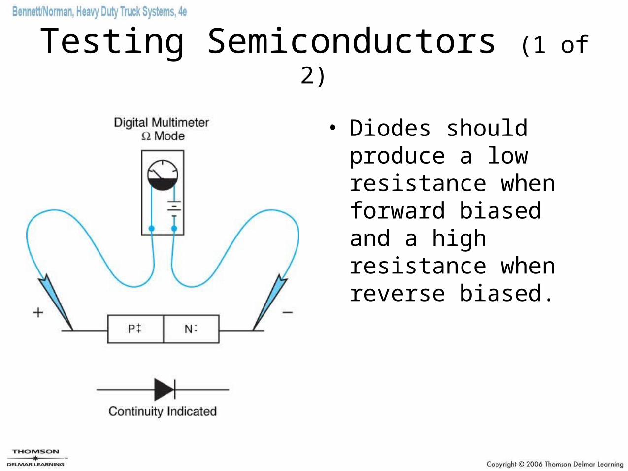
• Diodes should produce a low resistance when forward biased and a high resistance when reverse biased.
Testing Semiconductors (2 of 2)
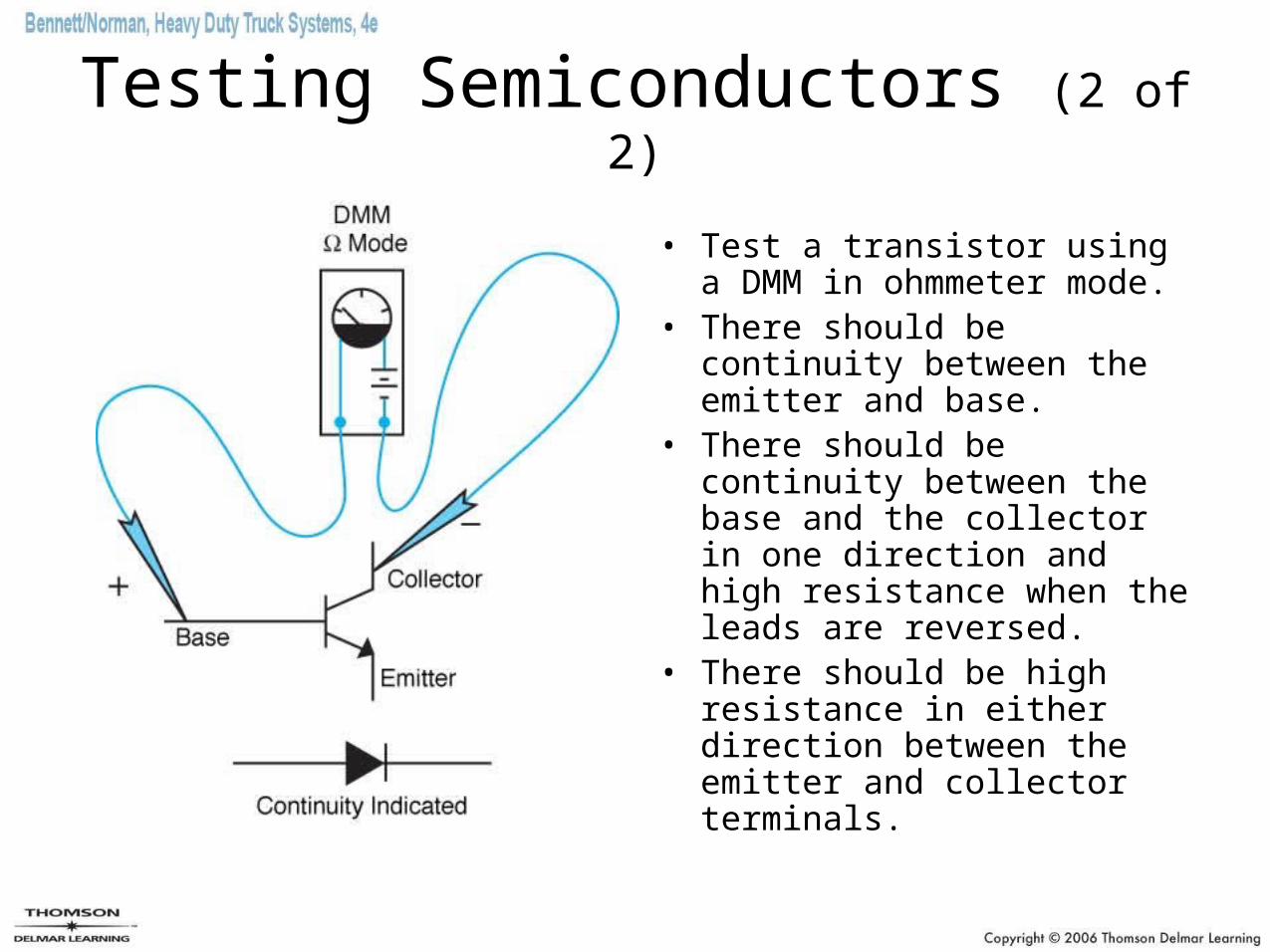
• Test a transistor using a DMM in ohmmeter mode.
• There should be continuity between the emitter and base.
• There should be continuity between the base and the collector in one direction and high resistance when the leads are reversed.
• There should be high resistance in either direction between the emitter and collector terminals.
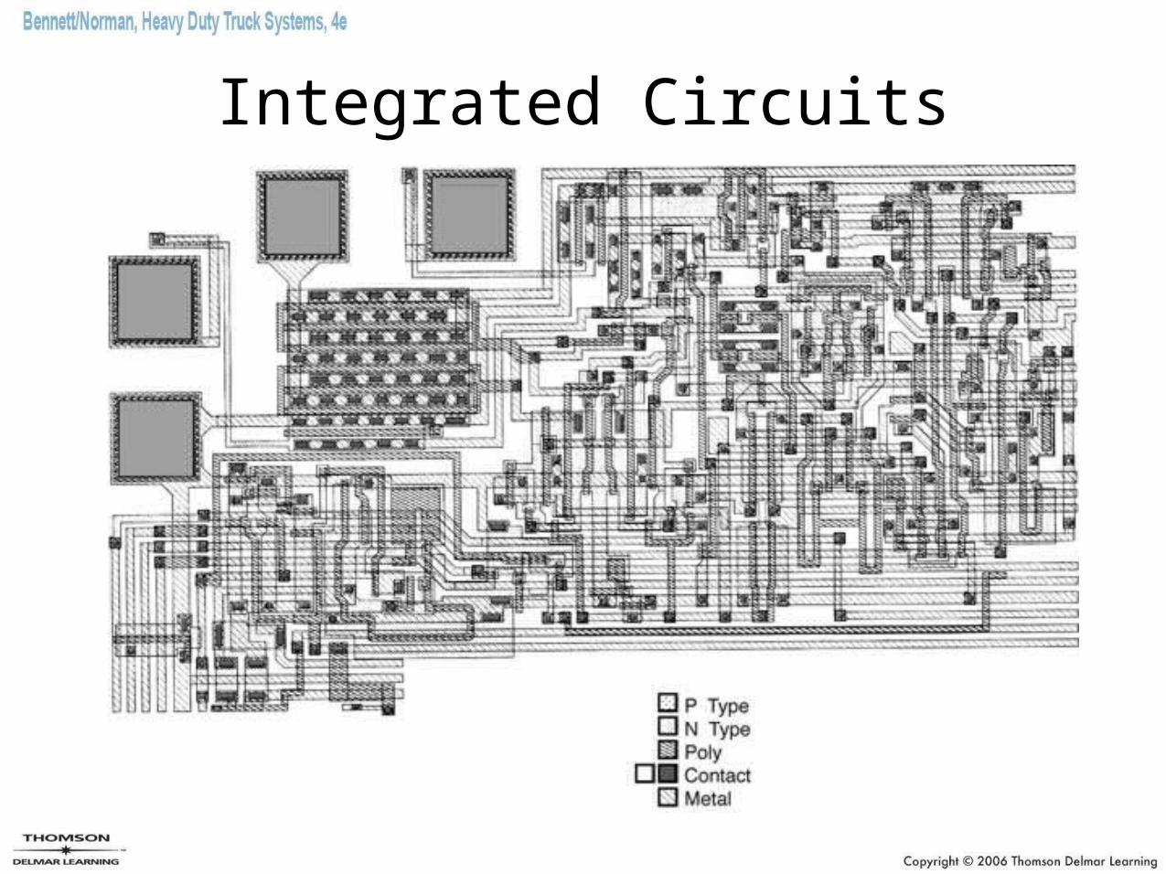
Integrated Circuits
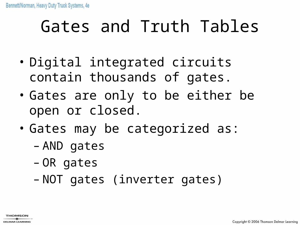
Gates and Truth Tables
• Digital integrated circuits contain thousands of gates.
• Gates are only to be either be open or closed.
• Gates may be categorized as:– AND gates– OR gates– NOT gates (inverter gates)
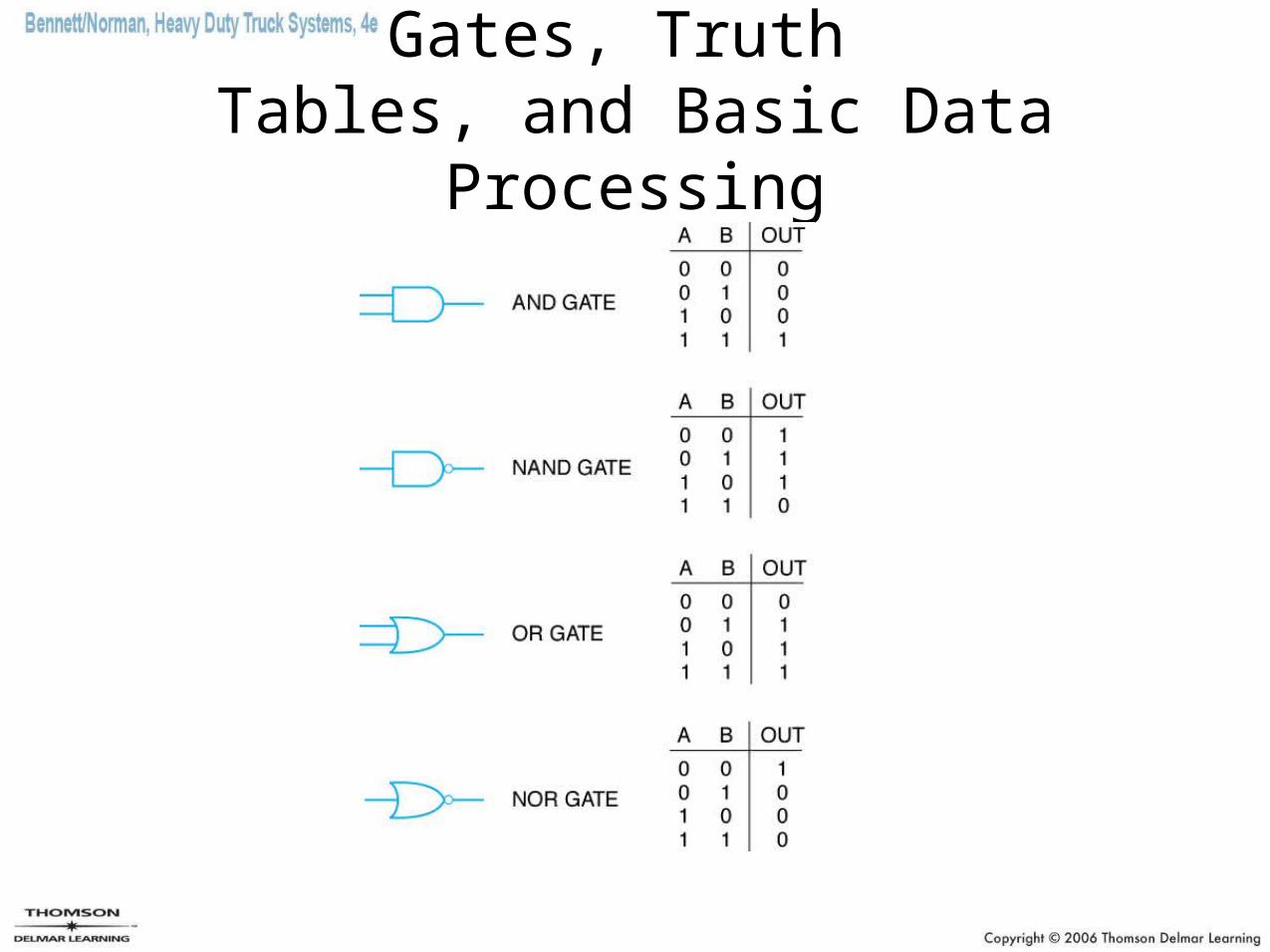
Gates, Truth Tables, and Basic Data Processing
Binary System Basics
• The binary system is an arithmetic system with only two digits, 1 and 0.
• The binary system is used in computers because it directly corresponds to the on or off states of switches.
• Digital electronic data is stored in binary code.
• Digital signals may be transmitted:– Serial data link
– Parallel data link
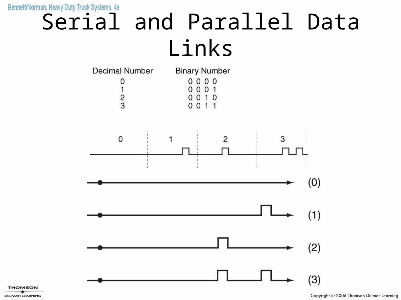
Serial and Parallel Data Links
Microprocessors (1 of 2)
• A microprocessor is a solid-state chip containing many hundred of thousands of gates per square inch.
• The microprocessor is the core of both personal and vehicular computer systems
• On-board computers are referred to as ECMs.
• Truck technicians must have a basic understanding of both personal computers and vehicle ECMs.
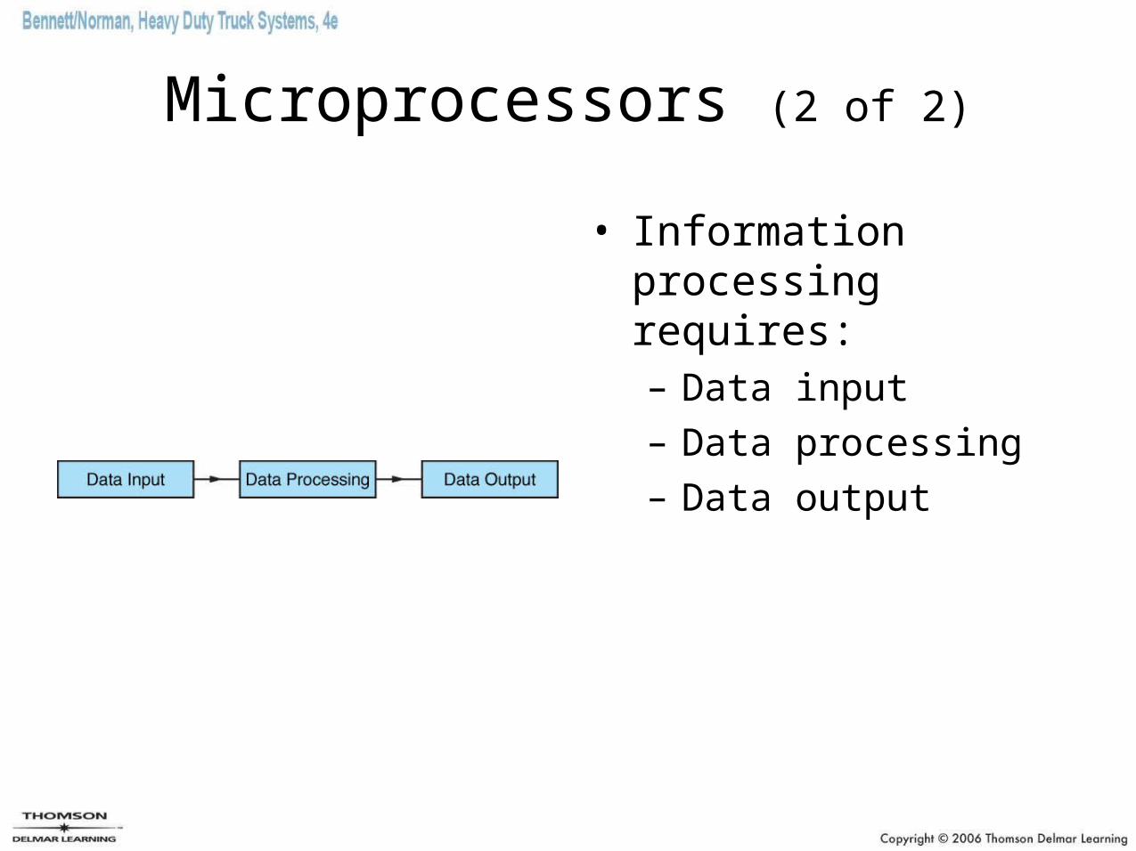
Microprocessors (2 of 2)
• Information processing requires:– Data input
– Data processing
– Data output
Data Input
• Most data input devices are sensors.– Thermistors– Variable capacitance sensor (pressure)– Piezo-resistive sensor– Potentiometers– Hall-effect sensors– Induction pulse generator– Switches
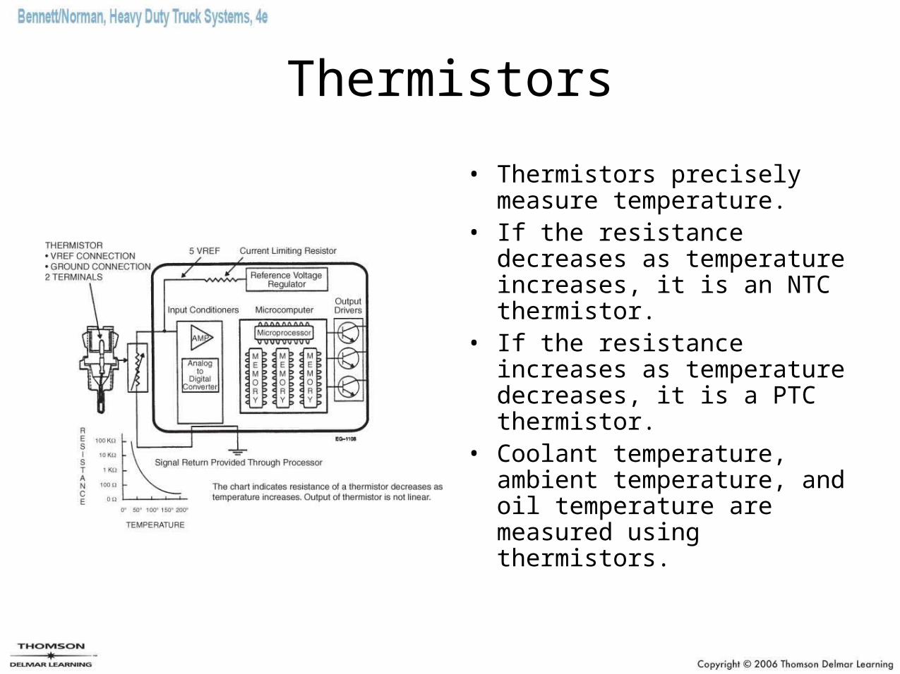
Thermistors
• Thermistors precisely measure temperature.
• If the resistance decreases as temperature increases, it is an NTC thermistor.
• If the resistance increases as temperature decreases, it is a PTC thermistor.
• Coolant temperature, ambient temperature, and oil temperature are measured using thermistors.
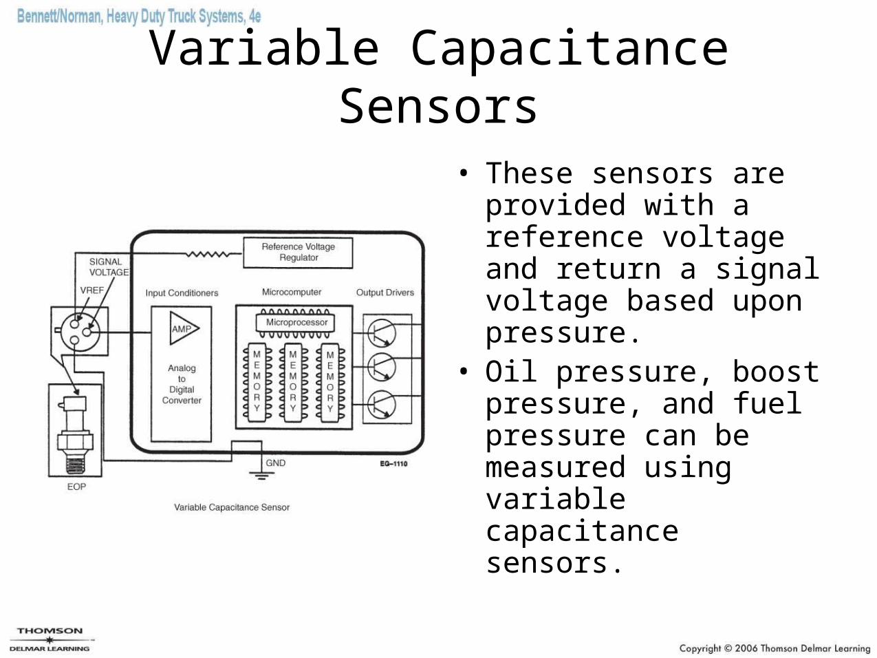
Variable Capacitance Sensors
• These sensors are provided with a reference voltage and return a signal voltage based upon pressure.
• Oil pressure, boost pressure, and fuel pressure can be measured using variable capacitance sensors.
Piezo-Resistive Pressure Sensor
• Piezo-resistive sensors are sometimes referred to as wheatstone bridges.
• A doped silicon chip is formed in a diaphragm shape with the center much thinner. A set of sensing resistors are attached around the perimeter and measure the amount of flexing in response to pressure.
• An electrical signal proportional to pressure is thus obtained.
• Manifold pressure may be measured using piezo-resistive sensors.
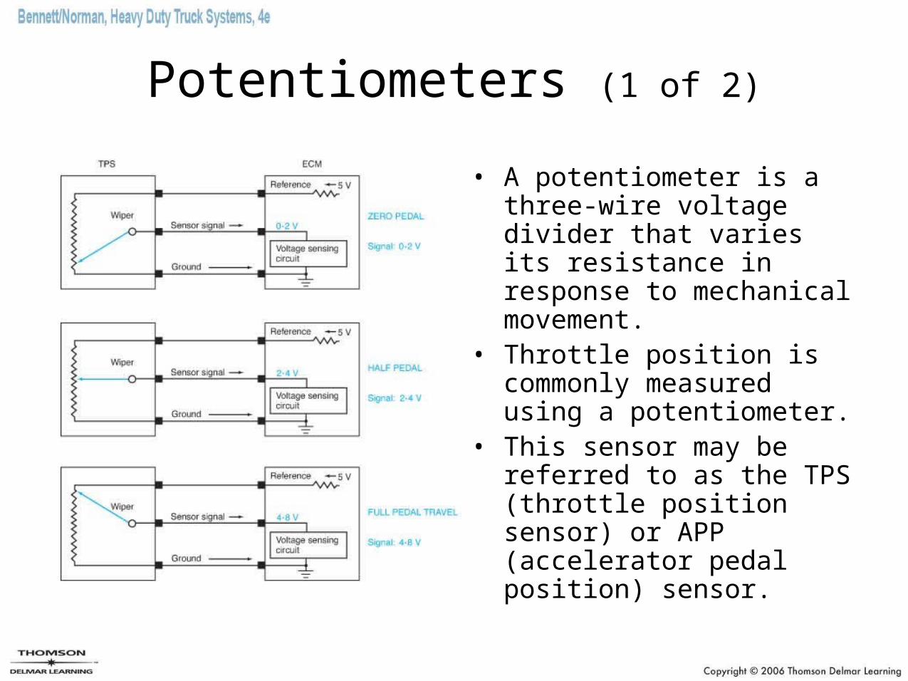
Potentiometers (1 of 2)
• A potentiometer is a three-wire voltage divider that varies its resistance in response to mechanical movement.
• Throttle position is commonly measured using a potentiometer.
• This sensor may be referred to as the TPS (throttle position sensor) or APP (accelerator pedal position) sensor.
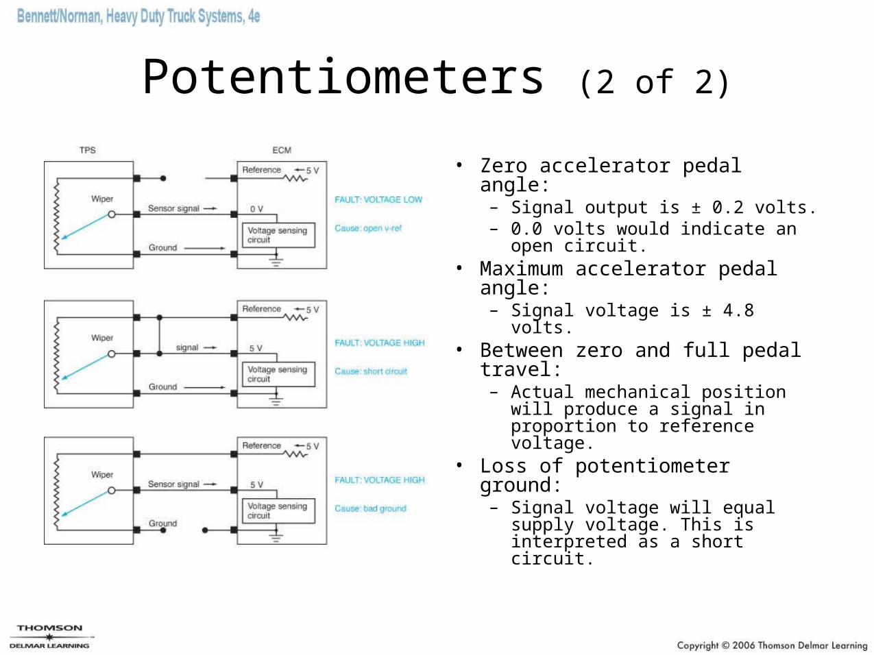
Potentiometers (2 of 2)
• Zero accelerator pedal angle: – Signal output is ± 0.2 volts. – 0.0 volts would indicate an
open circuit.• Maximum accelerator pedal
angle: – Signal voltage is ± 4.8 volts.
• Between zero and full pedal travel: – Actual mechanical position will
produce a signal in proportion to reference voltage.
• Loss of potentiometer ground: – Signal voltage will equal
supply voltage. This is interpreted as a short circuit.
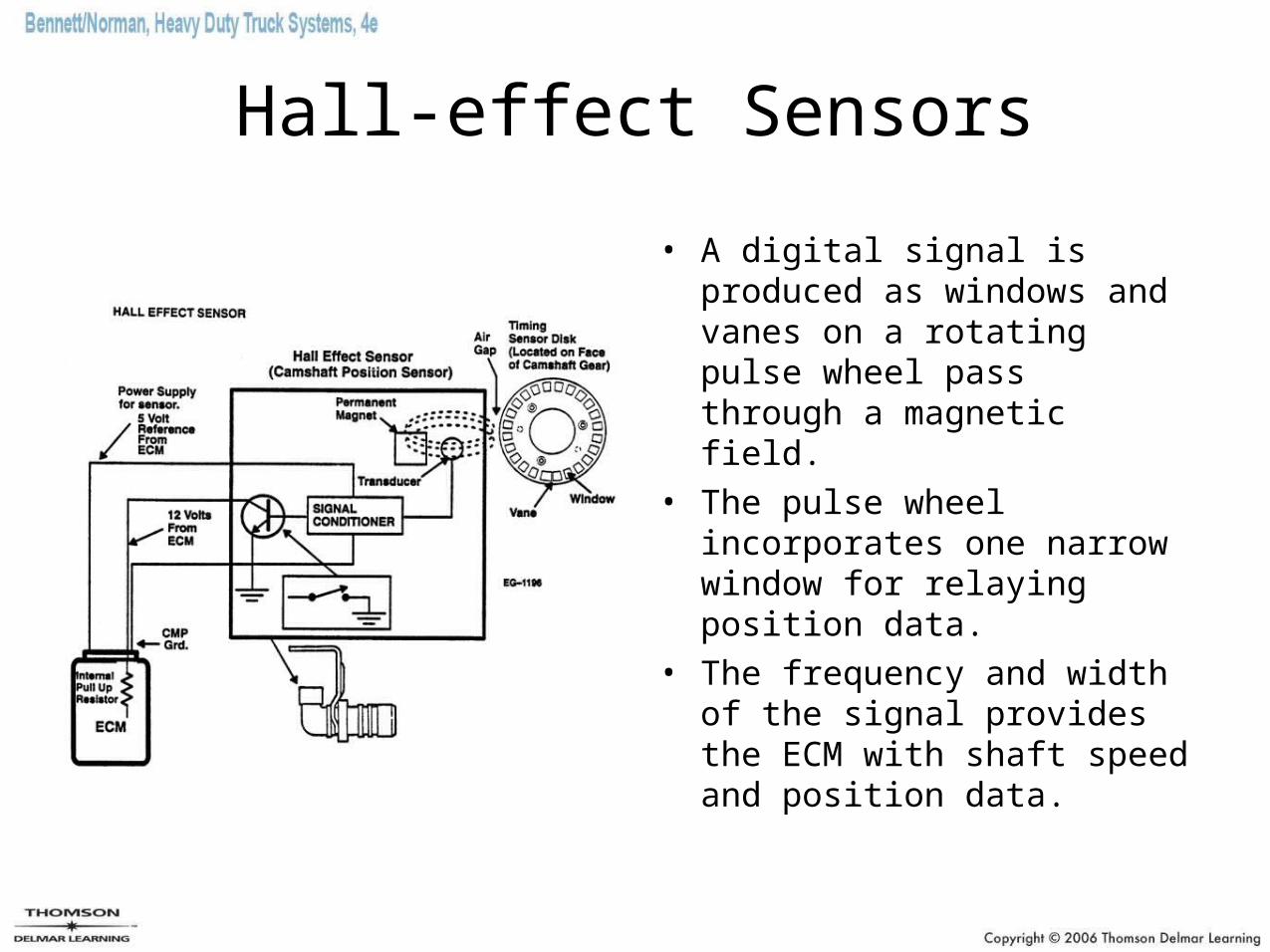
Hall-effect Sensors
• A digital signal is produced as windows and vanes on a rotating pulse wheel pass through a magnetic field.
• The pulse wheel incorporates one narrow window for relaying position data.
• The frequency and width of the signal provides the ECM with shaft speed and position data.
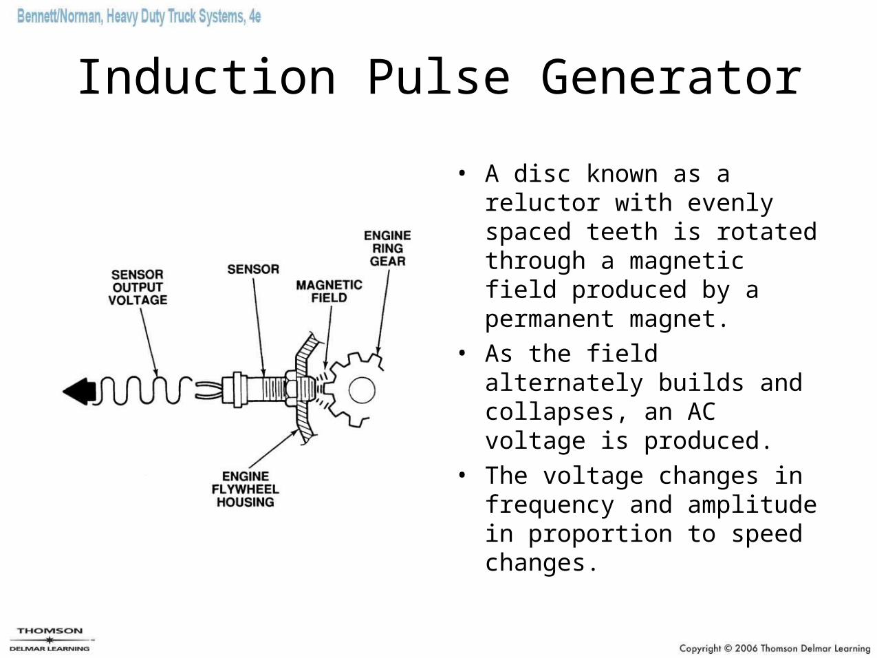
Induction Pulse Generator
• A disc known as a reluctor with evenly spaced teeth is rotated through a magnetic field produced by a permanent magnet.
• As the field alternately builds and collapses, an AC voltage is produced.
• The voltage changes in frequency and amplitude in proportion to speed changes.
Switches
• Switches produce a digital signal by being either open or closed.
• Toggle switches and coolant level sensors are examples of switches used as sensors.
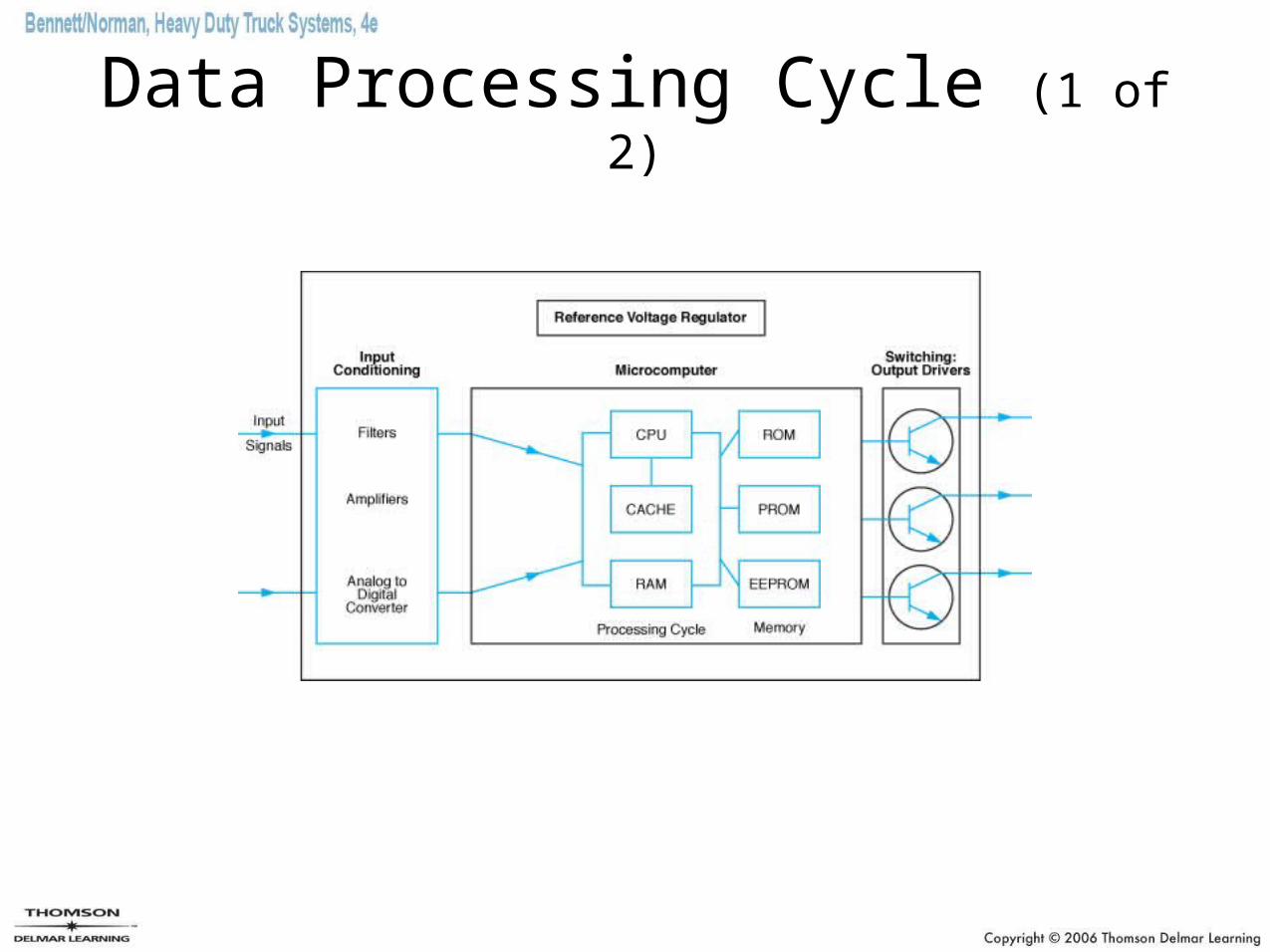
Data Processing Cycle (1 of 2)
Data Processing Cycle (2 of 2)
• Functions of the ECM– Uses a CPU to clock and manage the processing
cycle– Arithmetic logic unit (ALU) performs numeric
calculations– Contains in memory banks the data required to
manage the system– Conditions the processor circuit voltage– Manages the reference signal– Converts analog input data into a digital format using
an ADC (analog to digital converter)– Converts digital output to analog voltages required to
actuate electrical components
Outputs
• The results of data processing are converted into action by switching units (drivers) and actuators.
• Examples of actuators are solenoids, relays, lights, and displays.
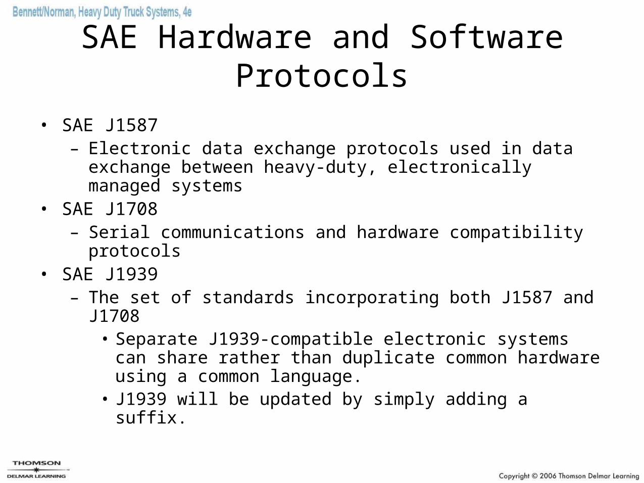
SAE Hardware and Software Protocols
• SAE J1587– Electronic data exchange protocols used in data exchange
between heavy-duty, electronically managed systems• SAE J1708
– Serial communications and hardware compatibility protocols• SAE J1939
– The set of standards incorporating both J1587 and J1708• Separate J1939-compatible electronic systems can share
rather than duplicate common hardware using a common language.
• J1939 will be updated by simply adding a suffix.
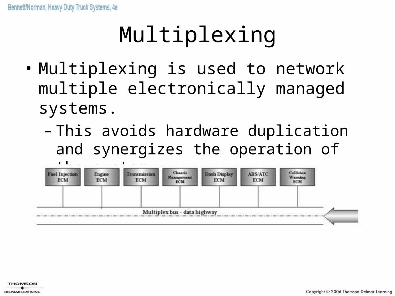
Multiplexing
• Multiplexing is used to network multiple electronically managed systems.– This avoids hardware duplication and
synergizes the operation of the system.
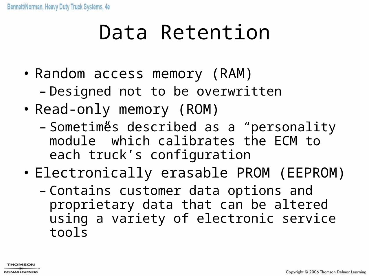
Data Retention
• Random access memory (RAM)– Designed not to be overwritten
• Read-only memory (ROM)– Sometimes described as a “personality
module” which calibrates the ECM to each truck’s configuration
• Electronically erasable PROM (EEPROM)– Contains customer data options and
proprietary data that can be altered using a variety of electronic service tools
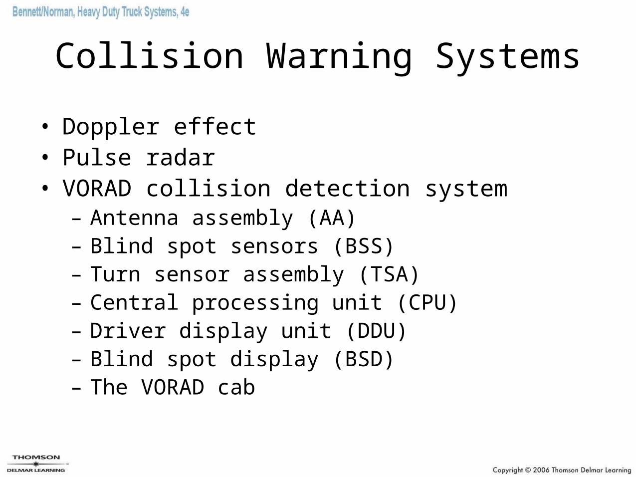
Collision Warning Systems
• Doppler effect• Pulse radar• VORAD collision detection system
– Antenna assembly (AA)– Blind spot sensors (BSS)– Turn sensor assembly (TSA)– Central processing unit (CPU)– Driver display unit (DDU)– Blind spot display (BSD)– The VORAD cab
Summary (1 of 8)
• Data can be transmitted electronically by means of electrical waveforms.
• Semiconductors are by definition elemental materials with four electrons in their outer shells.
• Silicon is the most commonly used semiconductor material.
• Semiconductors must be doped to provide them with the electrical properties that can make them useful as electronic components.
• After doping, semiconductor crystals may be classified as having N or P electrical properties.
Summary (2 of 8)
• Diodes are two-terminal semiconductors that often function as a sort of electrical one-way check valve.
• Zener diodes are commonly used in vehicle electronic systems.– They act as a voltage-sensitive switch in a circuit.
• Transistors are three-terminal semiconductor chips.
• Transistors can be generally grouped into bipolar and field effect types.
Summary (3 of 8)
• Essentially, a transistor is a semiconductor sandwich with the middle layer acting as a control gate. A small current flow through the base-emitter will ungate the transistor and permit a much larger emitter-collector current flow.
• Many different types of transistors are used in vehicle electronic circuits, but their roles are primarily concerned with switching and amplification.
• The optical spectrum includes ultraviolet, visible, and infrared radiation.
Summary (4 of 8)
• Optical components conduct, reflect, refract, or modify light. Fiber optics are being used increasingly in vehicle electronics, as are optical components.
• Integrated circuits consist of resistors, diodes, and transistors arranged in a circuit on a chip of silicon.
• A common integrated circuit chip package used in computer and vehicle electronic systems is a DIP with either 14 or 16 terminals.
• Many different chips with different functions are often arranged on a primary circuit board, also known as a motherboard.
Summary (5 of 8)
• Gates are switched controls that channel flows of data through electronic circuitry.
• AND, OR, and NOT gates are three commonly used means of producing an outcome based on the switching status of components in the gate circuit.
• The binary numeric system is a two-digit arithmetic system that is often used in computer electronics because it directly corresponds to the on or off states of switches and circuits.
• A bit is the smallest piece of data that a computer can manipulate. It has the ability to show one of two states, either on or off.
• A byte consists of 8 bits.
Summary (6 of 8)
• A byte of data can represent up to 256 pieces of coded data. • Almost all current on-highway trucks use computers to manage
the engine and usually other chassis systems as well. • A truck with multiple ECM-managed systems can network them
using a chassis data bus; this is known as multiplexing. • A vehicle ECM information processing cycle comprises three
stages: data input, data processing, and outputs. • RAM or main memory is electronically retained and therefore
volatile.
Summary (7 of 8)
• The master program for system management is usually written to ROM.
• PROM data is used to qualify the ROM data to a specific chassis application.
• Some OEMs describe their PROM component as a personality module.
• EEPROM provides an ECM with a read/write/erase memory component.
• Multiplexing is the term used to describe a system where two or more ECMs are networked to reduce input hardware and optimize vehicle operation.
Summary (8 of 8)
• Input data may be categorized as command data and system monitoring data.
• A potentiometer is a common input component: It is a three-terminal voltage divider.
• Collision warning systems (CWS) use a combination of Doppler radar and motion sensors to alert drivers to imminent collision hazards.
• A CWS such as VORAD processes data received from radar and microwave motion/proximity sensors into three categories of warning based on programmed potential to cause an accident.