ch5 wear mechanisms - MIT OpenCourseWare · 2 Delamination Wear Mechanisms • 1. Plastic...
42
1 Chapter 4 and 5 Wear Mechanisms
Transcript of ch5 wear mechanisms - MIT OpenCourseWare · 2 Delamination Wear Mechanisms • 1. Plastic...

1
Chapter 4 and 5 Wear Mechanisms

2
Delamination Wear Mechanisms
•
1. Plastic deformation of the surface 2. Crack nucleation at the sub-surface due to
plastic deformation 3. Crack propagation from these nucleated cracks
due to plastic deformation 4. Creation of loose wear sheets
Four mechanisms of delamination wear

3
Plastic Deformation of a Semi-Infinite Elastoplastic Solid
Governing equations 1. Equilibrium condition 2. Yield condition 3. Constitutive relationships for elastic and plastic
deformation 4. Geometric compatibility

Plastic Deformation of a Semi-Infinite Elastoplastic Solid
( )
U
p o
q o
z
x
S tat io na ry ri g i d
El as tic-P erfe ctl y Pl as tic
4

Plastic Deformation of a Semi-Infinite Elastoplastic Solid
• Mises Flow Rule (Yield Criterion)
3 3
− J ' 2 = 1 ∑∑(σ '
ijσ ' ij )=
1σ
2 = k2
2 i =1 j=1 3
5
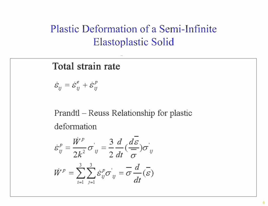


Plastic Deformation of a Semi-Infinite Elastoplastic Solid
Conversion of the time derivative to gradients:
d 'ε( ij; ij;W)=U ( ij; ij;W)dt ∂x
'σ∂'ε'σ
8
Plastic Deformation of a Semi-Infinite Elastoplastic Solid
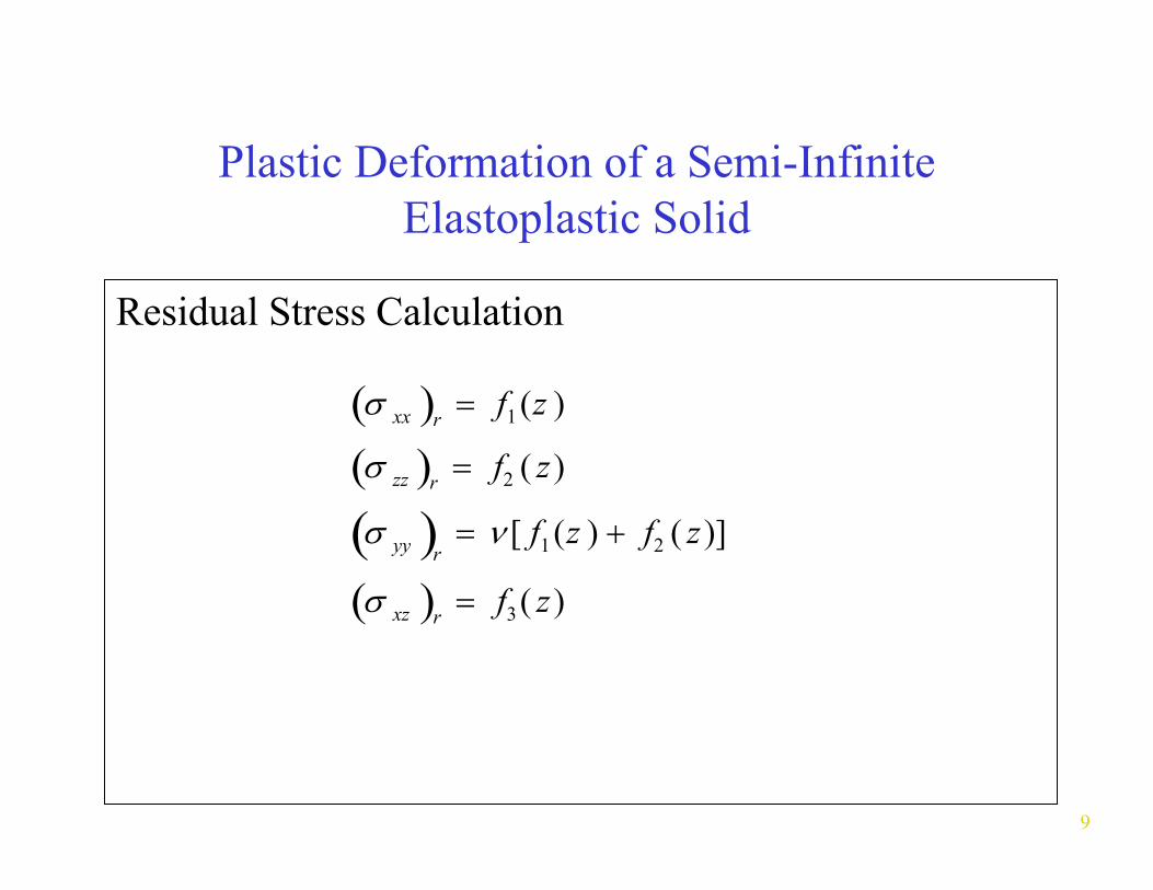
Residual Stress Calculation
σ( ) = f1 (z )xx r
σ( ) = f2 ( z )zz r
σ( ) = ν [ f1 (z ) + f2 ( z )]yy r
σ( ) = f3 ( z )xz r
9
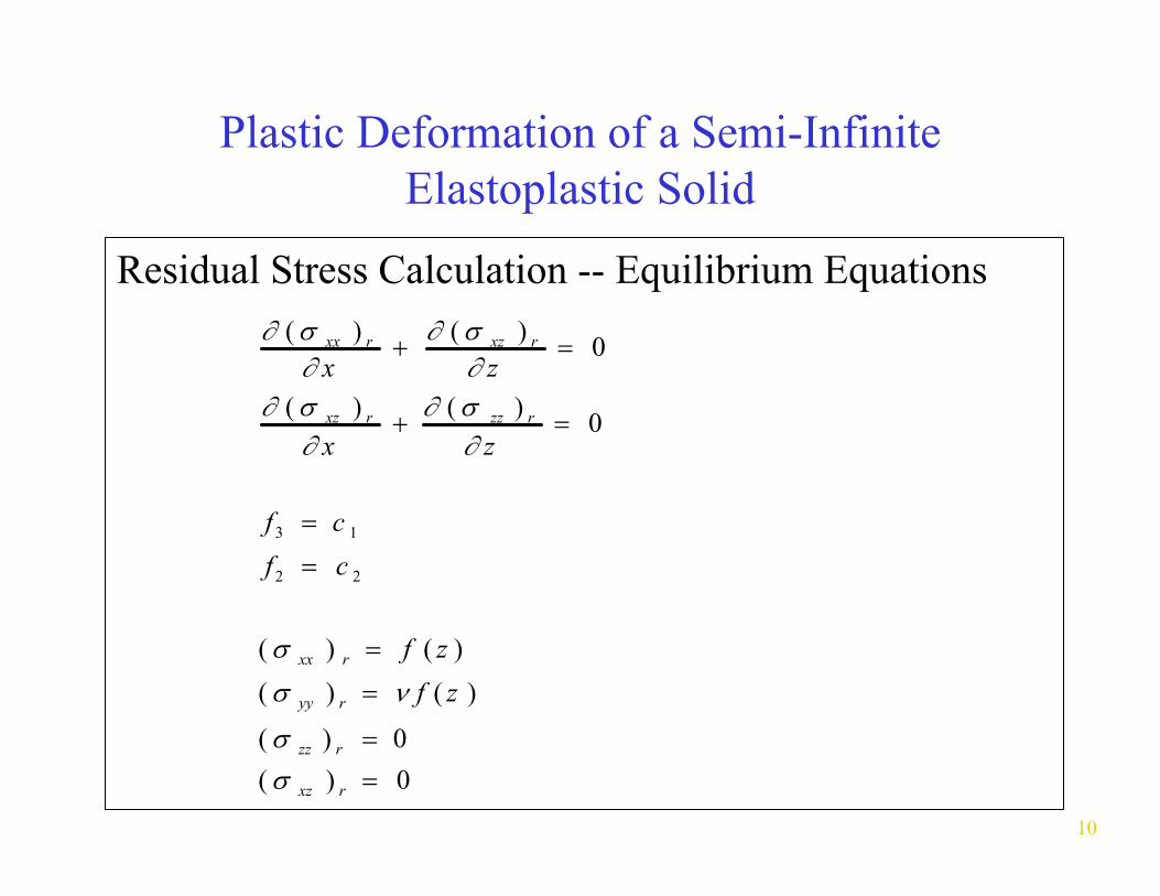
Plastic Deformation of a Semi-Infinite Elastoplastic Solid
Residual Stress Calculation -- Equilibrium Equations∂ ( σ ) ∂ ( σ xz ) r = 0xx r +
∂ x ∂ z
∂ ( σ ) ∂ ( σ zz ) r = 0xz r +∂ x ∂ z
f 3 = c 1
f 2 = c 2
( σ ) = f ( z )xx r
( σ yy ) = ν f ( z )r
( σ ) = 0zz r
( σ ) = 0xz r
10

Plastic Deformation of a Semi-Infinite Elastoplastic Solid
Residual Stress Calculation -- Equilibrium Equations
1− 2νε (σ zz )' rzz r( ) = −
2(1 −ν )G
( ) = −(σ xz )
' rγ xz r G
σ xx r σ xx
ν ( )' r( ) = ( )'
r −1− ν
σzz
σ σ( ) = σ yy' ν ( )' ryy r zz( )r −
1 −ν11

12
Crack Nucleation
• 1. Energy criterion 2. Strength criterion
• critical flaw size for crack nucleation, which is satisfied by most flaws in engineering materials.
Crack nucleation criteria
Because of the energy criterion, there is a

13
Crack Nucleation
• multi-phase metals. It takes only 100 to 1,000 cycles. Therefore, it is not the rate-controlling mechanism in these multi-phase metals.
Crack nucleation occurs rather readily in

14
Crack Nucleation
• the sub-surface is very difficult. Therefore,
be the primary wear mechanism. Wear by plowing of the surface by wear particles may be the primary wear-rate controlling mechanism.
In single phase metals, crack nucleation at
in these metals, delamination wear may not

Crack Nucleation
Imaginary sphere
A B
Deformed sphere of the Imaginary sphere
(a) (b)
Figure 4.36
15

Criteria for Crack Nucleation Energy Criterion and Strength Criterion
Stra
in, e
Energy criterion
Strength criterion
d*
Particle size, d Figure 4.37
16

Rigid Cylinder under a General State of Stress
x
z
τmax
σr r
φ
θ
Figure 4.38
17

Crack Nucleation
Strength criterion
( )σ kk max ≥ σ i
Energy criterion E s
before − E s after ≥ A ∆ γ
18

19
Crack Nucleation
d c
St rain
P articl e si ze
Ene rgy C rit er i o n
St re n g th Cr it e ri o n

20
Contour of σrr under a sliding contact (normalized with respect to k)
Graphs removed for copyright reasons. Tribophysics. EnglewoodSee Figures 4.39-4.41 in [Suh 1986]: Suh, N. P.
Cliffs NJ: Prentice-Hall, 1986. ISBN: 0139309837.

21
Depth of Void Nucleation Region as a function of µ and p0
Graph removed for copyright reasons. See Figure 4.42 in [Suh 1986].

22
Number of passes required for crack nucleation and the depth of crack nucleation at p0=4k
Graph removed for copyright reasons. See Figure 4.43 in [Suh 1986].

23
Number of passes required for crack nucleation and the depth of crack nucleation at p0=6k
Graph removed for copyright reasons. See Figure 4.44 in [Suh 1986].

24
Crack Propagation
• classified in terms of three modes.
direction.
In fracture mechanics, crack propagation is
1. The load is applied perpendicular to the crack. 2. The load is applied parallel to the crack direction. 3. The load is applied transversely to the crack

25
Crack Propagation
• is due to a combined loading of compression and shear on the crack -compressive stress on the crack and shear deformation at the crack tip.
However, crack propagation in sliding wear

26
Crack Propagation
• wear conditions is very slow, being about 30 microns per cycle of crack-tip sliding.
• multi-phase metals is controlled by the crack propagation rate.
The rate of crack propagation under sliding
Therefore, the delamination wear of many

27
Sliding Wear at Low Speeds
•
∆(CTSD) ~ 0.003 µm
Crack propagation rate controls the delamination wear rate.

F α
maximum
Tension
r
Compression
maximum
Crack
θ
Constant
shear stress
Constant
shear stress
28

29
Variation of plastically deformed zone around crack under a moving asperity
(a=10µm, d=0.5 a, µ=0.25, po=4k=980 MPa)
Plots removed for copyright reasons. See Figure 4.48 in [Suh 1986].

30
Shear strain vs. distance from the left crack tip when plastic elements are used.
Ph.D. Thesis, MIT, 1981.
Source: Sin, H-C. “Surface Fraction and Crack Propagation in Delamination Wear.”

31
Shear strain vs. distance from the right cracktip when plastic elements are used.
Ph.D. Thesis, MIT, 1981.
Source: Sin, H-C. “Surface Fraction and Crack Propagation in Delamination Wear.”

32
Shear strain as a function of distance from the left tip for different depths of crack location
Ph.D. Thesis, MIT, 1981.
Source: Sin, H-C. “Surface Fraction and Crack Propagation in Delamination Wear.”

Figure 4.52
33
Void and crack formation in annealed OFHC copper

Figure 4.53
34
Subsurface deformation and crack formation in Fe solid solution

Typical plot of the crack extension per cycle versus the logarithm of the change in the stress intensity factor
da/d
N (m
m/c
ycle
)
10-2 Final failure
10-4
10-6
1
m B
A
1
C
Kc
Threshold ∆K0
∆K)mda/dN = C(
log ∆K Figure 4.47
35

36
Void formation around inclusions and crack propagation from these voids near the surface
in annealed Fe-1.3% Mo
Photos removed for copyright reasons. See Figure 4.35 in [Suh 1986].

Subsurface crack under a moving asperity
L R-θc Ld
C
Figure 5.8 Subsurface crack under a moving asperity
37

38
Model of wearing specimen
Figure 5.9 Model of wearing specimen and slider
Slider
∆L
dD
lC
Specimen
λ

39
Worn surface of pure iron
dimpled appearance of wear crater
Photo removed for copyright reasons.
(a) sheet formation, (b) shear dimples beneath the wear sheet in (a), ©
See Figure 5.7 in [Suh 1986].

40
Fretting Wear
Graph removed for copyright reasons. See Figure 5.10 in [Suh 1986].

41
Ph.D. Thesis, MIT, 1981.
Source: Sin, H-C. “Surface Fraction and Crack Propagation in Delamination Wear.”

42
removed for copyright reasons. Sequence of graphs and photos
See Figures 5.12-5.23 in [Suh 1986].