CADD STANDARDS FOR HIGHWAY PLANS - … following CADD Standards for Highway Plans (version 3.12)...
24
Rev. 10/16/2014 1 CADD STANDARDS FOR HIGHWAY PLANS Introduction The following CADD Standards for Highway Plans (version 3.12) policy documents the required standards for all electronic files representing submittals of Contract Plans and Proposals to the Kentucky Department of Highways (KDOH). The primary goal of these standards is to insure the best possible use of these files in the review, publication, bidding, construction, and archive processes. The standards presented in this policy represent the minimum requirements that must be met for the development of Highway Plans. The Contract Plans are the Highway Plans that are awarded through the letting process. The Contract Plan Sets are the product of the Project Development process and are comprised of the Roadway, Structures, Traffic, and/or Utility Relocation Plans. It must be stressed that while the CADD Standards for Highway Plans are to be applied to the deliverable files for Contract Plans and Proposals, they should not be used to restrict the utility of plans submitted for inspections, public meetings, or interim reviews.
Transcript of CADD STANDARDS FOR HIGHWAY PLANS - … following CADD Standards for Highway Plans (version 3.12)...

Rev. 10/16/2014
1
CADD STANDARDS FOR HIGHWAY PLANS
Introduction
The following CADD Standards for Highway Plans (version 3.12) policy documents the required standards for all electronic files representing submittals of Contract Plans and Proposals to the Kentucky Department of Highways (KDOH). The primary goal of these standards is to insure the best possible use of these files in the review, publication, bidding, construction, and archive processes. The standards presented in this policy represent the minimum requirements that must be met for the development of Highway Plans.
The Contract Plans are the Highway Plans that are awarded through the letting process. The Contract Plan Sets are the product of the Project Development process and are comprised of the Roadway, Structures, Traffic, and/or Utility Relocation Plans.
It must be stressed that while the CADD Standards for Highway Plans are to be applied to the deliverable files for Contract Plans and Proposals, they should not be used to restrict the utility of plans submitted for inspections, public meetings, or interim reviews.

Rev. 10/16/2014
2
General Parameters
The following general parameters for the submittal of electronic files for Highway Plans have been established:
Electronic files representing the Contract Plans and Proposal will be delivered to the Project Manager for submittal to Central Office via ProjectWise®. ProjectWise will also be used for internal Cabinet deliveries to the Project Manager.
All deliverable files shall conform to a predetermined file naming and file structure methodology as detailed in this policy.
Files other than those that represent the Contract Plans and Proposal are required as part of the deliverables and shall be categorized as supplemental files. There shall be an overt distinction between the files that represent the contract plan and supplemental files. Supplemental files are given for informational purposes only.
All supplemental files representing engineering data shall be created and submitted in InRoads® format in the version most recently recognized by the Department.
All CADD files shall be created and submitted in MicroStation® (.DGN) format in the version most recently recognized by the Department.
For latest software version information refer to the CADD Standards web page @ http://www.transportation.ky.gov/caddstandards
Design files shall comply with the Department's graphic standards as detailed in this policy.
All CADD files shall use only the Department's standard MicroStation resource files.
All mapping features and all design features in plan view shall maintain their project datum coordinate location values. Detail sheets do not have to be shown in true coordinate location.
A one to one relationship (WYSIWYG) between the design file content and the plotted sheets shall be maintained.
Each sheet of the Plan Set that is drawn to a scale shall have a graphical scale located on that sheet.
® MicroStation, InRoads Civil Suites, and ProjectWise are registered trademarks of Bentley Systems.

Rev. 10/16/2014
3
Electronic Delivery
Electronic files representing the Contract Plans and Proposal will be delivered to the Project Manager for submittal to Central Office via ProjectWise. ProjectWise will also be used for internal Cabinet deliveries to the Project Manager. These electronic files will be shared and referenced by many different individuals and disciplines in order to reduce work duplication and improve the revision process. Therefore, this policy has been established for disciplines that share in the project development and outlines the minimum standards, conventions, and formats necessary to ensure a usable electronic file data set to the downstream customers.
Delivery Folder Structure
The delivery folder structure is a list of the required directories. These directories are required in the hierarchy as shown and none are to be deleted. Even when a directory is not used in a specific project, the directory shall remain.
The electronic plans shall consist of a project directory containing a “Contract Plans and Proposal” directory with four subordinate directories as shown below:
Project Directory Name
The project directory name will be the KYTC Project Identification Number (Item Number) and is standardized to achieve proper sorting. The Item Number should be in the following format:
AA-BBBB.CC Where “AA” represents the District Number and should consist of two digits. “BBBB” represents the Parent Number and should consist of four digits. “CC” represents the Parent Number breakout and should consist of two digits. Examples: 01-0115.00; 11-0273.01
Under the project directory, the “Contract Plans and Proposal” directory shall contain subdirectories for: Contract Plan Set, Miscellaneous, Proposal, and Supplemental.

Rev. 10/16/2014
4
Contract Plan Set
The "Contract Plan Set" shall contain MicroStation design files, each representing one sheet in the final plan set. Cross sections are the only exception to one sheet per design file. Each design file shall be self-contained, with no reference files. The “Contract Plan Set” shall also contain PDF files. There shall be one PDF file for each folder listed in the “Contract Plan Set” directory with each PDF file consisting of all the sheets representing the plan set for that discipline or folder.
The “Contract Plan Set” directory shall contain subdirectories for the following divisions: Roadway, Structures, Traffic, and Utilities. The “Contract Plan Set” directory will contain an index file to index all sheets (see Index File section for description). The index file shall be named “Index.txt”. Below is an example of this directory structure:
Roadway
The Roadway directory shall contain MicroStation design files, each representing a single sheet in the final plan set. Cross sections are the only exception to the single sheet per design file. The design file containing the cross sections will reside in the Roadway directory. While the Cross Sections may reside in one design file the index file for the Cross Sections shall list each Cross Section sheet and sheet description as contained in the plan set. Each design file shall be self-contained, with no reference files. The Roadway directory shall contain a PDF file consisting of all the sheets representing the roadway plan set. The Roadway directory will also contain index files to index all Roadway and Cross Section sheets (see Index File section for description). The Roadway index file shall be named “Index_R.txt” and the Cross Section index file shall be named “Index_XS.txt”. To obtain additional information concerning roadway plan development, please see the Division of Highway Design Guidance Manual. Below is an example of this directory structure:
Rev. 10/16/2014
5
Structures
The Structures directory shall contain subdirectories for each structure within the project. Each subdirectory will be named for the five-digit drawing number representing the structure. Below is an example of this directory structure where 12345 and 67890 represent the five digit drawing numbers:
Each Structure subdirectory shall contain MicroStation design files, each representing a single sheet in the final plan set. Each design file shall be self-contained, with no reference files. Each Structure subdirectory shall contain a PDF file consisting of all the sheets representing the Structure plan set. The Structure directory will also contain an index file to index all Structure sheets (see Index File section for description). The Structure index file shall be named “Index_S.txt”. To obtain additional information concerning structure plan development, please see the Structural Design Guidance Manual.
Traffic
The Traffic directory shall contain subdirectories for Lighting, Signals, and Signs. Below is an example of this directory structure:
As required for the project, each Traffic subdirectory shall contain MicroStation 2D design files corresponding to the appropriate discipline (Lighting, Signals, or Signs). These design files shall represent a single sheet in the final plan set. Each design file shall be self-contained, with no reference files. Each Traffic subdirectory shall contain a PDF file consisting of all the sheets representing the Traffic plan set. The Traffic directory will also contain an index file to index all Traffic sheets (see Index File section for description). The Traffic index file shall be named “Index_T.txt”. To obtain additional information concerning traffic plan development (i.e. traffic sheet order), please go to:
http://transportation.ky.gov/Traffic-Operations/Pages/default.aspx

Rev. 10/16/2014
6
Utilities
The Utilities directory shall contain Utility Relocation Sheets. The Utility Relocation Sheets shall represent utility work that will occur during construction of the roadway. Each Utilities subdirectory shall contain a PDF file consisting of all the sheets representing the utility relocation plan set. The Utilities directory will also contain an index file to index all Utilities sheets (see Index File section for description). The Utilities index file shall be named “Index_U.txt”. Below is an example of this directory structure:
Miscellaneous
The “Miscellaneous” directory will contain any documentation, correspondence, or special information relating to the project. Project documentation will include submittal forms, Design Executive Summaries (DES), environmental checklist, the final XML estimate file from Trns•port Estimator, an InRoads’ superelevation report on the final alignment(s), spreadsheet with the earthwork calculations (if available), project construction schedule (fixed completion date or maximum work days), permit/water quality certification (if required), final production-hour worksheet (for consultant projects), and any other documentation the Project Manager deems pertinent.
Proposal
The “Proposal” directory will contain any documentation, correspondence, or special information relating to the project’s proposal. Proposal documentation will include Best Management Practices (BMP) document, Topographic Map for eNOI Submittal (.pdf format), eNOI Transaction ID Number (.pdf format), the CAP report (even when there are no entries in the CAP), utility impact notes, special provisions for protection of railroad interest, project specific special notes or specifications, etc. This directory is also reserved for the eventual inclusion of the electronic proposal document currently distributed by the Division of Contract Procurement.
Supplemental
The “Supplemental” directory will contain files other than those that represent the Contract Plans and Proposal. There shall be an overt distinction between the files that represent the contract plans and supplemental files. Supplemental files are given for informational purposes only.
Rev. 10/16/2014
7
The InRoads Digital Terrain Model (.dtm) and InRoads alignment file (.alg) will need to be translated to LandXML data files. LandXML is a non-proprietary data standard format for civil engineering and survey data used in the Land Development and Transportation Industries. A Translator in InRoads v8.5 and higher will export surface and alignment data to LandXML files. (Go to LandXML.org for more information on the LandXML Schema.) NOTE: The designer must include InRoads’ features & exclude triangles when creating the Proposed Roadway Model in the LandXML Schema.
All supplemental files representing engineering data shall be created and submitted in InRoads® format in the version most recently recognized by the Department.
All CADD files shall be created and submitted in MicroStation (.DGN) format in the version most recently recognized by the Department.
For latest InRoads and MicroStation version information refer to the CADD Standards webpage @ http://transportation.ky.gov/CADD-Standards/Pages/default.aspx
The table on the next page documents the supplemental electronic project files that will be delivered with the Final Contract Plans.

Rev. 10/16/2014
8
Supplemental Files
Supplemental Information
File Format(s)
File Name(s)
Notes
Mapping files (3D)
MicroStation .DGN
exmanu.dgn Include complete original mapping (existing manuscript) delivered from the aerial survey data or ground collected data.
Existing Ground Digital Terrain
Data
InRoads .DTM and .XML in the LandXML
Schema
exground.dtm
and exground.xml
The existing digital terrain data of the project area.
Coordinate Control Data
ASCII coordata.csv Include all primary and supplemental coordinate control information (including right of way monumentation) in the following form: Point Number, Northing, Easting, Elevation, Description NOTE: Elevation is not needed on right of way monumentation points.
Alignment Geometry
InRoads .ALG and .XML
in the LandXML Schema
geometry.alg
and
geometry.xml
These files will contain all centerline horizontal and vertical alignments for the project. Name the alignments the appropriate route number or name.
InRoads' Superelevation
Report
Report in .XML in the LandXML
Schema
super.xml Data file will contain information about the superelevation.
Earthwork Calculations Spreadsheet ( If available)
Report in Excel or other
recognizable Spreadsheet
earthwrk.xls Some Designers use spreadsheets to calculate earthwork information. Please include this file, if available.
Proposed Roadway
Model (including InRoads’ Features) & Design
Information
InRoads .DTM, .ITL, & .IRD files
and the Proposed
Roadway Model in the
LandXML Schema
roadmod.dtm, typicals.itl,
roaddesign.ird
and
roadmod.xml (Include InRoads’
Features & exclude triangles in roadmod.xml.)
The proposed digital roadway model and design data is for informational purposes only. This proposed roadway model will likely be inaccurate and/or incomplete. This data is “User: Beware.” The designer must include InRoads’ features & exclude triangles when creating the Proposed Roadway Model in the LandXML Schema.
Proposed Manuscript
(3D information showing the
roadway design
MicroStation .DGN
propmanu3d.dgn Include existing contours, existing planimetrics, proposed features, and control points. Data should be at proposed coordinates & elevations. This data is “User: Beware.” NOTE: If roadway was designed by “sheet” method instead of manuscript, reference all sheets into one DGN file and save as “propmanu3d.dgn”
NOTE: LandXML is a non-proprietary data standard format for civil engineering and survey data used in the Land Development and Transportation Industries. A Translator in InRoads will export surface and alignment data to LandXML files. Go to LandXML.org for more information on the LandXML Schema.

Rev. 10/16/2014
9
Standard MicroStation .DGN File Names
The following file naming conventions shall be used for all design files. In the event a particular file type is needed for the project and it is not addressed by this document, use the file naming convention as a template for selecting an appropriate name.
Roadway, Traffic, and Utilities Design Files
These design files should abide by the following naming convention:
A1112BCC.dgn
Where A = the sheet type, 111 = the sheet number, 2B = the sequence code, and CC = the sheet code.
Sheet Types R – Roadway T – Traffic U – Utilities X – Roadway Cross Sections
Sheet Codes – Roadway
LS - Layout Sheet TS - Typical Sections SU - Summaries GN - General Notes Sheets PL - Plan Sheets PF - Profiles UR - Utility Reference Sheets RW - Right of Way Summaries and Strip Maps DS - Detail Sheets MT - Maintenance of Traffic Sheets EC - Erosion Control Sheets CC - Coordinate Control Sheets GT - Geotechnical and Soil Profiles Sheets MP – Mitigation Plan Sheets PD - Pipe Drainage Sheets XS - Cross Sections
Sequence Codes The Sequence Codes utilize alpha characters to designate the next sheet in the series, i.e. Sheet #2A has a Sequence Code “0A”.
Sheet Codes - Traffic
LS – Cover Sheet SU – Quantity Sheet GN – General Details CA – Cabinet Details CL – Conventional Lighting Details HM – Highmast Details LP – Loop Details PO – Pole Details MA – Mast Arm Details JB – Junction Box Details SE – Services Details BW – Barrier Wall Details NA – Navigational Lights Details RA – Radio Details SF – School Flashers Details SP – Special Details LT – Lighting Plan Sheets SG – Signal Plan Sheets SN – Signing Plan Sheets
Rev. 10/16/2014
10
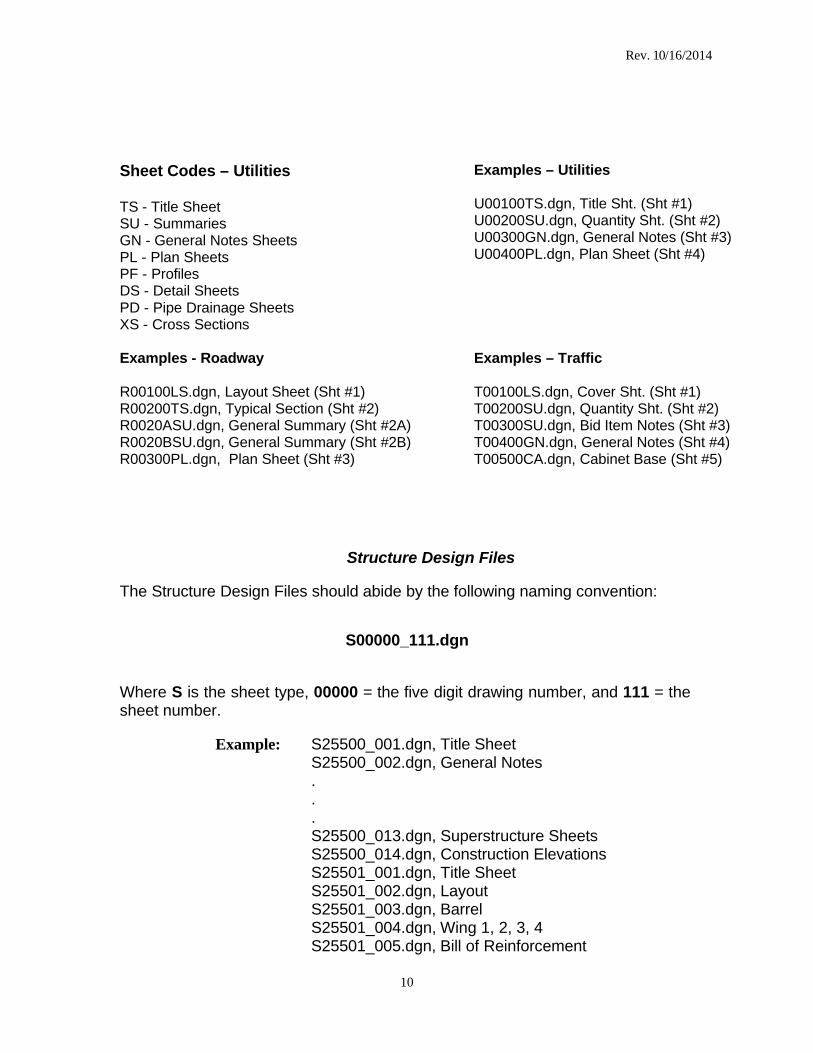
Sheet Codes – Utilities
TS - Title Sheet SU - Summaries GN - General Notes Sheets PL - Plan Sheets PF - Profiles DS - Detail Sheets PD - Pipe Drainage Sheets XS - Cross Sections
Examples – Utilities
U00100TS.dgn, Title Sht. (Sht #1) U00200SU.dgn, Quantity Sht. (Sht #2) U00300GN.dgn, General Notes (Sht #3) U00400PL.dgn, Plan Sheet (Sht #4)
Examples - Roadway
R00100LS.dgn, Layout Sheet (Sht #1) R00200TS.dgn, Typical Section (Sht #2) R0020ASU.dgn, General Summary (Sht #2A) R0020BSU.dgn, General Summary (Sht #2B) R00300PL.dgn, Plan Sheet (Sht #3)
Examples – Traffic
T00100LS.dgn, Cover Sht. (Sht #1) T00200SU.dgn, Quantity Sht. (Sht #2) T00300SU.dgn, Bid Item Notes (Sht #3) T00400GN.dgn, General Notes (Sht #4) T00500CA.dgn, Cabinet Base (Sht #5)
Structure Design Files
The Structure Design Files should abide by the following naming convention:
S00000_111.dgn
Where S is the sheet type, 00000 = the five digit drawing number, and 111 = the sheet number.
Example: S25500_001.dgn, Title Sheet
S25500_002.dgn, General Notes . . . S25500_013.dgn, Superstructure Sheets S25500_014.dgn, Construction Elevations S25501_001.dgn, Title Sheet S25501_002.dgn, Layout S25501_003.dgn, Barrel S25501_004.dgn, Wing 1, 2, 3, 4 S25501_005.dgn, Bill of Reinforcement
Rev. 10/16/2014
11
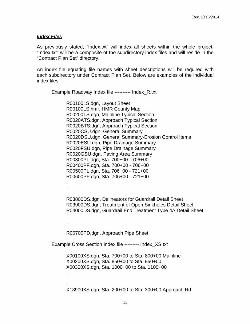
Index Files
As previously stated, “Index.txt” will index all sheets within the whole project. “Index.txt” will be a composite of the subdirectory index files and will reside in the “Contract Plan Set” directory.
An index file equating file names with sheet descriptions will be required with each subdirectory under Contract Plan Set. Below are examples of the individual index files:
Example Roadway Index file ---------- Index_R.txt
R00100LS.dgn, Layout Sheet R00100LS.hmr, HMR County Map R00200TS.dgn, Mainline Typical Section R0020ATS.dgn, Approach Typical Section R0020BTS.dgn, Approach Typical Section R0020CSU.dgn, General Summary R0020DSU.dgn, General Summary-Erosion Control Items R0020ESU.dgn, Pipe Drainage Summary R0020FSU.dgn, Pipe Drainage Summary R0020GSU.dgn, Paving Area Summary R00300PL.dgn, Sta. 700+00 - 706+00 R00400PF.dgn, Sta. 700+00 - 706+00 R00500PL.dgn, Sta. 706+00 - 721+00 R00600PF.dgn, Sta. 706+00 - 721+00 . . . R03800DS.dgn, Delineators for Guardrail Detail Sheet R03900DS.dgn, Treatment of Open Sinkholes Detail Sheet R04000DS.dgn, Guardrail End Treatment Type 4A Detail Sheet . . . R06700PD.dgn, Approach Pipe Sheet
Example Cross Section Index file --------- Index_XS.txt
X00100XS.dgn, Sta. 700+00 to Sta. 800+00 Mainline X00200XS.dgn, Sta. 850+00 to Sta. 950+00 X00300XS.dgn, Sta. 1000+00 to Sta. 1100+00 . . . X18900XS.dgn, Sta. 200+00 to Sta. 300+00 Approach Rd
Rev. 10/16/2014
12
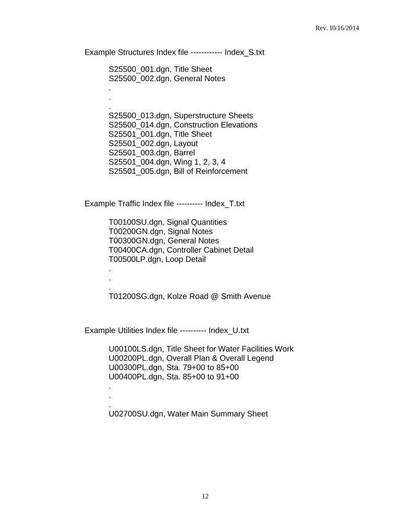
Example Structures Index file ------------ Index_S.txt
S25500_001.dgn, Title Sheet S25500_002.dgn, General Notes . . . S25500_013.dgn, Superstructure Sheets S25500_014.dgn, Construction Elevations S25501_001.dgn, Title Sheet S25501_002.dgn, Layout S25501_003.dgn, Barrel S25501_004.dgn, Wing 1, 2, 3, 4 S25501_005.dgn, Bill of Reinforcement
Example Traffic Index file ---------- Index_T.txt
T00100SU.dgn, Signal Quantities T00200GN.dgn, Signal Notes T00300GN.dgn, General Notes T00400CA.dgn, Controller Cabinet Detail T00500LP.dgn, Loop Detail . . . T01200SG.dgn, Kolze Road @ Smith Avenue
Example Utilities Index file ---------- Index_U.txt
U00100LS.dgn, Title Sheet for Water Facilities Work U00200PL.dgn, Overall Plan & Overall Legend U00300PL.dgn, Sta. 79+00 to 85+00 U00400PL.dgn, Sta. 85+00 to 91+00 . . . U02700SU.dgn, Water Main Summary Sheet
Rev. 10/16/2014
13
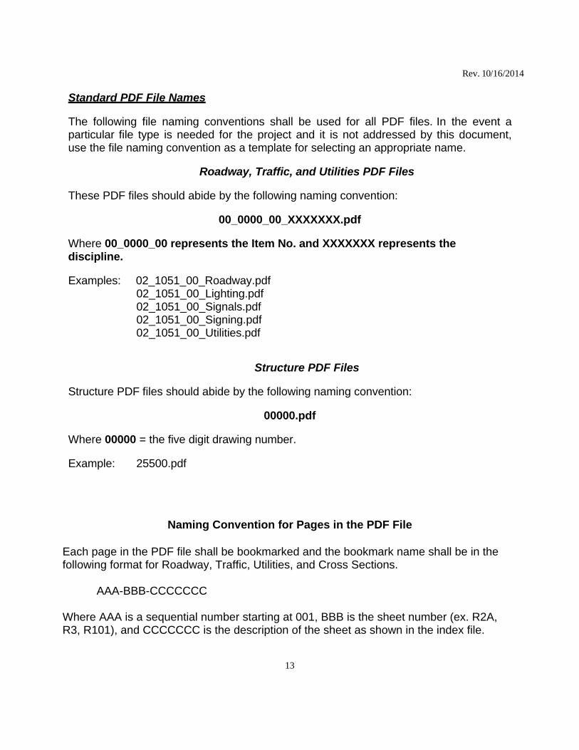
Standard PDF File Names
The following file naming conventions shall be used for all PDF files. In the event a particular file type is needed for the project and it is not addressed by this document, use the file naming convention as a template for selecting an appropriate name.
Roadway, Traffic, and Utilities PDF Files
These PDF files should abide by the following naming convention:
00_0000_00_XXXXXXX.pdf
Where 00_0000_00 represents the Item No. and XXXXXXX represents the discipline.
Examples: 02_1051_00_Roadway.pdf
02_1051_00_Lighting.pdf 02_1051_00_Signals.pdf 02_1051_00_Signing.pdf 02_1051_00_Utilities.pdf
Structure PDF Files Structure PDF files should abide by the following naming convention:
00000.pdf
Where 00000 = the five digit drawing number.
Example: 25500.pdf
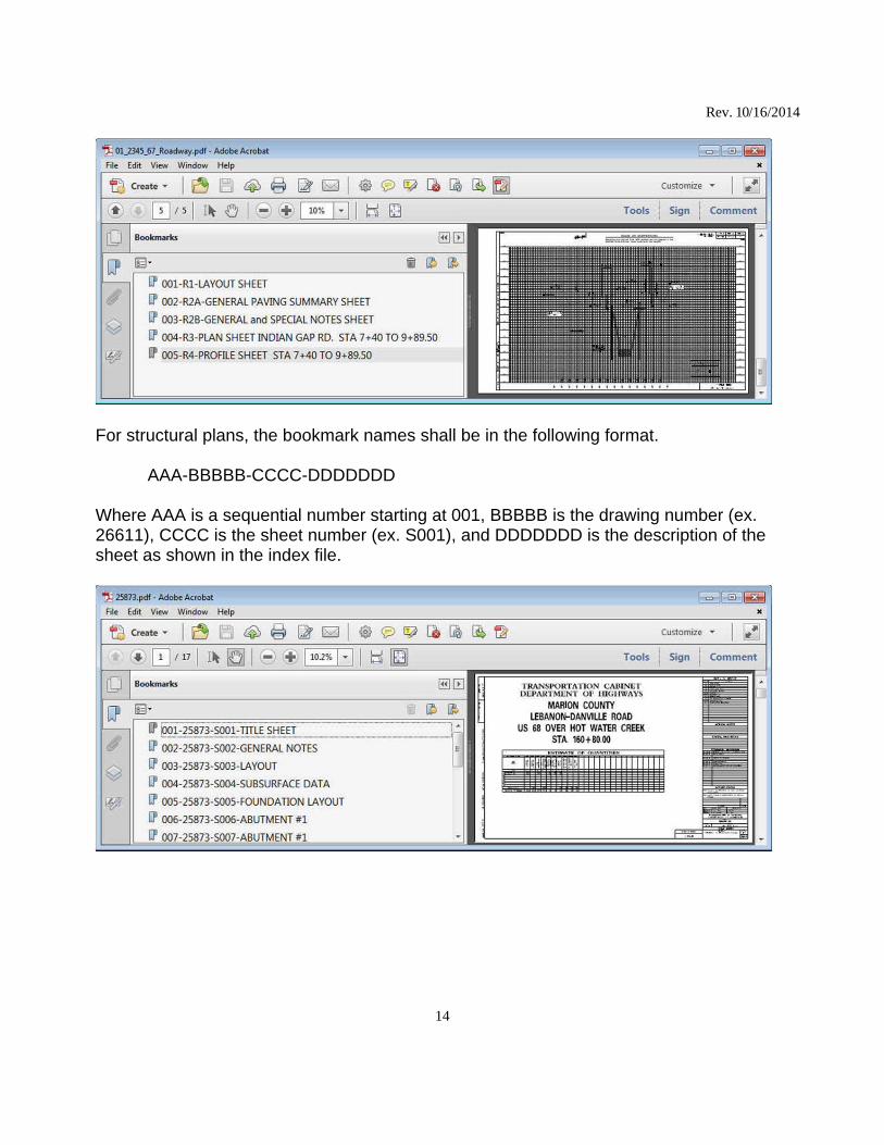
Naming Convention for Pages in the PDF File Each page in the PDF file shall be bookmarked and the bookmark name shall be in the following format for Roadway, Traffic, Utilities, and Cross Sections. AAA-BBB-CCCCCCC Where AAA is a sequential number starting at 001, BBB is the sheet number (ex. R2A, R3, R101), and CCCCCCC is the description of the sheet as shown in the index file.
Rev. 10/16/2014
14
For structural plans, the bookmark names shall be in the following format. AAA-BBBBB-CCCC-DDDDDDD Where AAA is a sequential number starting at 001, BBBBB is the drawing number (ex. 26611), CCCC is the sheet number (ex. S001), and DDDDDDD is the description of the sheet as shown in the index file.

Rev. 10/16/2014
15
Graphics Standards
All CADD files shall be in MicroStation design format and shall comply with the KDOH graphics standards. Raster components within CADD files are acceptable on a limited basis (i.e. map portion of the Layout sheet, photo backdrop portion of R/W strip map). File name extensions shall be .DGN for all CADD files.
CADD file Working Units shall be set as follows to accommodate the complete state plane coordinate system while providing adequate precision.
Working Units for Roadway, Traffic, and Utilities plans shall be Master Unit = Survey Feet (Label = '), Sub Unit = Custom SU (Label = tn) Resolution = 1000 per Foot
Working Units for Structure plans shall be Master Unit = Feet (Label = ’), Sub Unit = Inches (Label =”) Resolution = 12000 per Foot
As per the Department’s Surveying Standards, the Kentucky Single Zone, as it relates to State Plane Coordinates, is being used on projects in lieu of Kentucky North or South Zone. The Kentucky Single Zone provides a consistent coordinate system on a statewide basis that minimizes ground to grid distortions and convergence angles.
All mapping submitted to the Department shall comply with the CADD Standards. The delivered manuscript file shall be a 3D MicroStation DGN file, current version as recognized by the Department. The accompanying ALG and DTM files shall be in the current version of InRoads. The DTM shall consist of logical planametric features that adhere to InRoads Feature Styles contained in the Department’s InRoads XIN (Preference) file. Furthermore, the features shall adhere to the survey codes accepted by the Department and listed on the website below:
http://transportation.ky.gov/design/survey/data collector codes_alphaorder.pdf
All mapping and design features that have coordinate location values associated with them shall maintain those coordinate values within the CADD files. Do not rotate or translate design file elements. View rotation should be used to obtain the appropriate orientation of the sheet. Detail sheets do not have to be shown in true coordinate location.
All sheets in the contract plans shall have a corresponding MicroStation .DGN file (i.e. one sheet per file), with the exception of cross sections files, which may contain multiple cross section sheets in a single file.
Rev. 10/16/2014
16
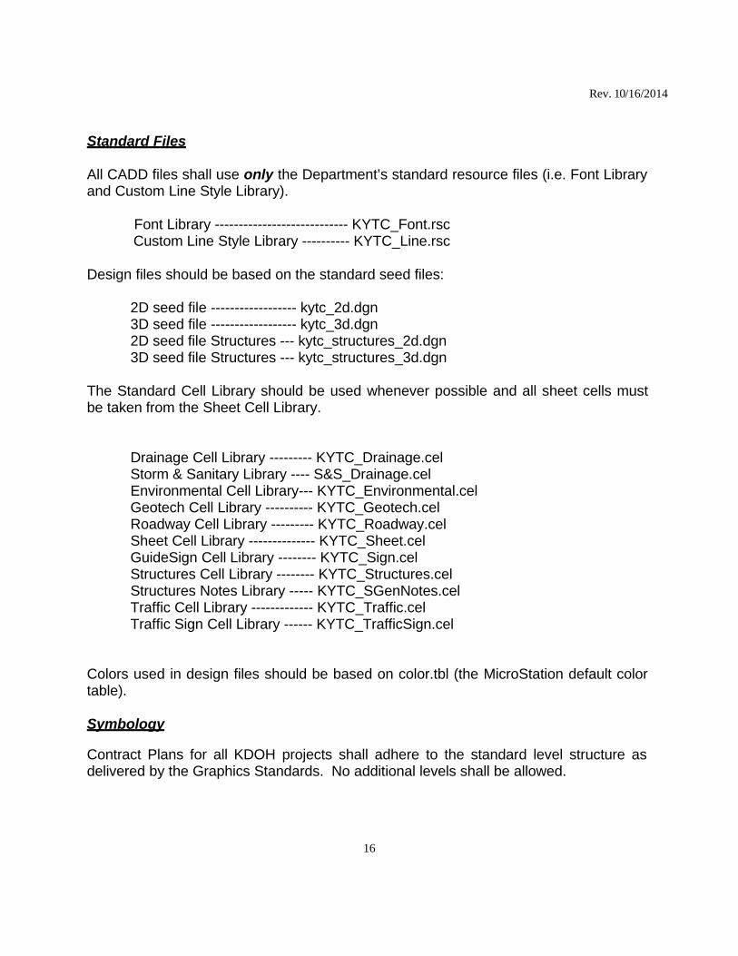
Standard Files
All CADD files shall use only the Department’s standard resource files (i.e. Font Library and Custom Line Style Library).
Font Library ---------------------------- KYTC_Font.rsc Custom Line Style Library ---------- KYTC_Line.rsc
Design files should be based on the standard seed files:
2D seed file ------------------ kytc_2d.dgn 3D seed file ------------------ kytc_3d.dgn 2D seed file Structures --- kytc_structures_2d.dgn 3D seed file Structures --- kytc_structures_3d.dgn
The Standard Cell Library should be used whenever possible and all sheet cells must be taken from the Sheet Cell Library.
Drainage Cell Library --------- KYTC_Drainage.cel Storm & Sanitary Library ---- S&S_Drainage.cel Environmental Cell Library--- KYTC_Environmental.cel Geotech Cell Library ---------- KYTC_Geotech.cel Roadway Cell Library --------- KYTC_Roadway.cel Sheet Cell Library -------------- KYTC_Sheet.cel GuideSign Cell Library -------- KYTC_Sign.cel Structures Cell Library -------- KYTC_Structures.cel Structures Notes Library ----- KYTC_SGenNotes.cel Traffic Cell Library ------------- KYTC_Traffic.cel Traffic Sign Cell Library ------ KYTC_TrafficSign.cel
Colors used in design files should be based on color.tbl (the MicroStation default color table).
Symbology
Contract Plans for all KDOH projects shall adhere to the standard level structure as delivered by the Graphics Standards. No additional levels shall be allowed.
Rev. 10/16/2014
17
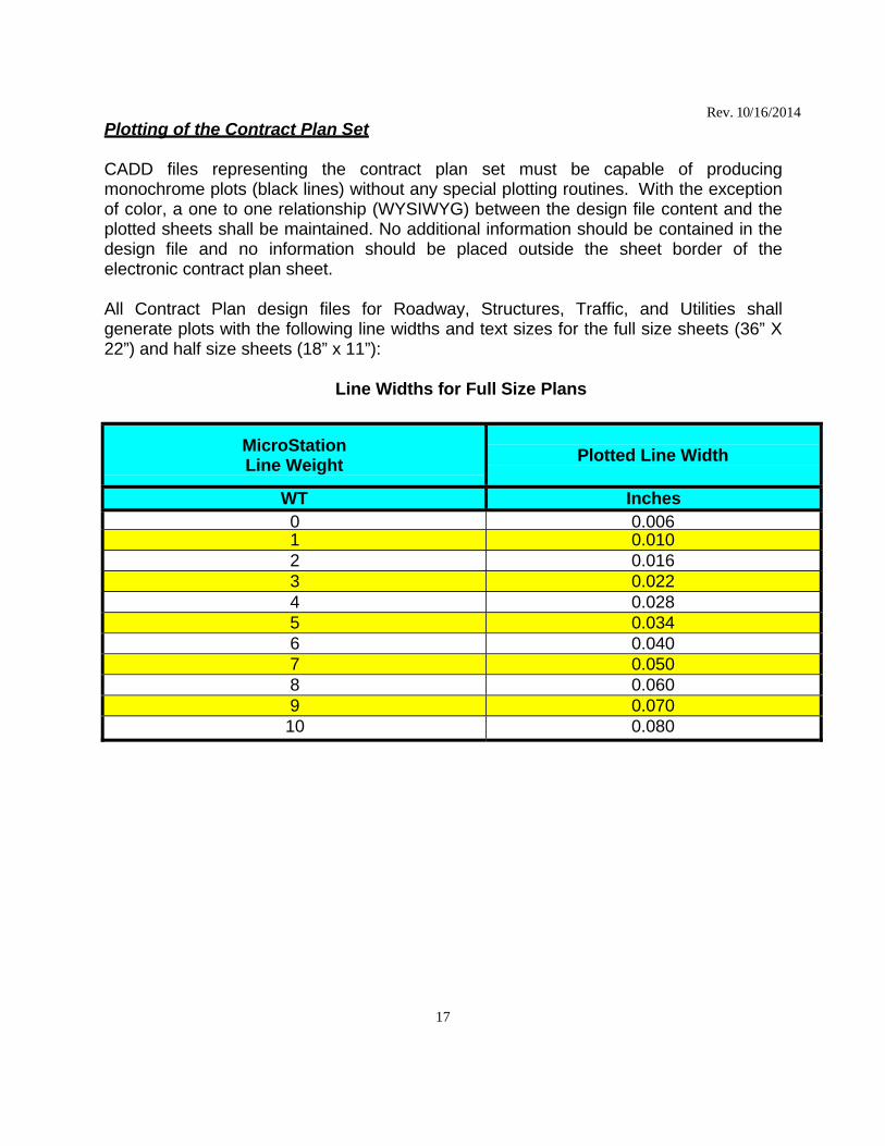
Plotting of the Contract Plan Set
CADD files representing the contract plan set must be capable of producing monochrome plots (black lines) without any special plotting routines. With the exception of color, a one to one relationship (WYSIWYG) between the design file content and the plotted sheets shall be maintained. No additional information should be contained in the design file and no information should be placed outside the sheet border of the electronic contract plan sheet.
All Contract Plan design files for Roadway, Structures, Traffic, and Utilities shall generate plots with the following line widths and text sizes for the full size sheets (36” X 22”) and half size sheets (18” x 11”):
Line Widths for Full Size Plans
MicroStation Line Weight
Plotted Line Width
WT Inches 0 0.006 1 0.010 2 0.016 3 0.022 4 0.028 5 0.034 6 0.040 7 0.050 8 0.060 9 0.070 10 0.080
18
Rev. 10/16/2014
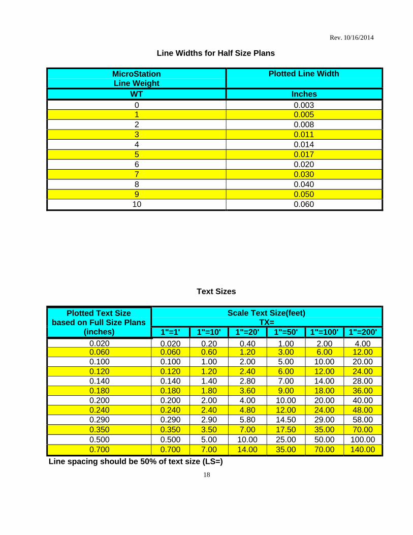
Line Widths for Half Size Plans
MicroStation Line Weight
Plotted Line Width
WT Inches 0 0.003 1 0.005 2 0.008 3 0.011 4 0.014 5 0.017 6 0.020 7 0.030 8 0.040 9 0.050 10 0.060
Text Sizes
Plotted Text Size based on Full Size Plans
(inches)
Scale Text Size(feet) TX=
1"=1' 1"=10' 1"=20' 1"=50' 1"=100' 1"=200'
0.020 0.020 0.20 0.40 1.00 2.00 4.000.060 0.060 0.60 1.20 3.00 6.00 12.00 0.100 0.100 1.00 2.00 5.00 10.00 20.00 0.120 0.120 1.20 2.40 6.00 12.00 24.00 0.140 0.140 1.40 2.80 7.00 14.00 28.00 0.180 0.180 1.80 3.60 9.00 18.00 36.00 0.200 0.200 2.00 4.00 10.00 20.00 40.00 0.240 0.240 2.40 4.80 12.00 24.00 48.00 0.290 0.290 2.90 5.80 14.50 29.00 58.00 0.350 0.350 3.50 7.00 17.50 35.00 70.00 0.500 0.500 5.00 10.00 25.00 50.00 100.00 0.700 0.700 7.00 14.00 35.00 70.00 140.00
Line spacing should be 50% of text size (LS=)
19
Rev. 10/16/2014
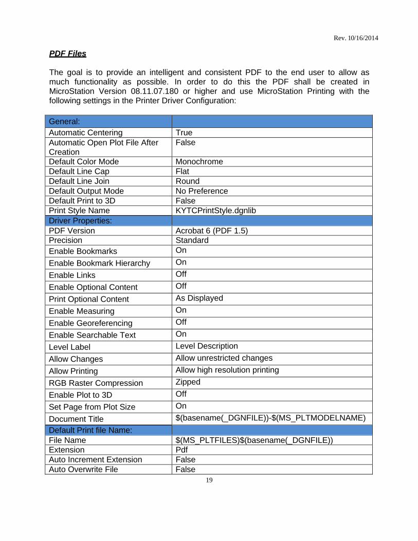
PDF Files
The goal is to provide an intelligent and consistent PDF to the end user to allow as much functionality as possible. In order to do this the PDF shall be created in MicroStation Version 08.11.07.180 or higher and use MicroStation Printing with the following settings in the Printer Driver Configuration:
General:
Automatic Centering True Automatic Open Plot File After Creation
False
Default Color Mode Monochrome Default Line Cap Flat Default Line Join Round Default Output Mode No Preference Default Print to 3D False Print Style Name KYTCPrintStyle.dgnlib Driver Properties:
PDF Version Acrobat 6 (PDF 1.5)Precision Standard Enable Bookmarks On
Enable Bookmark Hierarchy On
Enable Links Off
Enable Optional Content Off
Print Optional Content As Displayed
Enable Measuring On
Enable Georeferencing Off
Enable Searchable Text On
Level Label Level Description
Allow Changes Allow unrestricted changes
Allow Printing Allow high resolution printing
RGB Raster Compression Zipped
Enable Plot to 3D Off
Set Page from Plot Size On
Document Title $(basename(_DGNFILE))-$(MS_PLTMODELNAME)
Default Print file Name:
File Name $(MS_PLTFILES)$(basename(_DGNFILE)) Extension Pdf Auto Increment Extension False Auto Overwrite File False
20
Rev. 10/16/2014
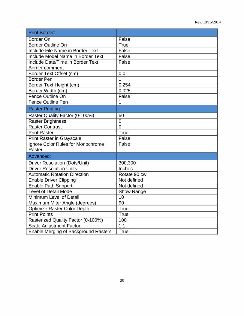
Print Border:
Border On False Border Outline On True Include File Name in Border Text False Include Model Name in Border Text False Include Date/Time in Border Text False Border comment
Border Text Offset (cm) 0,0 Border Pen 1 Border Text Height (cm) 0.254 Border Width (cm) 0.025 Fence Outline On False Fence Outline Pen 1 Raster Printing:
Raster Quality Factor (0-100%) 50 Raster Brightness 0 Raster Contrast 0 Print Raster True Print Raster in Grayscale False Ignore Color Rules for Monochrome Raster
False
Advanced:
Driver Resolution (Dots/Unit) 300,300 Driver Resolution Units Inches Automatic Rotation Direction Rotate 90 cw Enable Driver Clipping Not defined Enable Path Support Not defined Level of Detail Mode Show Range Minimum Level of Detail 10 Maximum Miter Angle (degrees) 90 Optimize Raster Color Depth True Print Points True Rasterized Quality Factor (0-100%) 100 Scale Adjustment Factor 1,1 Enable Merging of Background Rasters True
21
Rev. 10/16/2014
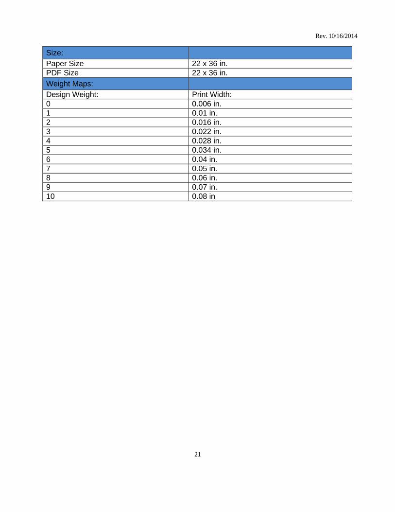
Size:
Paper Size 22 x 36 in. PDF Size 22 x 36 in.
Weight Maps:
Design Weight: Print Width: 0 0.006 in. 1 0.01 in. 2 0.016 in. 3 0.022 in. 4 0.028 in. 5 0.034 in. 6 0.04 in. 7 0.05 in. 8 0.06 in. 9 0.07 in. 10 0.08 in
22
Rev. 10/16/2014
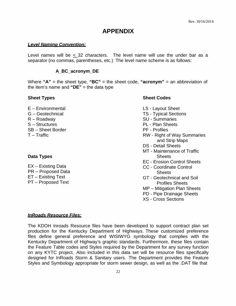
APPENDIX Level Naming Convention:
Level names will be < 32 characters. The level name will use the under bar as a separator (no commas, parentheses, etc.) The level name scheme is as follows:
A_BC_acronym_DE
Where “A” = the sheet type, “BC” = the sheet code, “acronym” = an abbreviation of the item’s name and “DE” = the data type
Sheet Types E – Environmental G – Geotechnical R – Roadway S – Structures SB – Sheet Border T – Traffic
Data Types
EX – Existing Data PR – Proposed Data ET – Existing Text PT – Proposed Text
Sheet Codes LS - Layout Sheet TS - Typical Sections SU - Summaries PL - Plan Sheets PF - Profiles RW - Right of Way Summaries
and Strip Maps DS - Detail Sheets MT - Maintenance of Traffic
Sheets EC - Erosion Control Sheets CC - Coordinate Control
Sheets GT - Geotechnical and Soil
Profiles Sheets MP – Mitigation Plan Sheets PD - Pipe Drainage Sheets XS - Cross Sections
InRoads Resource Files:
The KDOH Inroads Resource files have been developed to support contract plan set production for the Kentucky Department of Highways. These customized preference files define general preference and WISIWYG symbology that complies with the Kentucky Department of Highway’s graphic standards. Furthermore, these files contain the Feature Table codes and Styles required by the Department for any survey function on any KYTC project. Also included in this data set will be resource files specifically designed for InRoads Storm & Sanitary users. The Department provides the Feature Styles and Symbology appropriate for storm sewer design, as well as the .DAT file that

23
Rev. 10/16/2014
is required by S&S to properly size drainage structures in accordance with KYTC Standard Drawings. Also included is a Drafting Notes file for the convenience of the user. These preference files should be used in conjunction with the other KDOH CADD Standard Resource files; both files utilize custom line styles, cells, and fonts from the KDOH CADD Standard resource files.
CIVIL_V8i.xin S&S_V8i.xin KYTC_i_structures_S&S.dat InRoads Notes.dft KYTC Components.itl
ProjectWise InterPlot Organizer Design Scripts:
The KDOH Design Scripts have been developed to support contract plan set production for the Kentucky Department of Highways. These customized design scripts define the line weight symbology that complies with the Kentucky Department of Highway’s graphic standards for full size plan sets and half size plan sets.
KYTC_Full.pen KYTC_Half.pen
MicroStation Pen Tables:
MicroStation Pen Tables (MS Pen Tables) have been developed to define the line weight symbology that complies with the Kentucky Department of Highway’s graphic standards. The following pen tables were developed to support contract plan set production for the users of MicroStation print/plot:
KYTC_Full.tbl KYTC_Half.tbl
Cell Libraries:
There are ten cell libraries available to the designer. Level Symbology
Level symbologies shall be turned off for the delivery of the Contract Plan Set.
24
Rev. 10/16/2014
Data Fields
Data fields have been incorporated into the sheet cells to aid in the placing of annotation. When data field view is turned on (Settings View Attributescheck the Data Fields box), data fields will appear as a blue dashed line. You do not have to have the Data Field view turned on in order to add text to a data field. To add text to a data field, choose the Fill in Single Enter_Data Field button from the text toolbar. Data Point on the data field you wish to edit. Enter text in the Text Editor Dialog box and data point to accept. To delete text from a data field without deleting the data field, click on the Fill in Single Enter_Data Field button. Click on the data field with the text you wish to delete. Delete the text from the Text Editor Dialog box and hit the space bar then data point to accept. The text will be deleted but the data field will remain. For more information on Data Fields please refer to the MicroStation Help.
If a user wishes to enter text without the aid of Data Fields simply uncheck the Data Fields box under SettingsView Attributes.
Graphical vs. Symbolic Representation
Some features give the designer the option of displaying the feature on the plans using either a graphical or a symbolic representation. For example, an 18” water main may be graphically displayed by drawing parallel lines 18” apart representing the edges of the 18” pipe and labeling as an 18” water line. Instead of displaying the 18” water main graphically the designer may choose to display the 18” water main symbolically by using the water main line style to draw a line representing the center of the 18” water main and labeling the line as an 18” water main.