CADD Design Standards
372
Transcript of CADD Design Standards


CADD Design Standards
August 2020
CADD - Page 3 Preface
PREFACE
THE DESIGN MANUAL
As part of the ongoing design and construction programs at Ronald Reagan Washington National Airport and Washington
Dulles International Airport, the Metropolitan Washington Airports Authority (the Authority), Office of Engineering, has
developed and adopted a series of documents that describe the codes, standards, details, products, and practices to be
followed by Architect/Engineers (A/Es). These documents apply to all design of construction at all facilities on property
owned by the Authority. Facilities constructed or modified on the site occupied by the National Air and Space Museum
located at Washington Dulles International Airport are exempt from the requirements of the Authority Design Manual.
The Design Manual has been developed to assist Architects/Engineers (A/Es) in understanding the practices and policies
that must be incorporated into each project. The Design Manual contains a number of specific requirements that must be
followed on all projects, as described above. These can be either Authority contracted projects, Authority direct-constructed
projects, and tenant contracted projects.
APPLICABILITY OF THE DESIGN MANUAL
The requirements for design and construction incorporated into the Design Manual and Supporting Volumes are regulations
approved by the Metropolitan Washington Airports Authority Board of Directors and shall be considered contract
requirements for all A/Es who are performing services under contract to the Authority. Although A/Es who are under contract
to tenants of the Authority may not be working under contract provisions that make compliance with these requirements
mandatory, the Authority reserves the right, as Owner of all airport facilities, and land on which tenant buildings are
constructed, to reject any design or work that does not comply with the requirements of the Design Manual and its
supporting volumes. It is, therefore, required that all A/Es performing work that will be constructed on airport property shall
perform services consistent with the Authority policies, standards, procedures, and construction requirements contained in
the Design Manual and its supporting volumes. The Design Manual shall be considered equivalent to the building codes.
The Design Manual in effect at the 30% Submittal will remain the Design Manual of record up to the 100% Final Submittal.
ORGANIZATION OF THE DESIGN MANUAL
The Design Manual is made up of seven volumes.
Basic policies, procedures and standards for both Airports:
Design Manual
Requirements for Ronald Reagan Washington National Airport:
DCA Vol. 1 - Airport Standards and Signing Guidelines
DCA Vol. 2 - Tenant Design Standards
Requirements for Washington Dulles International Airport:
IAD Vol. 1 - Airport Design Standards and Signing Guidelines
IAD Vol. 2 - Main Terminal/Concourse Z Tenant Design Standards
IAD Vol. 3 - Concourse B Tenant Design Standards
CADD Design Standards
August 2020
CADD - Page 4 Preface
Requirements for All Projects:
CADD - CADD Design Standards [THIS DOCUMENT]
The seven volumes are intended to complement each other and must be used together, as appropriate for each airport,
to achieve the desired goals of the Authority.
An electronic version of the Design Manual and Supporting Volumes is available on CD-ROM, which may be obtained by
contacting the Authority Office of Engineering. It is also available on the Authority website at www.mwaa.com under “Doing
Business."
OTHER DOCUMENTS
In addition to the Design Manual, the Authority also requires compliance for design and construction with additional policies,
procedures, and standards that are published by other departments. These documents include:
Construction Safety Manual
Owner Controlled Wrap-Up Insurance Program Manual
Building Codes Manual
Contractors Safety and Security Information (Washington Dulles International Airport)
Safety Policy, Procedures, and Practices by the Risk Management Department
MASTERSPEC© Specifications Sections specifically edited for Authority projects (primarily Division 01, but
including specific technical specification sections)
Sustainability Plan
Ronald Reagan Washington National Airport and Washington Dulles International Airport Survey Control Data
“To-Reach” Descriptions (two separate volumes) Note that the “To-Reach” documents for Washington Dulles
International Airport are no longer provided on the CD-ROM version of the Design Manual. These documents are
available through the Authority. The CD-ROM contains information directing the A/Es to the proper group within the
Authority to obtain this document.

CADD Design Standards
August 2020
CADD - Page 5 Preface
ACCEPTABLE STANDARDS
The standards established by the above referenced documents, together with Federal Aviation Administration (FAA),
National Fire Protection Agency (NFPA), Virginia Uniform Statewide Building Code (USBC), Construction Specifications
Institute (CSI), and other referenced materials establish the minimum level of quality and detail required of all Authority
projects. These standards in many instances may exceed those used in non-Authority design and construction projects and
are often above those established as “Code Minimums”, “Standards of the Industry”, or “generally accepted practices.”
DESIGN MANUAL REVISIONS
This edition of the Design Manual incorporates the modifications and additions that were developed during the Authority
annual review of the previous year’s Design Manual. This review includes an analysis of the existing standards and an
evaluation of the suggested revisions.
If you feel that a standard or procedure stipulated in this edition of the Design Manual should be revised, we would like to
know. To facilitate this, we have included a Design Manual review form that will place your idea in the appropriate hands. All
suggestions received will be reviewed and researched and a written response will be provided.
CADD Design Standards
August 2020
CADD - Page 6 Preface
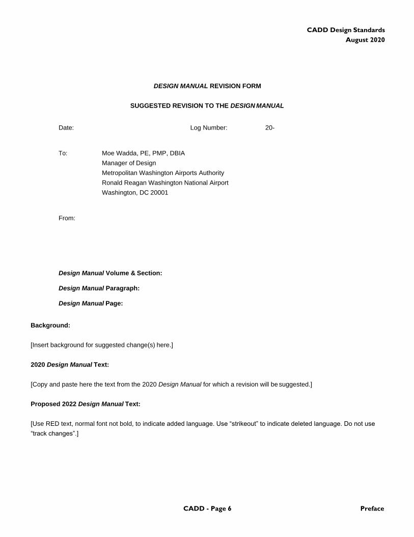
DESIGN MANUAL REVISION FORM
SUGGESTED REVISION TO THE DESIGN MANUAL
Date: Log Number: 20-
To: Moe Wadda, PE, PMP, DBIA
Manager of Design
Metropolitan Washington Airports Authority
Ronald Reagan Washington National Airport
Washington, DC 20001
From:
Design Manual Volume & Section:
Design Manual Paragraph:
Design Manual Page:
Background:
[Insert background for suggested change(s) here.]
2020 Design Manual Text:
[Copy and paste here the text from the 2020 Design Manual for which a revision will be suggested.]
Proposed 2022 Design Manual Text:
[Use RED text, normal font not bold, to indicate added language. Use “strikeout” to indicate deleted language. Do not use
“track changes”.]
CADD/GIS/BIM - Page 7 Table of Contents
CADD Design Standards
August 2020
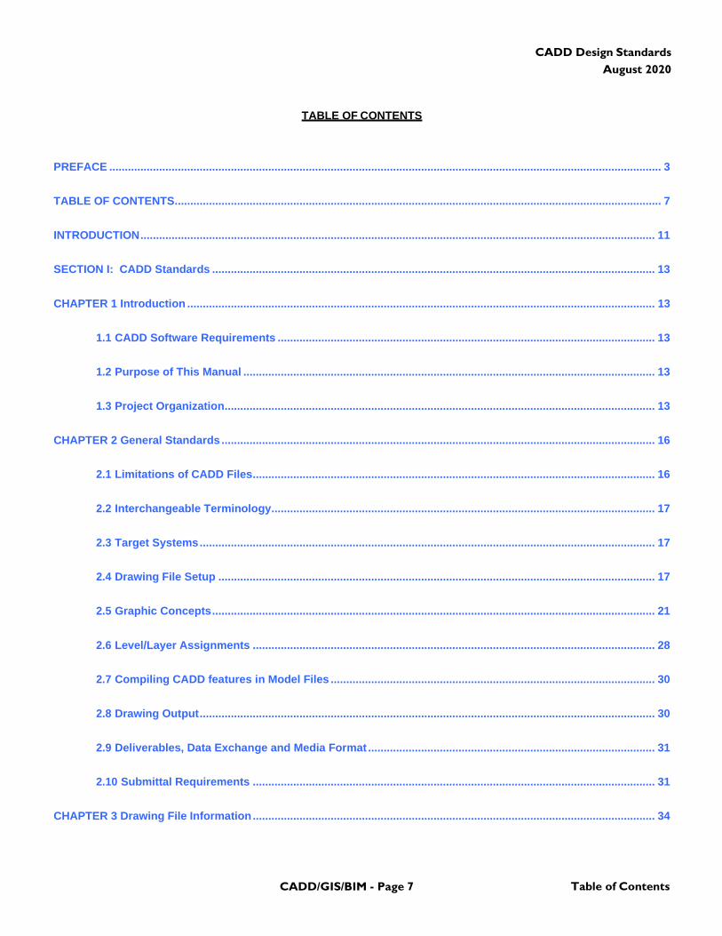
TABLE OF CONTENTS
PREFACE ................................................................................................................................................................................. 3
TABLE OF CONTENTS ............................................................................................................................................................ 7
INTRODUCTION ..................................................................................................................................................................... 11
SECTION I: CADD Standards .............................................................................................................................................. 13
CHAPTER 1 Introduction ...................................................................................................................................................... 13
1.1 CADD Software Requirements ......................................................................................................................... 13
1.2 Purpose of This Manual .................................................................................................................................... 13
1.3 Project Organization.......................................................................................................................................... 13
CHAPTER 2 General Standards ........................................................................................................................................... 16
2.1 Limitations of CADD Files ................................................................................................................................. 16
2.2 Interchangeable Terminology ........................................................................................................................... 17
2.3 Target Systems .................................................................................................................................................. 17
2.4 Drawing File Setup ............................................................................................................................................ 17
2.5 Graphic Concepts .............................................................................................................................................. 21
2.6 Level/Layer Assignments ................................................................................................................................. 28
2.7 Compiling CADD features in Model Files ........................................................................................................ 30
2.8 Drawing Output .................................................................................................................................................. 30
2.9 Deliverables, Data Exchange and Media Format ............................................................................................ 31
2.10 Submittal Requirements ................................................................................................................................. 31
CHAPTER 3 Drawing File Information ................................................................................................................................. 34
CADD/GIS/BIM - Page 8 Table of Contents
CADD Design Standards
August 2020
3.1 Naming Conventions ......................................................................................................................................... 34
3.2 Standard Sheet Formats (Cover Sheet and Title Block Sheet) ..................................................................... 34
3.3 Drawing Preparation/Arrangement .................................................................................................................. 34
3.4 Quality Check (QC) CADD Checklist ................................................................................................................ 34
3.5 Addenda Sketches ............................................................................................................................................. 34
CHAPTER 4 Model File Level/Layer Assignment Tables ................................................................................................... 51
4.1 General ............................................................................................................................................................... 51
4.2 Naming Conventions – Model Files and Level/Layer Tables ......................................................................... 51
4.3 Level/Layer Assignment Tables – Model Files ............................................................................................... 54
4.4 Assignment Tables ............................................................................................................................................ 56
4.5 Hazardous Materials .......................................................................................................................................... 59
4.6 Surveying/Mapping............................................................................................................................................ 64
4.7 Geotechnical .................................................................................................................................................... 120
4.8 Civil ................................................................................................................................................................... 127
4.9 Landscape ........................................................................................................................................................ 197
4.10 Structural Buildings ...................................................................................................................................... 202
4.11 Structural Civil ............................................................................................................................................... 214
4.12 Architectural ................................................................................................................................................... 226
4.13 Interiors .......................................................................................................................................................... 236
4.14 Fire Protection ............................................................................................................................................... 245
4.15 Fire Alarm System ......................................................................................................................................... 252
4.16 Plumbing ........................................................................................................................................................ 256
CADD/GIS/BIM - Page 9 Table of Contents
CADD Design Standards
August 2020
4.17 Mechanical ..................................................................................................................................................... 261
4.18 Electrical ......................................................................................................................................................... 280
4.19 Communications ............................................................................................................................................ 296
4.20 Baggage Handling System ........................................................................................................................... 301
4.21 Security & Access Control System .............................................................................................................. 306
4.22 Public Information System ........................................................................................................................... 312
4.23 Aviation Information System ........................................................................................................................ 316
4.24 Electronic Monitoring System ...................................................................................................................... 318
CHAPTER 5 Sheet File Level/Layer Assignment Tables ................................................................................................. 323
5.1 General ............................................................................................................................................................. 324
5.2 Hazardous Materials ........................................................................................................................................ 325
5.3 Survey/Mapping ............................................................................................................................................... 326
5.4 Geotechnical .................................................................................................................................................... 327
5.5 Civil ................................................................................................................................................................... 328
5.6 Landscape ........................................................................................................................................................ 329
5.7 Structural .......................................................................................................................................................... 330
5.8 Structural Civil ................................................................................................................................................. 331
5.9 Architectural..................................................................................................................................................... 332
5.10 Interiors .......................................................................................................................................................... 333
5.11 Fire Protection ............................................................................................................................................... 334
5.12 Fire Alarm System ......................................................................................................................................... 335
5.13 Plumbing ........................................................................................................................................................ 336
CADD/GIS/BIM - Page 10 Table of Contents
CADD Design Standards
August 2020
5.14 Mechanical ..................................................................................................................................................... 337
5.15 Electrical ......................................................................................................................................................... 338
5.16 Communications ............................................................................................................................................ 339
5.17 Baggage Handling System ........................................................................................................................... 340
5.18 Security & Access Control Systems ............................................................................................................ 341
5.19 Public Information Systems ......................................................................................................................... 342
5.20 Aviation Information Systems ...................................................................................................................... 343
5.21 Electronic Monitoring Systems .................................................................................................................... 344
CHAPTER 6 CADD Symbols ............................................................................................................................................... 346
CHAPTER 7 References and Support Files ...................................................................................................................... 348
7.1 Abbreviations ................................................................................................................................................... 348
7.2 Basic Electronic Layout Files ......................................................................................................................... 348
7.3 References ....................................................................................................................................................... 349
SECTION II: GIS .................................................................................................................................................................. 351
CHAPTER 1 Geographic Information Systems (GIS)Standards and Submittal Requirements.................................... 351
1.1 Applicability ..................................................................................................................................................... 351
1.2 Creating GIS Features from CADD Model Files: ........................................................................................... 351
1.3 Structure and Organization of GIS Submittals: ............................................................................................ 351
1.4 Requirements for Ensuring High Quality GIS Deliverables ......................................................................... 353
SECTION III: BIM .................................................................................................................................................................. 357
CHAPTER 1 Building Information Modeling (BIM) Standards and Submittal Requirements ....................................... 359
1.1 Introduction ...................................................................................................................................................... 359
CADD/GIS/BIM - Page 11 Table of Contents
CADD Design Standards
August 2020
CHAPTER 2 Purpose of BIM ............................................................................................................................................... 359
CHAPTER 3 Applicability of BIM Usage ............................................................................................................................ 359
CHAPTER 4 BIM Projects Workflow .................................................................................................................................. 359
CHAPTER 5 BIM Execution Plan ........................................................................................................................................ 359
5.1 General Procedures and Methods ................................................................................................................. 359
5.2 Levels of Detail ................................................................................................................................................ 359
5.3 Shared Workflows ........................................................................................................................................... 360
5.4 BIM Execution Plan Requirements ................................................................................................................ 360
CHAPTER 6 Software Version............................................................................................................................................ 361
CHAPTER 7 Model Level of Development ....................................................................................................................... 361
CHAPTER 8 Coordinate Systems ...................................................................................................................................... 363
8.1 Authority Survey Control Document ............................................................................................................. 363
8.2 MWAA Geospatial Coordinate System .......................................................................................................... 363
CHAPTER 9 Linking files .................................................................................................................................................... 363
CHAPTER 10 Project Deliverables ..................................................................................................................................... 363
CHAPTER 11 BIM Standards Review ................................................................................................................................ 363
CHAPTER 12 MWAA BIM Support Files and Libraries .................................................................................................... 363
CHAPTER 13 Project Folder Structure .............................................................................................................................. 363
CHAPTER 14 MWAA Revit Templates ............................................................................................................................... 363
CHAPTER 15 Quality Control and Clash Detection ......................................................................................................... 363
15.1 Clash Detections............................................................................................................................................ 363
15.2 Milestone Submissions ................................................................................................................................. 363

CADD/GIS/BIM - Page 12 Table of Contents
CADD Design Standards
August 2020
15.3 Submittal Reviews ......................................................................................................................................... 364
CHAPTER 16 MWAA Standard Title Sheets and Contract Borders ................................................................................ 364
CHAPTER 17 Disclaimer ..................................................................................................................................................... 364
LIST OF EXHIBITS ............................................................................................................................................................... 363
INDEX ................................................................................................................................................................................... 365
CADD/GIS/BIM - Page 13 Introduction
CADD Design Standards
August 2020
INTRODUCTION
GUIDE TO THIS VOLUME OF THE DESIGN MANUAL
This volume consists of design standards, design criteria, procedures, and products for Ronald Reagan Washington
National Airport and Washington Dulles International Airport and relates to the General CADD/GIS Design
Standards Dulles Corridor Enterprise.
This volume consists of two sections:
Section I CADD Design Standards
Chapter 1: Introduction
Chapter 2: General Standards
Chapter 3: Drawing File Information
Chapter 4: Model File Level/Layer Assignment Tables
Chapter 5: Sheet File Level/Layer Assignment Tables
Chapter 6: CADD Symbols
Chapter 7 References and Support Files
Section II GIS
Chapter 1: Geographic Information Systems (GIS) Standard
CADD/GIS/BIM - Page 14 Introduction
CADD Design Standards
August 2020
(This Page Blank)
CADD Design Standards
August 2020
CADD Standards CADD - Page 15 Section I
SECTION I: CADD Standards
CHAPTER 1 Introduction
This Manual is prepared for use by the Metropolitan
Washington Airports Authority (the Authority). The Authority
has elected to provide consultants with a resource made
available electronically which contains the title sheet, cover
sheet, project grid and other support files to assist in
creating the design files and to comply with the Authority
CADD Standards. These title and cover sheets have been
standardized by the Authority and must match the
distributed formats in all respects (font style, font weights,
line weights, etc.).
The list of CADD support files provided by the Authority to
the A/E is given in Paragraph 7.2. Additionally, a “read me”
file is also included for instructions on how to properly utilize
the support files. This information can be found on the
Design Manual CD-ROM in a subdirectory located at…
(CD-ROM drive letter):/CAD. You may also obtain this
information by contacting the Project Contracting Officer.
Appendix 3, CADD Standards, is currently undergoing
substantial revision by the Authority. Designers shall
consult with the Authority Design Department before
undertaking any design work incorporating CADD for the
Authority.
1.1 Purpose of This Manual
1.2.1 General: The purpose of this Manual is to
establish uniform standard policies and procedures for
the design and drafting work within a CADD
environment. The basic engineering and drafting
techniques are not discussed.
1.2.2 Policies: The policies established herein are for
the information and guidance of Architects/Engineers
who perform design services to support the Authority and
Authority tenants. Any special condition which may
require a variation from these requirements is subject to
prior approval by the Authority.
1.2.3 Standards: It is important to note that these
standards are not static and will continue to evolve as the
Authority requirements and technology change. The basic
philosophy of these standards is to:
1.2.3.1 Contract Documents: Create accurate CADD
generated Contract Documents.
1.2.3.2 Standardized Drawing Formats: Provide
standardized drawing format to assist the owner in
maintaining facilities for an extended period of time.
1.2 CADD Software Requirements
1.2.1 General: The Authority accepts submittals in either
of two formats, depending on the discipline. For each
format, the files must be “native” formats, fully functional,
editable, and completely useable within the respective
software of creation noted below. It is not acceptable to
create drawings on any other software other than noted
below and files may not be translated from any other
software into these formats. Formats are Bentley
Microstation or AutoCad, including Revit. Current
supported versions only.
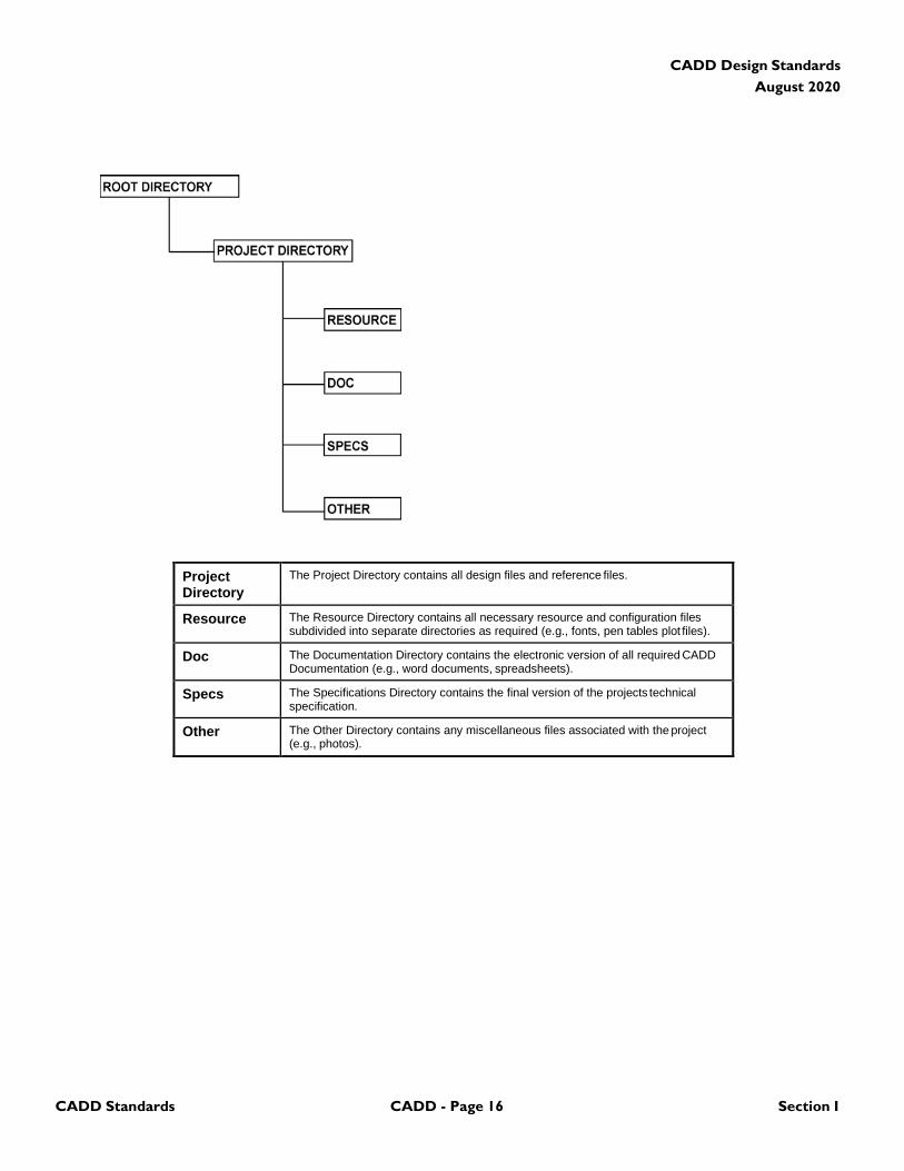
1.3 Project Organization
1.3.1 Project Structure: This section defines the project
directory structure to be used for CADD drawings and
various other file types. The primary Project Directory name
should contain the following sub-directories:
CADD Design Standards
August 2020
CADD Standards CADD - Page 16 Section I
Project Directory
The Project Directory contains all design files and reference files.
Resource The Resource Directory contains all necessary resource and configuration files subdivided into separate directories as required (e.g., fonts, pen tables plot files).
Doc The Documentation Directory contains the electronic version of all required CADD Documentation (e.g., word documents, spreadsheets).
Specs The Specifications Directory contains the final version of the projects technical specification.
Other The Other Directory contains any miscellaneous files associated with the project (e.g., photos).
CADD Design Standards
August 2020
CADD Standards CADD - Page 17 Section I
(This Page Blank)
CADD Design Standards
August 2020
CADD Standards CADD - Page 18 Section I
CHAPTER 2 General Standards
2.1 Limitations of CADD Files
2.1.1 General: CADD files can contain text, primitive
elements (lines, areas, and shapes), or grouped elements
(cells/blocks, graphic groups, or complex elements).
AutoCAD drawing files shall not contain the following
elements: Shape symbol fonts, Rtext, OLE frame, Ray,
Xline, Proxy objects.
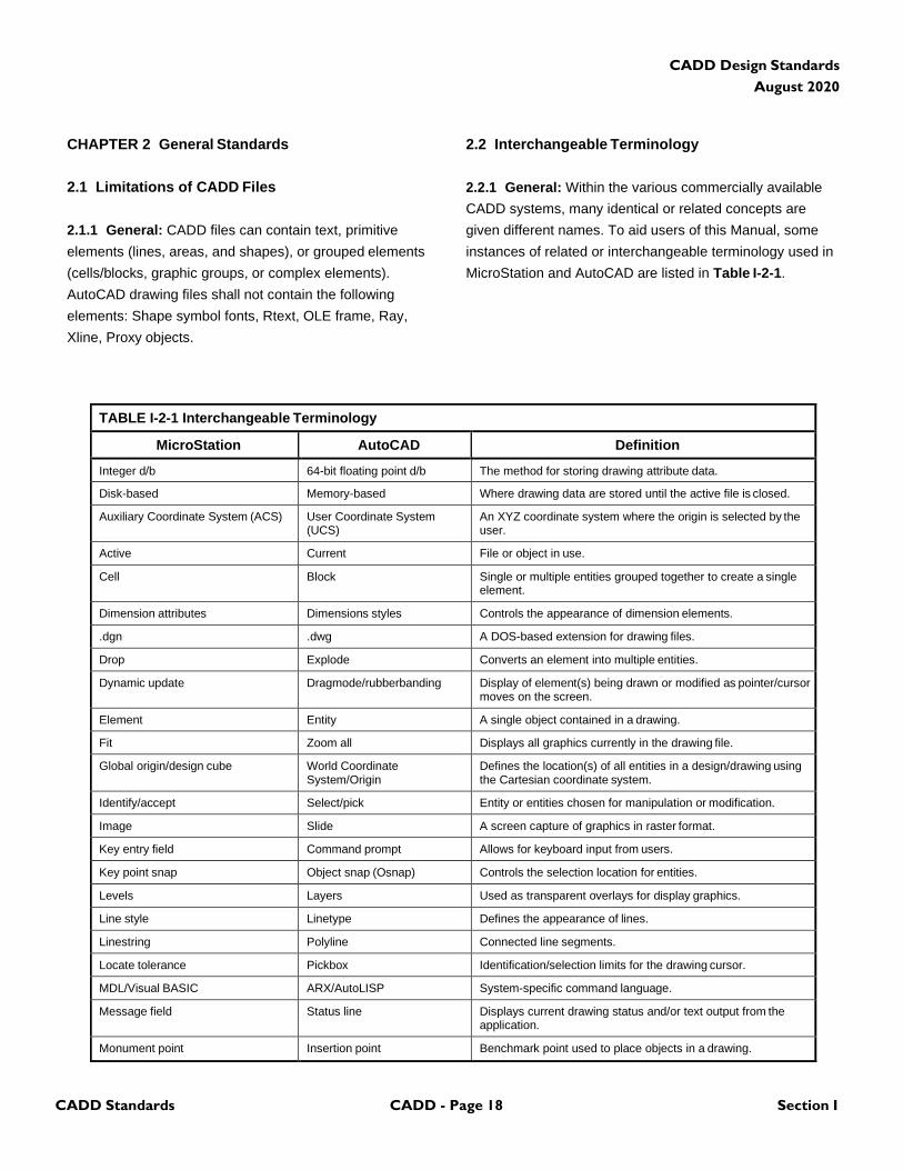
2.2 Interchangeable Terminology
2.2.1 General: Within the various commercially available
CADD systems, many identical or related concepts are
given different names. To aid users of this Manual, some
instances of related or interchangeable terminology used in
MicroStation and AutoCAD are listed in Table I-2-1.
TABLE I-2-1 Interchangeable Terminology
MicroStation AutoCAD Definition
Integer d/b 64-bit floating point d/b The method for storing drawing attribute data.
Disk-based Memory-based Where drawing data are stored until the active file is closed.
Auxiliary Coordinate System (ACS) User Coordinate System (UCS)
An XYZ coordinate system where the origin is selected by the user.
Active Current File or object in use.
Cell Block Single or multiple entities grouped together to create a single element.
Dimension attributes Dimensions styles Controls the appearance of dimension elements.
.dgn .dwg A DOS-based extension for drawing files.
Drop Explode Converts an element into multiple entities.
Dynamic update Dragmode/rubberbanding Display of element(s) being drawn or modified as pointer/cursor moves on the screen.
Element Entity A single object contained in a drawing.
Fit Zoom all Displays all graphics currently in the drawing file.
Global origin/design cube World Coordinate System/Origin
Defines the location(s) of all entities in a design/drawing using the Cartesian coordinate system.
Identify/accept Select/pick Entity or entities chosen for manipulation or modification.
Image Slide A screen capture of graphics in raster format.
Key entry field Command prompt Allows for keyboard input from users.
Key point snap Object snap (Osnap) Controls the selection location for entities.
Levels Layers Used as transparent overlays for display graphics.
Line style Linetype Defines the appearance of lines.
Linestring Polyline Connected line segments.
Locate tolerance Pickbox Identification/selection limits for the drawing cursor.
MDL/Visual BASIC ARX/AutoLISP System-specific command language.
Message field Status line Displays current drawing status and/or text output from the application.
Monument point Insertion point Benchmark point used to place objects in a drawing.
CADD Design Standards
August 2020
CADD Standards CADD - Page 19 Section I
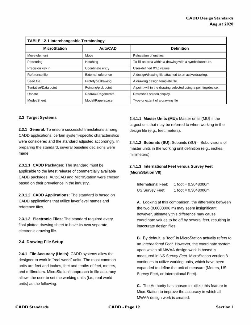
TABLE I-2-1 Interchangeable Terminology
MicroStation AutoCAD Definition
Move element Move Relocation of entities.
Patterning Hatching To fill an area within a drawing with a symbolic texture.
Precision key in Coordinate entry User-defined XYZ values.
Reference file External reference A design/drawing file attached to an active drawing.
Seed file Prototype drawing A drawing design template file.
Tentative/Data point Pointing/pick point A point within the drawing selected using a pointing device.
Update Redraw/Regenerate Refreshes screen display.
Model/Sheet Model/Paperspace Type or extent of a drawing file
2.3 Target Systems
2.3.1 General: To ensure successful translations among
CADD applications, certain system-specific characteristics
were considered and the standard adjusted accordingly. In
preparing the standard, several baseline decisions were
made:
2.3.1.1 CADD Packages: The standard must be
applicable to the latest release of commercially available
CADD packages. AutoCAD and MicroStation were chosen
based on their prevalence in the industry.
2.3.1.2 CADD Applications: The standard is based on
CADD applications that utilize layer/level names and
reference files.
2.3.1.3 Electronic Files: The standard required every
final plotted drawing sheet to have its own separate
electronic drawing file.
2.4 Drawing File Setup
2.4.1 File Accuracy (Units): CADD systems allow the
designer to work in “real world” units. The most common
units are feet and inches, feet and tenths of feet, meters,
and millimeters. MicroStation’s approach to file accuracy
allows the user to set the working units (i.e., real world
units) as the following:
2.4.1.1 Master Units (MU): Master units (MU) = the
largest unit that may be referred to when working in the
design file (e.g., feet, meters).
2.4.1.2 Subunits (SU): Subunits (SU) = Subdivisions of
master units in the working unit definition (e.g., inches,
millimeters).
2.4.1.3 International Feet versus Survey Feet
(MicroStation V8)
International Feet: 1 foot = 0.3048000m
US Survey Feet: 1 foot = 0.3048006m
A. Looking at this comparison, the difference between
the two (0.0000006 m) may seem insignificant;
however, ultimately this difference may cause
coordinate values to be off by several feet, resulting in
inaccurate design files.
B. By default, a “foot” in MicroStation actually refers to
an International Foot. However, the coordinate system
upon which all MWAA design work is based is
measured in US Survey Feet. MicroStation version 8
continues to utilize working units, which have been
expanded to define the unit of measure (Meters, US
Survey Feet, or International Feet).
C. The Authority has chosen to utilize this feature in
MicroStation to improve the accuracy in which all
MWAA design work is created.
CADD Design Standards
August 2020
CADD Standards CADD - Page 20 Section I
D. While this is an important operational improvement,
it has significant consequences. Therefore, care must
be exercised to ensure and maintain the integrity of
MicroStation DGN files with respect to the units of
measure. In MicroStation v8, a workspace is
accompanied by a custom units definition file (units.
def), which defines the units of measure. To enable,
scroll down the units.def file to the section English
units (based on U.S. Survey Foot) and delete the # in
front of #sf,ft, which will allow for the selection of
Survey Feet from the Working Units box the next time
MicroStation is started.
2.4.2 Origin: Positioned within every electronic drawing
file is an origin (“global origin” in MicroStation and “origin” in
AutoCAD). The origin of a drawing file is important because
it serves as the point of reference from which all other
elements are located. The benefit of standardizing the
location of the origin of a drawing is most notable in the use
of reference files. Also, in certain disciplines, particularly
mapping, the location of the origin determines the available
drawing area (MicroStation only). A standardized origin is
also helpful when translating files between CADD
applications. The global origin for all CADD files, if not
already set, shall be set to 0,0,0 by keying in GO=0,0,0 at
the command prompt. This is not necessary in in AutoCAD.
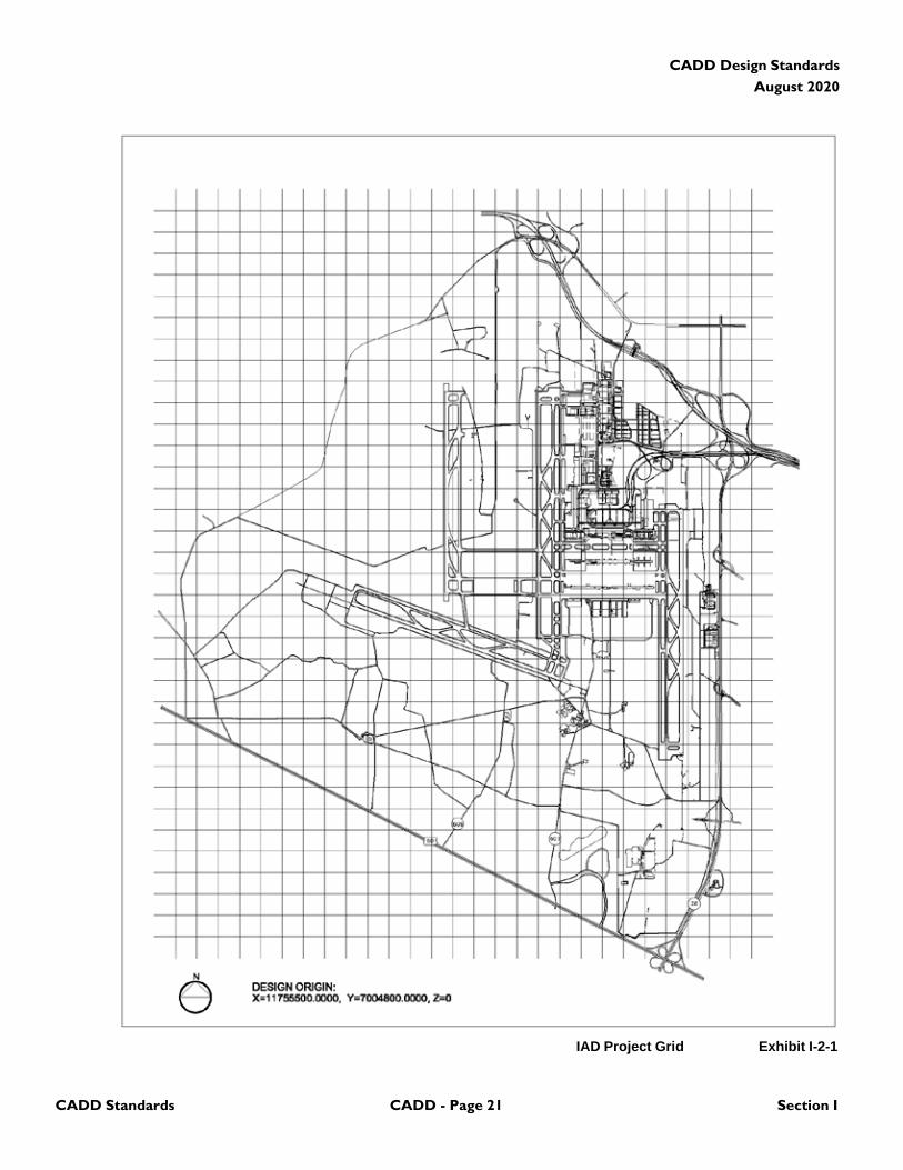
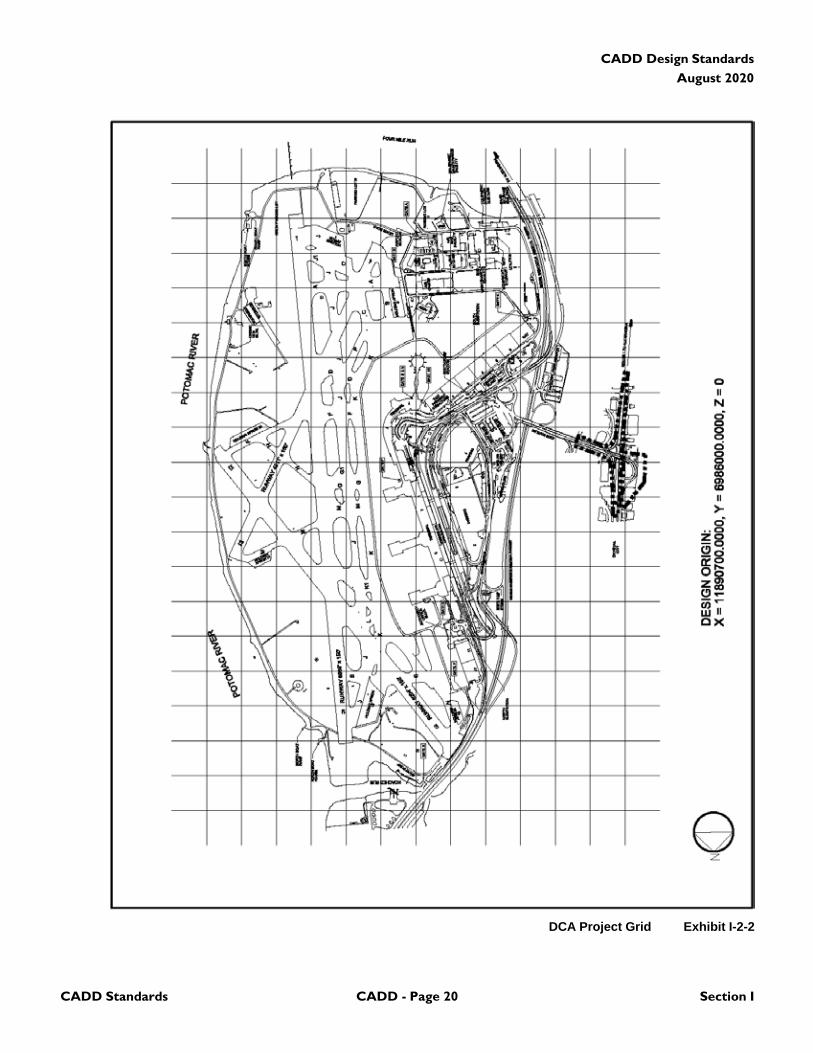
2.4.3 Design Origin: The Design Origin of the airport grid
file has been set according to Exhibit I-2-1 and
Exhibit I-2-2 for each airport respectively and based on the
NAD83 VA State Plane. The user is to key in X, Y locations
such that they are equivalent to the true geometric location
of the data based on the airport grid. All elements except
contours and spot elevations shall be placed on the Z plane
of zero. Contours and spot elevations shall be placed on
the Z plane representing the elevation.
2.4.4 Grid System: All civil drawings must be created
using the Decimal System and the Airport Grid System
based on NAD83 VA State Plane, which show all measures
in decimal feet. All architectural plans using architectural
measures shall reference a minimum of three (3) plan
points to the Airport Grid System. This standard grid system
is outlined in Exhibit I-2-1 and Exhibit I-2-2. The grid
systems are detailed within the most recent version of the
Ronald Reagan Washington National Airport Survey control
network “To-Reach” Descriptions. The description for
Ronald Reagan National Airport is included on the Design
Manual CD-ROM. The Description for Washington Dulles
International Airport can be obtained by contacting the
Manager of the Washington Dulles International Airport
Engineering Division at 703-572-2885.
2.4.5 Model Files and Sheet Files: Two distinct types of
CADD files are addressed in this standard, model files and
sheet files. A model file contains the physical components
of a building (e.g., columns, walls, windows, ductwork,
piping, etc.). Model files are drawn at full scale and typically
represent plans, elevations, section, etc. A sheet file is
synonymous with a plotted CADD drawing file. A sheet file
is a selected view or portion of the model file(s) within a
border sheet. In Microstation, sheet files are usually plotted
at a particular scale, since the border sheet is scaled up to
fit around the full scale model files. Sheet files in AutoCAD
are usually plotted at full scale, since the title border is
inserted or referenced in Layout Space at 1:1 and the sheet
content is scaled down through viewports. In other words,
a sheet file is a “ready-to-plot” CADD file. A sheet file is the
combination of referenced model files with sheet-specific
text/symbols to create a final “ready-to-plot” CADD file.
CADD Design Standards
August 2020
CADD Standards CADD - Page 21 Section I
IAD Project Grid Exhibit I-2-1
CADD Design Standards
August 2020
DCA Project Grid Exhibit I-2-2
CADD Standards CADD - Page 20 Section I
CADD Design Standards
August 2020
CADD Standards CADD - Page 23 Section I
2.5 Graphic Concepts
2.5.1 Presentation Graphics: The first step in
establishing an effective CADD standard is the
development of a uniform approach to presentation
graphics. Presentation graphics typically consist of drawing
elements such as lines, arcs, shapes, text, and their
attributes (line color, line width, and line style). This Manual
presents brief overviews of the characteristics of
presentation graphics and the philosophy used to
standardize them.
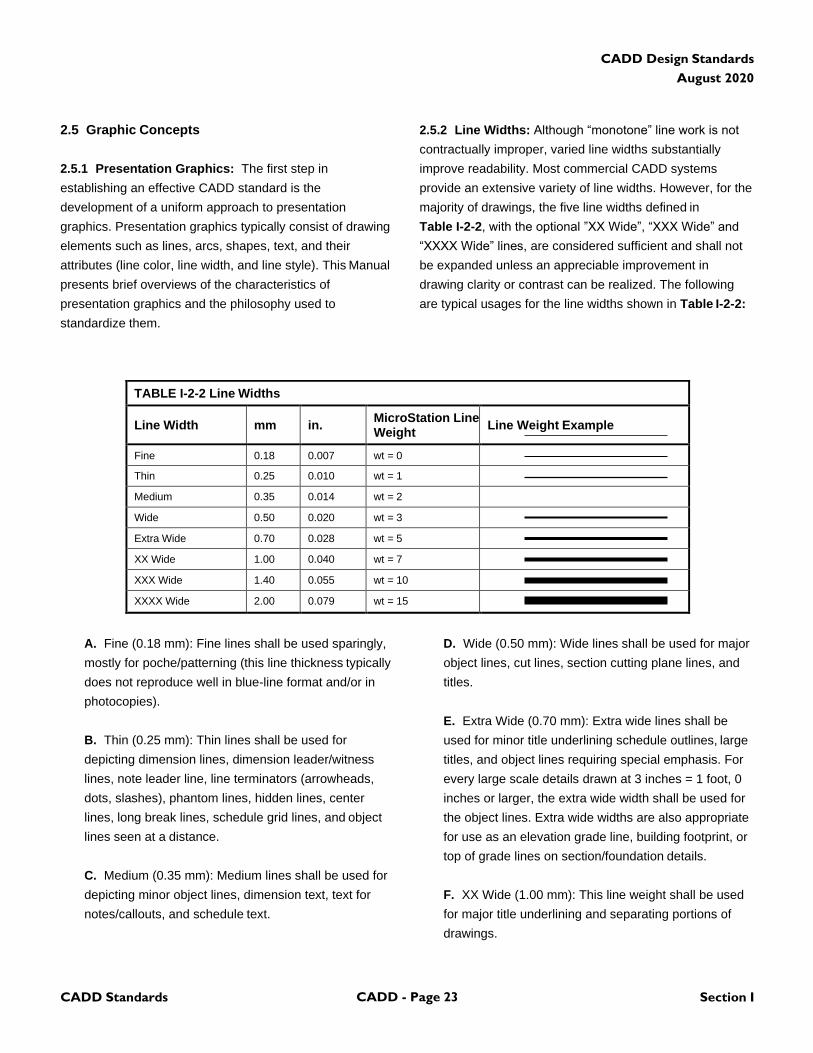
2.5.2 Line Widths: Although “monotone” line work is not
contractually improper, varied line widths substantially
improve readability. Most commercial CADD systems
provide an extensive variety of line widths. However, for the
majority of drawings, the five line widths defined in
Table I-2-2, with the optional ”XX Wide”, “XXX Wide” and
“XXXX Wide” lines, are considered sufficient and shall not
be expanded unless an appreciable improvement in
drawing clarity or contrast can be realized. The following
are typical usages for the line widths shown in Table I-2-2:
A. Fine (0.18 mm): Fine lines shall be used sparingly,
mostly for poche/patterning (this line thickness typically
does not reproduce well in blue-line format and/or in
photocopies).
B. Thin (0.25 mm): Thin lines shall be used for
depicting dimension lines, dimension leader/witness
lines, note leader line, line terminators (arrowheads,
dots, slashes), phantom lines, hidden lines, center
lines, long break lines, schedule grid lines, and object
lines seen at a distance.
C. Medium (0.35 mm): Medium lines shall be used for
depicting minor object lines, dimension text, text for
notes/callouts, and schedule text.
D. Wide (0.50 mm): Wide lines shall be used for major
object lines, cut lines, section cutting plane lines, and
titles.
E. Extra Wide (0.70 mm): Extra wide lines shall be
used for minor title underlining schedule outlines, large
titles, and object lines requiring special emphasis. For
every large scale details drawn at 3 inches = 1 foot, 0
inches or larger, the extra wide width shall be used for
the object lines. Extra wide widths are also appropriate
for use as an elevation grade line, building footprint, or
top of grade lines on section/foundation details.
F. XX Wide (1.00 mm): This line weight shall be used
for major title underlining and separating portions of
drawings.
TABLE I-2-2 Line Widths
Line Width
mm
in. MicroStation Line Weight
Line Weight Example
Fine 0.18 0.007 wt = 0 Thin 0.25 0.010 wt = 1 Medium 0.35 0.014 wt = 2 Wide 0.50 0.020 wt = 3 Extra Wide 0.70 0.028 wt = 5 XX Wide 1.00 0.040 wt = 7 XXX Wide 1.40 0.055 wt = 10 XXXX Wide 2.00 0.079 wt = 15
CADD Design Standards
August 2020
CADD Standards CADD - Page 24 Section I
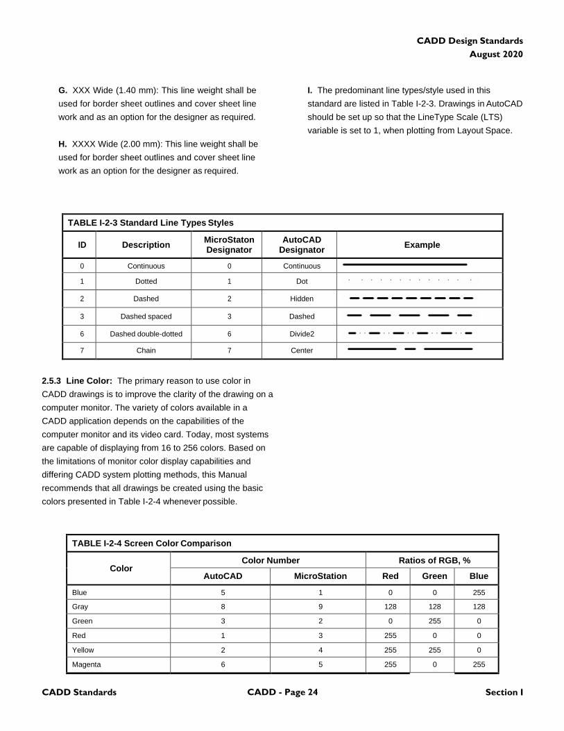
G. XXX Wide (1.40 mm): This line weight shall be
used for border sheet outlines and cover sheet line
work and as an option for the designer as required.
H. XXXX Wide (2.00 mm): This line weight shall be
used for border sheet outlines and cover sheet line
work as an option for the designer as required.
I. The predominant line types/style used in this
standard are listed in Table I-2-3. Drawings in AutoCAD
should be set up so that the LineType Scale (LTS)
variable is set to 1, when plotting from Layout Space.
TABLE I-2-3 Standard Line Types Styles
ID
Description MicroStaton Designator
AutoCAD Designator
Example
0 Continuous 0 Continuous
1 Dotted 1 Dot
2 Dashed 2 Hidden
3 Dashed spaced 3 Dashed
6 Dashed double-dotted 6 Divide2
7 Chain 7 Center
2.5.3 Line Color: The primary reason to use color in
CADD drawings is to improve the clarity of the drawing on a
computer monitor. The variety of colors available in a
CADD application depends on the capabilities of the
computer monitor and its video card. Today, most systems
are capable of displaying from 16 to 256 colors. Based on
the limitations of monitor color display capabilities and
differing CADD system plotting methods, this Manual
recommends that all drawings be created using the basic
colors presented in Table I-2-4 whenever possible.
TABLE I-2-4 Screen Color Comparison
Color
Color Number Ratios of RGB, %
AutoCAD MicroStation Red Green Blue
Blue 5 1 0 0 255
Gray 8 9 128 128 128
Green 3 2 0 255 0
Red 1 3 255 0 0
Yellow 2 4 255 255 0
Magenta 6 5 255 0 255
CADD Design Standards
August 2020
CADD Standards CADD - Page 25 Section I
TABLE I-2-4 Screen Color Comparison
Cyan 4 7 0 255 255
White 7 0 255 255 255
Note: Color numbers for AutoCAD and MicroStation were taken from default color tables.
Note: The recommended colors are best viewed on a monitor with a black background.
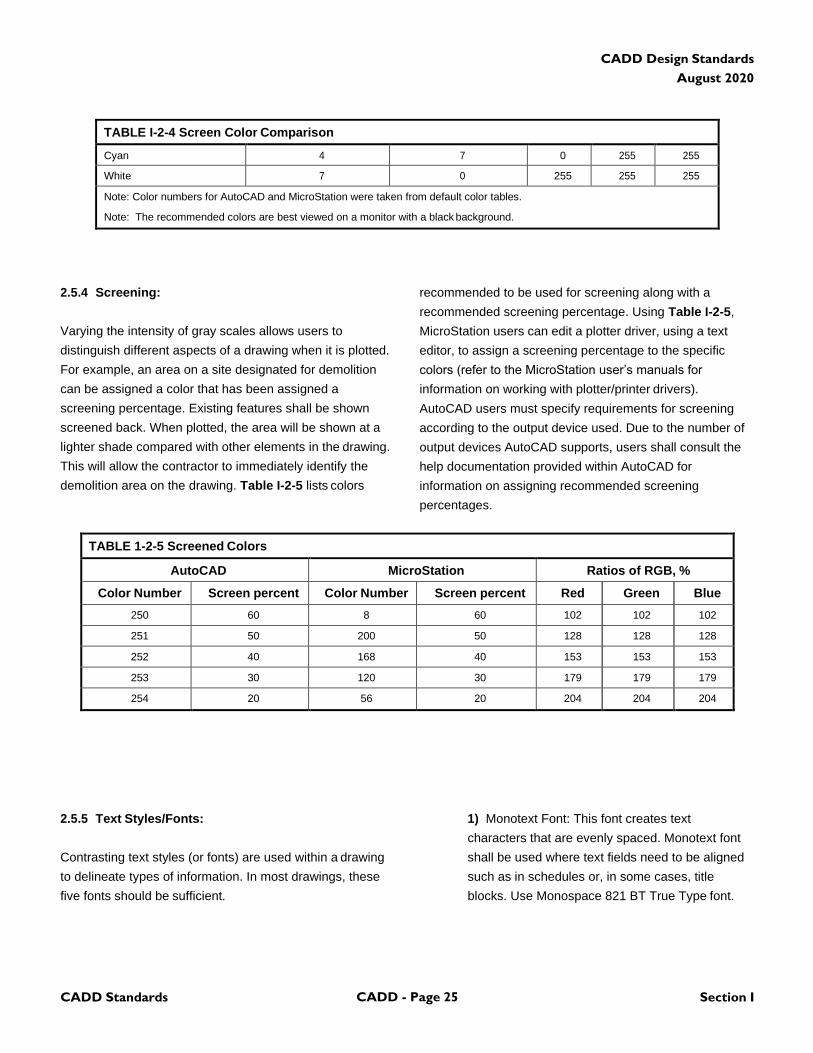
2.5.4 Screening:
Varying the intensity of gray scales allows users to
distinguish different aspects of a drawing when it is plotted.
For example, an area on a site designated for demolition
can be assigned a color that has been assigned a
screening percentage. Existing features shall be shown
screened back. When plotted, the area will be shown at a
lighter shade compared with other elements in the drawing.
This will allow the contractor to immediately identify the
demolition area on the drawing. Table I-2-5 lists colors
recommended to be used for screening along with a
recommended screening percentage. Using Table I-2-5,
MicroStation users can edit a plotter driver, using a text
editor, to assign a screening percentage to the specific
colors (refer to the MicroStation user’s manuals for
information on working with plotter/printer drivers).
AutoCAD users must specify requirements for screening
according to the output device used. Due to the number of
output devices AutoCAD supports, users shall consult the
help documentation provided within AutoCAD for
information on assigning recommended screening
percentages.
TABLE 1-2-5 Screened Colors
AutoCAD MicroStation Ratios of RGB, %
Color Number Screen percent Color Number Screen percent Red Green Blue
250 60 8 60 102 102 102
251 50 200 50 128 128 128
252 40 168 40 153 153 153
253 30 120 30 179 179 179
254 20 56 20 204 204 204
2.5.5 Text Styles/Fonts:
Contrasting text styles (or fonts) are used within a drawing
to delineate types of information. In most drawings, these
five fonts should be sufficient.
1) Monotext Font: This font creates text
characters that are evenly spaced. Monotext font
shall be used where text fields need to be aligned
such as in schedules or, in some cases, title
blocks. Use Monospace 821 BT True Type font.
CADD Design Standards
August 2020
CADD Standards CADD - Page 26 Section I
2) Proportional Font: This font creates text where
the characters are proportionally spaced. It is
appropriate for general notes, labels, or title blocks.
Use Arial True Type font.
3) Slanted Font: A slanted font is used where text
needs to be easily distinguished from other text.
Use Arial True Type font with the Slant Angle set to
15 deg to achieve the American Standard slope of
2 in 5 (68.2 deg).
4) Filled Font: Filled fonts are used primarily for
titles and on cover sheets. Use Ariblk (Arial Black)
True Type font.
5) Outline Font: When a pen plotter is used for
final output, the outline font is used as a substitute
for filled fonts for major titles such as cover sheet
information to save plotting time. Use Swissko
(Swiss 721 Black Outline) True Type font.
6) NOTE: The fonts for the cover sheets and
border sheets in the CADD support files provided
by the Authority shall not be changed or modified.
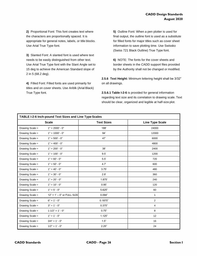
2.5.6 Text Height: Minimum lettering height shall be 3/32”
on all drawings.
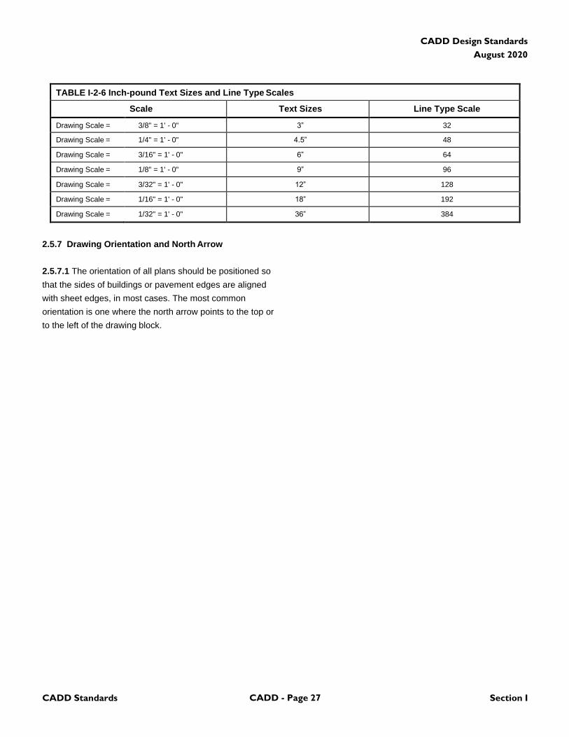
2.5.6.1 Table I-2-6 is provided for general information
regarding text size and its correlation to drawing scale. Text
should be clear, organized and legible at half-size plot.
TABLE I-2-6 Inch-pound Text Sizes and Line Type Scales
Scale Text Sizes Line Type Scale
Drawing Scale = 1" = 2000' - 0" 188’ 24000
Drawing Scale = 1" = 1000' - 0" 94’ 12000
Drawing Scale = 1" = 500' - 0" 47’ 6000
Drawing Scale = 1" = 400' - 0" 4800
Drawing Scale = 1" = 200' - 0" 38’ 2400
Drawing Scale = 1" = 100' - 0" 9.5’ 1200
Drawing Scale = 1" = 60' - 0" 5.5’ 720
Drawing Scale = 1" = 50' - 0" 4.7’ 600
Drawing Scale = 1" = 40' - 0" 3.75’ 480
Drawing Scale = 1" = 30' - 0" 2.8’ 360
Drawing Scale = 1" = 20' - 0" 1.875’ 240
Drawing Scale = 1" = 10' - 0" 0.95’ 120
Drawing Scale = 1" = 5' - 0" 5.625” 60
Drawing Scale = 12” = 1’ – 0” or FULL SIZE 0.094” 1
Drawing Scale = 6" = 1' - 0" 0.1875” 2
Drawing Scale = 3" = 1' - 0" 0.375” 4
Drawing Scale = 1-1/2" = 1' - 0" 0.75” 8
Drawing Scale = 1" = 1' - 0" 1.125” 12
Drawing Scale = 3/4" = 1' - 0" 1.5” 16
Drawing Scale = 1/2" = 1' - 0" 2.25” 24
CADD Design Standards
August 2020
CADD Standards CADD - Page 27 Section I
TABLE I-2-6 Inch-pound Text Sizes and Line Type Scales
Scale Text Sizes Line Type Scale
Drawing Scale = 3/8" = 1' - 0" 3” 32
Drawing Scale = 1/4" = 1' - 0" 4.5” 48
Drawing Scale = 3/16" = 1' - 0" 6” 64
Drawing Scale = 1/8" = 1' - 0" 9” 96
Drawing Scale = 3/32" = 1' - 0" 12” 128
Drawing Scale = 1/16" = 1' - 0" 18” 192
Drawing Scale = 1/32" = 1' - 0" 36” 384
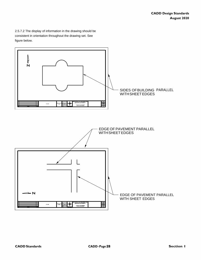
2.5.7 Drawing Orientation and North Arrow
2.5.7.1 The orientation of all plans should be positioned so
that the sides of buildings or pavement edges are aligned
with sheet edges, in most cases. The most common
orientation is one where the north arrow points to the top or
to the left of the drawing block.
CADD - Page 28 Section I CADD Standards
CADD Design Standards
August 2020
2.5.7.2 The display of information in the drawing should be
consistent in orientation throughout the drawing set. See
figure below.
PARALLEL
EDGE OF PAVEMENT PARALLEL WITH SHEET EDGES
EDGE OF PAVEMENT PARALLEL WITH SHEET EDGES
SIDES OF BUILDING WITH SHEET EDGES
CADD - Page 29 Section I CADD Standards
CADD Design Standards
August 2020
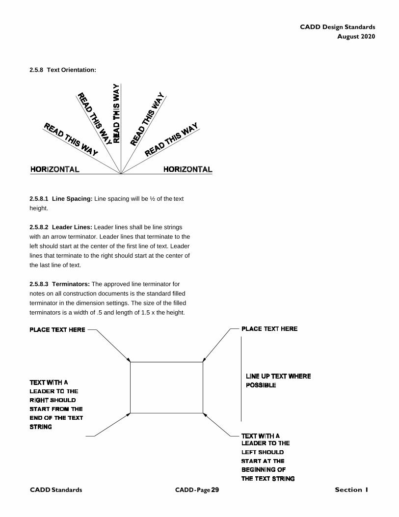
2.5.8 Text Orientation:
2.5.8.1 Line Spacing: Line spacing will be ½ of the text
height.
2.5.8.2 Leader Lines: Leader lines shall be line strings
with an arrow terminator. Leader lines that terminate to the
left should start at the center of the first line of text. Leader
lines that terminate to the right should start at the center of
the last line of text.
2.5.8.3 Terminators: The approved line terminator for
notes on all construction documents is the standard filled
terminator in the dimension settings. The size of the filled
terminators is a width of .5 and length of 1.5 x the height.
CADD - Page 30 Section I CADD Standards
CADD Design Standards
August 2020
2.5.9 Dimension Terminators: The approved line
terminator for dimensions on all construction documents is
the standard filled terminator in the dimension settings. The
size of the filled terminators is a width of .5 and length of
1.5 x the text height.
2.5.10 Abbreviations: Abbreviations used shall conform
to the United States National CAD Standard CSI Uniform
Drawing System Module 5, "Terms and Abbreviations." All
abbreviations used on drawings shall be noted and defined
in an abbreviation list within each discipline’s drawing set.
2.6 Level/Layer Assignments
2.6.1 Levels/Layers: CADD levels or layers are
analogous to overlays in manual drafting systems and
serve to separate graphic elements (lines, shapes, and text)
according to the design discipline they represent. The types
of information represented by individual levels/layers can be
grouped into two (2) primary types: model-specific
information and sheet-specific information. Model-specific
information represents the physical form of a site, a
building, or objects composing a building. This information
is often shared between drawings. Examples include walls,
doors, light fixtures, and room numbers. Model-specific
information may be either literal (e.g., walls) or symbolic
(e.g., electrical outlets). Sheet-specific information may
include notes, annotative symbols, and titles. This type of
information is usually not shared between drawings. To use
and manipulate model-specific and sheet-specific
information effectively, every level/layer must be defined
(standardized) by its name and its use.
2.6.2 Level/Layer Naming Convention: The reuse, not
duplication, of graphic information reduces drawing time
and improves project coordination. The level/layer is the
basic tool used in CADD for managing graphic information.
Level/layer names consist of a two-character Discipline
Designator (e.g., “AR-” for Architectural, “ME-” for
Mechanical), followed by a four-character Major Group
(e.g., “DOOR” for Doors, “LITE” for Lighting Fixtures), and
followed by a four-character Minor Group (e.g.,
AR-WALL-FULL-EXTR for exterior full height walls versus
AR-WALL-FULL-INTR for interior full height walls).
2.6.3 Model Files: Model files represent full-size drawings
of building elements, systems, or information (e.g., the
mechanical HVAC system, the architectural floor plan,
details, and sections) and sheet files represent final plotted
sheets. Model files are used as components in creating
plotted sheet files. The information contained within a
model file for a discipline may be referenced by other
disciplines to create the particular model files or sheet files
for that discipline. A model file can be considered a “work in
progress.” For instance, a mechanical engineer may
reference the architect’s floor plan model file to begin
development of the HVAC ductwork layout model file.
Meanwhile, the architect can continue developing the floor
plan to meet new requirements. Any changes to the floor
plan would be immediately accessible to the mechanical
engineer. The viewing of real-time updates eliminates a
great deal of frustration for other disciplines because it
allows for on-the-spot rather than after-the-fact
modifications.
2.6.4 Level/Layer Assignment Tables - Model Files:
The level/layer assignment tables in Section 4.1 present
the following:
2.6.4.1 Level/Layer Names: The level/layer names
assigned to each model file.
2.6.4.2 Description: A detailed description for each
level/layer.
2.6.4.3 Presentation Graphics: The presentation
graphics associated with each level/layer. This includes the
line style, line width, and color.
2.6.4.4 Annotation Levels/Layers: Users should note
that the following eight level/layers for every model file type
(with the exception of detail model file types) are the same,
the only difference being that the Discipline Designator
changes depending on the discipline for that model file
type. The unique function of these eight annotation
CADD - Page 31 Section I CADD Standards
CADD Design Standards
August 2020
levels/layers is to contain model-specific information that
might not be required by other disciplines. These
levels/layers are as follows with ** representing a Discipline
Designator (e.g., AR-, CV-):
**ANNO-DIMS
Witness/extension lines, dimension terminators and
dimension text.
**ANNO-KEYN
Reference keynotes with associated leaders.
**ANNO-NOTE
General notes and remarks.
**ANNO-NPLT
Non-plotting graphic information.
**ANNO-PATT
Miscellaneous patterning and hatching.
**ANNO-SYMB
Miscellaneous symbols.
**ANNO-TEXT
Miscellaneous text and callouts with associated leaders.
**ANNO-REFR
An AutoCAD user-specific layer for use in attachment of
external references (i.e., reference files).
2.6.4.5 Demolition Levels/Layers: Users should note
that several model files have three levels/layers reserved
for demolition items. These levels/layers are as follows with
** representing a Discipline Designator (e.g., AR-, CV-):
**STAT-DEMO-PHS1
Demolition - phase 1.
**STAT-DEMO-PHS2
Demolition - phase 2.
**STAT-DEMO-PHS3
Demolition - phase 3.
These levels/layers should only be used when an
Existing/Demolition model file is being created. For
instance, the architect or engineer will sometimes have
existing as-built model files, such as Site Plans and Floor
Plans from a previous project. A copy of the as-built file will
be made for use in the current project. This copy is
renamed to be the Existing/Demolition Plan model file for
that discipline. In order to distinguish items to be
demolished from existing items that will remain, those items
should be moved to the Demolition levels/layers (if the
demolition is not phased, all items should be moved to the
**STAT-DEMO-PHS1 level/layer). When the
Existing/Demolition Plan model file is referenced into a new
file to create the New construction items, the Demolition
levels/layers would be turned off.
2.6.5 Border Sheets: A model file contains information
that can be referenced by other disciplines to create other
model files or final sheet files. A border sheet model file
contains border sheet linework, the title block, and project-
specific symbols and text. Typically, each discipline will use
the same border sheet and fill in sheet-specific information
within the title block or revision block prior to printing the
final sheet (e.g., sheet number, designer names).
2.6.6 Reference Files: The use of reference files is a key
component in the successful use of the level/layer
assignments. To create either a model file or a final sheet
file, multiple referenced model files may be required.
2.6.7 Sheet Files: Sheet files are the final project sheets
that are ready to be plotted. A sheet file is an assembly of
referenced model files plus additional sheet-specific
information (e.g., north arrows, scales, section cuts, title
block information). Referenced model files are used in the
construction of sheet files. The user opens the sheet file
type that is appropriate to his/her discipline then references
existing model files. The user then “turns on/off”
levels/layers within each referenced model file to achieve
the desired sheet file. The user then fills in the specific
sheet/border information. Once the final sheet file is
CADD - Page 32 Section I CADD Standards
CADD Design Standards
August 2020
achieved, the resulting file is saved (with all reference files
attached). Note: All sheet file background color shall be set
to "black".
2.6.8 Level/Layer Assignment Tables - Sheet Files: The
level/layer assignment tables in Section 5.1 present the
following:
2.6.8.1 Level/Layer Names: The level/layer names
assigned to each sheet file.
2.6.8.2 Description: A detailed description for each
level/layer.
2.6.8.3 Presentation Graphics: The presentation
graphics associated with each level/layer. This includes the
line style, line width, and color.
2.6.8.4 Annotation Levels/Layers: Users should note that
the following ten level/layers of the sheet file type for every
discipline are the same, with the exception that the
Discipline Designator changes depending on the discipline
for that sheet file type. The unique function of these ten
Annotation levels/layers is to contain sheet-specific
information. These levels/layers are as follows with **
representing a Discipline Designator (e.g., AR-, CV-):
**ANNO-DIMS
Sheet-specific witness/extension lines, dimension
terminators, and dimension text.
**ANNO-KEYN
Sheet-specific keynotes with associated leaders.
**ANNO-LEGN
Legends and schedules.
**ANNO-NOTE
Sheet-specific general notes and remarks.
**ANNO-PATT
Sheet-specific patterning and hatching (e.g., key plan
patterning).
**ANNO-REDL
Redlines, markups.
**ANNO-REVS
Revisions, amendments, addenda, and modifications.
**ANNO-SYMB
Sheet-specific symbols (e.g., north arrow, scales).
**ANNO-TEXT
Sheet-specific text and callouts with associated leaders.
**ANNO-REFR
An AutoCAD user-specific layer for use in attachment of
external references (i.e., reference files).
2.7 Compiling CADD features in Model Files
2.7.1 CADD Manual, Section I, paragraph 8.4 provides a
set of required practices A/Es and contractors must follow
when compiling features in CADD model files to facilitate
GIS integration and to prepare GIS submittals, as described
further in Chapter 8. A/Es are required to adhere to the
guidance in Section 8.4, including guidance on use of
complex versus simple geometry types, topological
integrity, rules for compiling line and area/polygon features,
use of custom and continuous linestyles, rules for block and
cell insertion points and guidelines for snapping blocks and
cells to lines and line endpoints.
2.8 Drawing Output
2.8.1 The final plot size for drawings shall be established
according to the Design Manual; refer to the Authority
Design Manual, Section II, Paragraph 2.7.4.
2.8.2 All plotted drawings shall bear the file name, date and
time of the plot within cutline limits.
2.8.3 A drawing log shall be kept to track the file name of
all design files created. This log shall contain a detailed
description of each file structure; including reference file
names, model/base file names, pen tables, and any
additional support files which are required to produce a
CADD - Page 33 Section I CADD Standards
CADD Design Standards
August 2020
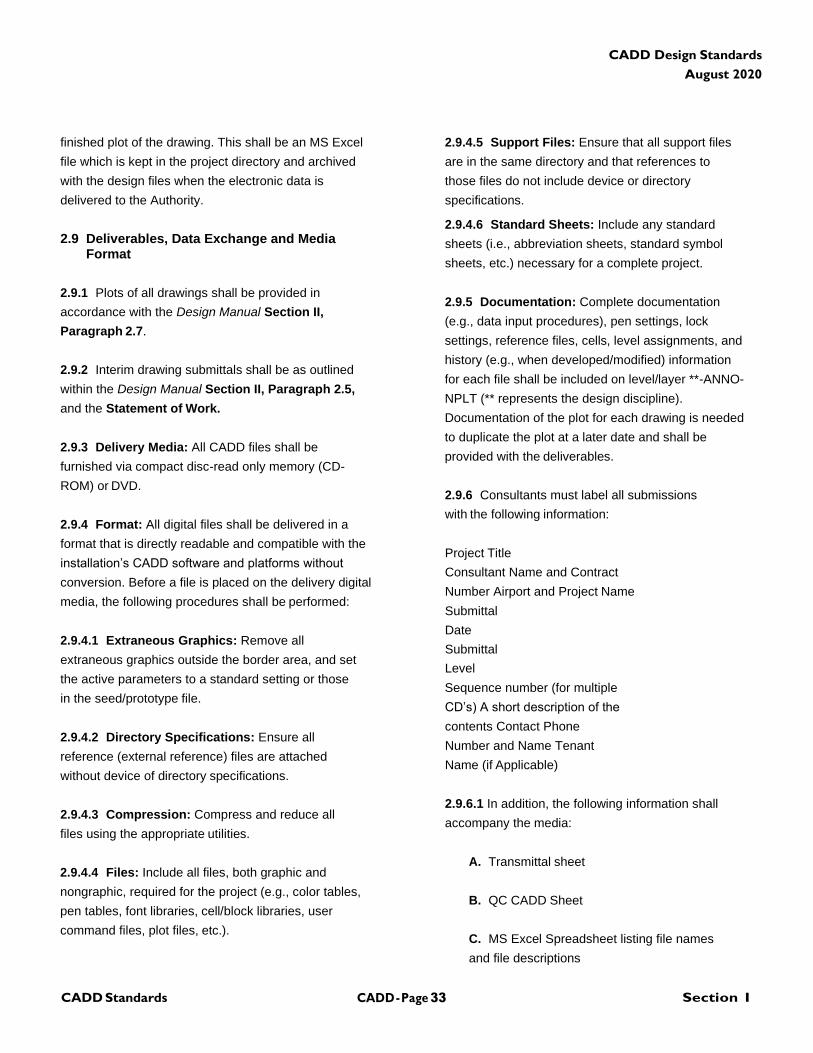
finished plot of the drawing. This shall be an MS Excel
file which is kept in the project directory and archived
with the design files when the electronic data is
delivered to the Authority.
2.9 Deliverables, Data Exchange and Media
Format
2.9.1 Plots of all drawings shall be provided in
accordance with the Design Manual Section II,
Paragraph 2.7.
2.9.2 Interim drawing submittals shall be as outlined
within the Design Manual Section II, Paragraph 2.5,
and the Statement of Work.
2.9.3 Delivery Media: All CADD files shall be
furnished via compact disc-read only memory (CD-
ROM) or DVD.
2.9.4 Format: All digital files shall be delivered in a
format that is directly readable and compatible with the
installation’s CADD software and platforms without
conversion. Before a file is placed on the delivery digital
media, the following procedures shall be performed:
2.9.4.1 Extraneous Graphics: Remove all
extraneous graphics outside the border area, and set
the active parameters to a standard setting or those
in the seed/prototype file.
2.9.4.2 Directory Specifications: Ensure all
reference (external reference) files are attached
without device of directory specifications.
2.9.4.3 Compression: Compress and reduce all
files using the appropriate utilities.
2.9.4.4 Files: Include all files, both graphic and
nongraphic, required for the project (e.g., color tables,
pen tables, font libraries, cell/block libraries, user
command files, plot files, etc.).
2.9.4.5 Support Files: Ensure that all support files
are in the same directory and that references to
those files do not include device or directory
specifications.
2.9.4.6 Standard Sheets: Include any standard
sheets (i.e., abbreviation sheets, standard symbol
sheets, etc.) necessary for a complete project.
2.9.5 Documentation: Complete documentation
(e.g., data input procedures), pen settings, lock
settings, reference files, cells, level assignments, and
history (e.g., when developed/modified) information
for each file shall be included on level/layer **-ANNO-
NPLT (** represents the design discipline).
Documentation of the plot for each drawing is needed
to duplicate the plot at a later date and shall be
provided with the deliverables.
2.9.6 Consultants must label all submissions
with the following information:
Project Title
Consultant Name and Contract
Number Airport and Project Name
Submittal
Date
Submittal
Level
Sequence number (for multiple
CD’s) A short description of the
contents Contact Phone
Number and Name Tenant
Name (if Applicable)
2.9.6.1 In addition, the following information shall
accompany the media:
A. Transmittal sheet
B. QC CADD Sheet
C. MS Excel Spreadsheet listing file names
and file descriptions
CADD - Page 34 Section I CADD Standards
CADD Design Standards
August 2020
2.10 Submittal Requirements
2.10.1 General: Consultants shall submit drawings in
compliance with the Authority CADD Standard with
each required submittal. At 100% submittal level, all
CADD drawings shall be submitted to include model
files, sheet files, reference files and any other files
required by Paragraph 2.9.
CADD - Page 35 Section I CADD Standards
CADD Design Standards
August 2020
(This Page Blank)
CADD - Page 36 Section I CADD Standards
CADD Design Standards
August 2020
CHAPTER 3 Drawing File Information
3.1 Naming Conventions
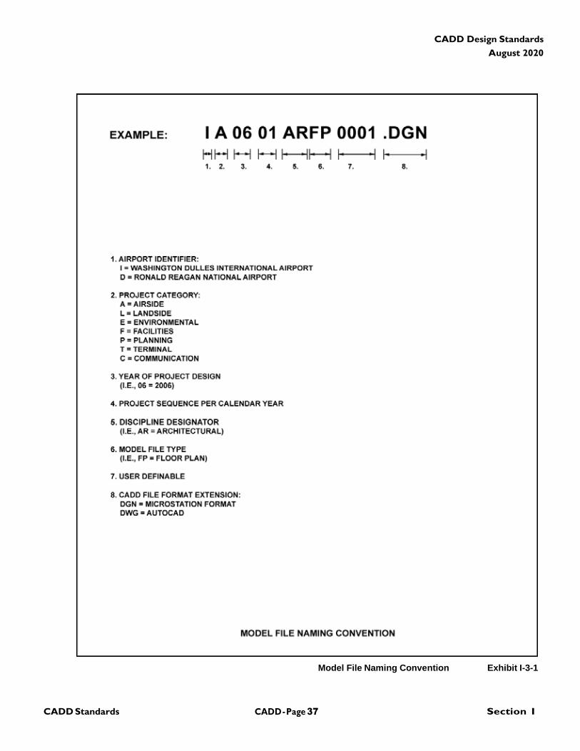
3.1.1 Model File Naming: Model files shall be named in
accordance with the naming convention outlined in the
applicable chapter exhibits.
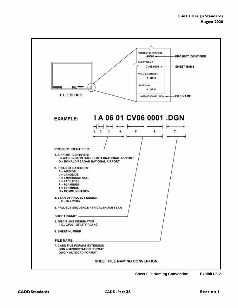
3.1.2 Sheet File Naming: Sheet files shall be named in
accordance with the naming convention outlined in chapter
exhibits. In assigning a sheet number, the sheet number
shall coordinate with the same name assigned to the
electronic sheet file.
3.2 Standard Sheet Formats (Cover Sheet and Title
Block Sheet)
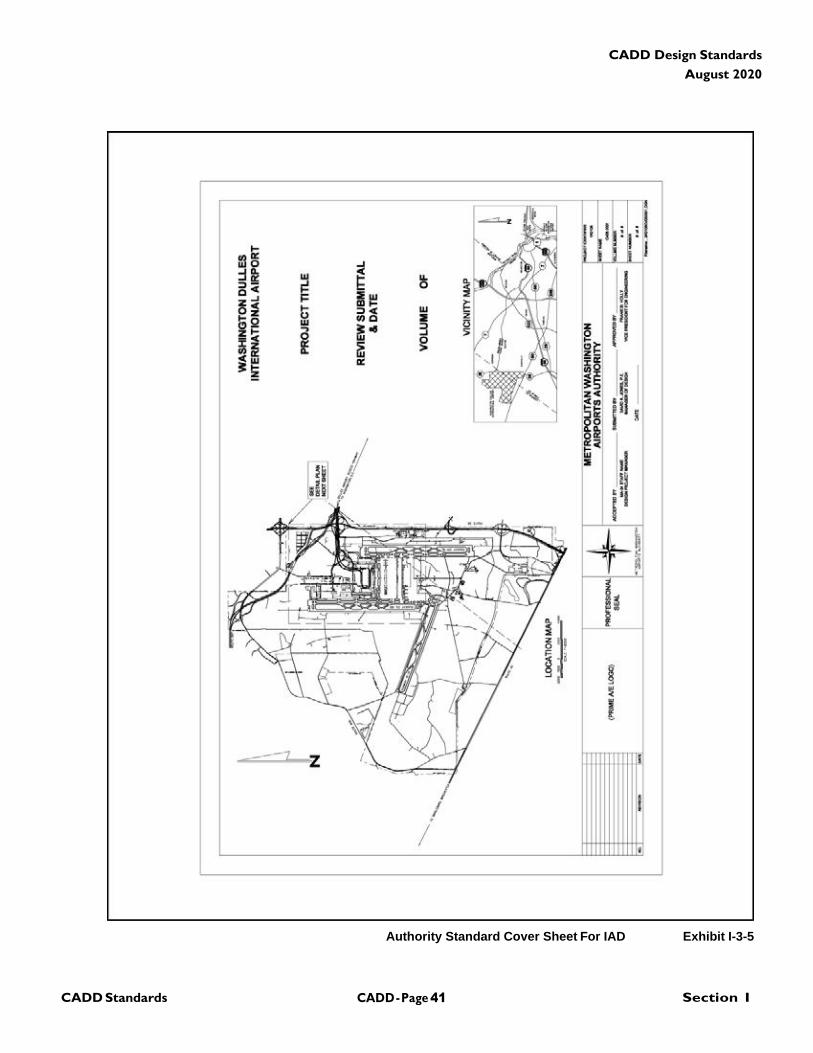
3.2.1 General: The standard format of Cover Sheets and
Title Block Sheets are shown in the applicable chapter
exhibits. The Authority will provide files of the cover
sheets and title block sheets in native electronic format for
Bentley MicroStation and AutoDesk AutoCAD.
3.3 Drawing Preparation/Arrangement
3.3.1 General: The title block sheets and cover sheets
shall be referenced into the CADD file. They shall not be
placed as a separate cell or block. The use of reference
files in the file set-up is required to ensure file integrity. The
use of reference files eliminates the need for duplication of
data reducing the problems encountered when updating
drawings. Sheet drawings shall be arranged in sequence as
defined in Table I-3-1.
3.3.2 Reference Files: In order to avoid conflicting
attachments of reference files, there shall be no duplicate
file names within the project directory structure or copies of
the same file within the project directory structure.
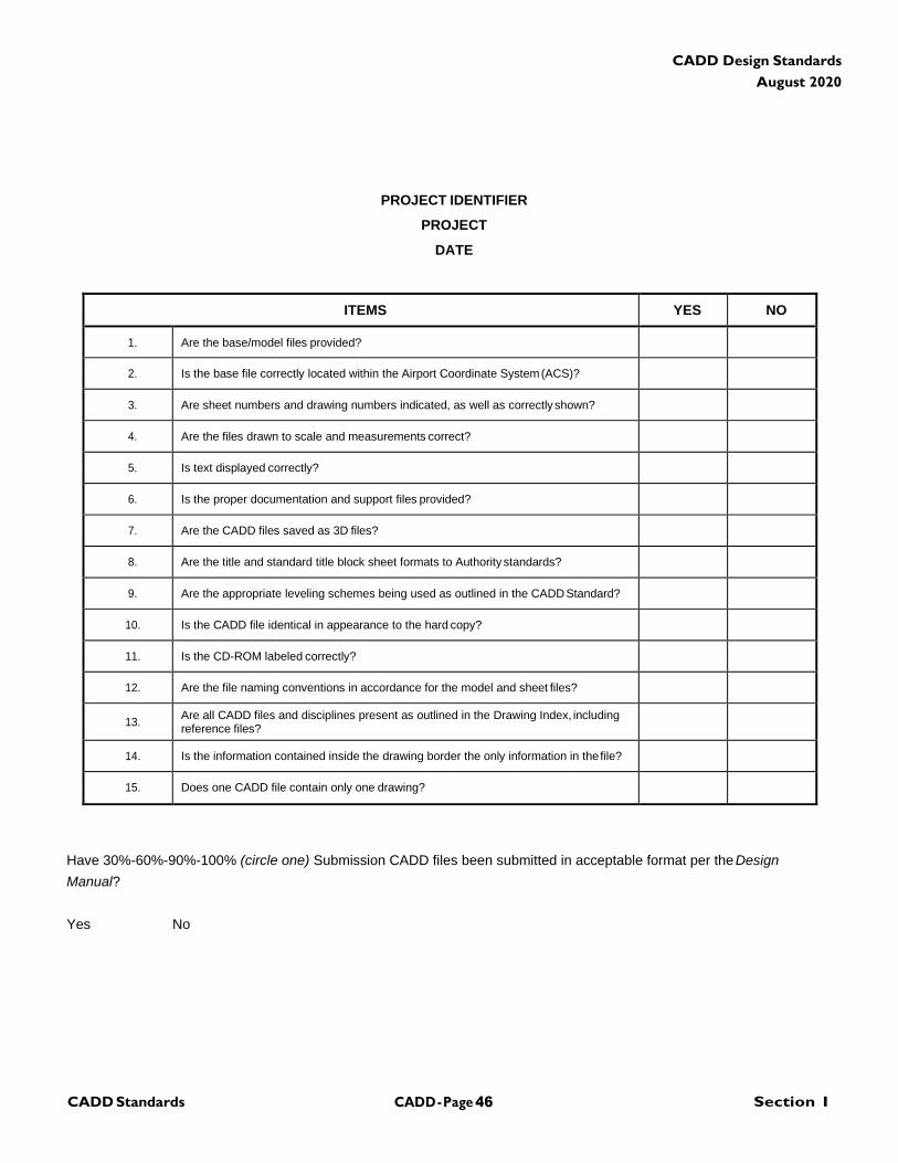
3.4 Quality Check (QC) CADD Checklist
3.4.1 General: The QC CADD checklist is shown on page
46. This checklist is used as a means of validating the
CADD files submitted have been quality inspected. An “X”
in the appropriate YES or NO field, with a signature,
indicates this item is in conformance with the items outlined
in the Design Manual Appendix 3 CADD Standards. This
QC CADD checklist shall be accompanied with each
submittal and may be submitted as a hard copy or
electronic file. The QC CADD Checklist is available on the
CD-ROM located in the CAD directory.
3.5 Addenda Sketches
3.5.1 Sketch Format: The standard format of 8 ½" x 11"
or 11" x 17" sketches are shown in chapter exhibits. The
Authority will provide files of the sketch formats in native
electronic format for Bentley MicroStation and AutoDesk
AutoCAD. It is the obligation of each designer to ensure
that all submittals match the hard-copy line work and
graphics exactly as shown. Any deviation will be rejected.
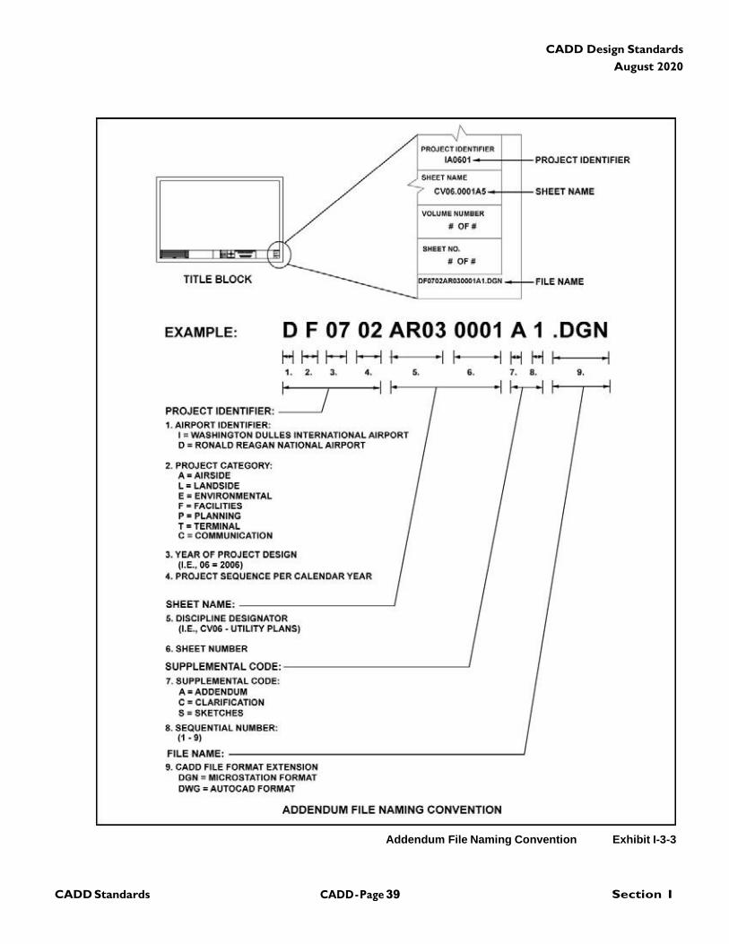
3.5.2 File Naming Conventions for Addenda or
Sketches: Model files and all drawing sheet files shall be
named in accordance with the Name designation
convention outlined in the applicable chapter exhibits. In
assigning a sheet number, the sheet number shall
coordinate with the same name assigned to the electronic
sheet file.
CADD - Page 37 Section I CADD Standards
CADD Design Standards
August 2020
Model File Naming Convention Exhibit I-3-1
CADD - Page 38 Section I CADD Standards
CADD Design Standards
August 2020
Sheet File Naming Convention Exhibit I-3-2
CADD - Page 39 Section I CADD Standards
CADD Design Standards
August 2020
Addendum File Naming Convention Exhibit I-3-3

CADD - Page 40 Section I CADD Standards
CADD Design Standards
August 2020
Authority Standard Drawing Sheet Titleblock For IAD Exhibit I-3-4
CADD - Page 41 Section I CADD Standards
CADD Design Standards
August 2020
Authority Standard Cover Sheet For IAD Exhibit I-3-5
CADD - Page 42 Section I CADD Standards
CADD Design Standards
August 2020
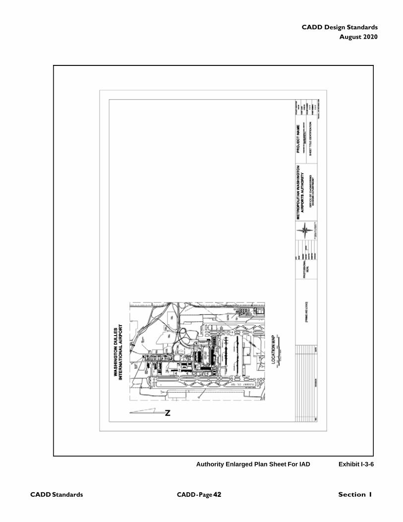
Authority Enlarged Plan Sheet For IAD Exhibit I-3-6
CADD - Page 43 Section I CADD Standards
CADD Design Standards
August 2020
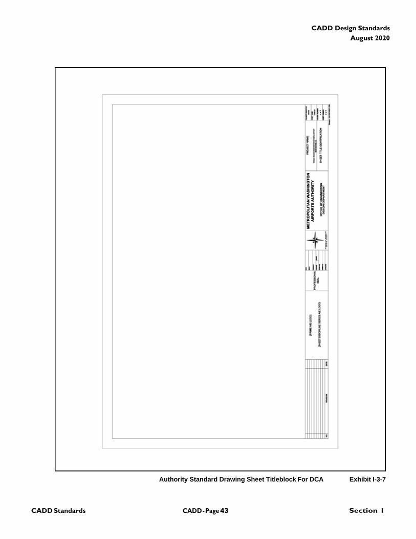
Authority Standard Drawing Sheet Titleblock For DCA Exhibit I-3-7
CADD - Page 44 Section I CADD Standards
CADD Design Standards
August 2020
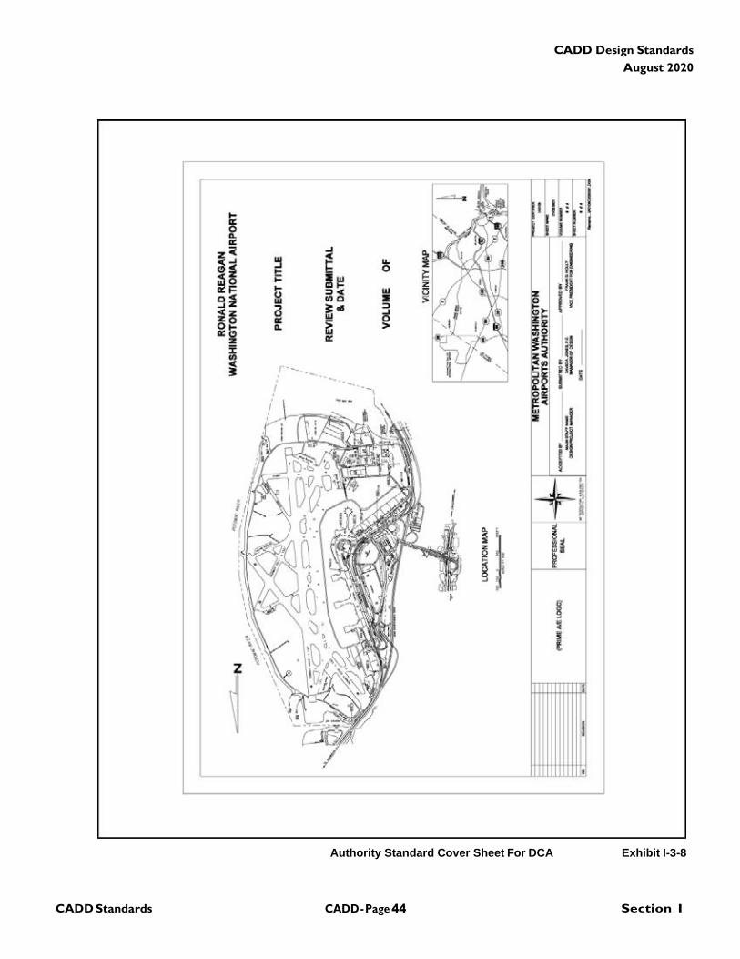
Authority Standard Cover Sheet For DCA Exhibit I-3-8
CADD - Page 45 Section I CADD Standards
CADD Design Standards
August 2020
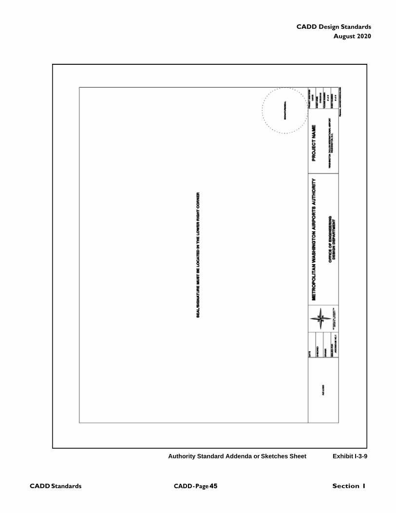
Authority Standard Addenda or Sketches Sheet Exhibit I-3-9
CADD - Page 46 Section I CADD Standards
CADD Design Standards
August 2020
PROJECT IDENTIFIER
PROJECT
DATE
ITEMS YES NO
1. Are the base/model files provided?
2. Is the base file correctly located within the Airport Coordinate System (ACS)?
3. Are sheet numbers and drawing numbers indicated, as well as correctly shown?
4. Are the files drawn to scale and measurements correct?
5. Is text displayed correctly?
6. Is the proper documentation and support files provided?
7. Are the CADD files saved as 3D files?
8. Are the title and standard title block sheet formats to Authority standards?
9. Are the appropriate leveling schemes being used as outlined in the CADD Standard?
10. Is the CADD file identical in appearance to the hard copy?
11. Is the CD-ROM labeled correctly?
12. Are the file naming conventions in accordance for the model and sheet files?
13. Are all CADD files and disciplines present as outlined in the Drawing Index, including reference files?
14. Is the information contained inside the drawing border the only information in the file?
15. Does one CADD file contain only one drawing?
Have 30%-60%-90%-100% (circle one) Submission CADD files been submitted in acceptable format per the Design
Manual?
Yes No
CADD - Page 47 Section I CADD Standards
CADD Design Standards
August 2020
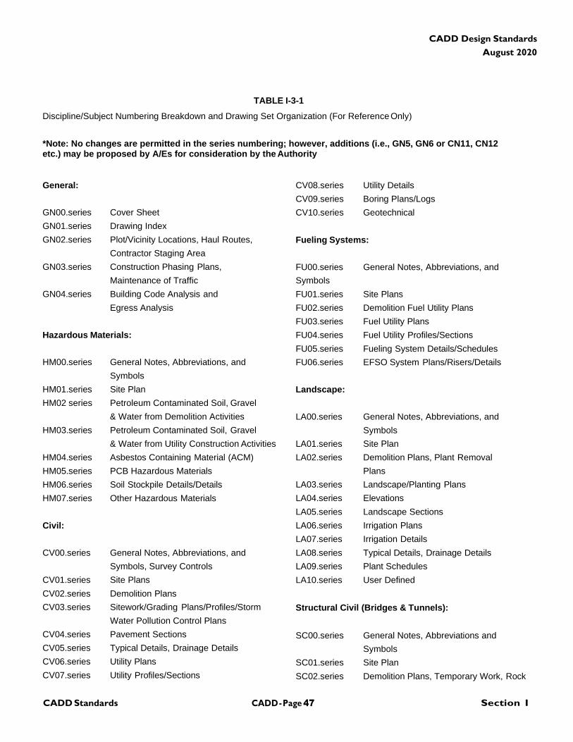
TABLE I-3-1
Discipline/Subject Numbering Breakdown and Drawing Set Organization (For Reference Only)
*Note: No changes are permitted in the series numbering; however, additions (i.e., GN5, GN6 or CN11, CN12 etc.) may be proposed by A/Es for consideration by the Authority
General:
GN00.series Cover Sheet
GN01.series Drawing Index
GN02.series Plot/Vicinity Locations, Haul Routes,
Contractor Staging Area
GN03.series Construction Phasing Plans,
Maintenance of Traffic
GN04.series Building Code Analysis and
Egress Analysis
Hazardous Materials:
HM00.series General Notes, Abbreviations, and
Symbols
HM01.series Site Plan
HM02 series Petroleum Contaminated Soil, Gravel
& Water from Demolition Activities
HM03.series Petroleum Contaminated Soil, Gravel
& Water from Utility Construction Activities
HM04.series Asbestos Containing Material (ACM)
HM05.series PCB Hazardous Materials
HM06.series Soil Stockpile Details/Details
HM07.series Other Hazardous Materials
Civil:
CV00.series General Notes, Abbreviations, and
Symbols, Survey Controls
CV01.series Site Plans
CV02.series Demolition Plans
CV03.series Sitework/Grading Plans/Profiles/Storm
Water Pollution Control Plans
CV04.series Pavement Sections
CV05.series Typical Details, Drainage Details
CV06.series Utility Plans
CV07.series Utility Profiles/Sections
CV08.series Utility Details
CV09.series Boring Plans/Logs
CV10.series Geotechnical
Fueling Systems:
FU00.series General Notes, Abbreviations, and
Symbols
FU01.series Site Plans
FU02.series Demolition Fuel Utility Plans
FU03.series Fuel Utility Plans
FU04.series Fuel Utility Profiles/Sections
FU05.series Fueling System Details/Schedules
FU06.series EFSO System Plans/Risers/Details
Landscape:
LA00.series General Notes, Abbreviations, and
Symbols
LA01.series Site Plan
LA02.series Demolition Plans, Plant Removal
Plans
LA03.series Landscape/Planting Plans
LA04.series Elevations
LA05.series Landscape Sections
LA06.series Irrigation Plans
LA07.series Irrigation Details
LA08.series Typical Details, Drainage Details
LA09.series Plant Schedules
LA10.series User Defined
Structural Civil (Bridges & Tunnels):
SC00.series General Notes, Abbreviations and
Symbols
SC01.series Site Plan
SC02.series Demolition Plans, Temporary Work, Rock
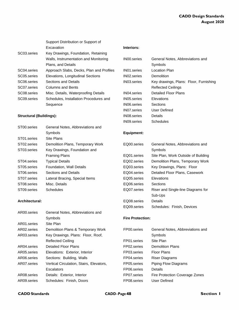
CADD - Page 48 Section I CADD Standards
CADD Design Standards
August 2020
Support Distribution or Support of
Excavation
SC03.series Key Drawings, Foundation, Retaining
Walls, Instrumentation and Monitoring
Plans, and Details
SC04.series Approach Slabs, Decks, Plan and Profiles
SC05.series Elevations, Longitudinal Sections
SC06.series Sections and Details
SC07.series Columns and Bents
SC08.series Misc. Details, Waterproofing Details
SC09.series Schedules, Installation Procedures and
Sequence
Structural (Buildings):
ST00.series General Notes, Abbreviations and
Symbols
ST01.series Site Plans
ST02.series Demolition Plans, Temporary Work
ST03.series Key Drawings, Foundation and
Framing Plans
ST04.series Typical Details
ST05.series Foundation, Wall Details
ST06.series Sections and Details
ST07.series Lateral Bracing, Special Items
ST08.series Misc. Details
ST09.series Schedules
Architectural:
AR00.series General Notes, Abbreviations and
Symbols
AR01.series Site Plan
AR02.series Demolition Plans & Temporary Work
AR03.series Key Drawings. Plans: Floor, Roof,
Reflected Ceiling
AR04.series Detailed Floor Plans
AR05.series Elevations: Exterior, Interior
AR06.series Sections: Building, Walls
AR07.series Vertical Circulation, Stairs, Elevators,
Escalators
AR08.series Details: Exterior, Interior
AR09.series Schedules: Finish, Doors
Interiors:
IN00.series General Notes, Abbreviations and
Symbols
IN01.series Location Plan
IN02.series Demolition
IN03.series Key drawings, Plans: Floor, Furnishing
Reflected Ceilings
IN04.series Detailed Floor Plans
IN05.series Elevations
IN06.series Sections
IN07.series User Defined
IN08.series Details
IN09.series Schedules
Equipment:
EQ00.series General Notes, Abbreviations and
Symbols
EQ01.series Site Plan, Work Outside of Building
EQ02.series Demolition Plans, Temporary Work
EQ03.series Key Drawings, Plans: Floor
EQ04.series Detailed Floor Plans, Casework
EQ05.series Elevations
EQ06.series Sections
EQ07.series Riser and Single-line Diagrams for
Sub-Ups
EQ08.series Details
EQ09.series Schedules: Finish, Devices
Fire Protection:
FP00.series General Notes, Abbreviations and
Symbols
FP01.series Site Plan
FP02.series Demolition Plans
FP03.series Floor Plans
FP04.series Riser Diagrams
FP05.series Piping Flow Diagrams
FP06.series Details
FP07.series Fire Protection Coverage Zones
FP08.series User Defined
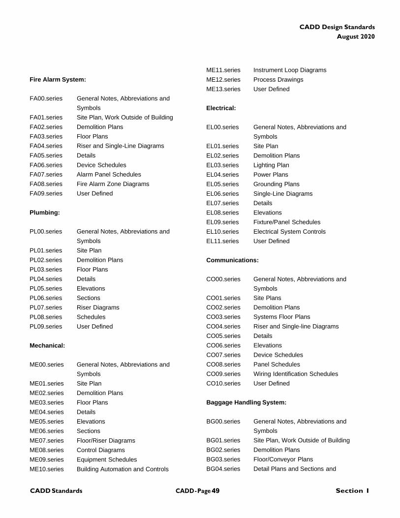
CADD - Page 49 Section I CADD Standards
CADD Design Standards
August 2020
Fire Alarm System:
FA00.series General Notes, Abbreviations and
Symbols
FA01.series Site Plan, Work Outside of Building
FA02.series Demolition Plans
FA03.series Floor Plans
FA04.series Riser and Single-Line Diagrams
FA05.series Details
FA06.series Device Schedules
FA07.series Alarm Panel Schedules
FA08.series Fire Alarm Zone Diagrams
FA09.series User Defined
Plumbing:
PL00.series General Notes, Abbreviations and
Symbols
PL01.series Site Plan
PL02.series Demolition Plans
PL03.series Floor Plans
PL04.series Details
PL05.series Elevations
PL06.series Sections
PL07.series Riser Diagrams
PL08.series Schedules
PL09.series User Defined
Mechanical:
ME00.series General Notes, Abbreviations and
Symbols
ME01.series Site Plan
ME02.series Demolition Plans
ME03.series Floor Plans
ME04.series Details
ME05.series Elevations
ME06.series Sections
ME07.series Floor/Riser Diagrams
ME08.series Control Diagrams
ME09.series Equipment Schedules
ME10.series Building Automation and Controls
ME11.series Instrument Loop Diagrams
ME12.series Process Drawings
ME13.series User Defined
Electrical:
EL00.series General Notes, Abbreviations and
Symbols
EL01.series Site Plan
EL02.series Demolition Plans
EL03.series Lighting Plan
EL04.series Power Plans
EL05.series Grounding Plans
EL06.series Single-Line Diagrams
EL07.series Details
EL08.series Elevations
EL09.series Fixture/Panel Schedules
EL10.series Electrical System Controls
EL11.series User Defined
Communications:
CO00.series General Notes, Abbreviations and
Symbols
CO01.series Site Plans
CO02.series Demolition Plans
CO03.series Systems Floor Plans
CO04.series Riser and Single-line Diagrams
CO05.series Details
CO06.series Elevations
CO07.series Device Schedules
CO08.series Panel Schedules
CO09.series Wiring Identification Schedules
CO10.series User Defined
Baggage Handling System:
BG00.series General Notes, Abbreviations and
Symbols
BG01.series Site Plan, Work Outside of Building
BG02.series Demolition Plans
BG03.series Floor/Conveyor Plans
BG04.series Detail Plans and Sections and
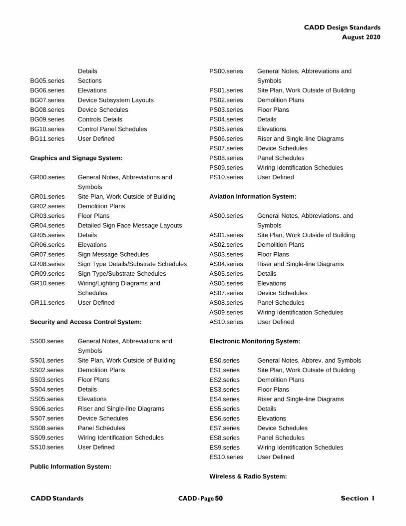
CADD - Page 50 Section I CADD Standards
CADD Design Standards
August 2020
Details
BG05.series Sections
BG06.series Elevations
BG07.series Device Subsystem Layouts
BG08.series Device Schedules
BG09.series Controls Details
BG10.series Control Panel Schedules
BG11.series User Defined
Graphics and Signage System:
GR00.series General Notes, Abbreviations and
Symbols
GR01.series Site Plan, Work Outside of Building
GR02.series Demolition Plans
GR03.series Floor Plans
GR04.series Detailed Sign Face Message Layouts
GR05.series Details
GR06.series Elevations
GR07.series Sign Message Schedules
GR08.series Sign Type Details/Substrate Schedules
GR09.series Sign Type/Substrate Schedules
GR10.series Wiring/Lighting Diagrams and
Schedules
GR11.series User Defined
Security and Access Control System:
SS00.series General Notes, Abbreviations and
Symbols
SS01.series Site Plan, Work Outside of Building
SS02.series Demolition Plans
SS03.series Floor Plans
SS04.series Details
SS05.series Elevations
SS06.series Riser and Single-line Diagrams
SS07.series Device Schedules
SS08.series Panel Schedules
SS09.series Wiring Identification Schedules
SS10.series User Defined
Public Information System:
PS00.series General Notes, Abbreviations and
Symbols
PS01.series Site Plan, Work Outside of Building
PS02.series Demolition Plans
PS03.series Floor Plans
PS04.series Details
PS05.series Elevations
PS06.series Riser and Single-line Diagrams
PS07.series Device Schedules
PS08.series Panel Schedules
PS09.series Wiring Identification Schedules
PS10.series User Defined
Aviation Information System:
AS00.series General Notes, Abbreviations. and
Symbols
AS01.series Site Plan, Work Outside of Building
AS02.series Demolition Plans
AS03.series Floor Plans
AS04.series Riser and Single-line Diagrams
AS05.series Details
AS06.series Elevations
AS07.series Device Schedules
AS08.series Panel Schedules
AS09.series Wiring Identification Schedules
AS10.series User Defined
Electronic Monitoring System:
ES0.series General Notes, Abbrev. and Symbols
ES1.series Site Plan, Work Outside of Building
ES2.series Demolition Plans
ES3.series Floor Plans
ES4.series Riser and Single-line Diagrams
ES5.series Details
ES6.series Elevations
ES7.series Device Schedules
ES8.series Panel Schedules
ES9.series Wiring Identification Schedules
ES10.series User Defined
Wireless & Radio System:
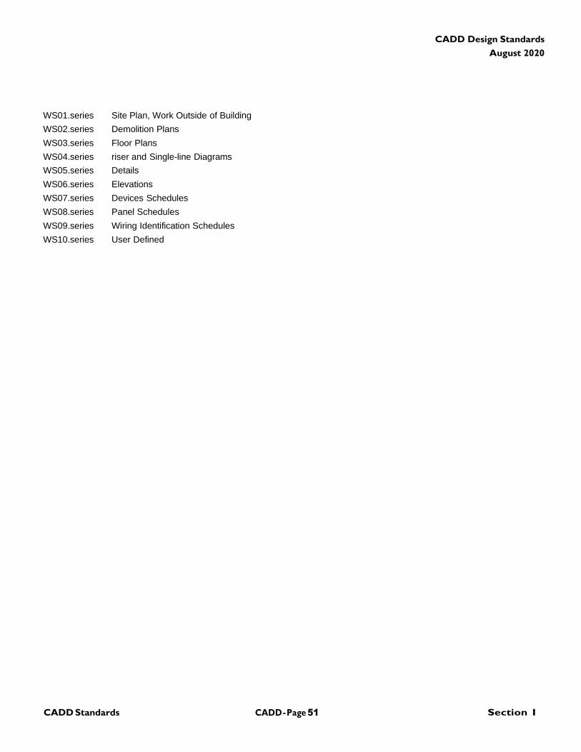
CADD - Page 51 Section I CADD Standards
CADD Design Standards
August 2020
WS01.series Site Plan, Work Outside of Building
WS02.series Demolition Plans
WS03.series Floor Plans
WS04.series riser and Single-line Diagrams
WS05.series Details
WS06.series Elevations
WS07.series Devices Schedules
WS08.series Panel Schedules
WS09.series Wiring Identification Schedules
WS10.series User Defined
CADD - Page 52 Section I CADD Standards
CADD Design Standards
August 2020
(This Page Blank)
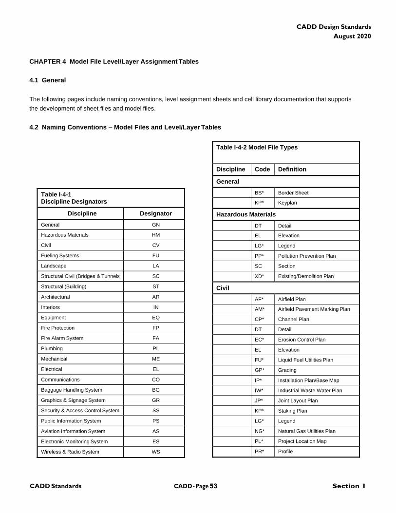
CADD - Page 53 Section I CADD Standards
CADD Design Standards
August 2020
CHAPTER 4 Model File Level/Layer Assignment Tables
4.1 General
The following pages include naming conventions, level assignment sheets and cell library documentation that supports
the development of sheet files and model files.
4.2 Naming Conventions – Model Files and Level/Layer Tables
Table I-4-1 Discipline Designators
Discipline Designator
General GN
Hazardous Materials HM
Civil CV
Fueling Systems FU
Landscape LA
Structural Civil (Bridges & Tunnels SC
Structural (Building) ST
Architectural AR
Interiors IN
Equipment EQ
Fire Protection FP
Fire Alarm System FA
Plumbing PL
Mechanical ME
Electrical EL
Communications CO
Baggage Handling System BG
Graphics & Signage System GR
Security & Access Control System SS
Public Information System PS
Aviation Information System AS
Electronic Monitoring System ES
Wireless & Radio System WS
Table I-4-2 Model File Types
Discipline Code Definition
General
BS* Border Sheet
KP* Keyplan
Hazardous Materials
DT Detail
EL Elevation
LG* Legend
PP* Pollution Prevention Plan
SC Section
XD* Existing/Demolition Plan
Civil
AF* Airfield Plan
AM* Airfield Pavement Marking Plan
CP* Channel Plan
DT Detail
EC* Erosion Control Plan
EL Elevation
FU* Liquid Fuel Utilities Plan
GP* Grading
IP* Installation Plan/Base Map
IW* Industrial Waste Water Plan
JP* Joint Layout Plan
KP* Staking Plan
LG* Legend
NG* Natural Gas Utilities Plan
PL* Project Location Map
PR* Profile
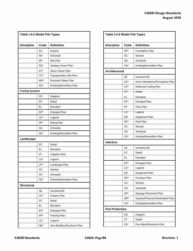
CADD - Page 54 Section I CADD Standards
CADD Design Standards
August 2020
Table I-4-2 Model File Types Table I-4-2 Model File Types
Discipline Code Definition Discipline Code Definition
SC Section NP* Foundation Plan
SH Schedule SC Section
SP Site Plan SH Schedule
SS* Sanitary Sewer Plan XD* Existing/Demolition Plan
ST* Storm Sewer Plan Architectural
TS* Transportation Site Plan 3D Isometric/3D
WA* Domestic Water Plan AC* Area Calculations/Occupancy Plan
XD* Existing/Demolition Plan CP* Reflected Ceiling Plan
Fueling Systems DT Detail
DG Diagram EL Elevation
DT Detail EP* Enlarged Plan
EL Elevation FP Floor Plan
EP* Enlarged Plan LG* Legend
LG* Legend QP Equipment Plan
RP* Roof Plan PP* Piping Plan
SC Section SH Schedule
SH Schedule XD* Existing/Demolition Plan
XD* Existing/Demolition Plan Landscape
Interiors DT Detail
3D Isometric/3D EL Elevation
DT Detail IP* Irrigation Plan
EL Elevation LG* Legend
EP* Enlarged Plan LP* Landscape Plan
LG* Legend SC Section
QP Equipment Plan SH Schedule
RP* Furniture Plan XD* Existing/Demolition Plan
SC Section Structural
SH Schedule 3D Isometric/3D
SP* Signage Placement Plan CP* Column Plan
WP* System/Prewired Workstation Plan DT Detail
XD* Existing/Demolition Plan EL Elevation
Fire Protection EP* Enlarged Plan
DG Diagram FP* Framing Plan
DT Detail LG* Legend
FA* Fire Alarm/Detection Plan NB* Non-Building Structures Plan
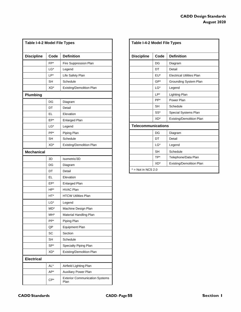
CADD - Page 55 Section I CADD Standards
CADD Design Standards
August 2020
Table I-4-2 Model File Types Table I-4-2 Model File Types
Discipline Code Definition Discipline Code Definition
FP* Fire Suppression Plan DG Diagram
LG* Legend DT Detail
LP* Life Safety Plan EU* Electrical Utilities Plan
SH Schedule GP* Grounding System Plan
XD* Existing/Demolition Plan LG* Legend
Plumbing LP* Lighting Plan
PP* Power Plan DG Diagram
SH Schedule DT Detail
SS* Special Systems Plan EL Elevation
XD* Existing/Demolition Plan EP* Enlarged Plan
Telecommunications LG* Legend
PP* Piping Plan DG Diagram
SH Schedule DT Detail
XD* Existing/Demolition Plan LG* Legend
Mechanical SH Schedule
TP* Telephone/Data Plan 3D Isometric/3D
XD* Existing/Demolition Plan DG Diagram
* = Not in NCS 2.0 DT Detail
EL Elevation
EP* Enlarged Plan
HP* HVAC Plan
HT* HTCW Utilities Plan
LG* Legend
MD* Machine Design Plan
MH* Material Handling Plan
PP* Piping Plan
QP Equipment Plan
SC Section
SH Schedule
SP* Specialty Piping Plan
XD* Existing/Demolition Plan
Electrical
AL* Airfield Lighting Plan
AP* Auxiliary Power Plan
CP* Exterior Communication Systems Plan
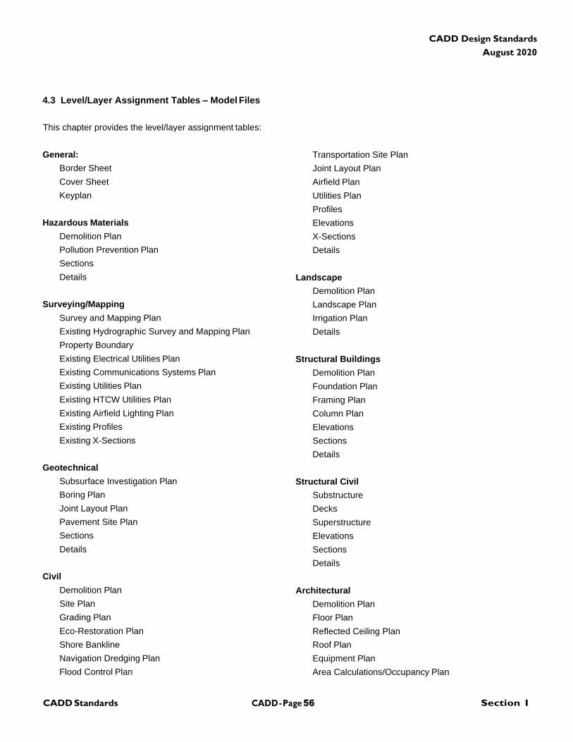
CADD - Page 56 Section I CADD Standards
CADD Design Standards
August 2020
4.3 Level/Layer Assignment Tables – Model Files
This chapter provides the level/layer assignment tables:
General:
Border Sheet
Cover Sheet
Keyplan
Hazardous Materials
Demolition Plan
Pollution Prevention Plan
Sections
Details
Surveying/Mapping
Survey and Mapping Plan
Existing Hydrographic Survey and Mapping Plan
Property Boundary
Existing Electrical Utilities Plan
Existing Communications Systems Plan
Existing Utilities Plan
Existing HTCW Utilities Plan
Existing Airfield Lighting Plan
Existing Profiles
Existing X-Sections
Geotechnical
Subsurface Investigation Plan
Boring Plan
Joint Layout Plan
Pavement Site Plan
Sections
Details
Civil
Demolition Plan
Site Plan
Grading Plan
Eco-Restoration Plan
Shore Bankline
Navigation Dredging Plan
Flood Control Plan
Transportation Site Plan
Joint Layout Plan
Airfield Plan
Utilities Plan
Profiles
Elevations
X-Sections
Details
Landscape
Demolition Plan
Landscape Plan
Irrigation Plan
Details
Structural Buildings
Demolition Plan
Foundation Plan
Framing Plan
Column Plan
Elevations
Sections
Details
Structural Civil
Substructure
Decks
Superstructure
Elevations
Sections
Details
Architectural
Demolition Plan
Floor Plan
Reflected Ceiling Plan
Roof Plan
Equipment Plan
Area Calculations/Occupancy Plan
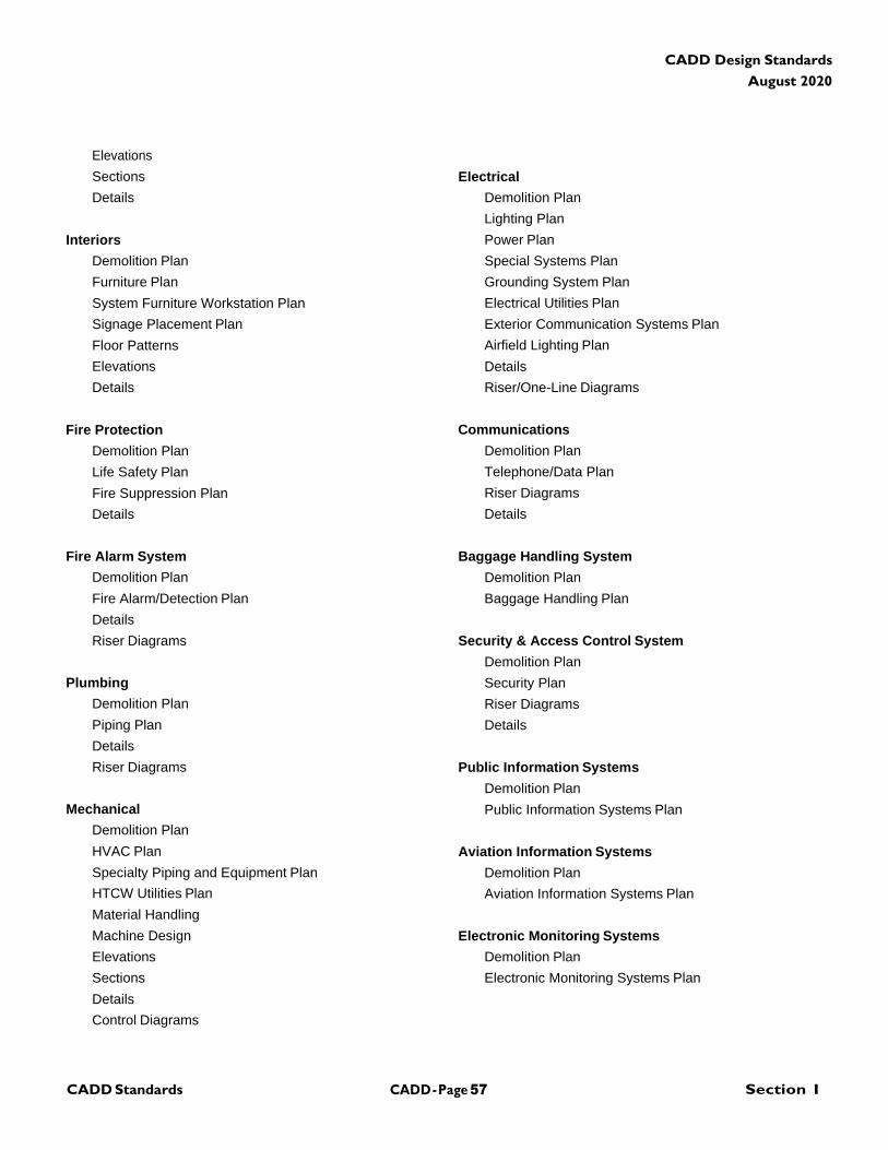
CADD - Page 57 Section I CADD Standards
CADD Design Standards
August 2020
Elevations
Sections
Details
Interiors
Demolition Plan
Furniture Plan
System Furniture Workstation Plan
Signage Placement Plan
Floor Patterns
Elevations
Details
Fire Protection
Demolition Plan
Life Safety Plan
Fire Suppression Plan
Details
Fire Alarm System
Demolition Plan
Fire Alarm/Detection Plan
Details
Riser Diagrams
Plumbing
Demolition Plan
Piping Plan
Details
Riser Diagrams
Mechanical
Demolition Plan
HVAC Plan
Specialty Piping and Equipment Plan
HTCW Utilities Plan
Material Handling
Machine Design
Elevations
Sections
Details
Control Diagrams
Electrical
Demolition Plan
Lighting Plan
Power Plan
Special Systems Plan
Grounding System Plan
Electrical Utilities Plan
Exterior Communication Systems Plan
Airfield Lighting Plan
Details
Riser/One-Line Diagrams
Communications
Demolition Plan
Telephone/Data Plan
Riser Diagrams
Details
Baggage Handling System
Demolition Plan
Baggage Handling Plan
Security & Access Control System
Demolition Plan
Security Plan
Riser Diagrams
Details
Public Information Systems
Demolition Plan
Public Information Systems Plan
Aviation Information Systems
Demolition Plan
Aviation Information Systems Plan
Electronic Monitoring Systems
Demolition Plan
Electronic Monitoring Systems Plan
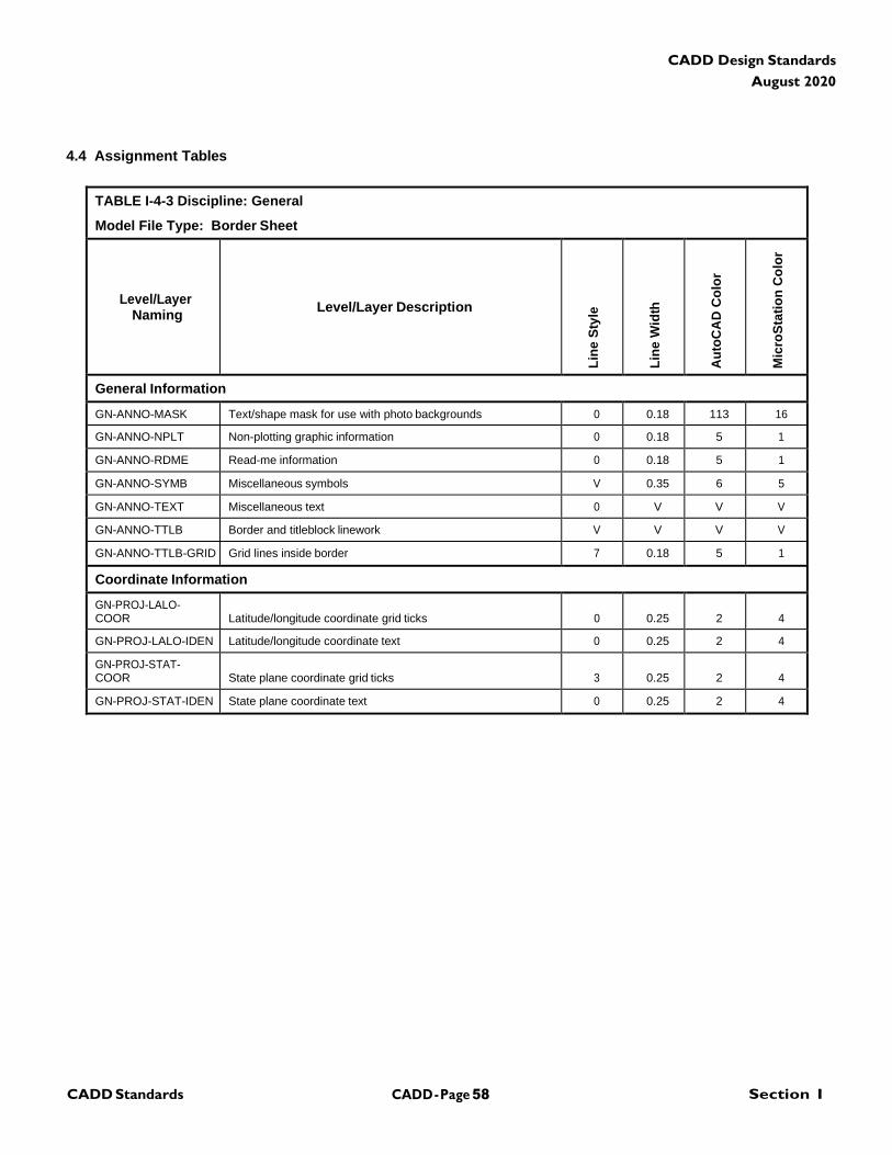
CADD - Page 58 Section I CADD Standards
CADD Design Standards
August 2020
4.4 Assignment Tables
TABLE I-4-3 Discipline: General
Model File Type: Border Sheet
Level/Layer
Naming
Level/Layer Description
Lin
e S
tyle
Lin
e W
idth
Au
toC
AD
Co
lor
Mic
roS
tati
on
Co
lor
General Information
GN-ANNO-MASK Text/shape mask for use with photo backgrounds 0 0.18 113 16
GN-ANNO-NPLT Non-plotting graphic information 0 0.18 5 1
GN-ANNO-RDME Read-me information 0 0.18 5 1
GN-ANNO-SYMB Miscellaneous symbols V 0.35 6 5
GN-ANNO-TEXT Miscellaneous text 0 V V V
GN-ANNO-TTLB Border and titleblock linework V V V V
GN-ANNO-TTLB-GRID Grid lines inside border 7 0.18 5 1
Coordinate Information
GN-PROJ-LALO- COOR
Latitude/longitude coordinate grid ticks
0
0.25
2
4
GN-PROJ-LALO-IDEN Latitude/longitude coordinate text 0 0.25 2 4
GN-PROJ-STAT- COOR
State plane coordinate grid ticks
3
0.25
2
4
GN-PROJ-STAT-IDEN State plane coordinate text 0 0.25 2 4
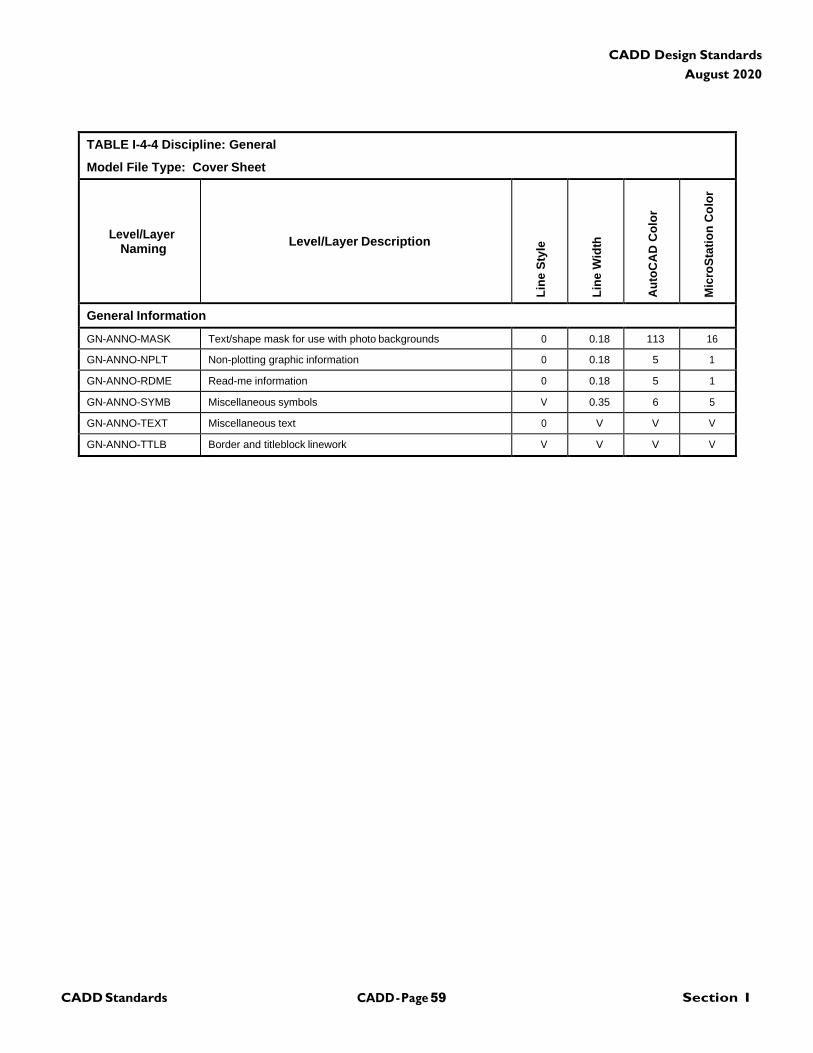
CADD - Page 59 Section I CADD Standards
CADD Design Standards
August 2020
TABLE I-4-4 Discipline: General
Model File Type: Cover Sheet
Level/Layer
Naming
Level/Layer Description
Lin
e S
tyle
Lin
e W
idth
Au
toC
AD
Co
lor
Mic
roS
tati
on
Co
lor
General Information
GN-ANNO-MASK Text/shape mask for use with photo backgrounds 0 0.18 113 16
GN-ANNO-NPLT Non-plotting graphic information 0 0.18 5 1
GN-ANNO-RDME Read-me information 0 0.18 5 1
GN-ANNO-SYMB Miscellaneous symbols V 0.35 6 5
GN-ANNO-TEXT Miscellaneous text 0 V V V
GN-ANNO-TTLB Border and titleblock linework V V V V
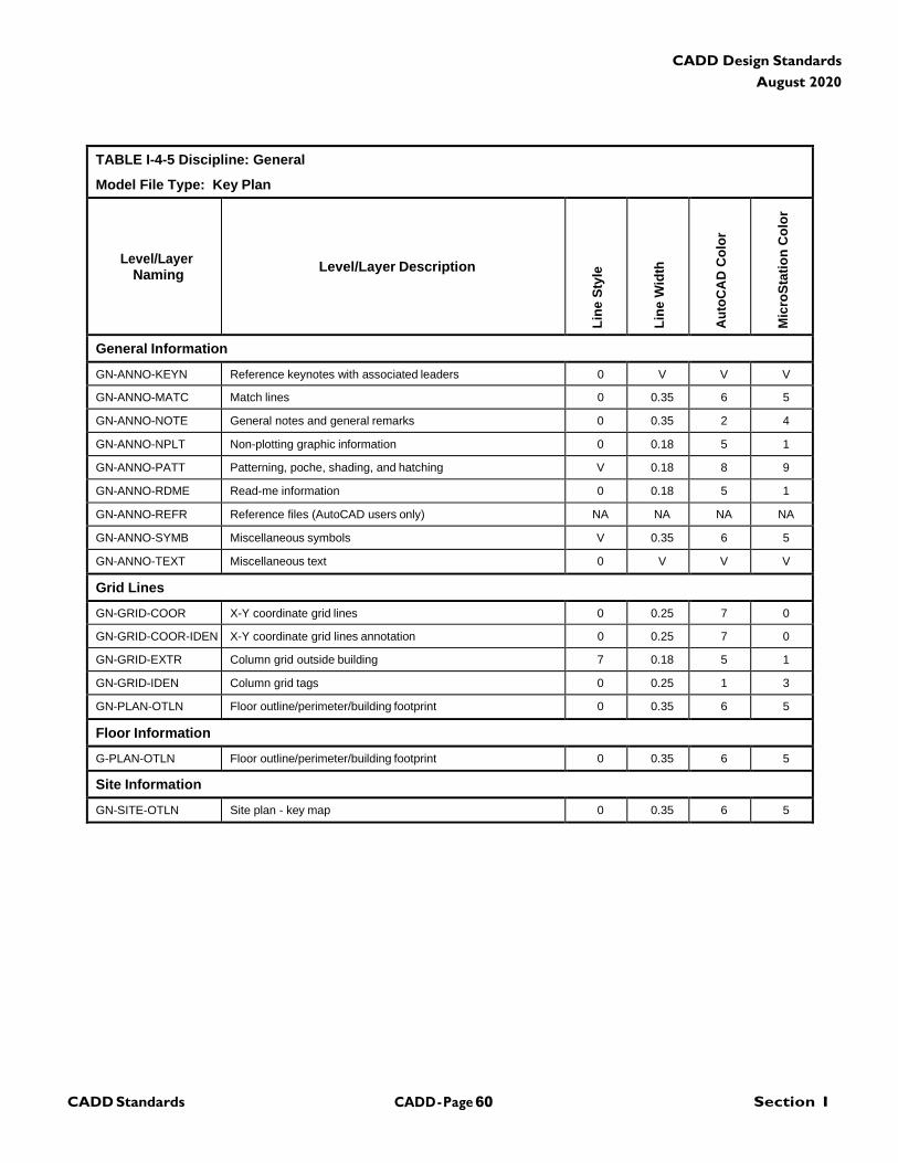
CADD - Page 60 Section I CADD Standards
CADD Design Standards
August 2020
TABLE I-4-5 Discipline: General
Model File Type: Key Plan
Level/Layer
Naming
Level/Layer Description
Lin
e S
tyle
Lin
e W
idth
Au
toC
AD
Co
lor
Mic
roS
tati
on
Co
lor
General Information
GN-ANNO-KEYN Reference keynotes with associated leaders 0 V V V
GN-ANNO-MATC Match lines 0 0.35 6 5
GN-ANNO-NOTE General notes and general remarks 0 0.35 2 4
GN-ANNO-NPLT Non-plotting graphic information 0 0.18 5 1
GN-ANNO-PATT Patterning, poche, shading, and hatching V 0.18 8 9
GN-ANNO-RDME Read-me information 0 0.18 5 1
GN-ANNO-REFR Reference files (AutoCAD users only) NA NA NA NA
GN-ANNO-SYMB Miscellaneous symbols V 0.35 6 5
GN-ANNO-TEXT Miscellaneous text 0 V V V
Grid Lines
GN-GRID-COOR X-Y coordinate grid lines 0 0.25 7 0
GN-GRID-COOR-IDEN X-Y coordinate grid lines annotation 0 0.25 7 0
GN-GRID-EXTR Column grid outside building 7 0.18 5 1
GN-GRID-IDEN Column grid tags 0 0.25 1 3
GN-PLAN-OTLN Floor outline/perimeter/building footprint 0 0.35 6 5
Floor Information
G-PLAN-OTLN Floor outline/perimeter/building footprint 0 0.35 6 5
Site Information
GN-SITE-OTLN Site plan - key map 0 0.35 6 5
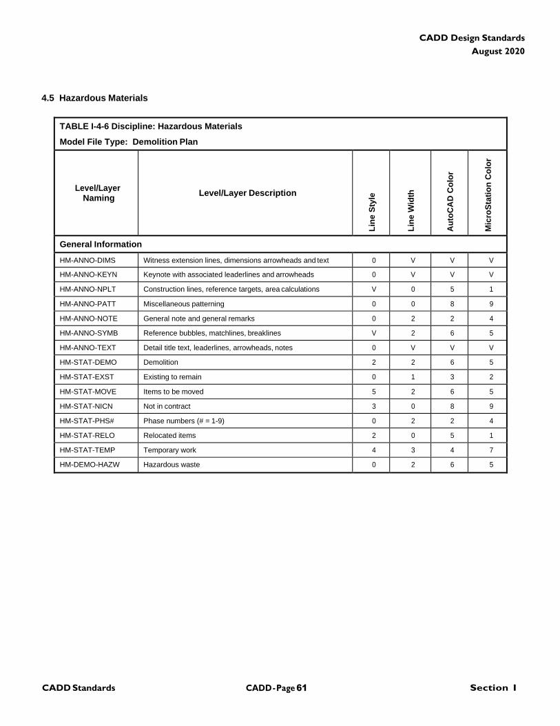
CADD - Page 61 Section I CADD Standards
CADD Design Standards
August 2020
4.5 Hazardous Materials
TABLE I-4-6 Discipline: Hazardous Materials
Model File Type: Demolition Plan
Level/Layer
Naming
Level/Layer Description
Lin
e S
tyle
Lin
e W
idth
Au
toC
AD
Co
lor
Mic
roS
tati
on
Co
lor
General Information
HM-ANNO-DIMS Witness extension lines, dimensions arrowheads and text 0 V V V
HM-ANNO-KEYN Keynote with associated leaderlines and arrowheads 0 V V V
HM-ANNO-NPLT Construction lines, reference targets, area calculations V 0 5 1
HM-ANNO-PATT Miscellaneous patterning 0 0 8 9
HM-ANNO-NOTE General note and general remarks 0 2 2 4
HM-ANNO-SYMB Reference bubbles, matchlines, breaklines V 2 6 5
HM-ANNO-TEXT Detail title text, leaderlines, arrowheads, notes 0 V V V
HM-STAT-DEMO Demolition 2 2 6 5
HM-STAT-EXST Existing to remain 0 1 3 2
HM-STAT-MOVE Items to be moved 5 2 6 5
HM-STAT-NICN Not in contract 3 0 8 9
HM-STAT-PHS# Phase numbers (# = 1-9) 0 2 2 4
HM-STAT-RELO Relocated items 2 0 5 1
HM-STAT-TEMP Temporary work 4 3 4 7
HM-DEMO-HAZW Hazardous waste 0 2 6 5
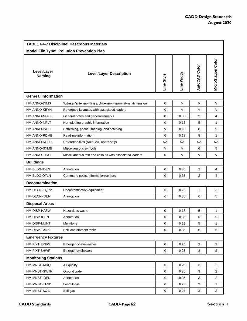
CADD - Page 62 Section I CADD Standards
CADD Design Standards
August 2020
TABLE I-4-7 Discipline: Hazardous Materials
Model File Type: Pollution Prevention Plan
Level/Layer
Naming
Level/Layer Description
Lin
e S
tyle
Lin
e W
idth
Au
toC
AD
Co
lor
Mic
roS
tati
on
Co
lor
General Information
HM-ANNO-DIMS Witness/extension lines, dimension terminators, dimension 0 V V V
HM-ANNO-KEYN Reference keynotes with associated leaders 0 V V V
HM-ANNO-NOTE General notes and general remarks 0 0.35 2 4
HM-ANNO-NPLT Non-plotting graphic information 0 0.18 5 1
HM-ANNO-PATT Patterning, poche, shading, and hatching V 0.18 8 9
HM-ANNO-RDME Read-me information 0 0.18 5 1
HM-ANNO-REFR Reference files (AutoCAD users only) NA NA NA NA
HM-ANNO-SYMB Miscellaneous symbols V V 6 5
HM-ANNO-TEXT Miscellaneous text and callouts with associated leaders 0 V V V
Buildings
HM-BLDG-IDEN Annotation 0 0.35 2 4
HM-BLDG-OTLN Command posts, information centers 0 0.35 2 4
Decontamination
HM-DECN-EQPM Decontamination equipment 0 0.25 1 3
HM-DECN-IDEN Annotation 0 0.35 6 5
Disposal Areas
HM-DISP-HAZW Hazardous waste 0 0.18 5 1
HM-DISP-IDEN Annotation 0 0.35 6 5
HM-DISP-MUNT Munitions 0 0.18 5 1
HM-DISP-TANK Spill containment tanks 0 0.35 6 5
Emergency Fixtures
HM-FIXT-EYEW Emergency eyewashes 0 0.25 3 2
HM-FIXT-SHWR Emergency showers 0 0.25 3 2
Monitoring Stations
HM-MNST-AIRQ Air quality 0 0.25 3 2
HM-MNST-GWTR Ground water 0 0.25 3 2
HM-MNST-IDEN Annotation 0 0.25 3 2
HM-MNST-LAND Landfill gas 0 0.25 3 2
HM-MNST-SOIL Soil gas 0 0.25 3 2
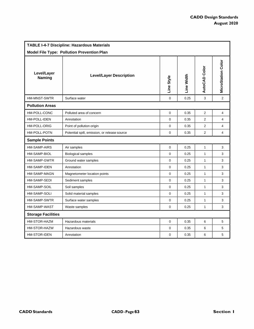
CADD - Page 63 Section I CADD Standards
CADD Design Standards
August 2020
TABLE I-4-7 Discipline: Hazardous Materials
Model File Type: Pollution Prevention Plan
Level/Layer
Naming
Level/Layer Description
Lin
e S
tyle
Lin
e W
idth
Au
toC
AD
Co
lor
Mic
roS
tati
on
Co
lor
HM-MNST-SWTR Surface water 0 0.25 3 2
Pollution Areas
HM-POLL-CONC Polluted area of concern 0 0.35 2 4
HM-POLL-IDEN Annotation 0 0.35 2 4
HM-POLL-ORIG Point of pollution origin 0 0.35 2 4
HM-POLL-POTN Potential spill, emission, or release source 0 0.35 2 4
Sample Points
HM-SAMP-AIRS Air samples 0 0.25 1 3
HM-SAMP-BIOL Biological samples 0 0.25 1 3
HM-SAMP-GWTR Ground water samples 0 0.25 1 3
HM-SAMP-IDEN Annotation 0 0.25 1 3
HM-SAMP-MAGN Magnetometer location points 0 0.25 1 3
HM-SAMP-SEDI Sediment samples 0 0.25 1 3
HM-SAMP-SOIL Soil samples 0 0.25 1 3
HM-SAMP-SOLI Solid material samples 0 0.25 1 3
HM-SAMP-SWTR Surface water samples 0 0.25 1 3
HM-SAMP-WAST Waste samples 0 0.25 1 3
Storage Facilities
HM-STOR-HAZM Hazardous materials 0 0.35 6 5
HM-STOR-HAZW Hazardous waste 0 0.35 6 5
HM-STOR-IDEN Annotation 0 0.35 6 5
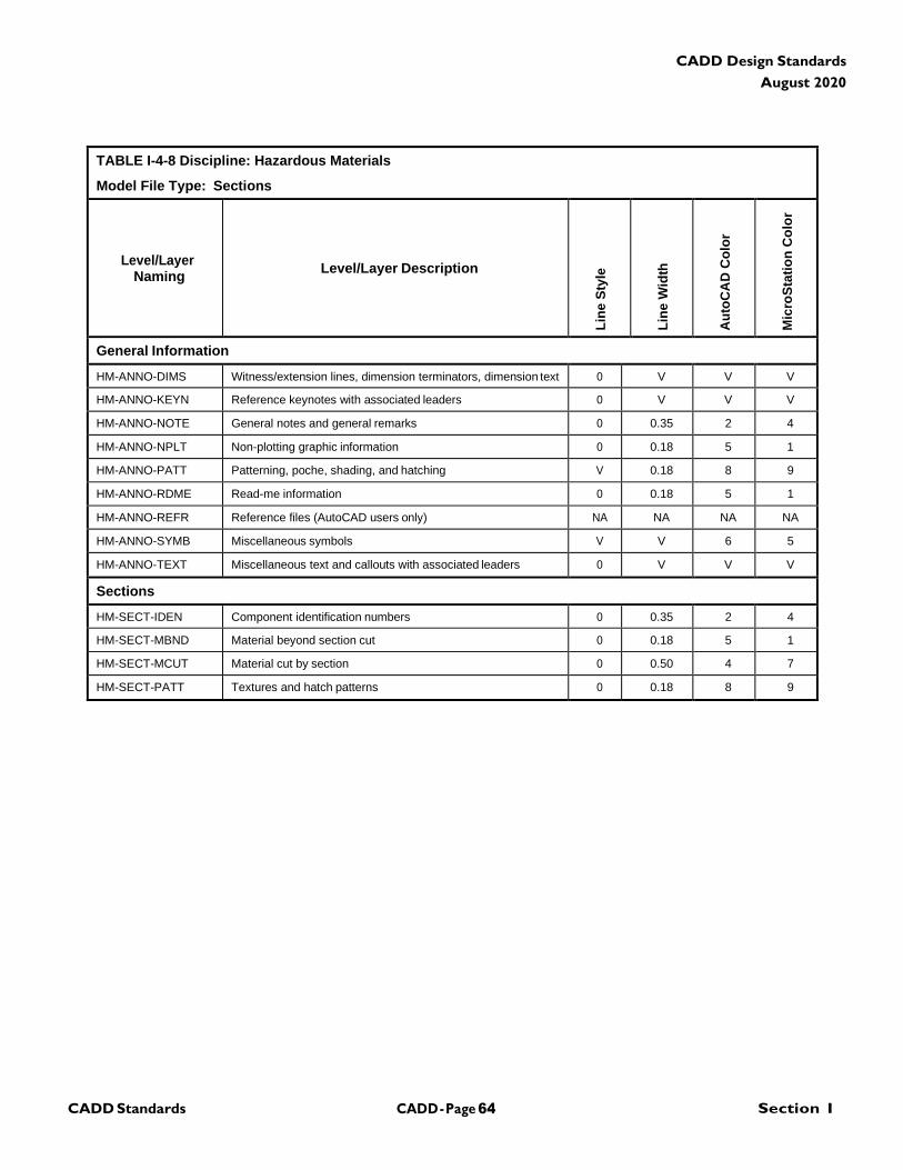
CADD - Page 64 Section I CADD Standards
CADD Design Standards
August 2020
TABLE I-4-8 Discipline: Hazardous Materials
Model File Type: Sections
Level/Layer
Naming
Level/Layer Description
Lin
e S
tyle
Lin
e W
idth
Au
toC
AD
Co
lor
Mic
roS
tati
on
Co
lor
General Information
HM-ANNO-DIMS Witness/extension lines, dimension terminators, dimension text 0 V V V
HM-ANNO-KEYN Reference keynotes with associated leaders 0 V V V
HM-ANNO-NOTE General notes and general remarks 0 0.35 2 4
HM-ANNO-NPLT Non-plotting graphic information 0 0.18 5 1
HM-ANNO-PATT Patterning, poche, shading, and hatching V 0.18 8 9
HM-ANNO-RDME Read-me information 0 0.18 5 1
HM-ANNO-REFR Reference files (AutoCAD users only) NA NA NA NA
HM-ANNO-SYMB Miscellaneous symbols V V 6 5
HM-ANNO-TEXT Miscellaneous text and callouts with associated leaders 0 V V V
Sections
HM-SECT-IDEN Component identification numbers 0 0.35 2 4
HM-SECT-MBND Material beyond section cut 0 0.18 5 1
HM-SECT-MCUT Material cut by section 0 0.50 4 7
HM-SECT-PATT Textures and hatch patterns 0 0.18 8 9
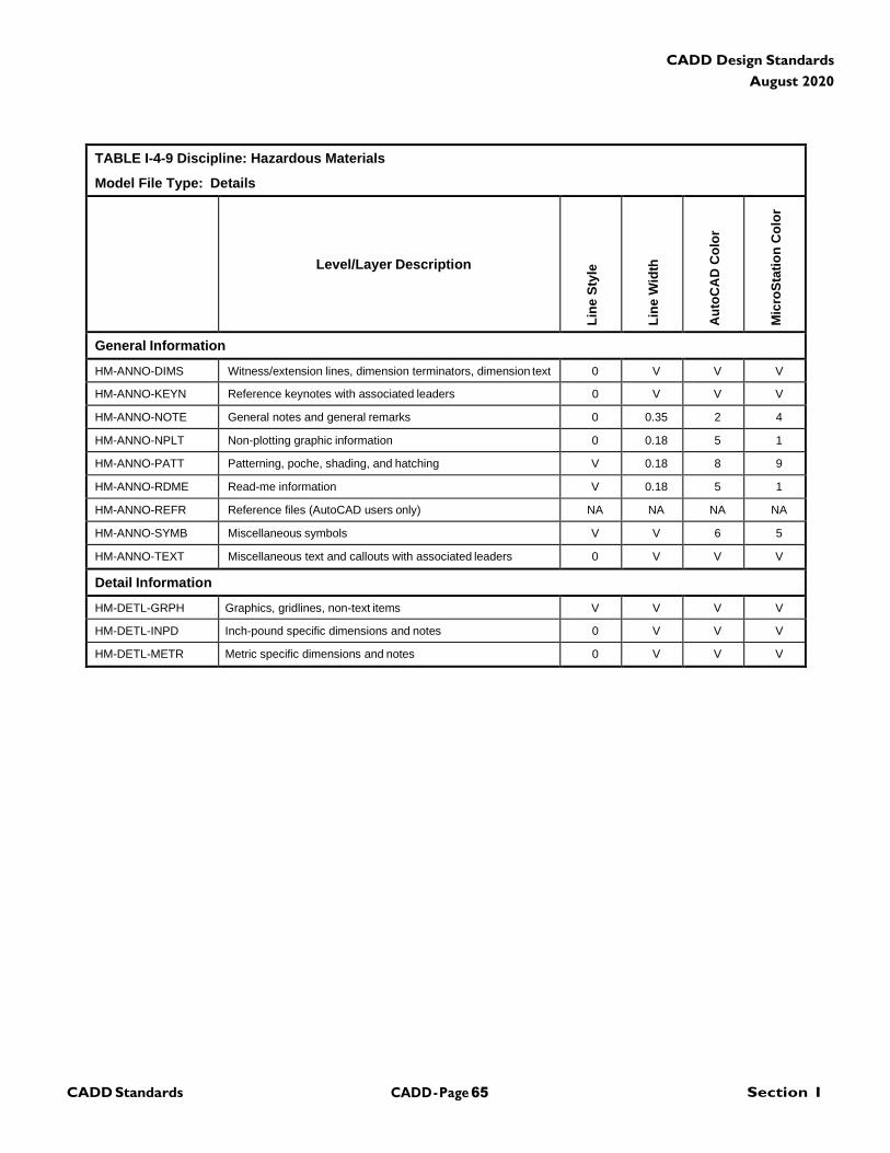
CADD - Page 65 Section I CADD Standards
CADD Design Standards
August 2020
TABLE I-4-9 Discipline: Hazardous Materials
Model File Type: Details
Level/Layer Description
Lin
e S
tyle
Lin
e W
idth
Au
toC
AD
Co
lor
Mic
roS
tati
on
Co
lor
General Information
HM-ANNO-DIMS Witness/extension lines, dimension terminators, dimension text 0 V V V
HM-ANNO-KEYN Reference keynotes with associated leaders 0 V V V
HM-ANNO-NOTE General notes and general remarks 0 0.35 2 4
HM-ANNO-NPLT Non-plotting graphic information 0 0.18 5 1
HM-ANNO-PATT Patterning, poche, shading, and hatching V 0.18 8 9
HM-ANNO-RDME Read-me information V 0.18 5 1
HM-ANNO-REFR Reference files (AutoCAD users only) NA NA NA NA
HM-ANNO-SYMB Miscellaneous symbols V V 6 5
HM-ANNO-TEXT Miscellaneous text and callouts with associated leaders 0 V V V
Detail Information
HM-DETL-GRPH Graphics, gridlines, non-text items V V V V
HM-DETL-INPD Inch-pound specific dimensions and notes 0 V V V
HM-DETL-METR Metric specific dimensions and notes 0 V V V
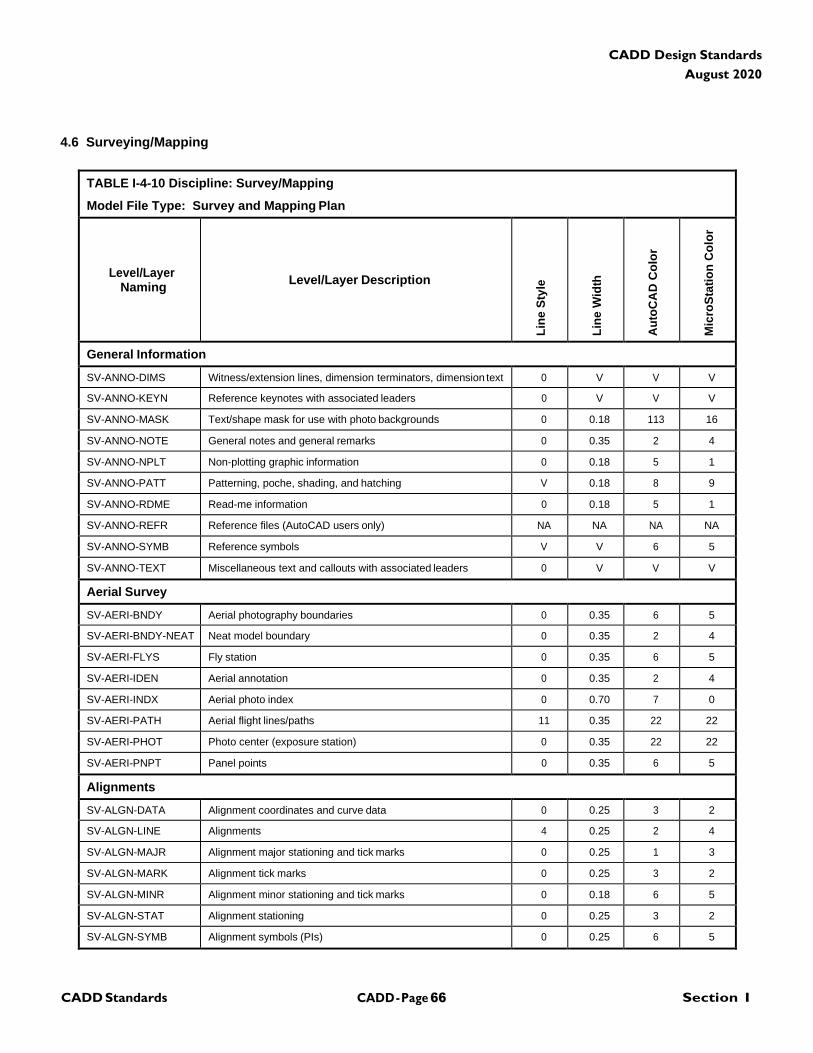
CADD - Page 66 Section I CADD Standards
CADD Design Standards
August 2020
4.6 Surveying/Mapping
TABLE I-4-10 Discipline: Survey/Mapping
Model File Type: Survey and Mapping Plan
Level/Layer
Naming
Level/Layer Description
Lin
e S
tyle
Lin
e W
idth
Au
toC
AD
Co
lor
Mic
roS
tati
on
Co
lor
General Information
SV-ANNO-DIMS Witness/extension lines, dimension terminators, dimension text 0 V V V
SV-ANNO-KEYN Reference keynotes with associated leaders 0 V V V
SV-ANNO-MASK Text/shape mask for use with photo backgrounds 0 0.18 113 16
SV-ANNO-NOTE General notes and general remarks 0 0.35 2 4
SV-ANNO-NPLT Non-plotting graphic information 0 0.18 5 1
SV-ANNO-PATT Patterning, poche, shading, and hatching V 0.18 8 9
SV-ANNO-RDME Read-me information 0 0.18 5 1
SV-ANNO-REFR Reference files (AutoCAD users only) NA NA NA NA
SV-ANNO-SYMB Reference symbols V V 6 5
SV-ANNO-TEXT Miscellaneous text and callouts with associated leaders 0 V V V
Aerial Survey
SV-AERI-BNDY Aerial photography boundaries 0 0.35 6 5
SV-AERI-BNDY-NEAT Neat model boundary 0 0.35 2 4
SV-AERI-FLYS Fly station 0 0.35 6 5
SV-AERI-IDEN Aerial annotation 0 0.35 2 4
SV-AERI-INDX Aerial photo index 0 0.70 7 0
SV-AERI-PATH Aerial flight lines/paths 11 0.35 22 22
SV-AERI-PHOT Photo center (exposure station) 0 0.35 22 22
SV-AERI-PNPT Panel points 0 0.35 6 5
Alignments
SV-ALGN-DATA Alignment coordinates and curve data 0 0.25 3 2
SV-ALGN-LINE Alignments 4 0.25 2 4
SV-ALGN-MAJR Alignment major stationing and tick marks 0 0.25 1 3
SV-ALGN-MARK Alignment tick marks 0 0.25 3 2
SV-ALGN-MINR Alignment minor stationing and tick marks 0 0.18 6 5
SV-ALGN-STAT Alignment stationing 0 0.25 3 2
SV-ALGN-SYMB Alignment symbols (PIs) 0 0.25 6 5
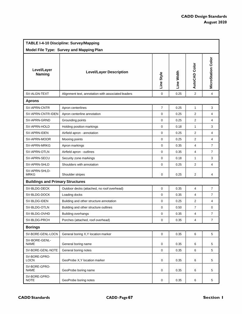
CADD - Page 67 Section I CADD Standards
CADD Design Standards
August 2020
TABLE I-4-10 Discipline: Survey/Mapping
Model File Type: Survey and Mapping Plan
Level/Layer
Naming
Level/Layer Description
Lin
e S
tyle
Lin
e W
idth
Au
toC
AD
Co
lor
Mic
roS
tati
on
Co
lor
SV-ALGN-TEXT Alignment text, annotation with associated leaders 0 0.25 2 4
Aprons
SV-APRN-CNTR Apron centerlines 7 0.25 1 3
SV-APRN-CNTR-IDEN Apron centerline annotation 0 0.25 2 4
SV-APRN-GRND Grounding points 0 0.25 2 4
SV-APRN-HOLD Holding position markings 0 0.18 1 3
SV-APRN-IDEN Airfield apron - annotation 0 0.25 2 4
SV-APRN-MOOR Mooring points 0 0.25 2 4
SV-APRN-MRKG Apron markings 0 0.35 4 7
SV-APRN-OTLN Airfield apron - outlines 0 0.35 4 7
SV-APRN-SECU Security zone markings 0 0.18 1 3
SV-APRN-SHLD Shoulders with annotation 0 0.25 2 4
SV-APRN-SHLD- MRKG
Shoulder stripes
0
0.25
2
4
Buildings and Primary Structures
SV-BLDG-DECK Outdoor decks (attached, no roof overhead) 0 0.35 4 7
SV-BLDG-DOCK Loading docks 0 0.35 4 7
SV-BLDG-IDEN Building and other structure annotation 0 0.25 2 4
SV-BLDG-OTLN Building and other structure outlines 0 0.50 7 0
SV-BLDG-OVHD Building overhangs 0 0.35 4 7
SV-BLDG-PRCH Porches (attached, roof overhead) 0 0.35 4 7
Borings
SV-BORE-GENL-LOCN General boring X,Y location marker 0 0.35 6 5
SV-BORE-GENL- NAME
General boring name
0
0.35
6
5
SV-BORE-GENL-NOTE General boring notes 0 0.35 6 5
SV-BORE-GPRO- LOCN
GeoProbe X,Y location marker
0
0.35
6
5
SV-BORE-GPRO- NAME
GeoProbe boring name
0
0.35
6
5
SV-BORE-GPRO- NOTE
GeoProbe boring notes
0
0.35
6
5
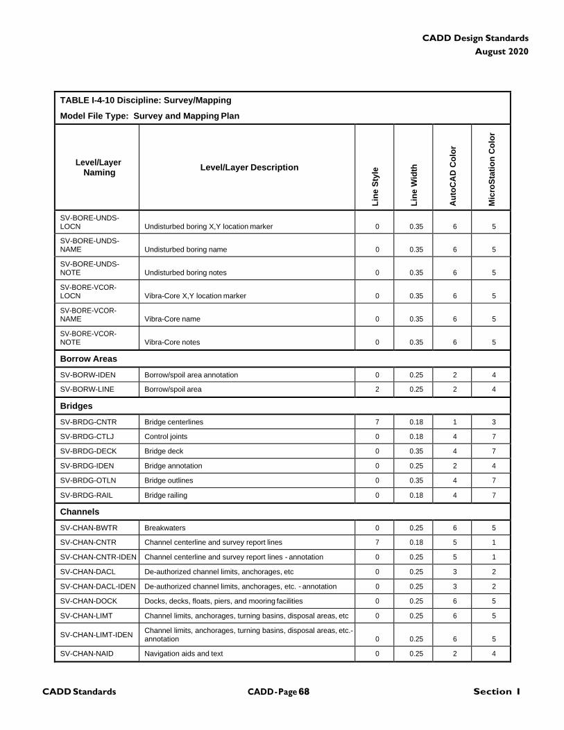
CADD - Page 68 Section I CADD Standards
CADD Design Standards
August 2020
TABLE I-4-10 Discipline: Survey/Mapping
Model File Type: Survey and Mapping Plan
Level/Layer
Naming
Level/Layer Description
Lin
e S
tyle
Lin
e W
idth
Au
toC
AD
Co
lor
Mic
roS
tati
on
Co
lor
SV-BORE-UNDS- LOCN
Undisturbed boring X,Y location marker
0
0.35
6
5
SV-BORE-UNDS- NAME
Undisturbed boring name
0
0.35
6
5
SV-BORE-UNDS- NOTE
Undisturbed boring notes
0
0.35
6
5
SV-BORE-VCOR- LOCN
Vibra-Core X,Y location marker
0
0.35
6
5
SV-BORE-VCOR- NAME
Vibra-Core name
0
0.35
6
5
SV-BORE-VCOR- NOTE
Vibra-Core notes
0
0.35
6
5
Borrow Areas
SV-BORW-IDEN Borrow/spoil area annotation 0 0.25 2 4
SV-BORW-LINE Borrow/spoil area 2 0.25 2 4
Bridges
SV-BRDG-CNTR Bridge centerlines 7 0.18 1 3
SV-BRDG-CTLJ Control joints 0 0.18 4 7
SV-BRDG-DECK Bridge deck 0 0.35 4 7
SV-BRDG-IDEN Bridge annotation 0 0.25 2 4
SV-BRDG-OTLN Bridge outlines 0 0.35 4 7
SV-BRDG-RAIL Bridge railing 0 0.18 4 7
Channels
SV-CHAN-BWTR Breakwaters 0 0.25 6 5
SV-CHAN-CNTR Channel centerline and survey report lines 7 0.18 5 1
SV-CHAN-CNTR-IDEN Channel centerline and survey report lines - annotation 0 0.25 5 1
SV-CHAN-DACL De-authorized channel limits, anchorages, etc 0 0.25 3 2
SV-CHAN-DACL-IDEN De-authorized channel limits, anchorages, etc. - annotation 0 0.25 3 2
SV-CHAN-DOCK Docks, decks, floats, piers, and mooring facilities 0 0.25 6 5
SV-CHAN-LIMT Channel limits, anchorages, turning basins, disposal areas, etc 0 0.25 6 5
SV-CHAN-LIMT-IDEN Channel limits, anchorages, turning basins, disposal areas, etc.- annotation
0
0.25
6
5
SV-CHAN-NAID Navigation aids and text 0 0.25 2 4
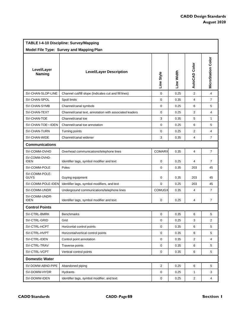
CADD - Page 69 Section I CADD Standards
CADD Design Standards
August 2020
TABLE I-4-10 Discipline: Survey/Mapping
Model File Type: Survey and Mapping Plan
Level/Layer
Naming
Level/Layer Description
Lin
e S
tyle
Lin
e W
idth
Au
toC
AD
Co
lor
Mic
roS
tati
on
Co
lor
SV-CHAN-SLOP-LINE Channel cut/fill slope (Indicates cut and fill lines) 0 0.25 2 4
SV-CHAN-SPOL Spoil limits 0 0.35 4 7
SV-CHAN-SYMB Channel/canal symbols 0 0.25 6 5
SV-CHAN-TEXT Channel/canal text, annotation with associated leaders 0 0.25 2 4
SV-CHAN-TOE Channel/canal toe 3 0.35 5 1
SV-CHAN-TOE~-IDEN Channel/canal toe annotation 0 0.25 6 5
SV-CHAN-TURN Turning points 0 0.25 2 4
SV-CHAN-WIDE Channel/canal widener 3 0.35 4 7
Communications
SV-COMM-OVHD Overhead communications/telephone lines COMARX 0.35 4 7
SV-COMM-OVHD- IDEN
Identifier tags, symbol modifier and text
0
0.25
4
7
SV-COMM-POLE Poles 0 0.35 203 45
SV-COMM-POLE- GUYS
Guying equipment
0
0.35
203
45
SV-COMM-POLE-IDEN Identifier tags, symbol modifiers, and text 0 0.25 203 45
SV-COMM-UNDR Underground communications/telephone lines COMUGX 0.35 4 7
SV-COMM-UNDR- IDEN
Identifier tags, symbol modifier and text
0
0.25
4
7
Control Points
SV-CTRL-BMRK Benchmarks 0 0.35 6 5
SV-CTRL-GRID Grid 0 0.25 3 2
SV-CTRL-HCPT Horizontal control points 0 0.35 6 5
SV-CTRL-HVPT Horizontal/vertical control points 0 0.35 6 5
SV-CTRL-IDEN Control point annotation 0 0.35 2 4
SV-CTRL-TRAV Traverse points 0 0.35 6 5
SV-CTRL-VCPT Vertical control points 0 0.35 6 5
Domestic Water
SV-DOMW-ABND-PIPE Abandoned piping 2 0.25 6 5
SV-DOMW-HYDR Hydrants 0 0.25 1 3
SV-DOMW-IDEN Identifier tags, symbol modifier, and text 0 0.25 2 4
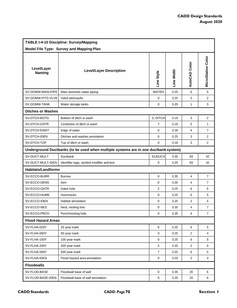
CADD - Page 70 Section I CADD Standards
CADD Design Standards
August 2020
TABLE I-4-10 Discipline: Survey/Mapping
Model File Type: Survey and Mapping Plan
Level/Layer
Naming
Level/Layer Description
Lin
e S
tyle
Lin
e W
idth
Au
toC
AD
Co
lor
Mic
roS
tati
on
Co
lor
SV-DOMW-MAIN-PIPE Main domestic water piping WATRX 0.25 6 5
SV-DOMW-PITS-VLVE Valve pits/vaults 0 0.25 3 2
SV-DOMW-TANK Water storage tanks 0 0.25 1 3
Ditches or Washes
SV-DTCH-BOTD Bottom of ditch or wash 0, DITCH 0.18 3 2
SV-DTCH-CNTR Centerline of ditch or wash 7 0.18 5 1
SV-DTCH-EWAT Edge of water 0 0.18 4 7
SV-DTCH-IDEN Ditches and washes annotation 0 0.25 3 2
SV-DTCH-TOP Top of ditch or wash 0 0.18 3 2
Underground Ductbanks (to be used when multiple systems are in one ductbank system)
SV-DUCT-MULT Ductbank EUDUCX 0.35 83 42
SV-DUCT-MULT-IDEN Identifier tags, symbol modifier and text 0 0.25 83 42
Habitats/Landforms
SV-ECCO-BURR Burrow 0 0.35 4 7
SV-ECCO-DENS Den 0 0.35 4 7
SV-ECCO-GATR Gator hole 2 0.25 6 5
SV-ECCO-HUMK Hummocks 0 0.25 6 5
SV-ECCO-IDEN Habitat annotation 0 0.25 2 4
SV-ECCO-NES Nest, nesting tree 0 0.35 4 7
SV-ECCO-PRCH Perch/nesting hole 0 0.35 4 7
Flood Hazard Areas
SV-FLHA-025Y 25 year mark 6 0.25 6 5
SV-FLHA-050Y 50 year mark 3 0.25 2 4
SV-FLHA-100Y 100 year mark 0 0.25 6 5
SV-FLHA-200Y 200 year mark 2 0.25 2 4
SV-FLHA-500Y 500 year mark 7 0.25 6 5
SV-FLHA-IDEN Flood hazard area annotation 0 0.25 2 4
Floodwalls
SV-FLOD-BASE Floodwall base of wall 0 0.35 20 6
SV-FLOD-BASE-IDEN Floodwall base of wall annotation 0 0.25 20 6
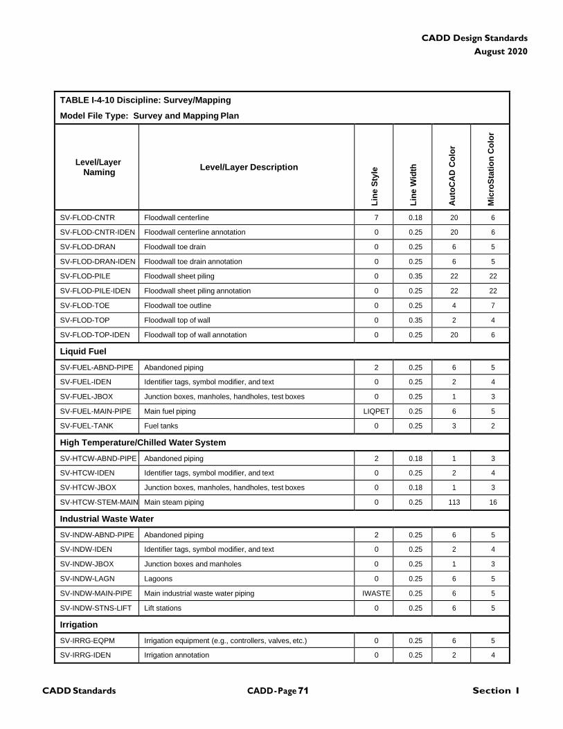
CADD - Page 71 Section I CADD Standards
CADD Design Standards
August 2020
TABLE I-4-10 Discipline: Survey/Mapping
Model File Type: Survey and Mapping Plan
Level/Layer
Naming
Level/Layer Description
Lin
e S
tyle
Lin
e W
idth
Au
toC
AD
Co
lor
Mic
roS
tati
on
Co
lor
SV-FLOD-CNTR Floodwall centerline 7 0.18 20 6
SV-FLOD-CNTR-IDEN Floodwall centerline annotation 0 0.25 20 6
SV-FLOD-DRAN Floodwall toe drain 0 0.25 6 5
SV-FLOD-DRAN-IDEN Floodwall toe drain annotation 0 0.25 6 5
SV-FLOD-PILE Floodwall sheet piling 0 0.35 22 22
SV-FLOD-PILE-IDEN Floodwall sheet piling annotation 0 0.25 22 22
SV-FLOD-TOE Floodwall toe outline 0 0.25 4 7
SV-FLOD-TOP Floodwall top of wall 0 0.35 2 4
SV-FLOD-TOP-IDEN Floodwall top of wall annotation 0 0.25 20 6
Liquid Fuel
SV-FUEL-ABND-PIPE Abandoned piping 2 0.25 6 5
SV-FUEL-IDEN Identifier tags, symbol modifier, and text 0 0.25 2 4
SV-FUEL-JBOX Junction boxes, manholes, handholes, test boxes 0 0.25 1 3
SV-FUEL-MAIN-PIPE Main fuel piping LIQPET 0.25 6 5
SV-FUEL-TANK Fuel tanks 0 0.25 3 2
High Temperature/Chilled Water System
SV-HTCW-ABND-PIPE Abandoned piping 2 0.18 1 3
SV-HTCW-IDEN Identifier tags, symbol modifier, and text 0 0.25 2 4
SV-HTCW-JBOX Junction boxes, manholes, handholes, test boxes 0 0.18 1 3
SV-HTCW-STEM-MAIN Main steam piping 0 0.25 113 16
Industrial Waste Water
SV-INDW-ABND-PIPE Abandoned piping 2 0.25 6 5
SV-INDW-IDEN Identifier tags, symbol modifier, and text 0 0.25 2 4
SV-INDW-JBOX Junction boxes and manholes 0 0.25 1 3
SV-INDW-LAGN Lagoons 0 0.25 6 5
SV-INDW-MAIN-PIPE Main industrial waste water piping IWASTE 0.25 6 5
SV-INDW-STNS-LIFT Lift stations 0 0.25 6 5
Irrigation
SV-IRRG-EQPM Irrigation equipment (e.g., controllers, valves, etc.) 0 0.25 6 5
SV-IRRG-IDEN Irrigation annotation 0 0.25 2 4
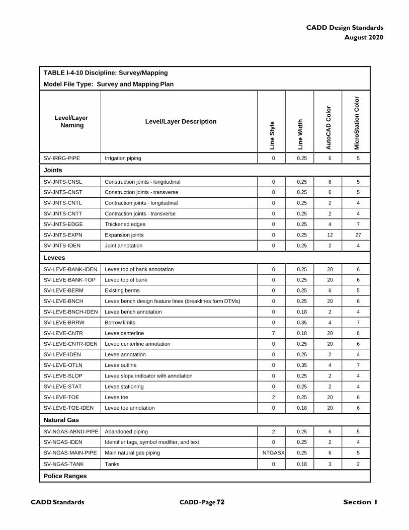
CADD - Page 72 Section I CADD Standards
CADD Design Standards
August 2020
TABLE I-4-10 Discipline: Survey/Mapping
Model File Type: Survey and Mapping Plan
Level/Layer
Naming
Level/Layer Description
Lin
e S
tyle
Lin
e W
idth
Au
toC
AD
Co
lor
Mic
roS
tati
on
Co
lor
SV-IRRG-PIPE Irrigation piping 0 0.25 6 5
Joints
SV-JNTS-CNSL Construction joints - longitudinal 0 0.25 6 5
SV-JNTS-CNST Construction joints - transverse 0 0.25 6 5
SV-JNTS-CNTL Contraction joints - longitudinal 0 0.25 2 4
SV-JNTS-CNTT Contraction joints - transverse 0 0.25 2 4
SV-JNTS-EDGE Thickened edges 0 0.25 4 7
SV-JNTS-EXPN Expansion joints 0 0.25 12 27
SV-JNTS-IDEN Joint annotation 0 0.25 2 4
Levees
SV-LEVE-BANK-IDEN Levee top of bank annotation 0 0.25 20 6
SV-LEVE-BANK-TOP Levee top of bank 0 0.25 20 6
SV-LEVE-BERM Existing berms 0 0.25 6 5
SV-LEVE-BNCH Levee bench design feature lines (breaklines form DTMs) 0 0.25 20 6
SV-LEVE-BNCH-IDEN Levee bench annotation 0 0.18 2 4
SV-LEVE-BRRW Borrow limits 0 0.35 4 7
SV-LEVE-CNTR Levee centerline 7 0.18 20 6
SV-LEVE-CNTR-IDEN Levee centerline annotation 0 0.25 20 6
SV-LEVE-IDEN Levee annotation 0 0.25 2 4
SV-LEVE-OTLN Levee outline 0 0.35 4 7
SV-LEVE-SLOP Levee slope indicator with annotation 0 0.25 2 4
SV-LEVE-STAT Levee stationing 0 0.25 2 4
SV-LEVE-TOE Levee toe 2 0.25 20 6
SV-LEVE-TOE-IDEN Levee toe annotation 0 0.18 20 6
Natural Gas
SV-NGAS-ABND-PIPE Abandoned piping 2 0.25 6 5
SV-NGAS-IDEN Identifier tags, symbol modifier, and text 0 0.25 2 4
SV-NGAS-MAIN-PIPE Main natural gas piping NTGASX 0.25 6 5
SV-NGAS-TANK Tanks 0 0.18 3 2
Police Ranges
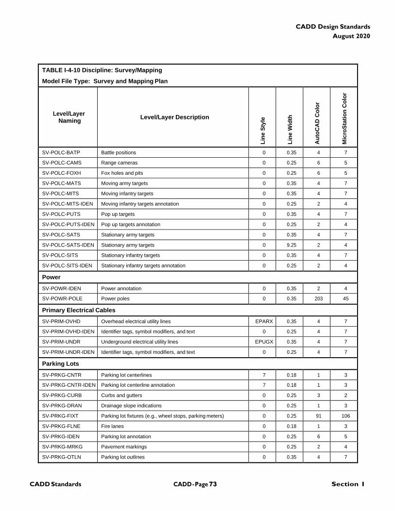
CADD - Page 73 Section I CADD Standards
CADD Design Standards
August 2020
TABLE I-4-10 Discipline: Survey/Mapping
Model File Type: Survey and Mapping Plan
Level/Layer
Naming
Level/Layer Description
Lin
e S
tyle
Lin
e W
idth
Au
toC
AD
Co
lor
Mic
roS
tati
on
Co
lor
SV-POLC-BATP Battle positions 0 0.35 4 7
SV-POLC-CAMS Range cameras 0 0.25 6 5
SV-POLC-FOXH Fox holes and pits 0 0.25 6 5
SV-POLC-MATS Moving army targets 0 0.35 4 7
SV-POLC-MITS Moving infantry targets 0 0.35 4 7
SV-POLC-MITS-IDEN Moving infantry targets annotation 0 0.25 2 4
SV-POLC-PUTS Pop up targets 0 0.35 4 7
SV-POLC-PUTS-IDEN Pop up targets annotation 0 0.25 2 4
SV-POLC-SATS Stationary army targets 0 0.35 4 7
SV-POLC-SATS-IDEN Stationary army targets 0 9.25 2 4
SV-POLC-SITS Stationary infantry targets 0 0.35 4 7
SV-POLC-SITS-IDEN Stationary infantry targets annotation 0 0.25 2 4
Power
SV-POWR-IDEN Power annotation 0 0.35 2 4
SV-POWR-POLE Power poles 0 0.35 203 45
Primary Electrical Cables
SV-PRIM-OVHD Overhead electrical utility lines EPARX 0.35 4 7
SV-PRIM-OVHD-IDEN Identifier tags, symbol modifiers, and text 0 0.25 4 7
SV-PRIM-UNDR Underground electrical utility lines EPUGX 0.35 4 7
SV-PRIM-UNDR-IDEN Identifier tags, symbol modifiers, and text 0 0.25 4 7
Parking Lots
SV-PRKG-CNTR Parking lot centerlines 7 0.18 1 3
SV-PRKG-CNTR-IDEN Parking lot centerline annotation 7 0.18 1 3
SV-PRKG-CURB Curbs and gutters 0 0.25 3 2
SV-PRKG-DRAN Drainage slope indications 0 0.25 1 3
SV-PRKG-FIXT Parking lot fixtures (e.g., wheel stops, parking meters) 0 0.25 91 106
SV-PRKG-FLNE Fire lanes 0 0.18 1 3
SV-PRKG-IDEN Parking lot annotation 0 0.25 6 5
SV-PRKG-MRKG Pavement markings 0 0.25 2 4
SV-PRKG-OTLN Parking lot outlines 0 0.35 4 7
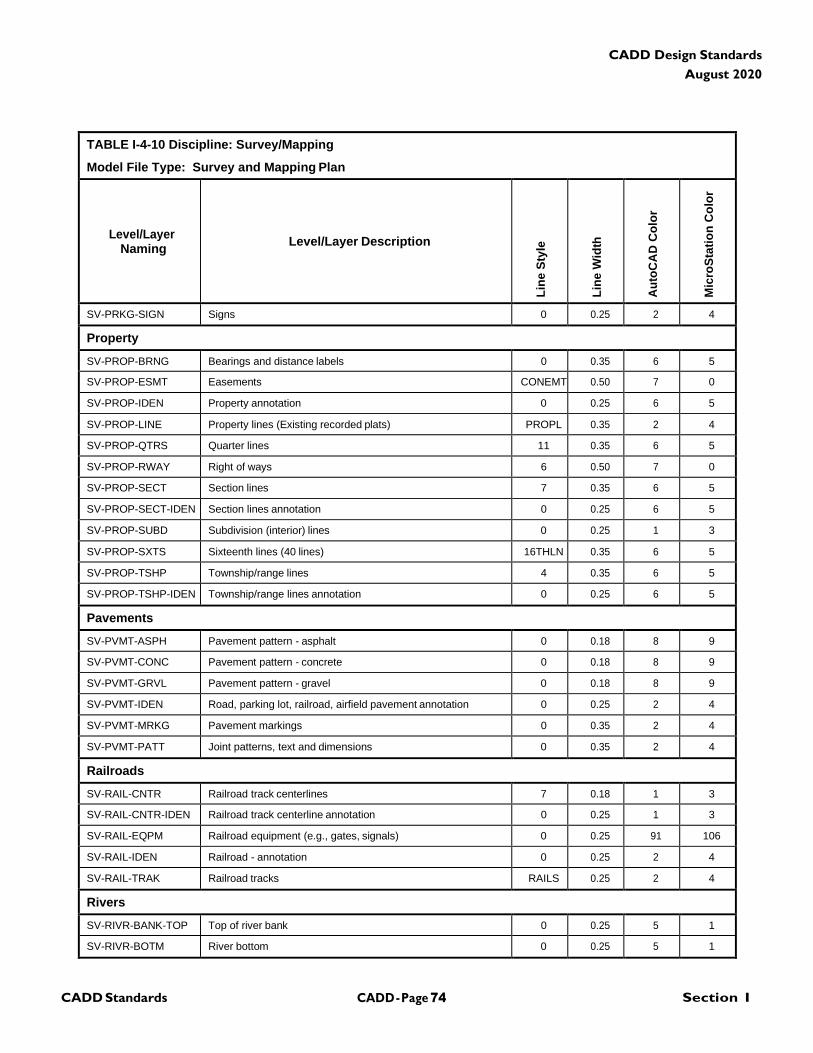
CADD - Page 74 Section I CADD Standards
CADD Design Standards
August 2020
TABLE I-4-10 Discipline: Survey/Mapping
Model File Type: Survey and Mapping Plan
Level/Layer
Naming
Level/Layer Description
Lin
e S
tyle
Lin
e W
idth
Au
toC
AD
Co
lor
Mic
roS
tati
on
Co
lor
SV-PRKG-SIGN Signs 0 0.25 2 4
Property
SV-PROP-BRNG Bearings and distance labels 0 0.35 6 5
SV-PROP-ESMT Easements CONEMT 0.50 7 0
SV-PROP-IDEN Property annotation 0 0.25 6 5
SV-PROP-LINE Property lines (Existing recorded plats) PROPL 0.35 2 4
SV-PROP-QTRS Quarter lines 11 0.35 6 5
SV-PROP-RWAY Right of ways 6 0.50 7 0
SV-PROP-SECT Section lines 7 0.35 6 5
SV-PROP-SECT-IDEN Section lines annotation 0 0.25 6 5
SV-PROP-SUBD Subdivision (interior) lines 0 0.25 1 3
SV-PROP-SXTS Sixteenth lines (40 lines) 16THLN 0.35 6 5
SV-PROP-TSHP Township/range lines 4 0.35 6 5
SV-PROP-TSHP-IDEN Township/range lines annotation 0 0.25 6 5
Pavements
SV-PVMT-ASPH Pavement pattern - asphalt 0 0.18 8 9
SV-PVMT-CONC Pavement pattern - concrete 0 0.18 8 9
SV-PVMT-GRVL Pavement pattern - gravel 0 0.18 8 9
SV-PVMT-IDEN Road, parking lot, railroad, airfield pavement annotation 0 0.25 2 4
SV-PVMT-MRKG Pavement markings 0 0.35 2 4
SV-PVMT-PATT Joint patterns, text and dimensions 0 0.35 2 4
Railroads
SV-RAIL-CNTR Railroad track centerlines 7 0.18 1 3
SV-RAIL-CNTR-IDEN Railroad track centerline annotation 0 0.25 1 3
SV-RAIL-EQPM Railroad equipment (e.g., gates, signals) 0 0.25 91 106
SV-RAIL-IDEN Railroad - annotation 0 0.25 2 4
SV-RAIL-TRAK Railroad tracks RAILS 0.25 2 4
Rivers
SV-RIVR-BANK-TOP Top of river bank 0 0.25 5 1
SV-RIVR-BOTM River bottom 0 0.25 5 1
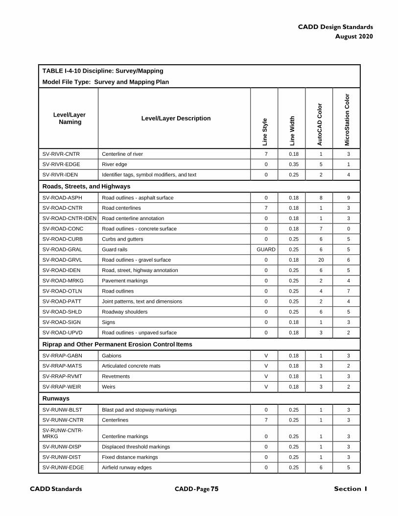
CADD - Page 75 Section I CADD Standards
CADD Design Standards
August 2020
TABLE I-4-10 Discipline: Survey/Mapping
Model File Type: Survey and Mapping Plan
Level/Layer
Naming
Level/Layer Description
Lin
e S
tyle
Lin
e W
idth
Au
toC
AD
Co
lor
Mic
roS
tati
on
Co
lor
SV-RIVR-CNTR Centerline of river 7 0.18 1 3
SV-RIVR-EDGE River edge 0 0.35 5 1
SV-RIVR-IDEN Identifier tags, symbol modifiers, and text 0 0.25 2 4
Roads, Streets, and Highways
SV-ROAD-ASPH Road outlines - asphalt surface 0 0.18 8 9
SV-ROAD-CNTR Road centerlines 7 0.18 1 3
SV-ROAD-CNTR-IDEN Road centerline annotation 0 0.18 1 3
SV-ROAD-CONC Road outlines - concrete surface 0 0.18 7 0
SV-ROAD-CURB Curbs and gutters 0 0.25 6 5
SV-ROAD-GRAL Guard rails GUARD 0.25 6 5
SV-ROAD-GRVL Road outlines - gravel surface 0 0.18 20 6
SV-ROAD-IDEN Road, street, highway annotation 0 0.25 6 5
SV-ROAD-MRKG Pavement markings 0 0.25 2 4
SV-ROAD-OTLN Road outlines 0 0.25 4 7
SV-ROAD-PATT Joint patterns, text and dimensions 0 0.25 2 4
SV-ROAD-SHLD Roadway shoulders 0 0.25 6 5
SV-ROAD-SIGN Signs 0 0.18 1 3
SV-ROAD-UPVD Road outlines - unpaved surface 0 0.18 3 2
Riprap and Other Permanent Erosion Control Items
SV-RRAP-GABN Gabions V 0.18 1 3
SV-RRAP-MATS Articulated concrete mats V 0.18 3 2
SV-RRAP-RVMT Revetments V 0.18 1 3
SV-RRAP-WEIR Weirs V 0.18 3 2
Runways
SV-RUNW-BLST Blast pad and stopway markings 0 0.25 1 3
SV-RUNW-CNTR Centerlines 7 0.25 1 3
SV-RUNW-CNTR- MRKG
Centerline markings
0
0.25
1
3
SV-RUNW-DISP Displaced threshold markings 0 0.25 1 3
SV-RUNW-DIST Fixed distance markings 0 0.25 1 3
SV-RUNW-EDGE Airfield runway edges 0 0.25 6 5
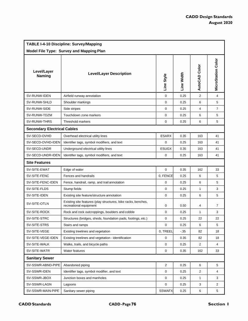
CADD - Page 76 Section I CADD Standards
CADD Design Standards
August 2020
TABLE I-4-10 Discipline: Survey/Mapping
Model File Type: Survey and Mapping Plan
Level/Layer
Naming
Level/Layer Description
Lin
e S
tyle
Lin
e W
idth
Au
toC
AD
Co
lor
Mic
roS
tati
on
Co
lor
SV-RUNW-IDEN Airfield runway annotation 0 0.25 2 4
SV-RUNW-SHLD Shoulder markings 0 0.25 6 5
SV-RUNW-SIDE Side stripes 0 0.25 4 7
SV-RUNW-TDZM Touchdown zone markers 0 0.25 6 5
SV-RUNW-THRS Threshold markers 0 0.25 6 5
Secondary Electrical Cables
SV-SECD-OVHD Overhead electrical utility lines ESARX 0.35 163 41
SV-SECD-OVHD-IDEN Identifier tags, symbol modifiers, and text 0 0.25 163 41
SV-SECD-UNDR Underground electrical utility lines ESUGX 0.35 163 41
SV-SECD-UNDR-IDEN Identifier tags, symbol modifiers, and text 0 0.25 163 41
Site Features
SV-SITE-EWAT Edge of water 0 0.35 162 33
SV-SITE-FENC Fences and handrails 0, FENCE 0.25 6 5
SV-SITE-FENC-IDEN Fence, handrail, ramp, and trail annotation 0 0.25 6 5
SV-SITE-FLDS Stump fields 0 0.25 1 3
SV-SITE-IDEN Existing site feature/structure annotation 0 0.25 6 5
SV-SITE-OTLN Existing site features (play structures, bike racks, benches, recreational equipment
0
0.50
4
7
SV-SITE-ROCK Rock and rock outcroppings, boulders and cobble 0 0.25 1 3
SV-SITE-STRC Structures (bridges, sheds, foundation pads, footings, etc.) 0 0.25 22 22
SV-SITE-STRS Stairs and ramps 0 0.25 6 5
SV-SITE-VEGE Existing treelines and vegetation 0, TREEL -.35 82 18
SV-SITE-VEGE-IDEN Existing treelines and vegetation - identification 0 0.35 82 18
SV-SITE-WALK Walks, trails, and bicycle paths 0 0.25 2 4
SV-SITE-WATR Water features 0 0.35 162 33
Sanitary Sewer
SV-SSWR-ABND-PIPE Abandoned piping 2 0.25 6 5
SV-SSWR-IDEN Identifier tags, symbol modifier, and text 0 0.25 2 4
SV-SSWR-JBOX Junction boxes and manholes 0 0.25 1 3
SV-SSWR-LAGN Lagoons 0 0.25 3 2
SV-SSWR-MAIN-PIPE Sanitary sewer piping SSWAFX 0.25 6 5
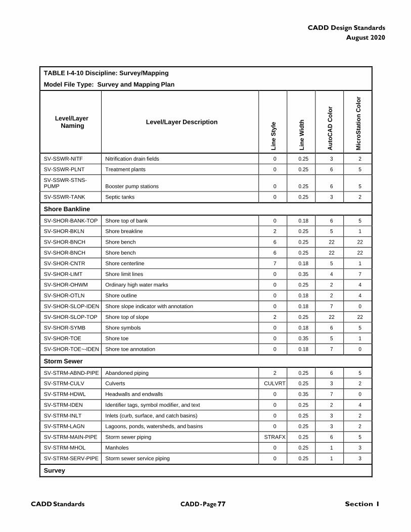
CADD - Page 77 Section I CADD Standards
CADD Design Standards
August 2020
TABLE I-4-10 Discipline: Survey/Mapping
Model File Type: Survey and Mapping Plan
Level/Layer
Naming
Level/Layer Description
Lin
e S
tyle
Lin
e W
idth
Au
toC
AD
Co
lor
Mic
roS
tati
on
Co
lor
SV-SSWR-NITF Nitrification drain fields 0 0.25 3 2
SV-SSWR-PLNT Treatment plants 0 0.25 6 5
SV-SSWR-STNS- PUMP
Booster pump stations
0
0.25
6
5
SV-SSWR-TANK Septic tanks 0 0.25 3 2
Shore Bankline
SV-SHOR-BANK-TOP Shore top of bank 0 0.18 6 5
SV-SHOR-BKLN Shore breakline 2 0.25 5 1
SV-SHOR-BNCH Shore bench 6 0.25 22 22
SV-SHOR-BNCH Shore bench 6 0.25 22 22
SV-SHOR-CNTR Shore centerline 7 0.18 5 1
SV-SHOR-LIMT Shore limit lines 0 0.35 4 7
SV-SHOR-OHWM Ordinary high water marks 0 0.25 2 4
SV-SHOR-OTLN Shore outline 0 0.18 2 4
SV-SHOR-SLOP-IDEN Shore slope indicator with annotation 0 0.18 7 0
SV-SHOR-SLOP-TOP Shore top of slope 2 0.25 22 22
SV-SHOR-SYMB Shore symbols 0 0.18 6 5
SV-SHOR-TOE Shore toe 0 0.35 5 1
SV-SHOR-TOE~-IDEN Shore toe annotation 0 0.18 7 0
Storm Sewer
SV-STRM-ABND-PIPE Abandoned piping 2 0.25 6 5
SV-STRM-CULV Culverts CULVRT 0.25 3 2
SV-STRM-HDWL Headwalls and endwalls 0 0.35 7 0
SV-STRM-IDEN Identifier tags, symbol modifier, and text 0 0.25 2 4
SV-STRM-INLT Inlets (curb, surface, and catch basins) 0 0.25 3 2
SV-STRM-LAGN Lagoons, ponds, watersheds, and basins 0 0.25 3 2
SV-STRM-MAIN-PIPE Storm sewer piping STRAFX 0.25 6 5
SV-STRM-MHOL Manholes 0 0.25 1 3
SV-STRM-SERV-PIPE Storm sewer service piping 0 0.25 1 3
Survey
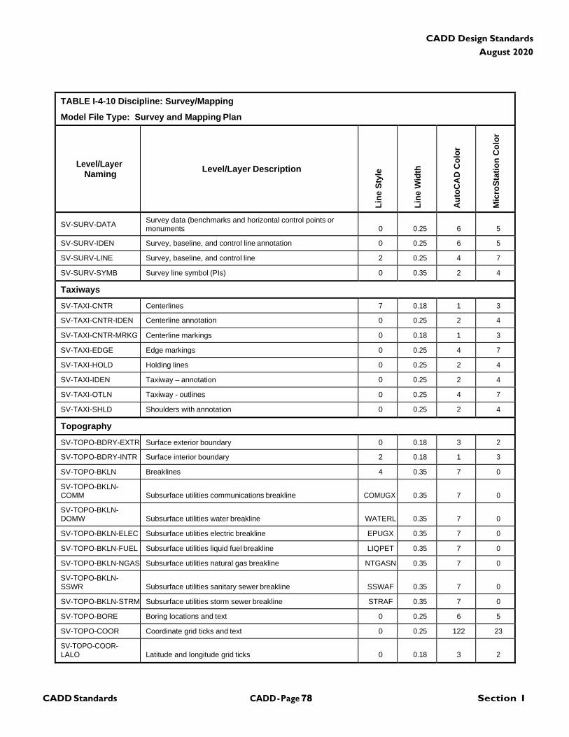
CADD - Page 78 Section I CADD Standards
CADD Design Standards
August 2020
TABLE I-4-10 Discipline: Survey/Mapping
Model File Type: Survey and Mapping Plan
Level/Layer
Naming
Level/Layer Description
Lin
e S
tyle
Lin
e W
idth
Au
toC
AD
Co
lor
Mic
roS
tati
on
Co
lor
SV-SURV-DATA Survey data (benchmarks and horizontal control points or monuments
0
0.25
6
5
SV-SURV-IDEN Survey, baseline, and control line annotation 0 0.25 6 5
SV-SURV-LINE Survey, baseline, and control line 2 0.25 4 7
SV-SURV-SYMB Survey line symbol (PIs) 0 0.35 2 4
Taxiways
SV-TAXI-CNTR Centerlines 7 0.18 1 3
SV-TAXI-CNTR-IDEN Centerline annotation 0 0.25 2 4
SV-TAXI-CNTR-MRKG Centerline markings 0 0.18 1 3
SV-TAXI-EDGE Edge markings 0 0.25 4 7
SV-TAXI-HOLD Holding lines 0 0.25 2 4
SV-TAXI-IDEN Taxiway – annotation 0 0.25 2 4
SV-TAXI-OTLN Taxiway - outlines 0 0.25 4 7
SV-TAXI-SHLD Shoulders with annotation 0 0.25 2 4
Topography
SV-TOPO-BDRY-EXTR Surface exterior boundary 0 0.18 3 2
SV-TOPO-BDRY-INTR Surface interior boundary 2 0.18 1 3
SV-TOPO-BKLN Breaklines 4 0.35 7 0
SV-TOPO-BKLN- COMM
Subsurface utilities communications breakline
COMUGX
0.35
7
0
SV-TOPO-BKLN- DOMW
Subsurface utilities water breakline
WATERL
0.35
7
0
SV-TOPO-BKLN-ELEC Subsurface utilities electric breakline EPUGX 0.35 7 0
SV-TOPO-BKLN-FUEL Subsurface utilities liquid fuel breakline LIQPET 0.35 7 0
SV-TOPO-BKLN-NGAS Subsurface utilities natural gas breakline NTGASN 0.35 7 0
SV-TOPO-BKLN- SSWR
Subsurface utilities sanitary sewer breakline
SSWAF
0.35
7
0
SV-TOPO-BKLN-STRM Subsurface utilities storm sewer breakline STRAF 0.35 7 0
SV-TOPO-BORE Boring locations and text 0 0.25 6 5
SV-TOPO-COOR Coordinate grid ticks and text 0 0.25 122 23
SV-TOPO-COOR- LALO
Latitude and longitude grid ticks
0
0.18
3
2
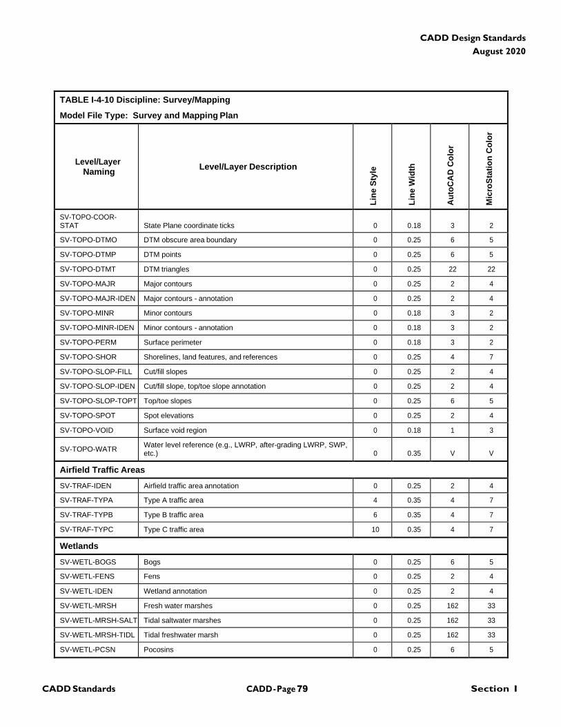
CADD - Page 79 Section I CADD Standards
CADD Design Standards
August 2020
TABLE I-4-10 Discipline: Survey/Mapping
Model File Type: Survey and Mapping Plan
Level/Layer
Naming
Level/Layer Description
Lin
e S
tyle
Lin
e W
idth
Au
toC
AD
Co
lor
Mic
roS
tati
on
Co
lor
SV-TOPO-COOR- STAT
State Plane coordinate ticks
0
0.18
3
2
SV-TOPO-DTMO DTM obscure area boundary 0 0.25 6 5
SV-TOPO-DTMP DTM points 0 0.25 6 5
SV-TOPO-DTMT DTM triangles 0 0.25 22 22
SV-TOPO-MAJR Major contours 0 0.25 2 4
SV-TOPO-MAJR-IDEN Major contours - annotation 0 0.25 2 4
SV-TOPO-MINR Minor contours 0 0.18 3 2
SV-TOPO-MINR-IDEN Minor contours - annotation 0 0.18 3 2
SV-TOPO-PERM Surface perimeter 0 0.18 3 2
SV-TOPO-SHOR Shorelines, land features, and references 0 0.25 4 7
SV-TOPO-SLOP-FILL Cut/fill slopes 0 0.25 2 4
SV-TOPO-SLOP-IDEN Cut/fill slope, top/toe slope annotation 0 0.25 2 4
SV-TOPO-SLOP-TOPT Top/toe slopes 0 0.25 6 5
SV-TOPO-SPOT Spot elevations 0 0.25 2 4
SV-TOPO-VOID Surface void region 0 0.18 1 3
SV-TOPO-WATR Water level reference (e.g., LWRP, after-grading LWRP, SWP, etc.)
0
0.35
V
V
Airfield Traffic Areas
SV-TRAF-IDEN Airfield traffic area annotation 0 0.25 2 4
SV-TRAF-TYPA Type A traffic area 4 0.35 4 7
SV-TRAF-TYPB Type B traffic area 6 0.35 4 7
SV-TRAF-TYPC Type C traffic area 10 0.35 4 7
Wetlands
SV-WETL-BOGS Bogs 0 0.25 6 5
SV-WETL-FENS Fens 0 0.25 2 4
SV-WETL-IDEN Wetland annotation 0 0.25 2 4
SV-WETL-MRSH Fresh water marshes 0 0.25 162 33
SV-WETL-MRSH-SALT Tidal saltwater marshes 0 0.25 162 33
SV-WETL-MRSH-TIDL Tidal freshwater marsh 0 0.25 162 33
SV-WETL-PCSN Pocosins 0 0.25 6 5
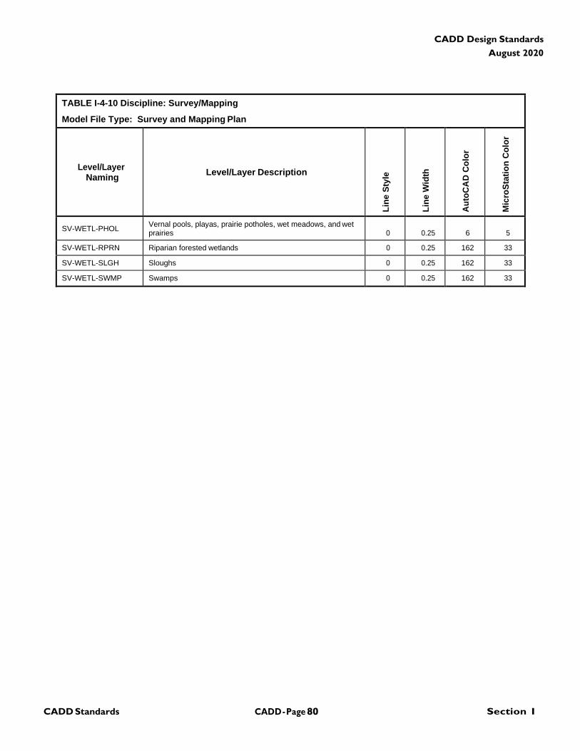
CADD - Page 80 Section I CADD Standards
CADD Design Standards
August 2020
TABLE I-4-10 Discipline: Survey/Mapping
Model File Type: Survey and Mapping Plan
Level/Layer
Naming
Level/Layer Description
Lin
e S
tyle
Lin
e W
idth
Au
toC
AD
Co
lor
Mic
roS
tati
on
Co
lor
SV-WETL-PHOL Vernal pools, playas, prairie potholes, wet meadows, and wet prairies
0
0.25
6
5
SV-WETL-RPRN Riparian forested wetlands 0 0.25 162 33
SV-WETL-SLGH Sloughs 0 0.25 162 33
SV-WETL-SWMP Swamps 0 0.25 162 33
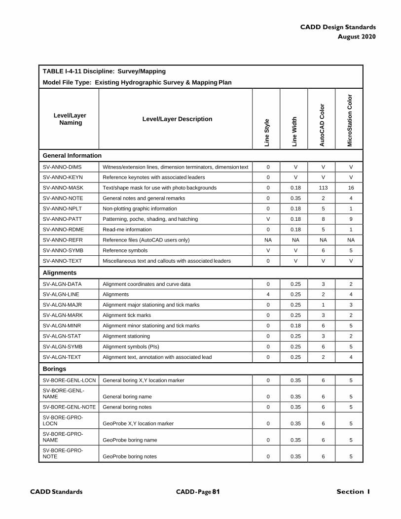
CADD - Page 81 Section I CADD Standards
CADD Design Standards
August 2020
TABLE I-4-11 Discipline: Survey/Mapping
Model File Type: Existing Hydrographic Survey & Mapping Plan
Level/Layer
Naming
Level/Layer Description
Lin
e S
tyle
Lin
e W
idth
Au
toC
AD
Co
lor
Mic
roS
tati
on
Co
lor
General Information
SV-ANNO-DIMS Witness/extension lines, dimension terminators, dimension text 0 V V V
SV-ANNO-KEYN Reference keynotes with associated leaders 0 V V V
SV-ANNO-MASK Text/shape mask for use with photo backgrounds 0 0.18 113 16
SV-ANNO-NOTE General notes and general remarks 0 0.35 2 4
SV-ANNO-NPLT Non-plotting graphic information 0 0.18 5 1
SV-ANNO-PATT Patterning, poche, shading, and hatching V 0.18 8 9
SV-ANNO-RDME Read-me information 0 0.18 5 1
SV-ANNO-REFR Reference files (AutoCAD users only) NA NA NA NA
SV-ANNO-SYMB Reference symbols V V 6 5
SV-ANNO-TEXT Miscellaneous text and callouts with associated leaders 0 V V V
Alignments
SV-ALGN-DATA Alignment coordinates and curve data 0 0.25 3 2
SV-ALGN-LINE Alignments 4 0.25 2 4
SV-ALGN-MAJR Alignment major stationing and tick marks 0 0.25 1 3
SV-ALGN-MARK Alignment tick marks 0 0.25 3 2
SV-ALGN-MINR Alignment minor stationing and tick marks 0 0.18 6 5
SV-ALGN-STAT Alignment stationing 0 0.25 3 2
SV-ALGN-SYMB Alignment symbols (PIs) 0 0.25 6 5
SV-ALGN-TEXT Alignment text, annotation with associated lead 0 0.25 2 4
Borings
SV-BORE-GENL-LOCN General boring X,Y location marker 0 0.35 6 5
SV-BORE-GENL- NAME
General boring name
0
0.35
6
5
SV-BORE-GENL-NOTE General boring notes 0 0.35 6 5
SV-BORE-GPRO- LOCN
GeoProbe X,Y location marker
0
0.35
6
5
SV-BORE-GPRO- NAME
GeoProbe boring name
0
0.35
6
5
SV-BORE-GPRO- NOTE
GeoProbe boring notes
0
0.35
6
5
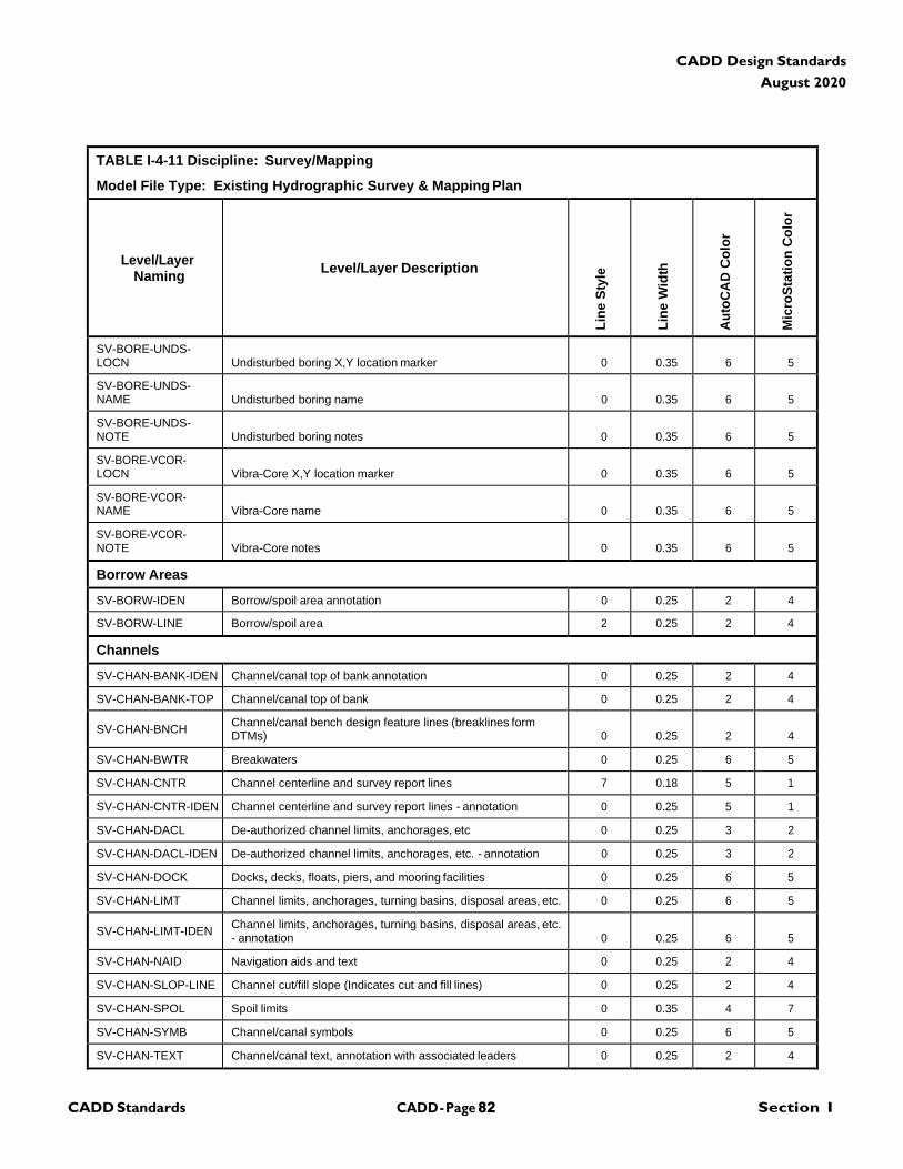
CADD - Page 82 Section I CADD Standards
CADD Design Standards
August 2020
TABLE I-4-11 Discipline: Survey/Mapping
Model File Type: Existing Hydrographic Survey & Mapping Plan
Level/Layer
Naming
Level/Layer Description
Lin
e S
tyle
Lin
e W
idth
Au
toC
AD
Co
lor
Mic
roS
tati
on
Co
lor
SV-BORE-UNDS- LOCN
Undisturbed boring X,Y location marker
0
0.35
6
5
SV-BORE-UNDS- NAME
Undisturbed boring name
0
0.35
6
5
SV-BORE-UNDS- NOTE
Undisturbed boring notes
0
0.35
6
5
SV-BORE-VCOR- LOCN
Vibra-Core X,Y location marker
0
0.35
6
5
SV-BORE-VCOR- NAME
Vibra-Core name
0
0.35
6
5
SV-BORE-VCOR- NOTE
Vibra-Core notes
0
0.35
6
5
Borrow Areas
SV-BORW-IDEN Borrow/spoil area annotation 0 0.25 2 4
SV-BORW-LINE Borrow/spoil area 2 0.25 2 4
Channels
SV-CHAN-BANK-IDEN Channel/canal top of bank annotation 0 0.25 2 4
SV-CHAN-BANK-TOP Channel/canal top of bank 0 0.25 2 4
SV-CHAN-BNCH Channel/canal bench design feature lines (breaklines form DTMs)
0
0.25
2
4
SV-CHAN-BWTR Breakwaters 0 0.25 6 5
SV-CHAN-CNTR Channel centerline and survey report lines 7 0.18 5 1
SV-CHAN-CNTR-IDEN Channel centerline and survey report lines - annotation 0 0.25 5 1
SV-CHAN-DACL De-authorized channel limits, anchorages, etc 0 0.25 3 2
SV-CHAN-DACL-IDEN De-authorized channel limits, anchorages, etc. - annotation 0 0.25 3 2
SV-CHAN-DOCK Docks, decks, floats, piers, and mooring facilities 0 0.25 6 5
SV-CHAN-LIMT Channel limits, anchorages, turning basins, disposal areas, etc. 0 0.25 6 5
SV-CHAN-LIMT-IDEN Channel limits, anchorages, turning basins, disposal areas, etc. - annotation
0
0.25
6
5
SV-CHAN-NAID Navigation aids and text 0 0.25 2 4
SV-CHAN-SLOP-LINE Channel cut/fill slope (Indicates cut and fill lines) 0 0.25 2 4
SV-CHAN-SPOL Spoil limits 0 0.35 4 7
SV-CHAN-SYMB Channel/canal symbols 0 0.25 6 5
SV-CHAN-TEXT Channel/canal text, annotation with associated leaders 0 0.25 2 4
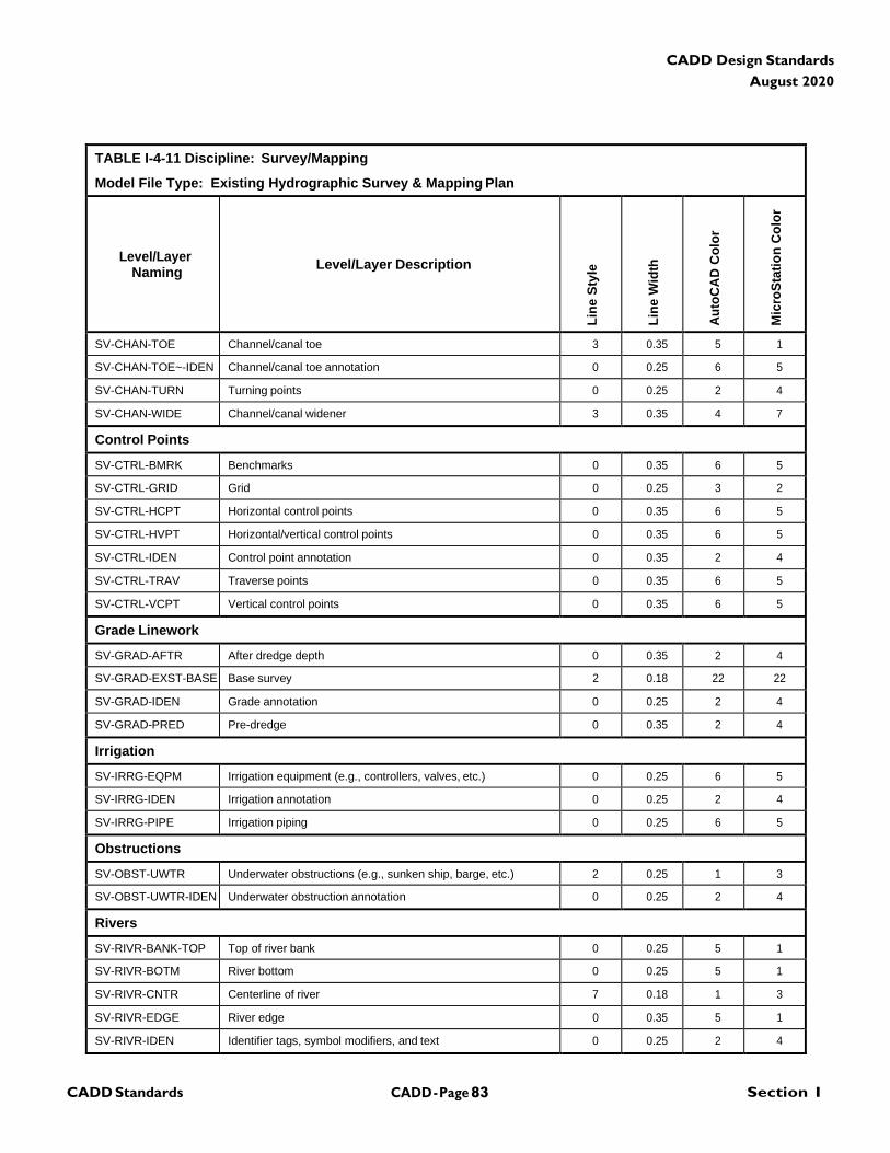
CADD - Page 83 Section I CADD Standards
CADD Design Standards
August 2020
TABLE I-4-11 Discipline: Survey/Mapping
Model File Type: Existing Hydrographic Survey & Mapping Plan
Level/Layer
Naming
Level/Layer Description
Lin
e S
tyle
Lin
e W
idth
Au
toC
AD
Co
lor
Mic
roS
tati
on
Co
lor
SV-CHAN-TOE Channel/canal toe 3 0.35 5 1
SV-CHAN-TOE~-IDEN Channel/canal toe annotation 0 0.25 6 5
SV-CHAN-TURN Turning points 0 0.25 2 4
SV-CHAN-WIDE Channel/canal widener 3 0.35 4 7
Control Points
SV-CTRL-BMRK Benchmarks 0 0.35 6 5
SV-CTRL-GRID Grid 0 0.25 3 2
SV-CTRL-HCPT Horizontal control points 0 0.35 6 5
SV-CTRL-HVPT Horizontal/vertical control points 0 0.35 6 5
SV-CTRL-IDEN Control point annotation 0 0.35 2 4
SV-CTRL-TRAV Traverse points 0 0.35 6 5
SV-CTRL-VCPT Vertical control points 0 0.35 6 5
Grade Linework
SV-GRAD-AFTR After dredge depth 0 0.35 2 4
SV-GRAD-EXST-BASE Base survey 2 0.18 22 22
SV-GRAD-IDEN Grade annotation 0 0.25 2 4
SV-GRAD-PRED Pre-dredge 0 0.35 2 4
Irrigation
SV-IRRG-EQPM Irrigation equipment (e.g., controllers, valves, etc.) 0 0.25 6 5
SV-IRRG-IDEN Irrigation annotation 0 0.25 2 4
SV-IRRG-PIPE Irrigation piping 0 0.25 6 5
Obstructions
SV-OBST-UWTR Underwater obstructions (e.g., sunken ship, barge, etc.) 2 0.25 1 3
SV-OBST-UWTR-IDEN Underwater obstruction annotation 0 0.25 2 4
Rivers
SV-RIVR-BANK-TOP Top of river bank 0 0.25 5 1
SV-RIVR-BOTM River bottom 0 0.25 5 1
SV-RIVR-CNTR Centerline of river 7 0.18 1 3
SV-RIVR-EDGE River edge 0 0.35 5 1
SV-RIVR-IDEN Identifier tags, symbol modifiers, and text 0 0.25 2 4
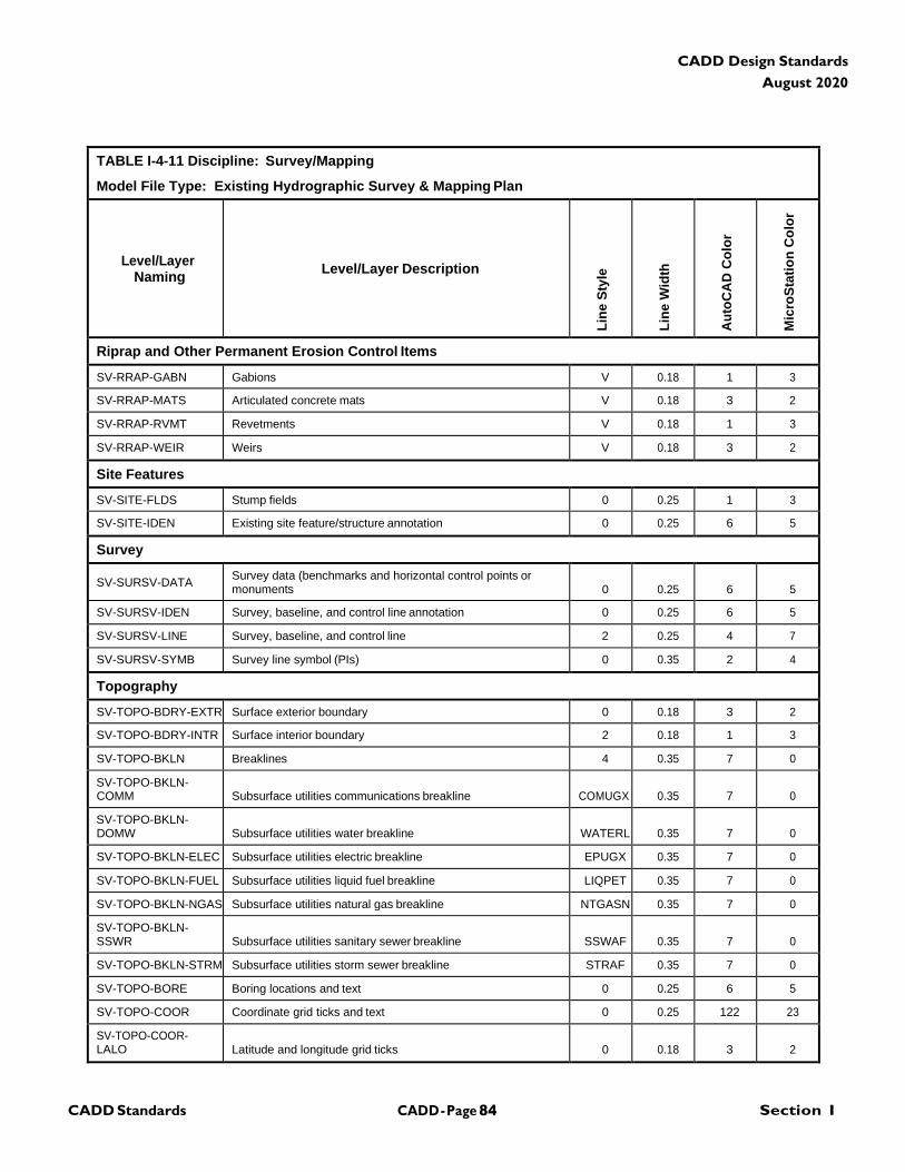
CADD - Page 84 Section I CADD Standards
CADD Design Standards
August 2020
TABLE I-4-11 Discipline: Survey/Mapping
Model File Type: Existing Hydrographic Survey & Mapping Plan
Level/Layer
Naming
Level/Layer Description
Lin
e S
tyle
Lin
e W
idth
Au
toC
AD
Co
lor
Mic
roS
tati
on
Co
lor
Riprap and Other Permanent Erosion Control Items
SV-RRAP-GABN Gabions V 0.18 1 3
SV-RRAP-MATS Articulated concrete mats V 0.18 3 2
SV-RRAP-RVMT Revetments V 0.18 1 3
SV-RRAP-WEIR Weirs V 0.18 3 2
Site Features
SV-SITE-FLDS Stump fields 0 0.25 1 3
SV-SITE-IDEN Existing site feature/structure annotation 0 0.25 6 5
Survey
SV-SURSV-DATA Survey data (benchmarks and horizontal control points or monuments
0
0.25
6
5
SV-SURSV-IDEN Survey, baseline, and control line annotation 0 0.25 6 5
SV-SURSV-LINE Survey, baseline, and control line 2 0.25 4 7
SV-SURSV-SYMB Survey line symbol (PIs) 0 0.35 2 4
Topography
SV-TOPO-BDRY-EXTR Surface exterior boundary 0 0.18 3 2
SV-TOPO-BDRY-INTR Surface interior boundary 2 0.18 1 3
SV-TOPO-BKLN Breaklines 4 0.35 7 0
SV-TOPO-BKLN- COMM
Subsurface utilities communications breakline
COMUGX
0.35
7
0
SV-TOPO-BKLN- DOMW
Subsurface utilities water breakline
WATERL
0.35
7
0
SV-TOPO-BKLN-ELEC Subsurface utilities electric breakline EPUGX 0.35 7 0
SV-TOPO-BKLN-FUEL Subsurface utilities liquid fuel breakline LIQPET 0.35 7 0
SV-TOPO-BKLN-NGAS Subsurface utilities natural gas breakline NTGASN 0.35 7 0
SV-TOPO-BKLN- SSWR
Subsurface utilities sanitary sewer breakline
SSWAF
0.35
7
0
SV-TOPO-BKLN-STRM Subsurface utilities storm sewer breakline STRAF 0.35 7 0
SV-TOPO-BORE Boring locations and text 0 0.25 6 5
SV-TOPO-COOR Coordinate grid ticks and text 0 0.25 122 23
SV-TOPO-COOR- LALO
Latitude and longitude grid ticks
0
0.18
3
2
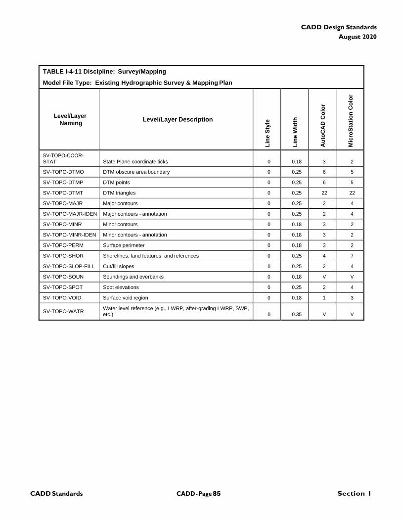
CADD - Page 85 Section I CADD Standards
CADD Design Standards
August 2020
TABLE I-4-11 Discipline: Survey/Mapping
Model File Type: Existing Hydrographic Survey & Mapping Plan
Level/Layer
Naming
Level/Layer Description
Lin
e S
tyle
Lin
e W
idth
Au
toC
AD
Co
lor
Mic
roS
tati
on
Co
lor
SV-TOPO-COOR- STAT
State Plane coordinate ticks
0
0.18
3
2
SV-TOPO-DTMO DTM obscure area boundary 0 0.25 6 5
SV-TOPO-DTMP DTM points 0 0.25 6 5
SV-TOPO-DTMT DTM triangles 0 0.25 22 22
SV-TOPO-MAJR Major contours 0 0.25 2 4
SV-TOPO-MAJR-IDEN Major contours - annotation 0 0.25 2 4
SV-TOPO-MINR Minor contours 0 0.18 3 2
SV-TOPO-MINR-IDEN Minor contours - annotation 0 0.18 3 2
SV-TOPO-PERM Surface perimeter 0 0.18 3 2
SV-TOPO-SHOR Shorelines, land features, and references 0 0.25 4 7
SV-TOPO-SLOP-FILL Cut/fill slopes 0 0.25 2 4
SV-TOPO-SOUN Soundings and overbanks 0 0.18 V V
SV-TOPO-SPOT Spot elevations 0 0.25 2 4
SV-TOPO-VOID Surface void region 0 0.18 1 3
SV-TOPO-WATR Water level reference (e.g., LWRP, after-grading LWRP, SWP, etc.)
0
0.35
V
V
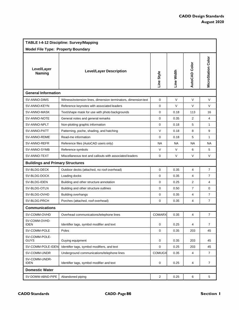
CADD - Page 86 Section I CADD Standards
CADD Design Standards
August 2020
TABLE I-4-12 Discipline: Survey/Mapping
Model File Type: Property Boundary
Level/Layer
Naming
Level/Layer Description
Lin
e S
tyle
Lin
e W
idth
Au
toC
AD
Co
lor
Mic
roS
tati
on
Co
lor
General Information
SV-ANNO-DIMS Witness/extension lines, dimension terminators, dimension text 0 V V V
SV-ANNO-KEYN Reference keynotes with associated leaders 0 V V V
SV-ANNO-MASK Text/shape mask for use with photo backgrounds 0 0.18 113 16
SV-ANNO-NOTE General notes and general remarks 0 0.35 2 4
SV-ANNO-NPLT Non-plotting graphic information 0 0.18 5 1
SV-ANNO-PATT Patterning, poche, shading, and hatching V 0.18 8 9
SV-ANNO-RDME Read-me information 0 0.18 5 1
SV-ANNO-REFR Reference files (AutoCAD users only) NA NA NA NA
SV-ANNO-SYMB Reference symbols V V 6 5
SV-ANNO-TEXT Miscellaneous text and callouts with associated leaders 0 V V V
Buildings and Primary Structures
SV-BLDG-DECK Outdoor decks (attached, no roof overhead) 0 0.35 4 7
SV-BLDG-DOCK Loading docks 0 0.35 4 7
SV-BLDG-IDEN Building and other structure annotation 0 0.25 2 4
SV-BLDG-OTLN Building and other structure outlines 0 0.50 7 0
SV-BLDG-OVHD Building overhangs 0 0.35 4 7
SV-BLDG-PRCH Porches (attached, roof overhead) 0 0.35 4 7
Communications
SV-COMM-OVHD Overhead communications/telephone lines COMARX 0.35 4 7
SV-COMM-OVHD- IDEN
Identifier tags, symbol modifier and text
0
0.25
4
7
SV-COMM-POLE Poles 0 0.35 203 45
SV-COMM-POLE- GUYS
Guying equipment
0
0.35
203
45
SV-COMM-POLE-IDEN Identifier tags, symbol modifiers, and text 0 0.25 203 45
SV-COMM-UNDR Underground communications/telephone lines COMUGX 0.35 4 7
SV-COMM-UNDR- IDEN
Identifier tags, symbol modifier and text
0
0.25
4
7
Domestic Water
SV-DOMW-ABND-PIPE Abandoned piping 2 0.25 6 5
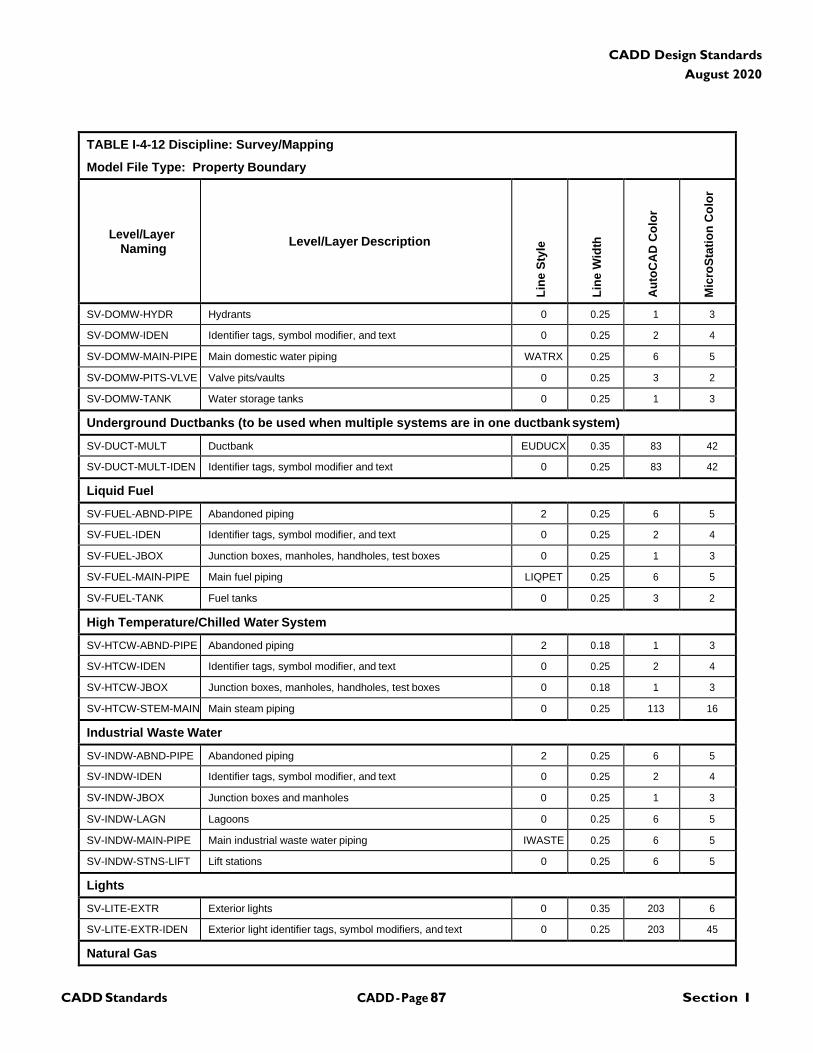
CADD - Page 87 Section I CADD Standards
CADD Design Standards
August 2020
TABLE I-4-12 Discipline: Survey/Mapping
Model File Type: Property Boundary
Level/Layer
Naming
Level/Layer Description
Lin
e S
tyle
Lin
e W
idth
Au
toC
AD
Co
lor
Mic
roS
tati
on
Co
lor
SV-DOMW-HYDR Hydrants 0 0.25 1 3
SV-DOMW-IDEN Identifier tags, symbol modifier, and text 0 0.25 2 4
SV-DOMW-MAIN-PIPE Main domestic water piping WATRX 0.25 6 5
SV-DOMW-PITS-VLVE Valve pits/vaults 0 0.25 3 2
SV-DOMW-TANK Water storage tanks 0 0.25 1 3
Underground Ductbanks (to be used when multiple systems are in one ductbank system)
SV-DUCT-MULT Ductbank EUDUCX 0.35 83 42
SV-DUCT-MULT-IDEN Identifier tags, symbol modifier and text 0 0.25 83 42
Liquid Fuel
SV-FUEL-ABND-PIPE Abandoned piping 2 0.25 6 5
SV-FUEL-IDEN Identifier tags, symbol modifier, and text 0 0.25 2 4
SV-FUEL-JBOX Junction boxes, manholes, handholes, test boxes 0 0.25 1 3
SV-FUEL-MAIN-PIPE Main fuel piping LIQPET 0.25 6 5
SV-FUEL-TANK Fuel tanks 0 0.25 3 2
High Temperature/Chilled Water System
SV-HTCW-ABND-PIPE Abandoned piping 2 0.18 1 3
SV-HTCW-IDEN Identifier tags, symbol modifier, and text 0 0.25 2 4
SV-HTCW-JBOX Junction boxes, manholes, handholes, test boxes 0 0.18 1 3
SV-HTCW-STEM-MAIN Main steam piping 0 0.25 113 16
Industrial Waste Water
SV-INDW-ABND-PIPE Abandoned piping 2 0.25 6 5
SV-INDW-IDEN Identifier tags, symbol modifier, and text 0 0.25 2 4
SV-INDW-JBOX Junction boxes and manholes 0 0.25 1 3
SV-INDW-LAGN Lagoons 0 0.25 6 5
SV-INDW-MAIN-PIPE Main industrial waste water piping IWASTE 0.25 6 5
SV-INDW-STNS-LIFT Lift stations 0 0.25 6 5
Lights
SV-LITE-EXTR Exterior lights 0 0.35 203 6
SV-LITE-EXTR-IDEN Exterior light identifier tags, symbol modifiers, and text 0 0.25 203 45
Natural Gas
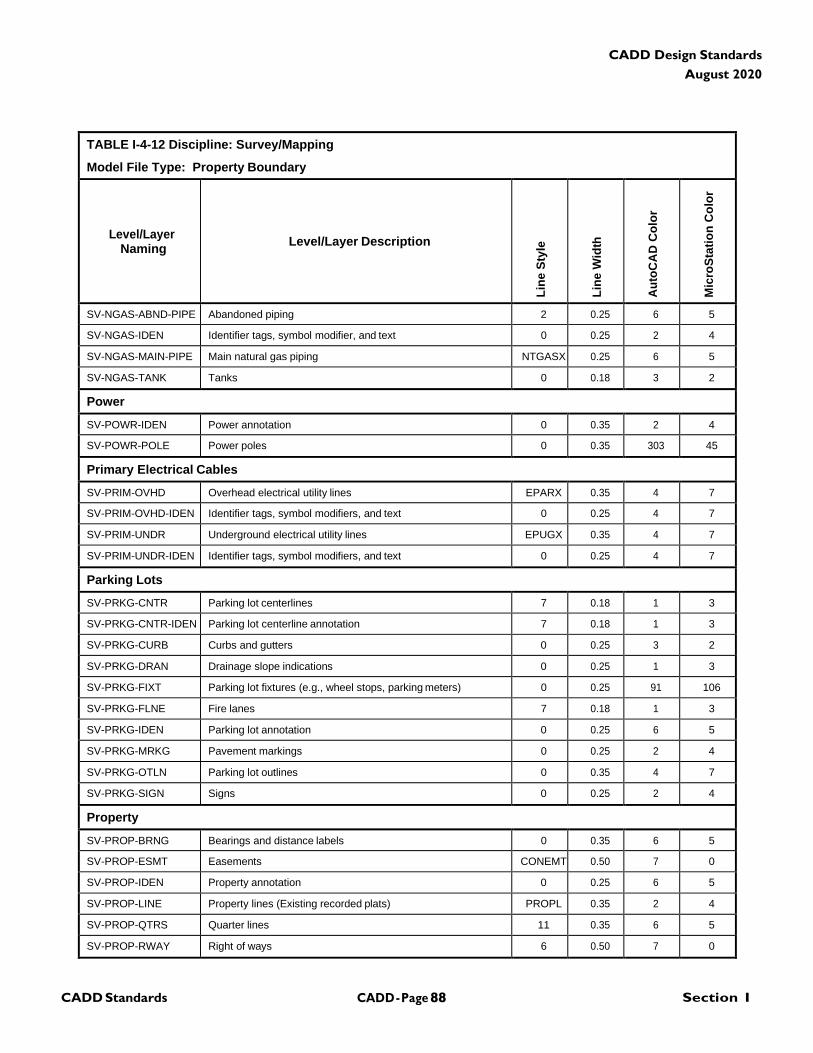
CADD - Page 88 Section I CADD Standards
CADD Design Standards
August 2020
TABLE I-4-12 Discipline: Survey/Mapping
Model File Type: Property Boundary
Level/Layer
Naming
Level/Layer Description
Lin
e S
tyle
Lin
e W
idth
Au
toC
AD
Co
lor
Mic
roS
tati
on
Co
lor
SV-NGAS-ABND-PIPE Abandoned piping 2 0.25 6 5
SV-NGAS-IDEN Identifier tags, symbol modifier, and text 0 0.25 2 4
SV-NGAS-MAIN-PIPE Main natural gas piping NTGASX 0.25 6 5
SV-NGAS-TANK Tanks 0 0.18 3 2
Power
SV-POWR-IDEN Power annotation 0 0.35 2 4
SV-POWR-POLE Power poles 0 0.35 303 45
Primary Electrical Cables
SV-PRIM-OVHD Overhead electrical utility lines EPARX 0.35 4 7
SV-PRIM-OVHD-IDEN Identifier tags, symbol modifiers, and text 0 0.25 4 7
SV-PRIM-UNDR Underground electrical utility lines EPUGX 0.35 4 7
SV-PRIM-UNDR-IDEN Identifier tags, symbol modifiers, and text 0 0.25 4 7
Parking Lots
SV-PRKG-CNTR Parking lot centerlines 7 0.18 1 3
SV-PRKG-CNTR-IDEN Parking lot centerline annotation 7 0.18 1 3
SV-PRKG-CURB Curbs and gutters 0 0.25 3 2
SV-PRKG-DRAN Drainage slope indications 0 0.25 1 3
SV-PRKG-FIXT Parking lot fixtures (e.g., wheel stops, parking meters) 0 0.25 91 106
SV-PRKG-FLNE Fire lanes 7 0.18 1 3
SV-PRKG-IDEN Parking lot annotation 0 0.25 6 5
SV-PRKG-MRKG Pavement markings 0 0.25 2 4
SV-PRKG-OTLN Parking lot outlines 0 0.35 4 7
SV-PRKG-SIGN Signs 0 0.25 2 4
Property
SV-PROP-BRNG Bearings and distance labels 0 0.35 6 5
SV-PROP-ESMT Easements CONEMT 0.50 7 0
SV-PROP-IDEN Property annotation 0 0.25 6 5
SV-PROP-LINE Property lines (Existing recorded plats) PROPL 0.35 2 4
SV-PROP-QTRS Quarter lines 11 0.35 6 5
SV-PROP-RWAY Right of ways 6 0.50 7 0
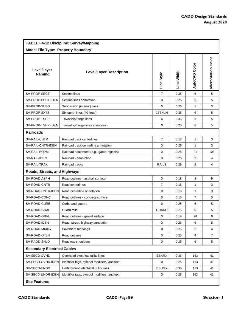
CADD - Page 89 Section I CADD Standards
CADD Design Standards
August 2020
TABLE I-4-12 Discipline: Survey/Mapping
Model File Type: Property Boundary
Level/Layer
Naming
Level/Layer Description
Lin
e S
tyle
Lin
e W
idth
Au
toC
AD
Co
lor
Mic
roS
tati
on
Co
lor
SV-PROP-SECT Section lines 7 0.35 6 5
SV-PROP-SECT-IDEN Section lines annotation 0 0.25 6 5
SV-PROP-SUBD Subdivision (interior) lines 0 0.25 1 3
SV-PROP-SXTS Sixteenth lines (40 lines) 16THLN 0.35 6 5
SV-PROP-TSHP Township/range lines 4 0.35 6 5
SV-PROP-TSHP-IDEN Township/range lines annotation 0 0.25 6 5
Railroads
SV-RAIL-CNTR Railroad track centerlines 7 0.18 1 3
SV-RAIL-CNTR-IDEN Railroad track centerline annotation 0 0.25 1 3
SV-RAIL-EQPM Railroad equipment (e.g., gates, signals) 0 0.25 91 106
SV-RAIL-IDEN Railroad - annotation 0 0.25 2 4
SV-RAIL-TRAK Railroad tracks RAILS 0.25 2 4
Roads, Streets, and Highways
SV-ROAD-ASPH Road outlines - asphalt surface 0 0.18 8 9
SV-ROAD-CNTR Road centerlines 7 0.18 1 3
SV-ROAD-CNTR-IDEN Road centerline annotation 0 0.18 1 3
SV-ROAD-CONC Road outlines - concrete surface 0 0.18 7 0
SV-ROAD-CURB Curbs and gutters 0 0.25 6 5
SV-ROAD-GRAL Guard rails GUARD 0.25 6 5
SV-ROAD-GRVL Road outlines - gravel surface 0 0.18 20 6
SV-ROAD-IDEN Road, street, highway annotation 0 0.25 6 5
SV-ROAD-MRKG Pavement markings 0 0.25 2 4
SV-ROAD-OTLN Road outlines 0 0.25 4 7
SV-RAOD-SHLD Roadway shoulders 0 0.25 6 5
Secondary Electrical Cables
SV-SECD-OVHD Overhead electrical utility lines ESARX 0.35 163 41
SV-SECD-OVHD-IDEN Identifier tags, symbol modifiers, and text 0 0.25 163 41
SV-SECD-UNDR Underground electrical utility lines ESUGX 0.35 163 41
SV-SECD-UNDR-IDEN Identifier tags, symbol modifiers, and text 0 0.25 163 41
Site Features
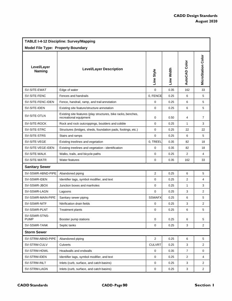
CADD - Page 90 Section I CADD Standards
CADD Design Standards
August 2020
TABLE I-4-12 Discipline: Survey/Mapping
Model File Type: Property Boundary
Level/Layer
Naming
Level/Layer Description
Lin
e S
tyle
Lin
e W
idth
Au
toC
AD
Co
lor
Mic
roS
tati
on
Co
lor
SV-SITE-EWAT Edge of water 0 0.35 162 33
SV-SITE-FENC Fences and handrails 0, FENCE 0.25 6 5
SV-SITE-FENC-IDEN Fence, handrail, ramp, and trail annotation 0 0.25 6 5
SV-SITE-IDEN Existing site feature/structure annotation 0 0.25 6 5
SV-SITE-OTLN Existing site features (play structures, bike racks, benches, recreational equipment
0
0.50
4
7
SV-SITE-ROCK Rock and rock outcroppings, boulders and cobble 0 0.25 1 3
SV-SITE-STRC Structures (bridges, sheds, foundation pads, footings, etc.) 0 0.25 22 22
SV-SITE-STRS Stairs and ramps 0 0.25 6 5
SV-SITE-VEGE Existing treelines and vegetation 0, TREEL 0.35 82 18
SV-SITE-VEGE-IDEN Existing treelines and vegetation - identification 0 0.35 82 18
SV-SITE-WALK Walks, trails, and bicycle paths 0 0.25 2 4
SV-SITE-WATR Water features 0 0.35 162 33
Sanitary Sewer
SV-SSWR-ABND-PIPE Abandoned piping 2 0.25 6 5
SV-SSWR-IDEN Identifier tags, symbol modifier, and text 0 0.25 2 4
SV-SSWR-JBOX Junction boxes and manholes 0 0.25 1 3
SV-SSWR-LAGN Lagoons 0 0.25 3 2
SV-SSWR-MAIN-PIPE Sanitary sewer piping SSWAFX 0.25 6 5
SV-SSWR-NITF Nitrification drain fields 0 0.25 3 2
SV-SSWR-PLNT Treatment plants 0 0.25 6 5
SV-SSWR-STNS- PUMP
Booster pump stations
0
0.25
6
5
SV-SSWR-TANK Septic tanks 0 0.25 3 2
Storm Sewer
SV-STRM-ABND-PIPE Abandoned piping 2 0.25 6 5
SV-STRM-CULV Culverts CULVRT 0.25 3 2
SV-STRM-HDWL Headwalls and endwalls 0 0.35 7 0
SV-STRM-IDEN Identifier tags, symbol modifier, and text 0 0.25 2 4
SV-STRM-INLT Inlets (curb, surface, and catch basins) 0 0.25 3 2
SV-STRM-LAGN Inlets (curb, surface, and catch basins) 0 0.25 3 2
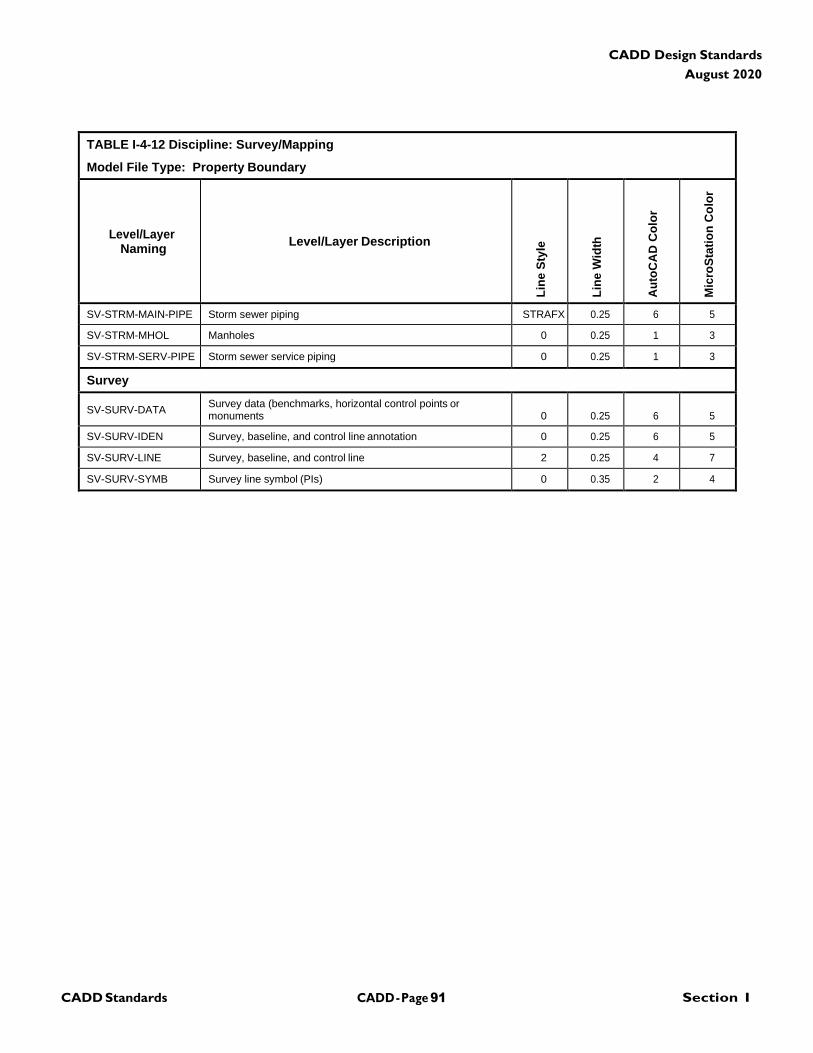
CADD - Page 91 Section I CADD Standards
CADD Design Standards
August 2020
TABLE I-4-12 Discipline: Survey/Mapping
Model File Type: Property Boundary
Level/Layer
Naming
Level/Layer Description
Lin
e S
tyle
Lin
e W
idth
Au
toC
AD
Co
lor
Mic
roS
tati
on
Co
lor
SV-STRM-MAIN-PIPE Storm sewer piping STRAFX 0.25 6 5
SV-STRM-MHOL Manholes 0 0.25 1 3
SV-STRM-SERV-PIPE Storm sewer service piping 0 0.25 1 3
Survey
SV-SURV-DATA Survey data (benchmarks, horizontal control points or monuments
0
0.25
6
5
SV-SURV-IDEN Survey, baseline, and control line annotation 0 0.25 6 5
SV-SURV-LINE Survey, baseline, and control line 2 0.25 4 7
SV-SURV-SYMB Survey line symbol (PIs) 0 0.35 2 4
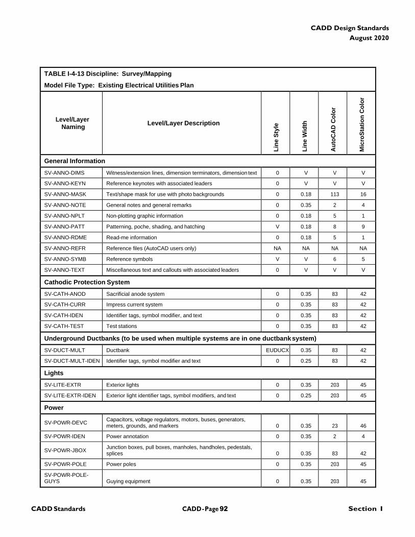
CADD - Page 92 Section I CADD Standards
CADD Design Standards
August 2020
TABLE I-4-13 Discipline: Survey/Mapping
Model File Type: Existing Electrical Utilities Plan
Level/Layer
Naming
Level/Layer Description
Lin
e S
tyle
Lin
e W
idth
Au
toC
AD
Co
lor
Mic
roS
tati
on
Co
lor
General Information
SV-ANNO-DIMS Witness/extension lines, dimension terminators, dimension text 0 V V V
SV-ANNO-KEYN Reference keynotes with associated leaders 0 V V V
SV-ANNO-MASK Text/shape mask for use with photo backgrounds 0 0.18 113 16
SV-ANNO-NOTE General notes and general remarks 0 0.35 2 4
SV-ANNO-NPLT Non-plotting graphic information 0 0.18 5 1
SV-ANNO-PATT Patterning, poche, shading, and hatching V 0.18 8 9
SV-ANNO-RDME Read-me information 0 0.18 5 1
SV-ANNO-REFR Reference files (AutoCAD users only) NA NA NA NA
SV-ANNO-SYMB Reference symbols V V 6 5
SV-ANNO-TEXT Miscellaneous text and callouts with associated leaders 0 V V V
Cathodic Protection System
SV-CATH-ANOD Sacrificial anode system 0 0.35 83 42
SV-CATH-CURR Impress current system 0 0.35 83 42
SV-CATH-IDEN Identifier tags, symbol modifier, and text 0 0.35 83 42
SV-CATH-TEST Test stations 0 0.35 83 42
Underground Ductbanks (to be used when multiple systems are in one ductbank system)
SV-DUCT-MULT Ductbank EUDUCX 0.35 83 42
SV-DUCT-MULT-IDEN Identifier tags, symbol modifier and text 0 0.25 83 42
Lights
SV-LITE-EXTR Exterior lights 0 0.35 203 45
SV-LITE-EXTR-IDEN Exterior light identifier tags, symbol modifiers, and text 0 0.25 203 45
Power
SV-POWR-DEVC Capacitors, voltage regulators, motors, buses, generators, meters, grounds, and markers
0
0.35
23
46
SV-POWR-IDEN Power annotation 0 0.35 2 4
SV-POWR-JBOX Junction boxes, pull boxes, manholes, handholes, pedestals, splices
0
0.35
83
42
SV-POWR-POLE Power poles 0 0.35 203 45
SV-POWR-POLE- GUYS
Guying equipment
0
0.35
203
45
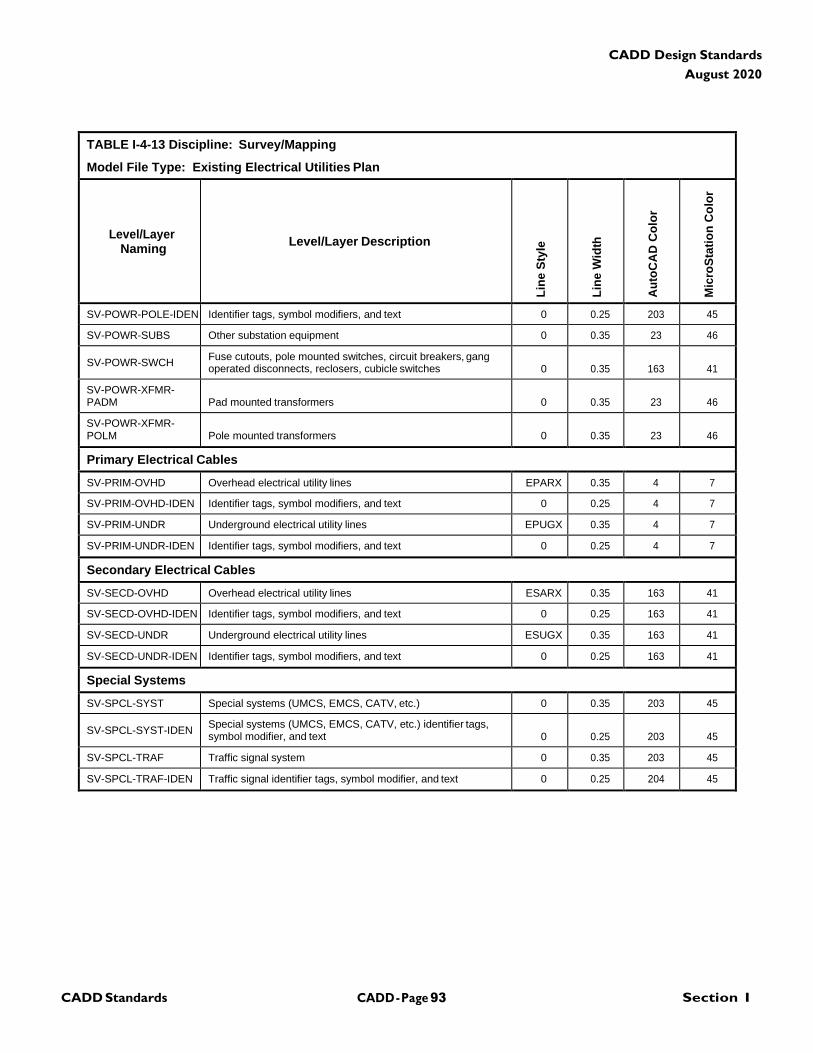
CADD - Page 93 Section I CADD Standards
CADD Design Standards
August 2020
TABLE I-4-13 Discipline: Survey/Mapping
Model File Type: Existing Electrical Utilities Plan
Level/Layer
Naming
Level/Layer Description
Lin
e S
tyle
Lin
e W
idth
Au
toC
AD
Co
lor
Mic
roS
tati
on
Co
lor
SV-POWR-POLE-IDEN Identifier tags, symbol modifiers, and text 0 0.25 203 45
SV-POWR-SUBS Other substation equipment 0 0.35 23 46
SV-POWR-SWCH Fuse cutouts, pole mounted switches, circuit breakers, gang operated disconnects, reclosers, cubicle switches
0
0.35
163
41
SV-POWR-XFMR- PADM
Pad mounted transformers
0
0.35
23
46
SV-POWR-XFMR- POLM
Pole mounted transformers
0
0.35
23
46
Primary Electrical Cables
SV-PRIM-OVHD Overhead electrical utility lines EPARX 0.35 4 7
SV-PRIM-OVHD-IDEN Identifier tags, symbol modifiers, and text 0 0.25 4 7
SV-PRIM-UNDR Underground electrical utility lines EPUGX 0.35 4 7
SV-PRIM-UNDR-IDEN Identifier tags, symbol modifiers, and text 0 0.25 4 7
Secondary Electrical Cables
SV-SECD-OVHD Overhead electrical utility lines ESARX 0.35 163 41
SV-SECD-OVHD-IDEN Identifier tags, symbol modifiers, and text 0 0.25 163 41
SV-SECD-UNDR Underground electrical utility lines ESUGX 0.35 163 41
SV-SECD-UNDR-IDEN Identifier tags, symbol modifiers, and text 0 0.25 163 41
Special Systems
SV-SPCL-SYST Special systems (UMCS, EMCS, CATV, etc.) 0 0.35 203 45
SV-SPCL-SYST-IDEN Special systems (UMCS, EMCS, CATV, etc.) identifier tags, symbol modifier, and text
0
0.25
203
45
SV-SPCL-TRAF Traffic signal system 0 0.35 203 45
SV-SPCL-TRAF-IDEN Traffic signal identifier tags, symbol modifier, and text 0 0.25 204 45
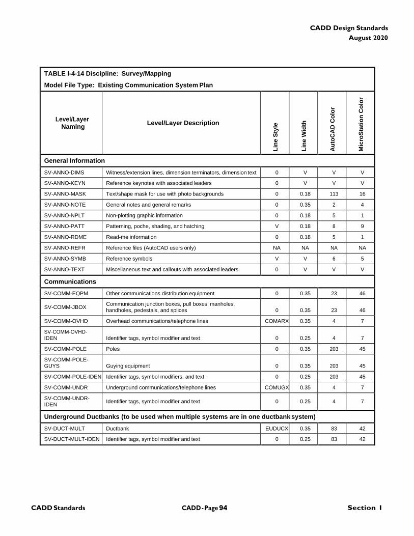
CADD - Page 94 Section I CADD Standards
CADD Design Standards
August 2020
TABLE I-4-14 Discipline: Survey/Mapping
Model File Type: Existing Communication System Plan
Level/Layer
Naming
Level/Layer Description
Lin
e S
tyle
Lin
e W
idth
Au
toC
AD
Co
lor
Mic
roS
tati
on
Co
lor
General Information
SV-ANNO-DIMS Witness/extension lines, dimension terminators, dimension text 0 V V V
SV-ANNO-KEYN Reference keynotes with associated leaders 0 V V V
SV-ANNO-MASK Text/shape mask for use with photo backgrounds 0 0.18 113 16
SV-ANNO-NOTE General notes and general remarks 0 0.35 2 4
SV-ANNO-NPLT Non-plotting graphic information 0 0.18 5 1
SV-ANNO-PATT Patterning, poche, shading, and hatching V 0.18 8 9
SV-ANNO-RDME Read-me information 0 0.18 5 1
SV-ANNO-REFR Reference files (AutoCAD users only) NA NA NA NA
SV-ANNO-SYMB Reference symbols V V 6 5
SV-ANNO-TEXT Miscellaneous text and callouts with associated leaders 0 V V V
Communications
SV-COMM-EQPM Other communications distribution equipment 0 0.35 23 46
SV-COMM-JBOX Communication junction boxes, pull boxes, manholes, handholes, pedestals, and splices
0
0.35
23
46
SV-COMM-OVHD Overhead communications/telephone lines COMARX 0.35 4 7
SV-COMM-OVHD- IDEN
Identifier tags, symbol modifier and text
0
0.25
4
7
SV-COMM-POLE Poles 0 0.35 203 45
SV-COMM-POLE- GUYS
Guying equipment
0
0.35
203
45
SV-COMM-POLE-IDEN Identifier tags, symbol modifiers, and text 0 0.25 203 45
SV-COMM-UNDR Underground communications/telephone lines COMUGX 0.35 4 7
SV-COMM-UNDR- IDEN
Identifier tags, symbol modifier and text
0
0.25
4
7
Underground Ductbanks (to be used when multiple systems are in one ductbank system)
SV-DUCT-MULT Ductbank EUDUCX 0.35 83 42
SV-DUCT-MULT-IDEN Identifier tags, symbol modifier and text 0 0.25 83 42
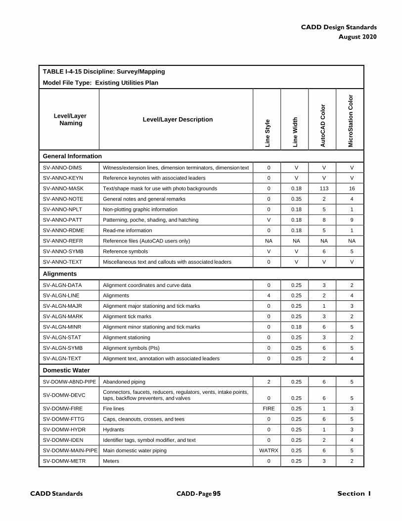
CADD - Page 95 Section I CADD Standards
CADD Design Standards
August 2020
TABLE I-4-15 Discipline: Survey/Mapping
Model File Type: Existing Utilities Plan
Level/Layer
Naming
Level/Layer Description
Lin
e S
tyle
Lin
e W
idth
Au
toC
AD
Co
lor
Mic
roS
tati
on
Co
lor
General Information
SV-ANNO-DIMS Witness/extension lines, dimension terminators, dimension text 0 V V V
SV-ANNO-KEYN Reference keynotes with associated leaders 0 V V V
SV-ANNO-MASK Text/shape mask for use with photo backgrounds 0 0.18 113 16
SV-ANNO-NOTE General notes and general remarks 0 0.35 2 4
SV-ANNO-NPLT Non-plotting graphic information 0 0.18 5 1
SV-ANNO-PATT Patterning, poche, shading, and hatching V 0.18 8 9
SV-ANNO-RDME Read-me information 0 0.18 5 1
SV-ANNO-REFR Reference files (AutoCAD users only) NA NA NA NA
SV-ANNO-SYMB Reference symbols V V 6 5
SV-ANNO-TEXT Miscellaneous text and callouts with associated leaders 0 V V V
Alignments
SV-ALGN-DATA Alignment coordinates and curve data 0 0.25 3 2
SV-ALGN-LINE Alignments 4 0.25 2 4
SV-ALGN-MAJR Alignment major stationing and tick marks 0 0.25 1 3
SV-ALGN-MARK Alignment tick marks 0 0.25 3 2
SV-ALGN-MINR Alignment minor stationing and tick marks 0 0.18 6 5
SV-ALGN-STAT Alignment stationing 0 0.25 3 2
SV-ALGN-SYMB Alignment symbols (PIs) 0 0.25 6 5
SV-ALGN-TEXT Alignment text, annotation with associated leaders 0 0.25 2 4
Domestic Water
SV-DOMW-ABND-PIPE Abandoned piping 2 0.25 6 5
SV-DOMW-DEVC Connectors, faucets, reducers, regulators, vents, intake points, taps, backflow preventers, and valves
0
0.25
6
5
SV-DOMW-FIRE Fire lines FIRE 0.25 1 3
SV-DOMW-FTTG Caps, cleanouts, crosses, and tees 0 0.25 6 5
SV-DOMW-HYDR Hydrants 0 0.25 1 3
SV-DOMW-IDEN Identifier tags, symbol modifier, and text 0 0.25 2 4
SV-DOMW-MAIN-PIPE Main domestic water piping WATRX 0.25 6 5
SV-DOMW-METR Meters 0 0.25 3 2
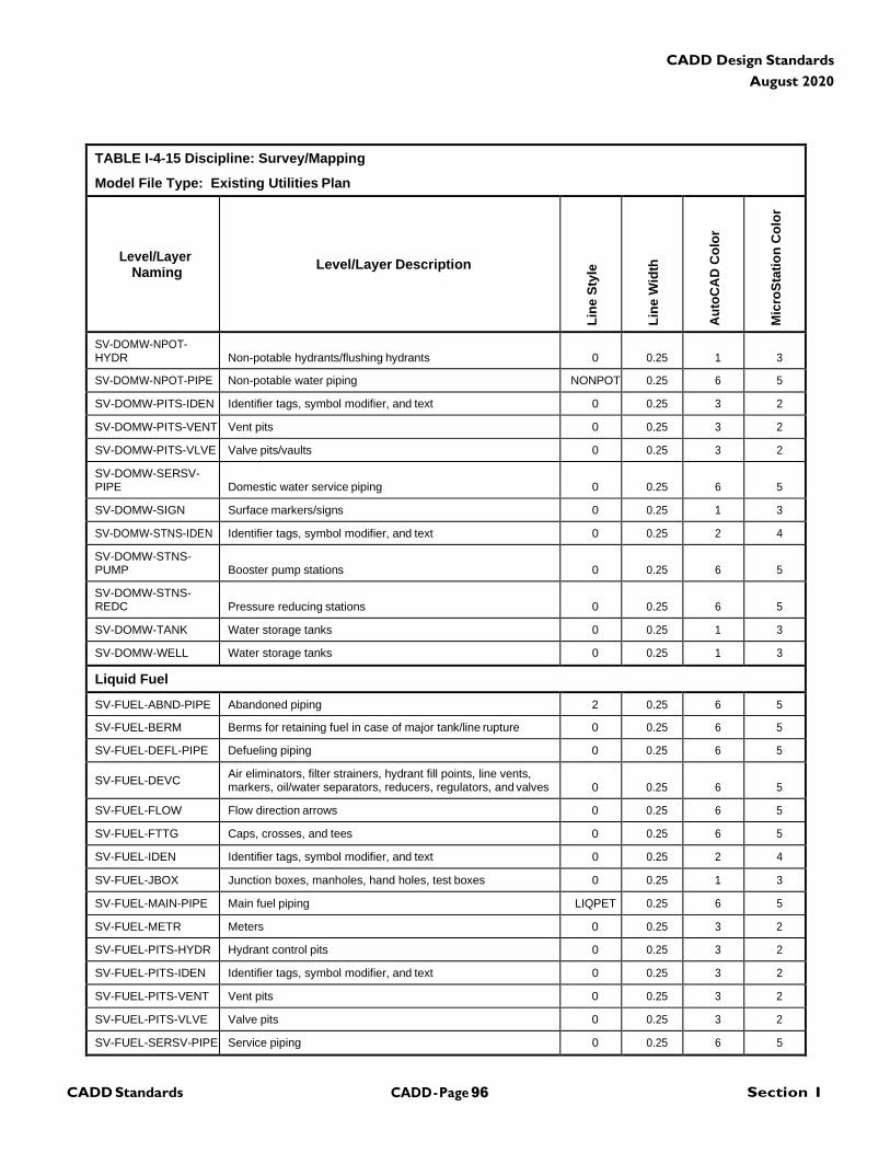
CADD - Page 96 Section I CADD Standards
CADD Design Standards
August 2020
TABLE I-4-15 Discipline: Survey/Mapping
Model File Type: Existing Utilities Plan
Level/Layer
Naming
Level/Layer Description
Lin
e S
tyle
Lin
e W
idth
Au
toC
AD
Co
lor
Mic
roS
tati
on
Co
lor
SV-DOMW-NPOT- HYDR
Non-potable hydrants/flushing hydrants
0
0.25
1
3
SV-DOMW-NPOT-PIPE Non-potable water piping NONPOT 0.25 6 5
SV-DOMW-PITS-IDEN Identifier tags, symbol modifier, and text 0 0.25 3 2
SV-DOMW-PITS-VENT Vent pits 0 0.25 3 2
SV-DOMW-PITS-VLVE Valve pits/vaults 0 0.25 3 2
SV-DOMW-SERSV- PIPE
Domestic water service piping
0
0.25
6
5
SV-DOMW-SIGN Surface markers/signs 0 0.25 1 3
SV-DOMW-STNS-IDEN Identifier tags, symbol modifier, and text 0 0.25 2 4
SV-DOMW-STNS- PUMP
Booster pump stations
0
0.25
6
5
SV-DOMW-STNS- REDC
Pressure reducing stations
0
0.25
6
5
SV-DOMW-TANK Water storage tanks 0 0.25 1 3
SV-DOMW-WELL Water storage tanks 0 0.25 1 3
Liquid Fuel
SV-FUEL-ABND-PIPE Abandoned piping 2 0.25 6 5
SV-FUEL-BERM Berms for retaining fuel in case of major tank/line rupture 0 0.25 6 5
SV-FUEL-DEFL-PIPE Defueling piping 0 0.25 6 5
SV-FUEL-DEVC Air eliminators, filter strainers, hydrant fill points, line vents, markers, oil/water separators, reducers, regulators, and valves
0
0.25
6
5
SV-FUEL-FLOW Flow direction arrows 0 0.25 6 5
SV-FUEL-FTTG Caps, crosses, and tees 0 0.25 6 5
SV-FUEL-IDEN Identifier tags, symbol modifier, and text 0 0.25 2 4
SV-FUEL-JBOX Junction boxes, manholes, hand holes, test boxes 0 0.25 1 3
SV-FUEL-MAIN-PIPE Main fuel piping LIQPET 0.25 6 5
SV-FUEL-METR Meters 0 0.25 3 2
SV-FUEL-PITS-HYDR Hydrant control pits 0 0.25 3 2
SV-FUEL-PITS-IDEN Identifier tags, symbol modifier, and text 0 0.25 3 2
SV-FUEL-PITS-VENT Vent pits 0 0.25 3 2
SV-FUEL-PITS-VLVE Valve pits 0 0.25 3 2
SV-FUEL-SERSV-PIPE Service piping 0 0.25 6 5
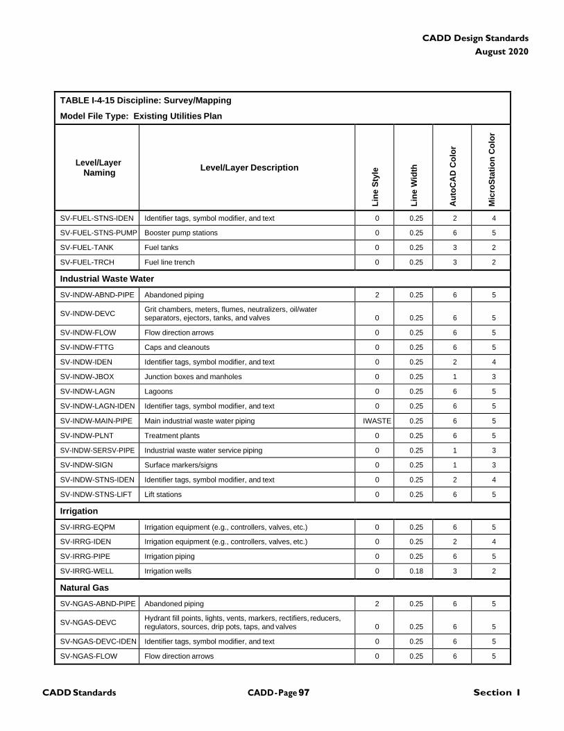
CADD - Page 97 Section I CADD Standards
CADD Design Standards
August 2020
TABLE I-4-15 Discipline: Survey/Mapping
Model File Type: Existing Utilities Plan
Level/Layer
Naming
Level/Layer Description
Lin
e S
tyle
Lin
e W
idth
Au
toC
AD
Co
lor
Mic
roS
tati
on
Co
lor
SV-FUEL-STNS-IDEN Identifier tags, symbol modifier, and text 0 0.25 2 4
SV-FUEL-STNS-PUMP Booster pump stations 0 0.25 6 5
SV-FUEL-TANK Fuel tanks 0 0.25 3 2
SV-FUEL-TRCH Fuel line trench 0 0.25 3 2
Industrial Waste Water
SV-INDW-ABND-PIPE Abandoned piping 2 0.25 6 5
SV-INDW-DEVC Grit chambers, meters, flumes, neutralizers, oil/water separators, ejectors, tanks, and valves
0
0.25
6
5
SV-INDW-FLOW Flow direction arrows 0 0.25 6 5
SV-INDW-FTTG Caps and cleanouts 0 0.25 6 5
SV-INDW-IDEN Identifier tags, symbol modifier, and text 0 0.25 2 4
SV-INDW-JBOX Junction boxes and manholes 0 0.25 1 3
SV-INDW-LAGN Lagoons 0 0.25 6 5
SV-INDW-LAGN-IDEN Identifier tags, symbol modifier, and text 0 0.25 6 5
SV-INDW-MAIN-PIPE Main industrial waste water piping IWASTE 0.25 6 5
SV-INDW-PLNT Treatment plants 0 0.25 6 5
SV-INDW-SERSV-PIPE Industrial waste water service piping 0 0.25 1 3
SV-INDW-SIGN Surface markers/signs 0 0.25 1 3
SV-INDW-STNS-IDEN Identifier tags, symbol modifier, and text 0 0.25 2 4
SV-INDW-STNS-LIFT Lift stations 0 0.25 6 5
Irrigation
SV-IRRG-EQPM Irrigation equipment (e.g., controllers, valves, etc.) 0 0.25 6 5
SV-IRRG-IDEN Irrigation equipment (e.g., controllers, valves, etc.) 0 0.25 2 4
SV-IRRG-PIPE Irrigation piping 0 0.25 6 5
SV-IRRG-WELL Irrigation wells 0 0.18 3 2
Natural Gas
SV-NGAS-ABND-PIPE Abandoned piping 2 0.25 6 5
SV-NGAS-DEVC Hydrant fill points, lights, vents, markers, rectifiers, reducers, regulators, sources, drip pots, taps, and valves
0
0.25
6
5
SV-NGAS-DEVC-IDEN Identifier tags, symbol modifier, and text 0 0.25 6 5
SV-NGAS-FLOW Flow direction arrows 0 0.25 6 5
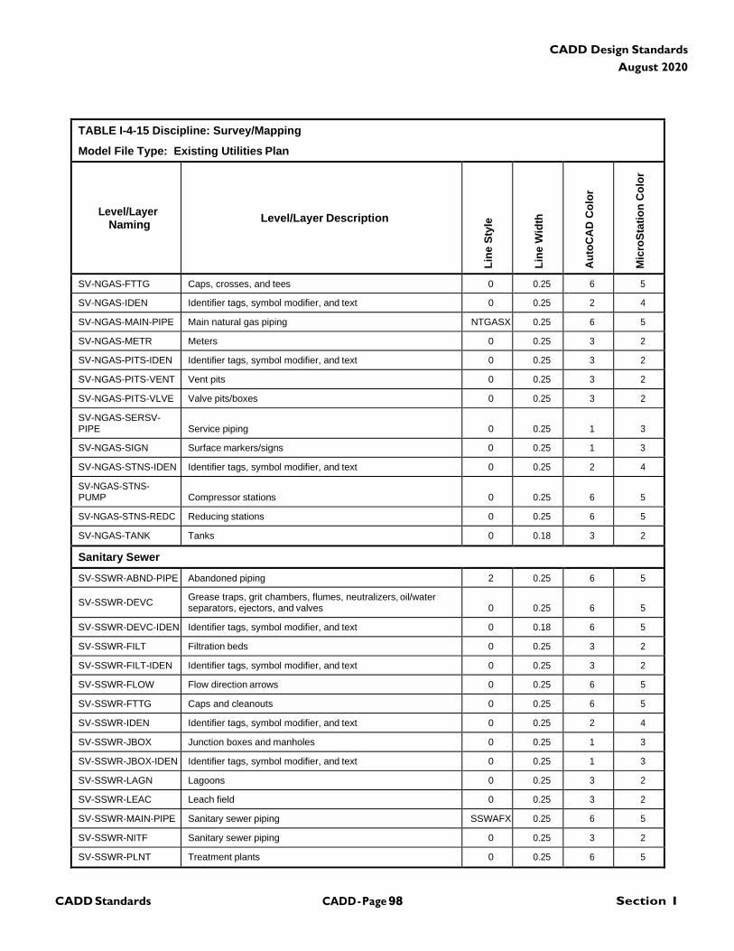
CADD - Page 98 Section I CADD Standards
CADD Design Standards
August 2020
TABLE I-4-15 Discipline: Survey/Mapping
Model File Type: Existing Utilities Plan
Level/Layer
Naming
Level/Layer Description
Lin
e S
tyle
Lin
e W
idth
Au
toC
AD
Co
lor
Mic
roS
tati
on
Co
lor
SV-NGAS-FTTG Caps, crosses, and tees 0 0.25 6 5
SV-NGAS-IDEN Identifier tags, symbol modifier, and text 0 0.25 2 4
SV-NGAS-MAIN-PIPE Main natural gas piping NTGASX 0.25 6 5
SV-NGAS-METR Meters 0 0.25 3 2
SV-NGAS-PITS-IDEN Identifier tags, symbol modifier, and text 0 0.25 3 2
SV-NGAS-PITS-VENT Vent pits 0 0.25 3 2
SV-NGAS-PITS-VLVE Valve pits/boxes 0 0.25 3 2
SV-NGAS-SERSV- PIPE
Service piping
0
0.25
1
3
SV-NGAS-SIGN Surface markers/signs 0 0.25 1 3
SV-NGAS-STNS-IDEN Identifier tags, symbol modifier, and text 0 0.25 2 4
SV-NGAS-STNS- PUMP
Compressor stations
0
0.25
6
5
SV-NGAS-STNS-REDC Reducing stations 0 0.25 6 5
SV-NGAS-TANK Tanks 0 0.18 3 2
Sanitary Sewer
SV-SSWR-ABND-PIPE Abandoned piping 2 0.25 6 5
SV-SSWR-DEVC Grease traps, grit chambers, flumes, neutralizers, oil/water separators, ejectors, and valves
0
0.25
6
5
SV-SSWR-DEVC-IDEN Identifier tags, symbol modifier, and text 0 0.18 6 5
SV-SSWR-FILT Filtration beds 0 0.25 3 2
SV-SSWR-FILT-IDEN Identifier tags, symbol modifier, and text 0 0.25 3 2
SV-SSWR-FLOW Flow direction arrows 0 0.25 6 5
SV-SSWR-FTTG Caps and cleanouts 0 0.25 6 5
SV-SSWR-IDEN Identifier tags, symbol modifier, and text 0 0.25 2 4
SV-SSWR-JBOX Junction boxes and manholes 0 0.25 1 3
SV-SSWR-JBOX-IDEN Identifier tags, symbol modifier, and text 0 0.25 1 3
SV-SSWR-LAGN Lagoons 0 0.25 3 2
SV-SSWR-LEAC Leach field 0 0.25 3 2
SV-SSWR-MAIN-PIPE Sanitary sewer piping SSWAFX 0.25 6 5
SV-SSWR-NITF Sanitary sewer piping 0 0.25 3 2
SV-SSWR-PLNT Treatment plants 0 0.25 6 5
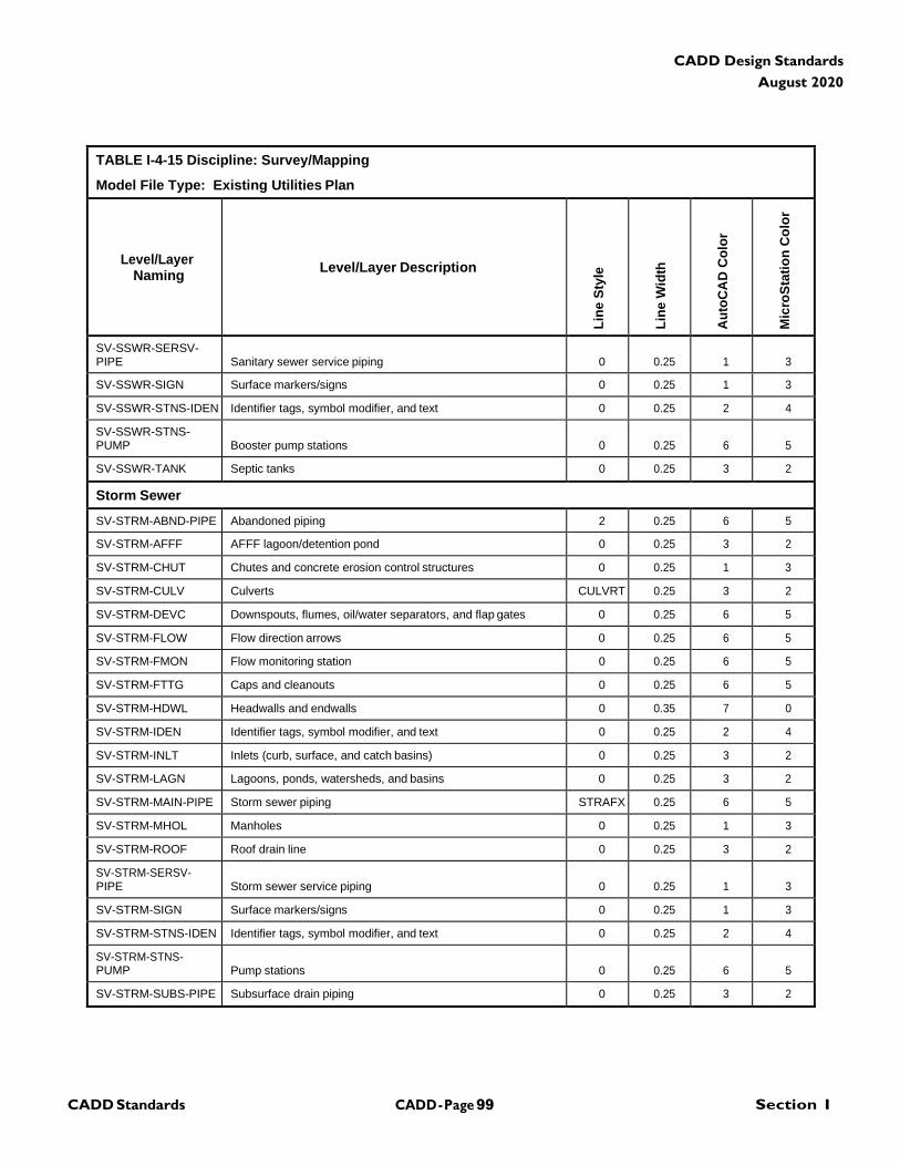
CADD - Page 99 Section I CADD Standards
CADD Design Standards
August 2020
TABLE I-4-15 Discipline: Survey/Mapping
Model File Type: Existing Utilities Plan
Level/Layer
Naming
Level/Layer Description
Lin
e S
tyle
Lin
e W
idth
Au
toC
AD
Co
lor
Mic
roS
tati
on
Co
lor
SV-SSWR-SERSV- PIPE
Sanitary sewer service piping
0
0.25
1
3
SV-SSWR-SIGN Surface markers/signs 0 0.25 1 3
SV-SSWR-STNS-IDEN Identifier tags, symbol modifier, and text 0 0.25 2 4
SV-SSWR-STNS- PUMP
Booster pump stations
0
0.25
6
5
SV-SSWR-TANK Septic tanks 0 0.25 3 2
Storm Sewer
SV-STRM-ABND-PIPE Abandoned piping 2 0.25 6 5
SV-STRM-AFFF AFFF lagoon/detention pond 0 0.25 3 2
SV-STRM-CHUT Chutes and concrete erosion control structures 0 0.25 1 3
SV-STRM-CULV Culverts CULVRT 0.25 3 2
SV-STRM-DEVC Downspouts, flumes, oil/water separators, and flap gates 0 0.25 6 5
SV-STRM-FLOW Flow direction arrows 0 0.25 6 5
SV-STRM-FMON Flow monitoring station 0 0.25 6 5
SV-STRM-FTTG Caps and cleanouts 0 0.25 6 5
SV-STRM-HDWL Headwalls and endwalls 0 0.35 7 0
SV-STRM-IDEN Identifier tags, symbol modifier, and text 0 0.25 2 4
SV-STRM-INLT Inlets (curb, surface, and catch basins) 0 0.25 3 2
SV-STRM-LAGN Lagoons, ponds, watersheds, and basins 0 0.25 3 2
SV-STRM-MAIN-PIPE Storm sewer piping STRAFX 0.25 6 5
SV-STRM-MHOL Manholes 0 0.25 1 3
SV-STRM-ROOF Roof drain line 0 0.25 3 2
SV-STRM-SERSV- PIPE
Storm sewer service piping
0
0.25
1
3
SV-STRM-SIGN Surface markers/signs 0 0.25 1 3
SV-STRM-STNS-IDEN Identifier tags, symbol modifier, and text 0 0.25 2 4
SV-STRM-STNS- PUMP
Pump stations
0
0.25
6
5
SV-STRM-SUBS-PIPE Subsurface drain piping 0 0.25 3 2
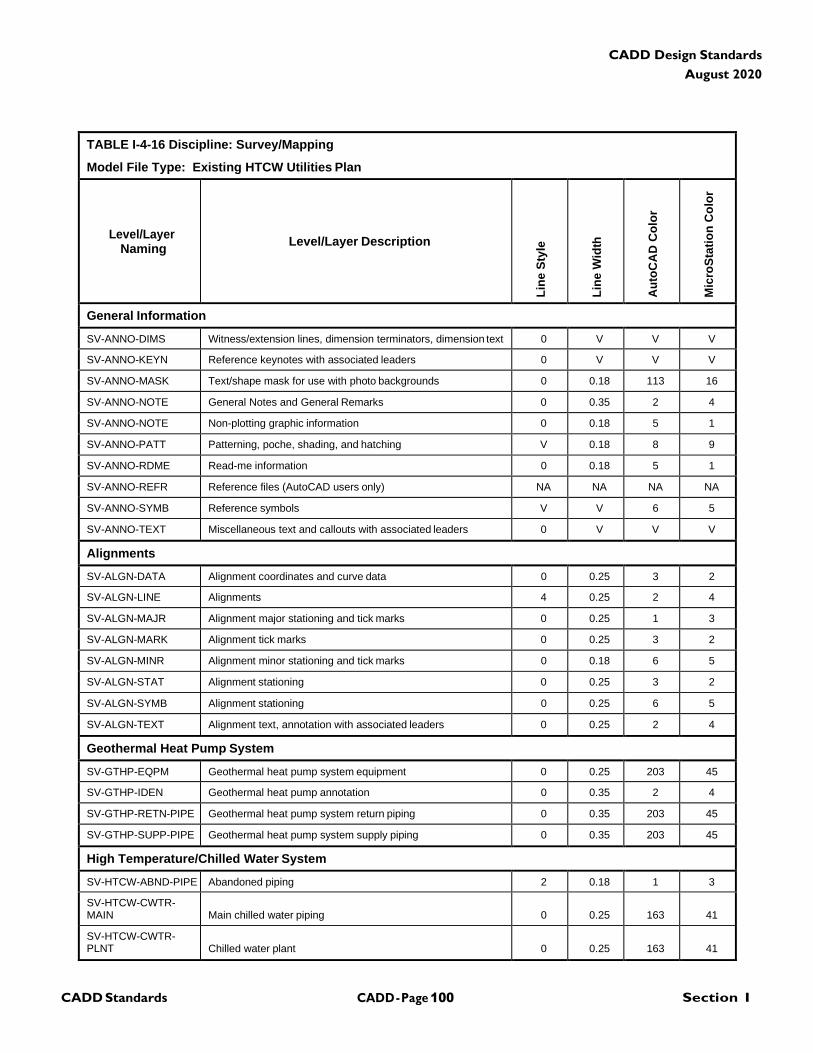
CADD - Page 100 Section I CADD Standards
CADD Design Standards
August 2020
TABLE I-4-16 Discipline: Survey/Mapping
Model File Type: Existing HTCW Utilities Plan
Level/Layer
Naming
Level/Layer Description
Lin
e S
tyle
Lin
e W
idth
Au
toC
AD
Co
lor
Mic
roS
tati
on
Co
lor
General Information
SV-ANNO-DIMS Witness/extension lines, dimension terminators, dimension text 0 V V V
SV-ANNO-KEYN Reference keynotes with associated leaders 0 V V V
SV-ANNO-MASK Text/shape mask for use with photo backgrounds 0 0.18 113 16
SV-ANNO-NOTE General Notes and General Remarks 0 0.35 2 4
SV-ANNO-NOTE Non-plotting graphic information 0 0.18 5 1
SV-ANNO-PATT Patterning, poche, shading, and hatching V 0.18 8 9
SV-ANNO-RDME Read-me information 0 0.18 5 1
SV-ANNO-REFR Reference files (AutoCAD users only) NA NA NA NA
SV-ANNO-SYMB Reference symbols V V 6 5
SV-ANNO-TEXT Miscellaneous text and callouts with associated leaders 0 V V V
Alignments
SV-ALGN-DATA Alignment coordinates and curve data 0 0.25 3 2
SV-ALGN-LINE Alignments 4 0.25 2 4
SV-ALGN-MAJR Alignment major stationing and tick marks 0 0.25 1 3
SV-ALGN-MARK Alignment tick marks 0 0.25 3 2
SV-ALGN-MINR Alignment minor stationing and tick marks 0 0.18 6 5
SV-ALGN-STAT Alignment stationing 0 0.25 3 2
SV-ALGN-SYMB Alignment stationing 0 0.25 6 5
SV-ALGN-TEXT Alignment text, annotation with associated leaders 0 0.25 2 4
Geothermal Heat Pump System
SV-GTHP-EQPM Geothermal heat pump system equipment 0 0.25 203 45
SV-GTHP-IDEN Geothermal heat pump annotation 0 0.35 2 4
SV-GTHP-RETN-PIPE Geothermal heat pump system return piping 0 0.35 203 45
SV-GTHP-SUPP-PIPE Geothermal heat pump system supply piping 0 0.35 203 45
High Temperature/Chilled Water System
SV-HTCW-ABND-PIPE Abandoned piping 2 0.18 1 3
SV-HTCW-CWTR- MAIN
Main chilled water piping
0
0.25
163
41
SV-HTCW-CWTR- PLNT
Chilled water plant
0
0.25
163
41
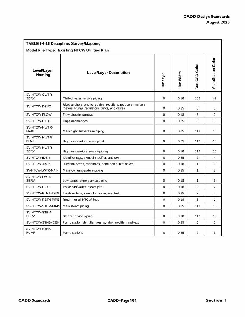
CADD - Page 101 Section I CADD Standards
CADD Design Standards
August 2020
TABLE I-4-16 Discipline: Survey/Mapping
Model File Type: Existing HTCW Utilities Plan
Level/Layer
Naming
Level/Layer Description
Lin
e S
tyle
Lin
e W
idth
Au
toC
AD
Co
lor
Mic
roS
tati
on
Co
lor
SV-HTCW-CWTR- SERV
Chilled water service piping
0
0.18
163
41
SV-HTCW-DEVC Rigid anchors, anchor guides, rectifiers, reducers, markers, meters, Pump, regulators, tanks, and valves
0
0.25
6
5
SV-HTCW-FLOW Flow direction arrows 0 0.18 3 2
SV-HTCW-FTTG Caps and flanges 0 0.25 6 5
SV-HTCW-HWTR- MAIN
Main high temperature piping
0
0.25
113
16
SV-HTCW-HWTR- PLNT
High temperature water plant
0
0.25
113
16
SV-HTCW-HWTR- SERV
High temperature service piping
0
0.18
113
16
SV-HTCW-IDEN Identifier tags, symbol modifier, and text 0 0.25 2 4
SV-HTCW-JBOX Junction boxes, manholes, hand holes, test boxes 0 0.18 1 3
SV-HTCW-LWTR-MAIN Main low temperature piping 0 0.25 1 3
SV-HTCW-LWTR- SERV
Low temperature service piping
0
0.18
1
3
SV-HTCW-PITS Valve pits/vaults, steam pits 0 0.18 3 2
SV-HTCW-PLNT-IDEN Identifier tags, symbol modifier, and text 0 0.25 2 4
SV-HTCW-RETN-PIPE Return for all HTCW lines 0 0.18 5 1
SV-HTCW-STEM-MAIN Main steam piping 0 0.25 113 16
SV-HTCW-STEM- SERV
Steam service piping
0
0.18
113
16
SV-HTCW-STNS-IDEN Pump station identifier tags, symbol modifier, and text 0 0.25 6 5
SV-HTCW-STNS- PUMP
Pump stations
0
0.25
6
5

CADD - Page 102 Section I CADD Standards
CADD Design Standards
August 2020
TABLE I-4-17 Discipline: Survey/Mapping
Model File Type: Existing Airfield Lighting Plan
Level/Layer
Naming
Level/Layer Description
Lin
e S
tyle
Lin
e W
idth
Au
toC
AD
Co
lor
Mic
roS
tati
on
Co
lor
General Information
SV-ANNO-DIMS Witness/extension lines, dimension terminators, dimension text 0 V V V
SV-ANNO-KEYN Reference keynotes with associated leaders 0 V V V
SV-ANNO-MASK Text/shape mask for use with photo backgrounds 0 0.18 113 16
SV-ANNO-NOTE General notes and general remarks 0 0.35 2 4
SV-ANNO-NPLT Non-plotting graphic information 0 0.18 5 1
SV-ANNO-PATT Patterning, poche, shading, and hatching V 0.18 8 9
SV-ANNO-RDME Read-me information 0 0.18 5 1
SV-ANNO-REFR Reference files (AutoCAD users only) NA NA NA NA
SV-ANNO-SYMB Reference symbols V V 6 5
SV-ANNO-TEXT Miscellaneous text and callouts with associated leaders 0 V V V
Airfield
SV-AFLD-BCNS-IDEN Identifier tags, symbol modifiers, and text 0 0.25 203 45
SV-AFLD-BCNS-MISC Miscellaneous navaids - windcones and beacons 0 0.35 203 45
SV-AFLD-BCNS-STRB Strobe beacons 0 0.35 203 45
SV-AFLD-CIRC-CTRL Control and monitoring circuits 0 0.35 163 41
SV-AFLD-CIRC-IDEN Circuit identifier tags, symbol modifier, and text 0 0.25 2 4
SV-AFLD-CIRC-MULT Multiple circuits 0 0.35 23 46
SV-AFLD-CIRC-SERS Series circuits 0 0.35 203 45
SV-AFLD-DEVC Capacitors, voltage regulators, motors, buses, generators, meters, grounds, and markers
0
0.35
23
46
SV-AFLD-DUCT Ductbanks EUDUCX 0.25 83 42
SV-AFLD-IDEN Airfield annotation 0 0.35 2 4
SV-AFLD-JBOX Junction boxes, pull boxes, manholes, handholes, pedestals, splices
0
0.35
23
46
SV-AFLD-LITE-APPR Approach lights 0 0.35 203 45
SV-AFLD-LITE-DIST Distance and arresting gear markers 0 0.35 203 45
SV-AFLD-LITE-LANE Hoverlane, taxilane, and helipad lights 0 0.35 203 45
SV-AFLD-LITE-OBST Obstruction lights 0 0.35 203 45
SV-AFLD-LITE-RUNW Runway lights 0 0.35 203 45
SV-AFLD-LITE-SIGN Taxiway guidance signs 0 0.35 203 45
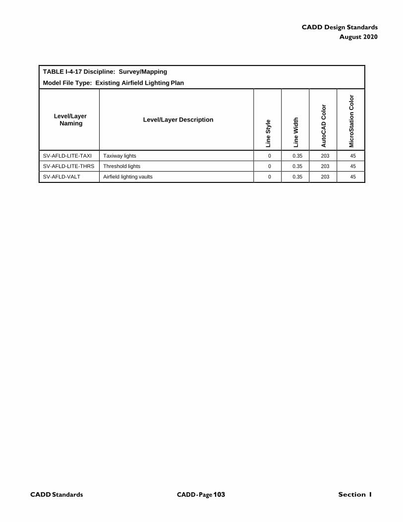
CADD - Page 103 Section I CADD Standards
CADD Design Standards
August 2020
TABLE I-4-17 Discipline: Survey/Mapping
Model File Type: Existing Airfield Lighting Plan
Level/Layer
Naming
Level/Layer Description
Lin
e S
tyle
Lin
e W
idth
Au
toC
AD
Co
lor
Mic
roS
tati
on
Co
lor
SV-AFLD-LITE-TAXI Taxiway lights 0 0.35 203 45
SV-AFLD-LITE-THRS Threshold lights 0 0.35 203 45
SV-AFLD-VALT Airfield lighting vaults 0 0.35 203 45
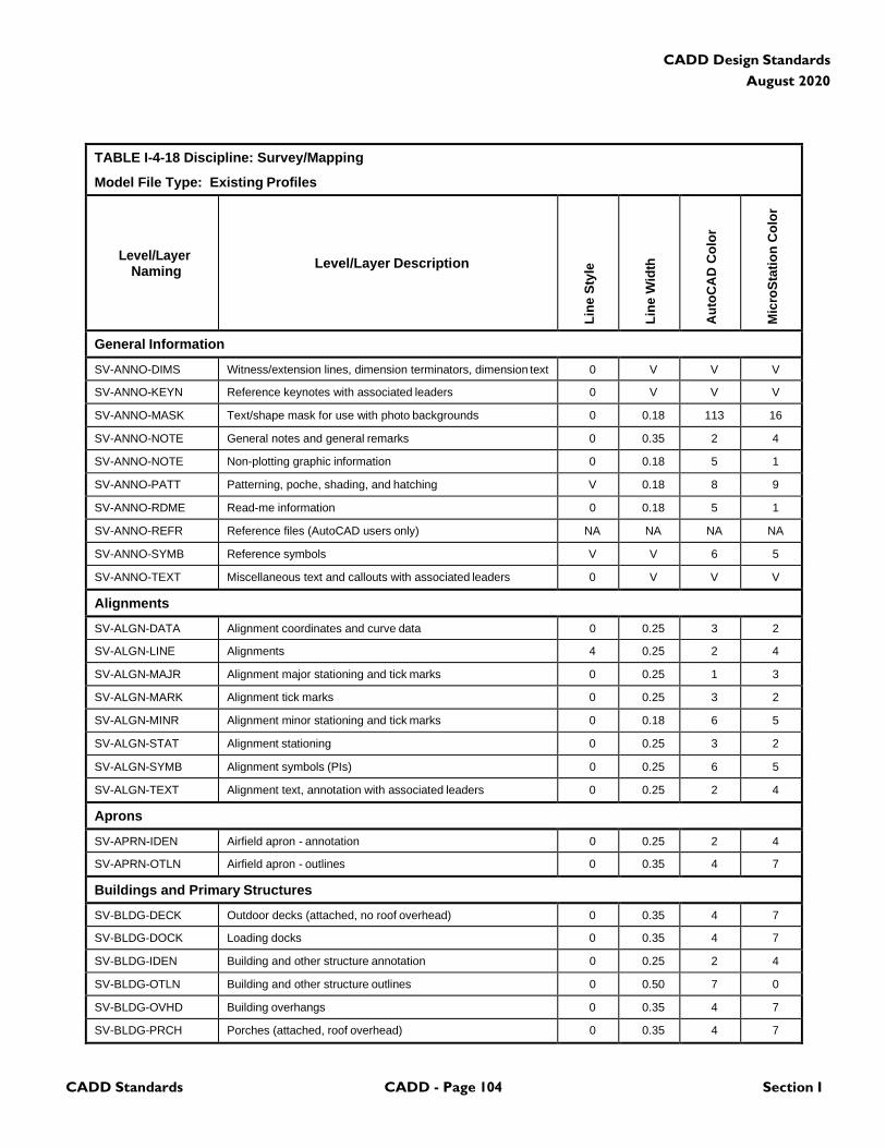
CADD Standards CADD - Page 104 Section I
CADD Design Standards
August 2020
TABLE I-4-18 Discipline: Survey/Mapping
Model File Type: Existing Profiles
Level/Layer
Naming
Level/Layer Description
Lin
e S
tyle
Lin
e W
idth
Au
toC
AD
Co
lor
Mic
roS
tati
on
Co
lor
General Information
SV-ANNO-DIMS Witness/extension lines, dimension terminators, dimension text 0 V V V
SV-ANNO-KEYN Reference keynotes with associated leaders 0 V V V
SV-ANNO-MASK Text/shape mask for use with photo backgrounds 0 0.18 113 16
SV-ANNO-NOTE General notes and general remarks 0 0.35 2 4
SV-ANNO-NOTE Non-plotting graphic information 0 0.18 5 1
SV-ANNO-PATT Patterning, poche, shading, and hatching V 0.18 8 9
SV-ANNO-RDME Read-me information 0 0.18 5 1
SV-ANNO-REFR Reference files (AutoCAD users only) NA NA NA NA
SV-ANNO-SYMB Reference symbols V V 6 5
SV-ANNO-TEXT Miscellaneous text and callouts with associated leaders 0 V V V
Alignments
SV-ALGN-DATA Alignment coordinates and curve data 0 0.25 3 2
SV-ALGN-LINE Alignments 4 0.25 2 4
SV-ALGN-MAJR Alignment major stationing and tick marks 0 0.25 1 3
SV-ALGN-MARK Alignment tick marks 0 0.25 3 2
SV-ALGN-MINR Alignment minor stationing and tick marks 0 0.18 6 5
SV-ALGN-STAT Alignment stationing 0 0.25 3 2
SV-ALGN-SYMB Alignment symbols (PIs) 0 0.25 6 5
SV-ALGN-TEXT Alignment text, annotation with associated leaders 0 0.25 2 4
Aprons
SV-APRN-IDEN Airfield apron - annotation 0 0.25 2 4
SV-APRN-OTLN Airfield apron - outlines 0 0.35 4 7
Buildings and Primary Structures
SV-BLDG-DECK Outdoor decks (attached, no roof overhead) 0 0.35 4 7
SV-BLDG-DOCK Loading docks 0 0.35 4 7
SV-BLDG-IDEN Building and other structure annotation 0 0.25 2 4
SV-BLDG-OTLN Building and other structure outlines 0 0.50 7 0
SV-BLDG-OVHD Building overhangs 0 0.35 4 7
SV-BLDG-PRCH Porches (attached, roof overhead)
0 0.35 4 7
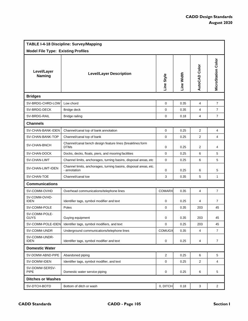
CADD Standards CADD - Page 105 Section I
CADD Design Standards
August 2020
TABLE I-4-18 Discipline: Survey/Mapping
Model File Type: Existing Profiles
Level/Layer
Naming
Level/Layer Description
Lin
e S
tyle
Lin
e W
idth
Au
toC
AD
Co
lor
Mic
roS
tati
on
Co
lor
Bridges
SV-BRDG-CHRD-LOW Low chord 0 0.35 4 7
SV-BRDG-DECK Bridge deck 0 0.35 4 7
SV-BRDG-RAIL Bridge railing 0 0.18 4 7
Channels
SV-CHAN-BANK-IDEN Channel/canal top of bank annotation 0 0.25 2 4
SV-CHAN-BANK-TOP Channel/canal top of bank 0 0.25 2 4
SV-CHAN-BNCH Channel/canal bench design feature lines (breaklines form DTMs
0
0.25
2
4
SV-CHAN-DOCK Docks, decks, floats, piers, and mooring facilities 0 0.25 6 5
SV-CHAN-LIMT Channel limits, anchorages, turning basins, disposal areas, etc 0 0.25 6 5
SV-CHAN-LIMT-IDEN Channel limits, anchorages, turning basins, disposal areas, etc. - annotation
0
0.25
6
5
SV-CHAN-TOE Channel/canal toe 3 0.35 5 1
Communications
SV-COMM-OVHD Overhead communications/telephone lines COMARX 0.35 4 7
SV-COMM-OVHD- IDEN
Identifier tags, symbol modifier and text
0
0.25
4
7
SV-COMM-POLE Poles 0 0.35 203 45
SV-COMM-POLE- GUYS
Guying equipment
0
0.35
203
45
SV-COMM-POLE-IDEN Identifier tags, symbol modifiers, and text 0 0.25 203 45
SV-COMM-UNDR Underground communications/telephone lines COMUGX 0.35 4 7
SV-COMM-UNDR- IDEN
Identifier tags, symbol modifier and text
0
0.25
4
7
Domestic Water
SV-DOMW-ABND-PIPE Abandoned piping 2 0.25 6 5
SV-DOMW-IDEN Identifier tags, symbol modifier, and text 0 0.25 2 4
SV-DOMW-SERSV- PIPE
Domestic water service piping
0
0.25
6
5
Ditches or Washes
SV-DTCH-BOTD Bottom of ditch or wash 0, DITCH 0.18 3 2
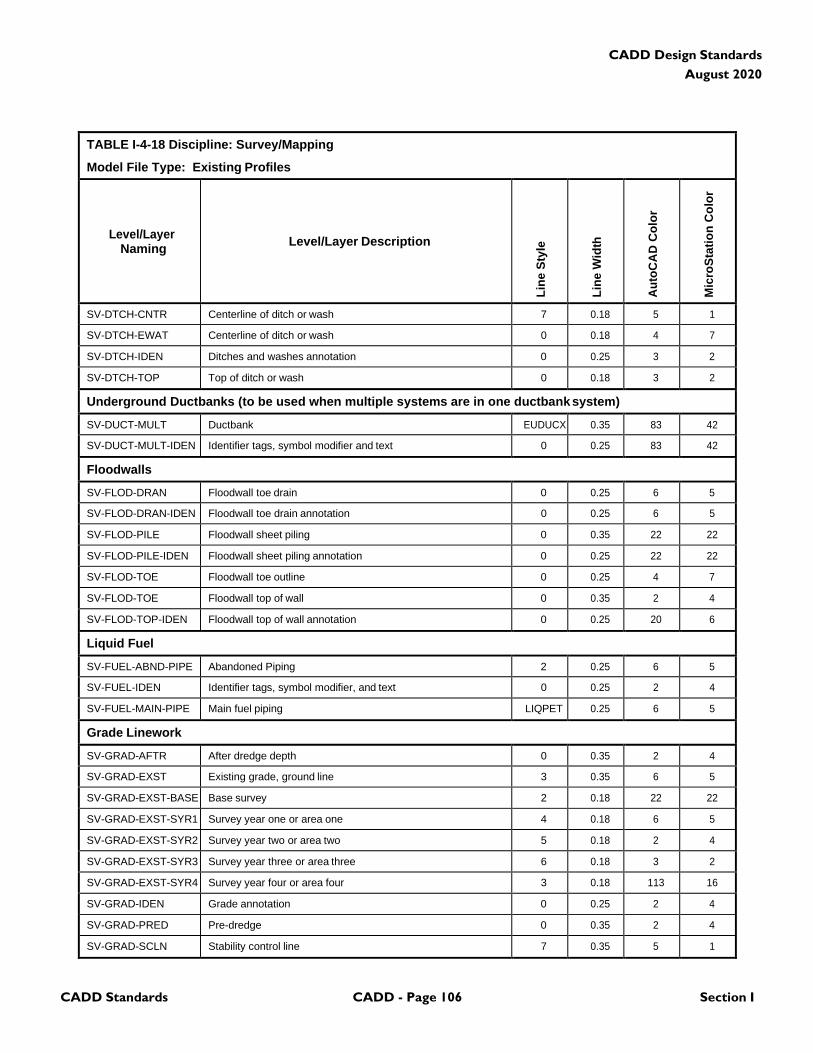
CADD Standards CADD - Page 106 Section I
CADD Design Standards
August 2020
TABLE I-4-18 Discipline: Survey/Mapping
Model File Type: Existing Profiles
Level/Layer
Naming
Level/Layer Description
Lin
e S
tyle
Lin
e W
idth
Au
toC
AD
Co
lor
Mic
roS
tati
on
Co
lor
SV-DTCH-CNTR Centerline of ditch or wash 7 0.18 5 1
SV-DTCH-EWAT Centerline of ditch or wash 0 0.18 4 7
SV-DTCH-IDEN Ditches and washes annotation 0 0.25 3 2
SV-DTCH-TOP Top of ditch or wash 0 0.18 3 2
Underground Ductbanks (to be used when multiple systems are in one ductbank system)
SV-DUCT-MULT Ductbank EUDUCX 0.35 83 42
SV-DUCT-MULT-IDEN Identifier tags, symbol modifier and text 0 0.25 83 42
Floodwalls
SV-FLOD-DRAN Floodwall toe drain 0 0.25 6 5
SV-FLOD-DRAN-IDEN Floodwall toe drain annotation 0 0.25 6 5
SV-FLOD-PILE Floodwall sheet piling 0 0.35 22 22
SV-FLOD-PILE-IDEN Floodwall sheet piling annotation 0 0.25 22 22
SV-FLOD-TOE Floodwall toe outline 0 0.25 4 7
SV-FLOD-TOE Floodwall top of wall 0 0.35 2 4
SV-FLOD-TOP-IDEN Floodwall top of wall annotation 0 0.25 20 6
Liquid Fuel
SV-FUEL-ABND-PIPE Abandoned Piping 2 0.25 6 5
SV-FUEL-IDEN Identifier tags, symbol modifier, and text 0 0.25 2 4
SV-FUEL-MAIN-PIPE Main fuel piping LIQPET 0.25 6 5
Grade Linework
SV-GRAD-AFTR After dredge depth 0 0.35 2 4
SV-GRAD-EXST Existing grade, ground line 3 0.35 6 5
SV-GRAD-EXST-BASE Base survey 2 0.18 22 22
SV-GRAD-EXST-SYR1 Survey year one or area one 4 0.18 6 5
SV-GRAD-EXST-SYR2 Survey year two or area two 5 0.18 2 4
SV-GRAD-EXST-SYR3 Survey year three or area three 6 0.18 3 2
SV-GRAD-EXST-SYR4 Survey year four or area four 3 0.18 113 16
SV-GRAD-IDEN Grade annotation 0 0.25 2 4
SV-GRAD-PRED Pre-dredge 0 0.35 2 4
SV-GRAD-SCLN Stability control line 7 0.35 5 1
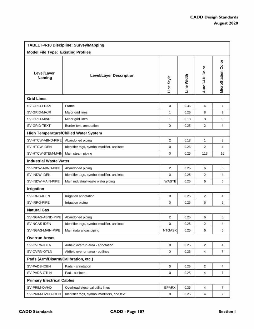
CADD Standards CADD - Page 107 Section I
CADD Design Standards
August 2020
TABLE I-4-18 Discipline: Survey/Mapping
Model File Type: Existing Profiles
Level/Layer
Naming
Level/Layer Description
Lin
e S
tyle
Lin
e W
idth
Au
toC
AD
Co
lor
Mic
roS
tati
on
Co
lor
Grid Lines
SV-GRID-FRAM Frame 0 0.35 4 7
SV-GRID-MAJR Major grid lines 1 0.25 8 9
SV-GRID-MINR Minor grid lines 1 0.18 8 9
SV-GRID-TEXT Border text, annotation 0 0.25 2 4
High Temperature/Chilled Water System
SV-HTCW-ABND-PIPE Abandoned piping 2 0.18 1 3
SV-HTCW-IDEN Identifier tags, symbol modifier, and text 0 0.25 2 4
SV-HTCW-STEM-MAIN Main steam piping 0 0.25 113 16
Industrial Waste Water
SV-INDW-ABND-PIPE Abandoned piping 2 0.25 6 5
SV-INDW-IDEN Identifier tags, symbol modifier, and text 0 0.25 2 4
SV-INDW-MAIN-PIPE Main industrial waste water piping IWASTE 0.25 6 5
Irrigation
SV-IRRG-IDEN Irrigation annotation 0 0.25 2 4
SV-IRRG-PIPE Irrigation piping 0 0.25 6 5
Natural Gas
SV-NGAS-ABND-PIPE Abandoned piping 2 0.25 6 5
SV-NGAS-IDEN Identifier tags, symbol modifier, and text 0 0.25 2 4
SV-NGAS-MAIN-PIPE Main natural gas piping NTGASX 0.25 6 5
Overrun Areas
SV-OVRN-IDEN Airfield overrun area - annotation 0 0.25 2 4
SV-OVRN-OTLN Airfield overrun area - outlines 0 0.25 4 7
Pads (Arm/Disarm/Calibration, etc.)
SV-PADS-IDEN Pads - annotation 0 0.25 2 4
SV-PADS-OTLN Pad - outlines 0 0.25 4 7
Primary Electrical Cables
SV-PRIM-OVHD Overhead electrical utility lines EPARX 0.35 4 7
SV-PRIM-OVHD-IDEN Identifier tags, symbol modifiers, and text 0 0.25 4 7
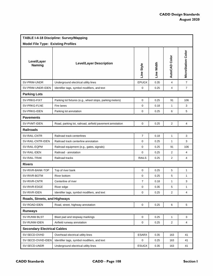
CADD Standards CADD - Page 108 Section I
CADD Design Standards
August 2020
TABLE I-4-18 Discipline: Survey/Mapping
Model File Type: Existing Profiles
Level/Layer
Naming
Level/Layer Description
Lin
e S
tyle
Lin
e W
idth
Au
toC
AD
Co
lor
Mic
roS
tati
on
Co
lor
SV-PRIM-UNDR Underground electrical utility lines EPUGX 0.35 4 7
SV-PRIM-UNDR-IDEN Identifier tags, symbol modifiers, and text 0 0.25 4 7
Parking Lots
SV-PRKG-FIXT Parking lot fixtures (e.g., wheel stops, parking meters) 0 0.25 91 106
SV-PRKG-FLNE Fire lanes 0 0.18 1 3
SV-PRKG-IDEN Parking lot annotation 0 0.25 6 5
Pavements
SV-PVMT-IDEN Road, parking lot, railroad, airfield pavement annotation 0 0.25 2 4
Railroads
SV-RAIL-CNTR Railroad track centerlines 7 0.18 1 3
SV-RAIL-CNTR-IDEN Railroad track centerline annotation 0 0.25 1 3
SV-RAIL-EQPM Railroad equipment (e.g., gates, signals) 0 0.25 91 106
SV-RAIL-IDEN Railroad - annotation 0 0.25 2 4
SV-RAIL-TRAK Railroad tracks RAILS 0.25 2 4
Rivers
SV-RIVR-BANK-TOP Top of river bank 0 0.25 5 1
SV-RIVR-BOTM River bottom 0 0.25 5 1
SV-RIVR-CNTR Centerline of river 7 0.18 1 3
SV-RIVR-EDGE River edge 0 0.35 5 1
SV-RIVR-IDEN Identifier tags, symbol modifiers, and text 0 0.25 2 4
Roads, Streets, and Highways
SV-ROAD-IDEN Road, street, highway annotation 0 0.25 6 5
Runways
SV-RUNW-BLST Blast pad and stopway markings 0 0.25 1 3
SV-RUNW-IDEN Airfield runway annotation 0 0.25 2 4
Secondary Electrical Cables
SV-SECD-OVHD Overhead electrical utility lines ESARX 0.35 163 41
SV-SECD-OVHD-IDEN Identifier tags, symbol modifiers, and text 0 0.25 163 41
SV-SECD-UNDR Underground electrical utility lines ESUGX 0.35 163 41
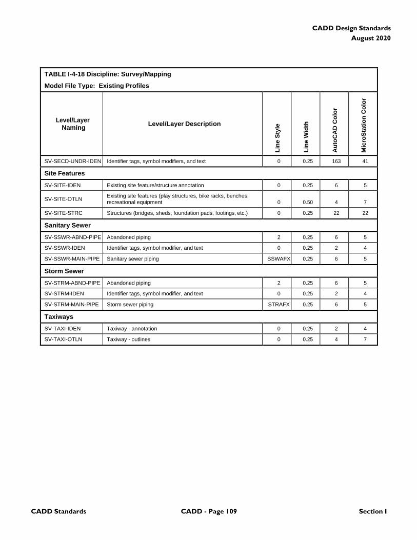
CADD Standards CADD - Page 109 Section I
CADD Design Standards
August 2020
TABLE I-4-18 Discipline: Survey/Mapping
Model File Type: Existing Profiles
Level/Layer
Naming
Level/Layer Description
Lin
e S
tyle
Lin
e W
idth
Au
toC
AD
Co
lor
Mic
roS
tati
on
Co
lor
SV-SECD-UNDR-IDEN Identifier tags, symbol modifiers, and text 0 0.25 163 41
Site Features
SV-SITE-IDEN Existing site feature/structure annotation 0 0.25 6 5
SV-SITE-OTLN Existing site features (play structures, bike racks, benches, recreational equipment
0
0.50
4
7
SV-SITE-STRC Structures (bridges, sheds, foundation pads, footings, etc.) 0 0.25 22 22
Sanitary Sewer
SV-SSWR-ABND-PIPE Abandoned piping 2 0.25 6 5
SV-SSWR-IDEN Identifier tags, symbol modifier, and text 0 0.25 2 4
SV-SSWR-MAIN-PIPE Sanitary sewer piping SSWAFX 0.25 6 5
Storm Sewer
SV-STRM-ABND-PIPE Abandoned piping 2 0.25 6 5
SV-STRM-IDEN Identifier tags, symbol modifier, and text 0 0.25 2 4
SV-STRM-MAIN-PIPE Storm sewer piping STRAFX 0.25 6 5
Taxiways
SV-TAXI-IDEN Taxiway - annotation 0 0.25 2 4
SV-TAXI-OTLN Taxiway - outlines 0 0.25 4 7
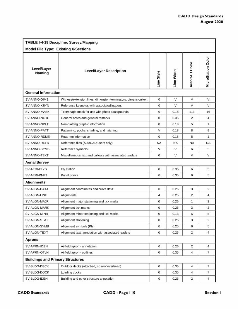
CADD Standards CADD - Page 110 Section I
CADD Design Standards
August 2020
TABLE I-4-19 Discipline: Survey/Mapping
Model File Type: Existing X-Sections
Level/Layer
Naming
Level/Layer Description
Lin
e S
tyle
Lin
e W
idth
Au
toC
AD
Co
lor
Mic
roS
tati
on
Co
lor
General Information
SV-ANNO-DIMS Witness/extension lines, dimension terminators, dimension text 0 V V V
SV-ANNO-KEYN Reference keynotes with associated leaders 0 V V V
SV-ANNO-MASK Text/shape mask for use with photo backgrounds 0 0.18 113 16
SV-ANNO-NOTE General notes and general remarks 0 0.35 2 4
SV-ANNO-NPLT Non-plotting graphic information 0 0.18 5 1
SV-ANNO-PATT Patterning, poche, shading, and hatching V 0.18 8 9
SV-ANNO-RDME Read-me information 0 0.18 5 1
SV-ANNO-REFR Reference files (AutoCAD users only) NA NA NA NA
SV-ANNO-SYMB Reference symbols V V 6 5
SV-ANNO-TEXT Miscellaneous text and callouts with associated leaders 0 V V V
Aerial Survey
SV-AERI-FLYS Fly station 0 0.35 6 5
SV-AERI-PNPT Panel points 0 0.35 6 5
Alignments
SV-ALGN-DATA Alignment coordinates and curve data 0 0.25 3 2
SV-ALGN-LINE Alignments 4 0.25 2 4
SV-ALGN-MAJR Alignment major stationing and tick marks 0 0.25 1 3
SV-ALGN-MARK Alignment tick marks 0 0.25 3 2
SV-ALGN-MINR Alignment minor stationing and tick marks 0 0.18 6 5
SV-ALGN-STAT Alignment stationing 0 0.25 3 2
SV-ALGN-SYMB Alignment symbols (PIs) 0 0.25 6 5
SV-ALGN-TEXT Alignment text, annotation with associated leaders 0 0.25 2 4
Aprons
SV-APRN-IDEN Airfield apron - annotation 0 0.25 2 4
SV-APRN-OTLN Airfield apron - outlines 0 0.35 4 7
Buildings and Primary Structures
SV-BLDG-DECK Outdoor decks (attached, no roof overhead) 0 0.35 4 7
SV-BLDG-DOCK Loading docks 0 0.35 4 7
SV-BLDG-IDEN Building and other structure annotation 0 0.25 2 4
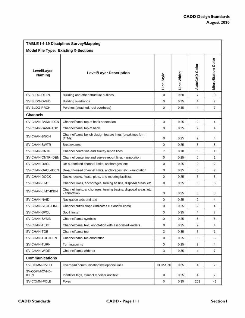
CADD Standards CADD - Page 111 Section I
CADD Design Standards
August 2020
TABLE I-4-19 Discipline: Survey/Mapping
Model File Type: Existing X-Sections
Level/Layer
Naming
Level/Layer Description
Lin
e S
tyle
Lin
e W
idth
Au
toC
AD
Co
lor
Mic
roS
tati
on
Co
lor
SV-BLDG-OTLN Building and other structure outlines 0 0.50 7 0
SV-BLDG-OVHD Building overhangs 0 0.35 4 7
SV-BLDG-PRCH Porches (attached, roof overhead) 0 0.35 4 7
Channels
SV-CHAN-BANK-IDEN Channel/canal top of bank annotation 0 0.25 2 4
SV-CHAN-BANK-TOP Channel/canal top of bank 0 0.25 2 4
SV-CHAN-BNCH Channel/canal bench design feature lines (breaklines form DTMs)
0
0.25
2
4
SV-CHAN-BWTR Breakwaters 0 0.25 6 5
SV-CHAN-CNTR Channel centerline and survey report lines 7 0.18 5 1
SV-CHAN-CNTR-IDEN Channel centerline and survey report lines - annotation 0 0.25 5 1
SV-CHAN-DACL De-authorized channel limits, anchorages, etc 0 0.25 3 2
SV-CHAN-DACL-IDEN De-authorized channel limits, anchorages, etc. - annotation 0 0.25 3 2
SV-CHAN-DOCK Docks, decks, floats, piers, and mooring facilities 0 0.25 6 5
SV-CHAN-LIMT Channel limits, anchorages, turning basins, disposal areas, etc. 0 0.25 6 5
SV-CHAN-LIMT-IDEN Channel limits, anchorages, turning basins, disposal areas, etc. - annotation
0
0.25
6
5
SV-CHAN-NAID Navigation aids and text 0 0.25 2 4
SV-CHAN-SLOP-LINE Channel cut/fill slope (Indicates cut and fill lines) 0 0.25 2 4
SV-CHAN-SPOL Spoil limits 0 0.35 4 7
SV-CHAN-SYMB Channel/canal symbols 0 0.25 6 5
SV-CHAN-TEXT Channel/canal text, annotation with associated leaders 0 0.25 2 4
SV-CHAN-TOE Channel/canal toe 3 0.35 5 1
SV-CHAN-TOE-IDEN Channel/canal toe annotation 0 0.25 6 5
SV-CHAN-TURN Turning points 0 0.25 2 4
SV-CHAN-WIDE Channel/canal widener 3 0.35 4 7
Communications
SV-COMM-OVHD Overhead communications/telephone lines COMARX 0.35 4 7
SV-COMM-OVHD- IDEN
Identifier tags, symbol modifier and text
0
0.25
4
7
SV-COMM-POLE Poles 0 0.35 203 45
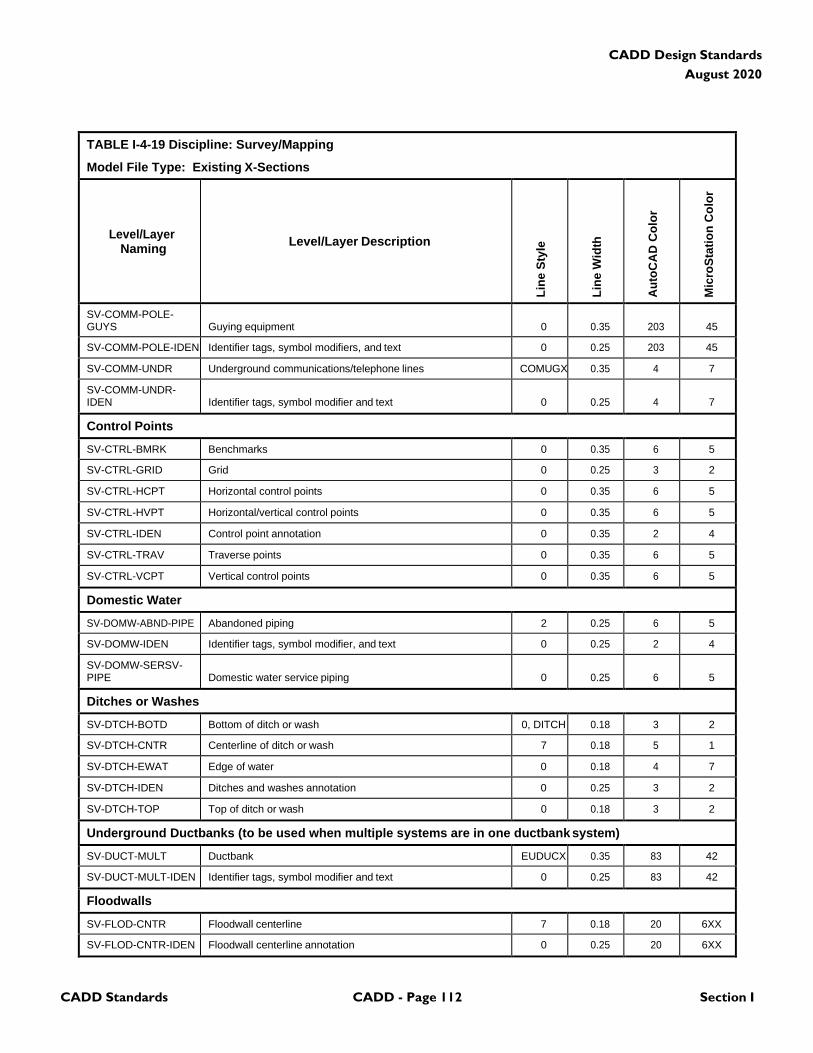
CADD Standards CADD - Page 112 Section I
CADD Design Standards
August 2020
TABLE I-4-19 Discipline: Survey/Mapping
Model File Type: Existing X-Sections
Level/Layer
Naming
Level/Layer Description
Lin
e S
tyle
Lin
e W
idth
Au
toC
AD
Co
lor
Mic
roS
tati
on
Co
lor
SV-COMM-POLE- GUYS
Guying equipment
0
0.35
203
45
SV-COMM-POLE-IDEN Identifier tags, symbol modifiers, and text 0 0.25 203 45
SV-COMM-UNDR Underground communications/telephone lines COMUGX 0.35 4 7
SV-COMM-UNDR- IDEN
Identifier tags, symbol modifier and text
0
0.25
4
7
Control Points
SV-CTRL-BMRK Benchmarks 0 0.35 6 5
SV-CTRL-GRID Grid 0 0.25 3 2
SV-CTRL-HCPT Horizontal control points 0 0.35 6 5
SV-CTRL-HVPT Horizontal/vertical control points 0 0.35 6 5
SV-CTRL-IDEN Control point annotation 0 0.35 2 4
SV-CTRL-TRAV Traverse points 0 0.35 6 5
SV-CTRL-VCPT Vertical control points 0 0.35 6 5
Domestic Water
SV-DOMW-ABND-PIPE Abandoned piping 2 0.25 6 5
SV-DOMW-IDEN Identifier tags, symbol modifier, and text 0 0.25 2 4
SV-DOMW-SERSV- PIPE
Domestic water service piping
0
0.25
6
5
Ditches or Washes
SV-DTCH-BOTD Bottom of ditch or wash 0, DITCH 0.18 3 2
SV-DTCH-CNTR Centerline of ditch or wash 7 0.18 5 1
SV-DTCH-EWAT Edge of water 0 0.18 4 7
SV-DTCH-IDEN Ditches and washes annotation 0 0.25 3 2
SV-DTCH-TOP Top of ditch or wash 0 0.18 3 2
Underground Ductbanks (to be used when multiple systems are in one ductbank system)
SV-DUCT-MULT Ductbank EUDUCX 0.35 83 42
SV-DUCT-MULT-IDEN Identifier tags, symbol modifier and text 0 0.25 83 42
Floodwalls
SV-FLOD-CNTR Floodwall centerline 7 0.18 20 6XX
SV-FLOD-CNTR-IDEN Floodwall centerline annotation 0 0.25 20 6XX
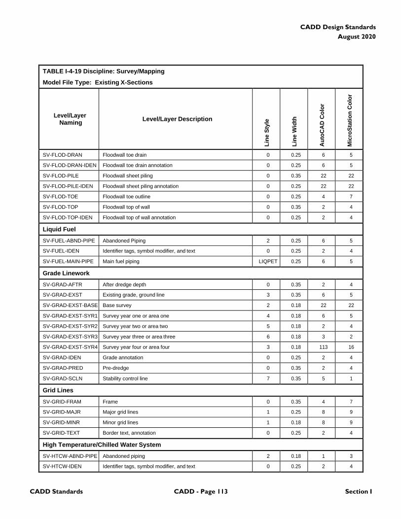
CADD Standards CADD - Page 113 Section I
CADD Design Standards
August 2020
TABLE I-4-19 Discipline: Survey/Mapping
Model File Type: Existing X-Sections
Level/Layer
Naming
Level/Layer Description
Lin
e S
tyle
Lin
e W
idth
Au
toC
AD
Co
lor
Mic
roS
tati
on
Co
lor
SV-FLOD-DRAN Floodwall toe drain 0 0.25 6 5
SV-FLOD-DRAN-IDEN Floodwall toe drain annotation 0 0.25 6 5
SV-FLOD-PILE Floodwall sheet piling 0 0.35 22 22
SV-FLOD-PILE-IDEN Floodwall sheet piling annotation 0 0.25 22 22
SV-FLOD-TOE Floodwall toe outline 0 0.25 4 7
SV-FLOD-TOP Floodwall top of wall 0 0.35 2 4
SV-FLOD-TOP-IDEN Floodwall top of wall annotation 0 0.25 2 4
Liquid Fuel
SV-FUEL-ABND-PIPE Abandoned Piping 2 0.25 6 5
SV-FUEL-IDEN Identifier tags, symbol modifier, and text 0 0.25 2 4
SV-FUEL-MAIN-PIPE Main fuel piping LIQPET 0.25 6 5
Grade Linework
SV-GRAD-AFTR After dredge depth 0 0.35 2 4
SV-GRAD-EXST Existing grade, ground line 3 0.35 6 5
SV-GRAD-EXST-BASE Base survey 2 0.18 22 22
SV-GRAD-EXST-SYR1 Survey year one or area one 4 0.18 6 5
SV-GRAD-EXST-SYR2 Survey year two or area two 5 0.18 2 4
SV-GRAD-EXST-SYR3 Survey year three or area three 6 0.18 3 2
SV-GRAD-EXST-SYR4 Survey year four or area four 3 0.18 113 16
SV-GRAD-IDEN Grade annotation 0 0.25 2 4
SV-GRAD-PRED Pre-dredge 0 0.35 2 4
SV-GRAD-SCLN Stability control line 7 0.35 5 1
Grid Lines
SV-GRID-FRAM Frame 0 0.35 4 7
SV-GRID-MAJR Major grid lines 1 0.25 8 9
SV-GRID-MINR Minor grid lines 1 0.18 8 9
SV-GRID-TEXT Border text, annotation 0 0.25 2 4
High Temperature/Chilled Water System
SV-HTCW-ABND-PIPE Abandoned piping 2 0.18 1 3
SV-HTCW-IDEN Identifier tags, symbol modifier, and text 0 0.25 2 4
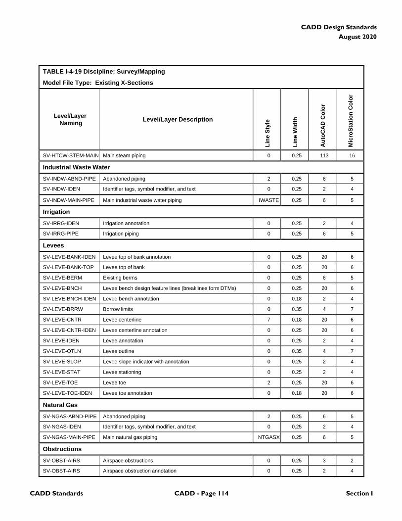
CADD Standards CADD - Page 114 Section I
CADD Design Standards
August 2020
TABLE I-4-19 Discipline: Survey/Mapping
Model File Type: Existing X-Sections
Level/Layer
Naming
Level/Layer Description
Lin
e S
tyle
Lin
e W
idth
Au
toC
AD
Co
lor
Mic
roS
tati
on
Co
lor
SV-HTCW-STEM-MAIN Main steam piping 0 0.25 113 16
Industrial Waste Water
SV-INDW-ABND-PIPE Abandoned piping 2 0.25 6 5
SV-INDW-IDEN Identifier tags, symbol modifier, and text 0 0.25 2 4
SV-INDW-MAIN-PIPE Main industrial waste water piping IWASTE 0.25 6 5
Irrigation
SV-IRRG-IDEN Irrigation annotation 0 0.25 2 4
SV-IRRG-PIPE Irrigation piping 0 0.25 6 5
Levees
SV-LEVE-BANK-IDEN Levee top of bank annotation 0 0.25 20 6
SV-LEVE-BANK-TOP Levee top of bank 0 0.25 20 6
SV-LEVE-BERM Existing berms 0 0.25 6 5
SV-LEVE-BNCH Levee bench design feature lines (breaklines form DTMs) 0 0.25 20 6
SV-LEVE-BNCH-IDEN Levee bench annotation 0 0.18 2 4
SV-LEVE-BRRW Borrow limits 0 0.35 4 7
SV-LEVE-CNTR Levee centerline 7 0.18 20 6
SV-LEVE-CNTR-IDEN Levee centerline annotation 0 0.25 20 6
SV-LEVE-IDEN Levee annotation 0 0.25 2 4
SV-LEVE-OTLN Levee outline 0 0.35 4 7
SV-LEVE-SLOP Levee slope indicator with annotation 0 0.25 2 4
SV-LEVE-STAT Levee stationing 0 0.25 2 4
SV-LEVE-TOE Levee toe 2 0.25 20 6
SV-LEVE-TOE-IDEN Levee toe annotation 0 0.18 20 6
Natural Gas
SV-NGAS-ABND-PIPE Abandoned piping 2 0.25 6 5
SV-NGAS-IDEN Identifier tags, symbol modifier, and text 0 0.25 2 4
SV-NGAS-MAIN-PIPE Main natural gas piping NTGASX 0.25 6 5
Obstructions
SV-OBST-AIRS Airspace obstructions 0 0.25 3 2
SV-OBST-AIRS Airspace obstruction annotation 0 0.25 2 4
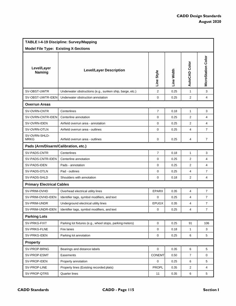
CADD Standards CADD - Page 115 Section I
CADD Design Standards
August 2020
TABLE I-4-19 Discipline: Survey/Mapping
Model File Type: Existing X-Sections
Level/Layer
Naming
Level/Layer Description
Lin
e S
tyle
Lin
e W
idth
Au
toC
AD
Co
lor
Mic
roS
tati
on
Co
lor
SV-OBST-UWTR Underwater obstructions (e.g., sunken ship, barge, etc.) 2 0.25 1 3
SV-OBST-UWTR-IDEN Underwater obstruction annotation 0 0.25 2 4
Overrun Areas
SV-OVRN-CNTR Centerlines 7 0.18 1 3
SV-OVRN-CNTR-IDEN Centerline annotation 0 0.25 2 4
SV-OVRN-IDEN Airfield overrun area - annotation 0 0.25 2 4
SV-OVRN-OTLN Airfield overrun area - outlines 0 0.25 4 7
SV-OVRN-SHLD- MRKG
Airfield overrun area - outlines
0
0.25
4
7
Pads (Arm/Disarm/Calibration, etc.)
SV-PADS-CNTR Centerlines 7 0.18 1 3
SV-PADS-CNTR-IDEN Centerline annotation 0 0.25 2 4
SV-PADS-IDEN Pads - annotation 0 0.25 2 4
SV-PADS-OTLN Pad - outlines 0 0.25 4 7
SV-PADS-SHLD Shoulders with annotation 0 0.18 2 4
Primary Electrical Cables
SV-PRIM-OVHD Overhead electrical utility lines EPARX 0.35 4 7
SV-PRIM-OVHD-IDEN Identifier tags, symbol modifiers, and text 0 0.25 4 7
SV-PRIM-UNDR Underground electrical utility lines EPUGX 0.35 4 7
SV-PRIM-UNDR-IDEN Identifier tags, symbol modifiers, and text 0 0.25 4 7
Parking Lots
SV-PRKG-FIXT Parking lot fixtures (e.g., wheel stops, parking meters) 0 0.25 91 106
SV-PRKG-FLNE Fire lanes 0 0.18 1 3
SV-PRKG-IDEN Parking lot annotation 0 0.25 6 5
Property
SV-PROP-BRNG Bearings and distance labels 0 0.35 6 5
SV-PROP-ESMT Easements CONEMT 0.50 7 0
SV-PROP-IDEN Property annotation 0 0.25 6 5
SV-PROP-LINE Property lines (Existing recorded plats) PROPL 0.35 2 4
SV-PROP-QTRS Quarter lines 11 0.35 6 5
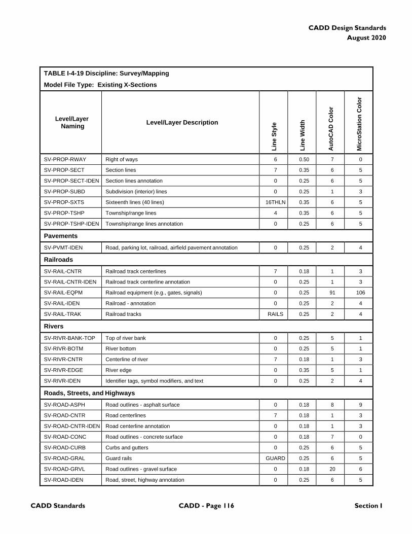
CADD Standards CADD - Page 116 Section I
CADD Design Standards
August 2020
TABLE I-4-19 Discipline: Survey/Mapping
Model File Type: Existing X-Sections
Level/Layer
Naming
Level/Layer Description
Lin
e S
tyle
Lin
e W
idth
Au
toC
AD
Co
lor
Mic
roS
tati
on
Co
lor
SV-PROP-RWAY Right of ways 6 0.50 7 0
SV-PROP-SECT Section lines 7 0.35 6 5
SV-PROP-SECT-IDEN Section lines annotation 0 0.25 6 5
SV-PROP-SUBD Subdivision (interior) lines 0 0.25 1 3
SV-PROP-SXTS Sixteenth lines (40 lines) 16THLN 0.35 6 5
SV-PROP-TSHP Township/range lines 4 0.35 6 5
SV-PROP-TSHP-IDEN Township/range lines annotation 0 0.25 6 5
Pavements
SV-PVMT-IDEN Road, parking lot, railroad, airfield pavement annotation 0 0.25 2 4
Railroads
SV-RAIL-CNTR Railroad track centerlines 7 0.18 1 3
SV-RAIL-CNTR-IDEN Railroad track centerline annotation 0 0.25 1 3
SV-RAIL-EQPM Railroad equipment (e.g., gates, signals) 0 0.25 91 106
SV-RAIL-IDEN Railroad - annotation 0 0.25 2 4
SV-RAIL-TRAK Railroad tracks RAILS 0.25 2 4
Rivers
SV-RIVR-BANK-TOP Top of river bank 0 0.25 5 1
SV-RIVR-BOTM River bottom 0 0.25 5 1
SV-RIVR-CNTR Centerline of river 7 0.18 1 3
SV-RIVR-EDGE River edge 0 0.35 5 1
SV-RIVR-IDEN Identifier tags, symbol modifiers, and text 0 0.25 2 4
Roads, Streets, and Highways
SV-ROAD-ASPH Road outlines - asphalt surface 0 0.18 8 9
SV-ROAD-CNTR Road centerlines 7 0.18 1 3
SV-ROAD-CNTR-IDEN Road centerline annotation 0 0.18 1 3
SV-ROAD-CONC Road outlines - concrete surface 0 0.18 7 0
SV-ROAD-CURB Curbs and gutters 0 0.25 6 5
SV-ROAD-GRAL Guard rails GUARD 0.25 6 5
SV-ROAD-GRVL Road outlines - gravel surface 0 0.18 20 6
SV-ROAD-IDEN Road, street, highway annotation 0 0.25 6 5
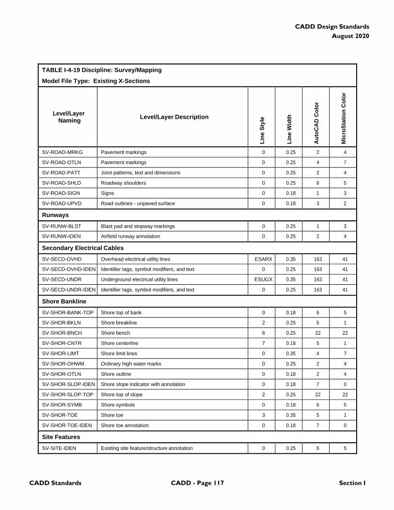
CADD Standards CADD - Page 117 Section I
CADD Design Standards
August 2020
TABLE I-4-19 Discipline: Survey/Mapping
Model File Type: Existing X-Sections
Level/Layer
Naming
Level/Layer Description
Lin
e S
tyle
Lin
e W
idth
Au
toC
AD
Co
lor
Mic
roS
tati
on
Co
lor
SV-ROAD-MRKG Pavement markings 0 0.25 2 4
SV-ROAD-OTLN Pavement markings 0 0.25 4 7
SV-ROAD-PATT Joint patterns, text and dimensions 0 0.25 2 4
SV-ROAD-SHLD Roadway shoulders 0 0.25 6 5
SV-ROAD-SIGN Signs 0 0.18 1 3
SV-ROAD-UPVD Road outlines - unpaved surface 0 0.18 3 2
Runways
SV-RUNW-BLST Blast pad and stopway markings 0 0.25 1 3
SV-RUNW-IDEN Airfield runway annotation 0 0.25 2 4
Secondary Electrical Cables
SV-SECD-OVHD Overhead electrical utility lines ESARX 0.35 163 41
SV-SECD-OVHD-IDEN Identifier tags, symbol modifiers, and text 0 0.25 163 41
SV-SECD-UNDR Underground electrical utility lines ESUGX 0.35 163 41
SV-SECD-UNDR-IDEN Identifier tags, symbol modifiers, and text 0 0.25 163 41
Shore Bankline
SV-SHOR-BANK-TOP Shore top of bank 0 0.18 6 5
SV-SHOR-BKLN Shore breakline 2 0.25 5 1
SV-SHOR-BNCH Shore bench 6 0.25 22 22
SV-SHOR-CNTR Shore centerline 7 0.18 5 1
SV-SHOR-LIMT Shore limit lines 0 0.35 4 7
SV-SHOR-OHWM Ordinary high water marks 0 0.25 2 4
SV-SHOR-OTLN Shore outline 0 0.18 2 4
SV-SHOR-SLOP-IDEN Shore slope indicator with annotation 0 0.18 7 0
SV-SHOR-SLOP-TOP Shore top of slope 2 0.25 22 22
SV-SHOR-SYMB Shore symbols 0 0.18 6 5
SV-SHOR-TOE Shore toe 3 0.35 5 1
SV-SHOR-TOE-IDEN Shore toe annotation 0 0.18 7 0
Site Features
SV-SITE-IDEN Existing site feature/structure annotation 0 0.25 6 5
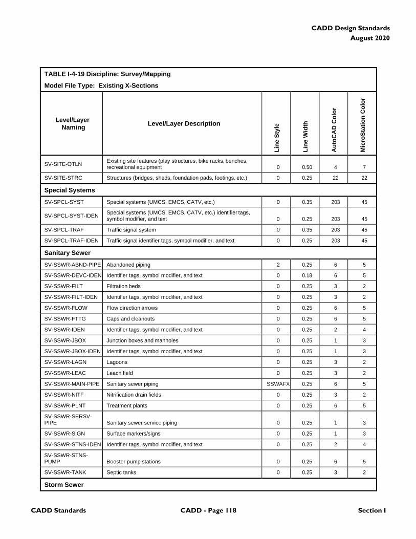
CADD Standards CADD - Page 118 Section I
CADD Design Standards
August 2020
TABLE I-4-19 Discipline: Survey/Mapping
Model File Type: Existing X-Sections
Level/Layer
Naming
Level/Layer Description
Lin
e S
tyle
Lin
e W
idth
Au
toC
AD
Co
lor
Mic
roS
tati
on
Co
lor
SV-SITE-OTLN Existing site features (play structures, bike racks, benches, recreational equipment
0
0.50
4
7
SV-SITE-STRC Structures (bridges, sheds, foundation pads, footings, etc.) 0 0.25 22 22
Special Systems
SV-SPCL-SYST Special systems (UMCS, EMCS, CATV, etc.) 0 0.35 203 45
SV-SPCL-SYST-IDEN Special systems (UMCS, EMCS, CATV, etc.) identifier tags, symbol modifier, and text
0
0.25
203
45
SV-SPCL-TRAF Traffic signal system 0 0.35 203 45
SV-SPCL-TRAF-IDEN Traffic signal identifier tags, symbol modifier, and text 0 0.25 203 45
Sanitary Sewer
SV-SSWR-ABND-PIPE Abandoned piping 2 0.25 6 5
SV-SSWR-DEVC-IDEN Identifier tags, symbol modifier, and text 0 0.18 6 5
SV-SSWR-FILT Filtration beds 0 0.25 3 2
SV-SSWR-FILT-IDEN Identifier tags, symbol modifier, and text 0 0.25 3 2
SV-SSWR-FLOW Flow direction arrows 0 0.25 6 5
SV-SSWR-FTTG Caps and cleanouts 0 0.25 6 5
SV-SSWR-IDEN Identifier tags, symbol modifier, and text 0 0.25 2 4
SV-SSWR-JBOX Junction boxes and manholes 0 0.25 1 3
SV-SSWR-JBOX-IDEN Identifier tags, symbol modifier, and text 0 0.25 1 3
SV-SSWR-LAGN Lagoons 0 0.25 3 2
SV-SSWR-LEAC Leach field 0 0.25 3 2
SV-SSWR-MAIN-PIPE Sanitary sewer piping SSWAFX 0.25 6 5
SV-SSWR-NITF Nitrification drain fields 0 0.25 3 2
SV-SSWR-PLNT Treatment plants 0 0.25 6 5
SV-SSWR-SERSV- PIPE
Sanitary sewer service piping
0
0.25
1
3
SV-SSWR-SIGN Surface markers/signs 0 0.25 1 3
SV-SSWR-STNS-IDEN Identifier tags, symbol modifier, and text 0 0.25 2 4
SV-SSWR-STNS- PUMP
Booster pump stations
0
0.25
6
5
SV-SSWR-TANK Septic tanks 0 0.25 3 2
Storm Sewer

CADD Standards CADD - Page 119 Section I
CADD Design Standards
August 2020
TABLE I-4-19 Discipline: Survey/Mapping
Model File Type: Existing X-Sections
Level/Layer
Naming
Level/Layer Description
Lin
e S
tyle
Lin
e W
idth
Au
toC
AD
Co
lor
Mic
roS
tati
on
Co
lor
SV-STRM-ABND-PIPE Abandoned piping 2 0.25 6 5
SV-STRM-AFFF AFFF lagoon/detention pond 0 0.25 3 2
SV-STRM-CHUT Chutes and concrete erosion control structures 0 0.25 1 3
SV-STRM-CULV Culverts CULVRT 0.25 3 2
SV-STRM-DEVC Downspouts, flumes, oil/water separators, and flap gates 0 0.25 6 5
SV-STRM-FLOW Flow direction arrows 0 0.25 6 5
SV-STRM-FMON Flow monitoring station 0 0.25 6 5
SV-STRM-FTTG Caps and cleanouts 0 0.25 6 5
SV-STRM-HDWL Headwalls and endwalls 0 0.35 7 0
SV-STRM-IDEN Identifier tags, symbol modifier, and text 0 0.25 2 4
SV-STRM-INLT Inlets (curb, surface, and catch basins) 0 0.25 3 2
SV-STRM-LAGN Lagoons, ponds, watersheds, and basins 0 0.25 3 2
SV-STRM-MAIN-PIPE Storm sewer piping STRAFX 0.25 6 5
SV-STRM-MHOL Storm sewer piping 0 0.25 1 3
SV-STRM-ROOF Roof drain line 0 0.25 3 2
SV-STRM-SERSV- PIPE
Storm sewer service piping
0
0.25
1
3
SV-STRM-SIGN Surface markers/signs 0 0.25 1 3
SV-STRM-STNS-IDEN Identifier tags, symbol modifier, and text 0 0.25 2 4
SV-STRM-STNS- PUMP
Pump stations
0
0.25
6
5
SV-STRM-SUBS-PIPE Subsurface drain piping 0 0.25 3 2
Survey
SV-SURV-DATA Survey data (benchmarks and horizontal control points or monuments
0
0.25
6
5
SV-SURV-IDEN Survey, baseline, and control line annotation 0 0.25 6 5
SV-SURV-LINE Survey, baseline, and control line 2 0.25 4 7
SV-SURV-SYMB Survey line symbol (PIs) 0 0.35 2 4
Taxiways
SV-TAXI-IDEN Taxiway - annotation 0 0.25 2 4
SV-TAXI-OTLN Taxiway - outlines 0 0.25 4 7
Topography
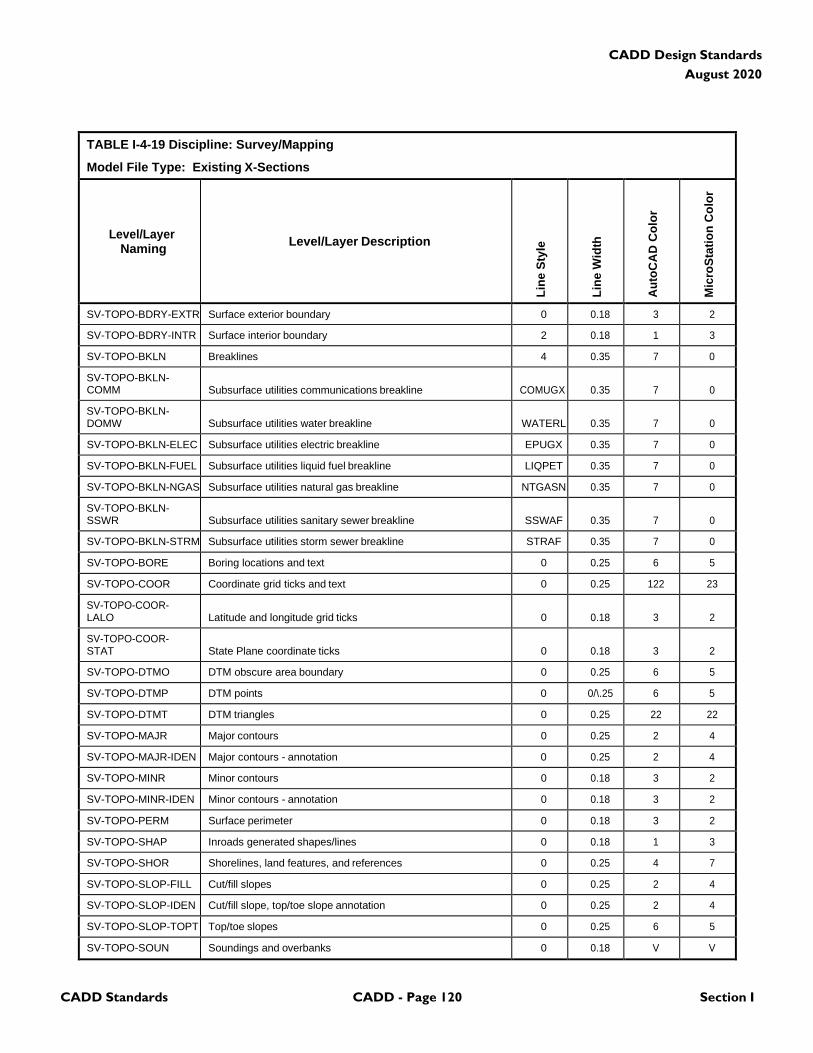
CADD Standards CADD - Page 120 Section I
CADD Design Standards
August 2020
TABLE I-4-19 Discipline: Survey/Mapping
Model File Type: Existing X-Sections
Level/Layer
Naming
Level/Layer Description
Lin
e S
tyle
Lin
e W
idth
Au
toC
AD
Co
lor
Mic
roS
tati
on
Co
lor
SV-TOPO-BDRY-EXTR Surface exterior boundary 0 0.18 3 2
SV-TOPO-BDRY-INTR Surface interior boundary 2 0.18 1 3
SV-TOPO-BKLN Breaklines 4 0.35 7 0
SV-TOPO-BKLN- COMM
Subsurface utilities communications breakline
COMUGX
0.35
7
0
SV-TOPO-BKLN- DOMW
Subsurface utilities water breakline
WATERL
0.35
7
0
SV-TOPO-BKLN-ELEC Subsurface utilities electric breakline EPUGX 0.35 7 0
SV-TOPO-BKLN-FUEL Subsurface utilities liquid fuel breakline LIQPET 0.35 7 0
SV-TOPO-BKLN-NGAS Subsurface utilities natural gas breakline NTGASN 0.35 7 0
SV-TOPO-BKLN- SSWR
Subsurface utilities sanitary sewer breakline
SSWAF
0.35
7
0
SV-TOPO-BKLN-STRM Subsurface utilities storm sewer breakline STRAF 0.35 7 0
SV-TOPO-BORE Boring locations and text 0 0.25 6 5
SV-TOPO-COOR Coordinate grid ticks and text 0 0.25 122 23
SV-TOPO-COOR- LALO
Latitude and longitude grid ticks
0
0.18
3
2
SV-TOPO-COOR- STAT
State Plane coordinate ticks
0
0.18
3
2
SV-TOPO-DTMO DTM obscure area boundary 0 0.25 6 5
SV-TOPO-DTMP DTM points 0 0/\.25 6 5
SV-TOPO-DTMT DTM triangles 0 0.25 22 22
SV-TOPO-MAJR Major contours 0 0.25 2 4
SV-TOPO-MAJR-IDEN Major contours - annotation 0 0.25 2 4
SV-TOPO-MINR Minor contours 0 0.18 3 2
SV-TOPO-MINR-IDEN Minor contours - annotation 0 0.18 3 2
SV-TOPO-PERM Surface perimeter 0 0.18 3 2
SV-TOPO-SHAP Inroads generated shapes/lines 0 0.18 1 3
SV-TOPO-SHOR Shorelines, land features, and references 0 0.25 4 7
SV-TOPO-SLOP-FILL Cut/fill slopes 0 0.25 2 4
SV-TOPO-SLOP-IDEN Cut/fill slope, top/toe slope annotation 0 0.25 2 4
SV-TOPO-SLOP-TOPT Top/toe slopes 0 0.25 6 5
SV-TOPO-SOUN Soundings and overbanks 0 0.18 V V
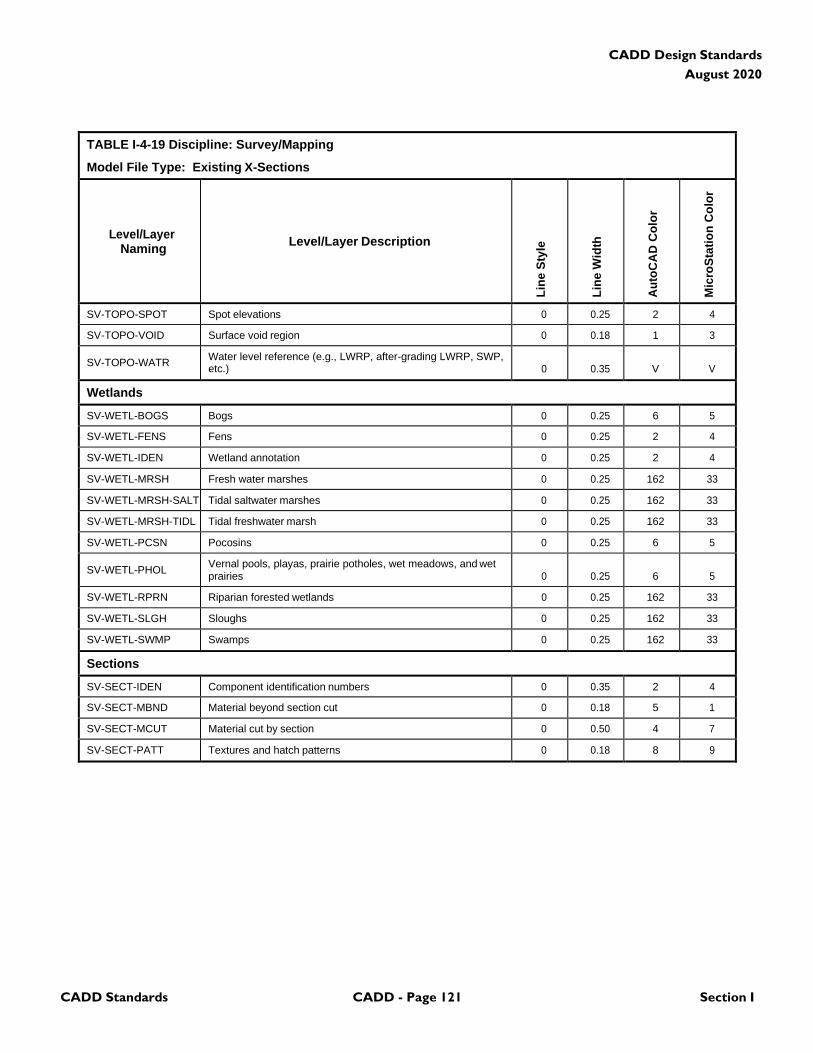
CADD Standards CADD - Page 121 Section I
CADD Design Standards
August 2020
TABLE I-4-19 Discipline: Survey/Mapping
Model File Type: Existing X-Sections
Level/Layer
Naming
Level/Layer Description
Lin
e S
tyle
Lin
e W
idth
Au
toC
AD
Co
lor
Mic
roS
tati
on
Co
lor
SV-TOPO-SPOT Spot elevations 0 0.25 2 4
SV-TOPO-VOID Surface void region 0 0.18 1 3
SV-TOPO-WATR Water level reference (e.g., LWRP, after-grading LWRP, SWP, etc.)
0
0.35
V
V
Wetlands
SV-WETL-BOGS Bogs 0 0.25 6 5
SV-WETL-FENS Fens 0 0.25 2 4
SV-WETL-IDEN Wetland annotation 0 0.25 2 4
SV-WETL-MRSH Fresh water marshes 0 0.25 162 33
SV-WETL-MRSH-SALT Tidal saltwater marshes 0 0.25 162 33
SV-WETL-MRSH-TIDL Tidal freshwater marsh 0 0.25 162 33
SV-WETL-PCSN Pocosins 0 0.25 6 5
SV-WETL-PHOL Vernal pools, playas, prairie potholes, wet meadows, and wet prairies
0
0.25
6
5
SV-WETL-RPRN Riparian forested wetlands 0 0.25 162 33
SV-WETL-SLGH Sloughs 0 0.25 162 33
SV-WETL-SWMP Swamps 0 0.25 162 33
Sections
SV-SECT-IDEN Component identification numbers 0 0.35 2 4
SV-SECT-MBND Material beyond section cut 0 0.18 5 1
SV-SECT-MCUT Material cut by section 0 0.50 4 7
SV-SECT-PATT Textures and hatch patterns 0 0.18 8 9
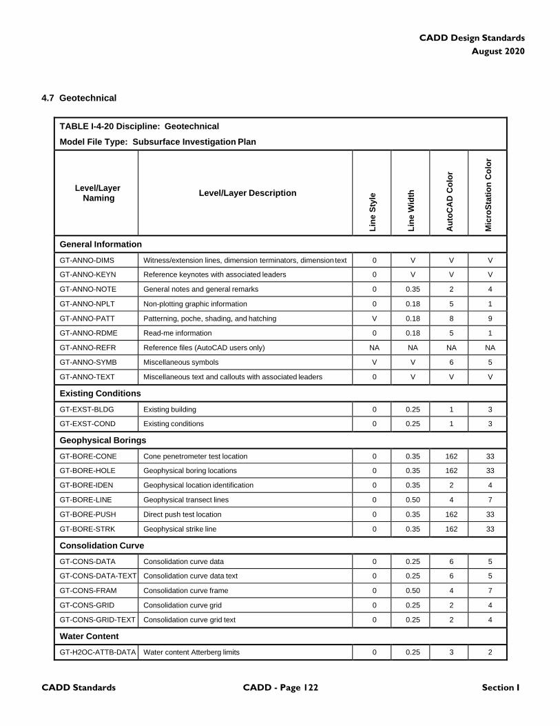
CADD Standards CADD - Page 122 Section I
CADD Design Standards
August 2020
4.7 Geotechnical
TABLE I-4-20 Discipline: Geotechnical
Model File Type: Subsurface Investigation Plan
Level/Layer
Naming
Level/Layer Description
Lin
e S
tyle
Lin
e W
idth
Au
toC
AD
Co
lor
Mic
roS
tati
on
Co
lor
General Information
GT-ANNO-DIMS Witness/extension lines, dimension terminators, dimension text 0 V V V
GT-ANNO-KEYN Reference keynotes with associated leaders 0 V V V
GT-ANNO-NOTE General notes and general remarks 0 0.35 2 4
GT-ANNO-NPLT Non-plotting graphic information 0 0.18 5 1
GT-ANNO-PATT Patterning, poche, shading, and hatching V 0.18 8 9
GT-ANNO-RDME Read-me information 0 0.18 5 1
GT-ANNO-REFR Reference files (AutoCAD users only) NA NA NA NA
GT-ANNO-SYMB Miscellaneous symbols V V 6 5
GT-ANNO-TEXT Miscellaneous text and callouts with associated leaders 0 V V V
Existing Conditions
GT-EXST-BLDG Existing building 0 0.25 1 3
GT-EXST-COND Existing conditions 0 0.25 1 3
Geophysical Borings
GT-BORE-CONE Cone penetrometer test location 0 0.35 162 33
GT-BORE-HOLE Geophysical boring locations 0 0.35 162 33
GT-BORE-IDEN Geophysical location identification 0 0.35 2 4
GT-BORE-LINE Geophysical transect lines 0 0.50 4 7
GT-BORE-PUSH Direct push test location 0 0.35 162 33
GT-BORE-STRK Geophysical strike line 0 0.35 162 33
Consolidation Curve
GT-CONS-DATA Consolidation curve data 0 0.25 6 5
GT-CONS-DATA-TEXT Consolidation curve data text 0 0.25 6 5
GT-CONS-FRAM Consolidation curve frame 0 0.50 4 7
GT-CONS-GRID Consolidation curve grid 0 0.25 2 4
GT-CONS-GRID-TEXT Consolidation curve grid text 0 0.25 2 4
Water Content
GT-H2OC-ATTB-DATA Water content Atterberg limits 0 0.25 3 2
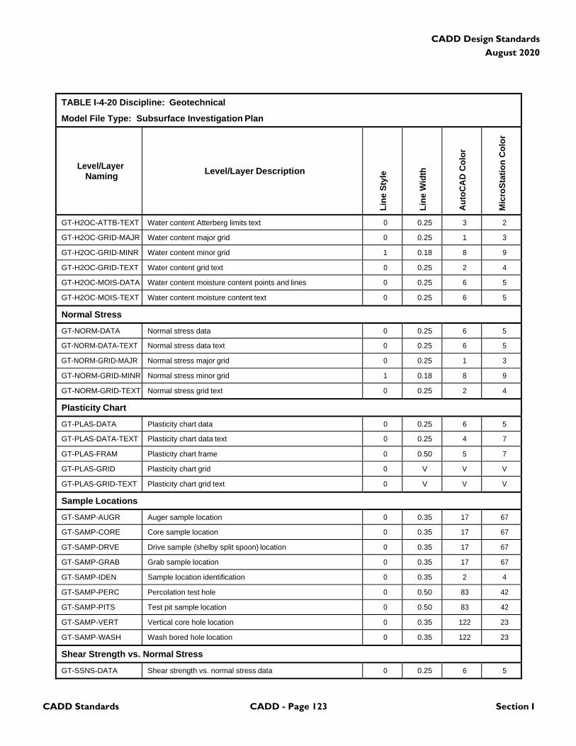
CADD Standards CADD - Page 123 Section I
CADD Design Standards
August 2020
TABLE I-4-20 Discipline: Geotechnical
Model File Type: Subsurface Investigation Plan
Level/Layer
Naming
Level/Layer Description
Lin
e S
tyle
Lin
e W
idth
Au
toC
AD
Co
lor
Mic
roS
tati
on
Co
lor
GT-H2OC-ATTB-TEXT Water content Atterberg limits text 0 0.25 3 2
GT-H2OC-GRID-MAJR Water content major grid 0 0.25 1 3
GT-H2OC-GRID-MINR Water content minor grid 1 0.18 8 9
GT-H2OC-GRID-TEXT Water content grid text 0 0.25 2 4
GT-H2OC-MOIS-DATA Water content moisture content points and lines 0 0.25 6 5
GT-H2OC-MOIS-TEXT Water content moisture content text 0 0.25 6 5
Normal Stress
GT-NORM-DATA Normal stress data 0 0.25 6 5
GT-NORM-DATA-TEXT Normal stress data text 0 0.25 6 5
GT-NORM-GRID-MAJR Normal stress major grid 0 0.25 1 3
GT-NORM-GRID-MINR Normal stress minor grid 1 0.18 8 9
GT-NORM-GRID-TEXT Normal stress grid text 0 0.25 2 4
Plasticity Chart
GT-PLAS-DATA Plasticity chart data 0 0.25 6 5
GT-PLAS-DATA-TEXT Plasticity chart data text 0 0.25 4 7
GT-PLAS-FRAM Plasticity chart frame 0 0.50 5 7
GT-PLAS-GRID Plasticity chart grid 0 V V V
GT-PLAS-GRID-TEXT Plasticity chart grid text 0 V V V
Sample Locations
GT-SAMP-AUGR Auger sample location 0 0.35 17 67
GT-SAMP-CORE Core sample location 0 0.35 17 67
GT-SAMP-DRVE Drive sample (shelby split spoon) location 0 0.35 17 67
GT-SAMP-GRAB Grab sample location 0 0.35 17 67
GT-SAMP-IDEN Sample location identification 0 0.35 2 4
GT-SAMP-PERC Percolation test hole 0 0.50 83 42
GT-SAMP-PITS Test pit sample location 0 0.50 83 42
GT-SAMP-VERT Vertical core hole location 0 0.35 122 23
GT-SAMP-WASH Wash bored hole location 0 0.35 122 23
Shear Strength vs. Normal Stress
GT-SSNS-DATA Shear strength vs. normal stress data 0 0.25 6 5
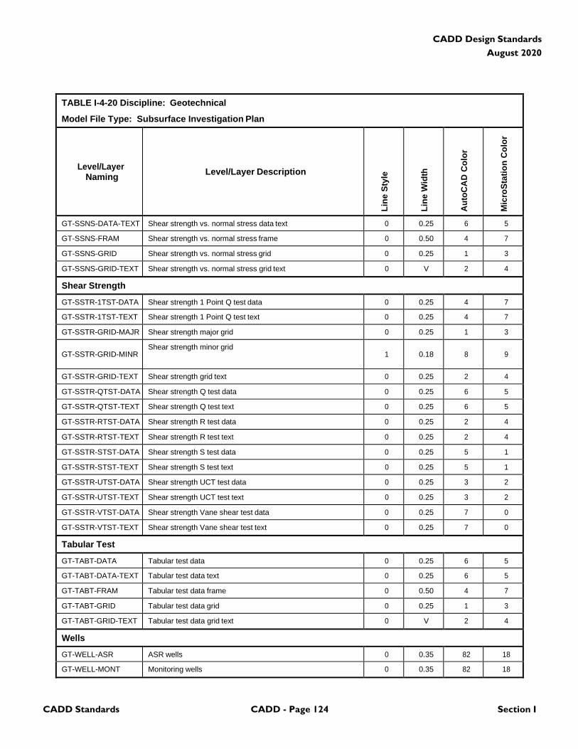
CADD Standards CADD - Page 124 Section I
CADD Design Standards
August 2020
TABLE I-4-20 Discipline: Geotechnical
Model File Type: Subsurface Investigation Plan
Level/Layer
Naming
Level/Layer Description
Lin
e S
tyle
Lin
e W
idth
Au
toC
AD
Co
lor
Mic
roS
tati
on
Co
lor
GT-SSNS-DATA-TEXT Shear strength vs. normal stress data text 0 0.25 6 5
GT-SSNS-FRAM Shear strength vs. normal stress frame 0 0.50 4 7
GT-SSNS-GRID Shear strength vs. normal stress grid 0 0.25 1 3
GT-SSNS-GRID-TEXT Shear strength vs. normal stress grid text 0 V 2 4
Shear Strength
GT-SSTR-1TST-DATA Shear strength 1 Point Q test data 0 0.25 4 7
GT-SSTR-1TST-TEXT Shear strength 1 Point Q test text 0 0.25 4 7
GT-SSTR-GRID-MAJR Shear strength major grid 0 0.25 1 3
GT-SSTR-GRID-MINR
Shear strength minor grid 1
0.18
8
9
GT-SSTR-GRID-TEXT Shear strength grid text 0 0.25 2 4
GT-SSTR-QTST-DATA Shear strength Q test data 0 0.25 6 5
GT-SSTR-QTST-TEXT Shear strength Q test text 0 0.25 6 5
GT-SSTR-RTST-DATA Shear strength R test data 0 0.25 2 4
GT-SSTR-RTST-TEXT Shear strength R test text 0 0.25 2 4
GT-SSTR-STST-DATA Shear strength S test data 0 0.25 5 1
GT-SSTR-STST-TEXT Shear strength S test text 0 0.25 5 1
GT-SSTR-UTST-DATA Shear strength UCT test data 0 0.25 3 2
GT-SSTR-UTST-TEXT Shear strength UCT test text 0 0.25 3 2
GT-SSTR-VTST-DATA Shear strength Vane shear test data 0 0.25 7 0
GT-SSTR-VTST-TEXT Shear strength Vane shear test text 0 0.25 7 0
Tabular Test
GT-TABT-DATA Tabular test data 0 0.25 6 5
GT-TABT-DATA-TEXT Tabular test data text 0 0.25 6 5
GT-TABT-FRAM Tabular test data frame 0 0.50 4 7
GT-TABT-GRID Tabular test data grid 0 0.25 1 3
GT-TABT-GRID-TEXT Tabular test data grid text 0 V 2 4
Wells
GT-WELL-ASR ASR wells 0 0.35 82 18
GT-WELL-MONT Monitoring wells 0 0.35 82 18
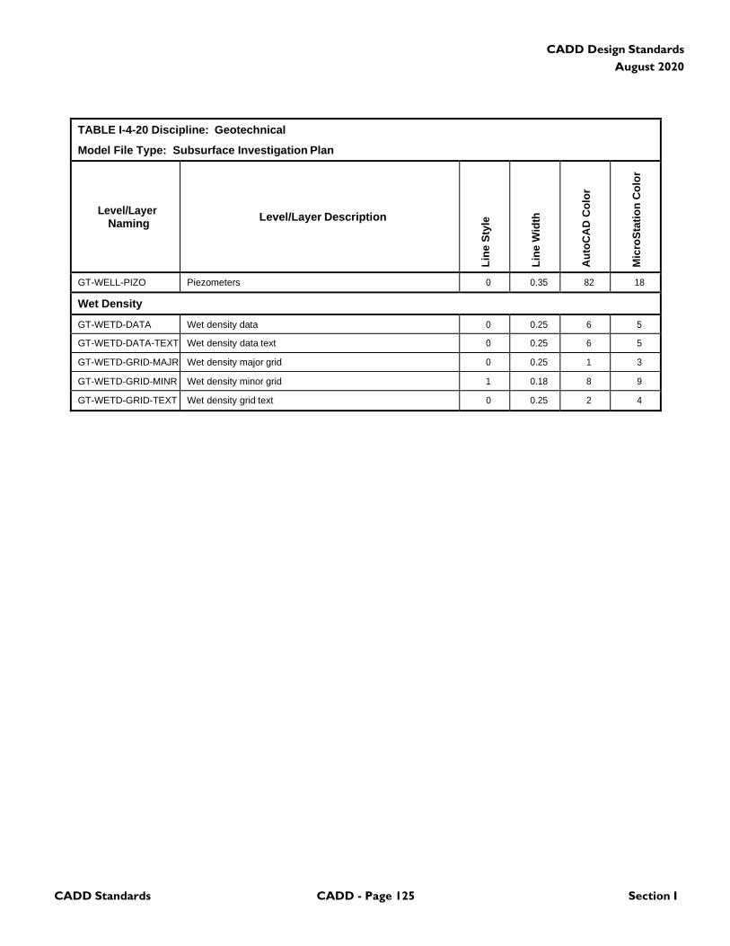
CADD Standards CADD - Page 125 Section I
CADD Design Standards
August 2020
TABLE I-4-20 Discipline: Geotechnical
Model File Type: Subsurface Investigation Plan
Level/Layer
Naming
Level/Layer Description
Lin
e S
tyle
Lin
e W
idth
Au
toC
AD
Co
lor
Mic
roS
tati
on
Co
lor
GT-WELL-PIZO Piezometers 0 0.35 82 18
Wet Density
GT-WETD-DATA Wet density data 0 0.25 6 5
GT-WETD-DATA-TEXT Wet density data text 0 0.25 6 5
GT-WETD-GRID-MAJR Wet density major grid 0 0.25 1 3
GT-WETD-GRID-MINR Wet density minor grid 1 0.18 8 9
GT-WETD-GRID-TEXT Wet density grid text 0 0.25 2 4
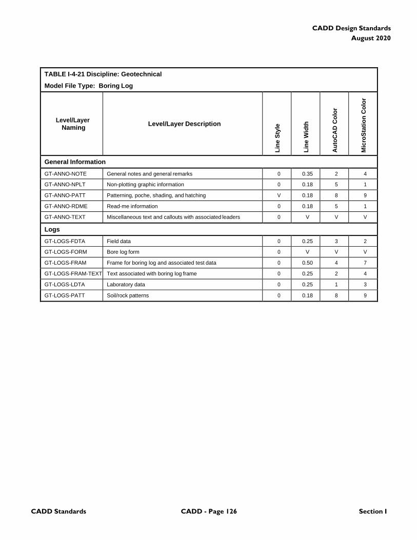
CADD Standards CADD - Page 126 Section I
CADD Design Standards
August 2020
TABLE I-4-21 Discipline: Geotechnical
Model File Type: Boring Log
Level/Layer
Naming
Level/Layer Description
Lin
e S
tyle
Lin
e W
idth
Au
toC
AD
Co
lor
Mic
roS
tati
on
Co
lor
General Information
GT-ANNO-NOTE General notes and general remarks 0 0.35 2 4
GT-ANNO-NPLT Non-plotting graphic information 0 0.18 5 1
GT-ANNO-PATT Patterning, poche, shading, and hatching V 0.18 8 9
GT-ANNO-RDME Read-me information 0 0.18 5 1
GT-ANNO-TEXT Miscellaneous text and callouts with associated leaders 0 V V V
Logs
GT-LOGS-FDTA Field data 0 0.25 3 2
GT-LOGS-FORM Bore log form 0 V V V
GT-LOGS-FRAM Frame for boring log and associated test data 0 0.50 4 7
GT-LOGS-FRAM-TEXT Text associated with boring log frame 0 0.25 2 4
GT-LOGS-LDTA Laboratory data 0 0.25 1 3
GT-LOGS-PATT Soil/rock patterns 0 0.18 8 9
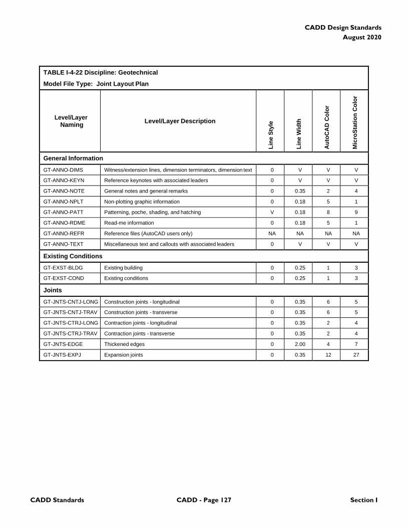
CADD Standards CADD - Page 127 Section I
CADD Design Standards
August 2020
TABLE I-4-22 Discipline: Geotechnical
Model File Type: Joint Layout Plan
Level/Layer
Naming
Level/Layer Description
Lin
e S
tyle
Lin
e W
idth
Au
toC
AD
Co
lor
Mic
roS
tati
on
Co
lor
General Information
GT-ANNO-DIMS Witness/extension lines, dimension terminators, dimension text 0 V V V
GT-ANNO-KEYN Reference keynotes with associated leaders 0 V V V
GT-ANNO-NOTE General notes and general remarks 0 0.35 2 4
GT-ANNO-NPLT Non-plotting graphic information 0 0.18 5 1
GT-ANNO-PATT Patterning, poche, shading, and hatching V 0.18 8 9
GT-ANNO-RDME Read-me information 0 0.18 5 1
GT-ANNO-REFR Reference files (AutoCAD users only) NA NA NA NA
GT-ANNO-TEXT Miscellaneous text and callouts with associated leaders 0 V V V
Existing Conditions
GT-EXST-BLDG Existing building 0 0.25 1 3
GT-EXST-COND Existing conditions 0 0.25 1 3
Joints
GT-JNTS-CNTJ-LONG Construction joints - longitudinal 0 0.35 6 5
GT-JNTS-CNTJ-TRAV Construction joints - transverse 0 0.35 6 5
GT-JNTS-CTRJ-LONG Contraction joints - longitudinal 0 0.35 2 4
GT-JNTS-CTRJ-TRAV Contraction joints - transverse 0 0.35 2 4
GT-JNTS-EDGE Thickened edges 0 2.00 4 7
GT-JNTS-EXPJ Expansion joints 0 0.35 12 27
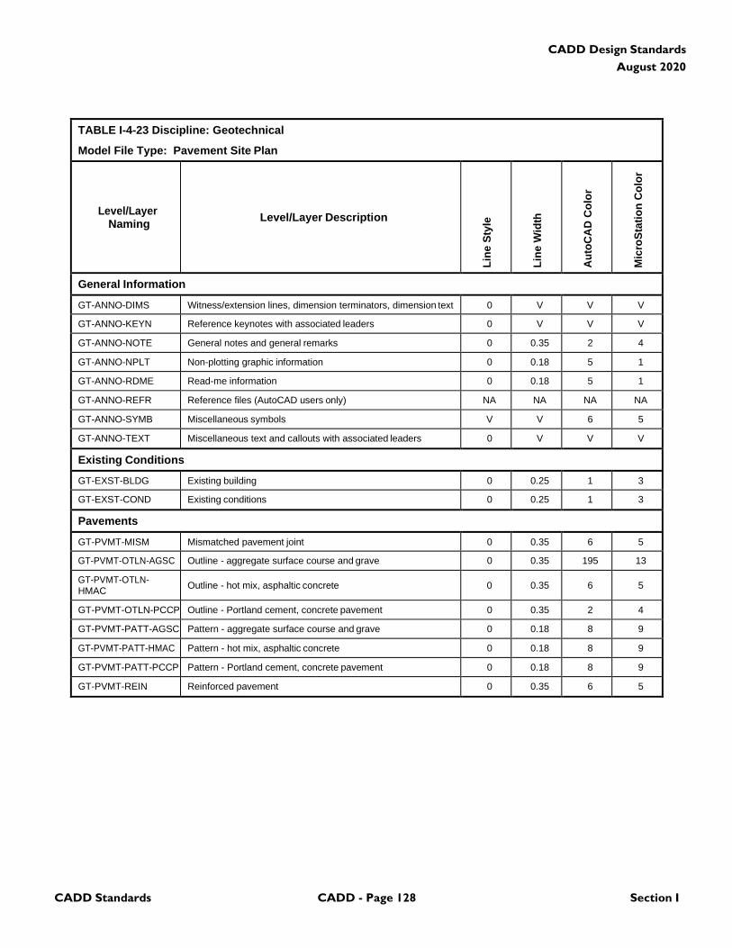
CADD Standards CADD - Page 128 Section I
CADD Design Standards
August 2020
TABLE I-4-23 Discipline: Geotechnical
Model File Type: Pavement Site Plan
Level/Layer
Naming
Level/Layer Description
Lin
e S
tyle
Lin
e W
idth
Au
toC
AD
Co
lor
Mic
roS
tati
on
Co
lor
General Information
GT-ANNO-DIMS Witness/extension lines, dimension terminators, dimension text 0 V V V
GT-ANNO-KEYN Reference keynotes with associated leaders 0 V V V
GT-ANNO-NOTE General notes and general remarks 0 0.35 2 4
GT-ANNO-NPLT Non-plotting graphic information 0 0.18 5 1
GT-ANNO-RDME Read-me information 0 0.18 5 1
GT-ANNO-REFR Reference files (AutoCAD users only) NA NA NA NA
GT-ANNO-SYMB Miscellaneous symbols V V 6 5
GT-ANNO-TEXT Miscellaneous text and callouts with associated leaders 0 V V V
Existing Conditions
GT-EXST-BLDG Existing building 0 0.25 1 3
GT-EXST-COND Existing conditions 0 0.25 1 3
Pavements
GT-PVMT-MISM Mismatched pavement joint 0 0.35 6 5
GT-PVMT-OTLN-AGSC Outline - aggregate surface course and grave 0 0.35 195 13
GT-PVMT-OTLN- HMAC
Outline - hot mix, asphaltic concrete
0
0.35
6
5
GT-PVMT-OTLN-PCCP Outline - Portland cement, concrete pavement 0 0.35 2 4
GT-PVMT-PATT-AGSC Pattern - aggregate surface course and grave 0 0.18 8 9
GT-PVMT-PATT-HMAC Pattern - hot mix, asphaltic concrete 0 0.18 8 9
GT-PVMT-PATT-PCCP Pattern - Portland cement, concrete pavement 0 0.18 8 9
GT-PVMT-REIN Reinforced pavement 0 0.35 6 5
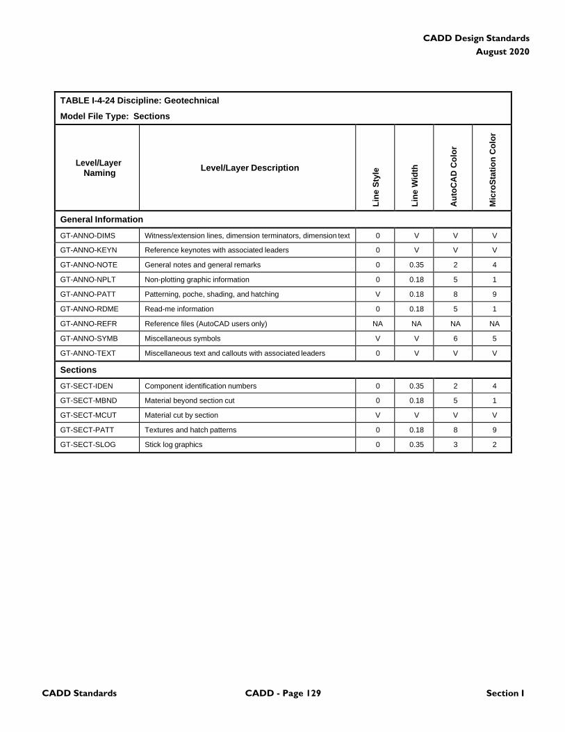
CADD Standards CADD - Page 129 Section I
CADD Design Standards
August 2020
TABLE I-4-24 Discipline: Geotechnical
Model File Type: Sections
Level/Layer
Naming
Level/Layer Description
Lin
e S
tyle
Lin
e W
idth
Au
toC
AD
Co
lor
Mic
roS
tati
on
Co
lor
General Information
GT-ANNO-DIMS Witness/extension lines, dimension terminators, dimension text 0 V V V
GT-ANNO-KEYN Reference keynotes with associated leaders 0 V V V
GT-ANNO-NOTE General notes and general remarks 0 0.35 2 4
GT-ANNO-NPLT Non-plotting graphic information 0 0.18 5 1
GT-ANNO-PATT Patterning, poche, shading, and hatching V 0.18 8 9
GT-ANNO-RDME Read-me information 0 0.18 5 1
GT-ANNO-REFR Reference files (AutoCAD users only) NA NA NA NA
GT-ANNO-SYMB Miscellaneous symbols V V 6 5
GT-ANNO-TEXT Miscellaneous text and callouts with associated leaders 0 V V V
Sections
GT-SECT-IDEN Component identification numbers 0 0.35 2 4
GT-SECT-MBND Material beyond section cut 0 0.18 5 1
GT-SECT-MCUT Material cut by section V V V V
GT-SECT-PATT Textures and hatch patterns 0 0.18 8 9
GT-SECT-SLOG Stick log graphics 0 0.35 3 2

CADD Standards CADD - Page 130 Section I
CADD Design Standards
August 2020
TABLE I-4-25 Discipline: Geotechnical
Model File Type: Details
Level/Layer
Naming
Level/Layer Description
Lin
e S
tyle
Lin
e W
idth
Au
toC
AD
Co
lor
Mic
roS
tati
on
Co
lor
General Information
GT-ANNO-DIMS Witness/extension lines, dimension terminators, dimension text 0 V V V
GT-ANNO-KEYN Reference keynotes with associated leaders 0 V V V
GT-ANNO-NOTE General notes and general remarks 0 0.35 2 4
GT-ANNO-NPLT Non-plotting graphic information 0 0.18 5 1
GT-ANNO-PATT Patterning, poche, shading, and hatching V 0.18 8 9
GT-ANNO-RDME Read-me information 0 0.18 5 1
GT-ANNO-REFR Reference files (AutoCAD users only) NA NA NA NA
GT-ANNO-SYMB Miscellaneous symbols V V 6 5
GT-ANNO-TEXT Miscellaneous text and callouts with associated leaders 0 V V V
Detail Information
GT-DETL-GRPH Graphics, gridlines, non-text items V V V V
GT-DETL-INPD Inch-pound specific dimensions and notes V V V V
GT-DETL-METR Metric specific dimensions and notes V V V V
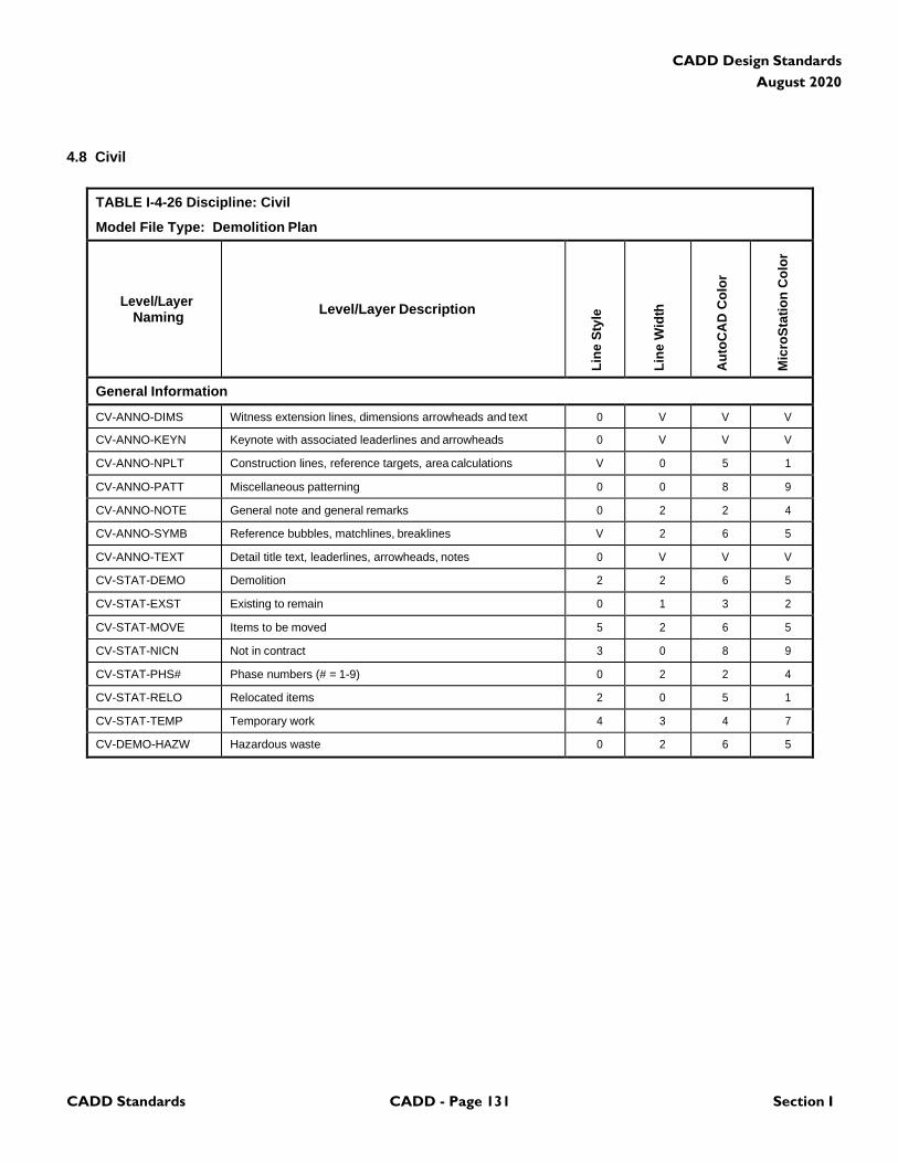
CADD Standards CADD - Page 131 Section I
CADD Design Standards
August 2020
4.8 Civil
TABLE I-4-26 Discipline: Civil
Model File Type: Demolition Plan
Level/Layer
Naming
Level/Layer Description
Lin
e S
tyle
Lin
e W
idth
Au
toC
AD
Co
lor
Mic
roS
tati
on
Co
lor
General Information
CV-ANNO-DIMS Witness extension lines, dimensions arrowheads and text 0 V V V
CV-ANNO-KEYN Keynote with associated leaderlines and arrowheads 0 V V V
CV-ANNO-NPLT Construction lines, reference targets, area calculations V 0 5 1
CV-ANNO-PATT Miscellaneous patterning 0 0 8 9
CV-ANNO-NOTE General note and general remarks 0 2 2 4
CV-ANNO-SYMB Reference bubbles, matchlines, breaklines V 2 6 5
CV-ANNO-TEXT Detail title text, leaderlines, arrowheads, notes 0 V V V
CV-STAT-DEMO Demolition 2 2 6 5
CV-STAT-EXST Existing to remain 0 1 3 2
CV-STAT-MOVE Items to be moved 5 2 6 5
CV-STAT-NICN Not in contract 3 0 8 9
CV-STAT-PHS# Phase numbers (# = 1-9) 0 2 2 4
CV-STAT-RELO Relocated items 2 0 5 1
CV-STAT-TEMP Temporary work 4 3 4 7
CV-DEMO-HAZW Hazardous waste 0 2 6 5
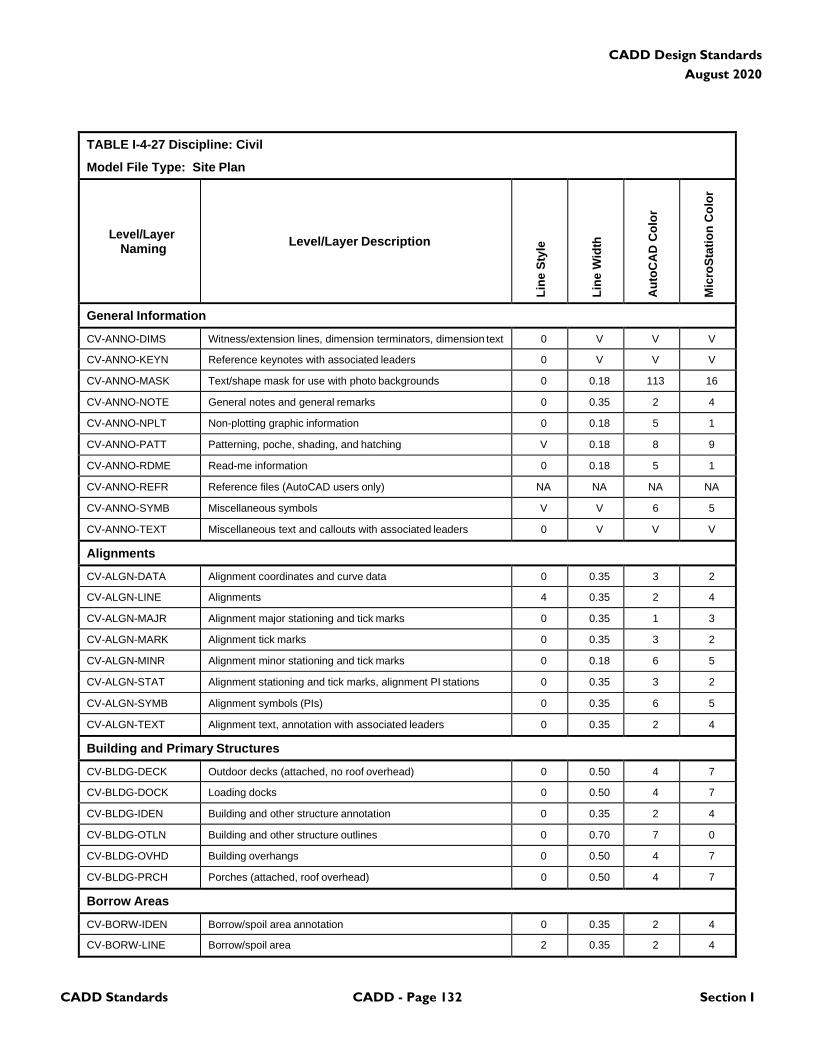
CADD Standards CADD - Page 132 Section I
CADD Design Standards
August 2020
TABLE I-4-27 Discipline: Civil
Model File Type: Site Plan
Level/Layer
Naming
Level/Layer Description
Lin
e S
tyle
Lin
e W
idth
Au
toC
AD
Co
lor
Mic
roS
tati
on
Co
lor
General Information
CV-ANNO-DIMS Witness/extension lines, dimension terminators, dimension text 0 V V V
CV-ANNO-KEYN Reference keynotes with associated leaders 0 V V V
CV-ANNO-MASK Text/shape mask for use with photo backgrounds 0 0.18 113 16
CV-ANNO-NOTE General notes and general remarks 0 0.35 2 4
CV-ANNO-NPLT Non-plotting graphic information 0 0.18 5 1
CV-ANNO-PATT Patterning, poche, shading, and hatching V 0.18 8 9
CV-ANNO-RDME Read-me information 0 0.18 5 1
CV-ANNO-REFR Reference files (AutoCAD users only) NA NA NA NA
CV-ANNO-SYMB Miscellaneous symbols V V 6 5
CV-ANNO-TEXT Miscellaneous text and callouts with associated leaders 0 V V V
Alignments
CV-ALGN-DATA Alignment coordinates and curve data 0 0.35 3 2
CV-ALGN-LINE Alignments 4 0.35 2 4
CV-ALGN-MAJR Alignment major stationing and tick marks 0 0.35 1 3
CV-ALGN-MARK Alignment tick marks 0 0.35 3 2
CV-ALGN-MINR Alignment minor stationing and tick marks 0 0.18 6 5
CV-ALGN-STAT Alignment stationing and tick marks, alignment PI stations 0 0.35 3 2
CV-ALGN-SYMB Alignment symbols (PIs) 0 0.35 6 5
CV-ALGN-TEXT Alignment text, annotation with associated leaders 0 0.35 2 4
Building and Primary Structures
CV-BLDG-DECK Outdoor decks (attached, no roof overhead) 0 0.50 4 7
CV-BLDG-DOCK Loading docks 0 0.50 4 7
CV-BLDG-IDEN Building and other structure annotation 0 0.35 2 4
CV-BLDG-OTLN Building and other structure outlines 0 0.70 7 0
CV-BLDG-OVHD Building overhangs 0 0.50 4 7
CV-BLDG-PRCH Porches (attached, roof overhead) 0 0.50 4 7
Borrow Areas
CV-BORW-IDEN Borrow/spoil area annotation 0 0.35 2 4
CV-BORW-LINE Borrow/spoil area 2 0.35 2 4
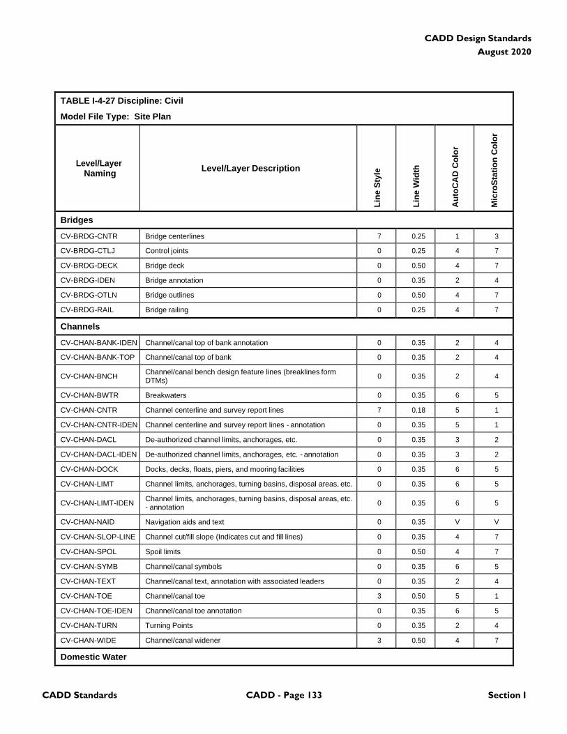
CADD Standards CADD - Page 133 Section I
CADD Design Standards
August 2020
TABLE I-4-27 Discipline: Civil
Model File Type: Site Plan
Level/Layer
Naming
Level/Layer Description
Lin
e S
tyle
Lin
e W
idth
Au
toC
AD
Co
lor
Mic
roS
tati
on
Co
lor
Bridges
CV-BRDG-CNTR Bridge centerlines 7 0.25 1 3
CV-BRDG-CTLJ Control joints 0 0.25 4 7
CV-BRDG-DECK Bridge deck 0 0.50 4 7
CV-BRDG-IDEN Bridge annotation 0 0.35 2 4
CV-BRDG-OTLN Bridge outlines 0 0.50 4 7
CV-BRDG-RAIL Bridge railing 0 0.25 4 7
Channels
CV-CHAN-BANK-IDEN Channel/canal top of bank annotation 0 0.35 2 4
CV-CHAN-BANK-TOP Channel/canal top of bank 0 0.35 2 4
CV-CHAN-BNCH Channel/canal bench design feature lines (breaklines form DTMs)
0
0.35
2
4
CV-CHAN-BWTR Breakwaters 0 0.35 6 5
CV-CHAN-CNTR Channel centerline and survey report lines 7 0.18 5 1
CV-CHAN-CNTR-IDEN Channel centerline and survey report lines - annotation 0 0.35 5 1
CV-CHAN-DACL De-authorized channel limits, anchorages, etc. 0 0.35 3 2
CV-CHAN-DACL-IDEN De-authorized channel limits, anchorages, etc. - annotation 0 0.35 3 2
CV-CHAN-DOCK Docks, decks, floats, piers, and mooring facilities 0 0.35 6 5
CV-CHAN-LIMT Channel limits, anchorages, turning basins, disposal areas, etc. 0 0.35 6 5
CV-CHAN-LIMT-IDEN Channel limits, anchorages, turning basins, disposal areas, etc. - annotation
0
0.35
6
5
CV-CHAN-NAID Navigation aids and text 0 0.35 V V
CV-CHAN-SLOP-LINE Channel cut/fill slope (Indicates cut and fill lines) 0 0.35 4 7
CV-CHAN-SPOL Spoil limits 0 0.50 4 7
CV-CHAN-SYMB Channel/canal symbols 0 0.35 6 5
CV-CHAN-TEXT Channel/canal text, annotation with associated leaders 0 0.35 2 4
CV-CHAN-TOE Channel/canal toe 3 0.50 5 1
CV-CHAN-TOE-IDEN Channel/canal toe annotation 0 0.35 6 5
CV-CHAN-TURN Turning Points 0 0.35 2 4
CV-CHAN-WIDE Channel/canal widener 3 0.50 4 7
Domestic Water

CADD Standards CADD - Page 134 Section I
CADD Design Standards
August 2020
TABLE I-4-27 Discipline: Civil
Model File Type: Site Plan
Level/Layer
Naming
Level/Layer Description
Lin
e S
tyle
Lin
e W
idth
Au
toC
AD
Co
lor
Mic
roS
tati
on
Co
lor
CV-DOMW-ABND- PIPE
Abandoned Piping
2
0.35
6
5
CV-DOMW-HYDR Hydrants 0 0.35 1 3
CV-DOMW-IDEN Identifier tags, symbol modifier, and text 0 0.35 2 4
CV-DOMW-MAIN-PIPE Main domestic water piping WATERL 0.35 6 5
CV-DOMW-PITS-VLVE Valve pits/vaults 0 0.35 3 2
CV-DOMW-STNS- IDEN
Identifier tags, symbol modifier, and text
0
0.35
2
4
CV-DOMW-STNS- PUMP
Booster pump stations
0
0.35
6
5
CV-DOMW-STNS- REDC
Pressure reducing stations
0
0.35
6
5
CV-DOMW-TANK Water storage tanks 0 0.35 1 3
CV-DOMW-WELL Water well houses 0 0.35 1 3
Dredging
CV-DRED-IDEN Dredging annotation 0 0.35 2 4
CV-DRED-LIMT Dredge limit lines 0 0.50 4 7
CV-DRED-OHWM Ordinary high water marks 0 0.35 2 4
Ditches or Washes
CV-DTCH-BOTD Bottom of ditch or wash 0, DITCH 0.25 3 2
CV-DTCH-CNTR Centerline of ditch or wash 7 0.18 5 1
CV-DTCH-EWAT Edge of water 0 0.25 4 7
CV-DTCH-IDEN Ditches and washes annotation 0 0.35 3 2
CV-DTCH-TOP~ Top of ditch or wash 0 0.25 3 2
Erosion and Sediment Control (Temporary/Construction)
CV-EROS-CIPR Culvert inlet protection V 0.25 3 2
CV-EROS-CNTE Construction entrance V 0.35 6 5
CV-EROS-DDIV Drainage divides 0 0.50 4 7
CV-EROS-DVDK Diversion dike 0 0.50 4 7
CV-EROS-IDEN Erosion and sediment control annotation 0 0.35 3 2
CV-EROS-INPR Inlet protection V 0.25 3 2
CV-EROS-SILT Silt fence SILT 0.35 2 4
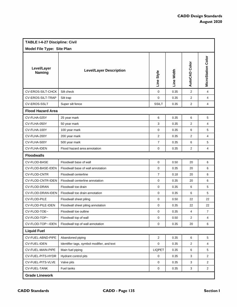
CADD Standards CADD - Page 135 Section I
CADD Design Standards
August 2020
TABLE I-4-27 Discipline: Civil
Model File Type: Site Plan
Level/Layer
Naming
Level/Layer Description
Lin
e S
tyle
Lin
e W
idth
Au
toC
AD
Co
lor
Mic
roS
tati
on
Co
lor
CV-EROS-SILT-CHCK Silt check 0 0.35 2 4
CV-EROS-SILT-TRAP Silt trap 0 0.35 2 4
CV-EROS-SSLT Super silt fence SSILT 0.35 2 4
Flood Hazard Area
CV-FLHA-025Y 25 year mark 6 0.35 6 5
CV-FLHA-050Y 50 year mark 3 0.35 2 4
CV-FLHA-100Y 100 year mark 0 0.35 6 5
CV-FLHA-200Y 200 year mark 2 0.35 2 4
CV-FLHA-500Y 500 year mark 7 0.35 6 5
CV-FLHA-IDEN Flood hazard area annotation 0 0.35 2 4
Floodwalls
CV-FLOD-BASE Floodwall base of wall 0 0.50 20 6
CV-FLOD-BASE-IDEN Floodwall base of wall annotation 0 0.35 20 6
CV-FLOD-CNTR Floodwall centerline 7 0.18 20 6
CV-FLOD-CNTR-IDEN Floodwall centerline annotation 0 0.35 20 6
CV-FLOD-DRAN Floodwall toe drain 0 0.35 6 5
CV-FLOD-DRAN-IDEN Floodwall toe drain annotation 0 0.35 6 5
CV-FLOD-PILE Floodwall sheet piling 0 0.50 22 22
CV-FLOD-PILE-IDEN Floodwall sheet piling annotation 0 0.35 22 22
CV-FLOD-TOE~ Floodwall toe outline 0 0.35 4 7
CV-FLOD-TOP~ Floodwall top of wall 0 0.50 2 4
CV-FLOD-TOP~-IDEN Floodwall top of wall annotation 0 0.35 20 6
Liquid Fuel
CV-FUEL-ABND-PIPE Abandoned piping 2 0.35 6 5
CV-FUEL-IDEN Identifier tags, symbol modifier, and text 0 0.35 2 4
CV-FUEL-MAIN-PIPE Main fuel piping LIQPET 0.35 6 5
CV-FUEL-PITS-HYDR Hydrant control pits 0 0.35 3 2
CV-FUEL-PITS-VLVE Valve pits 0 0.35 3 2
CV-FUEL-TANK Fuel tanks 0 0.35 3 2
Grade Linework
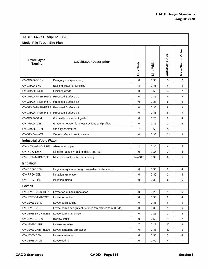
CADD Standards CADD - Page 136 Section I
CADD Design Standards
August 2020
TABLE I-4-27 Discipline: Civil
Model File Type: Site Plan
Level/Layer
Naming
Level/Layer Description
Lin
e S
tyle
Lin
e W
idth
Au
toC
AD
Co
lor
Mic
roS
tati
on
Co
lor
CV-GRAD-DSGN Design grade (proposed) 0 0.35 3 2
CV-GRAD-EXST Existing grade, ground line 3 0.35 6 5
CV-GRAD-FNSH Finished grade 0 0.50 4 7
CV-GRAD-FNSH-PRP1 Proposed Surface #1 0 0.35 8 9
CV-GRAD-FNSH-PRP2 Proposed Surface #2 0 0.35 8 9
CV-GRAD-FNSH-PRP3 Proposed Surface #3 0 0.35 8 9
CV-GRAD-FNSH-PRP4 Proposed Surface #4 0 0.35 8 9
CV-GRAD-GTXL Geotextile placement grade 0 0.25 2 4
CV-GRAD-IDEN Grade annotation for cross sections and profiles 0 0.35 2 4
CV-GRAD-SCLN Stability control line 7 0.50 5 1
CV-GRAD-WATR Water surface in section view 0 0.35 2 4
Industrial Waste Water
CV-INDW-ABND-PIPE Abandoned piping 2 0.35 6 5
CV-INDW-IDEN Identifier tags, symbol modifier, and text 0 0.35 2 4
CV-INDW-MAIN-PIPE Main industrial waste water piping IWASTE 0.35 6 5
Irrigation
CV-IRRG-EQPM Irrigation equipment (e.g., controllers, valves, etc.) 0 0.35 2 4
CV-IRRG-IDEN Irrigation annotation 0 0.35 2 4
CV-IRRG-PIPE Irrigation piping 0 0.35 6 5
Levees
CV-LEVE-BANK-IDEN Levee top of bank annotation 0 0.25 20 6
CV-LEVE-BANK-TOP Levee top of bank 0 0.35 2 4
CV-LEVE-BERM Levee berm outline 0 0.35 6 5
CV-LEVE-BNCH Levee bench design feature lines (breaklines form DTMs) 0 0.35 20 6
CV-LEVE-BNCH-IDEN Levee bench annotation 0 0.25 2 4
CV-LEVE-BRRW Borrow limits 0 0.50 4 7
CV-LEVE-CNTR Levee centerline 7 0.18 20 6
CV-LEVE-CNTR-IDEN Levee centerline annotation 0 0.35 20 6
CV-LEVE-IDEN Levee annotation 0 0.35 2 4
CV-LEVE-OTLN Levee outline 0 0.50 4 7
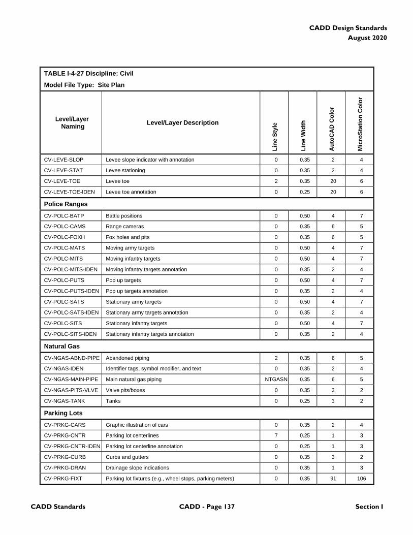
CADD Standards CADD - Page 137 Section I
CADD Design Standards
August 2020
TABLE I-4-27 Discipline: Civil
Model File Type: Site Plan
Level/Layer
Naming
Level/Layer Description
Lin
e S
tyle
Lin
e W
idth
Au
toC
AD
Co
lor
Mic
roS
tati
on
Co
lor
CV-LEVE-SLOP Levee slope indicator with annotation 0 0.35 2 4
CV-LEVE-STAT Levee stationing 0 0.35 2 4
CV-LEVE-TOE Levee toe 2 0.35 20 6
CV-LEVE-TOE-IDEN Levee toe annotation 0 0.25 20 6
Police Ranges
CV-POLC-BATP Battle positions 0 0.50 4 7
CV-POLC-CAMS Range cameras 0 0.35 6 5
CV-POLC-FOXH Fox holes and pits 0 0.35 6 5
CV-POLC-MATS Moving army targets 0 0.50 4 7
CV-POLC-MITS Moving infantry targets 0 0.50 4 7
CV-POLC-MITS-IDEN Moving infantry targets annotation 0 0.35 2 4
CV-POLC-PUTS Pop up targets 0 0.50 4 7
CV-POLC-PUTS-IDEN Pop up targets annotation 0 0.35 2 4
CV-POLC-SATS Stationary army targets 0 0.50 4 7
CV-POLC-SATS-IDEN Stationary army targets annotation 0 0.35 2 4
CV-POLC-SITS Stationary infantry targets 0 0.50 4 7
CV-POLC-SITS-IDEN Stationary infantry targets annotation 0 0.35 2 4
Natural Gas
CV-NGAS-ABND-PIPE Abandoned piping 2 0.35 6 5
CV-NGAS-IDEN Identifier tags, symbol modifier, and text 0 0.35 2 4
CV-NGAS-MAIN-PIPE Main natural gas piping NTGASN 0.35 6 5
CV-NGAS-PITS-VLVE Valve pits/boxes 0 0.35 3 2
CV-NGAS-TANK Tanks 0 0.25 3 2
Parking Lots
CV-PRKG-CARS Graphic illustration of cars 0 0.35 2 4
CV-PRKG-CNTR Parking lot centerlines 7 0.25 1 3
CV-PRKG-CNTR-IDEN Parking lot centerline annotation 0 0.25 1 3
CV-PRKG-CURB Curbs and gutters 0 0.35 3 2
CV-PRKG-DRAN Drainage slope indications 0 0.35 1 3
CV-PRKG-FIXT Parking lot fixtures (e.g., wheel stops, parking meters) 0 0.35 91 106
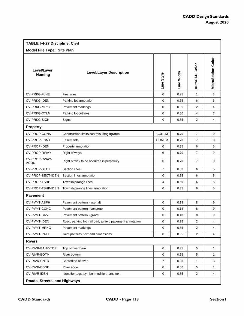
CADD Standards CADD - Page 138 Section I
CADD Design Standards
August 2020
TABLE I-4-27 Discipline: Civil
Model File Type: Site Plan
Level/Layer
Naming
Level/Layer Description
Lin
e S
tyle
Lin
e W
idth
Au
toC
AD
Co
lor
Mic
roS
tati
on
Co
lor
CV-PRKG-FLNE Fire lanes 0 0.25 1 3
CV-PRKG-IDEN Parking lot annotation 0 0.35 6 5
CV-PRKG-MRKG Pavement markings 0 0.35 2 4
CV-PRKG-OTLN Parking lot outlines 0 0.50 4 7
CV-PRKG-SIGN Signs 0 0.35 2 4
Property
CV-PROP-CONS Construction limits/controls, staging area CONLMT 0.70 7 0
CV-PROP-ESMT Easements CONEMT 0.70 7 0
CV-PROP-IDEN Property annotation 0 0.35 6 5
CV-PROP-RWAY Right of ways 6 0.70 7 0
CV-PROP-RWAY- ACQU
Right of way to be acquired in perpetuity
0
0.70
7
0
CV-PROP-SECT Section lines 7 0.50 6 5
CV-PROP-SECT-IDEN Section lines annotation 0 0.35 6 5
CV-PROP-TSHP Township/range lines 4 0.50 6 5
CV-PROP-TSHP-IDEN Township/range lines annotation 0 0.35 6 5
Pavement
CV-PVMT-ASPH Pavement pattern - asphalt 0 0.18 8 9
CV-PVMT-CONC Pavement pattern - concrete 0 0.18 8 9
CV-PVMT-GRVL Pavement pattern - gravel 0 0.18 8 9
CV-PVMT-IDEN Road, parking lot, railroad, airfield pavement annotation 0 0.25 2 4
CV-PVMT-MRKG Pavement markings 0 0.35 2 4
CV-PVMT-PATT Joint patterns, text and dimensions 0 0.35 2 4
Rivers
CV-RIVR-BANK-TOP Top of river bank 0 0.35 5 1
CV-RIVR-BOTM River bottom 0 0.35 5 1
CV-RIVR-CNTR Centerline of river 7 0.25 1 3
CV-RIVR-EDGE River edge 0 0.50 5 1
CV-RIVR-IDEN Identifier tags, symbol modifiers, and text 0 0.35 2 4
Roads, Streets, and Highways
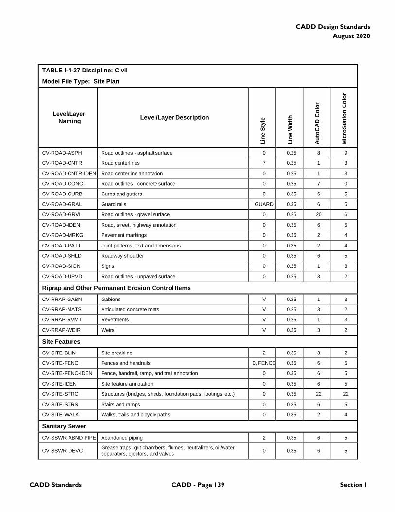
CADD Standards CADD - Page 139 Section I
CADD Design Standards
August 2020
TABLE I-4-27 Discipline: Civil
Model File Type: Site Plan
Level/Layer
Naming
Level/Layer Description
Lin
e S
tyle
Lin
e W
idth
Au
toC
AD
Co
lor
Mic
roS
tati
on
Co
lor
CV-ROAD-ASPH Road outlines - asphalt surface 0 0.25 8 9
CV-ROAD-CNTR Road centerlines 7 0.25 1 3
CV-ROAD-CNTR-IDEN Road centerline annotation 0 0.25 1 3
CV-ROAD-CONC Road outlines - concrete surface 0 0.25 7 0
CV-ROAD-CURB Curbs and gutters 0 0.35 6 5
CV-ROAD-GRAL Guard rails GUARD 0.35 6 5
CV-ROAD-GRVL Road outlines - gravel surface 0 0.25 20 6
CV-ROAD-IDEN Road, street, highway annotation 0 0.35 6 5
CV-ROAD-MRKG Pavement markings 0 0.35 2 4
CV-ROAD-PATT Joint patterns, text and dimensions 0 0.35 2 4
CV-ROAD-SHLD Roadway shoulder 0 0.35 6 5
CV-ROAD-SIGN Signs 0 0.25 1 3
CV-ROAD-UPVD Road outlines - unpaved surface 0 0.25 3 2
Riprap and Other Permanent Erosion Control Items
CV-RRAP-GABN Gabions V 0.25 1 3
CV-RRAP-MATS Articulated concrete mats V 0.25 3 2
CV-RRAP-RVMT Revetments V 0.25 1 3
CV-RRAP-WEIR Weirs V 0.25 3 2
Site Features
CV-SITE-BLIN Site breakline 2 0.35 3 2
CV-SITE-FENC Fences and handrails 0, FENCE 0.35 6 5
CV-SITE-FENC-IDEN Fence, handrail, ramp, and trail annotation 0 0.35 6 5
CV-SITE-IDEN Site feature annotation 0 0.35 6 5
CV-SITE-STRC Structures (bridges, sheds, foundation pads, footings, etc.) 0 0.35 22 22
CV-SITE-STRS Stairs and ramps 0 0.35 6 5
CV-SITE-WALK Walks, trails and bicycle paths 0 0.35 2 4
Sanitary Sewer
CV-SSWR-ABND-PIPE Abandoned piping 2 0.35 6 5
CV-SSWR-DEVC Grease traps, grit chambers, flumes, neutralizers, oil/water separators, ejectors, and valves
0
0.35
6
5
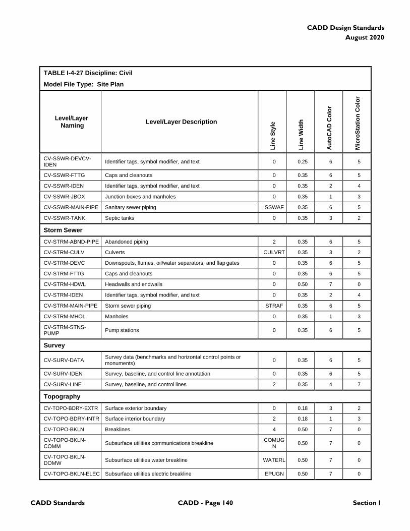
CADD Standards CADD - Page 140 Section I
CADD Design Standards
August 2020
TABLE I-4-27 Discipline: Civil
Model File Type: Site Plan
Level/Layer
Naming
Level/Layer Description
Lin
e S
tyle
Lin
e W
idth
Au
toC
AD
Co
lor
Mic
roS
tati
on
Co
lor
CV-SSWR-DEVCV- IDEN
Identifier tags, symbol modifier, and text
0
0.25
6
5
CV-SSWR-FTTG Caps and cleanouts 0 0.35 6 5
CV-SSWR-IDEN Identifier tags, symbol modifier, and text 0 0.35 2 4
CV-SSWR-JBOX Junction boxes and manholes 0 0.35 1 3
CV-SSWR-MAIN-PIPE Sanitary sewer piping SSWAF 0.35 6 5
CV-SSWR-TANK Septic tanks 0 0.35 3 2
Storm Sewer
CV-STRM-ABND-PIPE Abandoned piping 2 0.35 6 5
CV-STRM-CULV Culverts CULVRT 0.35 3 2
CV-STRM-DEVC Downspouts, flumes, oil/water separators, and flap gates 0 0.35 6 5
CV-STRM-FTTG Caps and cleanouts 0 0.35 6 5
CV-STRM-HDWL Headwalls and endwalls 0 0.50 7 0
CV-STRM-IDEN Identifier tags, symbol modifier, and text 0 0.35 2 4
CV-STRM-MAIN-PIPE Storm sewer piping STRAF 0.35 6 5
CV-STRM-MHOL Manholes 0 0.35 1 3
CV-STRM-STNS- PUMP
Pump stations
0
0.35
6
5
Survey
CV-SURV-DATA Survey data (benchmarks and horizontal control points or monuments)
0
0.35
6
5
CV-SURV-IDEN Survey, baseline, and control line annotation 0 0.35 6 5
CV-SURV-LINE Survey, baseline, and control lines 2 0.35 4 7
Topography
CV-TOPO-BDRY-EXTR Surface exterior boundary 0 0.18 3 2
CV-TOPO-BDRY-INTR Surface interior boundary 2 0.18 1 3
CV-TOPO-BKLN Breaklines 4 0.50 7 0
CV-TOPO-BKLN- COMM
Subsurface utilities communications breakline COMUG
N
0.50
7
0
CV-TOPO-BKLN- DOMW
Subsurface utilities water breakline
WATERL
0.50
7
0
CV-TOPO-BKLN-ELEC Subsurface utilities electric breakline EPUGN 0.50 7 0
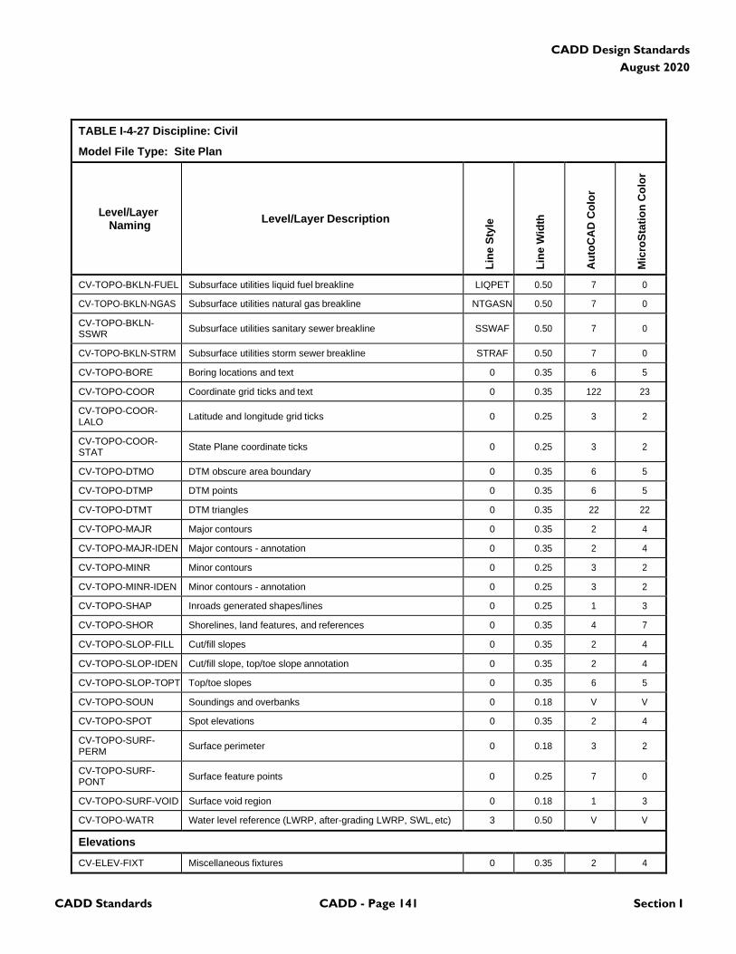
CADD Standards CADD - Page 141 Section I
CADD Design Standards
August 2020
TABLE I-4-27 Discipline: Civil
Model File Type: Site Plan
Level/Layer
Naming
Level/Layer Description
Lin
e S
tyle
Lin
e W
idth
Au
toC
AD
Co
lor
Mic
roS
tati
on
Co
lor
CV-TOPO-BKLN-FUEL Subsurface utilities liquid fuel breakline LIQPET 0.50 7 0
CV-TOPO-BKLN-NGAS Subsurface utilities natural gas breakline NTGASN 0.50 7 0
CV-TOPO-BKLN- SSWR
Subsurface utilities sanitary sewer breakline
SSWAF
0.50
7
0
CV-TOPO-BKLN-STRM Subsurface utilities storm sewer breakline STRAF 0.50 7 0
CV-TOPO-BORE Boring locations and text 0 0.35 6 5
CV-TOPO-COOR Coordinate grid ticks and text 0 0.35 122 23
CV-TOPO-COOR- LALO
Latitude and longitude grid ticks
0
0.25
3
2
CV-TOPO-COOR- STAT
State Plane coordinate ticks
0
0.25
3
2
CV-TOPO-DTMO DTM obscure area boundary 0 0.35 6 5
CV-TOPO-DTMP DTM points 0 0.35 6 5
CV-TOPO-DTMT DTM triangles 0 0.35 22 22
CV-TOPO-MAJR Major contours 0 0.35 2 4
CV-TOPO-MAJR-IDEN Major contours - annotation 0 0.35 2 4
CV-TOPO-MINR Minor contours 0 0.25 3 2
CV-TOPO-MINR-IDEN Minor contours - annotation 0 0.25 3 2
CV-TOPO-SHAP Inroads generated shapes/lines 0 0.25 1 3
CV-TOPO-SHOR Shorelines, land features, and references 0 0.35 4 7
CV-TOPO-SLOP-FILL Cut/fill slopes 0 0.35 2 4
CV-TOPO-SLOP-IDEN Cut/fill slope, top/toe slope annotation 0 0.35 2 4
CV-TOPO-SLOP-TOPT Top/toe slopes 0 0.35 6 5
CV-TOPO-SOUN Soundings and overbanks 0 0.18 V V
CV-TOPO-SPOT Spot elevations 0 0.35 2 4
CV-TOPO-SURF- PERM
Surface perimeter
0
0.18
3
2
CV-TOPO-SURF- PONT
Surface feature points
0
0.25
7
0
CV-TOPO-SURF-VOID Surface void region 0 0.18 1 3
CV-TOPO-WATR Water level reference (LWRP, after-grading LWRP, SWL, etc) 3 0.50 V V
Elevations
CV-ELEV-FIXT Miscellaneous fixtures 0 0.35 2 4
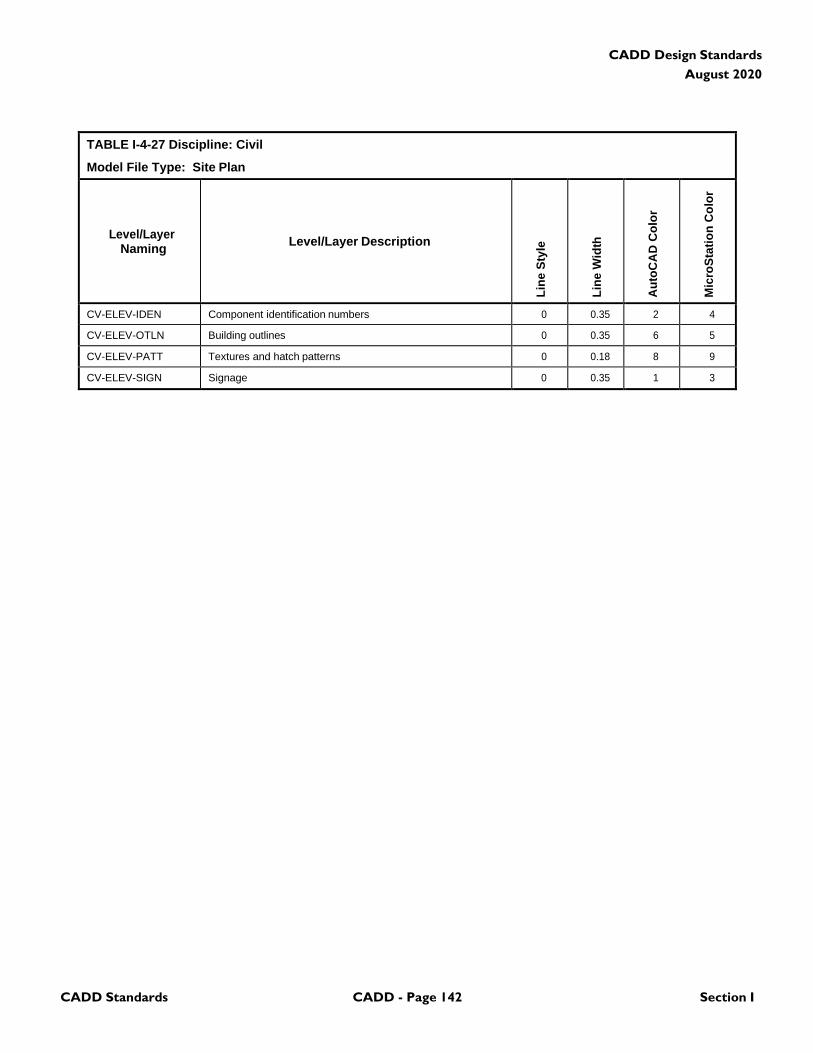
CADD Standards CADD - Page 142 Section I
CADD Design Standards
August 2020
TABLE I-4-27 Discipline: Civil
Model File Type: Site Plan
Level/Layer
Naming
Level/Layer Description
Lin
e S
tyle
Lin
e W
idth
Au
toC
AD
Co
lor
Mic
roS
tati
on
Co
lor
CV-ELEV-IDEN Component identification numbers 0 0.35 2 4
CV-ELEV-OTLN Building outlines 0 0.35 6 5
CV-ELEV-PATT Textures and hatch patterns 0 0.18 8 9
CV-ELEV-SIGN Signage 0 0.35 1 3
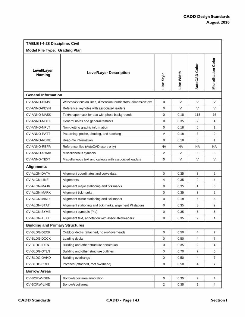
CADD Standards CADD - Page 143 Section I
CADD Design Standards
August 2020
TABLE I-4-28 Discipline: Civil
Model File Type: Grading Plan
Level/Layer
Naming
Level/Layer Description
Lin
e S
tyle
Lin
e W
idth
Au
toC
AD
Co
lor
Mic
roS
tati
on
Co
lor
General Information
CV-ANNO-DIMS Witness/extension lines, dimension terminators, dimension text 0 V V V
CV-ANNO-KEYN Reference keynotes with associated leaders 0 V V V
CV-ANNO-MASK Text/shape mask for use with photo backgrounds 0 0.18 113 16
CV-ANNO-NOTE General notes and general remarks 0 0.35 2 4
CV-ANNO-NPLT Non-plotting graphic information 0 0.18 5 1
CV-ANNO-PATT Patterning, poche, shading, and hatching V 0.18 8 9
CV-ANNO-RDME Read-me information 0 0.18 5 1
CV-ANNO-REFR Reference files (AutoCAD users only) NA NA NA NA
CV-ANNO-SYMB Miscellaneous symbols V V 6 5
CV-ANNO-TEXT Miscellaneous text and callouts with associated leaders 0 V V V
Alignments
CV-ALGN-DATA Alignment coordinates and curve data 0 0.35 3 2
CV-ALGN-LINE Alignments 4 0.35 2 4
CV-ALGN-MAJR Alignment major stationing and tick marks 0 0.35 1 3
CV-ALGN-MARK Alignment tick marks 0 0.35 3 2
CV-ALGN-MINR Alignment minor stationing and tick marks 0 0.18 6 5
CV-ALGN-STAT Alignment stationing and tick marks, alignment PI stations 0 0.35 3 2
CV-ALGN-SYMB Alignment symbols (PIs) 0 0.35 6 5
CV-ALGN-TEXT Alignment text, annotation with associated leaders 0 0.35 2 4
Building and Primary Structures
CV-BLDG-DECK Outdoor decks (attached, no roof overhead) 0 0.50 4 7
CV-BLDG-DOCK Loading docks 0 0.50 4 7
CV-BLDG-IDEN Building and other structure annotation 0 0.35 2 4
CV-BLDG-OTLN Building and other structure outlines 0 0.70 7 0
CV-BLDG-OVHD Building overhangs 0 0.50 4 7
CV-BLDG-PRCH Porches (attached, roof overhead) 0 0.50 4 7
Borrow Areas
CV-BORW-IDEN Borrow/spoil area annotation 0 0.35 2 4
CV-BORW-LINE Borrow/spoil area 2 0.35 2 4
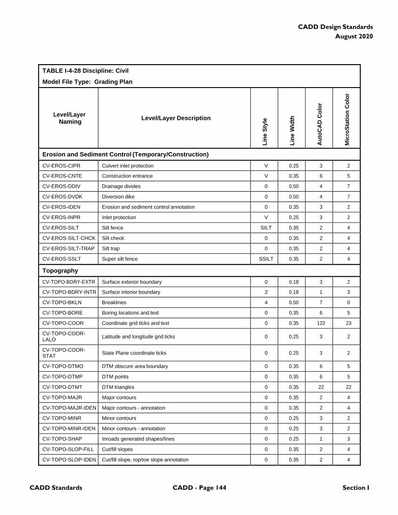
CADD Standards CADD - Page 144 Section I
CADD Design Standards
August 2020
TABLE I-4-28 Discipline: Civil
Model File Type: Grading Plan
Level/Layer
Naming
Level/Layer Description
Lin
e S
tyle
Lin
e W
idth
Au
toC
AD
Co
lor
Mic
roS
tati
on
Co
lor
Erosion and Sediment Control (Temporary/Construction)
CV-EROS-CIPR Culvert inlet protection V 0.25 3 2
CV-EROS-CNTE Construction entrance V 0.35 6 5
CV-EROS-DDIV Drainage divides 0 0.50 4 7
CV-EROS-DVDK Diversion dike 0 0.50 4 7
CV-EROS-IDEN Erosion and sediment control annotation 0 0.35 3 2
CV-EROS-INPR Inlet protection V 0.25 3 2
CV-EROS-SILT Silt fence SILT 0.35 2 4
CV-EROS-SILT-CHCK Silt check 0 0.35 2 4
CV-EROS-SILT-TRAP Silt trap 0 0.35 2 4
CV-EROS-SSLT Super silt fence SSILT 0.35 2 4
Topography
CV-TOPO-BDRY-EXTR Surface exterior boundary 0 0.18 3 2
CV-TOPO-BDRY-INTR Surface interior boundary 2 0.18 1 3
CV-TOPO-BKLN Breaklines 4 0.50 7 0
CV-TOPO-BORE Boring locations and text 0 0.35 6 5
CV-TOPO-COOR Coordinate grid ticks and text 0 0.35 122 23
CV-TOPO-COOR- LALO
Latitude and longitude grid ticks
0
0.25
3
2
CV-TOPO-COOR- STAT
State Plane coordinate ticks
0
0.25
3
2
CV-TOPO-DTMO DTM obscure area boundary 0 0.35 6 5
CV-TOPO-DTMP DTM points 0 0.35 6 5
CV-TOPO-DTMT DTM triangles 0 0.35 22 22
CV-TOPO-MAJR Major contours 0 0.35 2 4
CV-TOPO-MAJR-IDEN Major contours - annotation 0 0.35 2 4
CV-TOPO-MINR Minor contours 0 0.25 3 2
CV-TOPO-MINR-IDEN Minor contours - annotation 0 0.25 3 2
CV-TOPO-SHAP Inroads generated shapes/lines 0 0.25 1 3
CV-TOPO-SLOP-FILL Cut/fill slopes 0 0.35 2 4
CV-TOPO-SLOP-IDEN Cut/fill slope, top/toe slope annotation 0 0.35 2 4
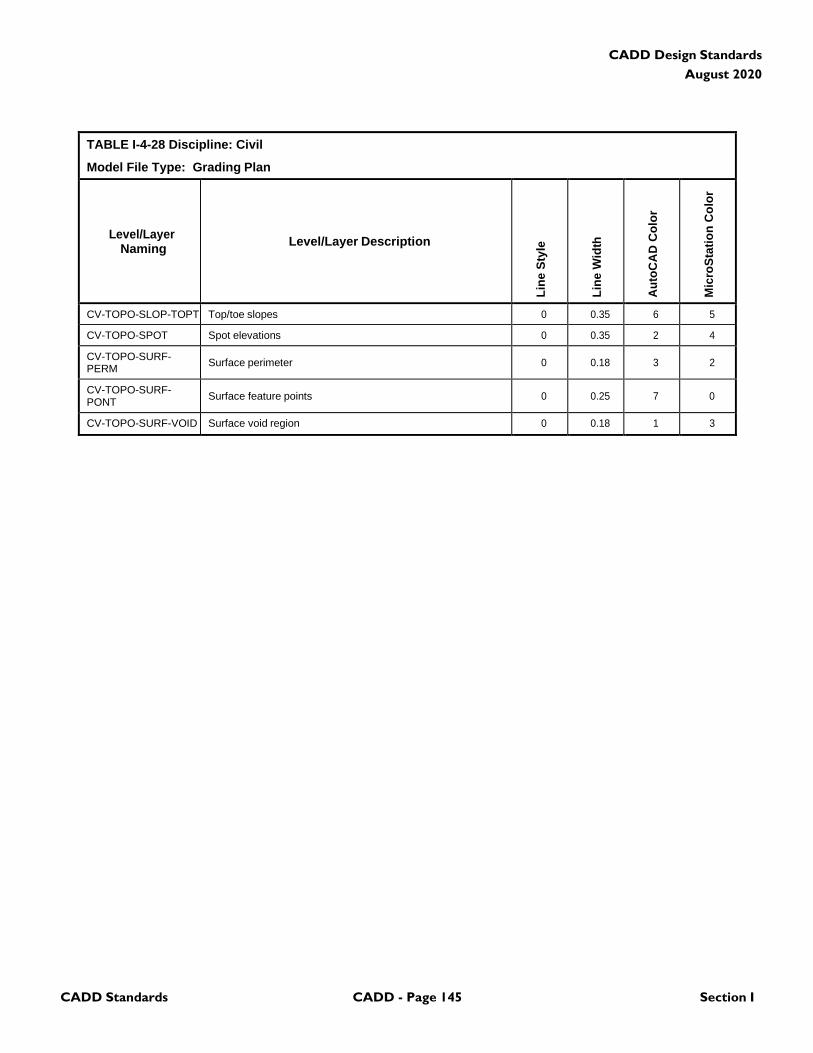
CADD Standards CADD - Page 145 Section I
CADD Design Standards
August 2020
TABLE I-4-28 Discipline: Civil
Model File Type: Grading Plan
Level/Layer
Naming
Level/Layer Description
Lin
e S
tyle
Lin
e W
idth
Au
toC
AD
Co
lor
Mic
roS
tati
on
Co
lor
CV-TOPO-SLOP-TOPT Top/toe slopes 0 0.35 6 5
CV-TOPO-SPOT Spot elevations 0 0.35 2 4
CV-TOPO-SURF- PERM
Surface perimeter
0
0.18
3
2
CV-TOPO-SURF- PONT
Surface feature points
0
0.25
7
0
CV-TOPO-SURF-VOID Surface void region 0 0.18 1 3
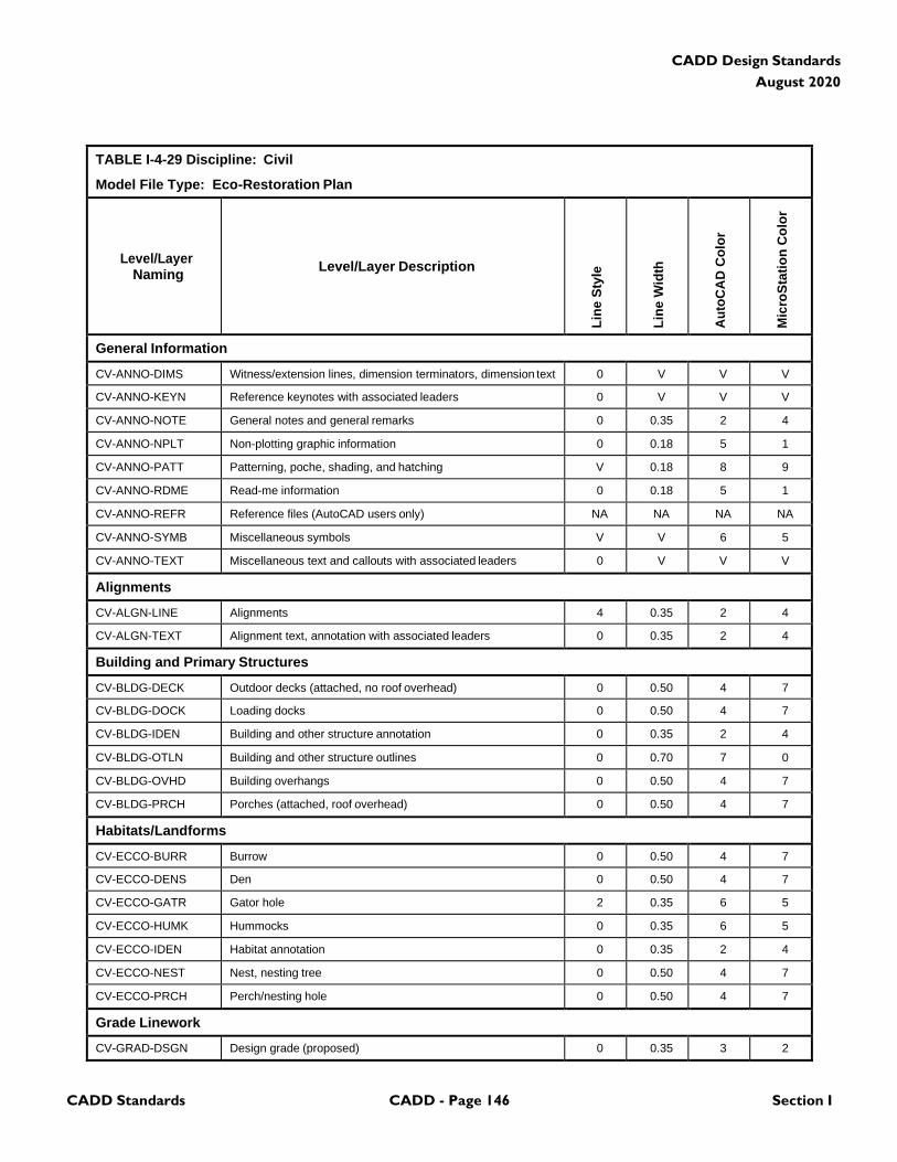
CADD Standards CADD - Page 146 Section I
CADD Design Standards
August 2020
TABLE I-4-29 Discipline: Civil
Model File Type: Eco-Restoration Plan
Level/Layer
Naming
Level/Layer Description
Lin
e S
tyle
Lin
e W
idth
Au
toC
AD
Co
lor
Mic
roS
tati
on
Co
lor
General Information
CV-ANNO-DIMS Witness/extension lines, dimension terminators, dimension text 0 V V V
CV-ANNO-KEYN Reference keynotes with associated leaders 0 V V V
CV-ANNO-NOTE General notes and general remarks 0 0.35 2 4
CV-ANNO-NPLT Non-plotting graphic information 0 0.18 5 1
CV-ANNO-PATT Patterning, poche, shading, and hatching V 0.18 8 9
CV-ANNO-RDME Read-me information 0 0.18 5 1
CV-ANNO-REFR Reference files (AutoCAD users only) NA NA NA NA
CV-ANNO-SYMB Miscellaneous symbols V V 6 5
CV-ANNO-TEXT Miscellaneous text and callouts with associated leaders 0 V V V
Alignments
CV-ALGN-LINE Alignments 4 0.35 2 4
CV-ALGN-TEXT Alignment text, annotation with associated leaders 0 0.35 2 4
Building and Primary Structures
CV-BLDG-DECK Outdoor decks (attached, no roof overhead) 0 0.50 4 7
CV-BLDG-DOCK Loading docks 0 0.50 4 7
CV-BLDG-IDEN Building and other structure annotation 0 0.35 2 4
CV-BLDG-OTLN Building and other structure outlines 0 0.70 7 0
CV-BLDG-OVHD Building overhangs 0 0.50 4 7
CV-BLDG-PRCH Porches (attached, roof overhead) 0 0.50 4 7
Habitats/Landforms
CV-ECCO-BURR Burrow 0 0.50 4 7
CV-ECCO-DENS Den 0 0.50 4 7
CV-ECCO-GATR Gator hole 2 0.35 6 5
CV-ECCO-HUMK Hummocks 0 0.35 6 5
CV-ECCO-IDEN Habitat annotation 0 0.35 2 4
CV-ECCO-NEST Nest, nesting tree 0 0.50 4 7
CV-ECCO-PRCH Perch/nesting hole 0 0.50 4 7
Grade Linework
CV-GRAD-DSGN Design grade (proposed) 0 0.35 3 2
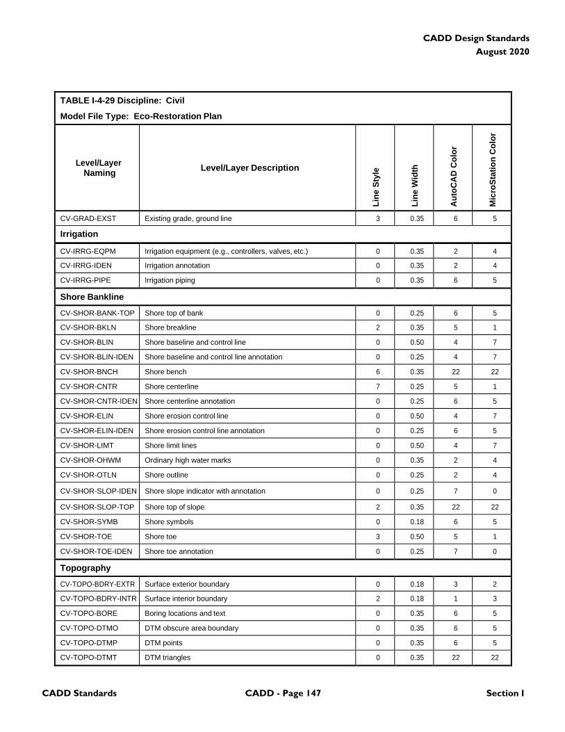
CADD Standards CADD - Page 147 Section I
CADD Design Standards
August 2020
TABLE I-4-29 Discipline: Civil
Model File Type: Eco-Restoration Plan
Level/Layer
Naming
Level/Layer Description
Lin
e S
tyle
Lin
e W
idth
Au
toC
AD
Co
lor
Mic
roS
tati
on
Co
lor
CV-GRAD-EXST Existing grade, ground line 3 0.35 6 5
Irrigation
CV-IRRG-EQPM Irrigation equipment (e.g., controllers, valves, etc.) 0 0.35 2 4
CV-IRRG-IDEN Irrigation annotation 0 0.35 2 4
CV-IRRG-PIPE Irrigation piping 0 0.35 6 5
Shore Bankline
CV-SHOR-BANK-TOP Shore top of bank 0 0.25 6 5
CV-SHOR-BKLN Shore breakline 2 0.35 5 1
CV-SHOR-BLIN Shore baseline and control line 0 0.50 4 7
CV-SHOR-BLIN-IDEN Shore baseline and control line annotation 0 0.25 4 7
CV-SHOR-BNCH Shore bench 6 0.35 22 22
CV-SHOR-CNTR Shore centerline 7 0.25 5 1
CV-SHOR-CNTR-IDEN Shore centerline annotation 0 0.25 6 5
CV-SHOR-ELIN Shore erosion control line 0 0.50 4 7
CV-SHOR-ELIN-IDEN Shore erosion control line annotation 0 0.25 6 5
CV-SHOR-LIMT Shore limit lines 0 0.50 4 7
CV-SHOR-OHWM Ordinary high water marks 0 0.35 2 4
CV-SHOR-OTLN Shore outline 0 0.25 2 4
CV-SHOR-SLOP-IDEN Shore slope indicator with annotation 0 0.25 7 0
CV-SHOR-SLOP-TOP Shore top of slope 2 0.35 22 22
CV-SHOR-SYMB Shore symbols 0 0.18 6 5
CV-SHOR-TOE Shore toe 3 0.50 5 1
CV-SHOR-TOE-IDEN Shore toe annotation 0 0.25 7 0
Topography
CV-TOPO-BDRY-EXTR Surface exterior boundary 0 0.18 3 2
CV-TOPO-BDRY-INTR Surface interior boundary 2 0.18 1 3
CV-TOPO-BORE Boring locations and text 0 0.35 6 5
CV-TOPO-DTMO DTM obscure area boundary 0 0.35 6 5
CV-TOPO-DTMP DTM points 0 0.35 6 5
CV-TOPO-DTMT DTM triangles 0 0.35 22 22
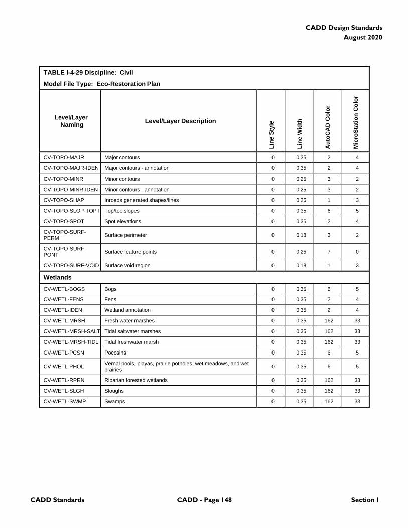
CADD Standards CADD - Page 148 Section I
CADD Design Standards
August 2020
TABLE I-4-29 Discipline: Civil
Model File Type: Eco-Restoration Plan
Level/Layer
Naming
Level/Layer Description
Lin
e S
tyle
Lin
e W
idth
Au
toC
AD
Co
lor
Mic
roS
tati
on
Co
lor
CV-TOPO-MAJR Major contours 0 0.35 2 4
CV-TOPO-MAJR-IDEN Major contours - annotation 0 0.35 2 4
CV-TOPO-MINR Minor contours 0 0.25 3 2
CV-TOPO-MINR-IDEN Minor contours - annotation 0 0.25 3 2
CV-TOPO-SHAP Inroads generated shapes/lines 0 0.25 1 3
CV-TOPO-SLOP-TOPT Top/toe slopes 0 0.35 6 5
CV-TOPO-SPOT Spot elevations 0 0.35 2 4
CV-TOPO-SURF- PERM
Surface perimeter
0
0.18
3
2
CV-TOPO-SURF- PONT
Surface feature points
0
0.25
7
0
CV-TOPO-SURF-VOID Surface void region 0 0.18 1 3
Wetlands
CV-WETL-BOGS Bogs 0 0.35 6 5
CV-WETL-FENS Fens 0 0.35 2 4
CV-WETL-IDEN Wetland annotation 0 0.35 2 4
CV-WETL-MRSH Fresh water marshes 0 0.35 162 33
CV-WETL-MRSH-SALT Tidal saltwater marshes 0 0.35 162 33
CV-WETL-MRSH-TIDL Tidal freshwater marsh 0 0.35 162 33
CV-WETL-PCSN Pocosins 0 0.35 6 5
CV-WETL-PHOL Vernal pools, playas, prairie potholes, wet meadows, and wet prairies
0
0.35
6
5
CV-WETL-RPRN Riparian forested wetlands 0 0.35 162 33
CV-WETL-SLGH Sloughs 0 0.35 162 33
CV-WETL-SWMP Swamps 0 0.35 162 33
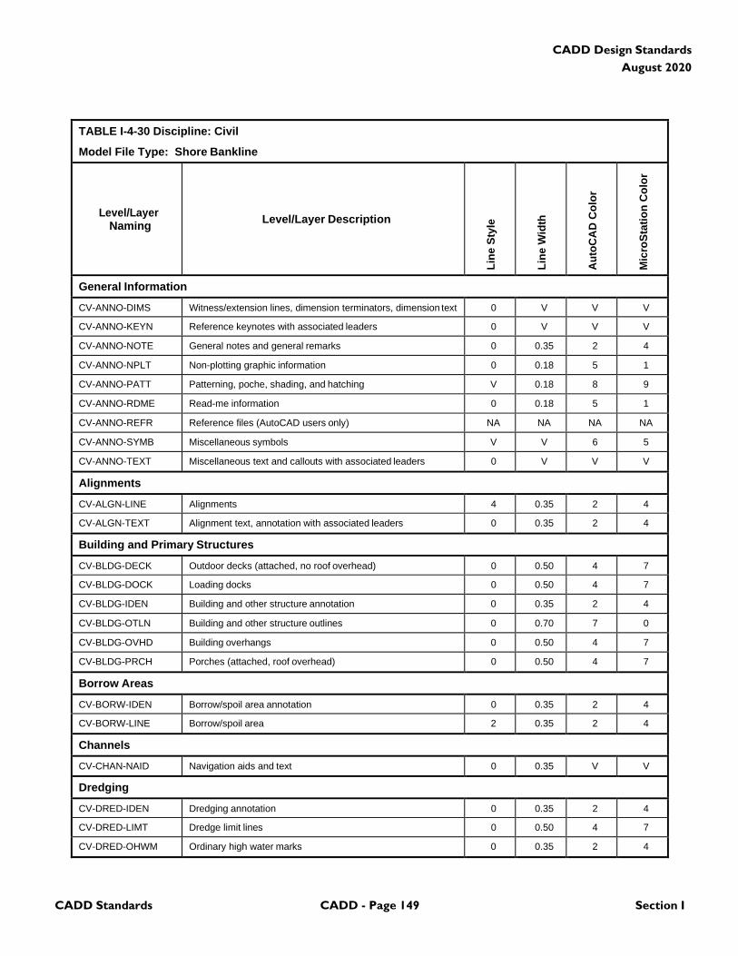
CADD Standards CADD - Page 149 Section I
CADD Design Standards
August 2020
TABLE I-4-30 Discipline: Civil
Model File Type: Shore Bankline
Level/Layer
Naming
Level/Layer Description
Lin
e S
tyle
Lin
e W
idth
Au
toC
AD
Co
lor
Mic
roS
tati
on
Co
lor
General Information
CV-ANNO-DIMS Witness/extension lines, dimension terminators, dimension text 0 V V V
CV-ANNO-KEYN Reference keynotes with associated leaders 0 V V V
CV-ANNO-NOTE General notes and general remarks 0 0.35 2 4
CV-ANNO-NPLT Non-plotting graphic information 0 0.18 5 1
CV-ANNO-PATT Patterning, poche, shading, and hatching V 0.18 8 9
CV-ANNO-RDME Read-me information 0 0.18 5 1
CV-ANNO-REFR Reference files (AutoCAD users only) NA NA NA NA
CV-ANNO-SYMB Miscellaneous symbols V V 6 5
CV-ANNO-TEXT Miscellaneous text and callouts with associated leaders 0 V V V
Alignments
CV-ALGN-LINE Alignments 4 0.35 2 4
CV-ALGN-TEXT Alignment text, annotation with associated leaders 0 0.35 2 4
Building and Primary Structures
CV-BLDG-DECK Outdoor decks (attached, no roof overhead) 0 0.50 4 7
CV-BLDG-DOCK Loading docks 0 0.50 4 7
CV-BLDG-IDEN Building and other structure annotation 0 0.35 2 4
CV-BLDG-OTLN Building and other structure outlines 0 0.70 7 0
CV-BLDG-OVHD Building overhangs 0 0.50 4 7
CV-BLDG-PRCH Porches (attached, roof overhead) 0 0.50 4 7
Borrow Areas
CV-BORW-IDEN Borrow/spoil area annotation 0 0.35 2 4
CV-BORW-LINE Borrow/spoil area 2 0.35 2 4
Channels
CV-CHAN-NAID Navigation aids and text 0 0.35 V V
Dredging
CV-DRED-IDEN Dredging annotation 0 0.35 2 4
CV-DRED-LIMT Dredge limit lines 0 0.50 4 7
CV-DRED-OHWM Ordinary high water marks 0 0.35 2 4
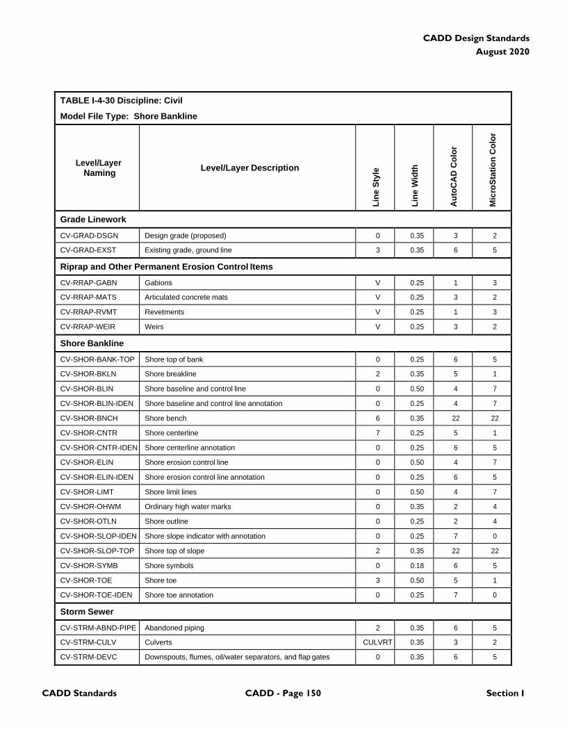
CADD Standards CADD - Page 150 Section I
CADD Design Standards
August 2020
TABLE I-4-30 Discipline: Civil
Model File Type: Shore Bankline
Level/Layer
Naming
Level/Layer Description
Lin
e S
tyle
Lin
e W
idth
Au
toC
AD
Co
lor
Mic
roS
tati
on
Co
lor
Grade Linework
CV-GRAD-DSGN Design grade (proposed) 0 0.35 3 2
CV-GRAD-EXST Existing grade, ground line 3 0.35 6 5
Riprap and Other Permanent Erosion Control Items
CV-RRAP-GABN Gabions V 0.25 1 3
CV-RRAP-MATS Articulated concrete mats V 0.25 3 2
CV-RRAP-RVMT Revetments V 0.25 1 3
CV-RRAP-WEIR Weirs V 0.25 3 2
Shore Bankline
CV-SHOR-BANK-TOP Shore top of bank 0 0.25 6 5
CV-SHOR-BKLN Shore breakline 2 0.35 5 1
CV-SHOR-BLIN Shore baseline and control line 0 0.50 4 7
CV-SHOR-BLIN-IDEN Shore baseline and control line annotation 0 0.25 4 7
CV-SHOR-BNCH Shore bench 6 0.35 22 22
CV-SHOR-CNTR Shore centerline 7 0.25 5 1
CV-SHOR-CNTR-IDEN Shore centerline annotation 0 0.25 6 5
CV-SHOR-ELIN Shore erosion control line 0 0.50 4 7
CV-SHOR-ELIN-IDEN Shore erosion control line annotation 0 0.25 6 5
CV-SHOR-LIMT Shore limit lines 0 0.50 4 7
CV-SHOR-OHWM Ordinary high water marks 0 0.35 2 4
CV-SHOR-OTLN Shore outline 0 0.25 2 4
CV-SHOR-SLOP-IDEN Shore slope indicator with annotation 0 0.25 7 0
CV-SHOR-SLOP-TOP Shore top of slope 2 0.35 22 22
CV-SHOR-SYMB Shore symbols 0 0.18 6 5
CV-SHOR-TOE Shore toe 3 0.50 5 1
CV-SHOR-TOE-IDEN Shore toe annotation 0 0.25 7 0
Storm Sewer
CV-STRM-ABND-PIPE Abandoned piping 2 0.35 6 5
CV-STRM-CULV Culverts CULVRT 0.35 3 2
CV-STRM-DEVC Downspouts, flumes, oil/water separators, and flap gates 0 0.35 6 5
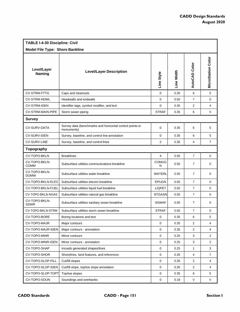
CADD Standards CADD - Page 151 Section I
CADD Design Standards
August 2020
TABLE I-4-30 Discipline: Civil
Model File Type: Shore Bankline
Level/Layer
Naming
Level/Layer Description
Lin
e S
tyle
Lin
e W
idth
Au
toC
AD
Co
lor
Mic
roS
tati
on
Co
lor
CV-STRM-FTTG Caps and cleanouts 0 0.35 6 5
CV-STRM-HDWL Headwalls and endwalls 0 0.50 7 0
CV-STRM-IDEN Identifier tags, symbol modifier, and text 0 0.35 2 4
CV-STRM-MAIN-PIPE Storm sewer piping STRAF 0.35 6 5
Survey
CV-SURV-DATA Survey data (benchmarks and horizontal control points or monuments)
0
0.35
6
5
CV-SURV-IDEN Survey, baseline, and control line annotation 0 0.35 6 5
CV-SURV-LINE Survey, baseline, and control lines 2 0.35 4 7
Topography
CV-TOPO-BKLN Breaklines 4 0.50 7 0
CV-TOPO-BKLN- COMM
Subsurface utilities communications breakline COMUG
N
0.50
7
0
CV-TOPO-BKLN- DOMW
Subsurface utilities water breakline
WATERL
0.50
7
0
CV-TOPO-BKLN-ELEC Subsurface utilities electric breakline EPUGN 0.50 7 0
CV-TOPO-BKLN-FUEL Subsurface utilities liquid fuel breakline LIQPET 0.50 7 0
CV-TOPO-BKLN-NGAS Subsurface utilities natural gas breakline NTGASN 0.50 7 0
CV-TOPO-BKLN- SSWR
Subsurface utilities sanitary sewer breakline
SSWAF
0.50
7
0
CV-TOPO-BKLN-STRM Subsurface utilities storm sewer breakline STRAF 0.50 7 0
CV-TOPO-BORE Boring locations and text 0 0.35 6 5
CV-TOPO-MAJR Major contours 0 0.35 2 4
CV-TOPO-MAJR-IDEN Major contours - annotation 0 0.35 2 4
CV-TOPO-MINR Minor contours 0 0.25 3 2
CV-TOPO-MINR-IDEN Minor contours - annotation 0 0.25 3 2
CV-TOPO-SHAP Inroads generated shapes/lines 0 0.25 1 3
CV-TOPO-SHOR Shorelines, land features, and references 0 0.35 4 7
CV-TOPO-SLOP-FILL Cut/fill slopes 0 0.35 2 4
CV-TOPO-SLOP-IDEN Cut/fill slope, top/toe slope annotation 0 0.35 2 4
CV-TOPO-SLOP-TOPT Top/toe slopes 0 0.35 6 5
CV-TOPO-SOUN Soundings and overbanks 0 0.18 V V
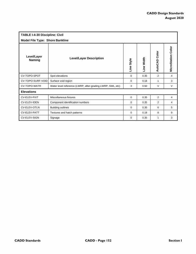
CADD Standards CADD - Page 152 Section I
CADD Design Standards
August 2020
TABLE I-4-30 Discipline: Civil
Model File Type: Shore Bankline
Level/Layer
Naming
Level/Layer Description
Lin
e S
tyle
Lin
e W
idth
Au
toC
AD
Co
lor
Mic
roS
tati
on
Co
lor
CV-TOPO-SPOT Spot elevations 0 0.35 2 4
CV-TOPO-SURF-VOID Surface void region 0 0.18 1 3
CV-TOPO-WATR Water level reference (LWRP, after-grading LWRP, SWL, etc) 3 0.50 V V
Elevations
CV-ELEV-FIXT Miscellaneous fixtures 0 0.35 2 4
CV-ELEV-IDEN Component identification numbers 0 0.35 2 4
CV-ELEV-OTLN Building outlines 0 0.35 6 5
CV-ELEV-PATT Textures and hatch patterns 0 0.18 8 9
CV-ELEV-SIGN Signage 0 0.35 1 3
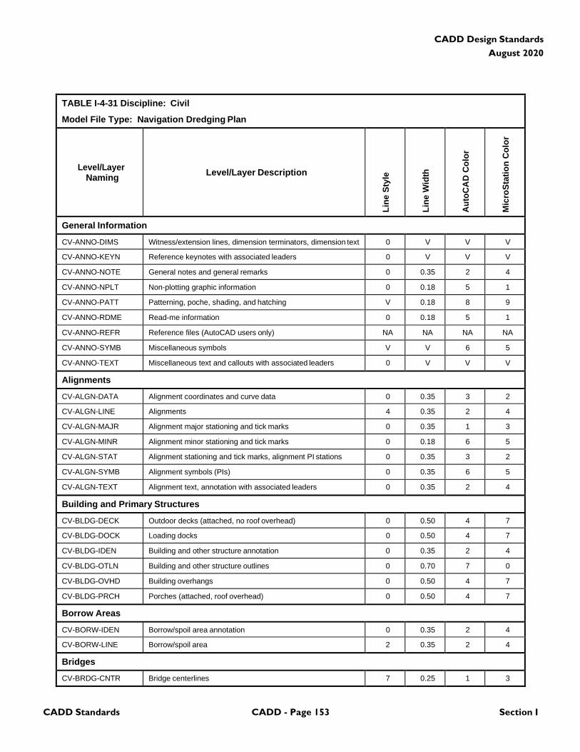
CADD Standards CADD - Page 153 Section I
CADD Design Standards
August 2020
TABLE I-4-31 Discipline: Civil
Model File Type: Navigation Dredging Plan
Level/Layer
Naming
Level/Layer Description
Lin
e S
tyle
Lin
e W
idth
Au
toC
AD
Co
lor
Mic
roS
tati
on
Co
lor
General Information
CV-ANNO-DIMS Witness/extension lines, dimension terminators, dimension text 0 V V V
CV-ANNO-KEYN Reference keynotes with associated leaders 0 V V V
CV-ANNO-NOTE General notes and general remarks 0 0.35 2 4
CV-ANNO-NPLT Non-plotting graphic information 0 0.18 5 1
CV-ANNO-PATT Patterning, poche, shading, and hatching V 0.18 8 9
CV-ANNO-RDME Read-me information 0 0.18 5 1
CV-ANNO-REFR Reference files (AutoCAD users only) NA NA NA NA
CV-ANNO-SYMB Miscellaneous symbols V V 6 5
CV-ANNO-TEXT Miscellaneous text and callouts with associated leaders 0 V V V
Alignments
CV-ALGN-DATA Alignment coordinates and curve data 0 0.35 3 2
CV-ALGN-LINE Alignments 4 0.35 2 4
CV-ALGN-MAJR Alignment major stationing and tick marks 0 0.35 1 3
CV-ALGN-MINR Alignment minor stationing and tick marks 0 0.18 6 5
CV-ALGN-STAT Alignment stationing and tick marks, alignment PI stations 0 0.35 3 2
CV-ALGN-SYMB Alignment symbols (PIs) 0 0.35 6 5
CV-ALGN-TEXT Alignment text, annotation with associated leaders 0 0.35 2 4
Building and Primary Structures
CV-BLDG-DECK Outdoor decks (attached, no roof overhead) 0 0.50 4 7
CV-BLDG-DOCK Loading docks 0 0.50 4 7
CV-BLDG-IDEN Building and other structure annotation 0 0.35 2 4
CV-BLDG-OTLN Building and other structure outlines 0 0.70 7 0
CV-BLDG-OVHD Building overhangs 0 0.50 4 7
CV-BLDG-PRCH Porches (attached, roof overhead) 0 0.50 4 7
Borrow Areas
CV-BORW-IDEN Borrow/spoil area annotation 0 0.35 2 4
CV-BORW-LINE Borrow/spoil area 2 0.35 2 4
Bridges
CV-BRDG-CNTR Bridge centerlines 7 0.25 1 3
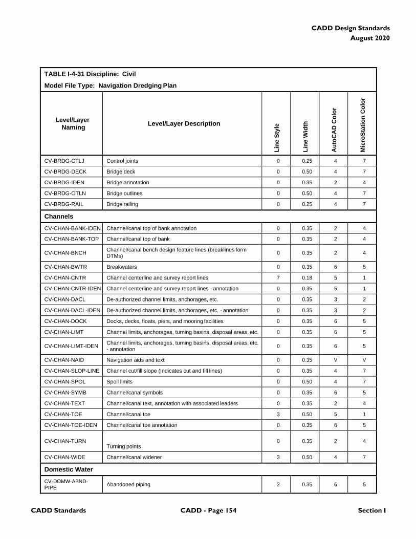
CADD Standards CADD - Page 154 Section I
CADD Design Standards
August 2020
TABLE I-4-31 Discipline: Civil
Model File Type: Navigation Dredging Plan
Level/Layer
Naming
Level/Layer Description
Lin
e S
tyle
Lin
e W
idth
Au
toC
AD
Co
lor
Mic
roS
tati
on
Co
lor
CV-BRDG-CTLJ Control joints 0 0.25 4 7
CV-BRDG-DECK Bridge deck 0 0.50 4 7
CV-BRDG-IDEN Bridge annotation 0 0.35 2 4
CV-BRDG-OTLN Bridge outlines 0 0.50 4 7
CV-BRDG-RAIL Bridge railing 0 0.25 4 7
Channels
CV-CHAN-BANK-IDEN Channel/canal top of bank annotation 0 0.35 2 4
CV-CHAN-BANK-TOP Channel/canal top of bank 0 0.35 2 4
CV-CHAN-BNCH Channel/canal bench design feature lines (breaklines form DTMs)
0
0.35
2
4
CV-CHAN-BWTR Breakwaters 0 0.35 6 5
CV-CHAN-CNTR Channel centerline and survey report lines 7 0.18 5 1
CV-CHAN-CNTR-IDEN Channel centerline and survey report lines - annotation 0 0.35 5 1
CV-CHAN-DACL De-authorized channel limits, anchorages, etc. 0 0.35 3 2
CV-CHAN-DACL-IDEN De-authorized channel limits, anchorages, etc. - annotation 0 0.35 3 2
CV-CHAN-DOCK Docks, decks, floats, piers, and mooring facilities 0 0.35 6 5
CV-CHAN-LIMT Channel limits, anchorages, turning basins, disposal areas, etc. 0 0.35 6 5
CV-CHAN-LIMT-IDEN Channel limits, anchorages, turning basins, disposal areas, etc. - annotation
0
0.35
6
5
CV-CHAN-NAID Navigation aids and text 0 0.35 V V
CV-CHAN-SLOP-LINE Channel cut/fill slope (Indicates cut and fill lines) 0 0.35 4 7
CV-CHAN-SPOL Spoil limits 0 0.50 4 7
CV-CHAN-SYMB Channel/canal symbols 0 0.35 6 5
CV-CHAN-TEXT Channel/canal text, annotation with associated leaders 0 0.35 2 4
CV-CHAN-TOE Channel/canal toe 3 0.50 5 1
CV-CHAN-TOE-IDEN Channel/canal toe annotation 0 0.35 6 5
CV-CHAN-TURN
Turning points
0
0.35
2
4
CV-CHAN-WIDE Channel/canal widener 3 0.50 4 7
Domestic Water
CV-DOMW-ABND- PIPE
Abandoned piping
2
0.35
6
5
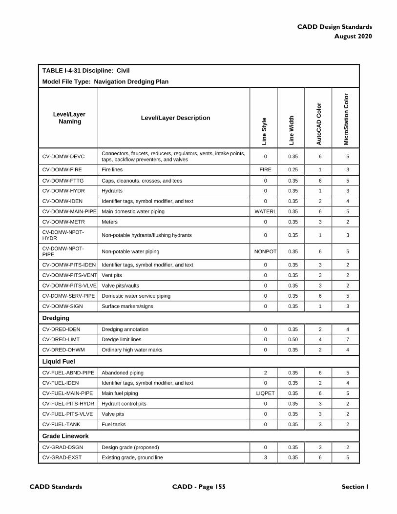
CADD Standards CADD - Page 155 Section I
CADD Design Standards
August 2020
TABLE I-4-31 Discipline: Civil
Model File Type: Navigation Dredging Plan
Level/Layer
Naming
Level/Layer Description
Lin
e S
tyle
Lin
e W
idth
Au
toC
AD
Co
lor
Mic
roS
tati
on
Co
lor
CV-DOMW-DEVC Connectors, faucets, reducers, regulators, vents, intake points, taps, backflow preventers, and valves
0
0.35
6
5
CV-DOMW-FIRE Fire lines FIRE 0.25 1 3
CV-DOMW-FTTG Caps, cleanouts, crosses, and tees 0 0.35 6 5
CV-DOMW-HYDR Hydrants 0 0.35 1 3
CV-DOMW-IDEN Identifier tags, symbol modifier, and text 0 0.35 2 4
CV-DOMW-MAIN-PIPE Main domestic water piping WATERL 0.35 6 5
CV-DOMW-METR Meters 0 0.35 3 2
CV-DOMW-NPOT- HYDR
Non-potable hydrants/flushing hydrants
0
0.35
1
3
CV-DOMW-NPOT- PIPE
Non-potable water piping
NONPOT
0.35
6
5
CV-DOMW-PITS-IDEN Identifier tags, symbol modifier, and text 0 0.35 3 2
CV-DOMW-PITS-VENT Vent pits 0 0.35 3 2
CV-DOMW-PITS-VLVE Valve pits/vaults 0 0.35 3 2
CV-DOMW-SERV-PIPE Domestic water service piping 0 0.35 6 5
CV-DOMW-SIGN Surface markers/signs 0 0.35 1 3
Dredging
CV-DRED-IDEN Dredging annotation 0 0.35 2 4
CV-DRED-LIMT Dredge limit lines 0 0.50 4 7
CV-DRED-OHWM Ordinary high water marks 0 0.35 2 4
Liquid Fuel
CV-FUEL-ABND-PIPE Abandoned piping 2 0.35 6 5
CV-FUEL-IDEN Identifier tags, symbol modifier, and text 0 0.35 2 4
CV-FUEL-MAIN-PIPE Main fuel piping LIQPET 0.35 6 5
CV-FUEL-PITS-HYDR Hydrant control pits 0 0.35 3 2
CV-FUEL-PITS-VLVE Valve pits 0 0.35 3 2
CV-FUEL-TANK Fuel tanks 0 0.35 3 2
Grade Linework
CV-GRAD-DSGN Design grade (proposed) 0 0.35 3 2
CV-GRAD-EXST Existing grade, ground line 3 0.35 6 5
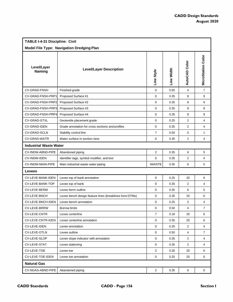
CADD Standards CADD - Page 156 Section I
CADD Design Standards
August 2020
TABLE I-4-31 Discipline: Civil
Model File Type: Navigation Dredging Plan
Level/Layer
Naming
Level/Layer Description
Lin
e S
tyle
Lin
e W
idth
Au
toC
AD
Co
lor
Mic
roS
tati
on
Co
lor
CV-GRAD-FNSH Finished grade 0 0.50 4 7
CV-GRAD-FNSH-PRP1 Proposed Surface #1 0 0.35 8 9
CV-GRAD-FNSH-PRP2 Proposed Surface #2 0 0.35 8 9
CV-GRAD-FNSH-PRP3 Proposed Surface #3 0 0.35 8 9
CV-GRAD-FNSH-PRP4 Proposed Surface #4 0 0.35 8 9
CV-GRAD-GTXL Geotextile placement grade 0 0.25 2 4
CV-GRAD-IDEN Grade annotation for cross sections and profiles 0 0.35 2 4
CV-GRAD-SCLN Stability control line 7 0.50 5 1
CV-GRAD-WATR Water surface in section view 0 0.35 2 4
Industrial Waste Water
CV-INDW-ABND-PIPE Abandoned piping 2 0.35 6 5
CV-INDW-IDEN Identifier tags, symbol modifier, and text 0 0.35 2 4
CV-INDW-MAIN-PIPE Main industrial waste water piping IWASTE 0.35 6 5
Levees
CV-LEVE-BANK-IDEN Levee top of bank annotation 0 0.25 20 6
CV-LEVE-BANK-TOP Levee top of bank 0 0.35 2 4
CV-LEVE-BERM Levee berm outline 0 0.35 6 5
CV-LEVE-BNCH Levee bench design feature lines (breaklines form DTMs) 0 0.35 20 6
CV-LEVE-BNCH-IDEN Levee bench annotation 0 0.25 2 4
CV-LEVE-BRRW Borrow limits 0 0.50 4 7
CV-LEVE-CNTR Levee centerline 7 0.18 20 6
CV-LEVE-CNTR-IDEN Levee centerline annotation 0 0.35 20 6
CV-LEVE-IDEN Levee annotation 0 0.35 2 4
CV-LEVE-OTLN Levee outline 0 0.50 4 7
CV-LEVE-SLOP Levee slope indicator with annotation 0 0.35 2 4
CV-LEVE-STAT Levee stationing 0 0.35 2 4
CV-LEVE-TOE Levee toe 2 0.35 20 6
CV-LEVE-TOE-IDEN Levee toe annotation 0 0.25 20 6
Natural Gas
CV-NGAS-ABND-PIPE Abandoned piping 2 0.35 6 5
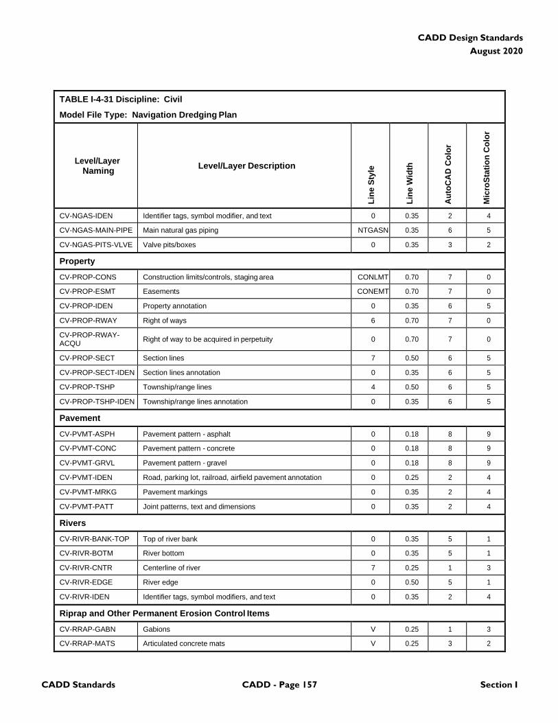
CADD Standards CADD - Page 157 Section I
CADD Design Standards
August 2020
TABLE I-4-31 Discipline: Civil
Model File Type: Navigation Dredging Plan
Level/Layer
Naming
Level/Layer Description
Lin
e S
tyle
Lin
e W
idth
Au
toC
AD
Co
lor
Mic
roS
tati
on
Co
lor
CV-NGAS-IDEN Identifier tags, symbol modifier, and text 0 0.35 2 4
CV-NGAS-MAIN-PIPE Main natural gas piping NTGASN 0.35 6 5
CV-NGAS-PITS-VLVE Valve pits/boxes 0 0.35 3 2
Property
CV-PROP-CONS Construction limits/controls, staging area CONLMT 0.70 7 0
CV-PROP-ESMT Easements CONEMT 0.70 7 0
CV-PROP-IDEN Property annotation 0 0.35 6 5
CV-PROP-RWAY Right of ways 6 0.70 7 0
CV-PROP-RWAY- ACQU
Right of way to be acquired in perpetuity
0
0.70
7
0
CV-PROP-SECT Section lines 7 0.50 6 5
CV-PROP-SECT-IDEN Section lines annotation 0 0.35 6 5
CV-PROP-TSHP Township/range lines 4 0.50 6 5
CV-PROP-TSHP-IDEN Township/range lines annotation 0 0.35 6 5
Pavement
CV-PVMT-ASPH Pavement pattern - asphalt 0 0.18 8 9
CV-PVMT-CONC Pavement pattern - concrete 0 0.18 8 9
CV-PVMT-GRVL Pavement pattern - gravel 0 0.18 8 9
CV-PVMT-IDEN Road, parking lot, railroad, airfield pavement annotation 0 0.25 2 4
CV-PVMT-MRKG Pavement markings 0 0.35 2 4
CV-PVMT-PATT Joint patterns, text and dimensions 0 0.35 2 4
Rivers
CV-RIVR-BANK-TOP Top of river bank 0 0.35 5 1
CV-RIVR-BOTM River bottom 0 0.35 5 1
CV-RIVR-CNTR Centerline of river 7 0.25 1 3
CV-RIVR-EDGE River edge 0 0.50 5 1
CV-RIVR-IDEN Identifier tags, symbol modifiers, and text 0 0.35 2 4
Riprap and Other Permanent Erosion Control Items
CV-RRAP-GABN Gabions V 0.25 1 3
CV-RRAP-MATS Articulated concrete mats V 0.25 3 2
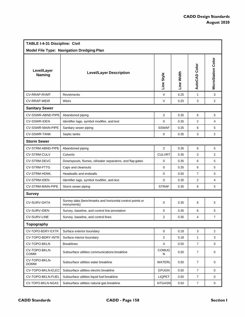
CADD Standards CADD - Page 158 Section I
CADD Design Standards
August 2020
TABLE I-4-31 Discipline: Civil
Model File Type: Navigation Dredging Plan
Level/Layer
Naming
Level/Layer Description
Lin
e S
tyle
Lin
e W
idth
Au
toC
AD
Co
lor
Mic
roS
tati
on
Co
lor
CV-RRAP-RVMT Revetments V 0.25 1 3
CV-RRAP-WEIR Weirs V 0.25 3 2
Sanitary Sewer
CV-SSWR-ABND-PIPE Abandoned piping 2 0.35 6 5
CV-SSWR-IDEN Identifier tags, symbol modifier, and text 0 0.35 2 4
CV-SSWR-MAIN-PIPE Sanitary sewer piping SSWAF 0.35 6 5
CV-SSWR-TANK Septic tanks 0 0.35 3 2
Storm Sewer
CV-STRM-ABND-PIPE Abandoned piping 2 0.35 6 5
CV-STRM-CULV Culverts CULVRT 0.35 3 2
CV-STRM-DEVC Downspouts, flumes, oil/water separators, and flap gates 0 0.35 6 5
CV-STRM-FTTG Caps and cleanouts 0 0.35 6 5
CV-STRM-HDWL Headwalls and endwalls 0 0.50 7 0
CV-STRM-IDEN Identifier tags, symbol modifier, and text 0 0.35 2 4
CV-STRM-MAIN-PIPE Storm sewer piping STRAF 0.35 6 5
Survey
CV-SURV-DATA Survey data (benchmarks and horizontal control points or monuments)
0
0.35
6
5
CV-SURV-IDEN Survey, baseline, and control line annotation 0 0.35 6 5
CV-SURV-LINE Survey, baseline, and control lines 2 0.35 4 7
Topography
CV-TOPO-BDRY-EXTR Surface exterior boundary 0 0.18 3 2
CV-TOPO-BDRY-INTR Surface interior boundary 2 0.18 1 3
CV-TOPO-BKLN Breaklines 4 0.50 7 0
CV-TOPO-BKLN- COMM
Subsurface utilities communications breakline COMUG
N
0.50
7
0
CV-TOPO-BKLN- DOMW
Subsurface utilities water breakline
WATERL
0.50
7
0
CV-TOPO-BKLN-ELEC Subsurface utilities electric breakline EPUGN 0.50 7 0
CV-TOPO-BKLN-FUEL Subsurface utilities liquid fuel breakline LIQPET 0.50 7 0
CV-TOPO-BKLN-NGAS Subsurface utilities natural gas breakline NTGASN 0.50 7 0
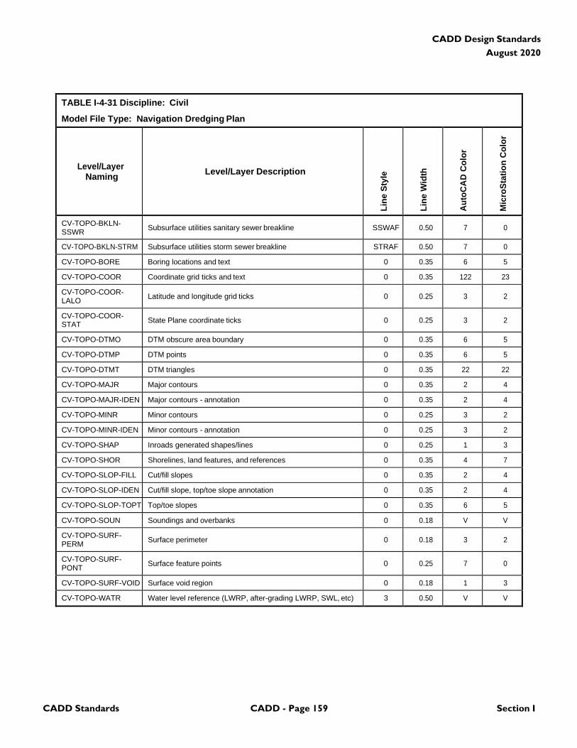
CADD Standards CADD - Page 159 Section I
CADD Design Standards
August 2020
TABLE I-4-31 Discipline: Civil
Model File Type: Navigation Dredging Plan
Level/Layer
Naming
Level/Layer Description
Lin
e S
tyle
Lin
e W
idth
Au
toC
AD
Co
lor
Mic
roS
tati
on
Co
lor
CV-TOPO-BKLN- SSWR
Subsurface utilities sanitary sewer breakline
SSWAF
0.50
7
0
CV-TOPO-BKLN-STRM Subsurface utilities storm sewer breakline STRAF 0.50 7 0
CV-TOPO-BORE Boring locations and text 0 0.35 6 5
CV-TOPO-COOR Coordinate grid ticks and text 0 0.35 122 23
CV-TOPO-COOR- LALO
Latitude and longitude grid ticks
0
0.25
3
2
CV-TOPO-COOR- STAT
State Plane coordinate ticks
0
0.25
3
2
CV-TOPO-DTMO DTM obscure area boundary 0 0.35 6 5
CV-TOPO-DTMP DTM points 0 0.35 6 5
CV-TOPO-DTMT DTM triangles 0 0.35 22 22
CV-TOPO-MAJR Major contours 0 0.35 2 4
CV-TOPO-MAJR-IDEN Major contours - annotation 0 0.35 2 4
CV-TOPO-MINR Minor contours 0 0.25 3 2
CV-TOPO-MINR-IDEN Minor contours - annotation 0 0.25 3 2
CV-TOPO-SHAP Inroads generated shapes/lines 0 0.25 1 3
CV-TOPO-SHOR Shorelines, land features, and references 0 0.35 4 7
CV-TOPO-SLOP-FILL Cut/fill slopes 0 0.35 2 4
CV-TOPO-SLOP-IDEN Cut/fill slope, top/toe slope annotation 0 0.35 2 4
CV-TOPO-SLOP-TOPT Top/toe slopes 0 0.35 6 5
CV-TOPO-SOUN Soundings and overbanks 0 0.18 V V
CV-TOPO-SURF- PERM
Surface perimeter
0
0.18
3
2
CV-TOPO-SURF- PONT
Surface feature points
0
0.25
7
0
CV-TOPO-SURF-VOID Surface void region 0 0.18 1 3
CV-TOPO-WATR Water level reference (LWRP, after-grading LWRP, SWL, etc) 3 0.50 V V
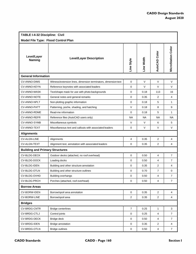
CADD Standards CADD - Page 160 Section I
CADD Design Standards
August 2020
TABLE I-4-32 Discipline: Civil
Model File Type: Flood Control Plan
Level/Layer
Naming
Level/Layer Description
Lin
e S
tyle
Lin
e W
idth
Au
toC
AD
Co
lor
Mic
roS
tati
on
Co
lor
General Information
CV-ANNO-DIMS Witness/extension lines, dimension terminators, dimension text 0 V V V
CV-ANNO-KEYN Reference keynotes with associated leaders 0 V V V
CV-ANNO-MASK Text/shape mask for use with photo backgrounds 0 0.18 113 16
CV-ANNO-NOTE General notes and general remarks 0 0.35 2 4
CV-ANNO-NPLT Non-plotting graphic information 0 0.18 5 1
CV-ANNO-PATT Patterning, poche, shading, and hatching V 0.18 8 9
CV-ANNO-RDME Read-me information 0 0.18 5 1
CV-ANNO-REFR Reference files (AutoCAD users only) NA NA NA NA
CV-ANNO-SYMB Miscellaneous symbols V V 6 5
CV-ANNO-TEXT Miscellaneous text and callouts with associated leaders 0 V V V
Alignments
CV-ALGN-LINE Alignments 4 0.35 2 4
CV-ALGN-TEXT Alignment text, annotation with associated leaders 0 0.35 2 4
Building and Primary Structures
CV-BLDG-DECK Outdoor decks (attached, no roof overhead) 0 0.50 4 7
CV-BLDG-DOCK Loading docks 0 0.50 4 7
CV-BLDG-IDEN Building and other structure annotation 0 0.35 2 4
CV-BLDG-OTLN Building and other structure outlines 0 0.70 7 0
CV-BLDG-OVHD Building overhangs 0 0.50 4 7
CV-BLDG-PRCH Porches (attached, roof overhead) 0 0.50 4 7
Borrow Areas
CV-BORW-IDEN Borrow/spoil area annotation 0 0.35 2 4
CV-BORW-LINE Borrow/spoil area 2 0.35 2 4
Bridges
CV-BRDG-CNTR Bridge centerlines 7 0.25 1 3
CV-BRDG-CTLJ Control joints 0 0.25 4 7
CV-BRDG-DECK Bridge deck 0 0.50 4 7
CV-BRDG-IDEN Bridge annotation 0 0.35 2 4
CV-BRDG-OTLN Bridge outlines 0 0.50 4 7
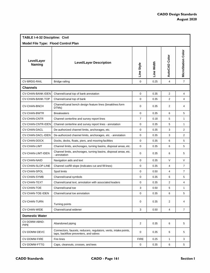
CADD Standards CADD - Page 161 Section I
CADD Design Standards
August 2020
TABLE I-4-32 Discipline: Civil
Model File Type: Flood Control Plan
Level/Layer
Naming
Level/Layer Description
Lin
e S
tyle
Lin
e W
idth
Au
toC
AD
Co
lor
Mic
roS
tati
on
Co
lor
CV-BRDG-RAIL Bridge railing 0 0.25 4 7
Channels
CV-CHAN-BANK-IDEN Channel/canal top of bank annotation 0 0.35 2 4
CV-CHAN-BANK-TOP Channel/canal top of bank 0 0.35 2 4
CV-CHAN-BNCH Channel/canal bench design feature lines (breaklines form DTMs)
0
0.35
2
4
CV-CHAN-BWTR Breakwaters 0 0.35 6 5
CV-CHAN-CNTR Channel centerline and survey report lines 7 0.18 5 1
CV-CHAN-CNTR-IDEN Channel centerline and survey report lines - annotation 0 0.35 5 1
CV-CHAN-DACL De-authorized channel limits, anchorages, etc. 0 0.35 3 2
CV-CHAN-DACL-IDEN De-authorized channel limits, anchorages, etc. - annotation 0 0.35 3 2
CV-CHAN-DOCK Docks, decks, floats, piers, and mooring facilities 0 0.35 6 5
CV-CHAN-LIMT Channel limits, anchorages, turning basins, disposal areas, etc. 0 0.35 6 5
CV-CHAN-LIMT-IDEN Channel limits, anchorages, turning basins, disposal areas, etc. - annotation
0
0.35
6
5
CV-CHAN-NAID Navigation aids and text 0 0.35 V V
CV-CHAN-SLOP-LINE Channel cut/fill slope (Indicates cut and fill lines) 0 0.35 4 7
CV-CHAN-SPOL Spoil limits 0 0.50 4 7
CV-CHAN-SYMB Channel/canal symbols 0 0.35 6 5
CV-CHAN-TEXT Channel/canal text, annotation with associated leaders 0 0.35 2 4
CV-CHAN-TOE Channel/canal toe 3 0.50 5 1
CV-CHAN-TOE-IDEN Channel/canal toe annotation 0 0.35 6 5
CV-CHAN-TURN
Turning points
0
0.35
2
4
CV-CHAN-WIDE Channel/canal widener 3 0.50 4 7
Domestic Water
CV-DOMW-ABND- PIPE
Abandoned piping
2
0.35
6
5
CV-DOMW-DEVC Connectors, faucets, reducers, regulators, vents, intake points, taps, backflow preventers, and valves
0
0.35
6
5
CV-DOMW-FIRE Fire lines FIRE 0.25 1 3
CV-DOMW-FTTG Caps, cleanouts, crosses, and tees 0 0.35 6 5
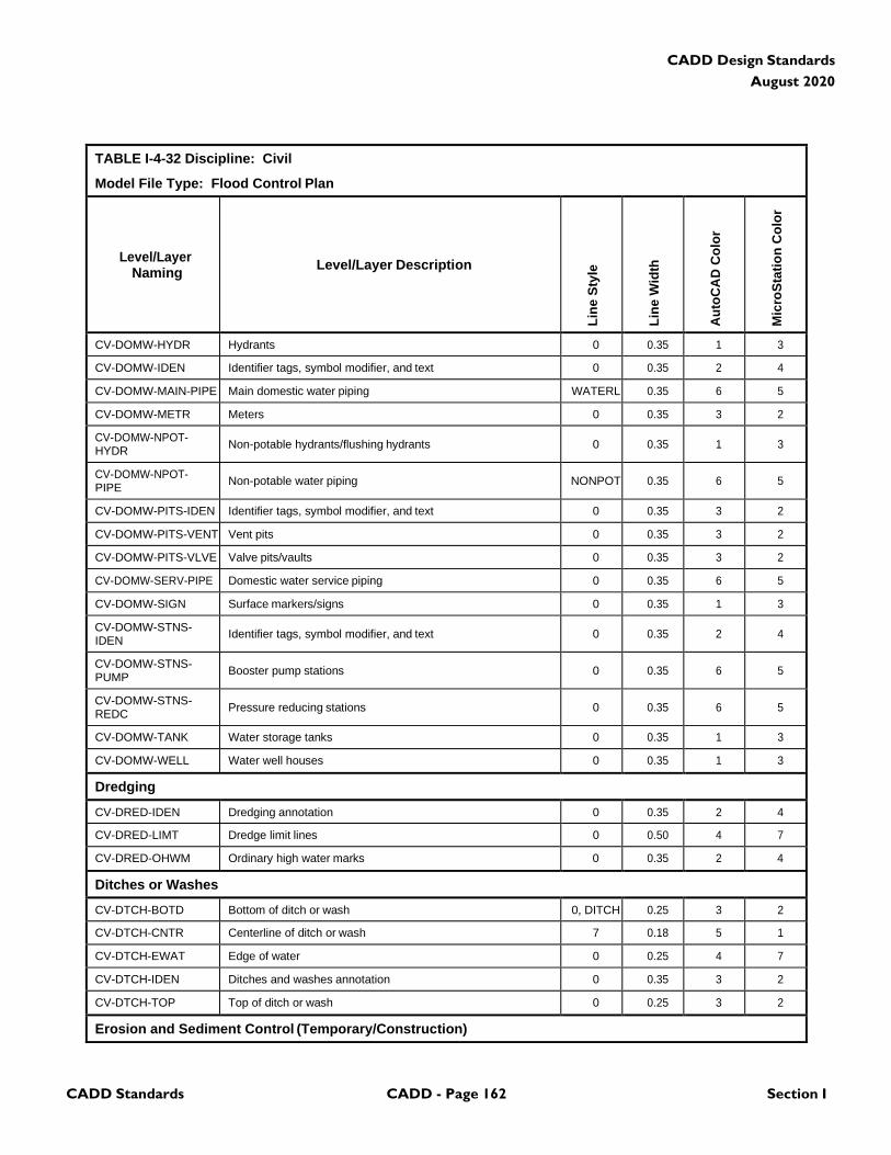
CADD Standards CADD - Page 162 Section I
CADD Design Standards
August 2020
TABLE I-4-32 Discipline: Civil
Model File Type: Flood Control Plan
Level/Layer
Naming
Level/Layer Description
Lin
e S
tyle
Lin
e W
idth
Au
toC
AD
Co
lor
Mic
roS
tati
on
Co
lor
CV-DOMW-HYDR Hydrants 0 0.35 1 3
CV-DOMW-IDEN Identifier tags, symbol modifier, and text 0 0.35 2 4
CV-DOMW-MAIN-PIPE Main domestic water piping WATERL 0.35 6 5
CV-DOMW-METR Meters 0 0.35 3 2
CV-DOMW-NPOT- HYDR
Non-potable hydrants/flushing hydrants
0
0.35
1
3
CV-DOMW-NPOT- PIPE
Non-potable water piping
NONPOT
0.35
6
5
CV-DOMW-PITS-IDEN Identifier tags, symbol modifier, and text 0 0.35 3 2
CV-DOMW-PITS-VENT Vent pits 0 0.35 3 2
CV-DOMW-PITS-VLVE Valve pits/vaults 0 0.35 3 2
CV-DOMW-SERV-PIPE Domestic water service piping 0 0.35 6 5
CV-DOMW-SIGN Surface markers/signs 0 0.35 1 3
CV-DOMW-STNS- IDEN
Identifier tags, symbol modifier, and text
0
0.35
2
4
CV-DOMW-STNS- PUMP
Booster pump stations
0
0.35
6
5
CV-DOMW-STNS- REDC
Pressure reducing stations
0
0.35
6
5
CV-DOMW-TANK Water storage tanks 0 0.35 1 3
CV-DOMW-WELL Water well houses 0 0.35 1 3
Dredging
CV-DRED-IDEN Dredging annotation 0 0.35 2 4
CV-DRED-LIMT Dredge limit lines 0 0.50 4 7
CV-DRED-OHWM Ordinary high water marks 0 0.35 2 4
Ditches or Washes
CV-DTCH-BOTD Bottom of ditch or wash 0, DITCH 0.25 3 2
CV-DTCH-CNTR Centerline of ditch or wash 7 0.18 5 1
CV-DTCH-EWAT Edge of water 0 0.25 4 7
CV-DTCH-IDEN Ditches and washes annotation 0 0.35 3 2
CV-DTCH-TOP Top of ditch or wash 0 0.25 3 2
Erosion and Sediment Control (Temporary/Construction)
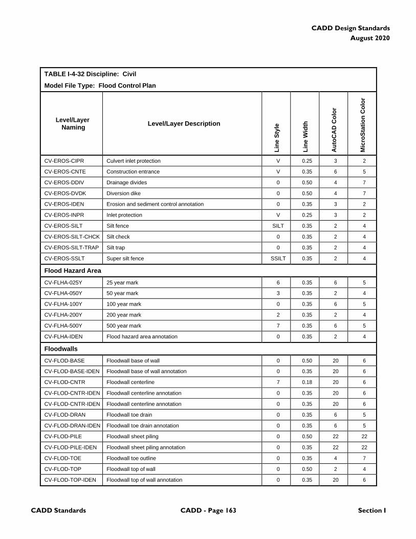
CADD Standards CADD - Page 163 Section I
CADD Design Standards
August 2020
TABLE I-4-32 Discipline: Civil
Model File Type: Flood Control Plan
Level/Layer
Naming
Level/Layer Description
Lin
e S
tyle
Lin
e W
idth
Au
toC
AD
Co
lor
Mic
roS
tati
on
Co
lor
CV-EROS-CIPR Culvert inlet protection V 0.25 3 2
CV-EROS-CNTE Construction entrance V 0.35 6 5
CV-EROS-DDIV Drainage divides 0 0.50 4 7
CV-EROS-DVDK Diversion dike 0 0.50 4 7
CV-EROS-IDEN Erosion and sediment control annotation 0 0.35 3 2
CV-EROS-INPR Inlet protection V 0.25 3 2
CV-EROS-SILT Silt fence SILT 0.35 2 4
CV-EROS-SILT-CHCK Silt check 0 0.35 2 4
CV-EROS-SILT-TRAP Silt trap 0 0.35 2 4
CV-EROS-SSLT Super silt fence SSILT 0.35 2 4
Flood Hazard Area
CV-FLHA-025Y 25 year mark 6 0.35 6 5
CV-FLHA-050Y 50 year mark 3 0.35 2 4
CV-FLHA-100Y 100 year mark 0 0.35 6 5
CV-FLHA-200Y 200 year mark 2 0.35 2 4
CV-FLHA-500Y 500 year mark 7 0.35 6 5
CV-FLHA-IDEN Flood hazard area annotation 0 0.35 2 4
Floodwalls
CV-FLOD-BASE Floodwall base of wall 0 0.50 20 6
CV-FLOD-BASE-IDEN Floodwall base of wall annotation 0 0.35 20 6
CV-FLOD-CNTR Floodwall centerline 7 0.18 20 6
CV-FLOD-CNTR-IDEN Floodwall centerline annotation 0 0.35 20 6
CV-FLOD-CNTR-IDEN Floodwall centerline annotation 0 0.35 20 6
CV-FLOD-DRAN Floodwall toe drain 0 0.35 6 5
CV-FLOD-DRAN-IDEN Floodwall toe drain annotation 0 0.35 6 5
CV-FLOD-PILE Floodwall sheet piling 0 0.50 22 22
CV-FLOD-PILE-IDEN Floodwall sheet piling annotation 0 0.35 22 22
CV-FLOD-TOE Floodwall toe outline 0 0.35 4 7
CV-FLOD-TOP Floodwall top of wall 0 0.50 2 4
CV-FLOD-TOP-IDEN Floodwall top of wall annotation 0 0.35 20 6
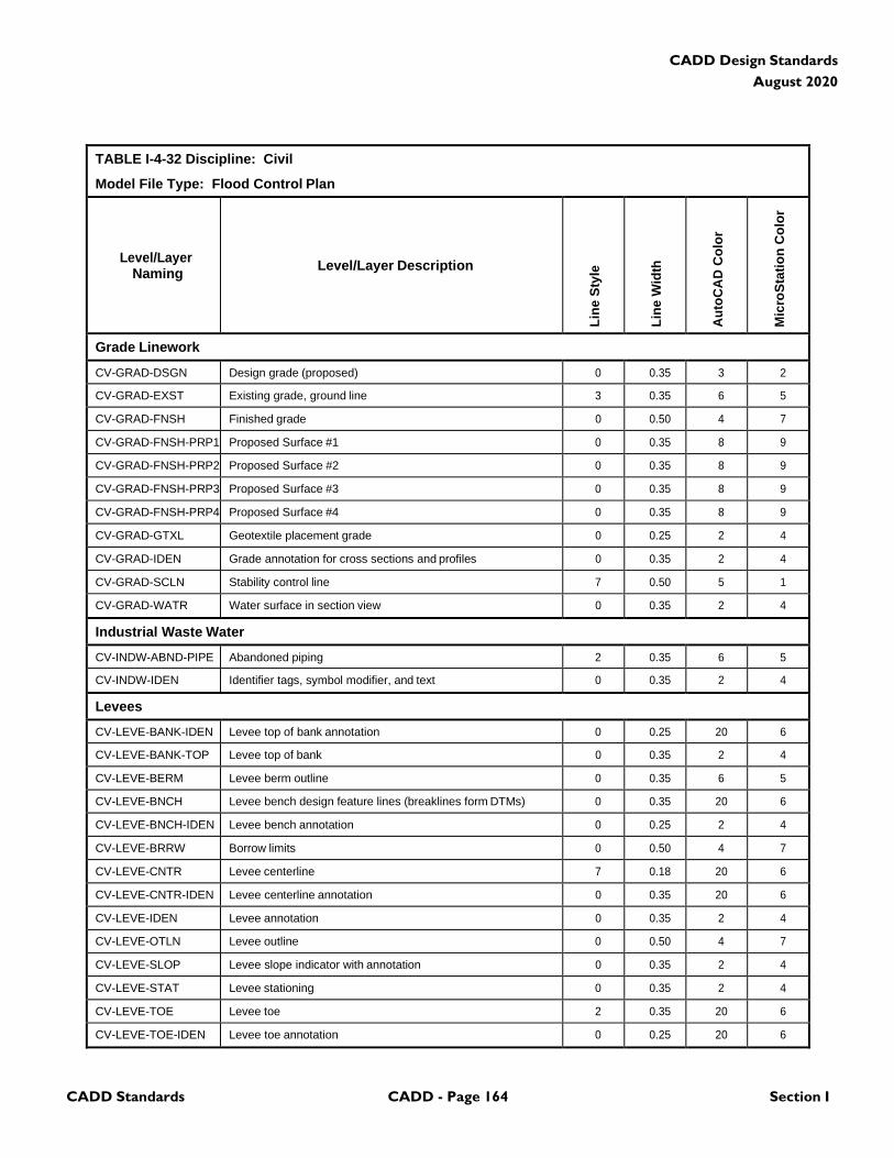
CADD Standards CADD - Page 164 Section I
CADD Design Standards
August 2020
TABLE I-4-32 Discipline: Civil
Model File Type: Flood Control Plan
Level/Layer
Naming
Level/Layer Description
Lin
e S
tyle
Lin
e W
idth
Au
toC
AD
Co
lor
Mic
roS
tati
on
Co
lor
Grade Linework
CV-GRAD-DSGN Design grade (proposed) 0 0.35 3 2
CV-GRAD-EXST Existing grade, ground line 3 0.35 6 5
CV-GRAD-FNSH Finished grade 0 0.50 4 7
CV-GRAD-FNSH-PRP1 Proposed Surface #1 0 0.35 8 9
CV-GRAD-FNSH-PRP2 Proposed Surface #2 0 0.35 8 9
CV-GRAD-FNSH-PRP3 Proposed Surface #3 0 0.35 8 9
CV-GRAD-FNSH-PRP4 Proposed Surface #4 0 0.35 8 9
CV-GRAD-GTXL Geotextile placement grade 0 0.25 2 4
CV-GRAD-IDEN Grade annotation for cross sections and profiles 0 0.35 2 4
CV-GRAD-SCLN Stability control line 7 0.50 5 1
CV-GRAD-WATR Water surface in section view 0 0.35 2 4
Industrial Waste Water
CV-INDW-ABND-PIPE Abandoned piping 2 0.35 6 5
CV-INDW-IDEN Identifier tags, symbol modifier, and text 0 0.35 2 4
Levees
CV-LEVE-BANK-IDEN Levee top of bank annotation 0 0.25 20 6
CV-LEVE-BANK-TOP Levee top of bank 0 0.35 2 4
CV-LEVE-BERM Levee berm outline 0 0.35 6 5
CV-LEVE-BNCH Levee bench design feature lines (breaklines form DTMs) 0 0.35 20 6
CV-LEVE-BNCH-IDEN Levee bench annotation 0 0.25 2 4
CV-LEVE-BRRW Borrow limits 0 0.50 4 7
CV-LEVE-CNTR Levee centerline 7 0.18 20 6
CV-LEVE-CNTR-IDEN Levee centerline annotation 0 0.35 20 6
CV-LEVE-IDEN Levee annotation 0 0.35 2 4
CV-LEVE-OTLN Levee outline 0 0.50 4 7
CV-LEVE-SLOP Levee slope indicator with annotation 0 0.35 2 4
CV-LEVE-STAT Levee stationing 0 0.35 2 4
CV-LEVE-TOE Levee toe 2 0.35 20 6
CV-LEVE-TOE-IDEN Levee toe annotation 0 0.25 20 6
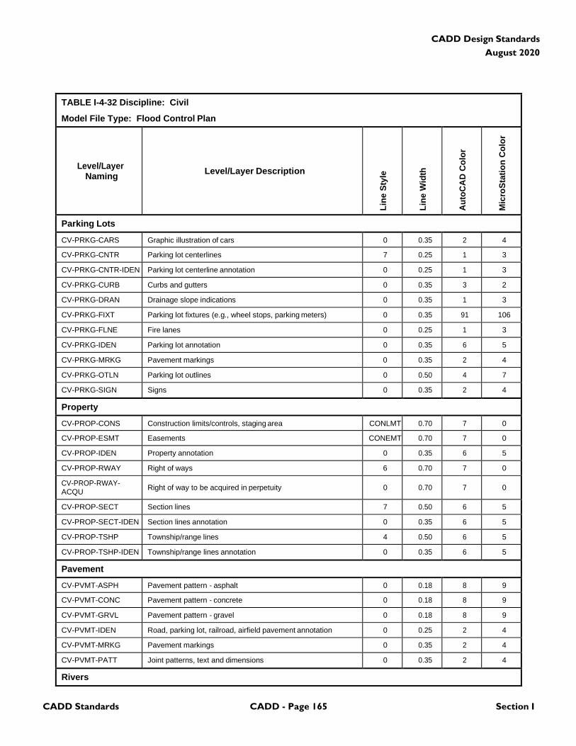
CADD Standards CADD - Page 165 Section I
CADD Design Standards
August 2020
TABLE I-4-32 Discipline: Civil
Model File Type: Flood Control Plan
Level/Layer
Naming
Level/Layer Description
Lin
e S
tyle
Lin
e W
idth
Au
toC
AD
Co
lor
Mic
roS
tati
on
Co
lor
Parking Lots
CV-PRKG-CARS Graphic illustration of cars 0 0.35 2 4
CV-PRKG-CNTR Parking lot centerlines 7 0.25 1 3
CV-PRKG-CNTR-IDEN Parking lot centerline annotation 0 0.25 1 3
CV-PRKG-CURB Curbs and gutters 0 0.35 3 2
CV-PRKG-DRAN Drainage slope indications 0 0.35 1 3
CV-PRKG-FIXT Parking lot fixtures (e.g., wheel stops, parking meters) 0 0.35 91 106
CV-PRKG-FLNE Fire lanes 0 0.25 1 3
CV-PRKG-IDEN Parking lot annotation 0 0.35 6 5
CV-PRKG-MRKG Pavement markings 0 0.35 2 4
CV-PRKG-OTLN Parking lot outlines 0 0.50 4 7
CV-PRKG-SIGN Signs 0 0.35 2 4
Property
CV-PROP-CONS Construction limits/controls, staging area CONLMT 0.70 7 0
CV-PROP-ESMT Easements CONEMT 0.70 7 0
CV-PROP-IDEN Property annotation 0 0.35 6 5
CV-PROP-RWAY Right of ways 6 0.70 7 0
CV-PROP-RWAY- ACQU
Right of way to be acquired in perpetuity
0
0.70
7
0
CV-PROP-SECT Section lines 7 0.50 6 5
CV-PROP-SECT-IDEN Section lines annotation 0 0.35 6 5
CV-PROP-TSHP Township/range lines 4 0.50 6 5
CV-PROP-TSHP-IDEN Township/range lines annotation 0 0.35 6 5
Pavement
CV-PVMT-ASPH Pavement pattern - asphalt 0 0.18 8 9
CV-PVMT-CONC Pavement pattern - concrete 0 0.18 8 9
CV-PVMT-GRVL Pavement pattern - gravel 0 0.18 8 9
CV-PVMT-IDEN Road, parking lot, railroad, airfield pavement annotation 0 0.25 2 4
CV-PVMT-MRKG Pavement markings 0 0.35 2 4
CV-PVMT-PATT Joint patterns, text and dimensions 0 0.35 2 4
Rivers
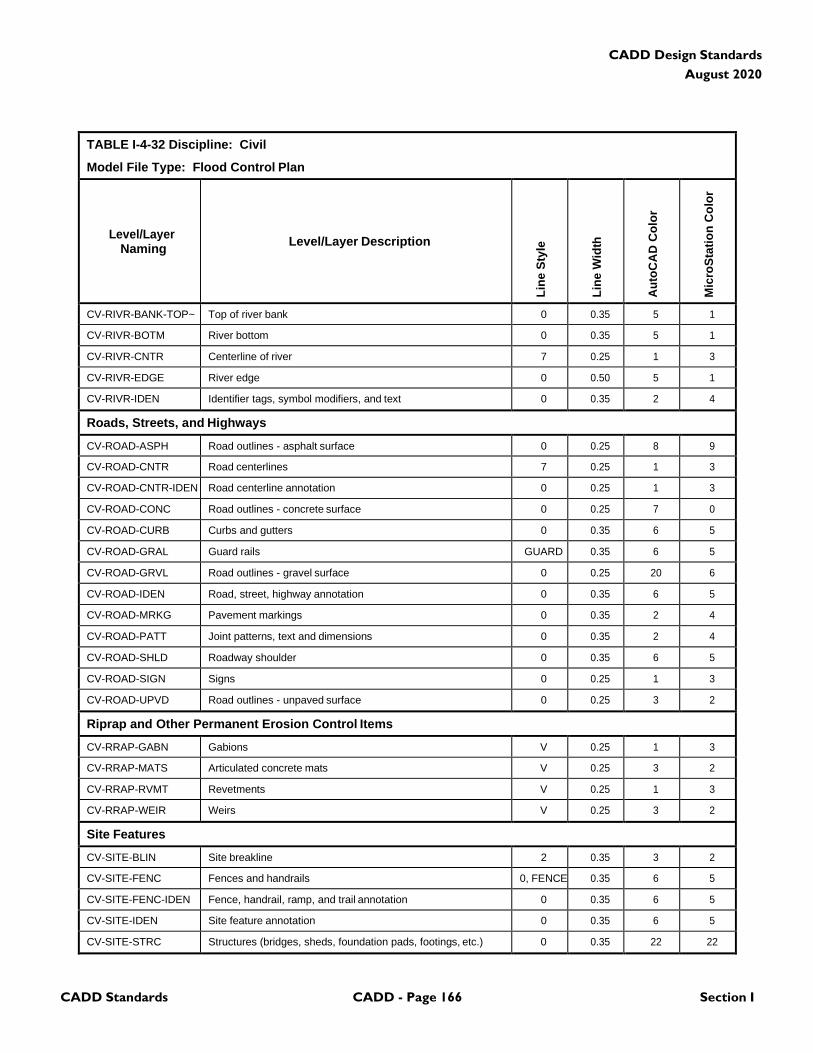
CADD Standards CADD - Page 166 Section I
CADD Design Standards
August 2020
TABLE I-4-32 Discipline: Civil
Model File Type: Flood Control Plan
Level/Layer
Naming
Level/Layer Description
Lin
e S
tyle
Lin
e W
idth
Au
toC
AD
Co
lor
Mic
roS
tati
on
Co
lor
CV-RIVR-BANK-TOP~ Top of river bank 0 0.35 5 1
CV-RIVR-BOTM River bottom 0 0.35 5 1
CV-RIVR-CNTR Centerline of river 7 0.25 1 3
CV-RIVR-EDGE River edge 0 0.50 5 1
CV-RIVR-IDEN Identifier tags, symbol modifiers, and text 0 0.35 2 4
Roads, Streets, and Highways
CV-ROAD-ASPH Road outlines - asphalt surface 0 0.25 8 9
CV-ROAD-CNTR Road centerlines 7 0.25 1 3
CV-ROAD-CNTR-IDEN Road centerline annotation 0 0.25 1 3
CV-ROAD-CONC Road outlines - concrete surface 0 0.25 7 0
CV-ROAD-CURB Curbs and gutters 0 0.35 6 5
CV-ROAD-GRAL Guard rails GUARD 0.35 6 5
CV-ROAD-GRVL Road outlines - gravel surface 0 0.25 20 6
CV-ROAD-IDEN Road, street, highway annotation 0 0.35 6 5
CV-ROAD-MRKG Pavement markings 0 0.35 2 4
CV-ROAD-PATT Joint patterns, text and dimensions 0 0.35 2 4
CV-ROAD-SHLD Roadway shoulder 0 0.35 6 5
CV-ROAD-SIGN Signs 0 0.25 1 3
CV-ROAD-UPVD Road outlines - unpaved surface 0 0.25 3 2
Riprap and Other Permanent Erosion Control Items
CV-RRAP-GABN Gabions V 0.25 1 3
CV-RRAP-MATS Articulated concrete mats V 0.25 3 2
CV-RRAP-RVMT Revetments V 0.25 1 3
CV-RRAP-WEIR Weirs V 0.25 3 2
Site Features
CV-SITE-BLIN Site breakline 2 0.35 3 2
CV-SITE-FENC Fences and handrails 0, FENCE 0.35 6 5
CV-SITE-FENC-IDEN Fence, handrail, ramp, and trail annotation 0 0.35 6 5
CV-SITE-IDEN Site feature annotation 0 0.35 6 5
CV-SITE-STRC Structures (bridges, sheds, foundation pads, footings, etc.) 0 0.35 22 22
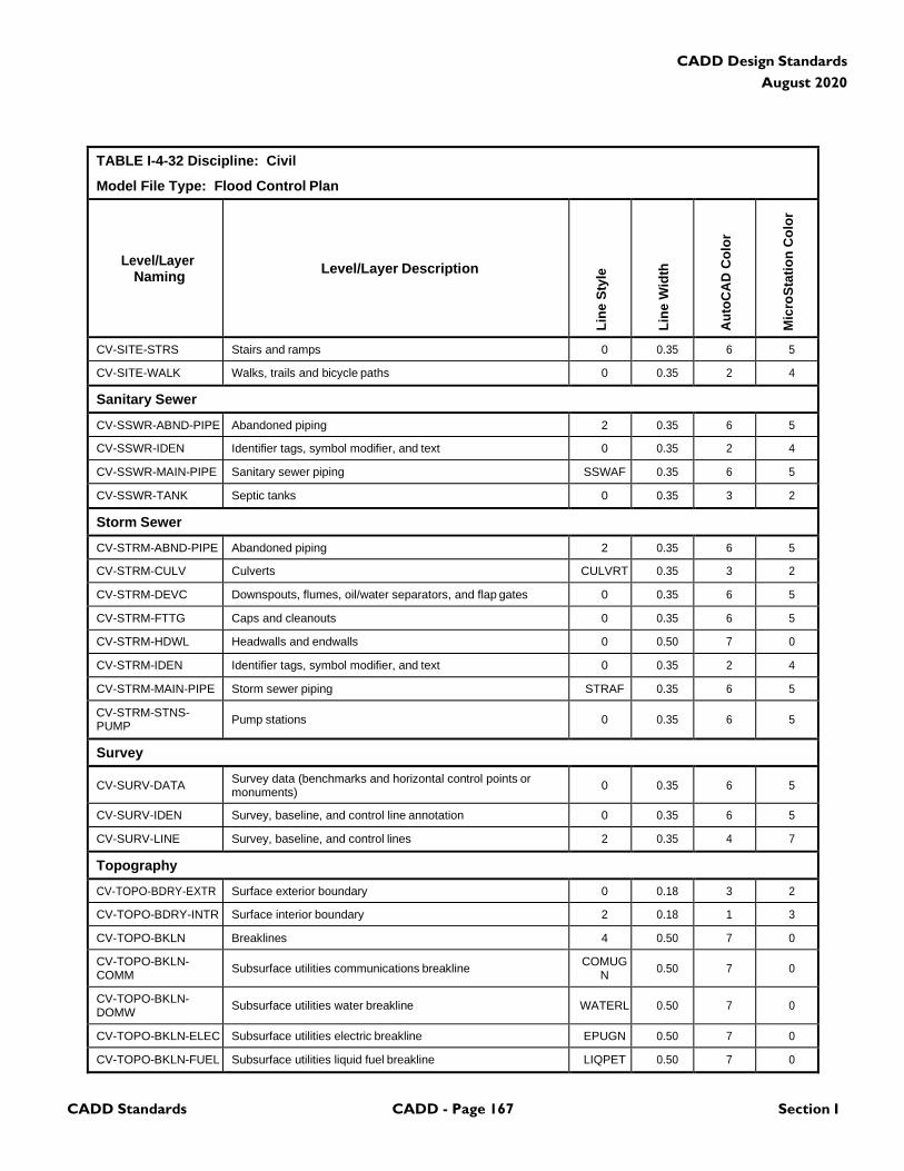
CADD Standards CADD - Page 167 Section I
CADD Design Standards
August 2020
TABLE I-4-32 Discipline: Civil
Model File Type: Flood Control Plan
Level/Layer
Naming
Level/Layer Description
Lin
e S
tyle
Lin
e W
idth
Au
toC
AD
Co
lor
Mic
roS
tati
on
Co
lor
CV-SITE-STRS Stairs and ramps 0 0.35 6 5
CV-SITE-WALK Walks, trails and bicycle paths 0 0.35 2 4
Sanitary Sewer
CV-SSWR-ABND-PIPE Abandoned piping 2 0.35 6 5
CV-SSWR-IDEN Identifier tags, symbol modifier, and text 0 0.35 2 4
CV-SSWR-MAIN-PIPE Sanitary sewer piping SSWAF 0.35 6 5
CV-SSWR-TANK Septic tanks 0 0.35 3 2
Storm Sewer
CV-STRM-ABND-PIPE Abandoned piping 2 0.35 6 5
CV-STRM-CULV Culverts CULVRT 0.35 3 2
CV-STRM-DEVC Downspouts, flumes, oil/water separators, and flap gates 0 0.35 6 5
CV-STRM-FTTG Caps and cleanouts 0 0.35 6 5
CV-STRM-HDWL Headwalls and endwalls 0 0.50 7 0
CV-STRM-IDEN Identifier tags, symbol modifier, and text 0 0.35 2 4
CV-STRM-MAIN-PIPE Storm sewer piping STRAF 0.35 6 5
CV-STRM-STNS- PUMP
Pump stations
0
0.35
6
5
Survey
CV-SURV-DATA Survey data (benchmarks and horizontal control points or monuments)
0
0.35
6
5
CV-SURV-IDEN Survey, baseline, and control line annotation 0 0.35 6 5
CV-SURV-LINE Survey, baseline, and control lines 2 0.35 4 7
Topography
CV-TOPO-BDRY-EXTR Surface exterior boundary 0 0.18 3 2
CV-TOPO-BDRY-INTR Surface interior boundary 2 0.18 1 3
CV-TOPO-BKLN Breaklines 4 0.50 7 0
CV-TOPO-BKLN- COMM
Subsurface utilities communications breakline COMUG
N
0.50
7
0
CV-TOPO-BKLN- DOMW
Subsurface utilities water breakline
WATERL
0.50
7
0
CV-TOPO-BKLN-ELEC Subsurface utilities electric breakline EPUGN 0.50 7 0
CV-TOPO-BKLN-FUEL Subsurface utilities liquid fuel breakline LIQPET 0.50 7 0
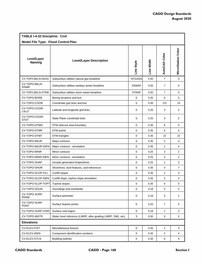
CADD Standards CADD - Page 168 Section I
CADD Design Standards
August 2020
TABLE I-4-32 Discipline: Civil
Model File Type: Flood Control Plan
Level/Layer
Naming
Level/Layer Description
Lin
e S
tyle
Lin
e W
idth
Au
toC
AD
Co
lor
Mic
roS
tati
on
Co
lor
CV-TOPO-BKLN-NGAS Subsurface utilities natural gas breakline NTGASN 0.50 7 0
CV-TOPO-BKLN- SSWR
Subsurface utilities sanitary sewer breakline
SSWAF
0.50
7
0
CV-TOPO-BKLN-STRM Subsurface utilities storm sewer breakline STRAF 0.50 7 0
CV-TOPO-BORE Boring locations and text 0 0.35 6 5
CV-TOPO-COOR Coordinate grid ticks and text 0 0.35 122 23
CV-TOPO-COOR- LALO
Latitude and longitude grid ticks
0
0.25
3
2
CV-TOPO-COOR- STAT
State Plane coordinate ticks
0
0.25
3
2
CV-TOPO-DTMO DTM obscure area boundary 0 0.35 6 5
CV-TOPO-DTMP DTM points 0 0.35 6 5
CV-TOPO-DTMT DTM triangles 0 0.35 22 22
CV-TOPO-MAJR Major contours 0 0.35 2 4
CV-TOPO-MAJR-IDEN Major contours - annotation 0 0.35 2 4
CV-TOPO-MINR Minor contours 0 0.25 3 2
CV-TOPO-MINR-IDEN Minor contours - annotation 0 0.25 3 2
CV-TOPO-SHAP Inroads generated shapes/lines 0 0.25 1 3
CV-TOPO-SHOR Shorelines, land features, and references 0 0.35 4 7
CV-TOPO-SLOP-FILL Cut/fill slopes 0 0.35 2 4
CV-TOPO-SLOP-IDEN Cut/fill slope, top/toe slope annotation 0 0.35 2 4
CV-TOPO-SLOP-TOPT Top/toe slopes 0 0.35 6 5
CV-TOPO-SOUN Soundings and overbanks 0 0.18 V V
CV-TOPO-SURF- PERM
Surface perimeter
0
0.18
3
2
CV-TOPO-SURF- PONT
Surface feature points
0
0.25
7
0
CV-TOPO-SURF-VOID Surface void region 0 0.18 1 3
CV-TOPO-WATR Water level reference (LWRP, after-grading LWRP, SWL, etc) 3 0.50 V V
Elevations
CV-ELEV-FIXT Miscellaneous fixtures 0 0.35 2 4
CV-ELEV-IDEN Component identification numbers 0 0.35 2 4
CV-ELEV-OTLN Building outlines 0 0.35 6 5
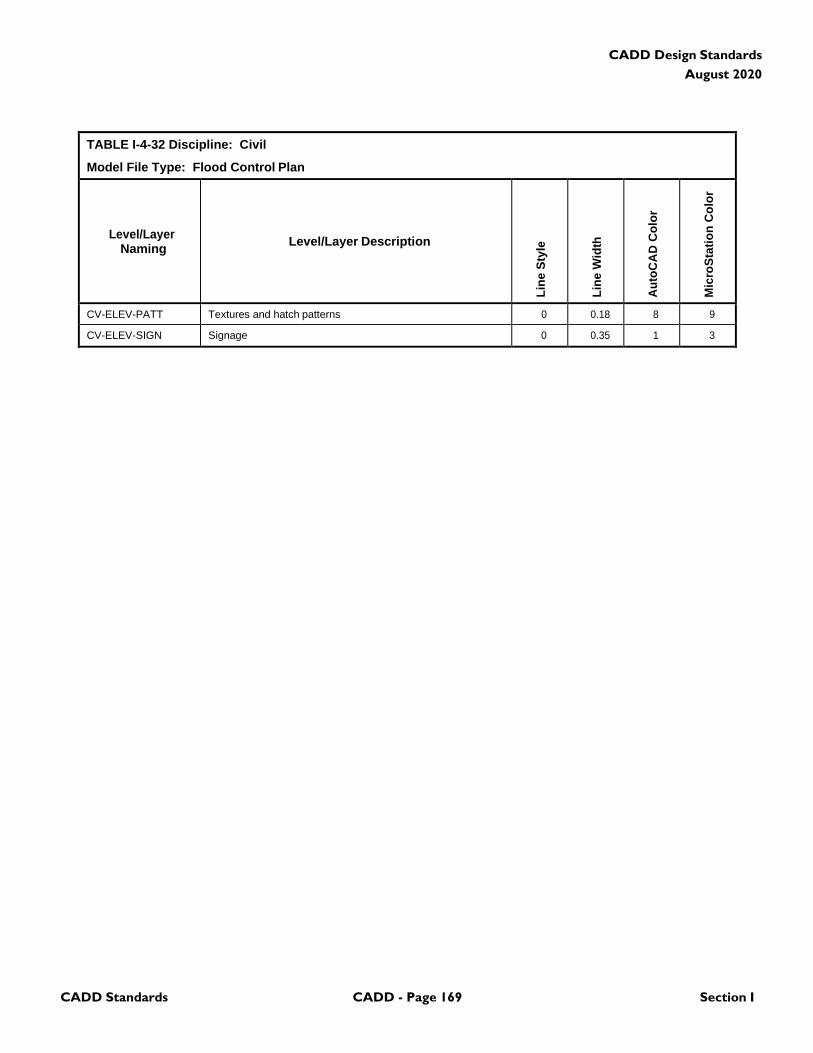
CADD Standards CADD - Page 169 Section I
CADD Design Standards
August 2020
TABLE I-4-32 Discipline: Civil
Model File Type: Flood Control Plan
Level/Layer
Naming
Level/Layer Description
Lin
e S
tyle
Lin
e W
idth
Au
toC
AD
Co
lor
Mic
roS
tati
on
Co
lor
CV-ELEV-PATT Textures and hatch patterns 0 0.18 8 9
CV-ELEV-SIGN Signage 0 0.35 1 3
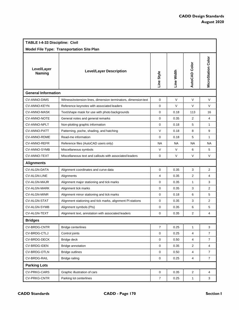
CADD Standards CADD - Page 170 Section I
CADD Design Standards
August 2020
TABLE I-4-33 Discipline: Civil
Model File Type: Transportation Site Plan
Level/Layer
Naming
Level/Layer Description
Lin
e S
tyle
Lin
e W
idth
Au
toC
AD
Co
lor
Mic
roS
tati
on
Co
lor
General Information
CV-ANNO-DIMS Witness/extension lines, dimension terminators, dimension text 0 V V V
CV-ANNO-KEYN Reference keynotes with associated leaders 0 V V V
CV-ANNO-MASK Text/shape mask for use with photo backgrounds 0 0.18 113 16
CV-ANNO-NOTE General notes and general remarks 0 0.35 2 4
CV-ANNO-NPLT Non-plotting graphic information 0 0.18 5 1
CV-ANNO-PATT Patterning, poche, shading, and hatching V 0.18 8 9
CV-ANNO-RDME Read-me information 0 0.18 5 1
CV-ANNO-REFR Reference files (AutoCAD users only) NA NA NA NA
CV-ANNO-SYMB Miscellaneous symbols V V 6 5
CV-ANNO-TEXT Miscellaneous text and callouts with associated leaders 0 V V V
Alignments
CV-ALGN-DATA Alignment coordinates and curve data 0 0.35 3 2
CV-ALGN-LINE Alignments 4 0.35 2 4
CV-ALGN-MAJR Alignment major stationing and tick marks 0 0.35 1 3
CV-ALGN-MARK Alignment tick marks 0 0.35 3 2
CV-ALGN-MINR Alignment minor stationing and tick marks 0 0.18 6 5
CV-ALGN-STAT Alignment stationing and tick marks, alignment PI stations 0 0.35 3 2
CV-ALGN-SYMB Alignment symbols (PIs) 0 0.35 6 5
CV-ALGN-TEXT Alignment text, annotation with associated leaders 0 0.35 2 4
Bridges
CV-BRDG-CNTR Bridge centerlines 7 0.25 1 3
CV-BRDG-CTLJ Control joints 0 0.25 4 7
CV-BRDG-DECK Bridge deck 0 0.50 4 7
CV-BRDG-IDEN Bridge annotation 0 0.35 2 4
CV-BRDG-OTLN Bridge outlines 0 0.50 4 7
CV-BRDG-RAIL Bridge railing 0 0.25 4 7
Parking Lots
CV-PRKG-CARS Graphic illustration of cars 0 0.35 2 4
CV-PRKG-CNTR Parking lot centerlines 7 0.25 1 3
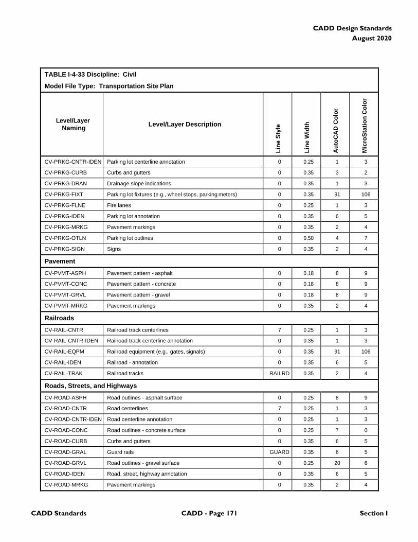
CADD Standards CADD - Page 171 Section I
CADD Design Standards
August 2020
TABLE I-4-33 Discipline: Civil
Model File Type: Transportation Site Plan
Level/Layer
Naming
Level/Layer Description
Lin
e S
tyle
Lin
e W
idth
Au
toC
AD
Co
lor
Mic
roS
tati
on
Co
lor
CV-PRKG-CNTR-IDEN Parking lot centerline annotation 0 0.25 1 3
CV-PRKG-CURB Curbs and gutters 0 0.35 3 2
CV-PRKG-DRAN Drainage slope indications 0 0.35 1 3
CV-PRKG-FIXT Parking lot fixtures (e.g., wheel stops, parking meters) 0 0.35 91 106
CV-PRKG-FLNE Fire lanes 0 0.25 1 3
CV-PRKG-IDEN Parking lot annotation 0 0.35 6 5
CV-PRKG-MRKG Pavement markings 0 0.35 2 4
CV-PRKG-OTLN Parking lot outlines 0 0.50 4 7
CV-PRKG-SIGN Signs 0 0.35 2 4
Pavement
CV-PVMT-ASPH Pavement pattern - asphalt 0 0.18 8 9
CV-PVMT-CONC Pavement pattern - concrete 0 0.18 8 9
CV-PVMT-GRVL Pavement pattern - gravel 0 0.18 8 9
CV-PVMT-MRKG Pavement markings 0 0.35 2 4
Railroads
CV-RAIL-CNTR Railroad track centerlines 7 0.25 1 3
CV-RAIL-CNTR-IDEN Railroad track centerline annotation 0 0.35 1 3
CV-RAIL-EQPM Railroad equipment (e.g., gates, signals) 0 0.35 91 106
CV-RAIL-IDEN Railroad - annotation 0 0.35 6 5
CV-RAIL-TRAK Railroad tracks RAILRD 0.35 2 4
Roads, Streets, and Highways
CV-ROAD-ASPH Road outlines - asphalt surface 0 0.25 8 9
CV-ROAD-CNTR Road centerlines 7 0.25 1 3
CV-ROAD-CNTR-IDEN Road centerline annotation 0 0.25 1 3
CV-ROAD-CONC Road outlines - concrete surface 0 0.25 7 0
CV-ROAD-CURB Curbs and gutters 0 0.35 6 5
CV-ROAD-GRAL Guard rails GUARD 0.35 6 5
CV-ROAD-GRVL Road outlines - gravel surface 0 0.25 20 6
CV-ROAD-IDEN Road, street, highway annotation 0 0.35 6 5
CV-ROAD-MRKG Pavement markings 0 0.35 2 4
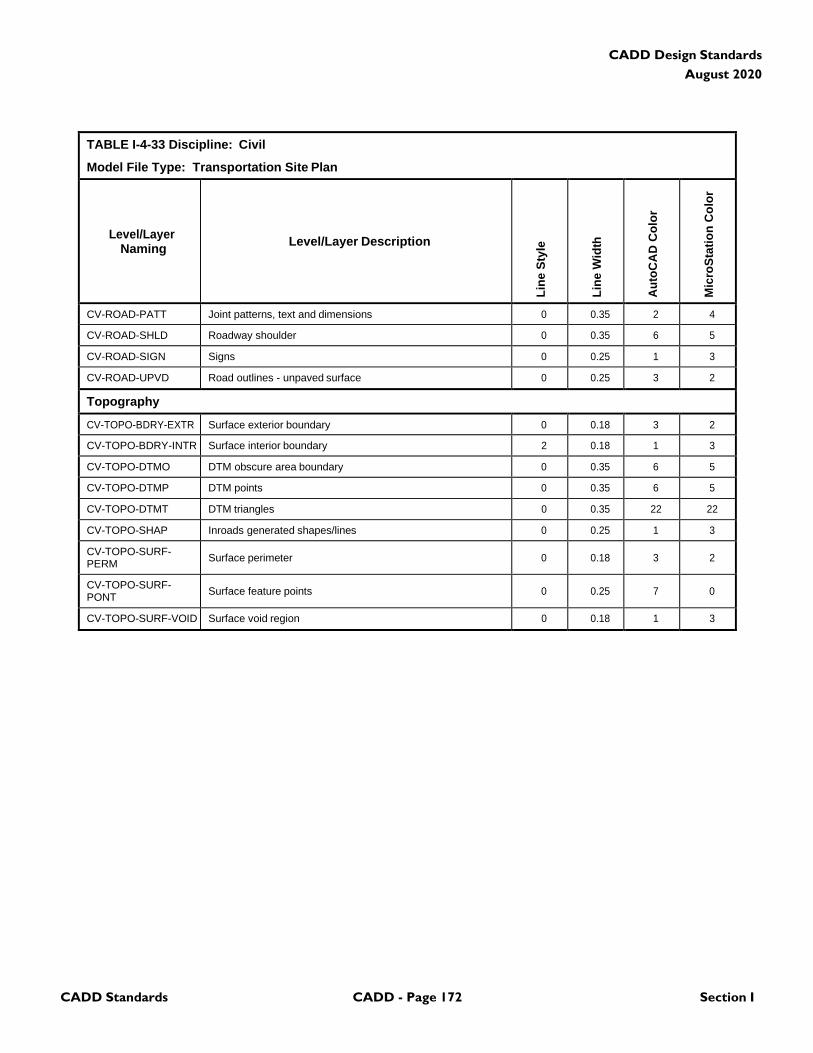
CADD Standards CADD - Page 172 Section I
CADD Design Standards
August 2020
TABLE I-4-33 Discipline: Civil
Model File Type: Transportation Site Plan
Level/Layer
Naming
Level/Layer Description
Lin
e S
tyle
Lin
e W
idth
Au
toC
AD
Co
lor
Mic
roS
tati
on
Co
lor
CV-ROAD-PATT Joint patterns, text and dimensions 0 0.35 2 4
CV-ROAD-SHLD Roadway shoulder 0 0.35 6 5
CV-ROAD-SIGN Signs 0 0.25 1 3
CV-ROAD-UPVD Road outlines - unpaved surface 0 0.25 3 2
Topography
CV-TOPO-BDRY-EXTR Surface exterior boundary 0 0.18 3 2
CV-TOPO-BDRY-INTR Surface interior boundary 2 0.18 1 3
CV-TOPO-DTMO DTM obscure area boundary 0 0.35 6 5
CV-TOPO-DTMP DTM points 0 0.35 6 5
CV-TOPO-DTMT DTM triangles 0 0.35 22 22
CV-TOPO-SHAP Inroads generated shapes/lines 0 0.25 1 3
CV-TOPO-SURF- PERM
Surface perimeter
0
0.18
3
2
CV-TOPO-SURF- PONT
Surface feature points
0
0.25
7
0
CV-TOPO-SURF-VOID Surface void region 0 0.18 1 3
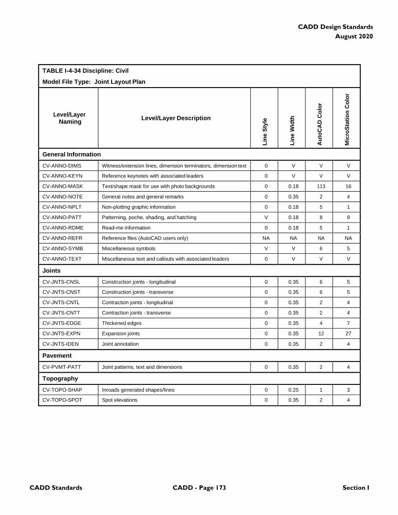
CADD Standards CADD - Page 173 Section I
CADD Design Standards
August 2020
TABLE I-4-34 Discipline: Civil
Model File Type: Joint Layout Plan
Level/Layer
Naming
Level/Layer Description
Lin
e S
tyle
Lin
e W
idth
Au
toC
AD
Co
lor
Mic
roS
tati
on
Co
lor
General Information
CV-ANNO-DIMS Witness/extension lines, dimension terminators, dimension text 0 V V V
CV-ANNO-KEYN Reference keynotes with associated leaders 0 V V V
CV-ANNO-MASK Text/shape mask for use with photo backgrounds 0 0.18 113 16
CV-ANNO-NOTE General notes and general remarks 0 0.35 2 4
CV-ANNO-NPLT Non-plotting graphic information 0 0.18 5 1
CV-ANNO-PATT Patterning, poche, shading, and hatching V 0.18 8 9
CV-ANNO-RDME Read-me information 0 0.18 5 1
CV-ANNO-REFR Reference files (AutoCAD users only) NA NA NA NA
CV-ANNO-SYMB Miscellaneous symbols V V 6 5
CV-ANNO-TEXT Miscellaneous text and callouts with associated leaders 0 V V V
Joints
CV-JNTS-CNSL Construction joints - longitudinal 0 0.35 6 5
CV-JNTS-CNST Construction joints - transverse 0 0.35 6 5
CV-JNTS-CNTL Contraction joints - longitudinal 0 0.35 2 4
CV-JNTS-CNTT Contraction joints - transverse 0 0.35 2 4
CV-JNTS-EDGE Thickened edges 0 0.35 4 7
CV-JNTS-EXPN Expansion joints 0 0.35 12 27
CV-JNTS-IDEN Joint annotation 0 0.35 2 4
Pavement
CV-PVMT-PATT Joint patterns, text and dimensions 0 0.35 2 4
Topography
CV-TOPO-SHAP Inroads generated shapes/lines 0 0.25 1 3
CV-TOPO-SPOT Spot elevations 0 0.35 2 4
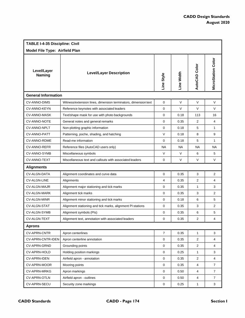
CADD Standards CADD - Page 174 Section I
CADD Design Standards
August 2020
TABLE I-4-35 Discipline: Civil
Model File Type: Airfield Plan
Level/Layer
Naming
Level/Layer Description
Lin
e S
tyle
Lin
e W
idth
Au
toC
AD
Co
lor
Mic
roS
tati
on
Co
lor
General Information
CV-ANNO-DIMS Witness/extension lines, dimension terminators, dimension text 0 V V V
CV-ANNO-KEYN Reference keynotes with associated leaders 0 V V V
CV-ANNO-MASK Text/shape mask for use with photo backgrounds 0 0.18 113 16
CV-ANNO-NOTE General notes and general remarks 0 0.35 2 4
CV-ANNO-NPLT Non-plotting graphic information 0 0.18 5 1
CV-ANNO-PATT Patterning, poche, shading, and hatching V 0.18 8 9
CV-ANNO-RDME Read-me information 0 0.18 5 1
CV-ANNO-REFR Reference files (AutoCAD users only) NA NA NA NA
CV-ANNO-SYMB Miscellaneous symbols V V 6 5
CV-ANNO-TEXT Miscellaneous text and callouts with associated leaders 0 V V V
Alignments
CV-ALGN-DATA Alignment coordinates and curve data 0 0.35 3 2
CV-ALGN-LINE Alignments 4 0.35 2 4
CV-ALGN-MAJR Alignment major stationing and tick marks 0 0.35 1 3
CV-ALGN-MARK Alignment tick marks 0 0.35 3 2
CV-ALGN-MINR Alignment minor stationing and tick marks 0 0.18 6 5
CV-ALGN-STAT Alignment stationing and tick marks, alignment PI stations 0 0.35 3 2
CV-ALGN-SYMB Alignment symbols (PIs) 0 0.35 6 5
CV-ALGN-TEXT Alignment text, annotation with associated leaders 0 0.35 2 4
Aprons
CV-APRN-CNTR Apron centerlines 7 0.35 1 3
CV-APRN-CNTR-IDEN Apron centerline annotation 0 0.35 2 4
CV-APRN-GRND Grounding points 0 0.35 2 4
CV-APRN-HOLD Holding position markings 0 0.25 1 3
CV-APRN-IDEN Airfield apron - annotation 0 0.35 2 4
CV-APRN-MOOR Mooring points 0 0.35 4 7
CV-APRN-MRKG Apron markings 0 0.50 4 7
CV-APRN-OTLN Airfield apron - outlines 0 0.50 4 7
CV-APRN-SECU Security zone markings 0 0.25 1 3
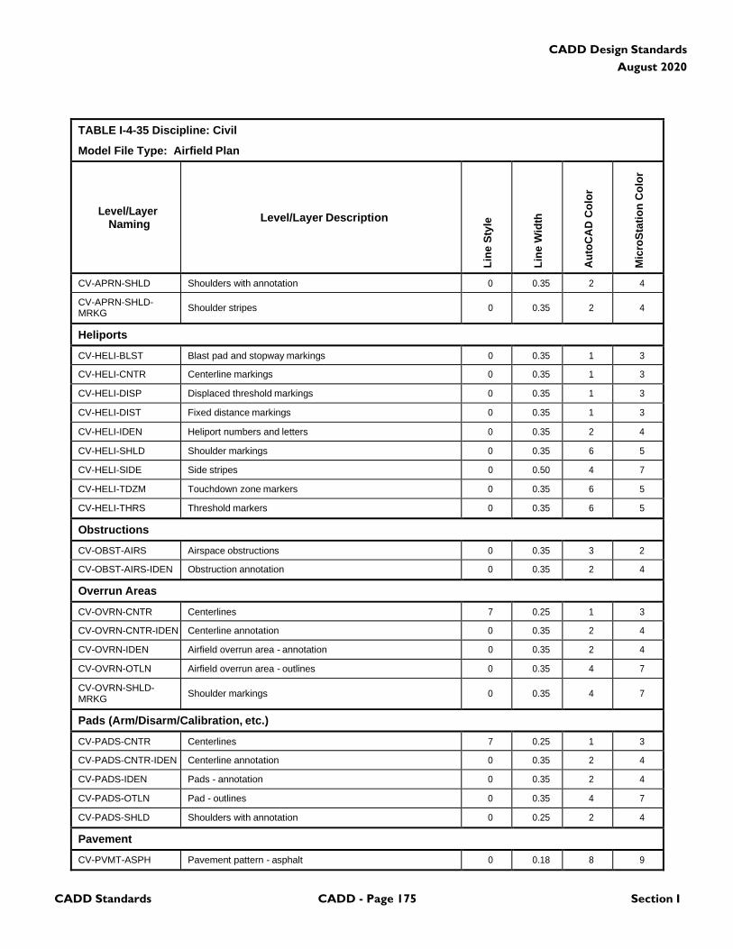
CADD Standards CADD - Page 175 Section I
CADD Design Standards
August 2020
TABLE I-4-35 Discipline: Civil
Model File Type: Airfield Plan
Level/Layer
Naming
Level/Layer Description
Lin
e S
tyle
Lin
e W
idth
Au
toC
AD
Co
lor
Mic
roS
tati
on
Co
lor
CV-APRN-SHLD Shoulders with annotation 0 0.35 2 4
CV-APRN-SHLD- MRKG
Shoulder stripes
0
0.35
2
4
Heliports
CV-HELI-BLST Blast pad and stopway markings 0 0.35 1 3
CV-HELI-CNTR Centerline markings 0 0.35 1 3
CV-HELI-DISP Displaced threshold markings 0 0.35 1 3
CV-HELI-DIST Fixed distance markings 0 0.35 1 3
CV-HELI-IDEN Heliport numbers and letters 0 0.35 2 4
CV-HELI-SHLD Shoulder markings 0 0.35 6 5
CV-HELI-SIDE Side stripes 0 0.50 4 7
CV-HELI-TDZM Touchdown zone markers 0 0.35 6 5
CV-HELI-THRS Threshold markers 0 0.35 6 5
Obstructions
CV-OBST-AIRS Airspace obstructions 0 0.35 3 2
CV-OBST-AIRS-IDEN Obstruction annotation 0 0.35 2 4
Overrun Areas
CV-OVRN-CNTR Centerlines 7 0.25 1 3
CV-OVRN-CNTR-IDEN Centerline annotation 0 0.35 2 4
CV-OVRN-IDEN Airfield overrun area - annotation 0 0.35 2 4
CV-OVRN-OTLN Airfield overrun area - outlines 0 0.35 4 7
CV-OVRN-SHLD- MRKG
Shoulder markings
0
0.35
4
7
Pads (Arm/Disarm/Calibration, etc.)
CV-PADS-CNTR Centerlines 7 0.25 1 3
CV-PADS-CNTR-IDEN Centerline annotation 0 0.35 2 4
CV-PADS-IDEN Pads - annotation 0 0.35 2 4
CV-PADS-OTLN Pad - outlines 0 0.35 4 7
CV-PADS-SHLD Shoulders with annotation 0 0.25 2 4
Pavement
CV-PVMT-ASPH Pavement pattern - asphalt 0 0.18 8 9
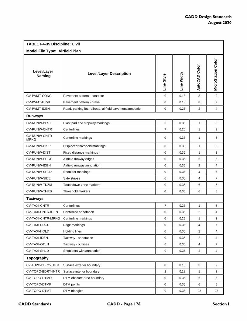
CADD Standards CADD - Page 176 Section I
CADD Design Standards
August 2020
TABLE I-4-35 Discipline: Civil
Model File Type: Airfield Plan
Level/Layer
Naming
Level/Layer Description
Lin
e S
tyle
Lin
e W
idth
Au
toC
AD
Co
lor
Mic
roS
tati
on
Co
lor
CV-PVMT-CONC Pavement pattern - concrete 0 0.18 8 9
CV-PVMT-GRVL Pavement pattern - gravel 0 0.18 8 9
CV-PVMT-IDEN Road, parking lot, railroad, airfield pavement annotation 0 0.25 2 4
Runways
CV-RUNW-BLST Blast pad and stopway markings 0 0.35 1 3
CV-RUNW-CNTR Centerlines 7 0.25 1 3
CV-RUNW-CNTR- MRKG
Centerline markings
0
0.35
1
3
CV-RUNW-DISP Displaced threshold markings 0 0.35 1 3
CV-RUNW-DIST Fixed distance markings 0 0.35 1 3
CV-RUNW-EDGE Airfield runway edges 0 0.35 6 5
CV-RUNW-IDEN Airfield runway annotation 0 0.35 2 4
CV-RUNW-SHLD Shoulder markings 0 0.35 4 7
CV-RUNW-SIDE Side stripes 0 0.35 4 7
CV-RUNW-TDZM Touchdown zone markers 0 0.35 6 5
CV-RUNW-THRS Threshold markers 0 0.35 6 5
Taxiways
CV-TAXI-CNTR Centerlines 7 0.25 1 3
CV-TAXI-CNTR-IDEN Centerline annotation 0 0.35 2 4
CV-TAXI-CNTR-MRKG Centerline markings 0 0.25 1 3
CV-TAXI-EDGE Edge markings 0 0.35 4 7
CV-TAXI-HOLD Holding lines 0 0.35 2 4
CV-TAXI-IDEN Taxiway - annotation 0 0.35 2 4
CV-TAXI-OTLN Taxiway - outlines 0 0.35 4 7
CV-TAXI-SHLD Shoulders with annotation 0 0.35 2 4
Topography
CV-TOPO-BDRY-EXTR Surface exterior boundary 0 0.18 3 2
CV-TOPO-BDRY-INTR Surface interior boundary 2 0.18 1 3
CV-TOPO-DTMO DTM obscure area boundary 0 0.35 6 5
CV-TOPO-DTMP DTM points 0 0.35 6 5
CV-TOPO-DTMT DTM triangles 0 0.35 22 22
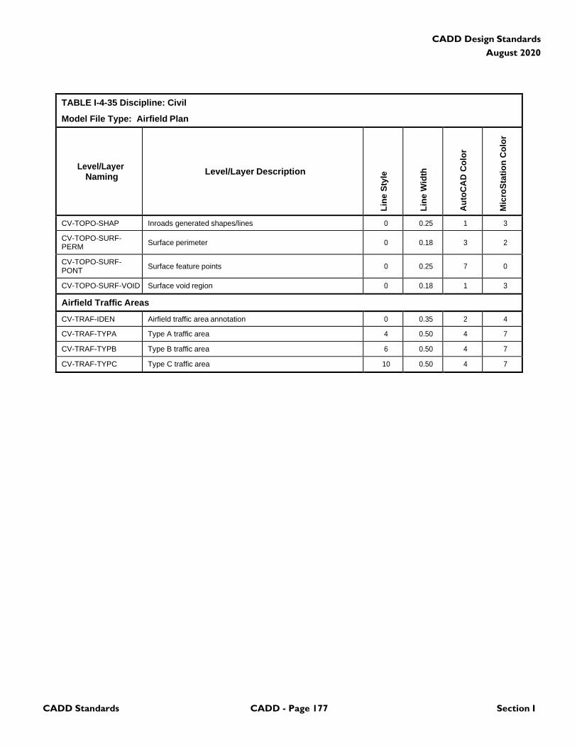
CADD Standards CADD - Page 177 Section I
CADD Design Standards
August 2020
TABLE I-4-35 Discipline: Civil
Model File Type: Airfield Plan
Level/Layer
Naming
Level/Layer Description
Lin
e S
tyle
Lin
e W
idth
Au
toC
AD
Co
lor
Mic
roS
tati
on
Co
lor
CV-TOPO-SHAP Inroads generated shapes/lines 0 0.25 1 3
CV-TOPO-SURF- PERM
Surface perimeter
0
0.18
3
2
CV-TOPO-SURF- PONT
Surface feature points
0
0.25
7
0
CV-TOPO-SURF-VOID Surface void region 0 0.18 1 3
Airfield Traffic Areas
CV-TRAF-IDEN Airfield traffic area annotation 0 0.35 2 4
CV-TRAF-TYPA Type A traffic area 4 0.50 4 7
CV-TRAF-TYPB Type B traffic area 6 0.50 4 7
CV-TRAF-TYPC Type C traffic area 10 0.50 4 7
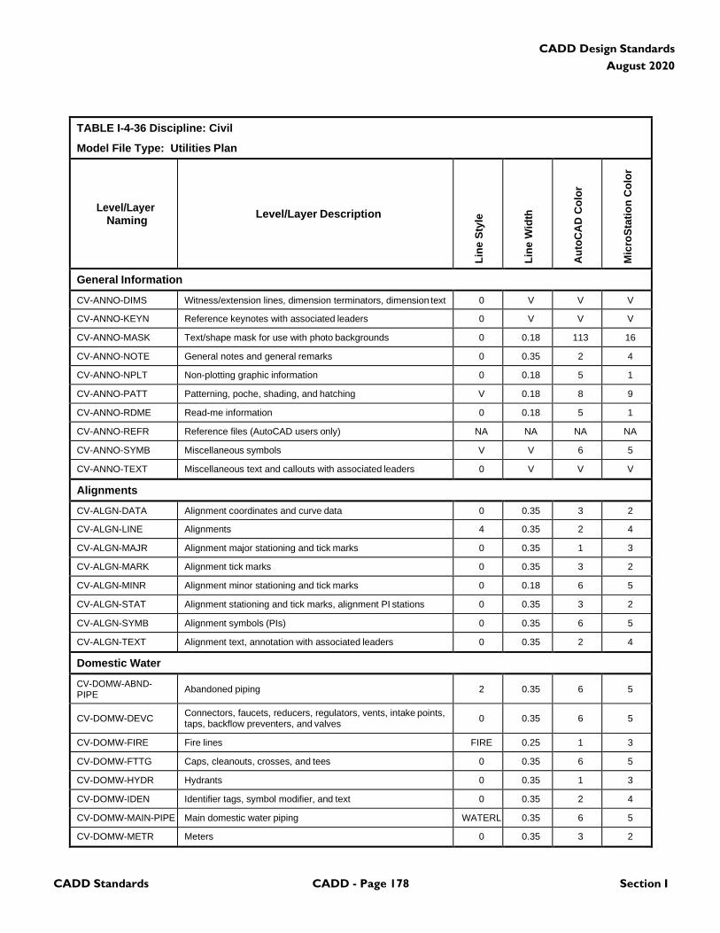
CADD Standards CADD - Page 178 Section I
CADD Design Standards
August 2020
TABLE I-4-36 Discipline: Civil
Model File Type: Utilities Plan
Level/Layer
Naming
Level/Layer Description
Lin
e S
tyle
Lin
e W
idth
Au
toC
AD
Co
lor
Mic
roS
tati
on
Co
lor
General Information
CV-ANNO-DIMS Witness/extension lines, dimension terminators, dimension text 0 V V V
CV-ANNO-KEYN Reference keynotes with associated leaders 0 V V V
CV-ANNO-MASK Text/shape mask for use with photo backgrounds 0 0.18 113 16
CV-ANNO-NOTE General notes and general remarks 0 0.35 2 4
CV-ANNO-NPLT Non-plotting graphic information 0 0.18 5 1
CV-ANNO-PATT Patterning, poche, shading, and hatching V 0.18 8 9
CV-ANNO-RDME Read-me information 0 0.18 5 1
CV-ANNO-REFR Reference files (AutoCAD users only) NA NA NA NA
CV-ANNO-SYMB Miscellaneous symbols V V 6 5
CV-ANNO-TEXT Miscellaneous text and callouts with associated leaders 0 V V V
Alignments
CV-ALGN-DATA Alignment coordinates and curve data 0 0.35 3 2
CV-ALGN-LINE Alignments 4 0.35 2 4
CV-ALGN-MAJR Alignment major stationing and tick marks 0 0.35 1 3
CV-ALGN-MARK Alignment tick marks 0 0.35 3 2
CV-ALGN-MINR Alignment minor stationing and tick marks 0 0.18 6 5
CV-ALGN-STAT Alignment stationing and tick marks, alignment PI stations 0 0.35 3 2
CV-ALGN-SYMB Alignment symbols (PIs) 0 0.35 6 5
CV-ALGN-TEXT Alignment text, annotation with associated leaders 0 0.35 2 4
Domestic Water
CV-DOMW-ABND- PIPE
Abandoned piping
2
0.35
6
5
CV-DOMW-DEVC Connectors, faucets, reducers, regulators, vents, intake points, taps, backflow preventers, and valves
0
0.35
6
5
CV-DOMW-FIRE Fire lines FIRE 0.25 1 3
CV-DOMW-FTTG Caps, cleanouts, crosses, and tees 0 0.35 6 5
CV-DOMW-HYDR Hydrants 0 0.35 1 3
CV-DOMW-IDEN Identifier tags, symbol modifier, and text 0 0.35 2 4
CV-DOMW-MAIN-PIPE Main domestic water piping WATERL 0.35 6 5
CV-DOMW-METR Meters 0 0.35 3 2
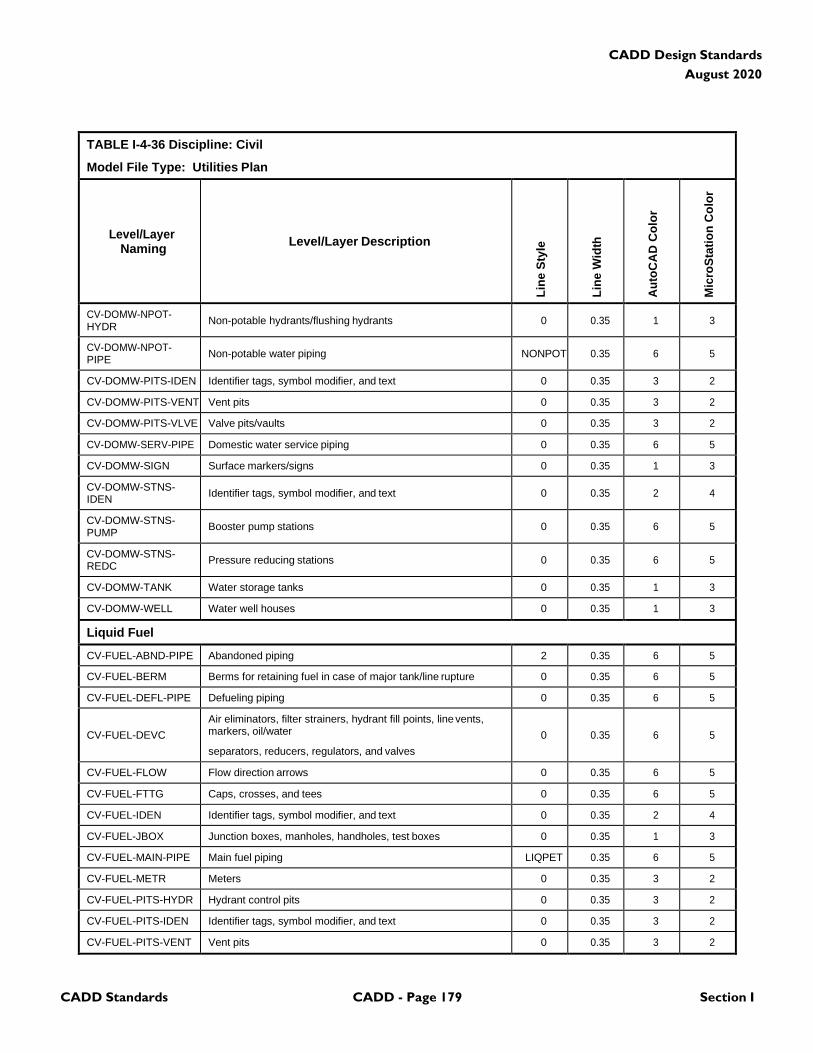
CADD Standards CADD - Page 179 Section I
CADD Design Standards
August 2020
TABLE I-4-36 Discipline: Civil
Model File Type: Utilities Plan
Level/Layer
Naming
Level/Layer Description
Lin
e S
tyle
Lin
e W
idth
Au
toC
AD
Co
lor
Mic
roS
tati
on
Co
lor
CV-DOMW-NPOT- HYDR
Non-potable hydrants/flushing hydrants
0
0.35
1
3
CV-DOMW-NPOT- PIPE
Non-potable water piping
NONPOT
0.35
6
5
CV-DOMW-PITS-IDEN Identifier tags, symbol modifier, and text 0 0.35 3 2
CV-DOMW-PITS-VENT Vent pits 0 0.35 3 2
CV-DOMW-PITS-VLVE Valve pits/vaults 0 0.35 3 2
CV-DOMW-SERV-PIPE Domestic water service piping 0 0.35 6 5
CV-DOMW-SIGN Surface markers/signs 0 0.35 1 3
CV-DOMW-STNS- IDEN
Identifier tags, symbol modifier, and text
0
0.35
2
4
CV-DOMW-STNS- PUMP
Booster pump stations
0
0.35
6
5
CV-DOMW-STNS- REDC
Pressure reducing stations
0
0.35
6
5
CV-DOMW-TANK Water storage tanks 0 0.35 1 3
CV-DOMW-WELL Water well houses 0 0.35 1 3
Liquid Fuel
CV-FUEL-ABND-PIPE Abandoned piping 2 0.35 6 5
CV-FUEL-BERM Berms for retaining fuel in case of major tank/line rupture 0 0.35 6 5
CV-FUEL-DEFL-PIPE Defueling piping 0 0.35 6 5
CV-FUEL-DEVC
Air eliminators, filter strainers, hydrant fill points, line vents, markers, oil/water
separators, reducers, regulators, and valves
0
0.35
6
5
CV-FUEL-FLOW Flow direction arrows 0 0.35 6 5
CV-FUEL-FTTG Caps, crosses, and tees 0 0.35 6 5
CV-FUEL-IDEN Identifier tags, symbol modifier, and text 0 0.35 2 4
CV-FUEL-JBOX Junction boxes, manholes, handholes, test boxes 0 0.35 1 3
CV-FUEL-MAIN-PIPE Main fuel piping LIQPET 0.35 6 5
CV-FUEL-METR Meters 0 0.35 3 2
CV-FUEL-PITS-HYDR Hydrant control pits 0 0.35 3 2
CV-FUEL-PITS-IDEN Identifier tags, symbol modifier, and text 0 0.35 3 2
CV-FUEL-PITS-VENT Vent pits 0 0.35 3 2
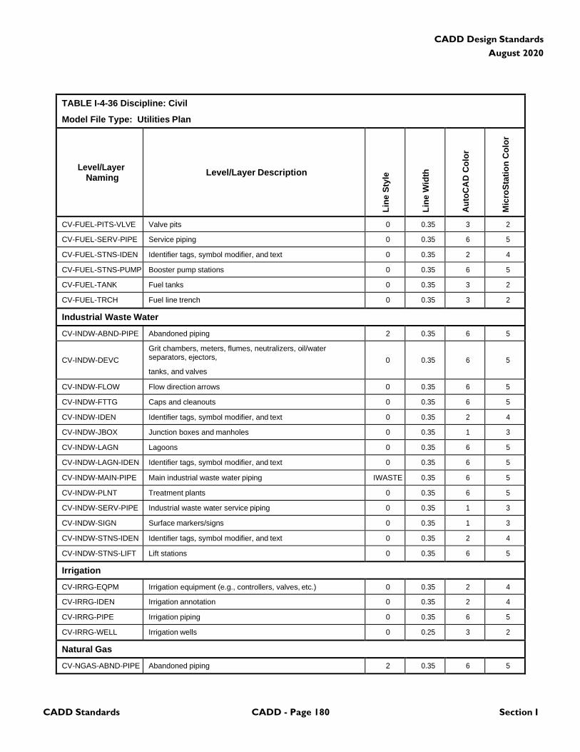
CADD Standards CADD - Page 180 Section I
CADD Design Standards
August 2020
TABLE I-4-36 Discipline: Civil
Model File Type: Utilities Plan
Level/Layer
Naming
Level/Layer Description
Lin
e S
tyle
Lin
e W
idth
Au
toC
AD
Co
lor
Mic
roS
tati
on
Co
lor
CV-FUEL-PITS-VLVE Valve pits 0 0.35 3 2
CV-FUEL-SERV-PIPE Service piping 0 0.35 6 5
CV-FUEL-STNS-IDEN Identifier tags, symbol modifier, and text 0 0.35 2 4
CV-FUEL-STNS-PUMP Booster pump stations 0 0.35 6 5
CV-FUEL-TANK Fuel tanks 0 0.35 3 2
CV-FUEL-TRCH Fuel line trench 0 0.35 3 2
Industrial Waste Water
CV-INDW-ABND-PIPE Abandoned piping 2 0.35 6 5
CV-INDW-DEVC
Grit chambers, meters, flumes, neutralizers, oil/water separators, ejectors,
tanks, and valves
0
0.35
6
5
CV-INDW-FLOW Flow direction arrows 0 0.35 6 5
CV-INDW-FTTG Caps and cleanouts 0 0.35 6 5
CV-INDW-IDEN Identifier tags, symbol modifier, and text 0 0.35 2 4
CV-INDW-JBOX Junction boxes and manholes 0 0.35 1 3
CV-INDW-LAGN Lagoons 0 0.35 6 5
CV-INDW-LAGN-IDEN Identifier tags, symbol modifier, and text 0 0.35 6 5
CV-INDW-MAIN-PIPE Main industrial waste water piping IWASTE 0.35 6 5
CV-INDW-PLNT Treatment plants 0 0.35 6 5
CV-INDW-SERV-PIPE Industrial waste water service piping 0 0.35 1 3
CV-INDW-SIGN Surface markers/signs 0 0.35 1 3
CV-INDW-STNS-IDEN Identifier tags, symbol modifier, and text 0 0.35 2 4
CV-INDW-STNS-LIFT Lift stations 0 0.35 6 5
Irrigation
CV-IRRG-EQPM Irrigation equipment (e.g., controllers, valves, etc.) 0 0.35 2 4
CV-IRRG-IDEN Irrigation annotation 0 0.35 2 4
CV-IRRG-PIPE Irrigation piping 0 0.35 6 5
CV-IRRG-WELL Irrigation wells 0 0.25 3 2
Natural Gas
CV-NGAS-ABND-PIPE Abandoned piping 2 0.35 6 5
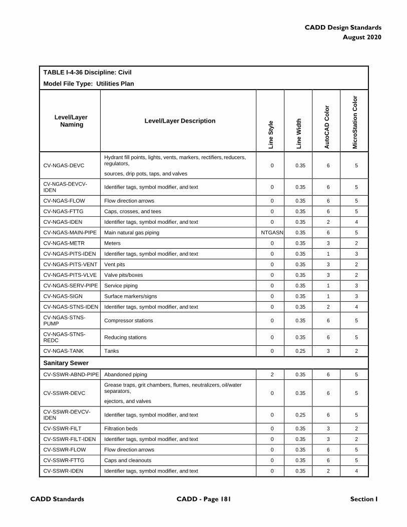
CADD Standards CADD - Page 181 Section I
CADD Design Standards
August 2020
TABLE I-4-36 Discipline: Civil
Model File Type: Utilities Plan
Level/Layer
Naming
Level/Layer Description
Lin
e S
tyle
Lin
e W
idth
Au
toC
AD
Co
lor
Mic
roS
tati
on
Co
lor
CV-NGAS-DEVC
Hydrant fill points, lights, vents, markers, rectifiers, reducers, regulators,
sources, drip pots, taps, and valves
0
0.35
6
5
CV-NGAS-DEVCV- IDEN
Identifier tags, symbol modifier, and text
0
0.35
6
5
CV-NGAS-FLOW Flow direction arrows 0 0.35 6 5
CV-NGAS-FTTG Caps, crosses, and tees 0 0.35 6 5
CV-NGAS-IDEN Identifier tags, symbol modifier, and text 0 0.35 2 4
CV-NGAS-MAIN-PIPE Main natural gas piping NTGASN 0.35 6 5
CV-NGAS-METR Meters 0 0.35 3 2
CV-NGAS-PITS-IDEN Identifier tags, symbol modifier, and text 0 0.35 1 3
CV-NGAS-PITS-VENT Vent pits 0 0.35 3 2
CV-NGAS-PITS-VLVE Valve pits/boxes 0 0.35 3 2
CV-NGAS-SERV-PIPE Service piping 0 0.35 1 3
CV-NGAS-SIGN Surface markers/signs 0 0.35 1 3
CV-NGAS-STNS-IDEN Identifier tags, symbol modifier, and text 0 0.35 2 4
CV-NGAS-STNS- PUMP
Compressor stations
0
0.35
6
5
CV-NGAS-STNS- REDC
Reducing stations
0
0.35
6
5
CV-NGAS-TANK Tanks 0 0.25 3 2
Sanitary Sewer
CV-SSWR-ABND-PIPE Abandoned piping 2 0.35 6 5
CV-SSWR-DEVC
Grease traps, grit chambers, flumes, neutralizers, oil/water separators,
ejectors, and valves
0
0.35
6
5
CV-SSWR-DEVCV- IDEN
Identifier tags, symbol modifier, and text
0
0.25
6
5
CV-SSWR-FILT Filtration beds 0 0.35 3 2
CV-SSWR-FILT-IDEN Identifier tags, symbol modifier, and text 0 0.35 3 2
CV-SSWR-FLOW Flow direction arrows 0 0.35 6 5
CV-SSWR-FTTG Caps and cleanouts 0 0.35 6 5
CV-SSWR-IDEN Identifier tags, symbol modifier, and text 0 0.35 2 4
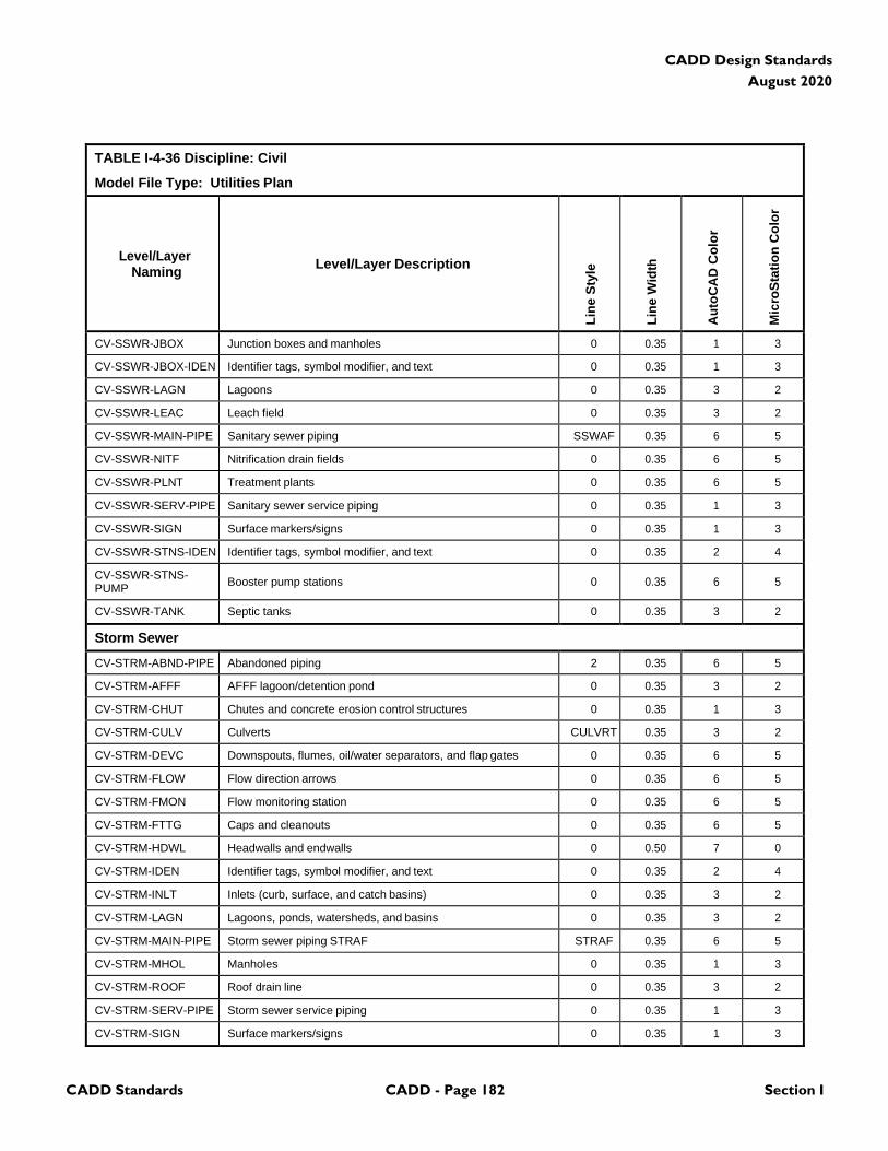
CADD Standards CADD - Page 182 Section I
CADD Design Standards
August 2020
TABLE I-4-36 Discipline: Civil
Model File Type: Utilities Plan
Level/Layer
Naming
Level/Layer Description
Lin
e S
tyle
Lin
e W
idth
Au
toC
AD
Co
lor
Mic
roS
tati
on
Co
lor
CV-SSWR-JBOX Junction boxes and manholes 0 0.35 1 3
CV-SSWR-JBOX-IDEN Identifier tags, symbol modifier, and text 0 0.35 1 3
CV-SSWR-LAGN Lagoons 0 0.35 3 2
CV-SSWR-LEAC Leach field 0 0.35 3 2
CV-SSWR-MAIN-PIPE Sanitary sewer piping SSWAF 0.35 6 5
CV-SSWR-NITF Nitrification drain fields 0 0.35 6 5
CV-SSWR-PLNT Treatment plants 0 0.35 6 5
CV-SSWR-SERV-PIPE Sanitary sewer service piping 0 0.35 1 3
CV-SSWR-SIGN Surface markers/signs 0 0.35 1 3
CV-SSWR-STNS-IDEN Identifier tags, symbol modifier, and text 0 0.35 2 4
CV-SSWR-STNS- PUMP
Booster pump stations
0
0.35
6
5
CV-SSWR-TANK Septic tanks 0 0.35 3 2
Storm Sewer
CV-STRM-ABND-PIPE Abandoned piping 2 0.35 6 5
CV-STRM-AFFF AFFF lagoon/detention pond 0 0.35 3 2
CV-STRM-CHUT Chutes and concrete erosion control structures 0 0.35 1 3
CV-STRM-CULV Culverts CULVRT 0.35 3 2
CV-STRM-DEVC Downspouts, flumes, oil/water separators, and flap gates 0 0.35 6 5
CV-STRM-FLOW Flow direction arrows 0 0.35 6 5
CV-STRM-FMON Flow monitoring station 0 0.35 6 5
CV-STRM-FTTG Caps and cleanouts 0 0.35 6 5
CV-STRM-HDWL Headwalls and endwalls 0 0.50 7 0
CV-STRM-IDEN Identifier tags, symbol modifier, and text 0 0.35 2 4
CV-STRM-INLT Inlets (curb, surface, and catch basins) 0 0.35 3 2
CV-STRM-LAGN Lagoons, ponds, watersheds, and basins 0 0.35 3 2
CV-STRM-MAIN-PIPE Storm sewer piping STRAF STRAF 0.35 6 5
CV-STRM-MHOL Manholes 0 0.35 1 3
CV-STRM-ROOF Roof drain line 0 0.35 3 2
CV-STRM-SERV-PIPE Storm sewer service piping 0 0.35 1 3
CV-STRM-SIGN Surface markers/signs 0 0.35 1 3
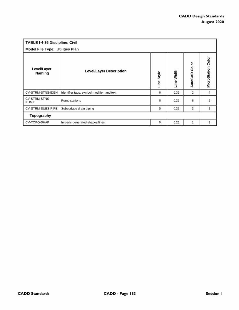
CADD Standards CADD - Page 183 Section I
CADD Design Standards
August 2020
TABLE I-4-36 Discipline: Civil
Model File Type: Utilities Plan
Level/Layer
Naming
Level/Layer Description
Lin
e S
tyle
Lin
e W
idth
Au
toC
AD
Co
lor
Mic
roS
tati
on
Co
lor
CV-STRM-STNS-IDEN Identifier tags, symbol modifier, and text 0 0.35 2 4
CV-STRM-STNS- PUMP
Pump stations
0
0.35
6
5
CV-STRM-SUBS-PIPE Subsurface drain piping 0 0.35 3 2
Topography
CV-TOPO-SHAP Inroads generated shapes/lines 0 0.25 1 3
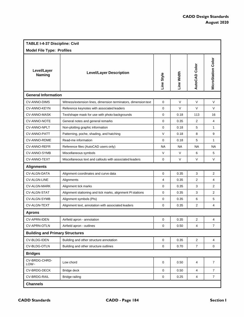
CADD Standards CADD - Page 184 Section I
CADD Design Standards
August 2020
TABLE I-4-37 Discipline: Civil
Model File Type: Profiles
Level/Layer
Naming
Level/Layer Description
Lin
e S
tyle
Lin
e W
idth
Au
toC
AD
Co
lor
Mic
roS
tati
on
Co
lor
General Information
CV-ANNO-DIMS Witness/extension lines, dimension terminators, dimension text 0 V V V
CV-ANNO-KEYN Reference keynotes with associated leaders 0 V V V
CV-ANNO-MASK Text/shape mask for use with photo backgrounds 0 0.18 113 16
CV-ANNO-NOTE General notes and general remarks 0 0.35 2 4
CV-ANNO-NPLT Non-plotting graphic information 0 0.18 5 1
CV-ANNO-PATT Patterning, poche, shading, and hatching V 0.18 8 9
CV-ANNO-RDME Read-me information 0 0.18 5 1
CV-ANNO-REFR Reference files (AutoCAD users only) NA NA NA NA
CV-ANNO-SYMB Miscellaneous symbols V V 6 5
CV-ANNO-TEXT Miscellaneous text and callouts with associated leaders 0 V V V
Alignments
CV-ALGN-DATA Alignment coordinates and curve data 0 0.35 3 2
CV-ALGN-LINE Alignments 4 0.35 2 4
CV-ALGN-MARK Alignment tick marks 0 0.35 3 2
CV-ALGN-STAT Alignment stationing and tick marks, alignment PI stations 0 0.35 3 2
CV-ALGN-SYMB Alignment symbols (PIs) 0 0.35 6 5
CV-ALGN-TEXT Alignment text, annotation with associated leaders 0 0.35 2 4
Aprons
CV-APRN-IDEN Airfield apron - annotation 0 0.35 2 4
CV-APRN-OTLN Airfield apron - outlines 0 0.50 4 7
Building and Primary Structures
CV-BLDG-IDEN Building and other structure annotation 0 0.35 2 4
CV-BLDG-OTLN Building and other structure outlines 0 0.70 7 0
Bridges
CV-BRDG-CHRD- LOW~
Low chord
0
0.50
4
7
CV-BRDG-DECK Bridge deck 0 0.50 4 7
CV-BRDG-RAIL Bridge railing 0 0.25 4 7
Channels
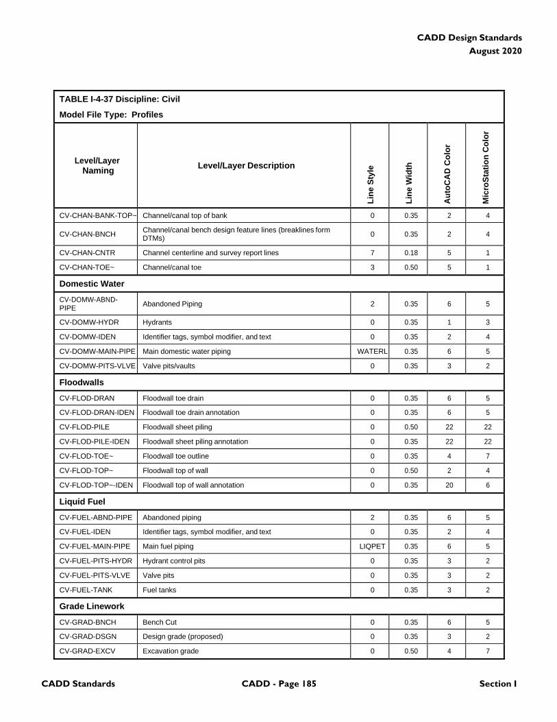
CADD Standards CADD - Page 185 Section I
CADD Design Standards
August 2020
TABLE I-4-37 Discipline: Civil
Model File Type: Profiles
Level/Layer
Naming
Level/Layer Description
Lin
e S
tyle
Lin
e W
idth
Au
toC
AD
Co
lor
Mic
roS
tati
on
Co
lor
CV-CHAN-BANK-TOP~ Channel/canal top of bank 0 0.35 2 4
CV-CHAN-BNCH Channel/canal bench design feature lines (breaklines form DTMs)
0
0.35
2
4
CV-CHAN-CNTR Channel centerline and survey report lines 7 0.18 5 1
CV-CHAN-TOE~ Channel/canal toe 3 0.50 5 1
Domestic Water
CV-DOMW-ABND- PIPE
Abandoned Piping
2
0.35
6
5
CV-DOMW-HYDR Hydrants 0 0.35 1 3
CV-DOMW-IDEN Identifier tags, symbol modifier, and text 0 0.35 2 4
CV-DOMW-MAIN-PIPE Main domestic water piping WATERL 0.35 6 5
CV-DOMW-PITS-VLVE Valve pits/vaults 0 0.35 3 2
Floodwalls
CV-FLOD-DRAN Floodwall toe drain 0 0.35 6 5
CV-FLOD-DRAN-IDEN Floodwall toe drain annotation 0 0.35 6 5
CV-FLOD-PILE Floodwall sheet piling 0 0.50 22 22
CV-FLOD-PILE-IDEN Floodwall sheet piling annotation 0 0.35 22 22
CV-FLOD-TOE~ Floodwall toe outline 0 0.35 4 7
CV-FLOD-TOP~ Floodwall top of wall 0 0.50 2 4
CV-FLOD-TOP~-IDEN Floodwall top of wall annotation 0 0.35 20 6
Liquid Fuel
CV-FUEL-ABND-PIPE Abandoned piping 2 0.35 6 5
CV-FUEL-IDEN Identifier tags, symbol modifier, and text 0 0.35 2 4
CV-FUEL-MAIN-PIPE Main fuel piping LIQPET 0.35 6 5
CV-FUEL-PITS-HYDR Hydrant control pits 0 0.35 3 2
CV-FUEL-PITS-VLVE Valve pits 0 0.35 3 2
CV-FUEL-TANK Fuel tanks 0 0.35 3 2
Grade Linework
CV-GRAD-BNCH Bench Cut 0 0.35 6 5
CV-GRAD-DSGN Design grade (proposed) 0 0.35 3 2
CV-GRAD-EXCV Excavation grade 0 0.50 4 7
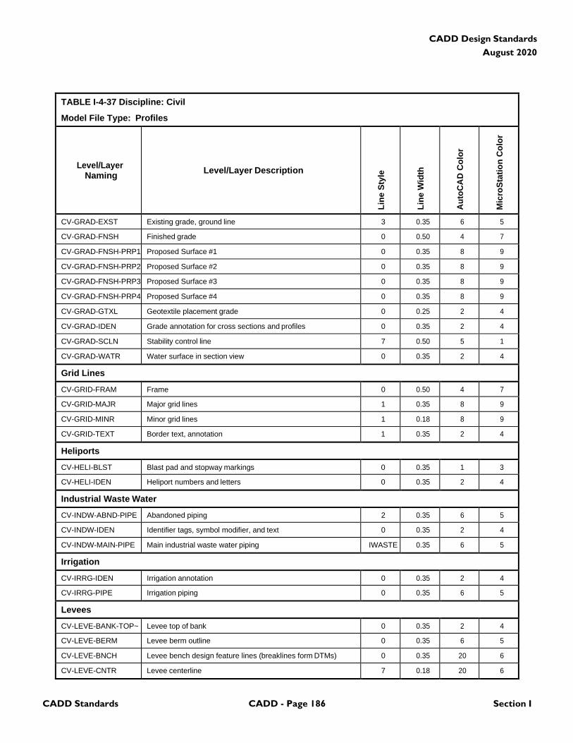
CADD Standards CADD - Page 186 Section I
CADD Design Standards
August 2020
TABLE I-4-37 Discipline: Civil
Model File Type: Profiles
Level/Layer
Naming
Level/Layer Description
Lin
e S
tyle
Lin
e W
idth
Au
toC
AD
Co
lor
Mic
roS
tati
on
Co
lor
CV-GRAD-EXST Existing grade, ground line 3 0.35 6 5
CV-GRAD-FNSH Finished grade 0 0.50 4 7
CV-GRAD-FNSH-PRP1 Proposed Surface #1 0 0.35 8 9
CV-GRAD-FNSH-PRP2 Proposed Surface #2 0 0.35 8 9
CV-GRAD-FNSH-PRP3 Proposed Surface #3 0 0.35 8 9
CV-GRAD-FNSH-PRP4 Proposed Surface #4 0 0.35 8 9
CV-GRAD-GTXL Geotextile placement grade 0 0.25 2 4
CV-GRAD-IDEN Grade annotation for cross sections and profiles 0 0.35 2 4
CV-GRAD-SCLN Stability control line 7 0.50 5 1
CV-GRAD-WATR Water surface in section view 0 0.35 2 4
Grid Lines
CV-GRID-FRAM Frame 0 0.50 4 7
CV-GRID-MAJR Major grid lines 1 0.35 8 9
CV-GRID-MINR Minor grid lines 1 0.18 8 9
CV-GRID-TEXT Border text, annotation 1 0.35 2 4
Heliports
CV-HELI-BLST Blast pad and stopway markings 0 0.35 1 3
CV-HELI-IDEN Heliport numbers and letters 0 0.35 2 4
Industrial Waste Water
CV-INDW-ABND-PIPE Abandoned piping 2 0.35 6 5
CV-INDW-IDEN Identifier tags, symbol modifier, and text 0 0.35 2 4
CV-INDW-MAIN-PIPE Main industrial waste water piping IWASTE 0.35 6 5
Irrigation
CV-IRRG-IDEN Irrigation annotation 0 0.35 2 4
CV-IRRG-PIPE Irrigation piping 0 0.35 6 5
Levees
CV-LEVE-BANK-TOP~ Levee top of bank 0 0.35 2 4
CV-LEVE-BERM Levee berm outline 0 0.35 6 5
CV-LEVE-BNCH Levee bench design feature lines (breaklines form DTMs) 0 0.35 20 6
CV-LEVE-CNTR Levee centerline 7 0.18 20 6
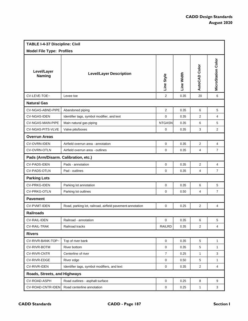
CADD Standards CADD - Page 187 Section I
CADD Design Standards
August 2020
TABLE I-4-37 Discipline: Civil
Model File Type: Profiles
Level/Layer
Naming
Level/Layer Description
Lin
e S
tyle
Lin
e W
idth
Au
toC
AD
Co
lor
Mic
roS
tati
on
Co
lor
CV-LEVE-TOE~ Levee toe 2 0.35 20 6
Natural Gas
CV-NGAS-ABND-PIPE Abandoned piping 2 0.35 6 5
CV-NGAS-IDEN Identifier tags, symbol modifier, and text 0 0.35 2 4
CV-NGAS-MAIN-PIPE Main natural gas piping NTGASN 0.35 6 5
CV-NGAS-PITS-VLVE Valve pits/boxes 0 0.35 3 2
Overrun Areas
CV-OVRN-IDEN Airfield overrun area - annotation 0 0.35 2 4
CV-OVRN-OTLN Airfield overrun area - outlines 0 0.35 4 7
Pads (Arm/Disarm. Calibration, etc.)
CV-PADS-IDEN Pads - annotation 0 0.35 2 4
CV-PADS-OTLN Pad - outlines 0 0.35 4 7
Parking Lots
CV-PRKG-IDEN Parking lot annotation 0 0.35 6 5
CV-PRKG-OTLN Parking lot outlines 0 0.50 4 7
Pavement
CV-PVMT-IDEN Road, parking lot, railroad, airfield pavement annotation 0 0.25 2 4
Railroads
CV-RAIL-IDEN Railroad - annotation 0 0.35 6 5
CV-RAIL-TRAK Railroad tracks RAILRD 0.35 2 4
Rivers
CV-RIVR-BANK-TOP~ Top of river bank 0 0.35 5 1
CV-RIVR-BOTM River bottom 0 0.35 5 1
CV-RIVR-CNTR Centerline of river 7 0.25 1 3
CV-RIVR-EDGE River edge 0 0.50 5 1
CV-RIVR-IDEN Identifier tags, symbol modifiers, and text 0 0.35 2 4
Roads, Streets, and Highways
CV-ROAD-ASPH Road outlines - asphalt surface 0 0.25 8 9
CV-ROAD-CNTR-IDEN Road centerline annotation 0 0.25 1 3
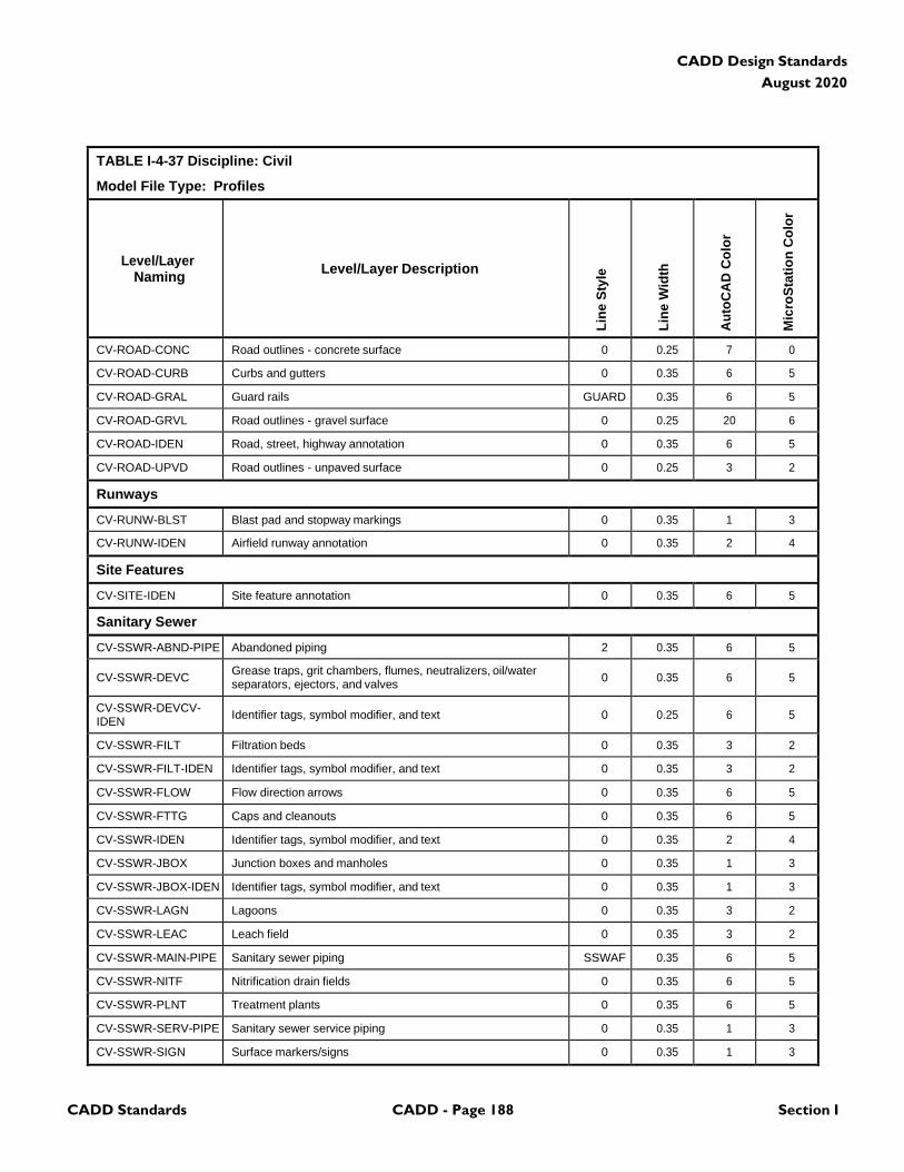
CADD Standards CADD - Page 188 Section I
CADD Design Standards
August 2020
TABLE I-4-37 Discipline: Civil
Model File Type: Profiles
Level/Layer
Naming
Level/Layer Description
Lin
e S
tyle
Lin
e W
idth
Au
toC
AD
Co
lor
Mic
roS
tati
on
Co
lor
CV-ROAD-CONC Road outlines - concrete surface 0 0.25 7 0
CV-ROAD-CURB Curbs and gutters 0 0.35 6 5
CV-ROAD-GRAL Guard rails GUARD 0.35 6 5
CV-ROAD-GRVL Road outlines - gravel surface 0 0.25 20 6
CV-ROAD-IDEN Road, street, highway annotation 0 0.35 6 5
CV-ROAD-UPVD Road outlines - unpaved surface 0 0.25 3 2
Runways
CV-RUNW-BLST Blast pad and stopway markings 0 0.35 1 3
CV-RUNW-IDEN Airfield runway annotation 0 0.35 2 4
Site Features
CV-SITE-IDEN Site feature annotation 0 0.35 6 5
Sanitary Sewer
CV-SSWR-ABND-PIPE Abandoned piping 2 0.35 6 5
CV-SSWR-DEVC Grease traps, grit chambers, flumes, neutralizers, oil/water separators, ejectors, and valves
0
0.35
6
5
CV-SSWR-DEVCV- IDEN
Identifier tags, symbol modifier, and text
0
0.25
6
5
CV-SSWR-FILT Filtration beds 0 0.35 3 2
CV-SSWR-FILT-IDEN Identifier tags, symbol modifier, and text 0 0.35 3 2
CV-SSWR-FLOW Flow direction arrows 0 0.35 6 5
CV-SSWR-FTTG Caps and cleanouts 0 0.35 6 5
CV-SSWR-IDEN Identifier tags, symbol modifier, and text 0 0.35 2 4
CV-SSWR-JBOX Junction boxes and manholes 0 0.35 1 3
CV-SSWR-JBOX-IDEN Identifier tags, symbol modifier, and text 0 0.35 1 3
CV-SSWR-LAGN Lagoons 0 0.35 3 2
CV-SSWR-LEAC Leach field 0 0.35 3 2
CV-SSWR-MAIN-PIPE Sanitary sewer piping SSWAF 0.35 6 5
CV-SSWR-NITF Nitrification drain fields 0 0.35 6 5
CV-SSWR-PLNT Treatment plants 0 0.35 6 5
CV-SSWR-SERV-PIPE Sanitary sewer service piping 0 0.35 1 3
CV-SSWR-SIGN Surface markers/signs 0 0.35 1 3
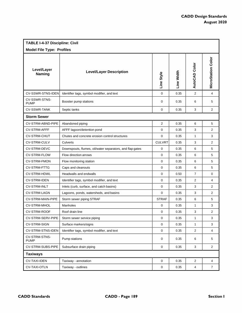
CADD Standards CADD - Page 189 Section I
CADD Design Standards
August 2020
TABLE I-4-37 Discipline: Civil
Model File Type: Profiles
Level/Layer
Naming
Level/Layer Description
Lin
e S
tyle
Lin
e W
idth
Au
toC
AD
Co
lor
Mic
roS
tati
on
Co
lor
CV-SSWR-STNS-IDEN Identifier tags, symbol modifier, and text 0 0.35 2 4
CV-SSWR-STNS- PUMP
Booster pump stations
0
0.35
6
5
CV-SSWR-TANK Septic tanks 0 0.35 3 2
Storm Sewer
CV-STRM-ABND-PIPE Abandoned piping 2 0.35 6 5
CV-STRM-AFFF AFFF lagoon/detention pond 0 0.35 3 2
CV-STRM-CHUT Chutes and concrete erosion control structures 0 0.35 1 3
CV-STRM-CULV Culverts CULVRT 0.35 3 2
CV-STRM-DEVC Downspouts, flumes, oil/water separators, and flap gates 0 0.35 6 5
CV-STRM-FLOW Flow direction arrows 0 0.35 6 5
CV-STRM-FMON Flow monitoring station 0 0.35 6 5
CV-STRM-FTTG Caps and cleanouts 0 0.35 6 5
CV-STRM-HDWL Headwalls and endwalls 0 0.50 7 0
CV-STRM-IDEN Identifier tags, symbol modifier, and text 0 0.35 2 4
CV-STRM-INLT Inlets (curb, surface, and catch basins) 0 0.35 3 2
CV-STRM-LAGN Lagoons, ponds, watersheds, and basins 0 0.35 3 2
CV-STRM-MAIN-PIPE Storm sewer piping STRAF STRAF 0.35 6 5
CV-STRM-MHOL Manholes 0 0.35 1 3
CV-STRM-ROOF Roof drain line 0 0.35 3 2
CV-STRM-SERV-PIPE Storm sewer service piping 0 0.35 1 3
CV-STRM-SIGN Surface markers/signs 0 0.35 1 3
CV-STRM-STNS-IDEN Identifier tags, symbol modifier, and text 0 0.35 2 4
CV-STRM-STNS- PUMP
Pump stations
0
0.35
6
5
CV-STRM-SUBS-PIPE Subsurface drain piping 0 0.35 3 2
Taxiways
CV-TAXI-IDEN Taxiway - annotation 0 0.35 2 4
CV-TAXI-OTLN Taxiway - outlines 0 0.35 4 7
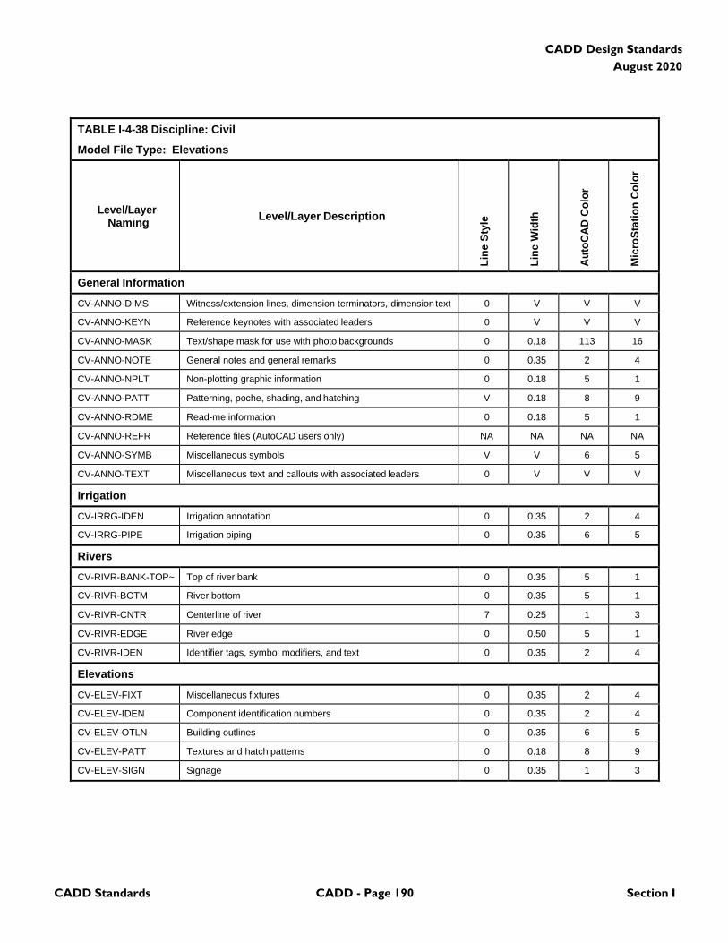
CADD Standards CADD - Page 190 Section I
CADD Design Standards
August 2020
TABLE I-4-38 Discipline: Civil
Model File Type: Elevations
Level/Layer
Naming
Level/Layer Description
Lin
e S
tyle
Lin
e W
idth
Au
toC
AD
Co
lor
Mic
roS
tati
on
Co
lor
General Information
CV-ANNO-DIMS Witness/extension lines, dimension terminators, dimension text 0 V V V
CV-ANNO-KEYN Reference keynotes with associated leaders 0 V V V
CV-ANNO-MASK Text/shape mask for use with photo backgrounds 0 0.18 113 16
CV-ANNO-NOTE General notes and general remarks 0 0.35 2 4
CV-ANNO-NPLT Non-plotting graphic information 0 0.18 5 1
CV-ANNO-PATT Patterning, poche, shading, and hatching V 0.18 8 9
CV-ANNO-RDME Read-me information 0 0.18 5 1
CV-ANNO-REFR Reference files (AutoCAD users only) NA NA NA NA
CV-ANNO-SYMB Miscellaneous symbols V V 6 5
CV-ANNO-TEXT Miscellaneous text and callouts with associated leaders 0 V V V
Irrigation
CV-IRRG-IDEN Irrigation annotation 0 0.35 2 4
CV-IRRG-PIPE Irrigation piping 0 0.35 6 5
Rivers
CV-RIVR-BANK-TOP~ Top of river bank 0 0.35 5 1
CV-RIVR-BOTM River bottom 0 0.35 5 1
CV-RIVR-CNTR Centerline of river 7 0.25 1 3
CV-RIVR-EDGE River edge 0 0.50 5 1
CV-RIVR-IDEN Identifier tags, symbol modifiers, and text 0 0.35 2 4
Elevations
CV-ELEV-FIXT Miscellaneous fixtures 0 0.35 2 4
CV-ELEV-IDEN Component identification numbers 0 0.35 2 4
CV-ELEV-OTLN Building outlines 0 0.35 6 5
CV-ELEV-PATT Textures and hatch patterns 0 0.18 8 9
CV-ELEV-SIGN Signage 0 0.35 1 3
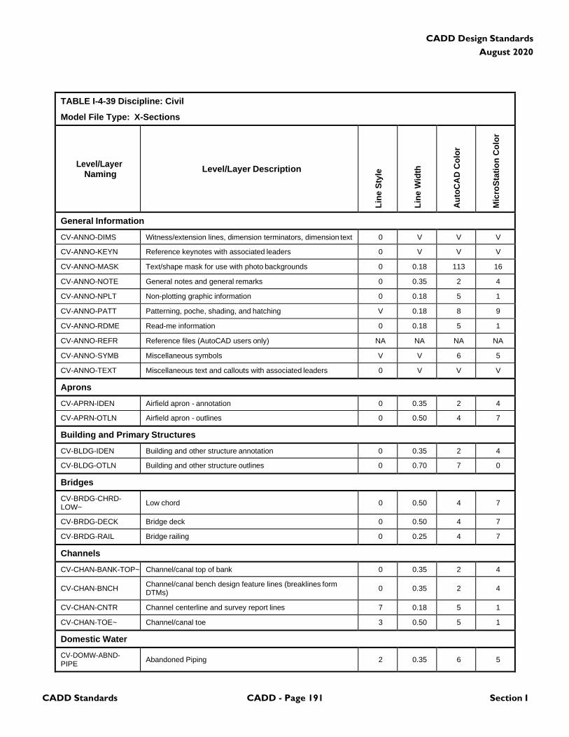
CADD Standards CADD - Page 191 Section I
CADD Design Standards
August 2020
TABLE I-4-39 Discipline: Civil
Model File Type: X-Sections
Level/Layer
Naming
Level/Layer Description
Lin
e S
tyle
Lin
e W
idth
Au
toC
AD
Co
lor
Mic
roS
tati
on
Co
lor
General Information
CV-ANNO-DIMS Witness/extension lines, dimension terminators, dimension text 0 V V V
CV-ANNO-KEYN Reference keynotes with associated leaders 0 V V V
CV-ANNO-MASK Text/shape mask for use with photo backgrounds 0 0.18 113 16
CV-ANNO-NOTE General notes and general remarks 0 0.35 2 4
CV-ANNO-NPLT Non-plotting graphic information 0 0.18 5 1
CV-ANNO-PATT Patterning, poche, shading, and hatching V 0.18 8 9
CV-ANNO-RDME Read-me information 0 0.18 5 1
CV-ANNO-REFR Reference files (AutoCAD users only) NA NA NA NA
CV-ANNO-SYMB Miscellaneous symbols V V 6 5
CV-ANNO-TEXT Miscellaneous text and callouts with associated leaders 0 V V V
Aprons
CV-APRN-IDEN Airfield apron - annotation 0 0.35 2 4
CV-APRN-OTLN Airfield apron - outlines 0 0.50 4 7
Building and Primary Structures
CV-BLDG-IDEN Building and other structure annotation 0 0.35 2 4
CV-BLDG-OTLN Building and other structure outlines 0 0.70 7 0
Bridges
CV-BRDG-CHRD- LOW~
Low chord
0
0.50
4
7
CV-BRDG-DECK Bridge deck 0 0.50 4 7
CV-BRDG-RAIL Bridge railing 0 0.25 4 7
Channels
CV-CHAN-BANK-TOP~ Channel/canal top of bank 0 0.35 2 4
CV-CHAN-BNCH Channel/canal bench design feature lines (breaklines form DTMs)
0
0.35
2
4
CV-CHAN-CNTR Channel centerline and survey report lines 7 0.18 5 1
CV-CHAN-TOE~ Channel/canal toe 3 0.50 5 1
Domestic Water
CV-DOMW-ABND- PIPE
Abandoned Piping
2
0.35
6
5
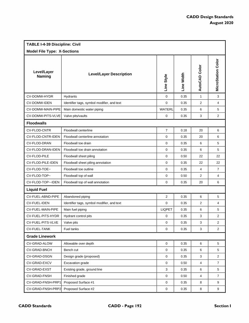
CADD Standards CADD - Page 192 Section I
CADD Design Standards
August 2020
TABLE I-4-39 Discipline: Civil
Model File Type: X-Sections
Level/Layer
Naming
Level/Layer Description
Lin
e S
tyle
Lin
e W
idth
Au
toC
AD
Co
lor
Mic
roS
tati
on
Co
lor
CV-DOMW-HYDR Hydrants 0 0.35 1 3
CV-DOMW-IDEN Identifier tags, symbol modifier, and text 0 0.35 2 4
CV-DOMW-MAIN-PIPE Main domestic water piping WATERL 0.35 6 5
CV-DOMW-PITS-VLVE Valve pits/vaults 0 0.35 3 2
Floodwalls
CV-FLOD-CNTR Floodwall centerline 7 0.18 20 6
CV-FLOD-CNTR-IDEN Floodwall centerline annotation 0 0.35 20 6
CV-FLOD-DRAN Floodwall toe drain 0 0.35 6 5
CV-FLOD-DRAN-IDEN Floodwall toe drain annotation 0 0.35 6 5
CV-FLOD-PILE Floodwall sheet piling 0 0.50 22 22
CV-FLOD-PILE-IDEN Floodwall sheet piling annotation 0 0.35 22 22
CV-FLOD-TOE~ Floodwall toe outline 0 0.35 4 7
CV-FLOD-TOP~ Floodwall top of wall 0 0.50 2 4
CV-FLOD-TOP~-IDEN Floodwall top of wall annotation 0 0.35 20 6
Liquid Fuel
CV-FUEL-ABND-PIPE Abandoned piping 2 0.35 6 5
CV-FUEL-IDEN Identifier tags, symbol modifier, and text 0 0.35 2 4
CV-FUEL-MAIN-PIPE Main fuel piping LIQPET 0.35 6 5
CV-FUEL-PITS-HYDR Hydrant control pits 0 0.35 3 2
CV-FUEL-PITS-VLVE Valve pits 0 0.35 3 2
CV-FUEL-TANK Fuel tanks 0 0.35 3 2
Grade Linework
CV-GRAD-ALOW Allowable over depth 0 0.35 6 5
CV-GRAD-BNCH Bench cut 0 0.35 6 5
CV-GRAD-DSGN Design grade (proposed) 0 0.35 3 2
CV-GRAD-EXCV Excavation grade 0 0.50 4 7
CV-GRAD-EXST Existing grade, ground line 3 0.35 6 5
CV-GRAD-FNSH Finished grade 0 0.50 4 7
CV-GRAD-FNSH-PRP1 Proposed Surface #1 0 0.35 8 9
CV-GRAD-FNSH-PRP2 Proposed Surface #2 0 0.35 8 9
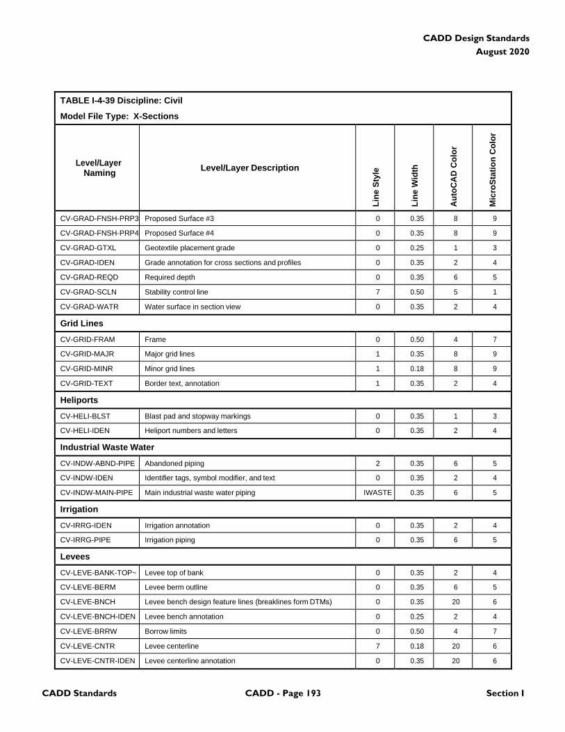
CADD Standards CADD - Page 193 Section I
CADD Design Standards
August 2020
TABLE I-4-39 Discipline: Civil
Model File Type: X-Sections
Level/Layer
Naming
Level/Layer Description
Lin
e S
tyle
Lin
e W
idth
Au
toC
AD
Co
lor
Mic
roS
tati
on
Co
lor
CV-GRAD-FNSH-PRP3 Proposed Surface #3 0 0.35 8 9
CV-GRAD-FNSH-PRP4 Proposed Surface #4 0 0.35 8 9
CV-GRAD-GTXL Geotextile placement grade 0 0.25 1 3
CV-GRAD-IDEN Grade annotation for cross sections and profiles 0 0.35 2 4
CV-GRAD-REQD Required depth 0 0.35 6 5
CV-GRAD-SCLN Stability control line 7 0.50 5 1
CV-GRAD-WATR Water surface in section view 0 0.35 2 4
Grid Lines
CV-GRID-FRAM Frame 0 0.50 4 7
CV-GRID-MAJR Major grid lines 1 0.35 8 9
CV-GRID-MINR Minor grid lines 1 0.18 8 9
CV-GRID-TEXT Border text, annotation 1 0.35 2 4
Heliports
CV-HELI-BLST Blast pad and stopway markings 0 0.35 1 3
CV-HELI-IDEN Heliport numbers and letters 0 0.35 2 4
Industrial Waste Water
CV-INDW-ABND-PIPE Abandoned piping 2 0.35 6 5
CV-INDW-IDEN Identifier tags, symbol modifier, and text 0 0.35 2 4
CV-INDW-MAIN-PIPE Main industrial waste water piping IWASTE 0.35 6 5
Irrigation
CV-IRRG-IDEN Irrigation annotation 0 0.35 2 4
CV-IRRG-PIPE Irrigation piping 0 0.35 6 5
Levees
CV-LEVE-BANK-TOP~ Levee top of bank 0 0.35 2 4
CV-LEVE-BERM Levee berm outline 0 0.35 6 5
CV-LEVE-BNCH Levee bench design feature lines (breaklines form DTMs) 0 0.35 20 6
CV-LEVE-BNCH-IDEN Levee bench annotation 0 0.25 2 4
CV-LEVE-BRRW Borrow limits 0 0.50 4 7
CV-LEVE-CNTR Levee centerline 7 0.18 20 6
CV-LEVE-CNTR-IDEN Levee centerline annotation 0 0.35 20 6
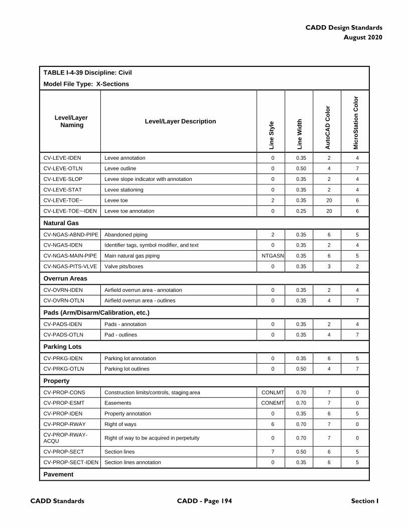
CADD Standards CADD - Page 194 Section I
CADD Design Standards
August 2020
TABLE I-4-39 Discipline: Civil
Model File Type: X-Sections
Level/Layer
Naming
Level/Layer Description
Lin
e S
tyle
Lin
e W
idth
Au
toC
AD
Co
lor
Mic
roS
tati
on
Co
lor
CV-LEVE-IDEN Levee annotation 0 0.35 2 4
CV-LEVE-OTLN Levee outline 0 0.50 4 7
CV-LEVE-SLOP Levee slope indicator with annotation 0 0.35 2 4
CV-LEVE-STAT Levee stationing 0 0.35 2 4
CV-LEVE-TOE~ Levee toe 2 0.35 20 6
CV-LEVE-TOE~-IDEN Levee toe annotation 0 0.25 20 6
Natural Gas
CV-NGAS-ABND-PIPE Abandoned piping 2 0.35 6 5
CV-NGAS-IDEN Identifier tags, symbol modifier, and text 0 0.35 2 4
CV-NGAS-MAIN-PIPE Main natural gas piping NTGASN 0.35 6 5
CV-NGAS-PITS-VLVE Valve pits/boxes 0 0.35 3 2
Overrun Areas
CV-OVRN-IDEN Airfield overrun area - annotation 0 0.35 2 4
CV-OVRN-OTLN Airfield overrun area - outlines 0 0.35 4 7
Pads (Arm/Disarm/Calibration, etc.)
CV-PADS-IDEN Pads - annotation 0 0.35 2 4
CV-PADS-OTLN Pad - outlines 0 0.35 4 7
Parking Lots
CV-PRKG-IDEN Parking lot annotation 0 0.35 6 5
CV-PRKG-OTLN Parking lot outlines 0 0.50 4 7
Property
CV-PROP-CONS Construction limits/controls, staging area CONLMT 0.70 7 0
CV-PROP-ESMT Easements CONEMT 0.70 7 0
CV-PROP-IDEN Property annotation 0 0.35 6 5
CV-PROP-RWAY Right of ways 6 0.70 7 0
CV-PROP-RWAY- ACQU
Right of way to be acquired in perpetuity
0
0.70
7
0
CV-PROP-SECT Section lines 7 0.50 6 5
CV-PROP-SECT-IDEN Section lines annotation 0 0.35 6 5
Pavement
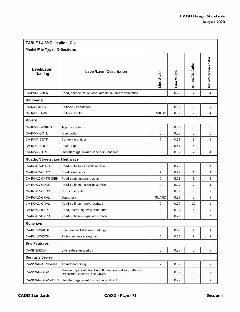
CADD Standards CADD - Page 195 Section I
CADD Design Standards
August 2020
TABLE I-4-39 Discipline: Civil
Model File Type: X-Sections
Level/Layer
Naming
Level/Layer Description
Lin
e S
tyle
Lin
e W
idth
Au
toC
AD
Co
lor
Mic
roS
tati
on
Co
lor
CV-PVMT-IDEN Road, parking lot, railroad, airfield pavement annotation 0 0.25 2 4
Railroads
CV-RAIL-IDEN Railroad - annotation 0 0.35 6 5
CV-RAIL-TRAK Railroad tracks RAILRD 0.35 2 4
Rivers
CV-RIVR-BANK-TOP~ Top of river bank 0 0.35 5 1
CV-RIVR-BOTM River bottom 0 0.35 5 1
CV-RIVR-CNTR Centerline of river 7 0.25 1 3
CV-RIVR-EDGE River edge 0 0.50 5 1
CV-RIVR-IDEN Identifier tags, symbol modifiers, and text 0 0.35 2 4
Roads, Streets, and Highways
CV-ROAD-ASPH Road outlines - asphalt surface 0 0.25 8 9
CV-ROAD-CNTR Road centerlines 7 0.25 1 3
CV-ROAD-CNTR-IDEN Road centerline annotation 0 0.25 1 3
CV-ROAD-CONC Road outlines - concrete surface 0 0.25 7 0
CV-ROAD-CURB Curbs and gutters 0 0.35 6 5
CV-ROAD-GRAL Guard rails GUARD 0.35 6 5
CV-ROAD-GRVL Road outlines - gravel surface 0 0.25 20 6
CV-ROAD-IDEN Road, street, highway annotation 0 0.35 6 5
CV-ROAD-UPVD Road outlines - unpaved surface 0 0.25 3 2
Runways
CV-RUNW-BLST Blast pad and stopway markings 0 0.35 1 3
CV-RUNW-IDEN Airfield runway annotation 0 0.35 2 4
Site Features
CV-SITE-IDEN Site feature annotation 0 0.35 6 5
Sanitary Sewer
CV-SSWR-ABND-PIPE Abandoned piping 2 0.35 6 5
CV-SSWR-DEVC Grease traps, grit chambers, flumes, neutralizers, oil/water separators, ejectors, and valves
0
0.35
6
5
CV-SSWR-DEVC-IDEN Identifier tags, symbol modifier, and text 0 0.25 6 5
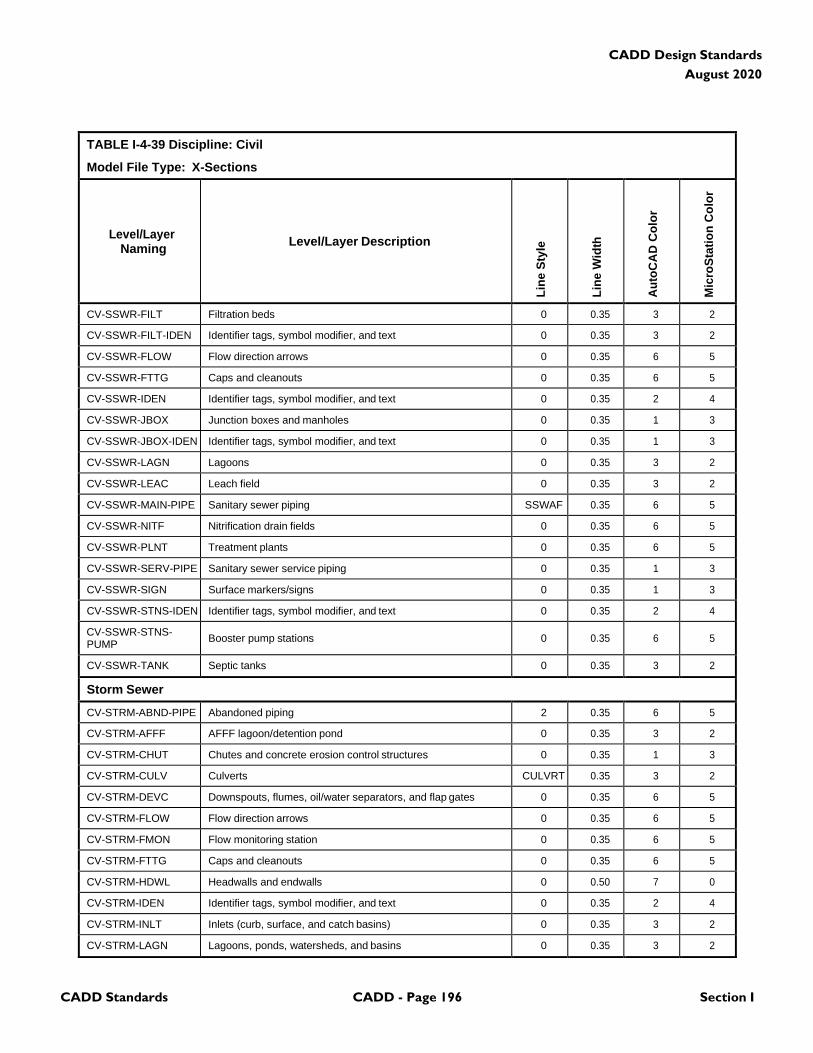
CADD Standards CADD - Page 196 Section I
CADD Design Standards
August 2020
TABLE I-4-39 Discipline: Civil
Model File Type: X-Sections
Level/Layer
Naming
Level/Layer Description
Lin
e S
tyle
Lin
e W
idth
Au
toC
AD
Co
lor
Mic
roS
tati
on
Co
lor
CV-SSWR-FILT Filtration beds 0 0.35 3 2
CV-SSWR-FILT-IDEN Identifier tags, symbol modifier, and text 0 0.35 3 2
CV-SSWR-FLOW Flow direction arrows 0 0.35 6 5
CV-SSWR-FTTG Caps and cleanouts 0 0.35 6 5
CV-SSWR-IDEN Identifier tags, symbol modifier, and text 0 0.35 2 4
CV-SSWR-JBOX Junction boxes and manholes 0 0.35 1 3
CV-SSWR-JBOX-IDEN Identifier tags, symbol modifier, and text 0 0.35 1 3
CV-SSWR-LAGN Lagoons 0 0.35 3 2
CV-SSWR-LEAC Leach field 0 0.35 3 2
CV-SSWR-MAIN-PIPE Sanitary sewer piping SSWAF 0.35 6 5
CV-SSWR-NITF Nitrification drain fields 0 0.35 6 5
CV-SSWR-PLNT Treatment plants 0 0.35 6 5
CV-SSWR-SERV-PIPE Sanitary sewer service piping 0 0.35 1 3
CV-SSWR-SIGN Surface markers/signs 0 0.35 1 3
CV-SSWR-STNS-IDEN Identifier tags, symbol modifier, and text 0 0.35 2 4
CV-SSWR-STNS- PUMP
Booster pump stations
0
0.35
6
5
CV-SSWR-TANK Septic tanks 0 0.35 3 2
Storm Sewer
CV-STRM-ABND-PIPE Abandoned piping 2 0.35 6 5
CV-STRM-AFFF AFFF lagoon/detention pond 0 0.35 3 2
CV-STRM-CHUT Chutes and concrete erosion control structures 0 0.35 1 3
CV-STRM-CULV Culverts CULVRT 0.35 3 2
CV-STRM-DEVC Downspouts, flumes, oil/water separators, and flap gates 0 0.35 6 5
CV-STRM-FLOW Flow direction arrows 0 0.35 6 5
CV-STRM-FMON Flow monitoring station 0 0.35 6 5
CV-STRM-FTTG Caps and cleanouts 0 0.35 6 5
CV-STRM-HDWL Headwalls and endwalls 0 0.50 7 0
CV-STRM-IDEN Identifier tags, symbol modifier, and text 0 0.35 2 4
CV-STRM-INLT Inlets (curb, surface, and catch basins) 0 0.35 3 2
CV-STRM-LAGN Lagoons, ponds, watersheds, and basins 0 0.35 3 2
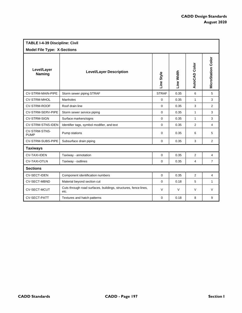
CADD Standards CADD - Page 197 Section I
CADD Design Standards
August 2020
TABLE I-4-39 Discipline: Civil
Model File Type: X-Sections
Level/Layer
Naming
Level/Layer Description
Lin
e S
tyle
Lin
e W
idth
Au
toC
AD
Co
lor
Mic
roS
tati
on
Co
lor
CV-STRM-MAIN-PIPE Storm sewer piping STRAF STRAF 0.35 6 5
CV-STRM-MHOL Manholes 0 0.35 1 3
CV-STRM-ROOF Roof drain line 0 0.35 3 2
CV-STRM-SERV-PIPE Storm sewer service piping 0 0.35 1 3
CV-STRM-SIGN Surface markers/signs 0 0.35 1 3
CV-STRM-STNS-IDEN Identifier tags, symbol modifier, and text 0 0.35 2 4
CV-STRM-STNS- PUMP
Pump stations
0
0.35
6
5
CV-STRM-SUBS-PIPE Subsurface drain piping 0 0.35 3 2
Taxiways
CV-TAXI-IDEN Taxiway - annotation 0 0.35 2 4
CV-TAXI-OTLN Taxiway - outlines 0 0.35 4 7
Sections
CV-SECT-IDEN Component identification numbers 0 0.35 2 4
CV-SECT-MBND Material beyond section cut 0 0.18 5 1
CV-SECT-MCUT Cuts through road surfaces, buildings, structures, fence lines, etc.
V
V
V
V
CV-SECT-PATT Textures and hatch patterns 0 0.18 8 9
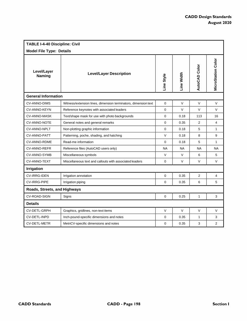
CADD Standards CADD - Page 198 Section I
CADD Design Standards
August 2020
TABLE I-4-40 Discipline: Civil
Model File Type: Details
Level/Layer
Naming
Level/Layer Description
Lin
e S
tyle
Lin
e W
idth
Au
toC
AD
Co
lor
Mic
roS
tati
on
Co
lor
General Information
CV-ANNO-DIMS Witness/extension lines, dimension terminators, dimension text 0 V V V
CV-ANNO-KEYN Reference keynotes with associated leaders 0 V V V
CV-ANNO-MASK Text/shape mask for use with photo backgrounds 0 0.18 113 16
CV-ANNO-NOTE General notes and general remarks 0 0.35 2 4
CV-ANNO-NPLT Non-plotting graphic information 0 0.18 5 1
CV-ANNO-PATT Patterning, poche, shading, and hatching V 0.18 8 9
CV-ANNO-RDME Read-me information 0 0.18 5 1
CV-ANNO-REFR Reference files (AutoCAD users only) NA NA NA NA
CV-ANNO-SYMB Miscellaneous symbols V V 6 5
CV-ANNO-TEXT Miscellaneous text and callouts with associated leaders 0 V V V
Irrigation
CV-IRRG-IDEN Irrigation annotation 0 0.35 2 4
CV-IRRG-PIPE Irrigation piping 0 0.35 6 5
Roads, Streets, and Highways
CV-ROAD-SIGN Signs 0 0.25 1 3
Details
CV-DETL-GRPH Graphics, gridlines, non-text items V V V V
CV-DETL-INPD Inch-pound-specific dimensions and notes 0 0.35 1 3
CV-DETL-METR MetriCV-specific dimensions and notes 0 0.35 3 2

CADD Standards CADD - Page 199 Section I
CADD Design Standards
August 2020
4.9 Landscape
TABLE I-4-41 Discipline: Landscape
Model File Type: Demolition Plan
Level/Layer
Naming
Level/Layer Description
Lin
e S
tyle
Lin
e W
idth
Au
toC
AD
Co
lor
Mic
roS
tati
on
Co
lor
General Information
LA-ANNO-DIMS Witness extension lines, dimensions arrowheads and text 0 V V V
LA-ANNO-KEYN Keynote with associated leaderlines and arrowheads 0 V V V
LA-ANNO-NPLT Construction lines, reference targets, area calculations V 0 5 1
LA-ANNO-PATT Miscellaneous patterning 0 0 8 9
LA-ANNO-NOTE General note and general remarks 0 2 2 4
LA-ANNO-SYMB Reference bubbles, matchlines, breaklines V 2 6 5
LA-ANNO-TEXT Detail title text, leaderlines, arrowheads, notes 0 V V V
LA-STAT-DEMO Demolition 2 2 6 5
LA-STAT-EXST Existing to remain 0 1 3 2
LA-STAT-MOVE Items to be moved 5 2 6 5
LA-STAT-NICN Not in contract 3 0 8 9
LA-STAT-PHS# Phase numbers (# = 1-9) 0 2 2 4
LA-STAT-RELO Relocated items 2 0 5 1
LA-STAT-TEMP Temporary work 4 3 4 7
LA-DEMO-HAZW Hazardous waste 0 2 6 5
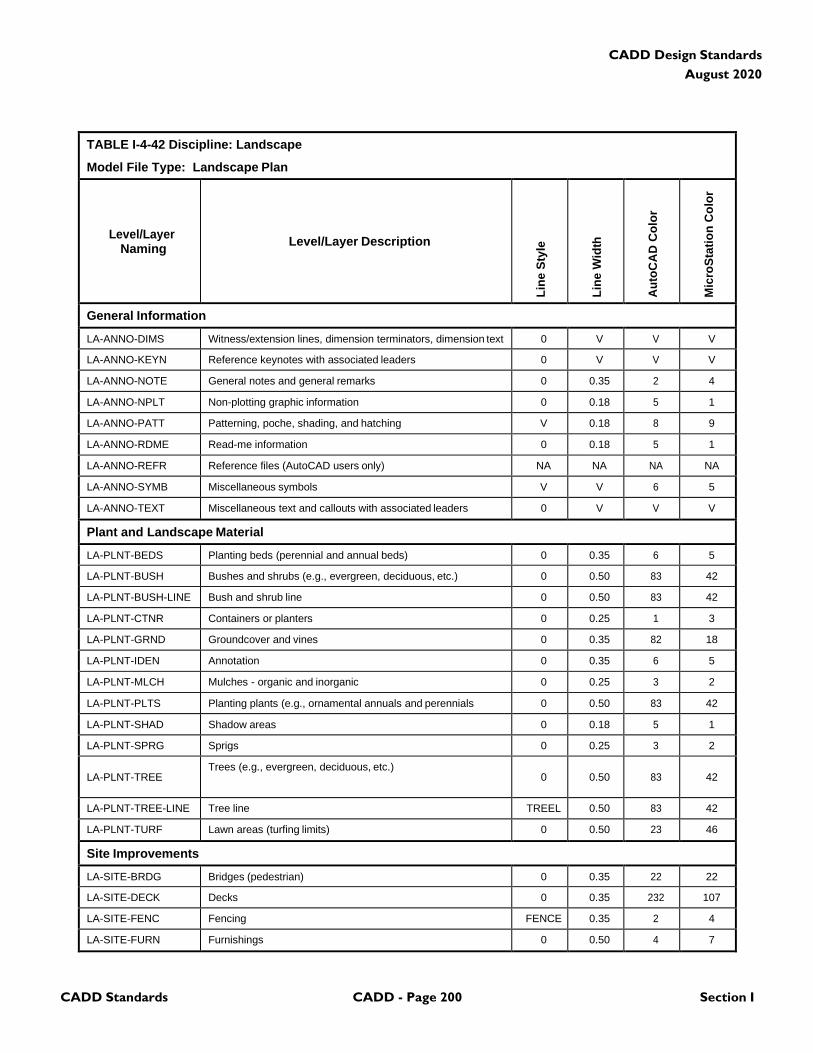
CADD Standards CADD - Page 200 Section I
CADD Design Standards
August 2020
TABLE I-4-42 Discipline: Landscape
Model File Type: Landscape Plan
Level/Layer
Naming
Level/Layer Description
Lin
e S
tyle
Lin
e W
idth
Au
toC
AD
Co
lor
Mic
roS
tati
on
Co
lor
General Information
LA-ANNO-DIMS Witness/extension lines, dimension terminators, dimension text 0 V V V
LA-ANNO-KEYN Reference keynotes with associated leaders 0 V V V
LA-ANNO-NOTE General notes and general remarks 0 0.35 2 4
LA-ANNO-NPLT Non-plotting graphic information 0 0.18 5 1
LA-ANNO-PATT Patterning, poche, shading, and hatching V 0.18 8 9
LA-ANNO-RDME Read-me information 0 0.18 5 1
LA-ANNO-REFR Reference files (AutoCAD users only) NA NA NA NA
LA-ANNO-SYMB Miscellaneous symbols V V 6 5
LA-ANNO-TEXT Miscellaneous text and callouts with associated leaders 0 V V V
Plant and Landscape Material
LA-PLNT-BEDS Planting beds (perennial and annual beds) 0 0.35 6 5
LA-PLNT-BUSH Bushes and shrubs (e.g., evergreen, deciduous, etc.) 0 0.50 83 42
LA-PLNT-BUSH-LINE Bush and shrub line 0 0.50 83 42
LA-PLNT-CTNR Containers or planters 0 0.25 1 3
LA-PLNT-GRND Groundcover and vines 0 0.35 82 18
LA-PLNT-IDEN Annotation 0 0.35 6 5
LA-PLNT-MLCH Mulches - organic and inorganic 0 0.25 3 2
LA-PLNT-PLTS Planting plants (e.g., ornamental annuals and perennials 0 0.50 83 42
LA-PLNT-SHAD Shadow areas 0 0.18 5 1
LA-PLNT-SPRG Sprigs 0 0.25 3 2
LA-PLNT-TREE
Trees (e.g., evergreen, deciduous, etc.) 0
0.50
83
42
LA-PLNT-TREE-LINE Tree line TREEL 0.50 83 42
LA-PLNT-TURF Lawn areas (turfing limits) 0 0.50 23 46
Site Improvements
LA-SITE-BRDG Bridges (pedestrian) 0 0.35 22 22
LA-SITE-DECK Decks 0 0.35 232 107
LA-SITE-FENC Fencing FENCE 0.35 2 4
LA-SITE-FURN Furnishings 0 0.50 4 7
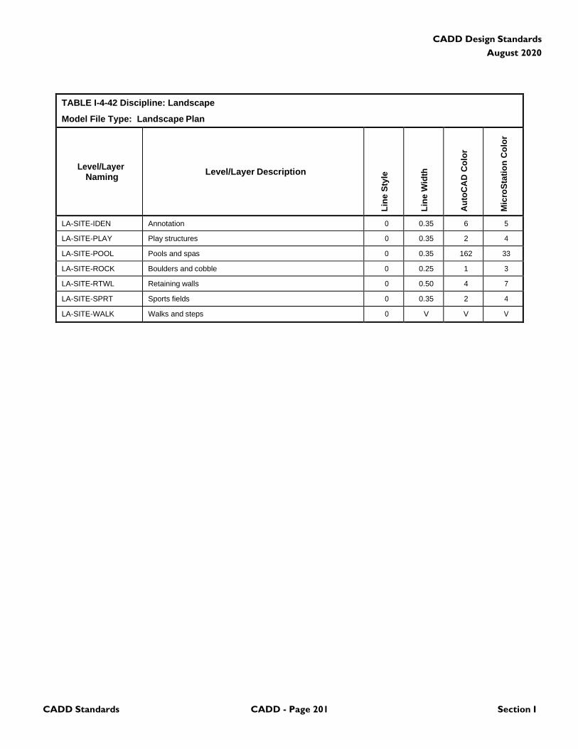
CADD Standards CADD - Page 201 Section I
CADD Design Standards
August 2020
TABLE I-4-42 Discipline: Landscape
Model File Type: Landscape Plan
Level/Layer
Naming
Level/Layer Description
Lin
e S
tyle
Lin
e W
idth
Au
toC
AD
Co
lor
Mic
roS
tati
on
Co
lor
LA-SITE-IDEN Annotation 0 0.35 6 5
LA-SITE-PLAY Play structures 0 0.35 2 4
LA-SITE-POOL Pools and spas 0 0.35 162 33
LA-SITE-ROCK Boulders and cobble 0 0.25 1 3
LA-SITE-RTWL Retaining walls 0 0.50 4 7
LA-SITE-SPRT Sports fields 0 0.35 2 4
LA-SITE-WALK Walks and steps 0 V V V
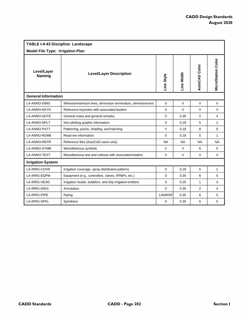
CADD Standards CADD - Page 202 Section I
CADD Design Standards
August 2020
TABLE I-4-43 Discipline: Landscape
Model File Type: Irrigation Plan
Level/Layer
Naming
Level/Layer Description
Lin
e S
tyle
Lin
e W
idth
Au
toC
AD
Co
lor
Mic
roS
tati
on
Co
lor
General Information
LA-ANNO-DIMS Witness/extension lines, dimension terminators, dimension text 0 V V V
LA-ANNO-KEYN Reference keynotes with associated leaders 0 V V V
LA-ANNO-NOTE General notes and general remarks 0 0.35 2 4
LA-ANNO-NPLT Non-plotting graphic information 0 0.18 5 1
LA-ANNO-PATT Patterning, poche, shading, and hatching V 0.18 8 9
LA-ANNO-RDME Read-me information 0 0.18 5 1
LA-ANNO-REFR Reference files (AutoCAD users only) NA NA NA NA
LA-ANNO-SYMB Miscellaneous symbols V V 6 5
LA-ANNO-TEXT Miscellaneous text and callouts with associated leaders 0 V V V
Irrigation System
LA-IRRG-COVR Irrigation coverage, spray distribution patterns 0 0.18 5 1
LA-IRRG-EQPM Equipment (e.g., controllers, valves, RPBPs, etc.) 0 0.35 6 5
LA-IRRG-HEAD Irrigation heads, bubblers, and drip irrigation emitters 0 0.25 1 3
LA-IRRG-IDEN Annotation 0 0.35 2 4
LA-IRRG-PIPE Piping LAWNSP 0.35 6 5
LA-IRRG-SPKL Sprinklers 0 0.35 6 5
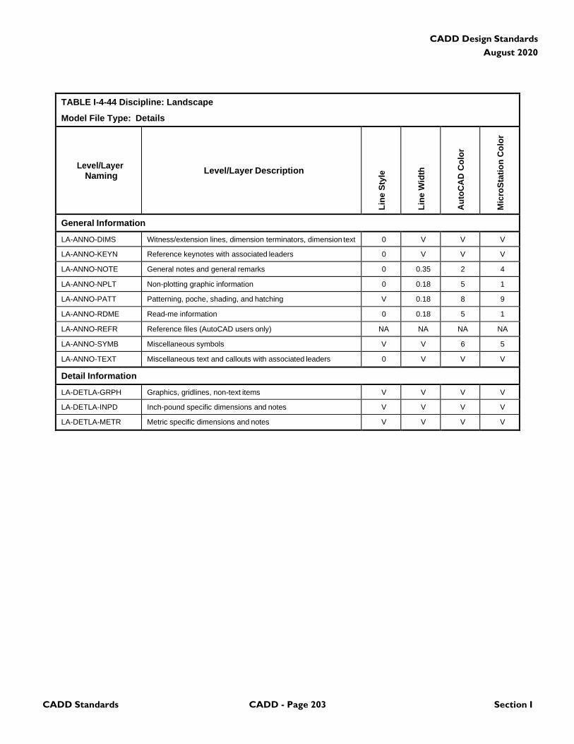
CADD Standards CADD - Page 203 Section I
CADD Design Standards
August 2020
TABLE I-4-44 Discipline: Landscape
Model File Type: Details
Level/Layer
Naming
Level/Layer Description
Lin
e S
tyle
Lin
e W
idth
Au
toC
AD
Co
lor
Mic
roS
tati
on
Co
lor
General Information
LA-ANNO-DIMS Witness/extension lines, dimension terminators, dimension text 0 V V V
LA-ANNO-KEYN Reference keynotes with associated leaders 0 V V V
LA-ANNO-NOTE General notes and general remarks 0 0.35 2 4
LA-ANNO-NPLT Non-plotting graphic information 0 0.18 5 1
LA-ANNO-PATT Patterning, poche, shading, and hatching V 0.18 8 9
LA-ANNO-RDME Read-me information 0 0.18 5 1
LA-ANNO-REFR Reference files (AutoCAD users only) NA NA NA NA
LA-ANNO-SYMB Miscellaneous symbols V V 6 5
LA-ANNO-TEXT Miscellaneous text and callouts with associated leaders 0 V V V
Detail Information
LA-DETLA-GRPH Graphics, gridlines, non-text items V V V V
LA-DETLA-INPD Inch-pound specific dimensions and notes V V V V
LA-DETLA-METR Metric specific dimensions and notes V V V V

CADD Standards CADD - Page 204 Section I
CADD Design Standards
August 2020
4.10 Structural Buildings
TABLE I-4-45 Discipline: Structural Buildings
Model File Type: Demolition Plan
Level/Layer
Naming
Level/Layer Description
Lin
e S
tyle
Lin
e W
idth
Au
toC
AD
Co
lor
Mic
roS
tati
on
Co
lor
General Information
ST-ANNO-DIMS Witness extension lines, dimensions arrowheads and text 0 V V V
ST-ANNO-KEYN Keynote with associated leaderlines and arrowheads 0 V V V
ST-ANNO-NPLT Construction lines, reference targets, area calculations V 0 5 1
ST-ANNO-PATT Miscellaneous patterning 0 0 8 9
ST-ANNO-NOTE General note and general remarks 0 2 2 4
ST-ANNO-SYMB Reference bubbles, matchlines, breaklines V 2 6 5
ST-ANNO-TEXT Detail title text, leaderlines, arrowheads, notes 0 V V V
ST-STAT-DEMO Demolition 2 2 6 5
ST-STAT-EXST Existing to remain 0 1 3 2
ST-STAT-MOVE Items to be moved 5 2 6 5
ST-STAT-NICN Not in contract 3 0 8 9
ST-STAT-PHS# Phase numbers (# = 1-9) 0 2 2 4
ST-STAT-RELO Relocated items 2 0 5 1
ST-STAT-TEMP Temporary work 4 3 4 7
ST-DEMO-HAZW Hazardous waste
0 2 6 5
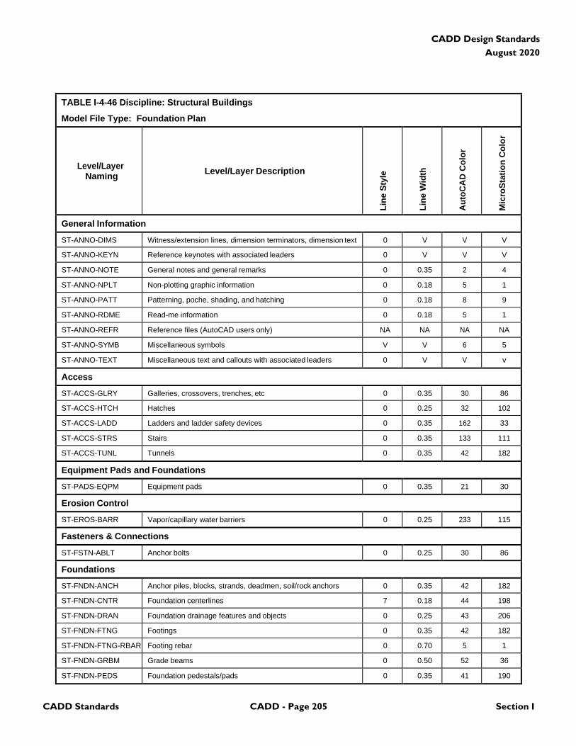
CADD Standards CADD - Page 205 Section I
CADD Design Standards
August 2020
TABLE I-4-46 Discipline: Structural Buildings
Model File Type: Foundation Plan
Level/Layer
Naming
Level/Layer Description
Lin
e S
tyle
Lin
e W
idth
Au
toC
AD
Co
lor
Mic
roS
tati
on
Co
lor
General Information
ST-ANNO-DIMS Witness/extension lines, dimension terminators, dimension text 0 V V V
ST-ANNO-KEYN Reference keynotes with associated leaders 0 V V V
ST-ANNO-NOTE General notes and general remarks 0 0.35 2 4
ST-ANNO-NPLT Non-plotting graphic information 0 0.18 5 1
ST-ANNO-PATT Patterning, poche, shading, and hatching 0 0.18 8 9
ST-ANNO-RDME Read-me information 0 0.18 5 1
ST-ANNO-REFR Reference files (AutoCAD users only) NA NA NA NA
ST-ANNO-SYMB Miscellaneous symbols V V 6 5
ST-ANNO-TEXT Miscellaneous text and callouts with associated leaders 0 V V v
Access
ST-ACCS-GLRY Galleries, crossovers, trenches, etc 0 0.35 30 86
ST-ACCS-HTCH Hatches 0 0.25 32 102
ST-ACCS-LADD Ladders and ladder safety devices 0 0.35 162 33
ST-ACCS-STRS Stairs 0 0.35 133 111
ST-ACCS-TUNL Tunnels 0 0.35 42 182
Equipment Pads and Foundations
ST-PADS-EQPM Equipment pads 0 0.35 21 30
Erosion Control
ST-EROS-BARR Vapor/capillary water barriers 0 0.25 233 115
Fasteners & Connections
ST-FSTN-ABLT Anchor bolts 0 0.25 30 86
Foundations
ST-FNDN-ANCH Anchor piles, blocks, strands, deadmen, soil/rock anchors 0 0.35 42 182
ST-FNDN-CNTR Foundation centerlines 7 0.18 44 198
ST-FNDN-DRAN Foundation drainage features and objects 0 0.25 43 206
ST-FNDN-FTNG Footings 0 0.35 42 182
ST-FNDN-FTNG-RBAR Footing rebar 0 0.70 5 1
ST-FNDN-GRBM Grade beams 0 0.50 52 36
ST-FNDN-PEDS Foundation pedestals/pads 0 0.35 41 190
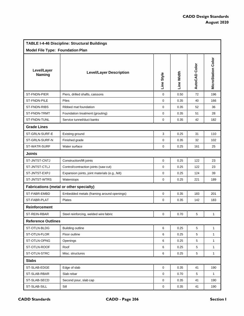
CADD Standards CADD - Page 206 Section I
CADD Design Standards
August 2020
TABLE I-4-46 Discipline: Structural Buildings
Model File Type: Foundation Plan
Level/Layer
Naming
Level/Layer Description
Lin
e S
tyle
Lin
e W
idth
Au
toC
AD
Co
lor
Mic
roS
tati
on
Co
lor
ST-FNDN-PIER Piers, drilled shafts, caissons 0 0.50 72 196
ST-FNDN-PILE Piles 0 0.35 40 166
ST-FNDN-RIBS Ribbed mat foundation 0 0.35 52 36
ST-FNDN-TRMT Foundation treatment (grouting) 0 0.35 51 28
ST-FNDN-TUNL Service tunnel/duct banks 0 0.35 42 182
Grade Lines
ST-GRLN-SURF-E Existing ground 3 0.25 31 110
ST-GRLN-SURF-N Finished grade 0 0.35 32 102
ST-WATR-SURF Water surface 0 0.25 161 25
Joints
ST-JNTST-CNTJ Construction/lift joints 0 0.25 122 23
ST-JNTST-CTLJ Control/contraction joints (saw cut) 0 0.25 122 23
ST-JNTST-EXPJ Expansion joints, joint materials (e.g., felt) 0 0.25 124 39
ST-JNTST-WTRS Waterstops 0 0.25 221 189
Fabrications (metal or other specialty)
ST-FABR-EMBD Embedded metals (framing around openings) 0 0.35 183 201
ST-FABR-PLAT Plates 0 0.35 142 183
Reinforcement
ST-REIN-RBAR Steel reinforcing, welded wire fabric 0 0.70 5 1
Reference Outlines
ST-OTLN-BLDG Building outline 6 0.25 5 1
ST-OTLN-FLOR Floor outline 6 0.25 5 1
ST-OTLN-OPNG Openings 6 0.25 5 1
ST-OTLN-ROOF Roof 6 0.25 5 1
ST-OTLN-STRC Misc. structures 6 0.25 5 1
Slabs
ST-SLAB-EDGE Edge of slab 0 0.35 41 190
ST-SLAB-RBAR Slab rebar 0 0.70 5 1
ST-SLAB-SECD Second pour, slab cap 0 0.35 41 190
ST-SLAB-SILL Sill 0 0.35 41 190
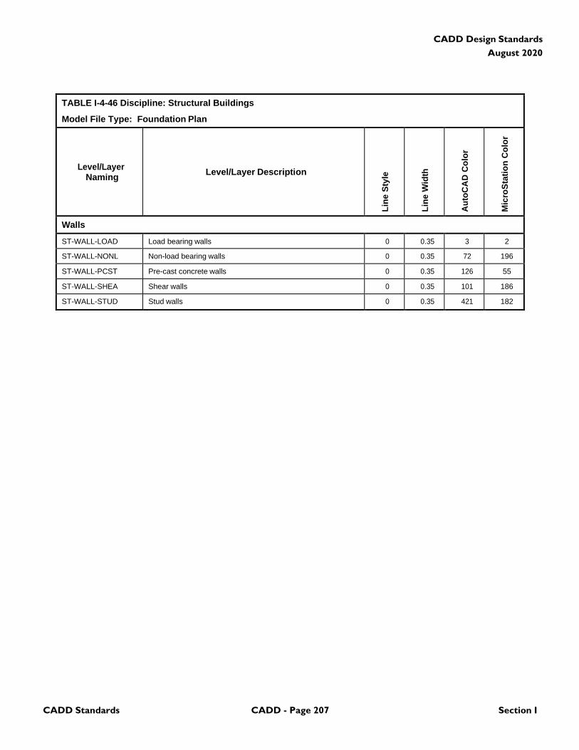
CADD Standards CADD - Page 207 Section I
CADD Design Standards
August 2020
TABLE I-4-46 Discipline: Structural Buildings
Model File Type: Foundation Plan
Level/Layer
Naming
Level/Layer Description
Lin
e S
tyle
Lin
e W
idth
Au
toC
AD
Co
lor
Mic
roS
tati
on
Co
lor
Walls
ST-WALL-LOAD Load bearing walls 0 0.35 3 2
ST-WALL-NONL Non-load bearing walls 0 0.35 72 196
ST-WALL-PCST Pre-cast concrete walls 0 0.35 126 55
ST-WALL-SHEA Shear walls 0 0.35 101 186
ST-WALL-STUD Stud walls 0 0.35 421 182
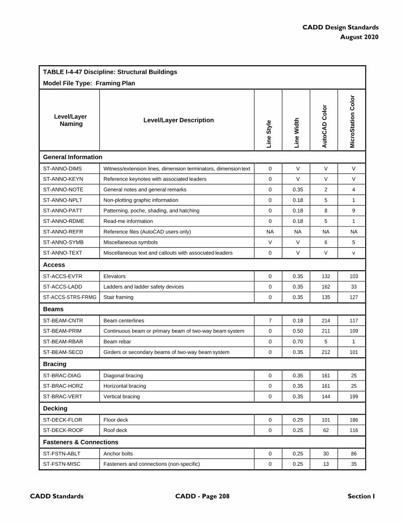
CADD Standards CADD - Page 208 Section I
CADD Design Standards
August 2020
TABLE I-4-47 Discipline: Structural Buildings
Model File Type: Framing Plan
Level/Layer
Naming
Level/Layer Description
Lin
e S
tyle
Lin
e W
idth
Au
toC
AD
Co
lor
Mic
roS
tati
on
Co
lor
General Information
ST-ANNO-DIMS Witness/extension lines, dimension terminators, dimension text 0 V V V
ST-ANNO-KEYN Reference keynotes with associated leaders 0 V V V
ST-ANNO-NOTE General notes and general remarks 0 0.35 2 4
ST-ANNO-NPLT Non-plotting graphic information 0 0.18 5 1
ST-ANNO-PATT Patterning, poche, shading, and hatching 0 0.18 8 9
ST-ANNO-RDME Read-me information 0 0.18 5 1
ST-ANNO-REFR Reference files (AutoCAD users only) NA NA NA NA
ST-ANNO-SYMB Miscellaneous symbols V V 6 5
ST-ANNO-TEXT Miscellaneous text and callouts with associated leaders 0 V V v
Access
ST-ACCS-EVTR Elevators 0 0.35 132 103
ST-ACCS-LADD Ladders and ladder safety devices 0 0.35 162 33
ST-ACCS-STRS-FRMG Stair framing 0 0.35 135 127
Beams
ST-BEAM-CNTR Beam centerlines 7 0.18 214 117
ST-BEAM-PRIM Continuous beam or primary beam of two-way beam system 0 0.50 211 109
ST-BEAM-RBAR Beam rebar 0 0.70 5 1
ST-BEAM-SECD Girders or secondary beams of two-way beam system 0 0.35 212 101
Bracing
ST-BRAC-DIAG Diagonal bracing 0 0.35 161 25
ST-BRAC-HORZ Horizontal bracing 0 0.35 161 25
ST-BRAC-VERT Vertical bracing 0 0.35 144 199
Decking
ST-DECK-FLOR Floor deck 0 0.25 101 186
ST-DECK-ROOF Roof deck 0 0.25 62 116
Fasteners & Connections
ST-FSTN-ABLT Anchor bolts 0 0.25 30 86
ST-FSTN-MISC Fasteners and connections (non-specific) 0 0.25 13 35
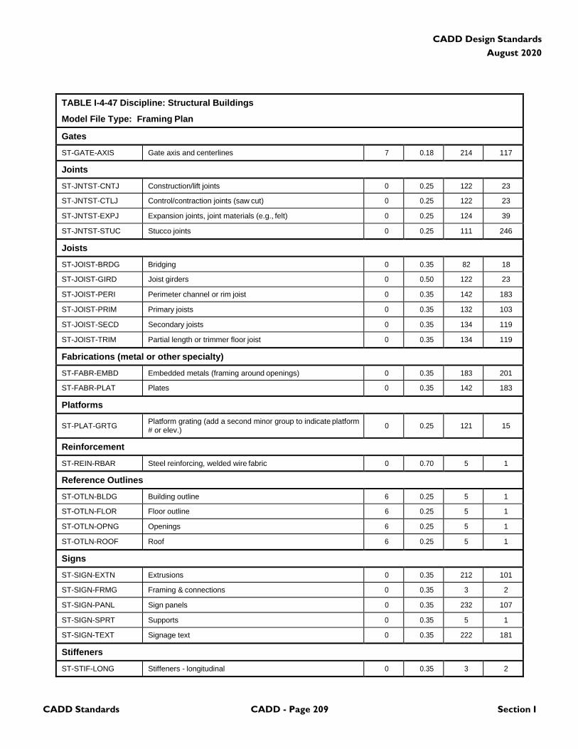
CADD Standards CADD - Page 209 Section I
CADD Design Standards
August 2020
TABLE I-4-47 Discipline: Structural Buildings
Model File Type: Framing Plan
Gates
ST-GATE-AXIS Gate axis and centerlines 7 0.18 214 117
Joints
ST-JNTST-CNTJ Construction/lift joints 0 0.25 122 23
ST-JNTST-CTLJ Control/contraction joints (saw cut) 0 0.25 122 23
ST-JNTST-EXPJ Expansion joints, joint materials (e.g., felt) 0 0.25 124 39
ST-JNTST-STUC Stucco joints 0 0.25 111 246
Joists
ST-JOIST-BRDG Bridging 0 0.35 82 18
ST-JOIST-GIRD Joist girders 0 0.50 122 23
ST-JOIST-PERI Perimeter channel or rim joist 0 0.35 142 183
ST-JOIST-PRIM Primary joists 0 0.35 132 103
ST-JOIST-SECD Secondary joists 0 0.35 134 119
ST-JOIST-TRIM Partial length or trimmer floor joist 0 0.35 134 119
Fabrications (metal or other specialty)
ST-FABR-EMBD Embedded metals (framing around openings) 0 0.35 183 201
ST-FABR-PLAT Plates 0 0.35 142 183
Platforms
ST-PLAT-GRTG Platform grating (add a second minor group to indicate platform # or elev.)
0
0.25
121
15
Reinforcement
ST-REIN-RBAR Steel reinforcing, welded wire fabric 0 0.70 5 1
Reference Outlines
ST-OTLN-BLDG Building outline 6 0.25 5 1
ST-OTLN-FLOR Floor outline 6 0.25 5 1
ST-OTLN-OPNG Openings 6 0.25 5 1
ST-OTLN-ROOF Roof 6 0.25 5 1
Signs
ST-SIGN-EXTN Extrusions 0 0.35 212 101
ST-SIGN-FRMG Framing & connections 0 0.35 3 2
ST-SIGN-PANL Sign panels 0 0.35 232 107
ST-SIGN-SPRT Supports 0 0.35 5 1
ST-SIGN-TEXT Signage text 0 0.35 222 181
Stiffeners
ST-STIF-LONG Stiffeners - longitudinal 0 0.35 3 2
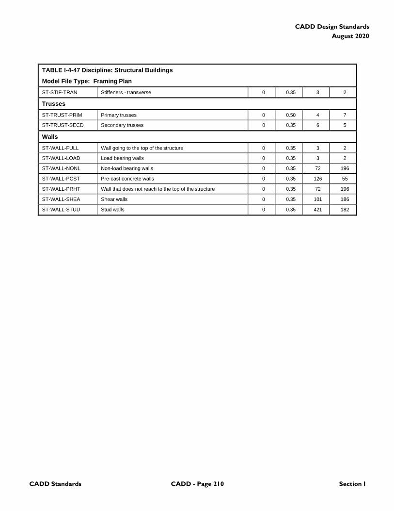
CADD Standards CADD - Page 210 Section I
CADD Design Standards
August 2020
TABLE I-4-47 Discipline: Structural Buildings
Model File Type: Framing Plan
ST-STIF-TRAN Stiffeners - transverse 0 0.35 3 2
Trusses
ST-TRUST-PRIM Primary trusses 0 0.50 4 7
ST-TRUST-SECD Secondary trusses 0 0.35 6 5
Walls
ST-WALL-FULL Wall going to the top of the structure 0 0.35 3 2
ST-WALL-LOAD Load bearing walls 0 0.35 3 2
ST-WALL-NONL Non-load bearing walls 0 0.35 72 196
ST-WALL-PCST Pre-cast concrete walls 0 0.35 126 55
ST-WALL-PRHT Wall that does not reach to the top of the structure 0 0.35 72 196
ST-WALL-SHEA Shear walls 0 0.35 101 186
ST-WALL-STUD Stud walls 0 0.35 421 182
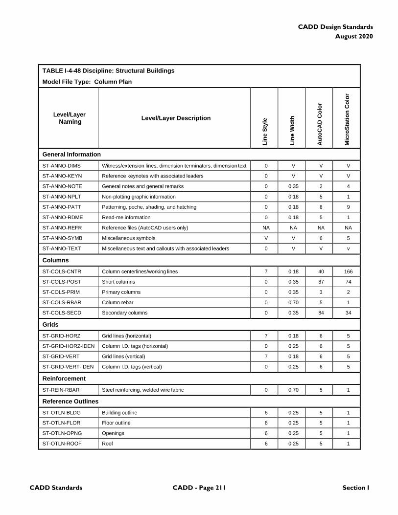
CADD Standards CADD - Page 211 Section I
CADD Design Standards
August 2020
TABLE I-4-48 Discipline: Structural Buildings
Model File Type: Column Plan
Level/Layer
Naming
Level/Layer Description
Lin
e S
tyle
Lin
e W
idth
Au
toC
AD
Co
lor
Mic
roS
tati
on
Co
lor
General Information
ST-ANNO-DIMS Witness/extension lines, dimension terminators, dimension text 0 V V V
ST-ANNO-KEYN Reference keynotes with associated leaders 0 V V V
ST-ANNO-NOTE General notes and general remarks 0 0.35 2 4
ST-ANNO-NPLT Non-plotting graphic information 0 0.18 5 1
ST-ANNO-PATT Patterning, poche, shading, and hatching 0 0.18 8 9
ST-ANNO-RDME Read-me information 0 0.18 5 1
ST-ANNO-REFR Reference files (AutoCAD users only) NA NA NA NA
ST-ANNO-SYMB Miscellaneous symbols V V 6 5
ST-ANNO-TEXT Miscellaneous text and callouts with associated leaders 0 V V v
Columns
ST-COLS-CNTR Column centerlines/working lines 7 0.18 40 166
ST-COLS-POST Short columns 0 0.35 87 74
ST-COLS-PRIM Primary columns 0 0.35 3 2
ST-COLS-RBAR Column rebar 0 0.70 5 1
ST-COLS-SECD Secondary columns 0 0.35 84 34
Grids
ST-GRID-HORZ Grid lines (horizontal) 7 0.18 6 5
ST-GRID-HORZ-IDEN Column I.D. tags (horizontal) 0 0.25 6 5
ST-GRID-VERT Grid lines (vertical) 7 0.18 6 5
ST-GRID-VERT-IDEN Column I.D. tags (vertical) 0 0.25 6 5
Reinforcement
ST-REIN-RBAR Steel reinforcing, welded wire fabric 0 0.70 5 1
Reference Outlines
ST-OTLN-BLDG Building outline 6 0.25 5 1
ST-OTLN-FLOR Floor outline 6 0.25 5 1
ST-OTLN-OPNG Openings 6 0.25 5 1
ST-OTLN-ROOF Roof 6 0.25 5 1
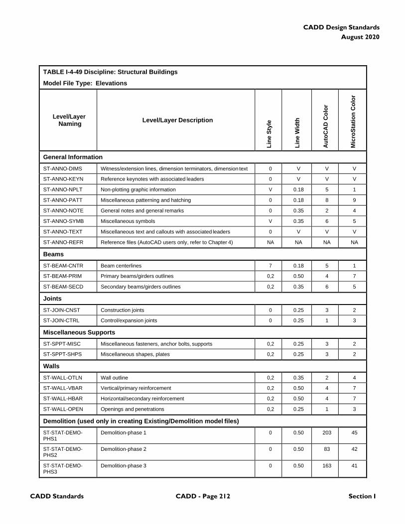
CADD Standards CADD - Page 212 Section I
CADD Design Standards
August 2020
TABLE I-4-49 Discipline: Structural Buildings
Model File Type: Elevations
Level/Layer
Naming
Level/Layer Description
Lin
e S
tyle
Lin
e W
idth
Au
toC
AD
Co
lor
Mic
roS
tati
on
Co
lor
General Information
ST-ANNO-DIMS Witness/extension lines, dimension terminators, dimension text 0 V V V
ST-ANNO-KEYN Reference keynotes with associated leaders 0 V V V
ST-ANNO-NPLT Non-plotting graphic information V 0.18 5 1
ST-ANNO-PATT Miscellaneous patterning and hatching 0 0.18 8 9
ST-ANNO-NOTE General notes and general remarks 0 0.35 2 4
ST-ANNO-SYMB Miscellaneous symbols V 0.35 6 5
ST-ANNO-TEXT Miscellaneous text and callouts with associated leaders 0 V V V
ST-ANNO-REFR Reference files (AutoCAD users only, refer to Chapter 4) NA NA NA NA
Beams
ST-BEAM-CNTR Beam centerlines 7 0.18 5 1
ST-BEAM-PRIM Primary beams/girders outlines 0,2 0.50 4 7
ST-BEAM-SECD Secondary beams/girders outlines 0,2 0.35 6 5
Joints
ST-JOIN-CNST Construction joints 0 0.25 3 2
ST-JOIN-CTRL Control/expansion joints 0 0.25 1 3
Miscellaneous Supports
ST-SPPT-MISC Miscellaneous fasteners, anchor bolts, supports 0,2 0.25 3 2
ST-SPPT-SHPS Miscellaneous shapes, plates 0,2 0.25 3 2
Walls
ST-WALL-OTLN Wall outline 0,2 0.35 2 4
ST-WALL-VBAR Vertical/primary reinforcement 0,2 0.50 4 7
ST-WALL-HBAR Horizontal/secondary reinforcement 0,2 0.50 4 7
ST-WALL-OPEN Openings and penetrations 0,2 0.25 1 3
Demolition (used only in creating Existing/Demolition model files)
ST-STAT-DEMO- PHS1
Demolition-phase 1 0 0.50 203 45
ST-STAT-DEMO- PHS2
Demolition-phase 2 0 0.50 83 42
ST-STAT-DEMO- PHS3
Demolition-phase 3 0 0.50 163 41
CADD Standards CADD - Page 213 Section I
CADD Design Standards
August 2020
TABLE I-4-49 Discipline: Structural Buildings
Model File Type: Elevations
Note: V=Varies, NA=Not Applicable
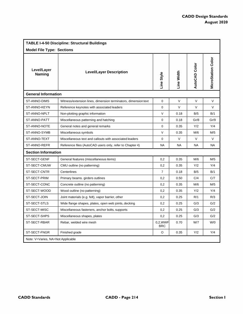
CADD Standards CADD - Page 214 Section I
CADD Design Standards
August 2020
TABLE I-4-50 Discipline: Structural Buildings
Model File Type: Sections
Level/Layer
Naming
Level/Layer Description
Lin
e S
tyle
Lin
e W
idth
Au
toC
AD
Co
lor
Mic
roS
tati
on
Co
lor
General Information
ST-ANNO-DIMS Witness/extension lines, dimension terminators, dimension text 0 V V V
ST-ANNO-KEYN Reference keynotes with associated leaders 0 V V V
ST-ANNO-NPLT Non-plotting graphic information V 0.18 B/5 B/1
ST-ANNO-PATT Miscellaneous patterning and hatching 0 0.18 Gr/8 Gr/9
ST-ANNO-NOTE General notes and general remarks 0 0.35 Y/2 Y/4
ST-ANNO-SYMB Miscellaneous symbols V 0.35 M/6 M/5
ST-ANNO-TEXT Miscellaneous text and callouts with associated leaders 0 V V V
ST-ANNO-REFR Reference files (AutoCAD users only, refer to Chapter 4) NA NA NA NA
Section Information
ST-SECT-GENF General features (miscellaneous items) 0,2 0.35 M/6 M/5
ST-SECT-CMUW CMU outline (no patterning) 0,2 0.35 Y/2 Y/4
ST-SECT-CNTR Centerlines 7 0.18 B/5 B/1
ST-SECT-PRIM Primary beams. girders outlines 0,2 0.50 C/4 C/7
ST-SECT-CONC Concrete outline (no patterning) 0,2 0.35 M/6 M/5
ST-SECT-WOOD Wood outline (no patterning) 0,2 0.35 Y/2 Y/4
ST-SECT-JOIN Joint materials (e.g. felt), vapor barrier, other 0,2 0.25 R/1 R/3
ST-SECT-STLS Wide flange shapes, plates, open web joints, decking 0,2 0.25 G/3 G/2
ST-SECT-MISC Miscellaneous fasteners, anchor bolts, supports 0,2 0.25 G/3 G/2
ST-SECT-SHPS Miscellaneous shapes, plates 0,2 0.25 G/3 G/2
ST-SECT-RBAR Rebar, welded wire mesh 0,2,WWF BRC
0.70 W/7 W/0
ST-SECT-FNGR Finished grade O 0.35 Y/2 Y/4
Note: V=Varies, NA=Not Applicable

CADD Standards CADD - Page 215 Section I
CADD Design Standards
August 2020
TABLE I-4-51 Discipline: Structural Buildings
Model File Type: Details
Level/Layer
Naming
Level/Layer Description
Lin
e S
tyle
Lin
e W
idth
Au
toC
AD
Co
lor
Mic
roS
tati
on
Co
lor
General Information
ST-ANNO-DIMS Witness/extension lines, dimension terminators, dimension text, welding symbols
0 V V V
ST-ANNO-KEYN Reference keynotes with associated leaders 0 V V V
ST-ANNO-NPLT Non-plotting graphic information V 0.18 B/5 B/1
ST-ANNO-PATT Miscellaneous patterning and hatching 0 0.18 Gr/8 Gr/9
ST-ANNO-NOTE General notes and general remarks 0 0.35 Y/2 Y/4
ST-ANNO-SYMB Miscellaneous symbols V 0.35 M/6 M/5
ST-ANNO-TEXT Miscellaneous text and callouts with associated leaders 0 V V V
ST-ANNO-REFR Reference files (AutoCAD users only, refer to Chapter 4) NA NA NA NA
Detail Information
ST-DETL-GRPH Graphics, gridlines, non-text items V V V V
ST-DETL-METR Metric-specific dimensions and notes 0 0.35 Y/2 Y/4
ST-DETL-INPD Inch-pound-specific dimensions and notes 0 0.35 Y/2 Y/4
Demolition
ST-STAT-DEMO- PHS1
Demolition-phase 1 0 0.50 203 45
ST-STAT-DEMO- PHS2
Demolition-phase 2 0 0.50 83 42
ST-STAT-DEMO- PHS3
Demolition-phase 3 0 0.50 163 41
Note: V=Varies, NA=Not Applicable

CADD Standards CADD - Page 216 Section I
CADD Design Standards
August 2020
4.11 Structural Civil
TABLE I-4-52 Discipline: Structural Civil
Model File Type: Substructure
Level/Layer
Naming
Level/Layer Description
Lin
e S
tyle
Lin
e W
idth
Au
toC
AD
Co
lor
Mic
roS
tati
on
Co
lor
General Information
SC-ANNO-DIMS Witness/extension lines, dimension terminators, dimension text 0 V V V
SC-ANNO-KEYN Reference keynotes with associated leaders 0 V V V
SC-ANNO-NOTE General notes and general remarks 0 0.35 2 4
SC-ANNO-NPLT Non-plotting graphic information 0 0.18 5 1
SC-ANNO-PATT Patterning, poche, shading, and hatching 0 0.18 8 9
SC-ANNO-RDME Read-me information 0 0.18 5 1
SC-ANNO-REFR Reference files (AutoCAD users only) NA NA NA NA
SC-ANNO-SYMB Miscellaneous symbols V V 6 5
SC-ANNO-TEXT Miscellaneous text and callouts with associated leaders 0 V V v
Access
SC-ACCS-LADD Ladders and ladder safety devices 0 0.35 162 33
SC-ACCS-MHOL Manholes 0 0.35 83 42
SC-ACCS-MISC Miscellaneous access 0 0.35 83 42
SC-ACCS-STRS Stairs 0 0.35 133 111
SC-ACCS-STRS- FRMG
Stair framing
0
0.35
135
127
SC-ACCS-TUNL Tunnels 0 0.35 42 182
Bridges
SC-BRDG-ABUT Abutments 0 0.50 83 42
SC-BRDG-ABUT- RBAR
Abutment rebar
0
0.70
5
1
SC-BRDG-BEAR Bridge bearing 0 0.35 152 88
SC-BRDG-BEAR- CNTR
Bridge bearing centerlines
7
0.18
214
117
SC-BRDG-BENT Bent cap 0 0.35 3 2
SC-BRDG-BENT- CNTR
Centerline of bents
7
0.18
214
117
SC-BRDG-BENT- RBAR
Bent cap rebar
0
0.70
5
1
SC-BRDG-PIER Piers 0 0.50 83 42
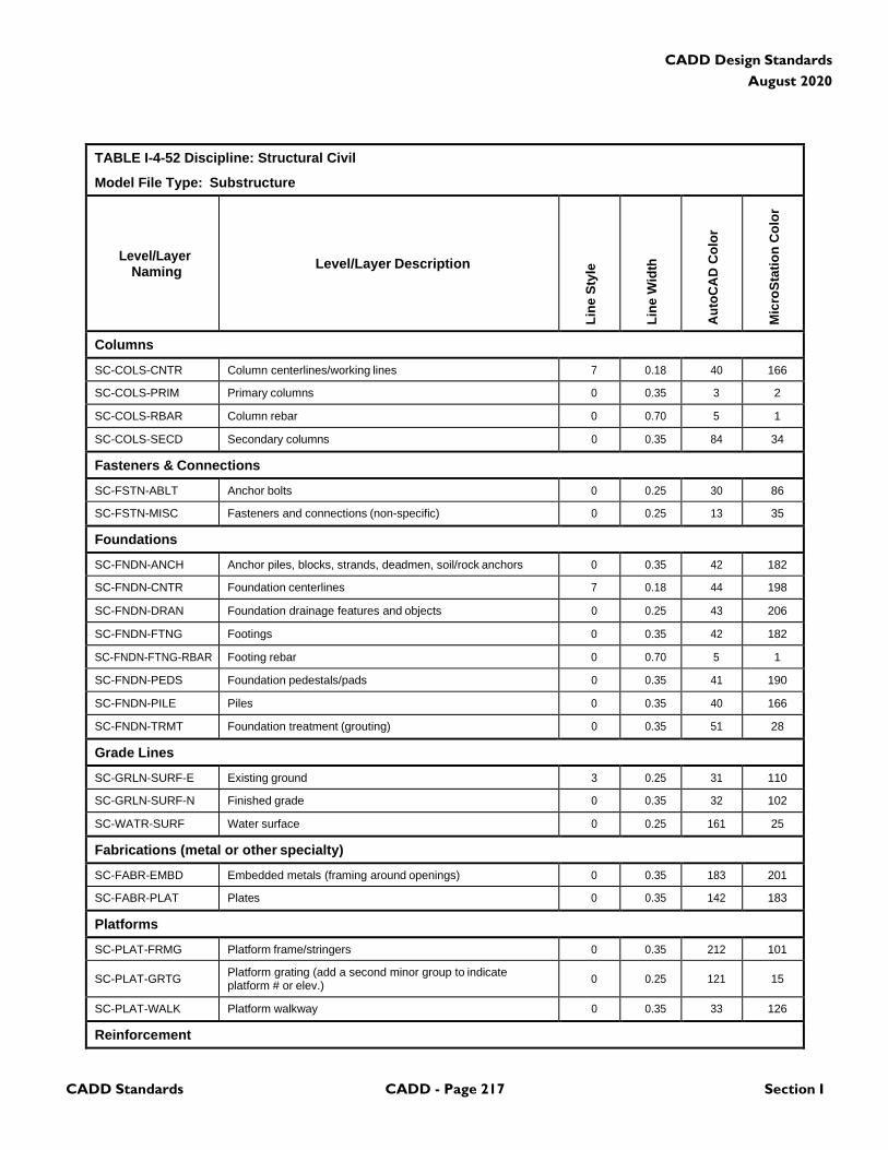
CADD Standards CADD - Page 217 Section I
CADD Design Standards
August 2020
TABLE I-4-52 Discipline: Structural Civil
Model File Type: Substructure
Level/Layer
Naming
Level/Layer Description
Lin
e S
tyle
Lin
e W
idth
Au
toC
AD
Co
lor
Mic
roS
tati
on
Co
lor
Columns
SC-COLS-CNTR Column centerlines/working lines 7 0.18 40 166
SC-COLS-PRIM Primary columns 0 0.35 3 2
SC-COLS-RBAR Column rebar 0 0.70 5 1
SC-COLS-SECD Secondary columns 0 0.35 84 34
Fasteners & Connections
SC-FSTN-ABLT Anchor bolts 0 0.25 30 86
SC-FSTN-MISC Fasteners and connections (non-specific) 0 0.25 13 35
Foundations
SC-FNDN-ANCH Anchor piles, blocks, strands, deadmen, soil/rock anchors 0 0.35 42 182
SC-FNDN-CNTR Foundation centerlines 7 0.18 44 198
SC-FNDN-DRAN Foundation drainage features and objects 0 0.25 43 206
SC-FNDN-FTNG Footings 0 0.35 42 182
SC-FNDN-FTNG-RBAR Footing rebar 0 0.70 5 1
SC-FNDN-PEDS Foundation pedestals/pads 0 0.35 41 190
SC-FNDN-PILE Piles 0 0.35 40 166
SC-FNDN-TRMT Foundation treatment (grouting) 0 0.35 51 28
Grade Lines
SC-GRLN-SURF-E Existing ground 3 0.25 31 110
SC-GRLN-SURF-N Finished grade 0 0.35 32 102
SC-WATR-SURF Water surface 0 0.25 161 25
Fabrications (metal or other specialty)
SC-FABR-EMBD Embedded metals (framing around openings) 0 0.35 183 201
SC-FABR-PLAT Plates 0 0.35 142 183
Platforms
SC-PLAT-FRMG Platform frame/stringers 0 0.35 212 101
SC-PLAT-GRTG Platform grating (add a second minor group to indicate platform # or elev.)
0
0.25
121
15
SC-PLAT-WALK Platform walkway 0 0.35 33 126
Reinforcement
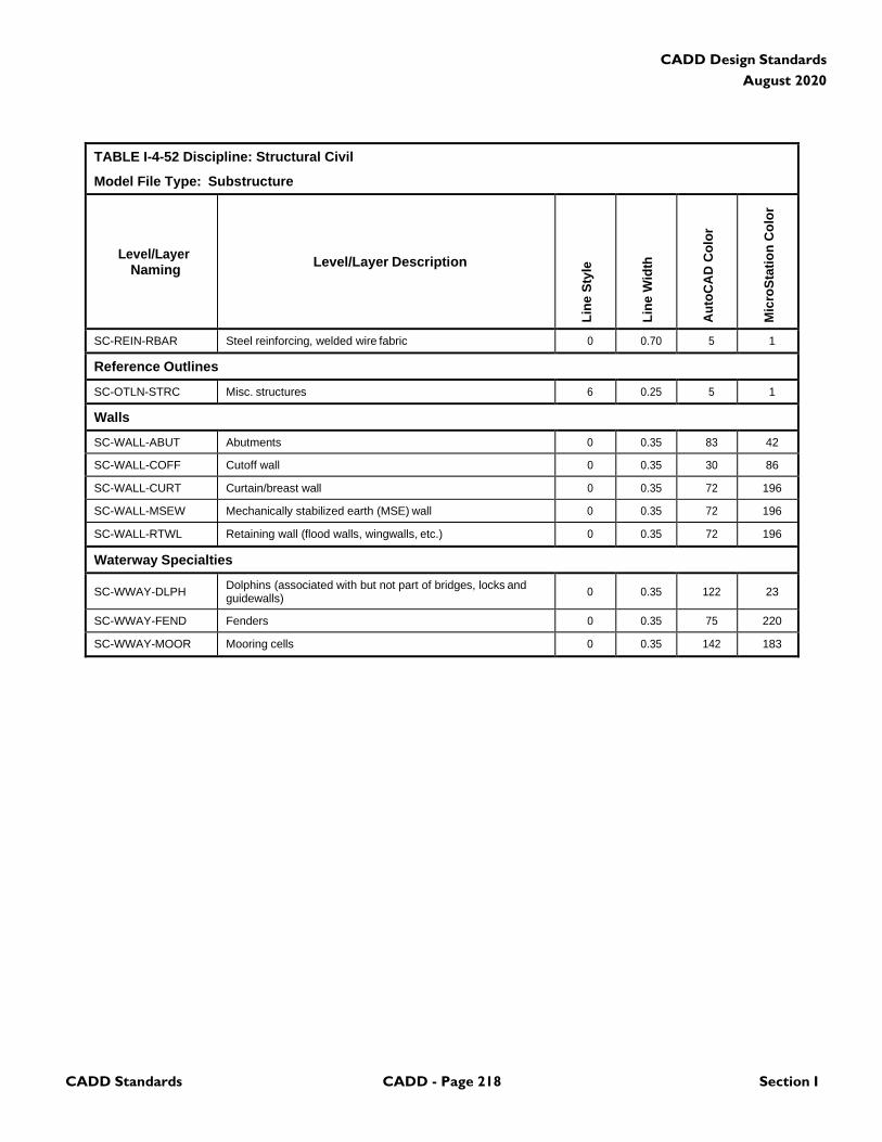
CADD Standards CADD - Page 218 Section I
CADD Design Standards
August 2020
TABLE I-4-52 Discipline: Structural Civil
Model File Type: Substructure
Level/Layer
Naming
Level/Layer Description
Lin
e S
tyle
Lin
e W
idth
Au
toC
AD
Co
lor
Mic
roS
tati
on
Co
lor
SC-REIN-RBAR Steel reinforcing, welded wire fabric 0 0.70 5 1
Reference Outlines
SC-OTLN-STRC Misc. structures 6 0.25 5 1
Walls
SC-WALL-ABUT Abutments 0 0.35 83 42
SC-WALL-COFF Cutoff wall 0 0.35 30 86
SC-WALL-CURT Curtain/breast wall 0 0.35 72 196
SC-WALL-MSEW Mechanically stabilized earth (MSE) wall 0 0.35 72 196
SC-WALL-RTWL Retaining wall (flood walls, wingwalls, etc.) 0 0.35 72 196
Waterway Specialties
SC-WWAY-DLPH Dolphins (associated with but not part of bridges, locks and guidewalls)
0
0.35
122
23
SC-WWAY-FEND Fenders 0 0.35 75 220
SC-WWAY-MOOR Mooring cells 0 0.35 142 183
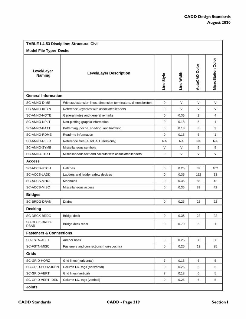
CADD Standards CADD - Page 219 Section I
CADD Design Standards
August 2020
TABLE I-4-53 Discipline: Structural Civil
Model File Type: Decks
Level/Layer
Naming
Level/Layer Description
Lin
e S
tyle
Lin
e W
idth
Au
toC
AD
Co
lor
Mic
roS
tati
on
Co
lor
General Information
SC-ANNO-DIMS Witness/extension lines, dimension terminators, dimension text 0 V V V
SC-ANNO-KEYN Reference keynotes with associated leaders 0 V V V
SC-ANNO-NOTE General notes and general remarks 0 0.35 2 4
SC-ANNO-NPLT Non-plotting graphic information 0 0.18 5 1
SC-ANNO-PATT Patterning, poche, shading, and hatching 0 0.18 8 9
SC-ANNO-RDME Read-me information 0 0.18 5 1
SC-ANNO-REFR Reference files (AutoCAD users only) NA NA NA NA
SC-ANNO-SYMB Miscellaneous symbols V V 6 5
SC-ANNO-TEXT Miscellaneous text and callouts with associated leaders 0 V V v
Access
SC-ACCS-HTCH Hatches 0 0.25 32 102
SC-ACCS-LADD Ladders and ladder safety devices 0 0.35 162 33
SC-ACCS-MHOL Manholes 0 0.35 83 42
SC-ACCS-MISC Miscellaneous access 0 0.35 83 42
Bridges
SC-BRDG-DRAN Drains 0 0.25 22 22
Decking
SC-DECK-BRDG Bridge deck 0 0.35 22 22
SC-DECK-BRDG- RBAR
Bridge deck rebar
0
0.70
5
1
Fasteners & Connections
SC-FSTN-ABLT Anchor bolts 0 0.25 30 86
SC-FSTN-MISC Fasteners and connections (non-specific) 0 0.25 13 35
Grids
SC-GRID-HORZ Grid lines (horizontal) 7 0.18 6 5
SC-GRID-HORZ-IDEN Column I.D. tags (horizontal) 0 0.25 6 5
SC-GRID-VERT Grid lines (vertical) 7 0.18 6 5
SC-GRID-VERT-IDEN Column I.D. tags (vertical) 0 0.25 6 5
Joints
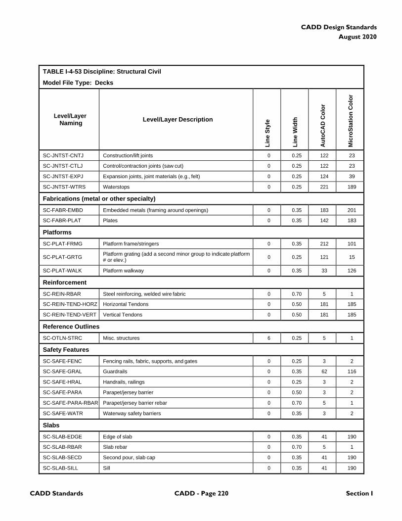
CADD Standards CADD - Page 220 Section I
CADD Design Standards
August 2020
TABLE I-4-53 Discipline: Structural Civil
Model File Type: Decks
Level/Layer
Naming
Level/Layer Description
Lin
e S
tyle
Lin
e W
idth
Au
toC
AD
Co
lor
Mic
roS
tati
on
Co
lor
SC-JNTST-CNTJ Construction/lift joints 0 0.25 122 23
SC-JNTST-CTLJ Control/contraction joints (saw cut) 0 0.25 122 23
SC-JNTST-EXPJ Expansion joints, joint materials (e.g., felt) 0 0.25 124 39
SC-JNTST-WTRS Waterstops 0 0.25 221 189
Fabrications (metal or other specialty)
SC-FABR-EMBD Embedded metals (framing around openings) 0 0.35 183 201
SC-FABR-PLAT Plates 0 0.35 142 183
Platforms
SC-PLAT-FRMG Platform frame/stringers 0 0.35 212 101
SC-PLAT-GRTG Platform grating (add a second minor group to indicate platform # or elev.)
0
0.25
121
15
SC-PLAT-WALK Platform walkway 0 0.35 33 126
Reinforcement
SC-REIN-RBAR Steel reinforcing, welded wire fabric 0 0.70 5 1
SC-REIN-TEND-HORZ Horizontal Tendons 0 0.50 181 185
SC-REIN-TEND-VERT Vertical Tendons 0 0.50 181 185
Reference Outlines
SC-OTLN-STRC Misc. structures 6 0.25 5 1
Safety Features
SC-SAFE-FENC Fencing rails, fabric, supports, and gates 0 0.25 3 2
SC-SAFE-GRAL Guardrails 0 0.35 62 116
SC-SAFE-HRAL Handrails, railings 0 0.25 3 2
SC-SAFE-PARA Parapet/jersey barrier 0 0.50 3 2
SC-SAFE-PARA-RBAR Parapet/jersey barrier rebar 0 0.70 5 1
SC-SAFE-WATR Waterway safety barriers 0 0.35 3 2
Slabs
SC-SLAB-EDGE Edge of slab 0 0.35 41 190
SC-SLAB-RBAR Slab rebar 0 0.70 5 1
SC-SLAB-SECD Second pour, slab cap 0 0.35 41 190
SC-SLAB-SILL Sill 0 0.35 41 190
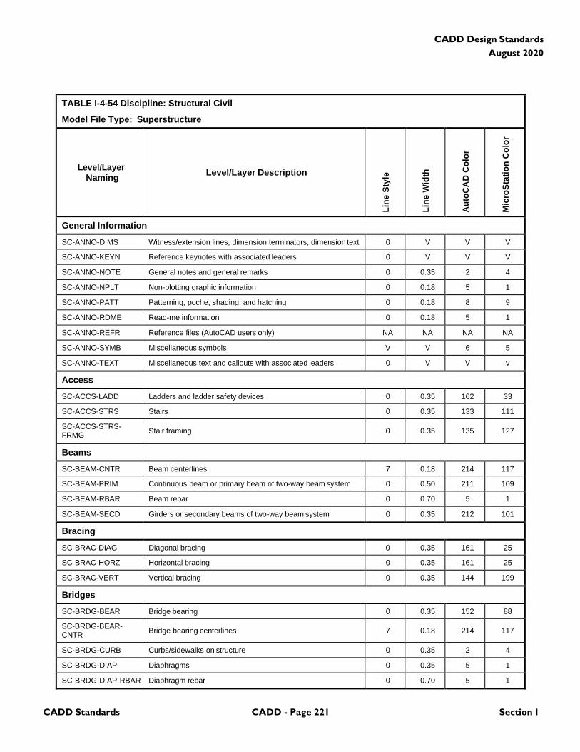
CADD Standards CADD - Page 221 Section I
CADD Design Standards
August 2020
TABLE I-4-54 Discipline: Structural Civil
Model File Type: Superstructure
Level/Layer
Naming
Level/Layer Description
Lin
e S
tyle
Lin
e W
idth
Au
toC
AD
Co
lor
Mic
roS
tati
on
Co
lor
General Information
SC-ANNO-DIMS Witness/extension lines, dimension terminators, dimension text 0 V V V
SC-ANNO-KEYN Reference keynotes with associated leaders 0 V V V
SC-ANNO-NOTE General notes and general remarks 0 0.35 2 4
SC-ANNO-NPLT Non-plotting graphic information 0 0.18 5 1
SC-ANNO-PATT Patterning, poche, shading, and hatching 0 0.18 8 9
SC-ANNO-RDME Read-me information 0 0.18 5 1
SC-ANNO-REFR Reference files (AutoCAD users only) NA NA NA NA
SC-ANNO-SYMB Miscellaneous symbols V V 6 5
SC-ANNO-TEXT Miscellaneous text and callouts with associated leaders 0 V V v
Access
SC-ACCS-LADD Ladders and ladder safety devices 0 0.35 162 33
SC-ACCS-STRS Stairs 0 0.35 133 111
SC-ACCS-STRS- FRMG
Stair framing
0
0.35
135
127
Beams
SC-BEAM-CNTR Beam centerlines 7 0.18 214 117
SC-BEAM-PRIM Continuous beam or primary beam of two-way beam system 0 0.50 211 109
SC-BEAM-RBAR Beam rebar 0 0.70 5 1
SC-BEAM-SECD Girders or secondary beams of two-way beam system 0 0.35 212 101
Bracing
SC-BRAC-DIAG Diagonal bracing 0 0.35 161 25
SC-BRAC-HORZ Horizontal bracing 0 0.35 161 25
SC-BRAC-VERT Vertical bracing 0 0.35 144 199
Bridges
SC-BRDG-BEAR Bridge bearing 0 0.35 152 88
SC-BRDG-BEAR- CNTR
Bridge bearing centerlines
7
0.18
214
117
SC-BRDG-CURB Curbs/sidewalks on structure 0 0.35 2 4
SC-BRDG-DIAP Diaphragms 0 0.35 5 1
SC-BRDG-DIAP-RBAR Diaphragm rebar 0 0.70 5 1
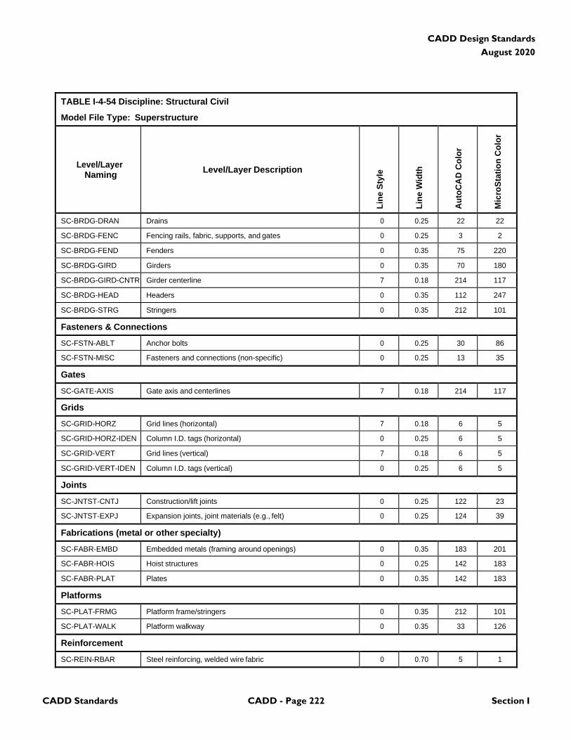
CADD Standards CADD - Page 222 Section I
CADD Design Standards
August 2020
TABLE I-4-54 Discipline: Structural Civil
Model File Type: Superstructure
Level/Layer
Naming
Level/Layer Description
Lin
e S
tyle
Lin
e W
idth
Au
toC
AD
Co
lor
Mic
roS
tati
on
Co
lor
SC-BRDG-DRAN Drains 0 0.25 22 22
SC-BRDG-FENC Fencing rails, fabric, supports, and gates 0 0.25 3 2
SC-BRDG-FEND Fenders 0 0.35 75 220
SC-BRDG-GIRD Girders 0 0.35 70 180
SC-BRDG-GIRD-CNTR Girder centerline 7 0.18 214 117
SC-BRDG-HEAD Headers 0 0.35 112 247
SC-BRDG-STRG Stringers 0 0.35 212 101
Fasteners & Connections
SC-FSTN-ABLT Anchor bolts 0 0.25 30 86
SC-FSTN-MISC Fasteners and connections (non-specific) 0 0.25 13 35
Gates
SC-GATE-AXIS Gate axis and centerlines 7 0.18 214 117
Grids
SC-GRID-HORZ Grid lines (horizontal) 7 0.18 6 5
SC-GRID-HORZ-IDEN Column I.D. tags (horizontal) 0 0.25 6 5
SC-GRID-VERT Grid lines (vertical) 7 0.18 6 5
SC-GRID-VERT-IDEN Column I.D. tags (vertical) 0 0.25 6 5
Joints
SC-JNTST-CNTJ Construction/lift joints 0 0.25 122 23
SC-JNTST-EXPJ Expansion joints, joint materials (e.g., felt) 0 0.25 124 39
Fabrications (metal or other specialty)
SC-FABR-EMBD Embedded metals (framing around openings) 0 0.35 183 201
SC-FABR-HOIS Hoist structures 0 0.25 142 183
SC-FABR-PLAT Plates 0 0.35 142 183
Platforms
SC-PLAT-FRMG Platform frame/stringers 0 0.35 212 101
SC-PLAT-WALK Platform walkway 0 0.35 33 126
Reinforcement
SC-REIN-RBAR Steel reinforcing, welded wire fabric 0 0.70 5 1
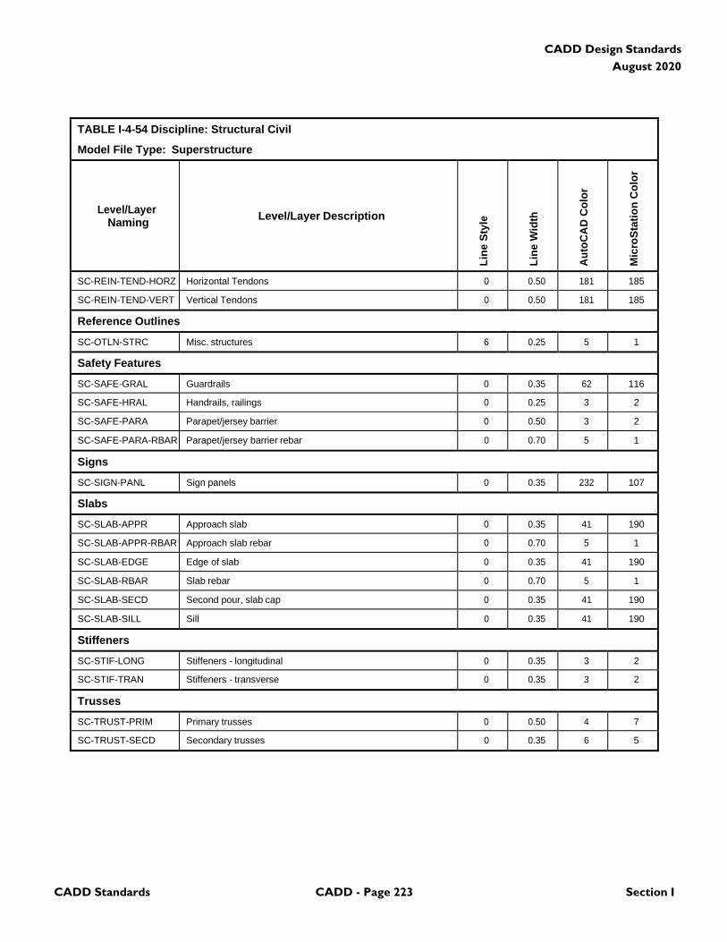
CADD Standards CADD - Page 223 Section I
CADD Design Standards
August 2020
TABLE I-4-54 Discipline: Structural Civil
Model File Type: Superstructure
Level/Layer
Naming
Level/Layer Description
Lin
e S
tyle
Lin
e W
idth
Au
toC
AD
Co
lor
Mic
roS
tati
on
Co
lor
SC-REIN-TEND-HORZ Horizontal Tendons 0 0.50 181 185
SC-REIN-TEND-VERT Vertical Tendons 0 0.50 181 185
Reference Outlines
SC-OTLN-STRC Misc. structures 6 0.25 5 1
Safety Features
SC-SAFE-GRAL Guardrails 0 0.35 62 116
SC-SAFE-HRAL Handrails, railings 0 0.25 3 2
SC-SAFE-PARA Parapet/jersey barrier 0 0.50 3 2
SC-SAFE-PARA-RBAR Parapet/jersey barrier rebar 0 0.70 5 1
Signs
SC-SIGN-PANL Sign panels 0 0.35 232 107
Slabs
SC-SLAB-APPR Approach slab 0 0.35 41 190
SC-SLAB-APPR-RBAR Approach slab rebar 0 0.70 5 1
SC-SLAB-EDGE Edge of slab 0 0.35 41 190
SC-SLAB-RBAR Slab rebar 0 0.70 5 1
SC-SLAB-SECD Second pour, slab cap 0 0.35 41 190
SC-SLAB-SILL Sill 0 0.35 41 190
Stiffeners
SC-STIF-LONG Stiffeners - longitudinal 0 0.35 3 2
SC-STIF-TRAN Stiffeners - transverse 0 0.35 3 2
Trusses
SC-TRUST-PRIM Primary trusses 0 0.50 4 7
SC-TRUST-SECD Secondary trusses 0 0.35 6 5
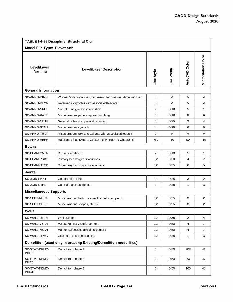
CADD Standards CADD - Page 224 Section I
CADD Design Standards
August 2020
TABLE I-4-55 Discipline: Structural Civil
Model File Type: Elevations
Level/Layer
Naming
Level/Layer Description
Lin
e S
tyle
Lin
e W
idth
Au
toC
AD
Co
lor
Mic
roS
tati
on
Co
lor
General Information
SC-ANNO-DIMS Witness/extension lines, dimension terminators, dimension text 0 V V V
SC-ANNO-KEYN Reference keynotes with associated leaders 0 V V V
SC-ANNO-NPLT Non-plotting graphic information V 0.18 5 1
SC-ANNO-PATT Miscellaneous patterning and hatching 0 0.18 8 9
SC-ANNO-NOTE General notes and general remarks 0 0.35 2 4
SC-ANNO-SYMB Miscellaneous symbols V 0.35 6 5
SC-ANNO-TEXT Miscellaneous text and callouts with associated leaders 0 V V V
SC-ANNO-REFR Reference files (AutoCAD users only, refer to Chapter 4) NA NA NA NA
Beams
SC-BEAM-CNTR Beam centerlines 7 0.18 5 1
SC-BEAM-PRIM Primary beams/girders outlines 0,2 0.50 4 7
SC-BEAM-SECD Secondary beams/girders outlines 0,2 0.35 6 5
Joints
SC-JOIN-CNST Construction joints 0 0.25 3 2
SC-JOIN-CTRL Control/expansion joints 0 0.25 1 3
Miscellaneous Supports
SC-SPPT-MISC Miscellaneous fasteners, anchor bolts, supports 0,2 0.25 3 2
SC-SPPT-SHPS Miscellaneous shapes, plates 0,2 0.25 3 2
Walls
SC-WALL-OTLN Wall outline 0,2 0.35 2 4
SC-WALL-VBAR Vertical/primary reinforcement 0,2 0.50 4 7
SC-WALL-HBAR Horizontal/secondary reinforcement 0,2 0.50 4 7
SC-WALL-OPEN Openings and penetrations 0,2 0.25 1 3
Demolition (used only in creating Existing/Demolition model files)
SC-STAT-DEMO- PHS1
Demolition-phase 1 0 0.50 203 45
SC-STAT-DEMO- PHS2
Demolition-phase 2 0 0.50 83 42
SC-STAT-DEMO- PHS3
Demolition-phase 3 0 0.50 163 41
CADD Standards CADD - Page 225 Section I
CADD Design Standards
August 2020
TABLE I-4-55 Discipline: Structural Civil
Model File Type: Elevations
Level/Layer
Naming
Level/Layer Description
Lin
e S
tyle
Lin
e W
idth
Au
toC
AD
Co
lor
Mic
roS
tati
on
Co
lor
Note: V=Varies, NA=Not Applicable
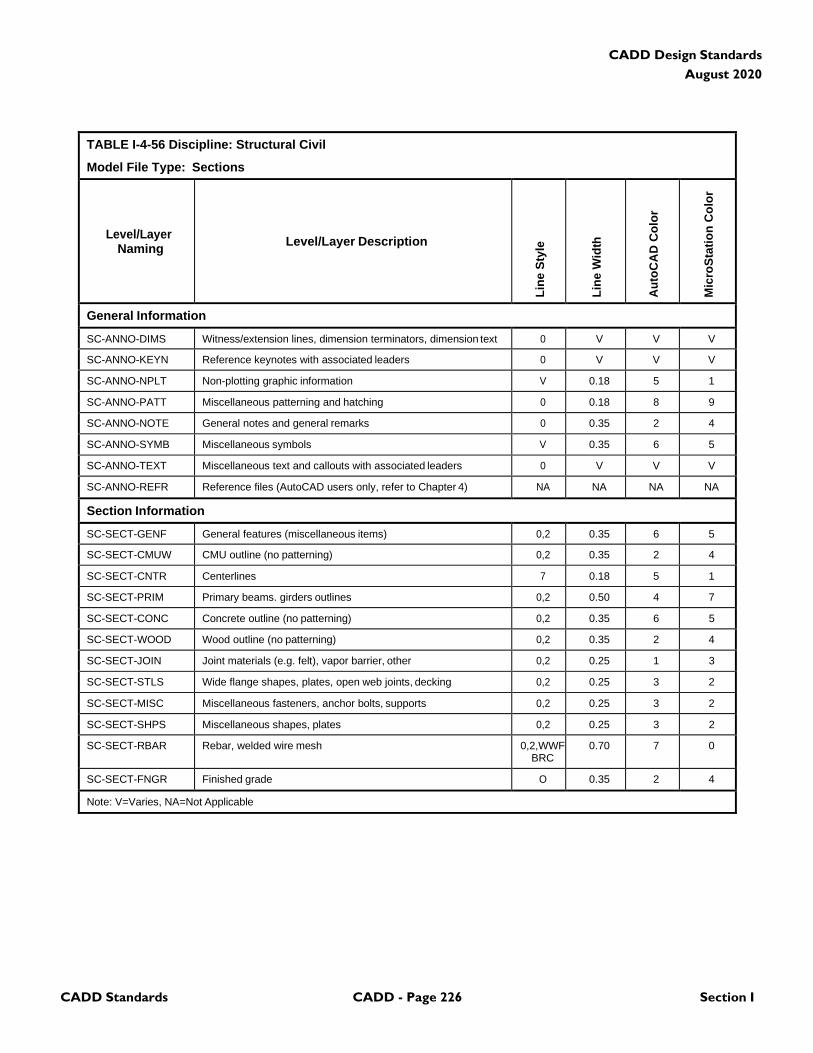
CADD Standards CADD - Page 226 Section I
CADD Design Standards
August 2020
TABLE I-4-56 Discipline: Structural Civil
Model File Type: Sections
Level/Layer
Naming
Level/Layer Description
Lin
e S
tyle
Lin
e W
idth
Au
toC
AD
Co
lor
Mic
roS
tati
on
Co
lor
General Information
SC-ANNO-DIMS Witness/extension lines, dimension terminators, dimension text 0 V V V
SC-ANNO-KEYN Reference keynotes with associated leaders 0 V V V
SC-ANNO-NPLT Non-plotting graphic information V 0.18 5 1
SC-ANNO-PATT Miscellaneous patterning and hatching 0 0.18 8 9
SC-ANNO-NOTE General notes and general remarks 0 0.35 2 4
SC-ANNO-SYMB Miscellaneous symbols V 0.35 6 5
SC-ANNO-TEXT Miscellaneous text and callouts with associated leaders 0 V V V
SC-ANNO-REFR Reference files (AutoCAD users only, refer to Chapter 4) NA NA NA NA
Section Information
SC-SECT-GENF General features (miscellaneous items) 0,2 0.35 6 5
SC-SECT-CMUW CMU outline (no patterning) 0,2 0.35 2 4
SC-SECT-CNTR Centerlines 7 0.18 5 1
SC-SECT-PRIM Primary beams. girders outlines 0,2 0.50 4 7
SC-SECT-CONC Concrete outline (no patterning) 0,2 0.35 6 5
SC-SECT-WOOD Wood outline (no patterning) 0,2 0.35 2 4
SC-SECT-JOIN Joint materials (e.g. felt), vapor barrier, other 0,2 0.25 1 3
SC-SECT-STLS Wide flange shapes, plates, open web joints, decking 0,2 0.25 3 2
SC-SECT-MISC Miscellaneous fasteners, anchor bolts, supports 0,2 0.25 3 2
SC-SECT-SHPS Miscellaneous shapes, plates 0,2 0.25 3 2
SC-SECT-RBAR Rebar, welded wire mesh 0,2,WWF BRC
0.70 7 0
SC-SECT-FNGR Finished grade O 0.35 2 4
Note: V=Varies, NA=Not Applicable
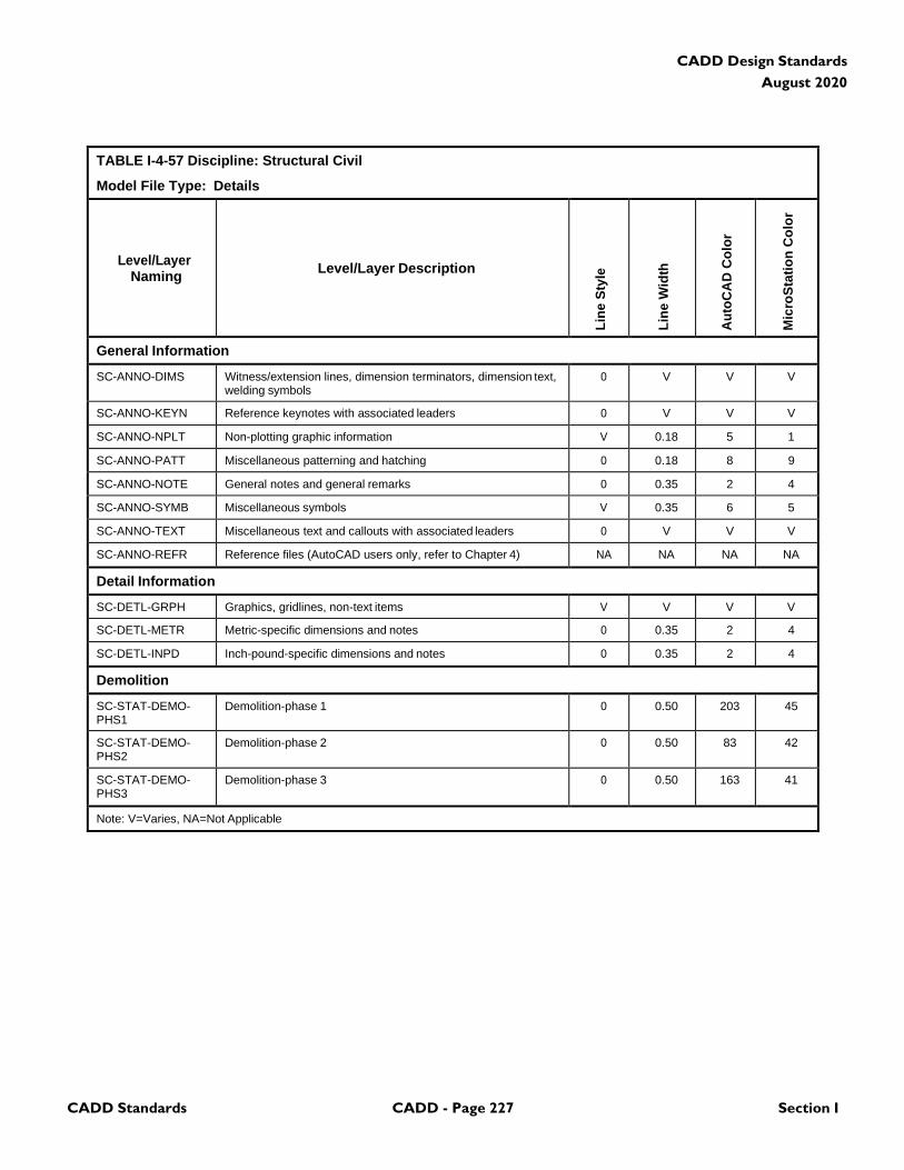
CADD Standards CADD - Page 227 Section I
CADD Design Standards
August 2020
TABLE I-4-57 Discipline: Structural Civil
Model File Type: Details
Level/Layer
Naming
Level/Layer Description
Lin
e S
tyle
Lin
e W
idth
Au
toC
AD
Co
lor
Mic
roS
tati
on
Co
lor
General Information
SC-ANNO-DIMS Witness/extension lines, dimension terminators, dimension text, welding symbols
0 V V V
SC-ANNO-KEYN Reference keynotes with associated leaders 0 V V V
SC-ANNO-NPLT Non-plotting graphic information V 0.18 5 1
SC-ANNO-PATT Miscellaneous patterning and hatching 0 0.18 8 9
SC-ANNO-NOTE General notes and general remarks 0 0.35 2 4
SC-ANNO-SYMB Miscellaneous symbols V 0.35 6 5
SC-ANNO-TEXT Miscellaneous text and callouts with associated leaders 0 V V V
SC-ANNO-REFR Reference files (AutoCAD users only, refer to Chapter 4) NA NA NA NA
Detail Information
SC-DETL-GRPH Graphics, gridlines, non-text items V V V V
SC-DETL-METR Metric-specific dimensions and notes 0 0.35 2 4
SC-DETL-INPD Inch-pound-specific dimensions and notes 0 0.35 2 4
Demolition
SC-STAT-DEMO- PHS1
Demolition-phase 1 0 0.50 203 45
SC-STAT-DEMO- PHS2
Demolition-phase 2 0 0.50 83 42
SC-STAT-DEMO- PHS3
Demolition-phase 3 0 0.50 163 41
Note: V=Varies, NA=Not Applicable
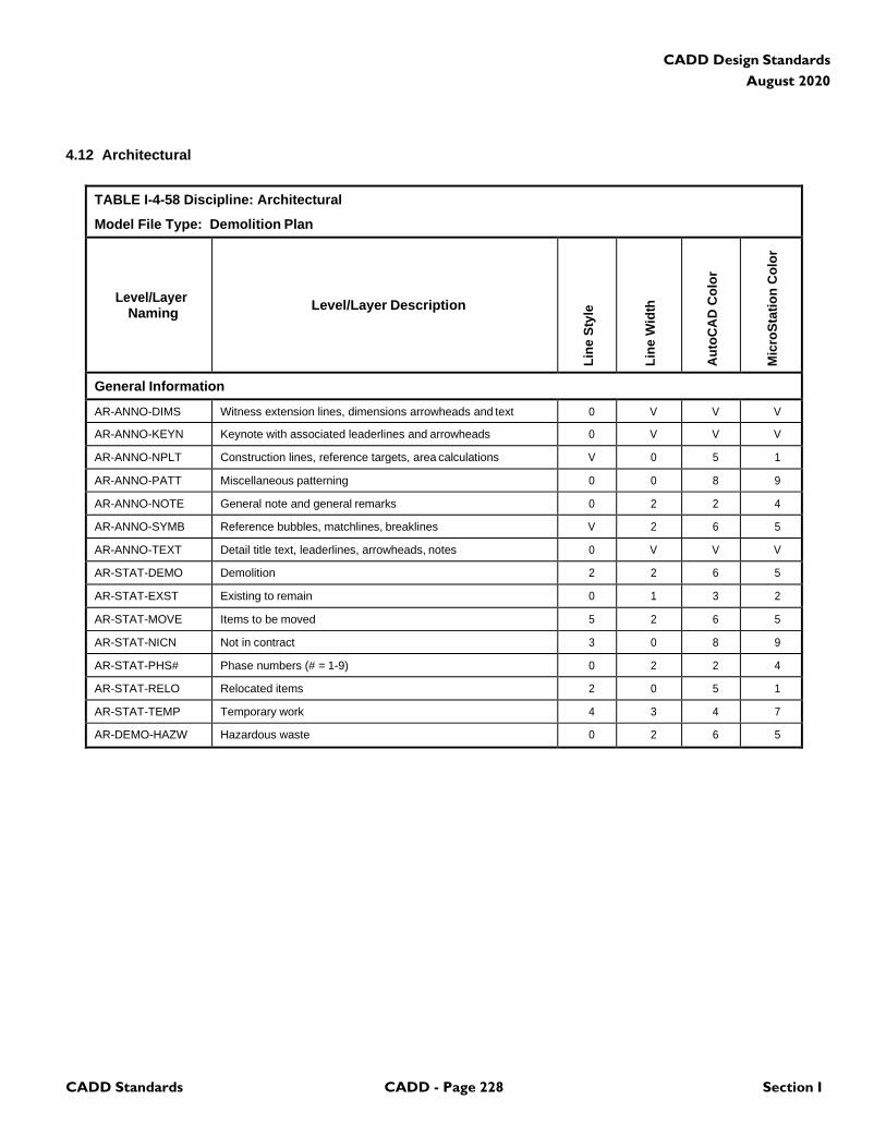
CADD Standards CADD - Page 228 Section I
CADD Design Standards
August 2020
4.12 Architectural
TABLE I-4-58 Discipline: Architectural
Model File Type: Demolition Plan
Level/Layer
Naming
Level/Layer Description
Lin
e S
tyle
Lin
e W
idth
Au
toC
AD
Co
lor
Mic
roS
tati
on
Co
lor
General Information
AR-ANNO-DIMS Witness extension lines, dimensions arrowheads and text 0 V V V
AR-ANNO-KEYN Keynote with associated leaderlines and arrowheads 0 V V V
AR-ANNO-NPLT Construction lines, reference targets, area calculations V 0 5 1
AR-ANNO-PATT Miscellaneous patterning 0 0 8 9
AR-ANNO-NOTE General note and general remarks 0 2 2 4
AR-ANNO-SYMB Reference bubbles, matchlines, breaklines V 2 6 5
AR-ANNO-TEXT Detail title text, leaderlines, arrowheads, notes 0 V V V
AR-STAT-DEMO Demolition 2 2 6 5
AR-STAT-EXST Existing to remain 0 1 3 2
AR-STAT-MOVE Items to be moved 5 2 6 5
AR-STAT-NICN Not in contract 3 0 8 9
AR-STAT-PHS# Phase numbers (# = 1-9) 0 2 2 4
AR-STAT-RELO Relocated items 2 0 5 1
AR-STAT-TEMP Temporary work 4 3 4 7
AR-DEMO-HAZW Hazardous waste 0 2 6 5
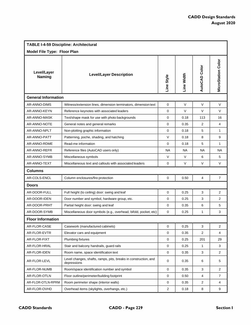
CADD Standards CADD - Page 229 Section I
CADD Design Standards
August 2020
TABLE I-4-59 Discipline: Architectural
Model File Type: Floor Plan
Level/Layer
Naming
Level/Layer Description
Lin
e S
tyle
Lin
e W
idth
Au
toC
AD
Co
lor
Mic
roS
tati
on
Co
lor
General Information
AR-ANNO-DIMS Witness/extension lines, dimension terminators, dimension text 0 V V V
AR-ANNO-KEYN Reference keynotes with associated leaders 0 V V V
AR-ANNO-MASK Text/shape mask for use with photo backgrounds 0 0.18 113 16
AR-ANNO-NOTE General notes and general remarks 0 0.35 2 4
AR-ANNO-NPLT Non-plotting graphic information 0 0.18 5 1
AR-ANNO-PATT Patterning, poche, shading, and hatching V 0.18 8 9
AR-ANNO-RDME Read-me information 0 0.18 5 1
AR-ANNO-REFR Reference files (AutoCAD users only) NA NA NA NA
AR-ANNO-SYMB Miscellaneous symbols V V 6 5
AR-ANNO-TEXT Miscellaneous text and callouts with associated leaders 0 V V V
Columns
AR-COLS-ENCL Column enclosures/fire protection 0 0.50 4 7
Doors
AR-DOOR-FULL Full height (to ceiling) door: swing and leaf 0 0.25 3 2
AR-DOOR-IDEN Door number and symbol, hardware group, etc. 0 0.25 3 2
AR-DOOR-PRHT Partial height door: swing and leaf 0 0.35 6 5
AR-DOOR-SYMB Miscellaneous door symbols (e.g., overhead, bifold, pocket, etc) 0 0.25 1 3
Floor Information
AR-FLOR-CASE Casework (manufactured cabinets) 0 0.25 3 2
AR-FLOR-EVTR Elevator cars and equipment 0 0.35 2 4
AR-FLOR-FIXT Plumbing fixtures 0 0.25 201 29
AR-FLOR-HRAL Stair and balcony handrails, guard rails 0 0.25 1 3
AR-FLOR-IDEN Room name, space identification text 0 0.35 3 2
AR-FLOR-LEVL Level changes, shafts, ramps, pits, breaks in construction, and depressions
0
0.35
6
5
AR-FLOR-NUMB Room/space identification number and symbol 0 0.35 3 2
AR-FLOR-OTLN Floor outline/perimeter/building footprint 0 0.50 4 7
AR-FLOR-OTLN-RPRM Room perimeter shape (interior walls) 0 0.35 2 4
AR-FLOR-OVHD Overhead items (skylights, overhangs, etc.) 2 0.18 8 9
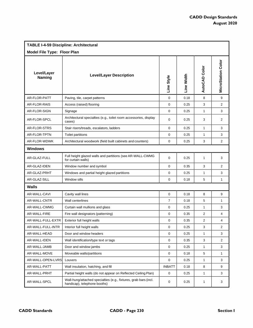
CADD Standards CADD - Page 230 Section I
CADD Design Standards
August 2020
TABLE I-4-59 Discipline: Architectural
Model File Type: Floor Plan
Level/Layer
Naming
Level/Layer Description
Lin
e S
tyle
Lin
e W
idth
Au
toC
AD
Co
lor
Mic
roS
tati
on
Co
lor
AR-FLOR-PATT Paving, tile, carpet patterns 0 0.18 8 9
AR-FLOR-RAIS Access (raised) flooring 0 0.25 3 2
AR-FLOR-SIGN Signage 0 0.25 1 3
AR-FLOR-SPCL Architectural specialties (e.g., toilet room accessories, display cases)
0
0.25
3
2
AR-FLOR-STRS Stair risers/treads, escalators, ladders 0 0.25 1 3
AR-FLOR-TPTN Toilet partitions 0 0.25 1 3
AR-FLOR-WDWK Architectural woodwork (field built cabinets and counters) 0 0.25 3 2
Windows
AR-GLAZ-FULL Full height glazed walls and partitions (see AR-WALL-CWMG for curtain walls)
0
0.25
1
3
AR-GLAZ-IDEN Window number and symbol 0 0.35 3 2
AR-GLAZ-PRHT Windows and partial height glazed partitions 0 0.25 1 3
AR-GLAZ-SILL Window sills 0 0.18 5 1
Walls
AR-WALL-CAVI Cavity wall lines 0 0.18 8 9
AR-WALL-CNTR Wall centerlines 7 0.18 5 1
AR-WALL-CWMG Curtain wall mullions and glass 0 0.25 1 3
AR-WALL-FIRE Fire wall designators (patterning) 0 0.35 2 4
AR-WALL-FULL-EXTR Exterior full height walls 0 0.35 2 4
AR-WALL-FULL-INTR Interior full height walls 0 0.25 3 2
AR-WALL-HEAD Door and window headers 0 0.25 1 3
AR-WALL-IDEN Wall identification/type text or tags 0 0.35 3 2
AR-WALL-JAMB Door and window jambs 0 0.25 1 3
AR-WALL-MOVE Moveable walls/partitions 0 0.18 5 1
AR-WALL-OPEN-LVRS Louvers 0 0.25 1 3
AR-WALL-PATT Wall insulation, hatching, and fill INBATT 0.18 8 9
AR-WALL-PRHT Partial height walls (do not appear on Reflected Ceiling Plan) 0 0.25 1 3
AR-WALL-SPCL Wall-hung/attached specialties (e.g., fixtures, grab bars (incl. handicap), telephone booths)
0
0.25
1
3
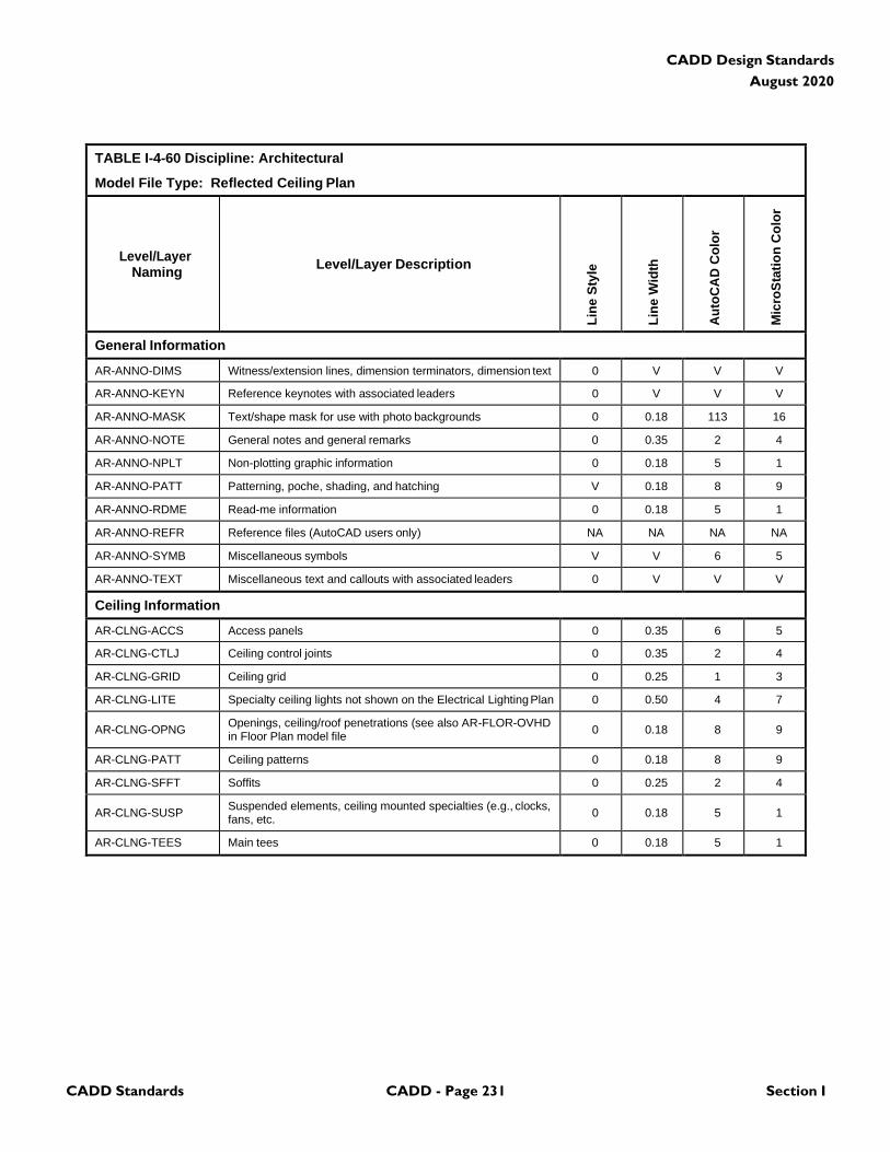
CADD Standards CADD - Page 231 Section I
CADD Design Standards
August 2020
TABLE I-4-60 Discipline: Architectural
Model File Type: Reflected Ceiling Plan
Level/Layer
Naming
Level/Layer Description
Lin
e S
tyle
Lin
e W
idth
Au
toC
AD
Co
lor
Mic
roS
tati
on
Co
lor
General Information
AR-ANNO-DIMS Witness/extension lines, dimension terminators, dimension text 0 V V V
AR-ANNO-KEYN Reference keynotes with associated leaders 0 V V V
AR-ANNO-MASK Text/shape mask for use with photo backgrounds 0 0.18 113 16
AR-ANNO-NOTE General notes and general remarks 0 0.35 2 4
AR-ANNO-NPLT Non-plotting graphic information 0 0.18 5 1
AR-ANNO-PATT Patterning, poche, shading, and hatching V 0.18 8 9
AR-ANNO-RDME Read-me information 0 0.18 5 1
AR-ANNO-REFR Reference files (AutoCAD users only) NA NA NA NA
AR-ANNO-SYMB Miscellaneous symbols V V 6 5
AR-ANNO-TEXT Miscellaneous text and callouts with associated leaders 0 V V V
Ceiling Information
AR-CLNG-ACCS Access panels 0 0.35 6 5
AR-CLNG-CTLJ Ceiling control joints 0 0.35 2 4
AR-CLNG-GRID Ceiling grid 0 0.25 1 3
AR-CLNG-LITE Specialty ceiling lights not shown on the Electrical Lighting Plan 0 0.50 4 7
AR-CLNG-OPNG Openings, ceiling/roof penetrations (see also AR-FLOR-OVHD in Floor Plan model file
0
0.18
8
9
AR-CLNG-PATT Ceiling patterns 0 0.18 8 9
AR-CLNG-SFFT Soffits 0 0.25 2 4
AR-CLNG-SUSP Suspended elements, ceiling mounted specialties (e.g., clocks, fans, etc.
0
0.18
5
1
AR-CLNG-TEES Main tees 0 0.18 5 1
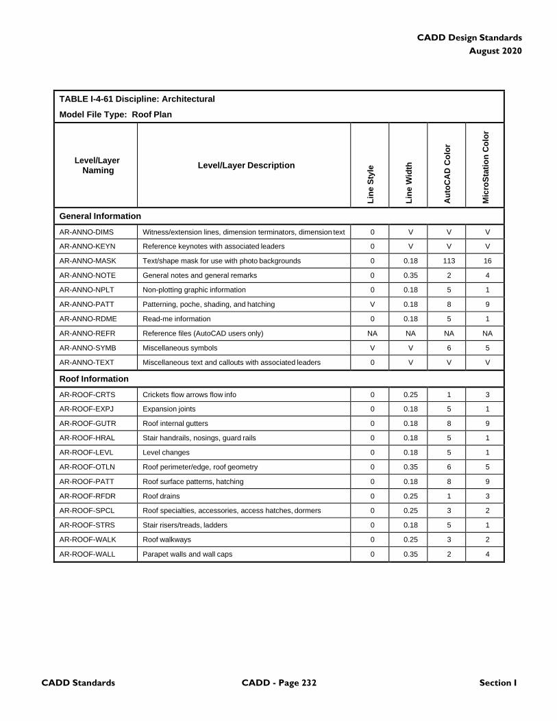
CADD Standards CADD - Page 232 Section I
CADD Design Standards
August 2020
TABLE I-4-61 Discipline: Architectural
Model File Type: Roof Plan
Level/Layer
Naming
Level/Layer Description
Lin
e S
tyle
Lin
e W
idth
Au
toC
AD
Co
lor
Mic
roS
tati
on
Co
lor
General Information
AR-ANNO-DIMS Witness/extension lines, dimension terminators, dimension text 0 V V V
AR-ANNO-KEYN Reference keynotes with associated leaders 0 V V V
AR-ANNO-MASK Text/shape mask for use with photo backgrounds 0 0.18 113 16
AR-ANNO-NOTE General notes and general remarks 0 0.35 2 4
AR-ANNO-NPLT Non-plotting graphic information 0 0.18 5 1
AR-ANNO-PATT Patterning, poche, shading, and hatching V 0.18 8 9
AR-ANNO-RDME Read-me information 0 0.18 5 1
AR-ANNO-REFR Reference files (AutoCAD users only) NA NA NA NA
AR-ANNO-SYMB Miscellaneous symbols V V 6 5
AR-ANNO-TEXT Miscellaneous text and callouts with associated leaders 0 V V V
Roof Information
AR-ROOF-CRTS Crickets flow arrows flow info 0 0.25 1 3
AR-ROOF-EXPJ Expansion joints 0 0.18 5 1
AR-ROOF-GUTR Roof internal gutters 0 0.18 8 9
AR-ROOF-HRAL Stair handrails, nosings, guard rails 0 0.18 5 1
AR-ROOF-LEVL Level changes 0 0.18 5 1
AR-ROOF-OTLN Roof perimeter/edge, roof geometry 0 0.35 6 5
AR-ROOF-PATT Roof surface patterns, hatching 0 0.18 8 9
AR-ROOF-RFDR Roof drains 0 0.25 1 3
AR-ROOF-SPCL Roof specialties, accessories, access hatches, dormers 0 0.25 3 2
AR-ROOF-STRS Stair risers/treads, ladders 0 0.18 5 1
AR-ROOF-WALK Roof walkways 0 0.25 3 2
AR-ROOF-WALL Parapet walls and wall caps 0 0.35 2 4
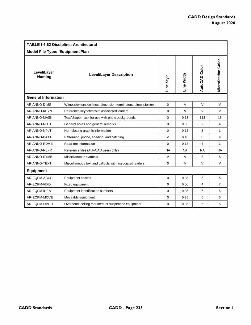
CADD Standards CADD - Page 233 Section I
CADD Design Standards
August 2020
TABLE I-4-62 Discipline: Architectural
Model File Type: Equipment Plan
Level/Layer
Naming
Level/Layer Description
Lin
e S
tyle
Lin
e W
idth
Au
toC
AD
Co
lor
Mic
roS
tati
on
Co
lor
General Information
AR-ANNO-DIMS Witness/extension lines, dimension terminators, dimension text 0 V V V
AR-ANNO-KEYN Reference keynotes with associated leaders 0 V V V
AR-ANNO-MASK Text/shape mask for use with photo backgrounds 0 0.18 113 16
AR-ANNO-NOTE General notes and general remarks 0 0.35 2 4
AR-ANNO-NPLT Non-plotting graphic information 0 0.18 5 1
AR-ANNO-PATT Patterning, poche, shading, and hatching V 0.18 8 9
AR-ANNO-RDME Read-me information 0 0.18 5 1
AR-ANNO-REFR Reference files (AutoCAD users only) NA NA NA NA
AR-ANNO-SYMB Miscellaneous symbols V V 6 5
AR-ANNO-TEXT Miscellaneous text and callouts with associated leaders 0 V V V
Equipment
AR-EQPM-ACCS Equipment access 0 0.35 6 5
AR-EQPM-FIXD Fixed equipment 0 0.50 4 7
AR-EQPM-IDEN Equipment identification numbers 0 0.35 6 5
AR-EQPM-MOVE Moveable equipment 0 0.35 6 5
AR-EQPM-OVHD Overhead, ceiling mounted, or suspended equipment 0 0.35 6 5
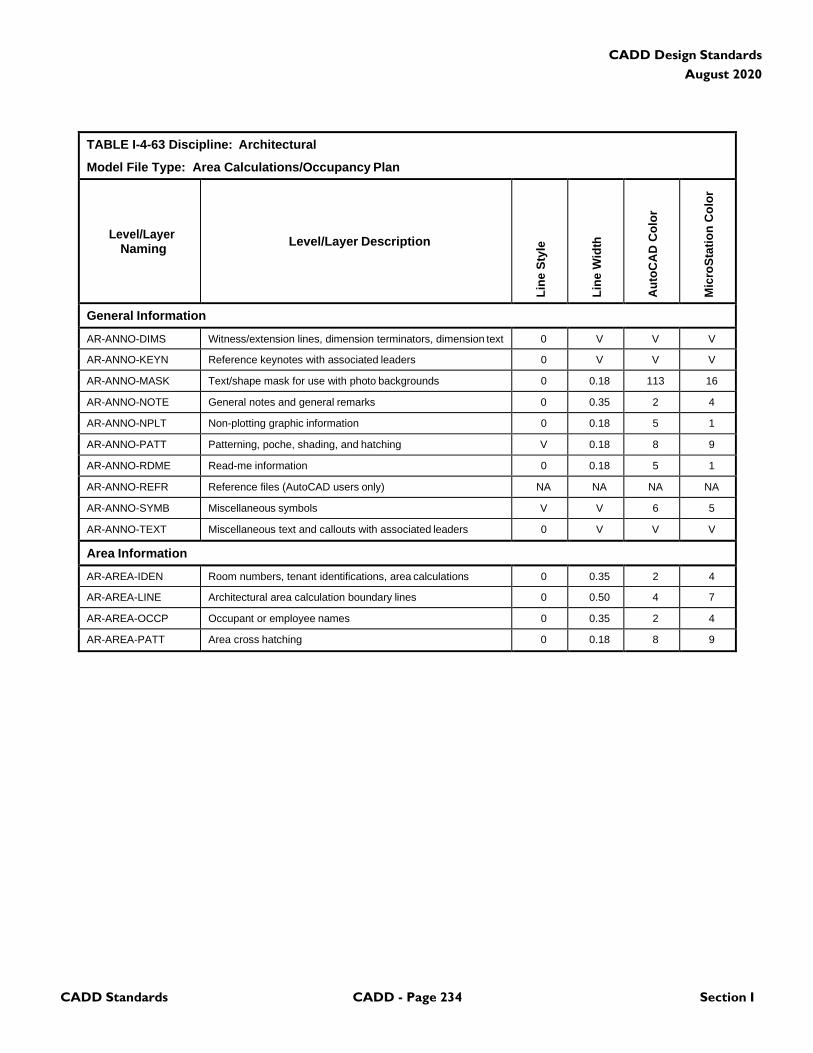
CADD Standards CADD - Page 234 Section I
CADD Design Standards
August 2020
TABLE I-4-63 Discipline: Architectural
Model File Type: Area Calculations/Occupancy Plan
Level/Layer
Naming
Level/Layer Description
Lin
e S
tyle
Lin
e W
idth
Au
toC
AD
Co
lor
Mic
roS
tati
on
Co
lor
General Information
AR-ANNO-DIMS Witness/extension lines, dimension terminators, dimension text 0 V V V
AR-ANNO-KEYN Reference keynotes with associated leaders 0 V V V
AR-ANNO-MASK Text/shape mask for use with photo backgrounds 0 0.18 113 16
AR-ANNO-NOTE General notes and general remarks 0 0.35 2 4
AR-ANNO-NPLT Non-plotting graphic information 0 0.18 5 1
AR-ANNO-PATT Patterning, poche, shading, and hatching V 0.18 8 9
AR-ANNO-RDME Read-me information 0 0.18 5 1
AR-ANNO-REFR Reference files (AutoCAD users only) NA NA NA NA
AR-ANNO-SYMB Miscellaneous symbols V V 6 5
AR-ANNO-TEXT Miscellaneous text and callouts with associated leaders 0 V V V
Area Information
AR-AREA-IDEN Room numbers, tenant identifications, area calculations 0 0.35 2 4
AR-AREA-LINE Architectural area calculation boundary lines 0 0.50 4 7
AR-AREA-OCCP Occupant or employee names 0 0.35 2 4
AR-AREA-PATT Area cross hatching 0 0.18 8 9
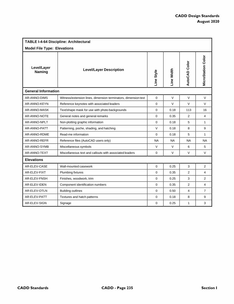
CADD Standards CADD - Page 235 Section I
CADD Design Standards
August 2020
TABLE I-4-64 Discipline: Architectural
Model File Type: Elevations
Level/Layer
Naming
Level/Layer Description
Lin
e S
tyle
Lin
e W
idth
Au
toC
AD
Co
lor
Mic
roS
tati
on
Co
lor
General Information
AR-ANNO-DIMS Witness/extension lines, dimension terminators, dimension text 0 V V V
AR-ANNO-KEYN Reference keynotes with associated leaders 0 V V V
AR-ANNO-MASK Text/shape mask for use with photo backgrounds 0 0.18 113 16
AR-ANNO-NOTE General notes and general remarks 0 0.35 2 4
AR-ANNO-NPLT Non-plotting graphic information 0 0.18 5 1
AR-ANNO-PATT Patterning, poche, shading, and hatching V 0.18 8 9
AR-ANNO-RDME Read-me information 0 0.18 5 1
AR-ANNO-REFR Reference files (AutoCAD users only) NA NA NA NA
AR-ANNO-SYMB Miscellaneous symbols V V 6 5
AR-ANNO-TEXT Miscellaneous text and callouts with associated leaders 0 V V V
Elevations
AR-ELEV-CASE Wall-mounted casework 0 0.25 3 2
AR-ELEV-FIXT Plumbing fixtures 0 0.35 2 4
AR-ELEV-FNSH Finishes, woodwork, trim 0 0.25 3 2
AR-ELEV-IDEN Component identification numbers 0 0.35 2 4
AR-ELEV-OTLN Building outlines 0 0.50 4 7
AR-ELEV-PATT Textures and hatch patterns 0 0.18 8 9
AR-ELEV-SIGN Signage 0 0.25 1 3
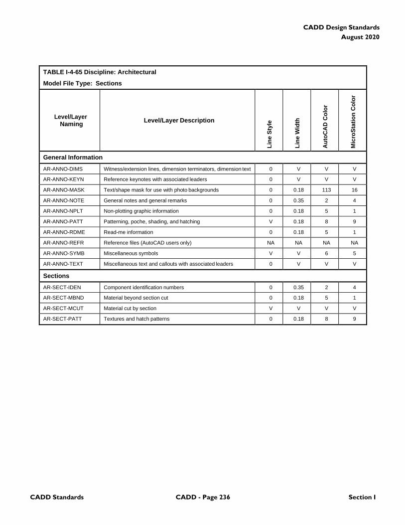
CADD Standards CADD - Page 236 Section I
CADD Design Standards
August 2020
TABLE I-4-65 Discipline: Architectural
Model File Type: Sections
Level/Layer
Naming
Level/Layer Description
Lin
e S
tyle
Lin
e W
idth
Au
toC
AD
Co
lor
Mic
roS
tati
on
Co
lor
General Information
AR-ANNO-DIMS Witness/extension lines, dimension terminators, dimension text 0 V V V
AR-ANNO-KEYN Reference keynotes with associated leaders 0 V V V
AR-ANNO-MASK Text/shape mask for use with photo backgrounds 0 0.18 113 16
AR-ANNO-NOTE General notes and general remarks 0 0.35 2 4
AR-ANNO-NPLT Non-plotting graphic information 0 0.18 5 1
AR-ANNO-PATT Patterning, poche, shading, and hatching V 0.18 8 9
AR-ANNO-RDME Read-me information 0 0.18 5 1
AR-ANNO-REFR Reference files (AutoCAD users only) NA NA NA NA
AR-ANNO-SYMB Miscellaneous symbols V V 6 5
AR-ANNO-TEXT Miscellaneous text and callouts with associated leaders 0 V V V
Sections
AR-SECT-IDEN Component identification numbers 0 0.35 2 4
AR-SECT-MBND Material beyond section cut 0 0.18 5 1
AR-SECT-MCUT Material cut by section V V V V
AR-SECT-PATT Textures and hatch patterns 0 0.18 8 9
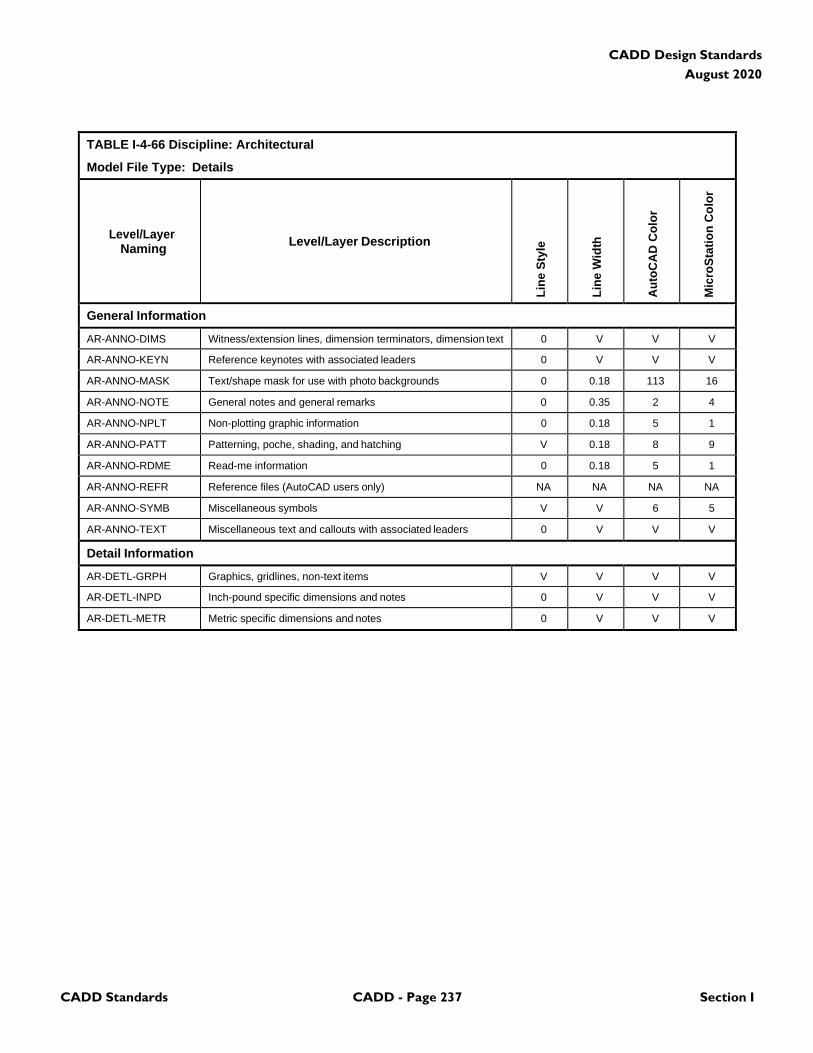
CADD Standards CADD - Page 237 Section I
CADD Design Standards
August 2020
TABLE I-4-66 Discipline: Architectural
Model File Type: Details
Level/Layer
Naming
Level/Layer Description
Lin
e S
tyle
Lin
e W
idth
Au
toC
AD
Co
lor
Mic
roS
tati
on
Co
lor
General Information
AR-ANNO-DIMS Witness/extension lines, dimension terminators, dimension text 0 V V V
AR-ANNO-KEYN Reference keynotes with associated leaders 0 V V V
AR-ANNO-MASK Text/shape mask for use with photo backgrounds 0 0.18 113 16
AR-ANNO-NOTE General notes and general remarks 0 0.35 2 4
AR-ANNO-NPLT Non-plotting graphic information 0 0.18 5 1
AR-ANNO-PATT Patterning, poche, shading, and hatching V 0.18 8 9
AR-ANNO-RDME Read-me information 0 0.18 5 1
AR-ANNO-REFR Reference files (AutoCAD users only) NA NA NA NA
AR-ANNO-SYMB Miscellaneous symbols V V 6 5
AR-ANNO-TEXT Miscellaneous text and callouts with associated leaders 0 V V V
Detail Information
AR-DETL-GRPH Graphics, gridlines, non-text items V V V V
AR-DETL-INPD Inch-pound specific dimensions and notes 0 V V V
AR-DETL-METR Metric specific dimensions and notes 0 V V V

CADD Standards CADD - Page 238 Section I
CADD Design Standards
August 2020
4.13 Interiors
TABLE I-4-67 Discipline: Interiors
Model File Type: Demolition Plan
Level/Layer
Naming
Level/Layer Description
Lin
e S
tyle
Lin
e W
idth
Au
toC
AD
Co
lor
Mic
roS
tati
on
Co
lor
General Information
IN-ANNO-DIMS Witness extension lines, dimensions arrowheads and text 0 V V V
IN-ANNO-KEYN Keynote with associated leaderlines and arrowheads 0 V V V
IN-ANNO-NPLT Construction lines, reference targets, area calculations V 0 5 1
IN-ANNO-PATT Miscellaneous patterning 0 0 8 9
IN-ANNO-NOTE General note and general remarks 0 2 2 4
IN-ANNO-SYMB Reference bubbles, matchlines, breaklines V 2 6 5
IN-ANNO-TEXT Detail title text, leaderlines, arrowheads, notes 0 V V V
IN-STAT-DEMO Demolition 2 2 6 5
IN-STAT-EXST Existing to remain 0 1 3 2
IN-STAT-MOVE Items to be moved 5 2 6 5
IN-STAT-NICN Not in contract 3 0 8 9
IN-STAT-PHS# Phase numbers (# = 1-9) 0 2 2 4
IN-STAT-RELO Relocated items 2 0 5 1
IN-STAT-TEMP Temporary work 4 3 4 7
IN-DEMO-HAZW Hazardous waste 0 2 6 5
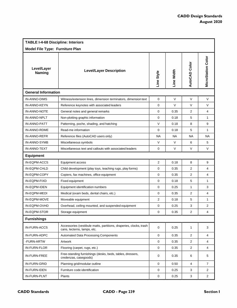
CADD Standards CADD - Page 239 Section I
CADD Design Standards
August 2020
TABLE I-4-68 Discipline: Interiors
Model File Type: Furniture Plan
Level/Layer
Naming
Level/Layer Description
Lin
e S
tyle
Lin
e W
idth
Au
toC
AD
Co
lor
Mic
roS
tati
on
Co
lor
General Information
IN-ANNO-DIMS Witness/extension lines, dimension terminators, dimension text 0 V V V
IN-ANNO-KEYN Reference keynotes with associated leaders 0 V V V
IN-ANNO-NOTE General notes and general remarks 0 0.35 2 4
IN-ANNO-NPLT Non-plotting graphic information 0 0.18 5 1
IN-ANNO-PATT Patterning, poche, shading, and hatching V 0.18 8 9
IN-ANNO-RDME Read-me information 0 0.18 5 1
IN-ANNO-REFR Reference files (AutoCAD users only) NA NA NA NA
IN-ANNO-SYMB Miscellaneous symbols V V 6 5
IN-ANNO-TEXT Miscellaneous text and callouts with associated leaders 0 V V V
Equipment
IN-EQPM-ACCS Equipment access 2 0.18 8 9
IN-EQPM-CHLD Child development (play toys, teaching rugs, play forms) 0 0.35 2 4
IN-EQPM-COPY Copiers, fax machines, office equipment 0 0.35 2 4
IN-EQPM-FIXD Fixed equipment 0 0.18 5 1
IN-EQPM-IDEN Equipment identification numbers 0 0.25 1 3
IN-EQPM-MEDI Medical (exam beds, dental chairs, etc.) 0 0.35 2 4
IN-EQPM-MOVE Moveable equipment 2 0.18 5 1
IN-EQPM-OVHD Overhead, ceiling mounted, and suspended equipment 0 0.25 3 2
IN-EQPM-STOR Storage equipment 0 0.35 2 4
Furnishings
IN-FURN-ACCS Accessories (vestibule matts, partitions, draperies, clocks, trash cans, lecterns, lamps, etc.
0
0.25
1
3
IN-FURN-ADPC Automated Data Processing Components 0 0.35 2 4
-FURN-ARTW Artwork 0 0.35 2 4
IN-FURN-FLOR Flooring (carpet, rugs, etc.) 0 0.35 2 4
IN-FURN-FREE Free-standing furnishings (desks, beds, tables, dressers, credenzas, casegoods)
0
0.35
6
5
IN-FURN-GRID Planning grid/modular outline 0 0.50 4 7
IN-FURN-IDEN Furniture code identification 0 0.25 3 2
IN-FURN-PLNT Plants 0 0.25 3 2
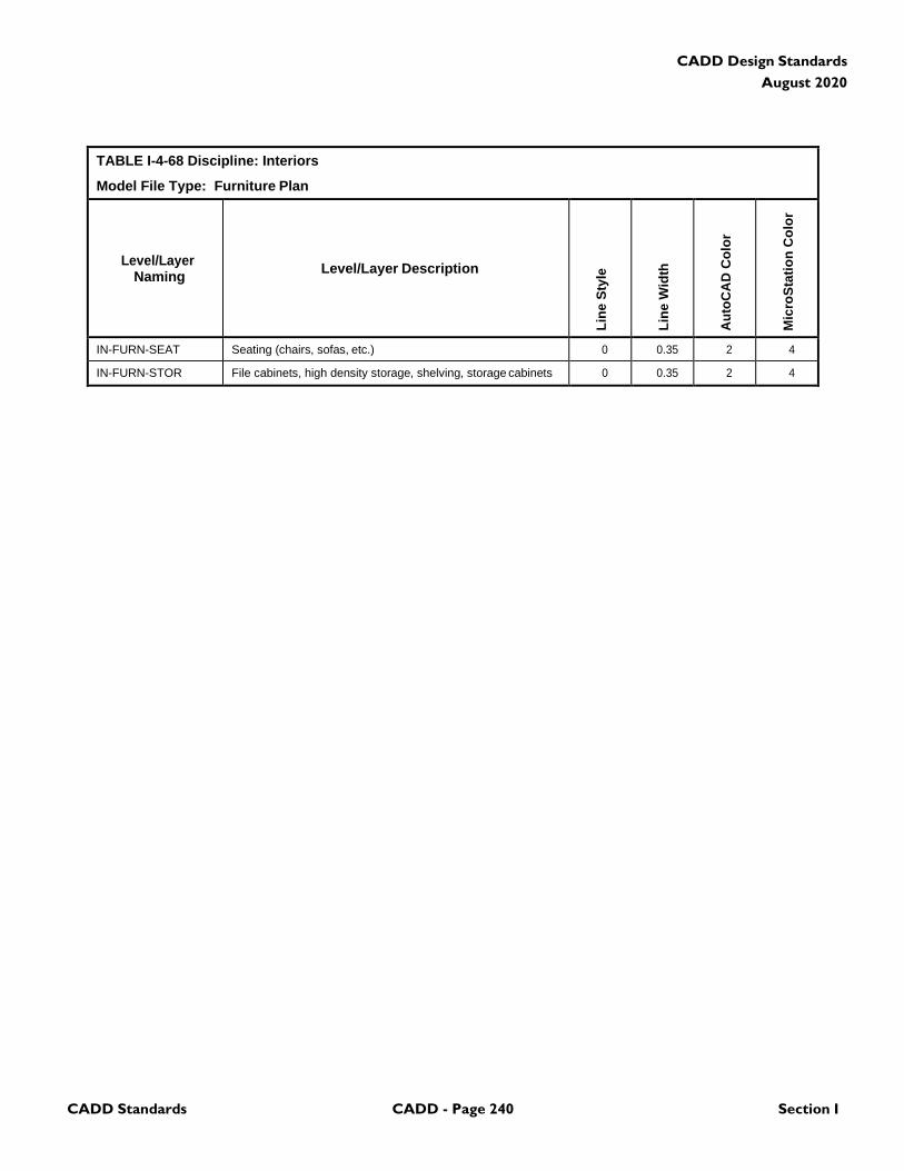
CADD Standards CADD - Page 240 Section I
CADD Design Standards
August 2020
TABLE I-4-68 Discipline: Interiors
Model File Type: Furniture Plan
Level/Layer
Naming
Level/Layer Description
Lin
e S
tyle
Lin
e W
idth
Au
toC
AD
Co
lor
Mic
roS
tati
on
Co
lor
IN-FURN-SEAT Seating (chairs, sofas, etc.) 0 0.35 2 4
IN-FURN-STOR File cabinets, high density storage, shelving, storage cabinets 0 0.35 2 4
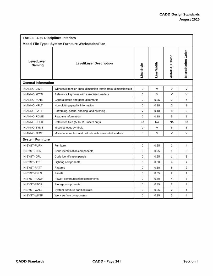
CADD Standards CADD - Page 241 Section I
CADD Design Standards
August 2020
TABLE I-4-69 Discipline: Interiors
Model File Type: System Furniture Workstation Plan
Level/Layer
Naming
Level/Layer Description
Lin
e S
tyle
Lin
e W
idth
Au
toC
AD
Co
lor
Mic
roS
tati
on
Co
lor
General Information
IN-ANNO-DIMS Witness/extension lines, dimension terminators, dimension text 0 V V V
IN-ANNO-KEYN Reference keynotes with associated leaders 0 V V V
IN-ANNO-NOTE General notes and general remarks 0 0.35 2 4
IN-ANNO-NPLT Non-plotting graphic information 0 0.18 5 1
IN-ANNO-PATT Patterning, poche, shading, and hatching V 0.18 8 9
IN-ANNO-RDME Read-me information 0 0.18 5 1
IN-ANNO-REFR Reference files (AutoCAD users only) NA NA NA NA
IN-ANNO-SYMB Miscellaneous symbols V V 6 5
IN-ANNO-TEXT Miscellaneous text and callouts with associated leaders 0 V V V
System Furniture
IN-SYST-FURN Furniture 0 0.35 2 4
IN-SYST-IDEN Code identification components 0 0.25 1 3
IN-SYST-IDPL Code identification panels 0 0.25 1 3
IN-SYST-LITE Lighting components 0 0.50 4 7
IN-SYST-PATT Patterns 0 0.18 8 9
IN-SYST-PNLS Panels 0 0.35 2 4
IN-SYST-POWR Power, communication components 0 0.50 4 7
IN-SYST-STOR Storage components 0 0.35 2 4
IN-SYST-WALL System furniture partition walls 0 0.35 2 4
IN-SYST-WKSF Work surface components 0 0.35 2 4
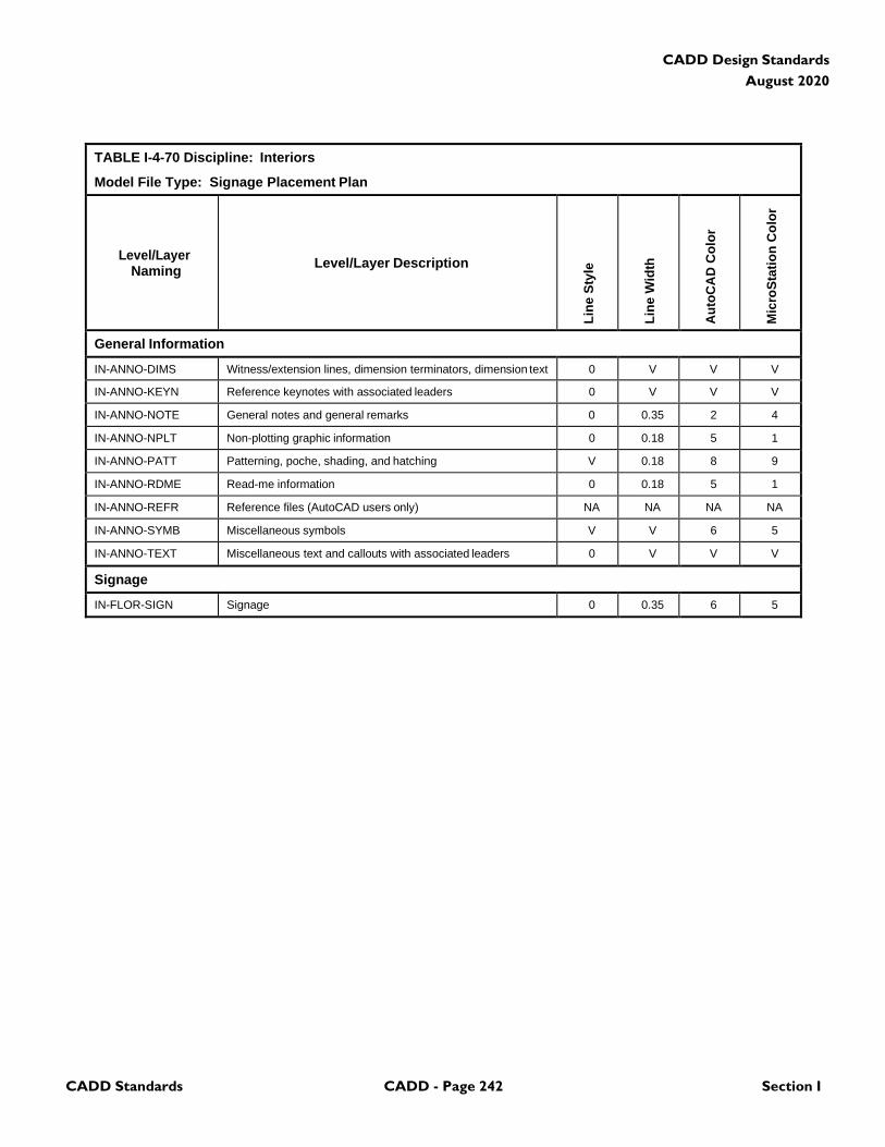
CADD Standards CADD - Page 242 Section I
CADD Design Standards
August 2020
TABLE I-4-70 Discipline: Interiors
Model File Type: Signage Placement Plan
Level/Layer
Naming
Level/Layer Description
Lin
e S
tyle
Lin
e W
idth
Au
toC
AD
Co
lor
Mic
roS
tati
on
Co
lor
General Information
IN-ANNO-DIMS Witness/extension lines, dimension terminators, dimension text 0 V V V
IN-ANNO-KEYN Reference keynotes with associated leaders 0 V V V
IN-ANNO-NOTE General notes and general remarks 0 0.35 2 4
IN-ANNO-NPLT Non-plotting graphic information 0 0.18 5 1
IN-ANNO-PATT Patterning, poche, shading, and hatching V 0.18 8 9
IN-ANNO-RDME Read-me information 0 0.18 5 1
IN-ANNO-REFR Reference files (AutoCAD users only) NA NA NA NA
IN-ANNO-SYMB Miscellaneous symbols V V 6 5
IN-ANNO-TEXT Miscellaneous text and callouts with associated leaders 0 V V V
Signage
IN-FLOR-SIGN Signage 0 0.35 6 5
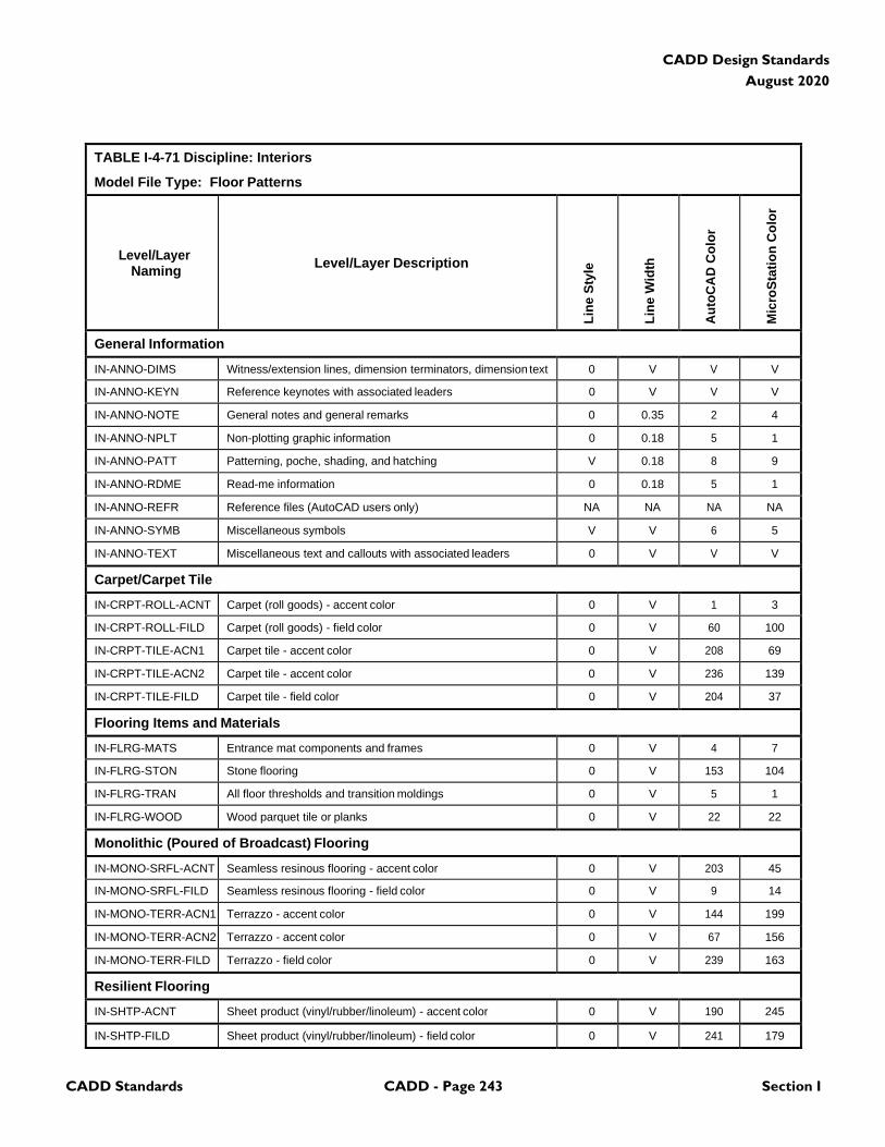
CADD Standards CADD - Page 243 Section I
CADD Design Standards
August 2020
TABLE I-4-71 Discipline: Interiors
Model File Type: Floor Patterns
Level/Layer
Naming
Level/Layer Description
Lin
e S
tyle
Lin
e W
idth
Au
toC
AD
Co
lor
Mic
roS
tati
on
Co
lor
General Information
IN-ANNO-DIMS Witness/extension lines, dimension terminators, dimension text 0 V V V
IN-ANNO-KEYN Reference keynotes with associated leaders 0 V V V
IN-ANNO-NOTE General notes and general remarks 0 0.35 2 4
IN-ANNO-NPLT Non-plotting graphic information 0 0.18 5 1
IN-ANNO-PATT Patterning, poche, shading, and hatching V 0.18 8 9
IN-ANNO-RDME Read-me information 0 0.18 5 1
IN-ANNO-REFR Reference files (AutoCAD users only) NA NA NA NA
IN-ANNO-SYMB Miscellaneous symbols V V 6 5
IN-ANNO-TEXT Miscellaneous text and callouts with associated leaders 0 V V V
Carpet/Carpet Tile
IN-CRPT-ROLL-ACNT Carpet (roll goods) - accent color 0 V 1 3
IN-CRPT-ROLL-FILD Carpet (roll goods) - field color 0 V 60 100
IN-CRPT-TILE-ACN1 Carpet tile - accent color 0 V 208 69
IN-CRPT-TILE-ACN2 Carpet tile - accent color 0 V 236 139
IN-CRPT-TILE-FILD Carpet tile - field color 0 V 204 37
Flooring Items and Materials
IN-FLRG-MATS Entrance mat components and frames 0 V 4 7
IN-FLRG-STON Stone flooring 0 V 153 104
IN-FLRG-TRAN All floor thresholds and transition moldings 0 V 5 1
IN-FLRG-WOOD Wood parquet tile or planks 0 V 22 22
Monolithic (Poured of Broadcast) Flooring
IN-MONO-SRFL-ACNT Seamless resinous flooring - accent color 0 V 203 45
IN-MONO-SRFL-FILD Seamless resinous flooring - field color 0 V 9 14
IN-MONO-TERR-ACN1 Terrazzo - accent color 0 V 144 199
IN-MONO-TERR-ACN2 Terrazzo - accent color 0 V 67 156
IN-MONO-TERR-FILD Terrazzo - field color 0 V 239 163
Resilient Flooring
IN-SHTP-ACNT Sheet product (vinyl/rubber/linoleum) - accent color 0 V 190 245
IN-SHTP-FILD Sheet product (vinyl/rubber/linoleum) - field color 0 V 241 179
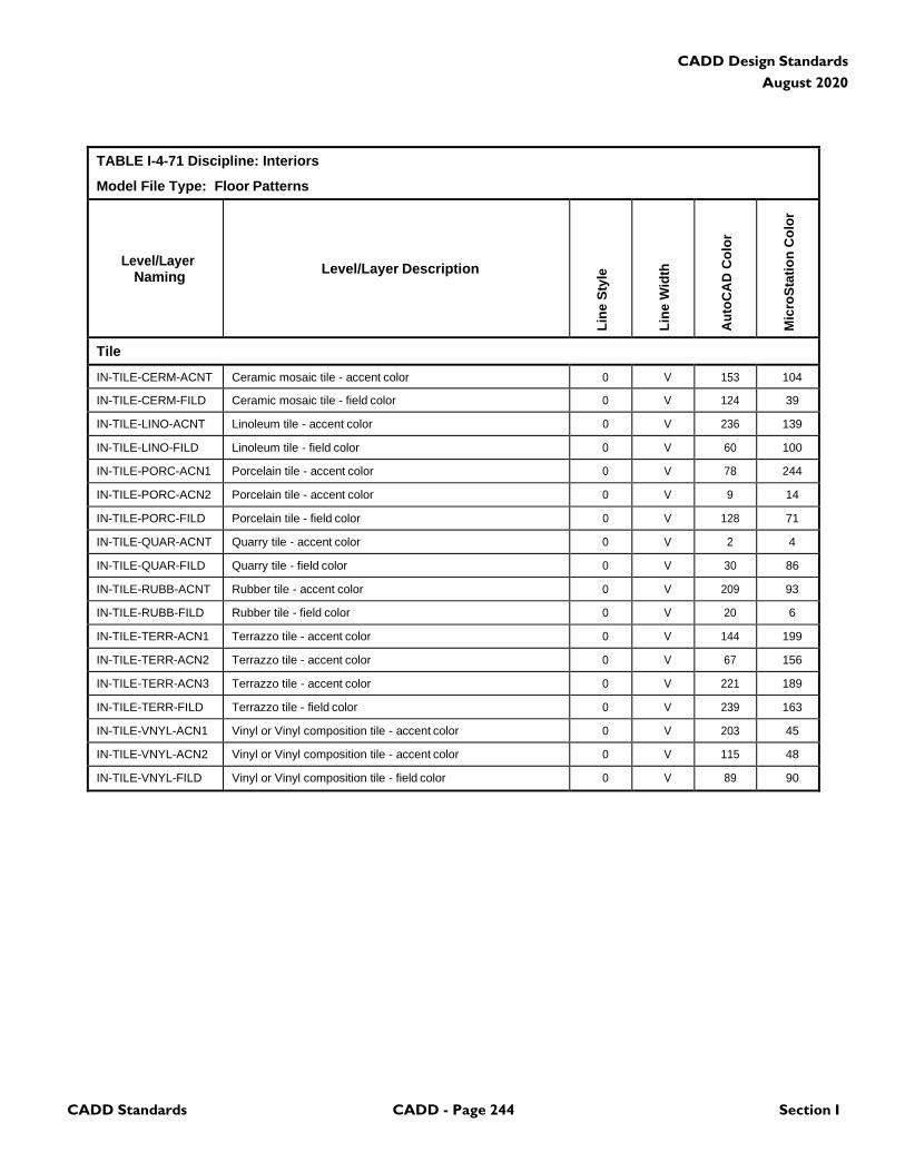
CADD Standards CADD - Page 244 Section I
CADD Design Standards
August 2020
TABLE I-4-71 Discipline: Interiors
Model File Type: Floor Patterns
Level/Layer
Naming
Level/Layer Description
Lin
e S
tyle
Lin
e W
idth
Au
toC
AD
Co
lor
Mic
roS
tati
on
Co
lor
Tile
IN-TILE-CERM-ACNT Ceramic mosaic tile - accent color 0 V 153 104
IN-TILE-CERM-FILD Ceramic mosaic tile - field color 0 V 124 39
IN-TILE-LINO-ACNT Linoleum tile - accent color 0 V 236 139
IN-TILE-LINO-FILD Linoleum tile - field color 0 V 60 100
IN-TILE-PORC-ACN1 Porcelain tile - accent color 0 V 78 244
IN-TILE-PORC-ACN2 Porcelain tile - accent color 0 V 9 14
IN-TILE-PORC-FILD Porcelain tile - field color 0 V 128 71
IN-TILE-QUAR-ACNT Quarry tile - accent color 0 V 2 4
IN-TILE-QUAR-FILD Quarry tile - field color 0 V 30 86
IN-TILE-RUBB-ACNT Rubber tile - accent color 0 V 209 93
IN-TILE-RUBB-FILD Rubber tile - field color 0 V 20 6
IN-TILE-TERR-ACN1 Terrazzo tile - accent color 0 V 144 199
IN-TILE-TERR-ACN2 Terrazzo tile - accent color 0 V 67 156
IN-TILE-TERR-ACN3 Terrazzo tile - accent color 0 V 221 189
IN-TILE-TERR-FILD Terrazzo tile - field color 0 V 239 163
IN-TILE-VNYL-ACN1 Vinyl or Vinyl composition tile - accent color 0 V 203 45
IN-TILE-VNYL-ACN2 Vinyl or Vinyl composition tile - accent color 0 V 115 48
IN-TILE-VNYL-FILD Vinyl or Vinyl composition tile - field color 0 V 89 90
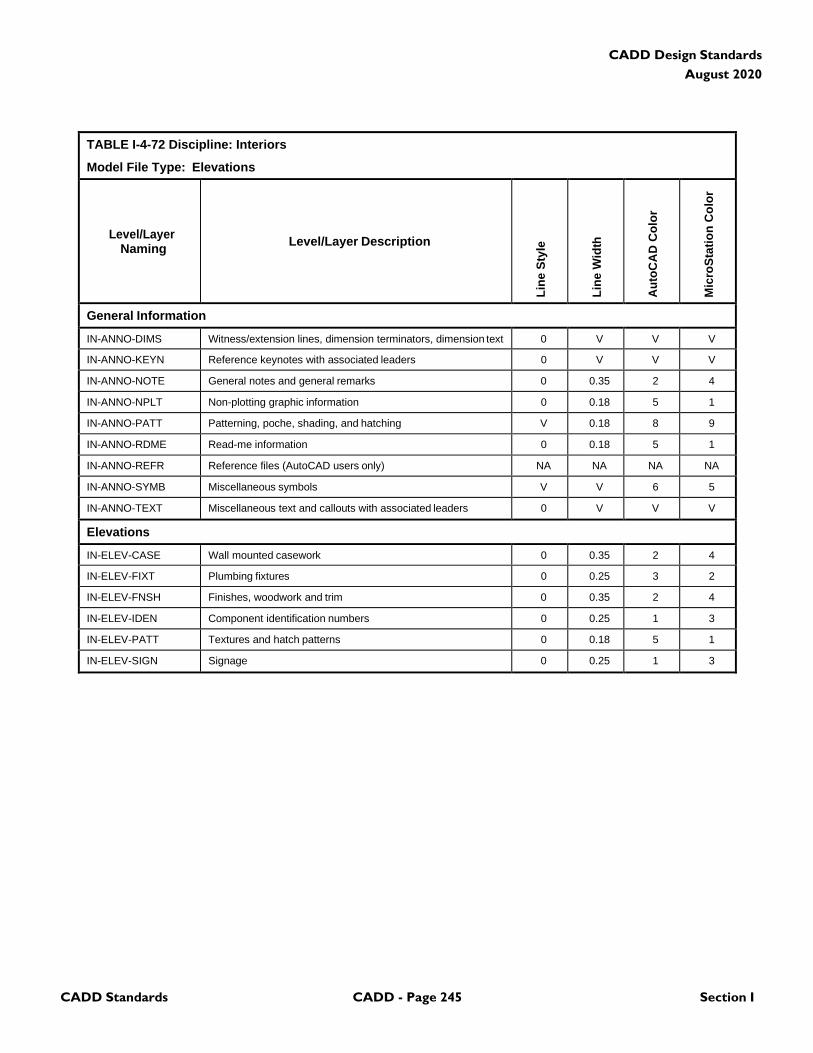
CADD Standards CADD - Page 245 Section I
CADD Design Standards
August 2020
TABLE I-4-72 Discipline: Interiors
Model File Type: Elevations
Level/Layer
Naming
Level/Layer Description
Lin
e S
tyle
Lin
e W
idth
Au
toC
AD
Co
lor
Mic
roS
tati
on
Co
lor
General Information
IN-ANNO-DIMS Witness/extension lines, dimension terminators, dimension text 0 V V V
IN-ANNO-KEYN Reference keynotes with associated leaders 0 V V V
IN-ANNO-NOTE General notes and general remarks 0 0.35 2 4
IN-ANNO-NPLT Non-plotting graphic information 0 0.18 5 1
IN-ANNO-PATT Patterning, poche, shading, and hatching V 0.18 8 9
IN-ANNO-RDME Read-me information 0 0.18 5 1
IN-ANNO-REFR Reference files (AutoCAD users only) NA NA NA NA
IN-ANNO-SYMB Miscellaneous symbols V V 6 5
IN-ANNO-TEXT Miscellaneous text and callouts with associated leaders 0 V V V
Elevations
IN-ELEV-CASE Wall mounted casework 0 0.35 2 4
IN-ELEV-FIXT Plumbing fixtures 0 0.25 3 2
IN-ELEV-FNSH Finishes, woodwork and trim 0 0.35 2 4
IN-ELEV-IDEN Component identification numbers 0 0.25 1 3
IN-ELEV-PATT Textures and hatch patterns 0 0.18 5 1
IN-ELEV-SIGN Signage 0 0.25 1 3
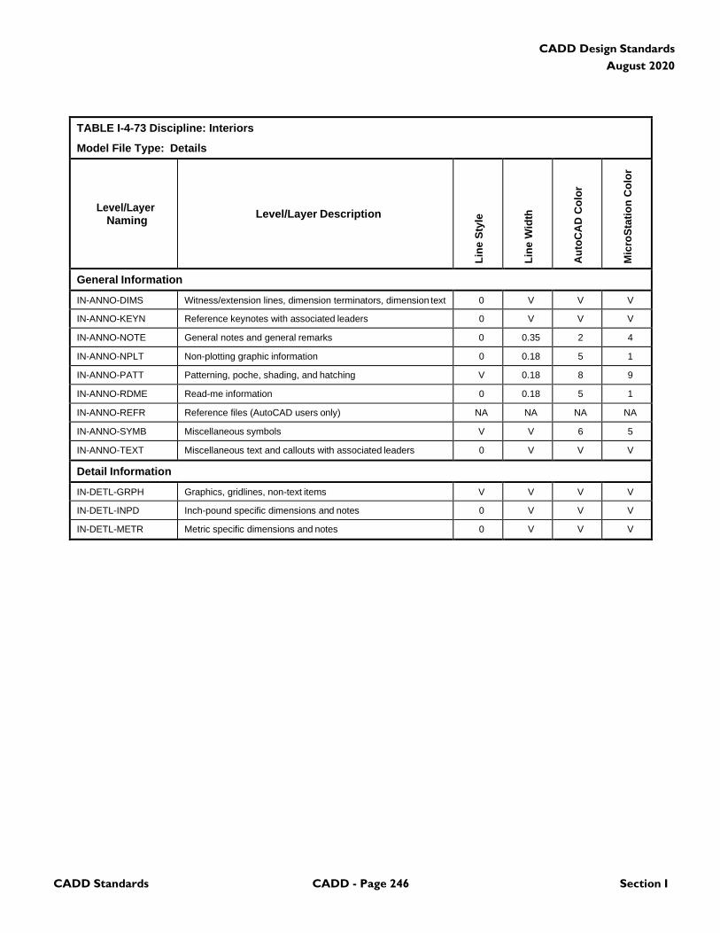
CADD Standards CADD - Page 246 Section I
CADD Design Standards
August 2020
TABLE I-4-73 Discipline: Interiors
Model File Type: Details
Level/Layer
Naming
Level/Layer Description
Lin
e S
tyle
Lin
e W
idth
Au
toC
AD
Co
lor
Mic
roS
tati
on
Co
lor
General Information
IN-ANNO-DIMS Witness/extension lines, dimension terminators, dimension text 0 V V V
IN-ANNO-KEYN Reference keynotes with associated leaders 0 V V V
IN-ANNO-NOTE General notes and general remarks 0 0.35 2 4
IN-ANNO-NPLT Non-plotting graphic information 0 0.18 5 1
IN-ANNO-PATT Patterning, poche, shading, and hatching V 0.18 8 9
IN-ANNO-RDME Read-me information 0 0.18 5 1
IN-ANNO-REFR Reference files (AutoCAD users only) NA NA NA NA
IN-ANNO-SYMB Miscellaneous symbols V V 6 5
IN-ANNO-TEXT Miscellaneous text and callouts with associated leaders 0 V V V
Detail Information
IN-DETL-GRPH Graphics, gridlines, non-text items V V V V
IN-DETL-INPD Inch-pound specific dimensions and notes 0 V V V
IN-DETL-METR Metric specific dimensions and notes 0 V V V
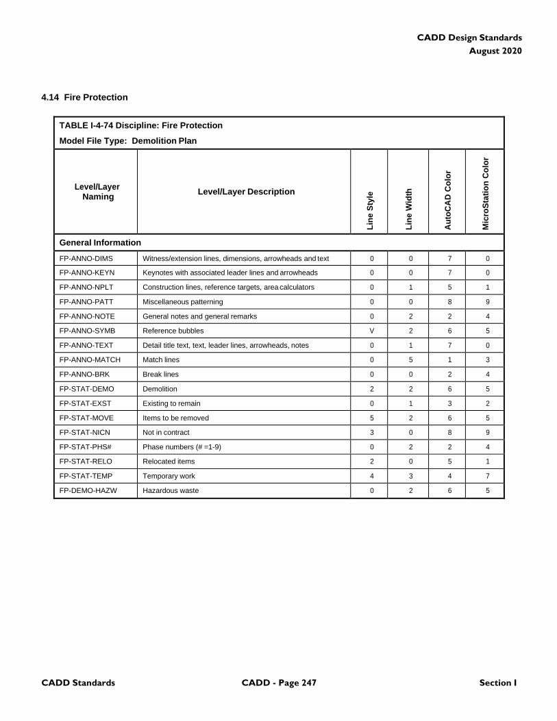
CADD Standards CADD - Page 247 Section I
CADD Design Standards
August 2020
4.14 Fire Protection
TABLE I-4-74 Discipline: Fire Protection
Model File Type: Demolition Plan
Level/Layer
Naming
Level/Layer Description
Lin
e S
tyle
Lin
e W
idth
Au
toC
AD
Co
lor
Mic
roS
tati
on
Co
lor
General Information
FP-ANNO-DIMS Witness/extension lines, dimensions, arrowheads and text 0 0 7 0
FP-ANNO-KEYN Keynotes with associated leader lines and arrowheads 0 0 7 0
FP-ANNO-NPLT Construction lines, reference targets, area calculators 0 1 5 1
FP-ANNO-PATT Miscellaneous patterning 0 0 8 9
FP-ANNO-NOTE General notes and general remarks 0 2 2 4
FP-ANNO-SYMB Reference bubbles V 2 6 5
FP-ANNO-TEXT Detail title text, text, leader lines, arrowheads, notes 0 1 7 0
FP-ANNO-MATCH Match lines 0 5 1 3
FP-ANNO-BRK Break lines 0 0 2 4
FP-STAT-DEMO Demolition 2 2 6 5
FP-STAT-EXST Existing to remain 0 1 3 2
FP-STAT-MOVE Items to be removed 5 2 6 5
FP-STAT-NICN Not in contract 3 0 8 9
FP-STAT-PHS# Phase numbers (# =1-9) 0 2 2 4
FP-STAT-RELO Relocated items 2 0 5 1
FP-STAT-TEMP Temporary work 4 3 4 7
FP-DEMO-HAZW Hazardous waste 0 2 6 5
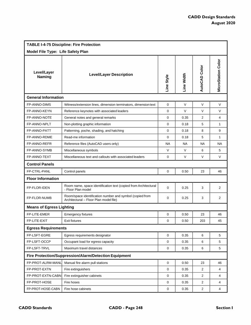
CADD Standards CADD - Page 248 Section I
CADD Design Standards
August 2020
TABLE I-4-75 Discipline: Fire Protection
Model File Type: Life Safety Plan
Level/Layer
Naming
Level/Layer Description
Lin
e S
tyle
Lin
e W
idth
Au
toC
AD
Co
lor
Mic
roS
tati
on
Co
lor
General Information
FP-ANNO-DIMS Witness/extension lines, dimension terminators, dimension text 0 V V V
FP-ANNO-KEYN Reference keynotes with associated leaders 0 V V V
FP-ANNO-NOTE General notes and general remarks 0 0.35 2 4
FP-ANNO-NPLT Non-plotting graphic information 0 0.18 5 1
FP-ANNO-PATT Patterning, poche, shading, and hatching 0 0.18 8 9
FP-ANNO-RDME Read-me information 0 0.18 5 1
FP-ANNO-REFR Reference files (AutoCAD users only) NA NA NA NA
FP-ANNO-SYMB Miscellaneous symbols V V 6 5
FP-ANNO-TEXT Miscellaneous text and callouts with associated leaders 0 V V V
Control Panels
FP-CTRL-PANL Control panels 0 0.50 23 46
Floor Information
FP-FLOR-IDEN Room name, space identification text (copied from Architectural - Floor Plan model
0
0.25
3
2
FP-FLOR-NUMB Room/space identification number and symbol (copied from Architectural – Floor Plan model file)
0
0.25
3
2
Means of Egress Lighting
FP-LITE-EMER Emergency fixtures 0 0.50 23 46
FP-LITE-EXIT Exit fixtures 0 0.50 203 45
Egress Requirements
FP-LSFT-EGRE Egress requirements designator 0 0.35 6 5
FP-LSFT-OCCP Occupant load for egress capacity 0 0.35 6 5
FP-LSFT-TRVL Maximum travel distances 0 0.35 6 5
Fire Protection/Suppression/Alarm/Detection Equipment
FP-PROT-ALRM-MANL Manual fire alarm pull stations 0 0.50 23 46
FP-PROT-EXTN Fire extinguishers 0 0.35 2 4
FP-PROT-EXTN-CABN Fire extinguisher cabinets 0 0.35 2 4
FP-PROT-HOSE Fire hoses 0 0.35 2 4
FP-PROT-HOSE-CABN Fire hose cabinets 0 0.35 2 4

CADD Standards CADD - Page 249 Section I
CADD Design Standards
August 2020
TABLE I-4-75 Discipline: Fire Protection
Model File Type: Life Safety Plan
Level/Layer
Naming
Level/Layer Description
Lin
e S
tyle
Lin
e W
idth
Au
toC
AD
Co
lor
Mic
roS
tati
on
Co
lor
Fire Ratings
FP-RATE-DOOR Door fire ratings 0 0.50 4 7
FP-RATE-WALL Wall fire ratings 0 0.50 4 7
Smoke/Pressurization Control
FP-SMOK-DMPR Dampers 0 0.35 22 22
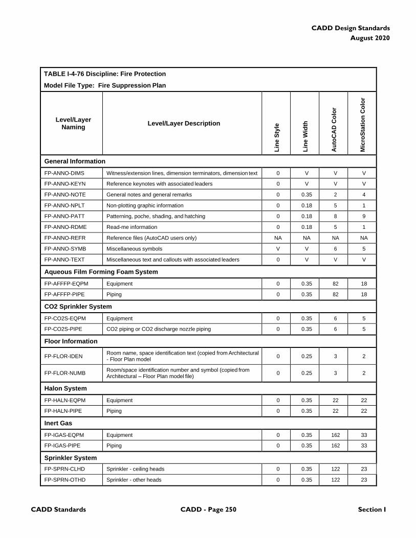
CADD Standards CADD - Page 250 Section I
CADD Design Standards
August 2020
TABLE I-4-76 Discipline: Fire Protection
Model File Type: Fire Suppression Plan
Level/Layer
Naming
Level/Layer Description
Lin
e S
tyle
Lin
e W
idth
Au
toC
AD
Co
lor
Mic
roS
tati
on
Co
lor
General Information
FP-ANNO-DIMS Witness/extension lines, dimension terminators, dimension text 0 V V V
FP-ANNO-KEYN Reference keynotes with associated leaders 0 V V V
FP-ANNO-NOTE General notes and general remarks 0 0.35 2 4
FP-ANNO-NPLT Non-plotting graphic information 0 0.18 5 1
FP-ANNO-PATT Patterning, poche, shading, and hatching 0 0.18 8 9
FP-ANNO-RDME Read-me information 0 0.18 5 1
FP-ANNO-REFR Reference files (AutoCAD users only) NA NA NA NA
FP-ANNO-SYMB Miscellaneous symbols V V 6 5
FP-ANNO-TEXT Miscellaneous text and callouts with associated leaders 0 V V V
Aqueous Film Forming Foam System
FP-AFFFP-EQPM Equipment 0 0.35 82 18
FP-AFFFP-PIPE Piping 0 0.35 82 18
CO2 Sprinkler System
FP-CO2S-EQPM Equipment 0 0.35 6 5
FP-CO2S-PIPE CO2 piping or CO2 discharge nozzle piping 0 0.35 6 5
Floor Information
FP-FLOR-IDEN Room name, space identification text (copied from Architectural - Floor Plan model
0
0.25
3
2
FP-FLOR-NUMB Room/space identification number and symbol (copied from Architectural – Floor Plan model file)
0
0.25
3
2
Halon System
FP-HALN-EQPM Equipment 0 0.35 22 22
FP-HALN-PIPE Piping 0 0.35 22 22
Inert Gas
FP-IGAS-EQPM Equipment 0 0.35 162 33
FP-IGAS-PIPE Piping 0 0.35 162 33
Sprinkler System
FP-SPRN-CLHD Sprinkler - ceiling heads 0 0.35 122 23
FP-SPRN-OTHD Sprinkler - other heads 0 0.35 122 23
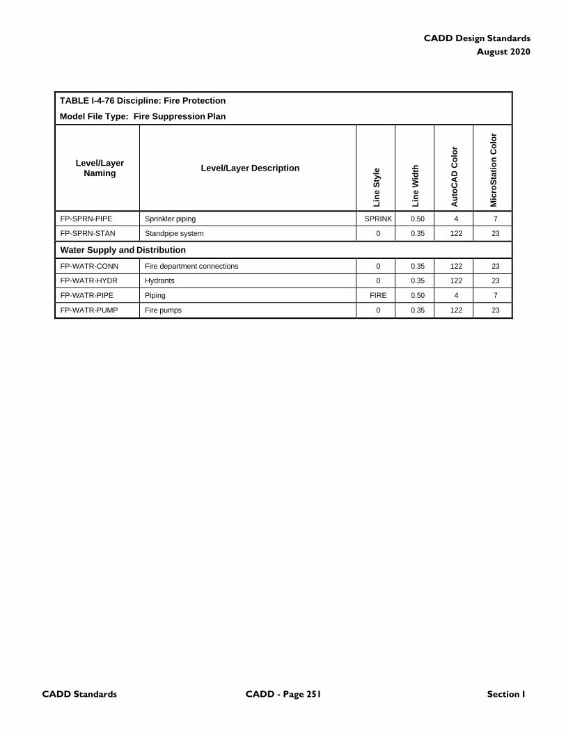
CADD Standards CADD - Page 251 Section I
CADD Design Standards
August 2020
TABLE I-4-76 Discipline: Fire Protection
Model File Type: Fire Suppression Plan
Level/Layer
Naming
Level/Layer Description
Lin
e S
tyle
Lin
e W
idth
Au
toC
AD
Co
lor
Mic
roS
tati
on
Co
lor
FP-SPRN-PIPE Sprinkler piping SPRINK 0.50 4 7
FP-SPRN-STAN Standpipe system 0 0.35 122 23
Water Supply and Distribution
FP-WATR-CONN Fire department connections 0 0.35 122 23
FP-WATR-HYDR Hydrants 0 0.35 122 23
FP-WATR-PIPE Piping FIRE 0.50 4 7
FP-WATR-PUMP Fire pumps 0 0.35 122 23
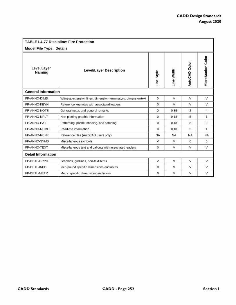
CADD Standards CADD - Page 252 Section I
CADD Design Standards
August 2020
TABLE I-4-77 Discipline: Fire Protection
Model File Type: Details
Level/Layer
Naming
Level/Layer Description
Lin
e S
tyle
Lin
e W
idth
Au
toC
AD
Co
lor
Mic
roS
tati
on
Co
lor
General Information
FP-ANNO-DIMS Witness/extension lines, dimension terminators, dimension text 0 V V V
FP-ANNO-KEYN Reference keynotes with associated leaders 0 V V V
FP-ANNO-NOTE General notes and general remarks 0 0.35 2 4
FP-ANNO-NPLT Non-plotting graphic information 0 0.18 5 1
FP-ANNO-PATT Patterning, poche, shading, and hatching 0 0.18 8 9
FP-ANNO-RDME Read-me information 0 0.18 5 1
FP-ANNO-REFR Reference files (AutoCAD users only) NA NA NA NA
FP-ANNO-SYMB Miscellaneous symbols V V 6 5
FP-ANNO-TEXT Miscellaneous text and callouts with associated leaders 0 V V V
Detail Information
FP-DETL-GRPH Graphics, gridlines, non-text items V V V V
FP-DETL-INPD Inch-pound specific dimensions and notes 0 V V V
FP-DETL-METR Metric specific dimensions and notes 0 V V V
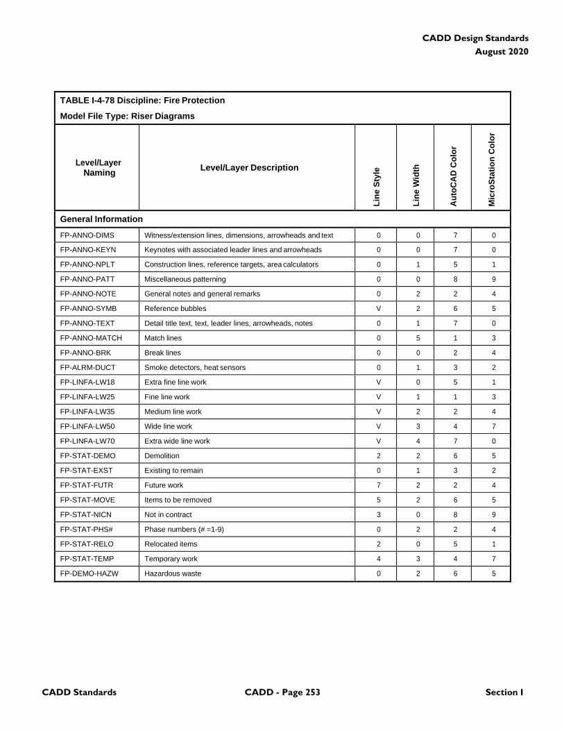
CADD Standards CADD - Page 253 Section I
CADD Design Standards
August 2020
TABLE I-4-78 Discipline: Fire Protection
Model File Type: Riser Diagrams
Level/Layer
Naming
Level/Layer Description
Lin
e S
tyle
Lin
e W
idth
Au
toC
AD
Co
lor
Mic
roS
tati
on
Co
lor
General Information
FP-ANNO-DIMS Witness/extension lines, dimensions, arrowheads and text 0 0 7 0
FP-ANNO-KEYN Keynotes with associated leader lines and arrowheads 0 0 7 0
FP-ANNO-NPLT Construction lines, reference targets, area calculators 0 1 5 1
FP-ANNO-PATT Miscellaneous patterning 0 0 8 9
FP-ANNO-NOTE General notes and general remarks 0 2 2 4
FP-ANNO-SYMB Reference bubbles V 2 6 5
FP-ANNO-TEXT Detail title text, text, leader lines, arrowheads, notes 0 1 7 0
FP-ANNO-MATCH Match lines 0 5 1 3
FP-ANNO-BRK Break lines 0 0 2 4
FP-ALRM-DUCT Smoke detectors, heat sensors 0 1 3 2
FP-LINFA-LW18 Extra fine line work V 0 5 1
FP-LINFA-LW25 Fine line work V 1 1 3
FP-LINFA-LW35 Medium line work V 2 2 4
FP-LINFA-LW50 Wide line work V 3 4 7
FP-LINFA-LW70 Extra wide line work V 4 7 0
FP-STAT-DEMO Demolition 2 2 6 5
FP-STAT-EXST Existing to remain 0 1 3 2
FP-STAT-FUTR Future work 7 2 2 4
FP-STAT-MOVE Items to be removed 5 2 6 5
FP-STAT-NICN Not in contract 3 0 8 9
FP-STAT-PHS# Phase numbers (# =1-9) 0 2 2 4
FP-STAT-RELO Relocated items 2 0 5 1
FP-STAT-TEMP Temporary work 4 3 4 7
FP-DEMO-HAZW Hazardous waste 0 2 6 5
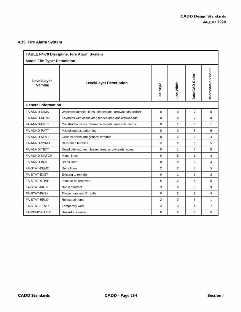
CADD Standards CADD - Page 254 Section I
CADD Design Standards
August 2020
4.15 Fire Alarm System
TABLE I-4-79 Discipline: Fire Alarm System
Model File Type: Demolition
Level/Layer
Naming
Level/Layer Description
Lin
e S
tyle
Lin
e W
idth
Au
toC
AD
Co
lor
Mic
roS
tati
on
Co
lor
General Information
FA-ANNO-DIMS Witness/extension lines, dimensions, arrowheads and text 0 0 7 0
FA-ANNO-KEYN Keynotes with associated leader lines and arrowheads 0 0 7 0
FA-ANNO-NPLT Construction lines, reference targets, area calculators 0 1 5 1
FA-ANNO-PATT Miscellaneous patterning 0 0 8 9
FA-ANNO-NOTE General notes and general remarks 0 2 2 4
FA-ANNO-SYMB Reference bubbles V 2 6 5
FA-ANNO-TEXT Detail title text, text, leader lines, arrowheads, notes 0 1 7 0
FA-ANNO-MATCH Match lines 0 5 1 3
FA-ANNO-BRK Break lines 0 0 2 4
FA-STAT-DEMO Demolition 2 2 6 5
FA-STAT-EXST Existing to remain 0 1 3 2
FA-STAT-MOVE Items to be removed 5 2 6 5
FA-STAT-NICN Not in contract 3 0 8 9
FA-STAT-PHS# Phase numbers (# =1-9) 0 2 2 4
FA-STAT-RELO Relocated items 2 0 5 1
FA-STAT-TEMP Temporary work 4 3 4 7
FA-DEMO-HAZW Hazardous waste 0 2 6 5
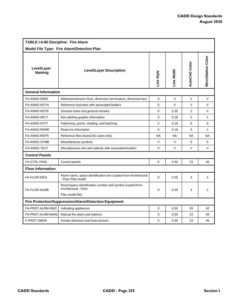
CADD Standards CADD - Page 255 Section I
CADD Design Standards
August 2020
TABLE I-4-80 Discipline: Fire Alarm
Model File Type: Fire Alarm/Detection Plan
Level/Layer
Naming
Level/Layer Description
Lin
e S
tyle
Lin
e W
idth
Au
toC
AD
Co
lor
Mic
roS
tati
on
Co
lor
General Information
FA-ANNO-DIMS Witness/extension lines, dimension terminators, dimension text 0 V V V
FA-ANNO-KEYN Reference keynotes with associated leaders 0 V V V
FA-ANNO-NOTE General notes and general remarks 0 0.35 2 4
FA-ANNO-NPLT Non-plotting graphic information 0 0.18 5 1
FA-ANNO-PATT Patterning, poche, shading, and hatching V 0.18 8 9
FA-ANNO-RDME Read-me information 0 0.18 5 1
FA-ANNO-REFR Reference files (AutoCAD users only) NA NA NA NA
FA-ANNO-SYMB Miscellaneous symbols V V 6 5
FA-ANNO-TEXT Miscellaneous text and callouts with associated leaders 0 V V V
Control Panels
FA-CTRL-PANL Control panels 0 0.50 23 46
Floor Information
FA-FLOR-IDEN Room name, space identification text (copied from Architectural - Floor Plan model
0
0.25
3
2
FA-FLOR-NUMB
Room/space identification number and symbol (copied from Architectural - Floor
Plan model file)
0
0.25
3
2
Fire Protection/Suppression/Alarm/Detection Equipment
FA-PROT-ALRM-INDC Indicating appliances 0 0.50 83 42
FA-PROT-ALRM-MANL Manual fire alarm pull stations 0 0.50 23 46
F-PROT-SMOK Smoke detectors and heat sensors 0 0.50 23 46
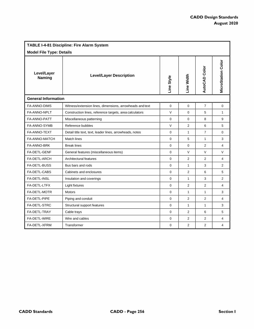
CADD Standards CADD - Page 256 Section I
CADD Design Standards
August 2020
TABLE I-4-81 Discipline: Fire Alarm System
Model File Type: Details
Level/Layer
Naming
Level/Layer Description
Lin
e S
tyle
Lin
e W
idth
Au
toC
AD
Co
lor
Mic
roS
tati
on
Co
lor
General Information
FA-ANNO-DIMS Witness/extension lines, dimensions, arrowheads and text 0 0 7 0
FA-ANNO-NPLT Construction lines, reference targets, area calculators V 0 5 1
FA-ANNO-PATT Miscellaneous patterning 0 0 8 9
FA-ANNO-SYMB Reference bubbles V 2 6 5
FA-ANNO-TEXT Detail title text, text, leader lines, arrowheads, notes 0 1 7 0
FA-ANNO-MATCH Match lines 0 5 1 3
FA-ANNO-BRK Break lines 0 0 2 4
FA-DETL-GENF General features (miscellaneous items) 0 V V V
FA-DETL-ARCH Architectural features 0 2 2 4
FA-DETL-BUSS Bus bars and rods 0 1 3 2
FA-DETL-CABS Cabinets and enclosures 0 2 6 5
FA-DETL-INSL Insulation and coverings 0 1 3 2
FA-DETL-LTFX Light fixtures 0 2 2 4
FA-DETL-MOTR Motors 0 1 1 3
FA-DETL-PIPE Piping and conduit 0 2 2 4
FA-DETL-STRC Structural support features 0 1 1 3
FA-DETL-TRAY Cable trays 0 2 6 5
FA-DETL-WIRE Wire and cables 0 2 2 4
FA-DETL-XFRM Transformer 0 2 2 4
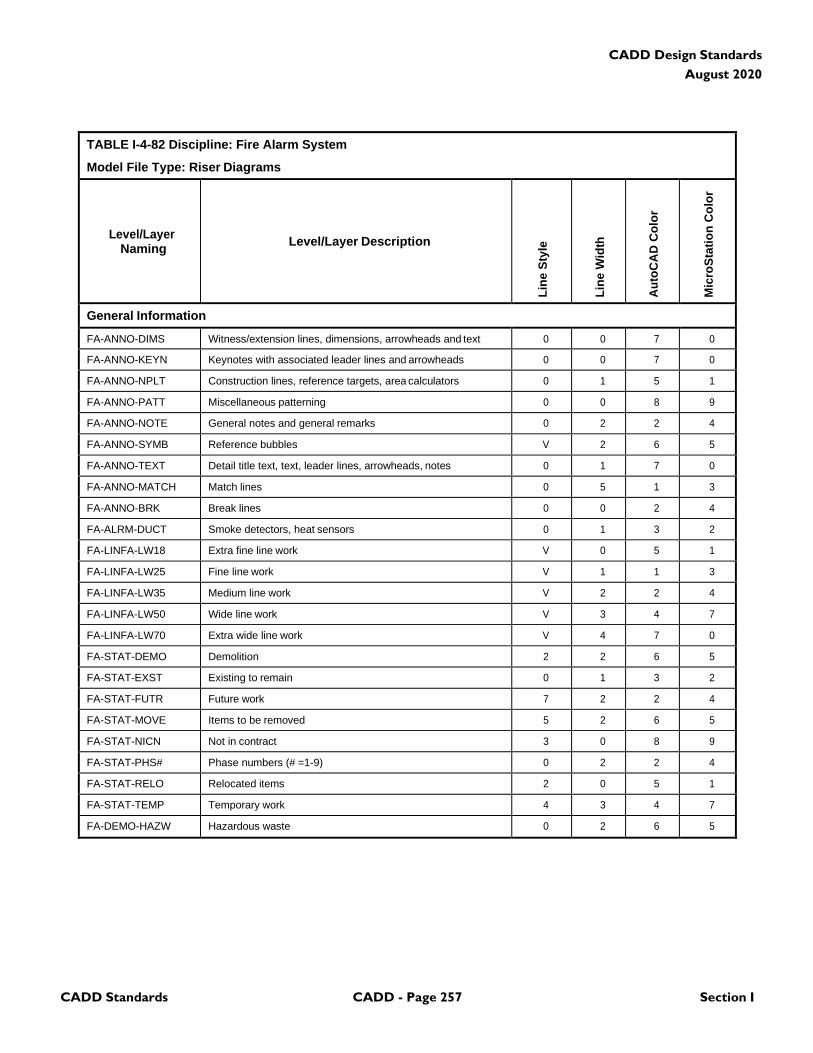
CADD Standards CADD - Page 257 Section I
CADD Design Standards
August 2020
TABLE I-4-82 Discipline: Fire Alarm System
Model File Type: Riser Diagrams
Level/Layer
Naming
Level/Layer Description
Lin
e S
tyle
Lin
e W
idth
Au
toC
AD
Co
lor
Mic
roS
tati
on
Co
lor
General Information
FA-ANNO-DIMS Witness/extension lines, dimensions, arrowheads and text 0 0 7 0
FA-ANNO-KEYN Keynotes with associated leader lines and arrowheads 0 0 7 0
FA-ANNO-NPLT Construction lines, reference targets, area calculators 0 1 5 1
FA-ANNO-PATT Miscellaneous patterning 0 0 8 9
FA-ANNO-NOTE General notes and general remarks 0 2 2 4
FA-ANNO-SYMB Reference bubbles V 2 6 5
FA-ANNO-TEXT Detail title text, text, leader lines, arrowheads, notes 0 1 7 0
FA-ANNO-MATCH Match lines 0 5 1 3
FA-ANNO-BRK Break lines 0 0 2 4
FA-ALRM-DUCT Smoke detectors, heat sensors 0 1 3 2
FA-LINFA-LW18 Extra fine line work V 0 5 1
FA-LINFA-LW25 Fine line work V 1 1 3
FA-LINFA-LW35 Medium line work V 2 2 4
FA-LINFA-LW50 Wide line work V 3 4 7
FA-LINFA-LW70 Extra wide line work V 4 7 0
FA-STAT-DEMO Demolition 2 2 6 5
FA-STAT-EXST Existing to remain 0 1 3 2
FA-STAT-FUTR Future work 7 2 2 4
FA-STAT-MOVE Items to be removed 5 2 6 5
FA-STAT-NICN Not in contract 3 0 8 9
FA-STAT-PHS# Phase numbers (# =1-9) 0 2 2 4
FA-STAT-RELO Relocated items 2 0 5 1
FA-STAT-TEMP Temporary work 4 3 4 7
FA-DEMO-HAZW Hazardous waste 0 2 6 5

CADD Standards CADD - Page 258 Section I
CADD Design Standards
August 2020
4.16 Plumbing
TABLE I-4-83 Discipline: Plumbing
Model File Type: Demolition Plan
Level/Layer
Naming
Level/Layer Description
Lin
e S
tyle
Lin
e W
idth
Au
toC
AD
Co
lor
Mic
roS
tati
on
Co
lor
General Information
PL-ANNO-DIMS Witness extension lines, dimensions arrowheads and text 0 V V V
PL-ANNO-KEYN Keynote with associated leaderlines and arrowheads 0 V V V
PL-ANNO-NPLT Construction lines, reference targets, area calculations V 0 5 1
PL-ANNO-PATT Miscellaneous patterning 0 0 8 9
PL-ANNO-NOTE General note and general remarks 0 2 2 4
PL-ANNO-SYMB Reference bubbles, matchlines, breaklines V 2 6 5
PL-ANNO-TEXT Detail title text, leaderlines, arrowheads, notes 0 V V V
PL-STAT-DEMO Demolition 2 2 6 5
PL-STAT-EXST Existing to remain 0 1 3 2
PL-STAT-MOVE Items to be moved 5 2 6 5
PL-STAT-NICN Not in contract 3 0 8 9
PL-STAT-PHS# Phase numbers (# = 1-9) 0 2 2 4
PL-STAT-RELO Relocated items 2 0 5 1
PL-STAT-TEMP Temporary work 4 3 4 7
PL-DEMO-HAZW Hazardous waste 0 2 6 5
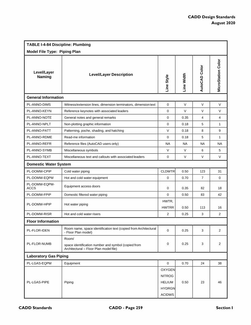
CADD Standards CADD - Page 259 Section I
CADD Design Standards
August 2020
TABLE I-4-84 Discipline: Plumbing
Model File Type: Piping Plan
Level/Layer
Naming
Level/Layer Description
Lin
e S
tyle
Lin
e W
idth
Au
toC
AD
Co
lor
Mic
roS
tati
on
Co
lor
General Information
PL-ANNO-DIMS Witness/extension lines, dimension terminators, dimension text 0 V V V
PL-ANNO-KEYN Reference keynotes with associated leaders 0 V V V
PL-ANNO-NOTE General notes and general remarks 0 0.35 4 4
PL-ANNO-NPLT Non-plotting graphic information 0 0.18 5 1
PL-ANNO-PATT Patterning, poche, shading, and hatching V 0.18 8 9
PL-ANNO-RDME Read-me information 0 0.18 5 1
PL-ANNO-REFR Reference files (AutoCAD users only) NA NA NA NA
PL-ANNO-SYMB Miscellaneous symbols V V 6 5
PL-ANNO-TEXT Miscellaneous text and callouts with associated leaders 0 V V V
Domestic Water System
PL-DOMW-CPIP Cold water piping CLDWTR 0.50 123 31
PL-DOMW-EQPM Hot and cold water equipment 0 0.70 7 0
PL-DOMW-EQPM- ACCS
Equipment access doors
0
0.35
82
18
PL-DOMW-FPIP Domestic filtered water piping 0 0.50 83 42
PL-DOMW-HPIP
Hot water piping
HWTR,
HWTRR
0.50
113
16
PL-DOMW-RISR Hot and cold water risers 2 0.25 3 2
Floor Information
PL-FLOR-IDEN Room name, space identification text (copied from Architectural - Floor Plan model)
0
0.25
3
2
PL-FLOR-NUMB
Room/
space identification number and symbol (copied from Architectural – Floor Plan model file)
0
0.25
3
2
Laboratory Gas Piping
PL-LGAS-EQPM Equipment 0 0.70 24 38
PL-LGAS-PIPE
Piping
OXYGEN
NITROG
HELIUM
HYDRGN
ACIDWS
0.50
23
46
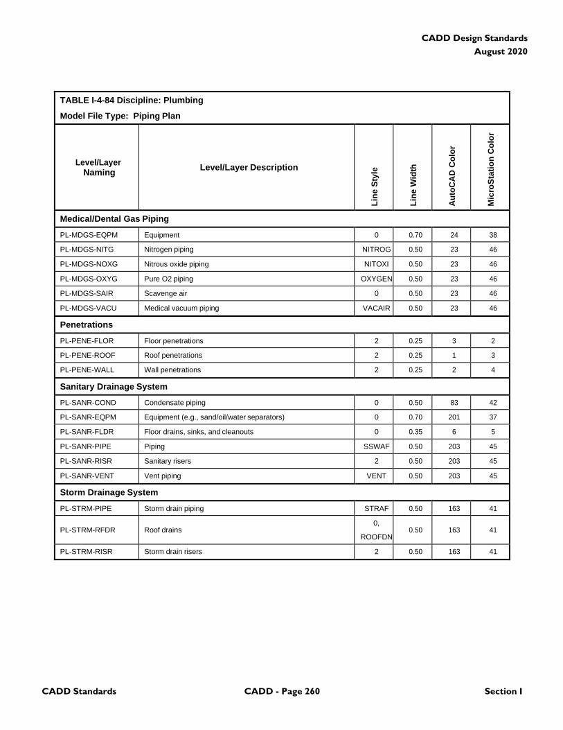
CADD Standards CADD - Page 260 Section I
CADD Design Standards
August 2020
TABLE I-4-84 Discipline: Plumbing
Model File Type: Piping Plan
Level/Layer
Naming
Level/Layer Description
Lin
e S
tyle
Lin
e W
idth
Au
toC
AD
Co
lor
Mic
roS
tati
on
Co
lor
Medical/Dental Gas Piping
PL-MDGS-EQPM Equipment 0 0.70 24 38
PL-MDGS-NITG Nitrogen piping NITROG 0.50 23 46
PL-MDGS-NOXG Nitrous oxide piping NITOXI 0.50 23 46
PL-MDGS-OXYG Pure O2 piping OXYGEN 0.50 23 46
PL-MDGS-SAIR Scavenge air 0 0.50 23 46
PL-MDGS-VACU Medical vacuum piping VACAIR 0.50 23 46
Penetrations
PL-PENE-FLOR Floor penetrations 2 0.25 3 2
PL-PENE-ROOF Roof penetrations 2 0.25 1 3
PL-PENE-WALL Wall penetrations 2 0.25 2 4
Sanitary Drainage System
PL-SANR-COND Condensate piping 0 0.50 83 42
PL-SANR-EQPM Equipment (e.g., sand/oil/water separators) 0 0.70 201 37
PL-SANR-FLDR Floor drains, sinks, and cleanouts 0 0.35 6 5
PL-SANR-PIPE Piping SSWAF 0.50 203 45
PL-SANR-RISR Sanitary risers 2 0.50 203 45
PL-SANR-VENT Vent piping VENT 0.50 203 45
Storm Drainage System
PL-STRM-PIPE Storm drain piping STRAF 0.50 163 41
PL-STRM-RFDR
Roof drains
0,
ROOFDN
0.50
163
41
PL-STRM-RISR Storm drain risers 2 0.50 163 41
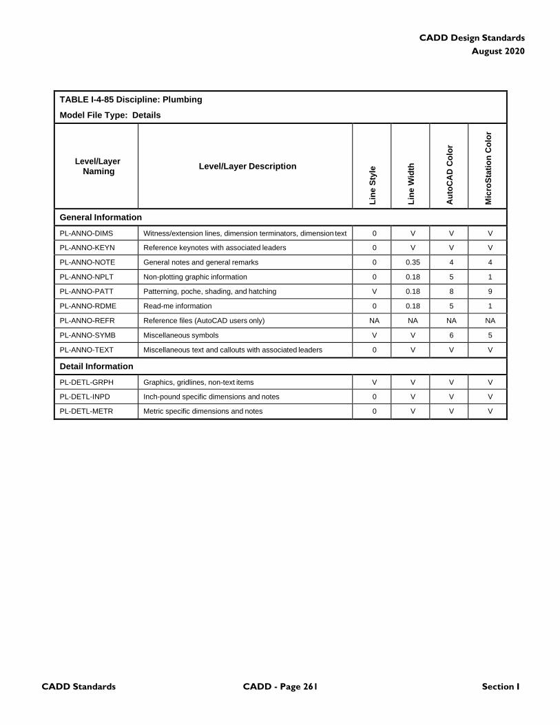
CADD Standards CADD - Page 261 Section I
CADD Design Standards
August 2020
TABLE I-4-85 Discipline: Plumbing
Model File Type: Details
Level/Layer
Naming
Level/Layer Description
Lin
e S
tyle
Lin
e W
idth
Au
toC
AD
Co
lor
Mic
roS
tati
on
Co
lor
General Information
PL-ANNO-DIMS Witness/extension lines, dimension terminators, dimension text 0 V V V
PL-ANNO-KEYN Reference keynotes with associated leaders 0 V V V
PL-ANNO-NOTE General notes and general remarks 0 0.35 4 4
PL-ANNO-NPLT Non-plotting graphic information 0 0.18 5 1
PL-ANNO-PATT Patterning, poche, shading, and hatching V 0.18 8 9
PL-ANNO-RDME Read-me information 0 0.18 5 1
PL-ANNO-REFR Reference files (AutoCAD users only) NA NA NA NA
PL-ANNO-SYMB Miscellaneous symbols V V 6 5
PL-ANNO-TEXT Miscellaneous text and callouts with associated leaders 0 V V V
Detail Information
PL-DETL-GRPH Graphics, gridlines, non-text items V V V V
PL-DETL-INPD Inch-pound specific dimensions and notes 0 V V V
PL-DETL-METR Metric specific dimensions and notes 0 V V V
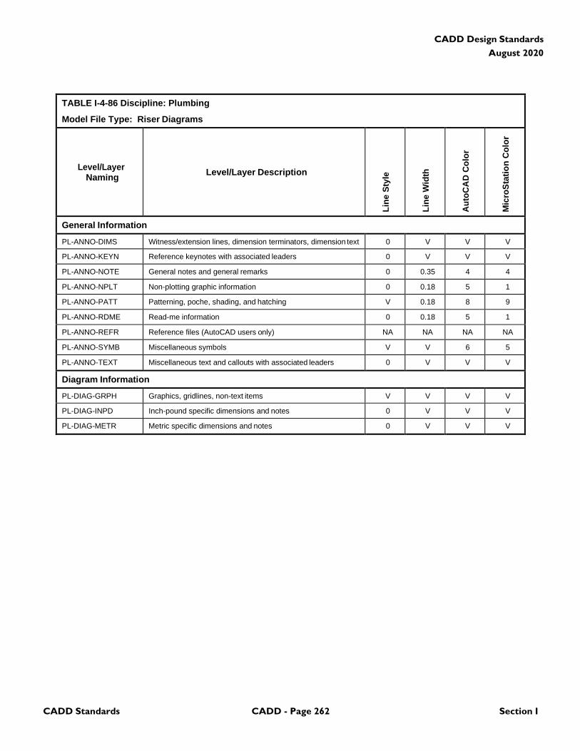
CADD Standards CADD - Page 262 Section I
CADD Design Standards
August 2020
TABLE I-4-86 Discipline: Plumbing
Model File Type: Riser Diagrams
Level/Layer
Naming
Level/Layer Description
Lin
e S
tyle
Lin
e W
idth
Au
toC
AD
Co
lor
Mic
roS
tati
on
Co
lor
General Information
PL-ANNO-DIMS Witness/extension lines, dimension terminators, dimension text 0 V V V
PL-ANNO-KEYN Reference keynotes with associated leaders 0 V V V
PL-ANNO-NOTE General notes and general remarks 0 0.35 4 4
PL-ANNO-NPLT Non-plotting graphic information 0 0.18 5 1
PL-ANNO-PATT Patterning, poche, shading, and hatching V 0.18 8 9
PL-ANNO-RDME Read-me information 0 0.18 5 1
PL-ANNO-REFR Reference files (AutoCAD users only) NA NA NA NA
PL-ANNO-SYMB Miscellaneous symbols V V 6 5
PL-ANNO-TEXT Miscellaneous text and callouts with associated leaders 0 V V V
Diagram Information
PL-DIAG-GRPH Graphics, gridlines, non-text items V V V V
PL-DIAG-INPD Inch-pound specific dimensions and notes 0 V V V
PL-DIAG-METR Metric specific dimensions and notes 0 V V V

CADD Standards CADD - Page 263 Section I
CADD Design Standards
August 2020
4.17 Mechanical
TABLE I-4-87 Discipline: Mechanical
Model File Type: Demolition Plan
Level/Layer
Naming
Level/Layer Description
Lin
e S
tyle
Lin
e W
idth
Au
toC
AD
Co
lor
Mic
roS
tati
on
Co
lor
General Information
ME-ANNO-DIMS Witness extension lines, dimensions arrowheads and text 0 V V V
ME-ANNO-KEYN Keynote with associated leaderlines and arrowheads 0 V V V
ME-ANNO-NPLT Construction lines, reference targets, area calculations V 0 5 1
ME-ANNO-PATT Miscellaneous patterning 0 0 8 9
ME-ANNO-NOTE General note and general remarks 0 2 2 4
ME-ANNO-SYMB Reference bubbles, matchlines, breaklines V 2 6 5
ME-ANNO-TEXT Detail title text, leaderlines, arrowheads, notes 0 V V V
ME-STAT-DEMO Demolition 2 2 6 5
ME-STAT-EXST Existing to remain 0 1 3 2
ME-STAT-MOVE Items to be moved 5 2 6 5
ME-STAT-NICN Not in contract 3 0 8 9
ME-STAT-PHS# Phase numbers (# = 1-9) 0 2 2 4
ME-STAT-RELO Relocated items 2 0 5 1
ME-STAT-TEMP Temporary work 4 3 4 7
ME-DEMO-HAZW Hazardous waste 0 2 6 5
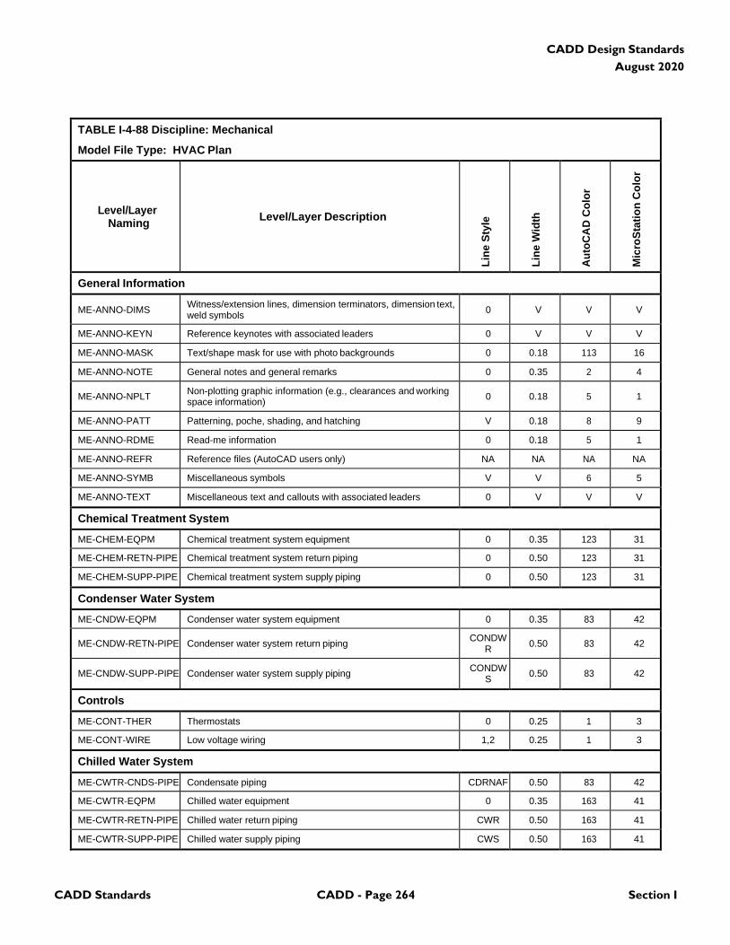
CADD Standards CADD - Page 264 Section I
CADD Design Standards
August 2020
TABLE I-4-88 Discipline: Mechanical
Model File Type: HVAC Plan
Level/Layer
Naming
Level/Layer Description
Lin
e S
tyle
Lin
e W
idth
Au
toC
AD
Co
lor
Mic
roS
tati
on
Co
lor
General Information
ME-ANNO-DIMS Witness/extension lines, dimension terminators, dimension text, weld symbols
0
V
V
V
ME-ANNO-KEYN Reference keynotes with associated leaders 0 V V V
ME-ANNO-MASK Text/shape mask for use with photo backgrounds 0 0.18 113 16
ME-ANNO-NOTE General notes and general remarks 0 0.35 2 4
ME-ANNO-NPLT Non-plotting graphic information (e.g., clearances and working space information)
0
0.18
5
1
ME-ANNO-PATT Patterning, poche, shading, and hatching V 0.18 8 9
ME-ANNO-RDME Read-me information 0 0.18 5 1
ME-ANNO-REFR Reference files (AutoCAD users only) NA NA NA NA
ME-ANNO-SYMB Miscellaneous symbols V V 6 5
ME-ANNO-TEXT Miscellaneous text and callouts with associated leaders 0 V V V
Chemical Treatment System
ME-CHEM-EQPM Chemical treatment system equipment 0 0.35 123 31
ME-CHEM-RETN-PIPE Chemical treatment system return piping 0 0.50 123 31
ME-CHEM-SUPP-PIPE Chemical treatment system supply piping 0 0.50 123 31
Condenser Water System
ME-CNDW-EQPM Condenser water system equipment 0 0.35 83 42
ME-CNDW-RETN-PIPE
Condenser water system return piping CONDW
R
0.50
83
42
ME-CNDW-SUPP-PIPE
Condenser water system supply piping CONDW
S
0.50
83
42
Controls
ME-CONT-THER Thermostats 0 0.25 1 3
ME-CONT-WIRE Low voltage wiring 1,2 0.25 1 3
Chilled Water System
ME-CWTR-CNDS-PIPE Condensate piping CDRNAF 0.50 83 42
ME-CWTR-EQPM Chilled water equipment 0 0.35 163 41
ME-CWTR-RETN-PIPE Chilled water return piping CWR 0.50 163 41
ME-CWTR-SUPP-PIPE Chilled water supply piping CWS 0.50 163 41
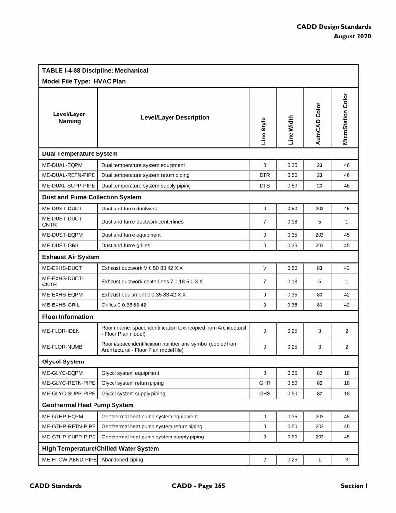
CADD Standards CADD - Page 265 Section I
CADD Design Standards
August 2020
TABLE I-4-88 Discipline: Mechanical
Model File Type: HVAC Plan
Level/Layer
Naming
Level/Layer Description
Lin
e S
tyle
Lin
e W
idth
Au
toC
AD
Co
lor
Mic
roS
tati
on
Co
lor
Dual Temperature System
ME-DUAL-EQPM Dual temperature system equipment 0 0.35 23 46
ME-DUAL-RETN-PIPE Dual temperature system return piping DTR 0.50 23 46
ME-DUAL-SUPP-PIPE Dual temperature system supply piping DTS 0.50 23 46
Dust and Fume Collection System
ME-DUST-DUCT Dust and fume ductwork 0 0.50 203 45
ME-DUST-DUCT- CNTR
Dust and fume ductwork centerlines
7
0.18
5
1
ME-DUST-EQPM Dust and fume equipment 0 0.35 203 45
ME-DUST-GRIL Dust and fume grilles 0 0.35 203 45
Exhaust Air System
ME-EXHS-DUCT Exhaust ductwork V 0.50 83 42 X X V 0.50 83 42
ME-EXHS-DUCT- CNTR
Exhaust ductwork centerlines 7 0.18 5 1 X X
7
0.18
5
1
ME-EXHS-EQPM Exhaust equipment 0 0.35 83 42 X X 0 0.35 83 42
ME-EXHS-GRIL Grilles 0 0.35 83 42 0 0.35 83 42
Floor Information
ME-FLOR-IDEN Room name, space identification text (copied from Architectural - Floor Plan model)
0
0.25
3
2
ME-FLOR-NUMB Room/space identification number and symbol (copied from Architectural - Floor Plan model file)
0
0.25
3
2
Glycol System
ME-GLYC-EQPM Glycol system equipment 0 0.35 82 18
ME-GLYC-RETN-PIPE Glycol system return piping GHR 0.50 82 18
ME-GLYC-SUPP-PIPE Glycol system supply piping GHS 0.50 82 18
Geothermal Heat Pump System
ME-GTHP-EQPM Geothermal heat pump system equipment 0 0.35 203 45
ME-GTHP-RETN-PIPE Geothermal heat pump system return piping 0 0.50 203 45
ME-GTHP-SUPP-PIPE Geothermal heat pump system supply piping 0 0.50 203 45
High Temperature/Chilled Water System
ME-HTCW-ABND-PIPE Abandoned piping 2 0.25 1 3
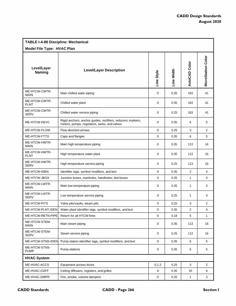
CADD Standards CADD - Page 266 Section I
CADD Design Standards
August 2020
TABLE I-4-88 Discipline: Mechanical
Model File Type: HVAC Plan
Level/Layer
Naming
Level/Layer Description
Lin
e S
tyle
Lin
e W
idth
Au
toC
AD
Co
lor
Mic
roS
tati
on
Co
lor
ME-HTCW-CWTR- MAIN
Main chilled water piping
0
0.35
163
41
ME-HTCW-CWTR- PLNT
Chilled water plant
0
0.35
163
41
ME-HTCW-CWTR- SERV
Chilled water service piping
0
0.25
163
41
ME-HTCW-DEVC Rigid anchors, anchor guides, rectifiers, reducers, markers, meters, pumps, regulators, tanks, and valves
0
0.35
6
5
ME-HTCW-FLOW Flow direction arrows 0 0.25 3 2
ME-HTCW-FTTG Caps and flanges 0 0.35 6 5
ME-HTCW-HWTR- MAIN
Main high temperature piping
0
0.35
113
16
ME-HTCW-HWTR- PLNT
High temperature water plant
0
0.35
113
16
ME-HTCW-HWTR- SERV
High temperature service piping
0
0.25
113
16
ME-HTCW-IDEN Identifier tags, symbol modifiers, and text 0 0.35 2 4
ME-HTCW-JBOX Junction boxes, manholes, handholes, test boxes 0 0.25 1 3
ME-HTCW-LWTR- MAIN
Main low temperature piping
0
0.35
1
3
ME-HTCW-LWTR- SERV
Low temperature service piping
0
0.25
1
3
ME-HTCW-PITS Valve pits/vaults, steam pits 0 0.25 3 2
ME-HTCW-PLNT-IDEN Water plant identifier tags, symbol modifiers, and text 0 0.35 2 4
ME-HTCW-RETN-PIPE Return for all HTCW lines 0 0.18 5 1
ME-HTCW-STEM- MAIN
Main steam piping
0
0.35
113
16
ME-HTCW-STEM- SERV
Steam service piping
0
0.25
113
16
ME-HTCW-STNS-IDEN Pump station identifier tags, symbol modifiers, and text 0 0.35 6 5
ME-HTCW-STNS- PUMP
Pump stations
0
0.35
6
5
HVAC System
ME-HVAC-ACCS Equipment access doors 0,1,2 0.25 3 2
ME-HVAC-CDFF Ceiling diffusers, registers, and grilles 0 0.35 20 6
ME-HVAC-DMPR Fire, smoke, volume dampers 0 0.25 1 3
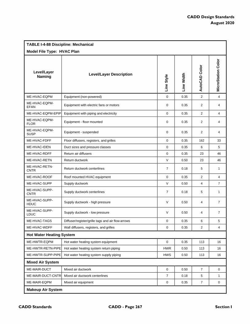
CADD Standards CADD - Page 267 Section I
CADD Design Standards
August 2020
TABLE I-4-88 Discipline: Mechanical
Model File Type: HVAC Plan
Level/Layer
Naming
Level/Layer Description
Lin
e S
tyle
Lin
e W
idth
Au
toC
AD
Co
lor
Mic
roS
tati
on
Co
lor
ME-HVAC-EQPM Equipment (non-powered) 0 0.35 2 4
ME-HVAC-EQPM- EFAN
Equipment with electric fans or motors
0
0.35
2
4
ME-HVAC-EQPM-EPIP Equipment with piping and electricity 0 0.35 2 4
ME-HVAC-EQPM- FLOR
Equipment - floor mounted
0
0.35
2
4
ME-HVAC-EQPM- SUSP
Equipment - suspended
0
0.35
2
4
ME-HVAC-FDFF Floor diffusers, registers, and grilles 0 0.35 162 33
ME-HVAC-IDEN Duct sizes and pressure classes 0 0.35 6 5
ME-HVAC-RDFF Return air diffusers 0 0.35 23 46
ME-HVAC-RETN Return ductwork V 0.50 23 46
ME-HVAC-RETN- CNTR
Return ductwork centerlines
7
0.18
5
1
ME-HVAC-ROOF Roof mounted HVAC equipment 0 0.35 2 4
ME-HVAC-SUPP Supply ductwork V 0.50 4 7
ME-HVAC-SUPP- CNTR
Supply ductwork centerlines
7
0.18
5
1
ME-HVAC-SUPP- HDUC
Supply ductwork - high pressure
V
0.50
4
7
ME-HVAC-SUPP- LDUC
Supply ductwork - low pressure
V
0.50
4
7
ME-HVAC-TAGS Diffuser/register/grille tags and air flow arrows 0 0.35 6 5
ME-HVAC-WDFF Wall diffusers, registers, and grilles 0 0.35 2 4
Hot Water Heating System
ME-HWTR-EQPM Hot water heating system equipment 0 0.35 113 16
ME-HWTR-RETN-PIPE Hot water heating system return piping HWR 0.50 113 16
ME-HWTR-SUPP-PIPE Hot water heating system supply piping HWS 0.50 113 16
Mixed Air System
ME-MAIR-DUCT Mixed air ductwork 0 0.50 7 0
ME-MAIR-DUCT-CNTR Mixed air ductwork centerlines 7 0.18 5 1
ME-MAIR-EQPM Mixed air equipment 0 0.35 7 0
Makeup Air System
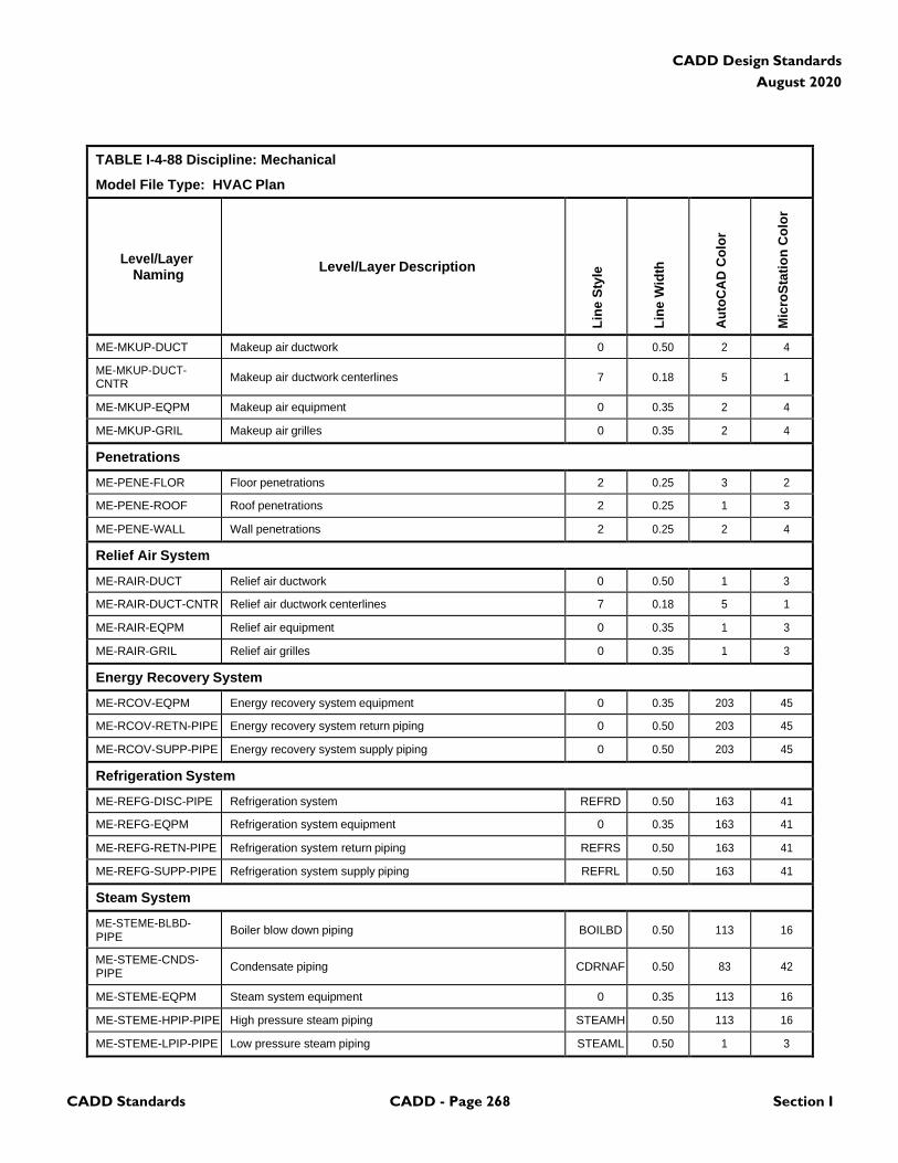
CADD Standards CADD - Page 268 Section I
CADD Design Standards
August 2020
TABLE I-4-88 Discipline: Mechanical
Model File Type: HVAC Plan
Level/Layer
Naming
Level/Layer Description
Lin
e S
tyle
Lin
e W
idth
Au
toC
AD
Co
lor
Mic
roS
tati
on
Co
lor
ME-MKUP-DUCT Makeup air ductwork 0 0.50 2 4
ME-MKUP-DUCT- CNTR
Makeup air ductwork centerlines
7
0.18
5
1
ME-MKUP-EQPM Makeup air equipment 0 0.35 2 4
ME-MKUP-GRIL Makeup air grilles 0 0.35 2 4
Penetrations
ME-PENE-FLOR Floor penetrations 2 0.25 3 2
ME-PENE-ROOF Roof penetrations 2 0.25 1 3
ME-PENE-WALL Wall penetrations 2 0.25 2 4
Relief Air System
ME-RAIR-DUCT Relief air ductwork 0 0.50 1 3
ME-RAIR-DUCT-CNTR Relief air ductwork centerlines 7 0.18 5 1
ME-RAIR-EQPM Relief air equipment 0 0.35 1 3
ME-RAIR-GRIL Relief air grilles 0 0.35 1 3
Energy Recovery System
ME-RCOV-EQPM Energy recovery system equipment 0 0.35 203 45
ME-RCOV-RETN-PIPE Energy recovery system return piping 0 0.50 203 45
ME-RCOV-SUPP-PIPE Energy recovery system supply piping 0 0.50 203 45
Refrigeration System
ME-REFG-DISC-PIPE Refrigeration system REFRD 0.50 163 41
ME-REFG-EQPM Refrigeration system equipment 0 0.35 163 41
ME-REFG-RETN-PIPE Refrigeration system return piping REFRS 0.50 163 41
ME-REFG-SUPP-PIPE Refrigeration system supply piping REFRL 0.50 163 41
Steam System
ME-STEME-BLBD- PIPE
Boiler blow down piping
BOILBD
0.50
113
16
ME-STEME-CNDS- PIPE
Condensate piping
CDRNAF
0.50
83
42
ME-STEME-EQPM Steam system equipment 0 0.35 113 16
ME-STEME-HPIP-PIPE High pressure steam piping STEAMH 0.50 113 16
ME-STEME-LPIP-PIPE Low pressure steam piping STEAML 0.50 1 3
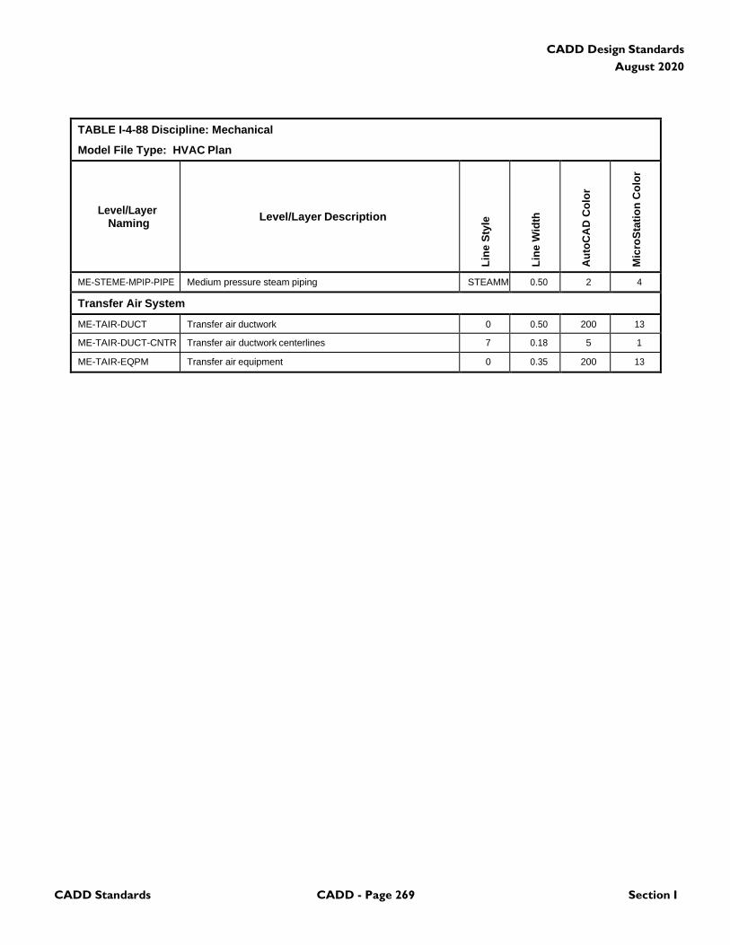
CADD Standards CADD - Page 269 Section I
CADD Design Standards
August 2020
TABLE I-4-88 Discipline: Mechanical
Model File Type: HVAC Plan
Level/Layer
Naming
Level/Layer Description
Lin
e S
tyle
Lin
e W
idth
Au
toC
AD
Co
lor
Mic
roS
tati
on
Co
lor
ME-STEME-MPIP-PIPE Medium pressure steam piping STEAMM 0.50 2 4
Transfer Air System
ME-TAIR-DUCT Transfer air ductwork 0 0.50 200 13
ME-TAIR-DUCT-CNTR Transfer air ductwork centerlines 7 0.18 5 1
ME-TAIR-EQPM Transfer air equipment 0 0.35 200 13
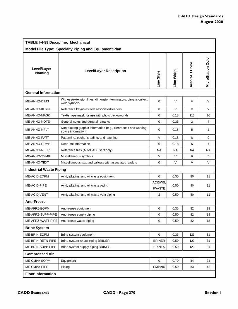
CADD Standards CADD - Page 270 Section I
CADD Design Standards
August 2020
TABLE I-4-89 Discipline: Mechanical
Model File Type: Specialty Piping and Equipment Plan
Level/Layer
Naming
Level/Layer Description
Lin
e S
tyle
Lin
e W
idth
Au
toC
AD
Co
lor
Mic
roS
tati
on
Co
lor
General Information
ME-ANNO-DIMS Witness/extension lines, dimension terminators, dimension text, weld symbols
0
V
V
V
ME-ANNO-KEYN Reference keynotes with associated leaders 0 V V V
ME-ANNO-MASK Text/shape mask for use with photo backgrounds 0 0.18 113 16
ME-ANNO-NOTE General notes and general remarks 0 0.35 2 4
ME-ANNO-NPLT Non-plotting graphic information (e.g., clearances and working space information)
0
0.18
5
1
ME-ANNO-PATT Patterning, poche, shading, and hatching V 0.18 8 9
ME-ANNO-RDME Read-me information 0 0.18 5 1
ME-ANNO-REFR Reference files (AutoCAD users only) NA NA NA NA
ME-ANNO-SYMB Miscellaneous symbols V V 6 5
ME-ANNO-TEXT Miscellaneous text and callouts with associated leaders 0 V V V
Industrial Waste Piping
ME-ACID-EQPM Acid, alkaline, and oil waste equipment 0 0.35 80 11
ME-ACID-PIPE
Acid, alkaline, and oil waste piping
ACIDWS,
IWASTE
0.50
80
11
ME-ACID-VENT Acid, alkaline, and oil waste vent piping 2 0.50 80 11
Anti-Freeze
ME-AFRZ-EQPM Anti-freeze equipment 0 0.35 82 18
ME-AFRZ-SUPP-PIPE Anti-freeze supply piping 0 0.50 82 18
ME-AFRZ-WAST-PIPE Anti-freeze waste piping 0 0.50 82 18
Brine System
ME-BRIN-EQPM Brine system equipment 0 0.35 123 31
ME-BRIN-RETN-PIPE Brine system return piping BRINER BRINER 0.50 123 31
ME-BRIN-SUPP-PIPE Brine system supply piping BRINES BRINES 0.50 123 31
Compressed Air
ME-CMPA-EQPM Equipment 0 0.70 84 34
ME-CMPA-PIPE Piping CMPAIR 0.50 83 42
Floor Information
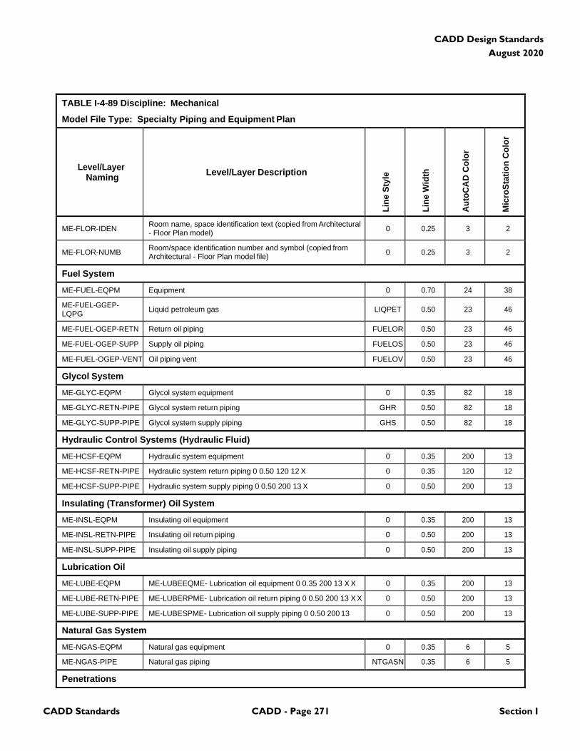
CADD Standards CADD - Page 271 Section I
CADD Design Standards
August 2020
TABLE I-4-89 Discipline: Mechanical
Model File Type: Specialty Piping and Equipment Plan
Level/Layer
Naming
Level/Layer Description
Lin
e S
tyle
Lin
e W
idth
Au
toC
AD
Co
lor
Mic
roS
tati
on
Co
lor
ME-FLOR-IDEN Room name, space identification text (copied from Architectural - Floor Plan model)
0
0.25
3
2
ME-FLOR-NUMB Room/space identification number and symbol (copied from Architectural - Floor Plan model file)
0
0.25
3
2
Fuel System
ME-FUEL-EQPM Equipment 0 0.70 24 38
ME-FUEL-GGEP- LQPG
Liquid petroleum gas
LIQPET
0.50
23
46
ME-FUEL-OGEP-RETN Return oil piping FUELOR 0.50 23 46
ME-FUEL-OGEP-SUPP Supply oil piping FUELOS 0.50 23 46
ME-FUEL-OGEP-VENT Oil piping vent FUELOV 0.50 23 46
Glycol System
ME-GLYC-EQPM Glycol system equipment 0 0.35 82 18
ME-GLYC-RETN-PIPE Glycol system return piping GHR 0.50 82 18
ME-GLYC-SUPP-PIPE Glycol system supply piping GHS 0.50 82 18
Hydraulic Control Systems (Hydraulic Fluid)
ME-HCSF-EQPM Hydraulic system equipment 0 0.35 200 13
ME-HCSF-RETN-PIPE Hydraulic system return piping 0 0.50 120 12 X 0 0.35 120 12
ME-HCSF-SUPP-PIPE Hydraulic system supply piping 0 0.50 200 13 X 0 0.50 200 13
Insulating (Transformer) Oil System
ME-INSL-EQPM Insulating oil equipment 0 0.35 200 13
ME-INSL-RETN-PIPE Insulating oil return piping 0 0.50 200 13
ME-INSL-SUPP-PIPE Insulating oil supply piping 0 0.50 200 13
Lubrication Oil
ME-LUBE-EQPM ME-LUBEEQME- Lubrication oil equipment 0 0.35 200 13 X X 0 0.35 200 13
ME-LUBE-RETN-PIPE ME-LUBERPME- Lubrication oil return piping 0 0.50 200 13 X X 0 0.50 200 13
ME-LUBE-SUPP-PIPE ME-LUBESPME- Lubrication oil supply piping 0 0.50 200 13 0 0.50 200 13
Natural Gas System
ME-NGAS-EQPM Natural gas equipment 0 0.35 6 5
ME-NGAS-PIPE Natural gas piping NTGASN 0.35 6 5
Penetrations
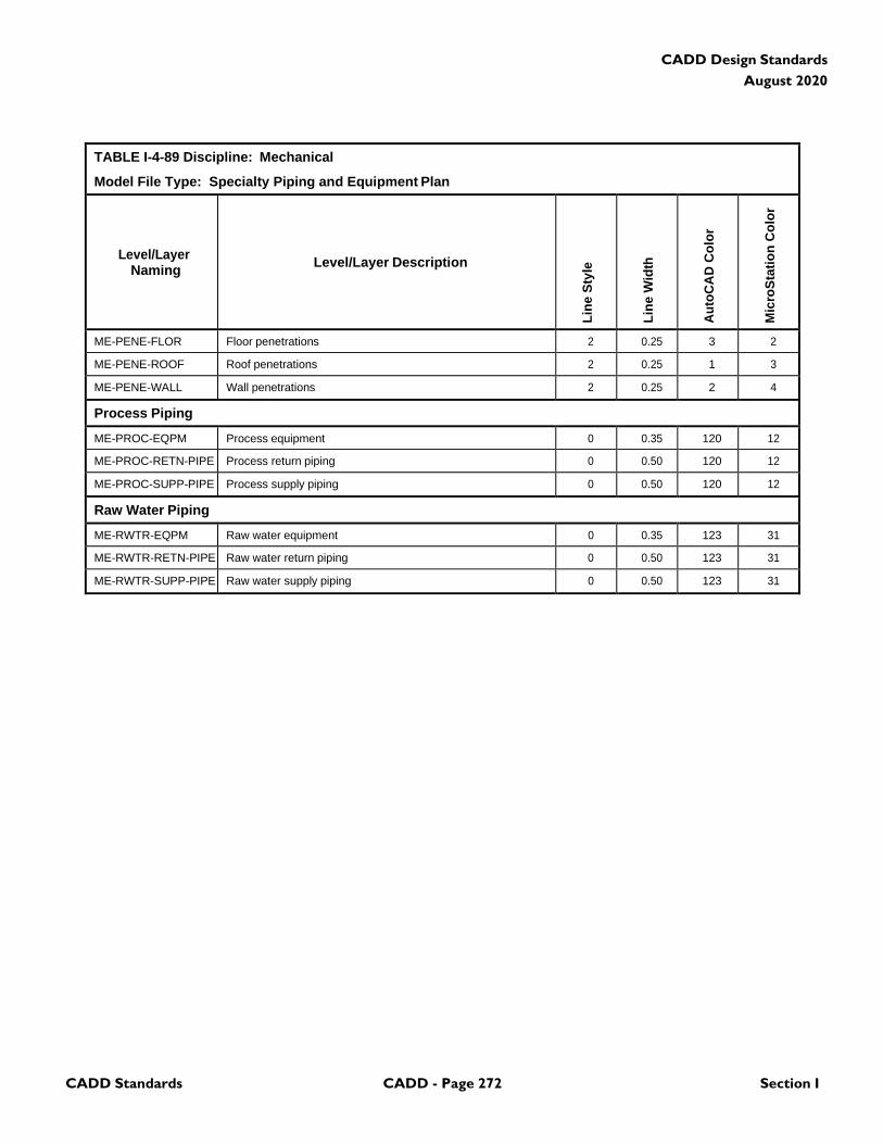
CADD Standards CADD - Page 272 Section I
CADD Design Standards
August 2020
TABLE I-4-89 Discipline: Mechanical
Model File Type: Specialty Piping and Equipment Plan
Level/Layer
Naming
Level/Layer Description
Lin
e S
tyle
Lin
e W
idth
Au
toC
AD
Co
lor
Mic
roS
tati
on
Co
lor
ME-PENE-FLOR Floor penetrations 2 0.25 3 2
ME-PENE-ROOF Roof penetrations 2 0.25 1 3
ME-PENE-WALL Wall penetrations 2 0.25 2 4
Process Piping
ME-PROC-EQPM Process equipment 0 0.35 120 12
ME-PROC-RETN-PIPE Process return piping 0 0.50 120 12
ME-PROC-SUPP-PIPE Process supply piping 0 0.50 120 12
Raw Water Piping
ME-RWTR-EQPM Raw water equipment 0 0.35 123 31
ME-RWTR-RETN-PIPE Raw water return piping 0 0.50 123 31
ME-RWTR-SUPP-PIPE Raw water supply piping 0 0.50 123 31
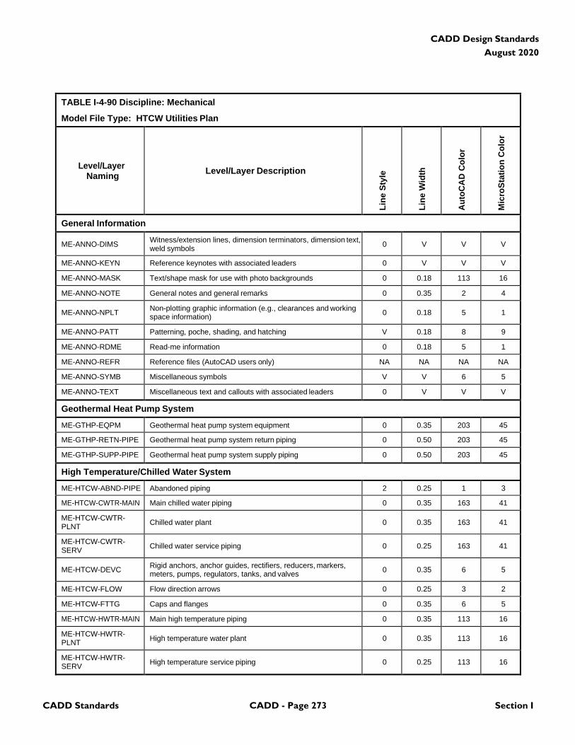
CADD Standards CADD - Page 273 Section I
CADD Design Standards
August 2020
TABLE I-4-90 Discipline: Mechanical
Model File Type: HTCW Utilities Plan
Level/Layer
Naming
Level/Layer Description
Lin
e S
tyle
Lin
e W
idth
Au
toC
AD
Co
lor
Mic
roS
tati
on
Co
lor
General Information
ME-ANNO-DIMS Witness/extension lines, dimension terminators, dimension text, weld symbols
0
V
V
V
ME-ANNO-KEYN Reference keynotes with associated leaders 0 V V V
ME-ANNO-MASK Text/shape mask for use with photo backgrounds 0 0.18 113 16
ME-ANNO-NOTE General notes and general remarks 0 0.35 2 4
ME-ANNO-NPLT Non-plotting graphic information (e.g., clearances and working space information)
0
0.18
5
1
ME-ANNO-PATT Patterning, poche, shading, and hatching V 0.18 8 9
ME-ANNO-RDME Read-me information 0 0.18 5 1
ME-ANNO-REFR Reference files (AutoCAD users only) NA NA NA NA
ME-ANNO-SYMB Miscellaneous symbols V V 6 5
ME-ANNO-TEXT Miscellaneous text and callouts with associated leaders 0 V V V
Geothermal Heat Pump System
ME-GTHP-EQPM Geothermal heat pump system equipment 0 0.35 203 45
ME-GTHP-RETN-PIPE Geothermal heat pump system return piping 0 0.50 203 45
ME-GTHP-SUPP-PIPE Geothermal heat pump system supply piping 0 0.50 203 45
High Temperature/Chilled Water System
ME-HTCW-ABND-PIPE Abandoned piping 2 0.25 1 3
ME-HTCW-CWTR-MAIN Main chilled water piping 0 0.35 163 41
ME-HTCW-CWTR- PLNT
Chilled water plant
0
0.35
163
41
ME-HTCW-CWTR- SERV
Chilled water service piping
0
0.25
163
41
ME-HTCW-DEVC Rigid anchors, anchor guides, rectifiers, reducers, markers, meters, pumps, regulators, tanks, and valves
0
0.35
6
5
ME-HTCW-FLOW Flow direction arrows 0 0.25 3 2
ME-HTCW-FTTG Caps and flanges 0 0.35 6 5
ME-HTCW-HWTR-MAIN Main high temperature piping 0 0.35 113 16
ME-HTCW-HWTR- PLNT
High temperature water plant
0
0.35
113
16
ME-HTCW-HWTR- SERV
High temperature service piping
0
0.25
113
16
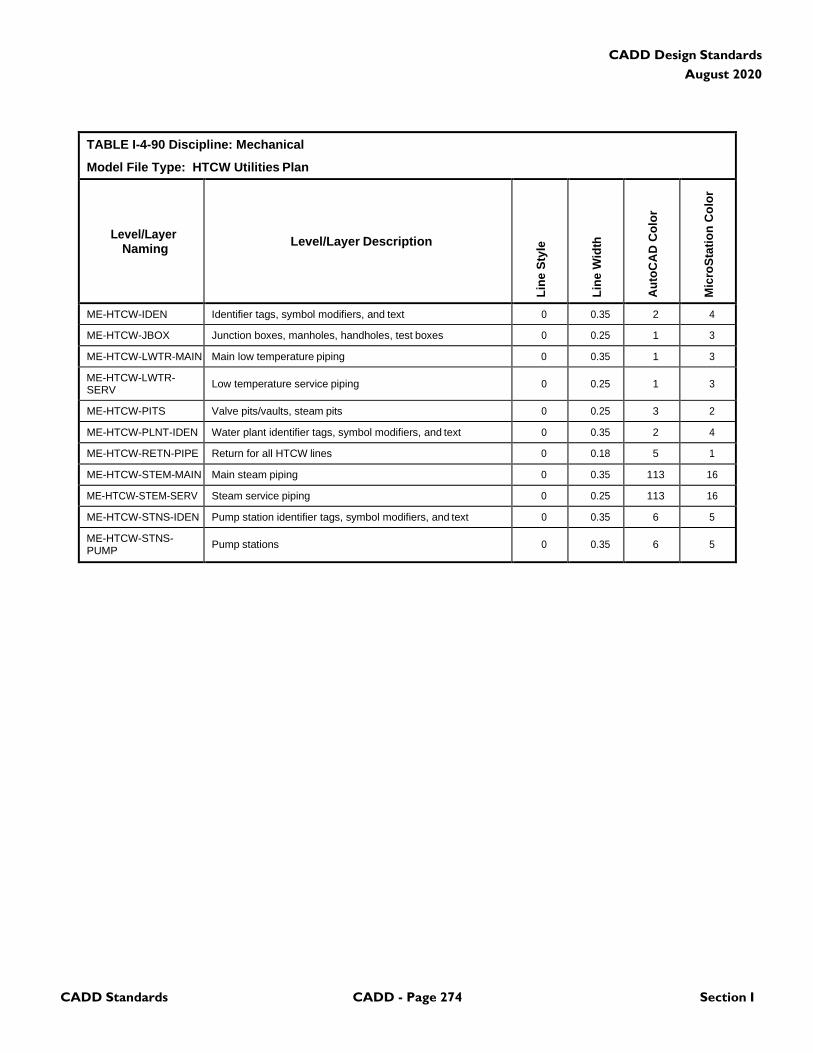
CADD Standards CADD - Page 274 Section I
CADD Design Standards
August 2020
TABLE I-4-90 Discipline: Mechanical
Model File Type: HTCW Utilities Plan
Level/Layer
Naming
Level/Layer Description
Lin
e S
tyle
Lin
e W
idth
Au
toC
AD
Co
lor
Mic
roS
tati
on
Co
lor
ME-HTCW-IDEN Identifier tags, symbol modifiers, and text 0 0.35 2 4
ME-HTCW-JBOX Junction boxes, manholes, handholes, test boxes 0 0.25 1 3
ME-HTCW-LWTR-MAIN Main low temperature piping 0 0.35 1 3
ME-HTCW-LWTR- SERV
Low temperature service piping
0
0.25
1
3
ME-HTCW-PITS Valve pits/vaults, steam pits 0 0.25 3 2
ME-HTCW-PLNT-IDEN Water plant identifier tags, symbol modifiers, and text 0 0.35 2 4
ME-HTCW-RETN-PIPE Return for all HTCW lines 0 0.18 5 1
ME-HTCW-STEM-MAIN Main steam piping 0 0.35 113 16
ME-HTCW-STEM-SERV Steam service piping 0 0.25 113 16
ME-HTCW-STNS-IDEN Pump station identifier tags, symbol modifiers, and text 0 0.35 6 5
ME-HTCW-STNS- PUMP
Pump stations
0
0.35
6
5
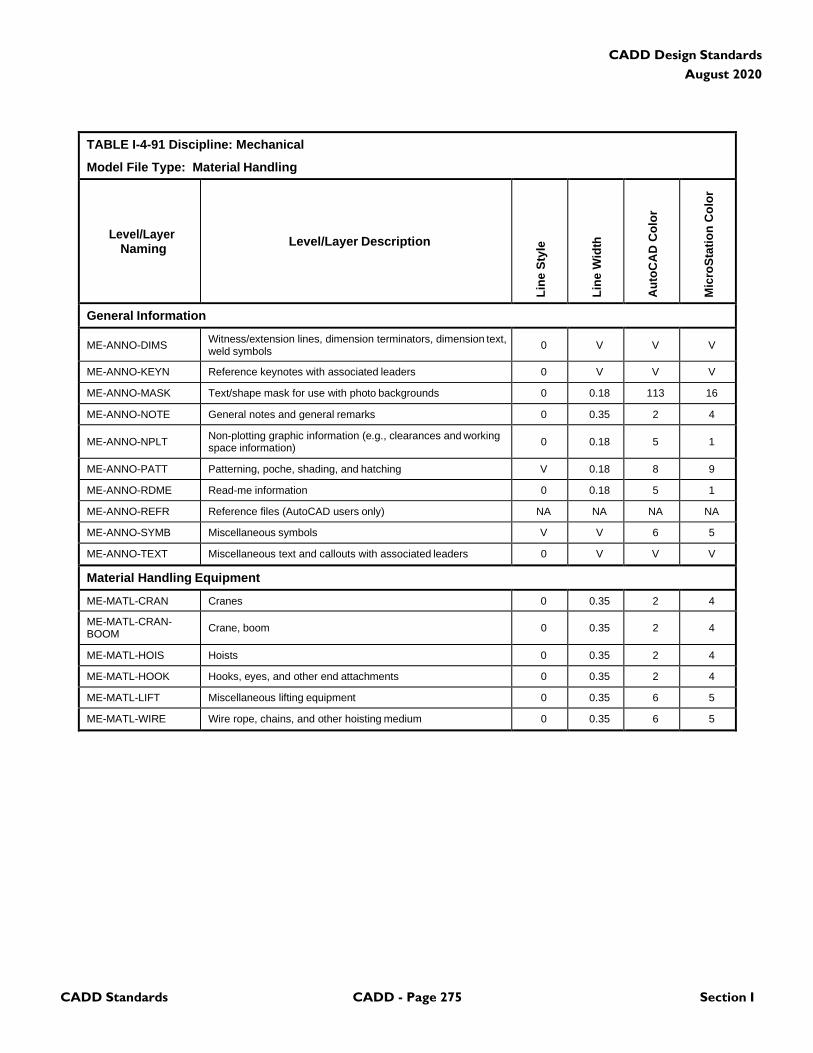
CADD Standards CADD - Page 275 Section I
CADD Design Standards
August 2020
TABLE I-4-91 Discipline: Mechanical
Model File Type: Material Handling
Level/Layer
Naming
Level/Layer Description
Lin
e S
tyle
Lin
e W
idth
Au
toC
AD
Co
lor
Mic
roS
tati
on
Co
lor
General Information
ME-ANNO-DIMS Witness/extension lines, dimension terminators, dimension text, weld symbols
0
V
V
V
ME-ANNO-KEYN Reference keynotes with associated leaders 0 V V V
ME-ANNO-MASK Text/shape mask for use with photo backgrounds 0 0.18 113 16
ME-ANNO-NOTE General notes and general remarks 0 0.35 2 4
ME-ANNO-NPLT Non-plotting graphic information (e.g., clearances and working space information)
0
0.18
5
1
ME-ANNO-PATT Patterning, poche, shading, and hatching V 0.18 8 9
ME-ANNO-RDME Read-me information 0 0.18 5 1
ME-ANNO-REFR Reference files (AutoCAD users only) NA NA NA NA
ME-ANNO-SYMB Miscellaneous symbols V V 6 5
ME-ANNO-TEXT Miscellaneous text and callouts with associated leaders 0 V V V
Material Handling Equipment
ME-MATL-CRAN Cranes 0 0.35 2 4
ME-MATL-CRAN- BOOM
Crane, boom
0
0.35
2
4
ME-MATL-HOIS Hoists 0 0.35 2 4
ME-MATL-HOOK Hooks, eyes, and other end attachments 0 0.35 2 4
ME-MATL-LIFT Miscellaneous lifting equipment 0 0.35 6 5
ME-MATL-WIRE Wire rope, chains, and other hoisting medium 0 0.35 6 5
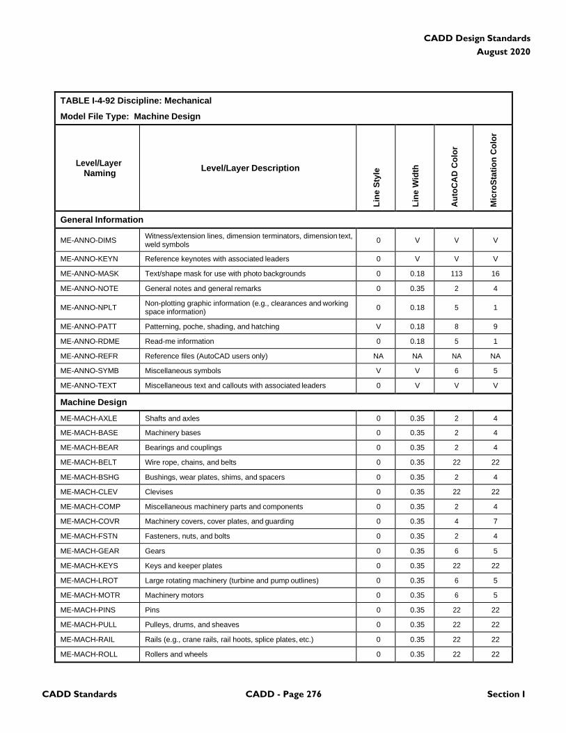
CADD Standards CADD - Page 276 Section I
CADD Design Standards
August 2020
TABLE I-4-92 Discipline: Mechanical
Model File Type: Machine Design
Level/Layer
Naming
Level/Layer Description
Lin
e S
tyle
Lin
e W
idth
Au
toC
AD
Co
lor
Mic
roS
tati
on
Co
lor
General Information
ME-ANNO-DIMS Witness/extension lines, dimension terminators, dimension text, weld symbols
0
V
V
V
ME-ANNO-KEYN Reference keynotes with associated leaders 0 V V V
ME-ANNO-MASK Text/shape mask for use with photo backgrounds 0 0.18 113 16
ME-ANNO-NOTE General notes and general remarks 0 0.35 2 4
ME-ANNO-NPLT Non-plotting graphic information (e.g., clearances and working space information)
0
0.18
5
1
ME-ANNO-PATT Patterning, poche, shading, and hatching V 0.18 8 9
ME-ANNO-RDME Read-me information 0 0.18 5 1
ME-ANNO-REFR Reference files (AutoCAD users only) NA NA NA NA
ME-ANNO-SYMB Miscellaneous symbols V V 6 5
ME-ANNO-TEXT Miscellaneous text and callouts with associated leaders 0 V V V
Machine Design
ME-MACH-AXLE Shafts and axles 0 0.35 2 4
ME-MACH-BASE Machinery bases 0 0.35 2 4
ME-MACH-BEAR Bearings and couplings 0 0.35 2 4
ME-MACH-BELT Wire rope, chains, and belts 0 0.35 22 22
ME-MACH-BSHG Bushings, wear plates, shims, and spacers 0 0.35 2 4
ME-MACH-CLEV Clevises 0 0.35 22 22
ME-MACH-COMP Miscellaneous machinery parts and components 0 0.35 2 4
ME-MACH-COVR Machinery covers, cover plates, and guarding 0 0.35 4 7
ME-MACH-FSTN Fasteners, nuts, and bolts 0 0.35 2 4
ME-MACH-GEAR Gears 0 0.35 6 5
ME-MACH-KEYS Keys and keeper plates 0 0.35 22 22
ME-MACH-LROT Large rotating machinery (turbine and pump outlines) 0 0.35 6 5
ME-MACH-MOTR Machinery motors 0 0.35 6 5
ME-MACH-PINS Pins 0 0.35 22 22
ME-MACH-PULL Pulleys, drums, and sheaves 0 0.35 22 22
ME-MACH-RAIL Rails (e.g., crane rails, rail hoots, splice plates, etc.) 0 0.35 22 22
ME-MACH-ROLL Rollers and wheels 0 0.35 22 22
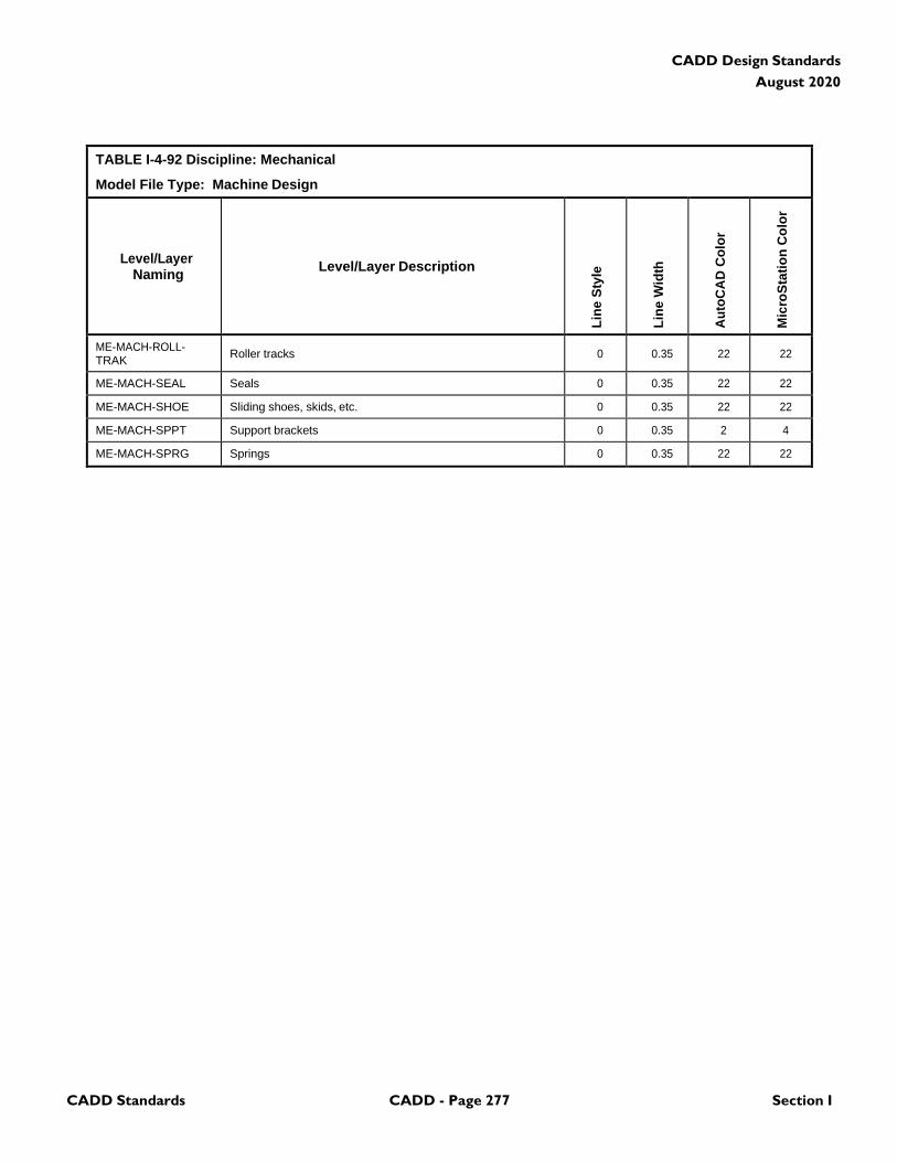
CADD Standards CADD - Page 277 Section I
CADD Design Standards
August 2020
TABLE I-4-92 Discipline: Mechanical
Model File Type: Machine Design
Level/Layer
Naming
Level/Layer Description
Lin
e S
tyle
Lin
e W
idth
Au
toC
AD
Co
lor
Mic
roS
tati
on
Co
lor
ME-MACH-ROLL- TRAK
Roller tracks
0
0.35
22
22
ME-MACH-SEAL Seals 0 0.35 22 22
ME-MACH-SHOE Sliding shoes, skids, etc. 0 0.35 22 22
ME-MACH-SPPT Support brackets 0 0.35 2 4
ME-MACH-SPRG Springs 0 0.35 22 22
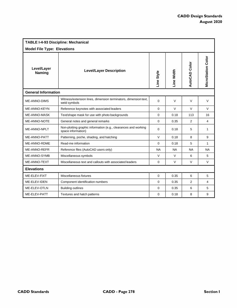
CADD Standards CADD - Page 278 Section I
CADD Design Standards
August 2020
TABLE I-4-93 Discipline: Mechanical
Model File Type: Elevations
Level/Layer
Naming
Level/Layer Description
Lin
e S
tyle
Lin
e W
idth
Au
toC
AD
Co
lor
Mic
roS
tati
on
Co
lor
General Information
ME-ANNO-DIMS Witness/extension lines, dimension terminators, dimension text, weld symbols
0
V
V
V
ME-ANNO-KEYN Reference keynotes with associated leaders 0 V V V
ME-ANNO-MASK Text/shape mask for use with photo backgrounds 0 0.18 113 16
ME-ANNO-NOTE General notes and general remarks 0 0.35 2 4
ME-ANNO-NPLT Non-plotting graphic information (e.g., clearances and working space information)
0
0.18
5
1
ME-ANNO-PATT Patterning, poche, shading, and hatching V 0.18 8 9
ME-ANNO-RDME Read-me information 0 0.18 5 1
ME-ANNO-REFR Reference files (AutoCAD users only) NA NA NA NA
ME-ANNO-SYMB Miscellaneous symbols V V 6 5
ME-ANNO-TEXT Miscellaneous text and callouts with associated leaders 0 V V V
Elevations
ME-ELEV-FIXT Miscellaneous fixtures 0 0.35 6 5
ME-ELEV-IDEN Component identification numbers 0 0.35 2 4
ME-ELEV-OTLN Building outlines 0 0.35 6 5
ME-ELEV-PATT Textures and hatch patterns 0 0.18 8 9
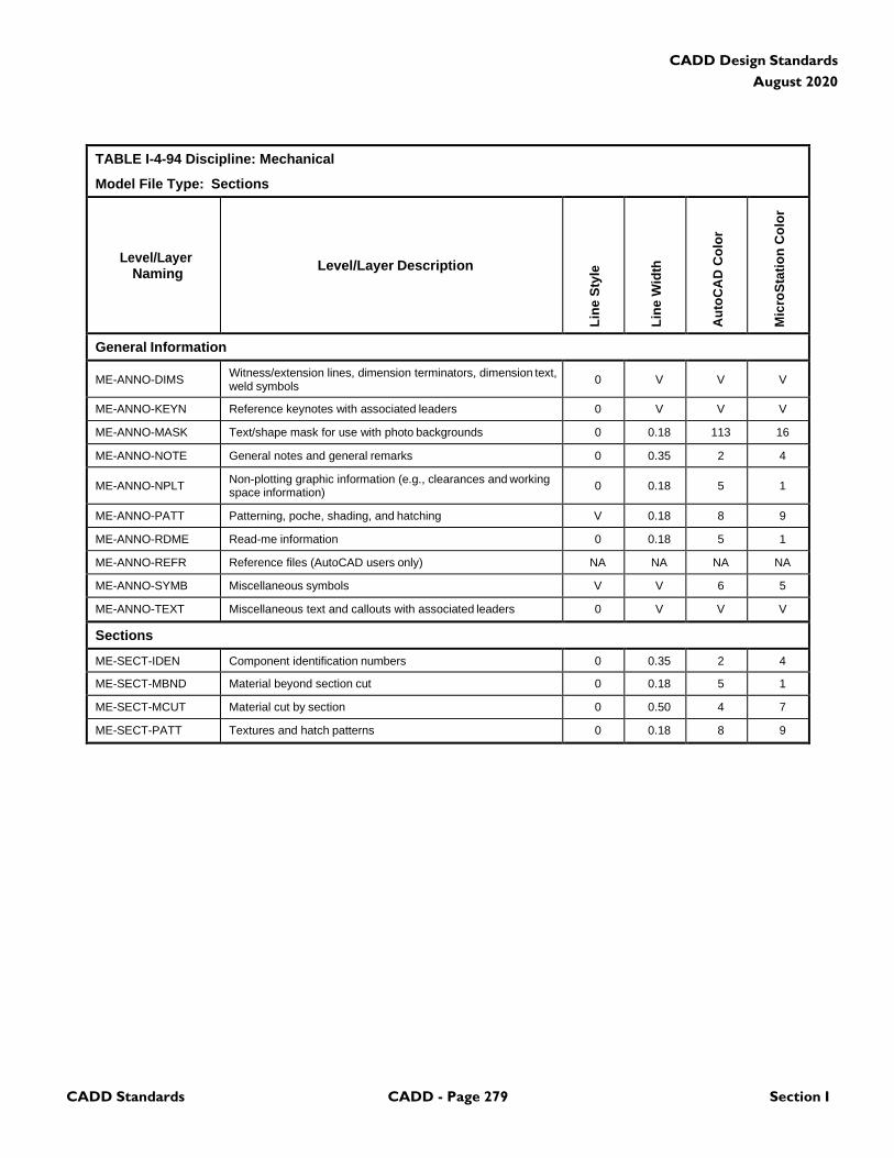
CADD Standards CADD - Page 279 Section I
CADD Design Standards
August 2020
TABLE I-4-94 Discipline: Mechanical
Model File Type: Sections
Level/Layer
Naming
Level/Layer Description
Lin
e S
tyle
Lin
e W
idth
Au
toC
AD
Co
lor
Mic
roS
tati
on
Co
lor
General Information
ME-ANNO-DIMS Witness/extension lines, dimension terminators, dimension text, weld symbols
0
V
V
V
ME-ANNO-KEYN Reference keynotes with associated leaders 0 V V V
ME-ANNO-MASK Text/shape mask for use with photo backgrounds 0 0.18 113 16
ME-ANNO-NOTE General notes and general remarks 0 0.35 2 4
ME-ANNO-NPLT Non-plotting graphic information (e.g., clearances and working space information)
0
0.18
5
1
ME-ANNO-PATT Patterning, poche, shading, and hatching V 0.18 8 9
ME-ANNO-RDME Read-me information 0 0.18 5 1
ME-ANNO-REFR Reference files (AutoCAD users only) NA NA NA NA
ME-ANNO-SYMB Miscellaneous symbols V V 6 5
ME-ANNO-TEXT Miscellaneous text and callouts with associated leaders 0 V V V
Sections
ME-SECT-IDEN Component identification numbers 0 0.35 2 4
ME-SECT-MBND Material beyond section cut 0 0.18 5 1
ME-SECT-MCUT Material cut by section 0 0.50 4 7
ME-SECT-PATT Textures and hatch patterns 0 0.18 8 9
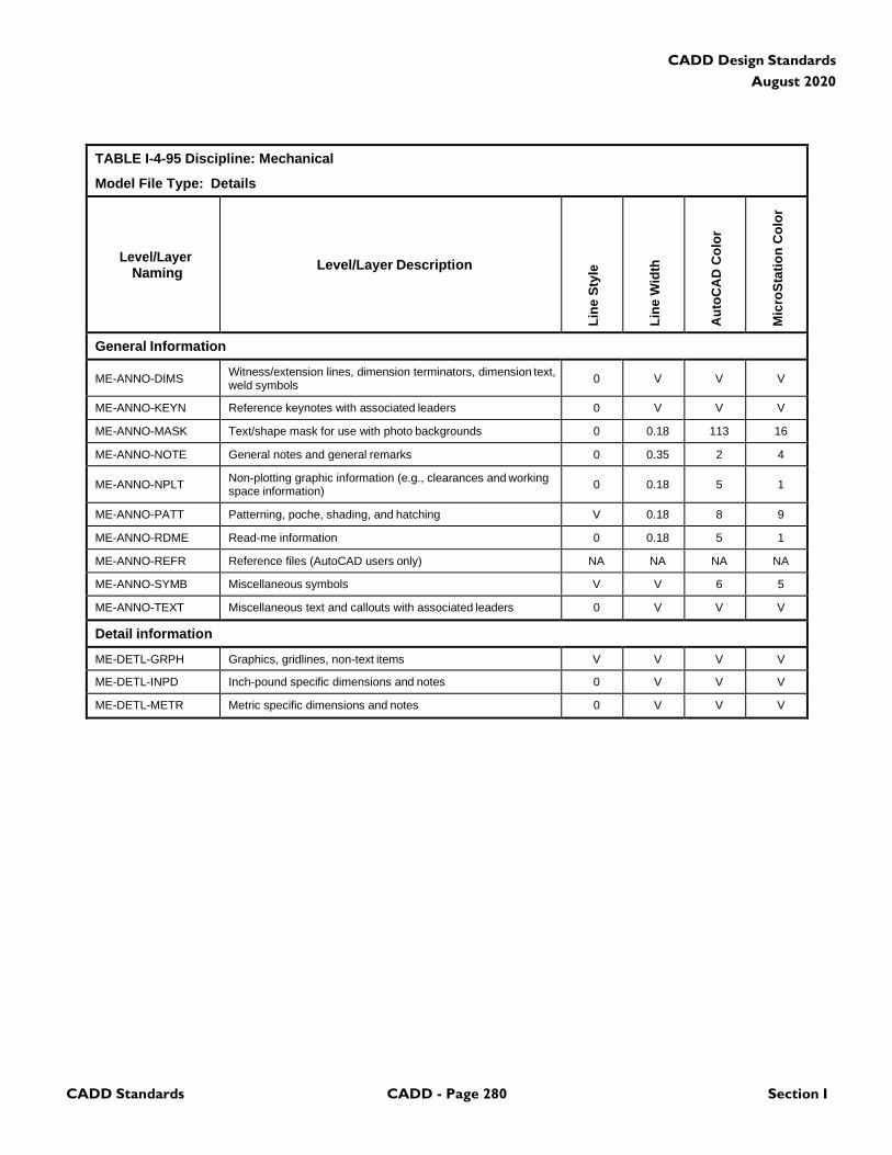
CADD Standards CADD - Page 280 Section I
CADD Design Standards
August 2020
TABLE I-4-95 Discipline: Mechanical
Model File Type: Details
Level/Layer
Naming
Level/Layer Description
Lin
e S
tyle
Lin
e W
idth
Au
toC
AD
Co
lor
Mic
roS
tati
on
Co
lor
General Information
ME-ANNO-DIMS Witness/extension lines, dimension terminators, dimension text, weld symbols
0
V
V
V
ME-ANNO-KEYN Reference keynotes with associated leaders 0 V V V
ME-ANNO-MASK Text/shape mask for use with photo backgrounds 0 0.18 113 16
ME-ANNO-NOTE General notes and general remarks 0 0.35 2 4
ME-ANNO-NPLT Non-plotting graphic information (e.g., clearances and working space information)
0
0.18
5
1
ME-ANNO-PATT Patterning, poche, shading, and hatching V 0.18 8 9
ME-ANNO-RDME Read-me information 0 0.18 5 1
ME-ANNO-REFR Reference files (AutoCAD users only) NA NA NA NA
ME-ANNO-SYMB Miscellaneous symbols V V 6 5
ME-ANNO-TEXT Miscellaneous text and callouts with associated leaders 0 V V V
Detail information
ME-DETL-GRPH Graphics, gridlines, non-text items V V V V
ME-DETL-INPD Inch-pound specific dimensions and notes 0 V V V
ME-DETL-METR Metric specific dimensions and notes 0 V V V
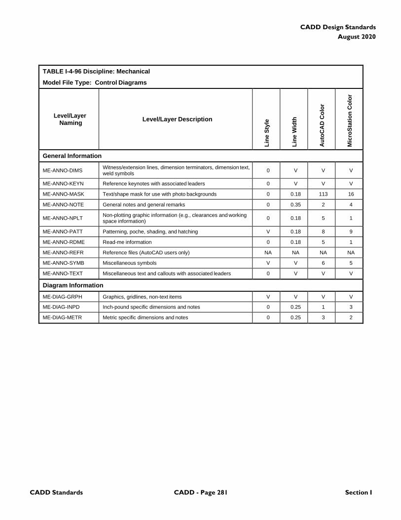
CADD Standards CADD - Page 281 Section I
CADD Design Standards
August 2020
TABLE I-4-96 Discipline: Mechanical
Model File Type: Control Diagrams
Level/Layer
Naming
Level/Layer Description
Lin
e S
tyle
Lin
e W
idth
Au
toC
AD
Co
lor
Mic
roS
tati
on
Co
lor
General Information
ME-ANNO-DIMS Witness/extension lines, dimension terminators, dimension text, weld symbols
0
V
V
V
ME-ANNO-KEYN Reference keynotes with associated leaders 0 V V V
ME-ANNO-MASK Text/shape mask for use with photo backgrounds 0 0.18 113 16
ME-ANNO-NOTE General notes and general remarks 0 0.35 2 4
ME-ANNO-NPLT Non-plotting graphic information (e.g., clearances and working space information)
0
0.18
5
1
ME-ANNO-PATT Patterning, poche, shading, and hatching V 0.18 8 9
ME-ANNO-RDME Read-me information 0 0.18 5 1
ME-ANNO-REFR Reference files (AutoCAD users only) NA NA NA NA
ME-ANNO-SYMB Miscellaneous symbols V V 6 5
ME-ANNO-TEXT Miscellaneous text and callouts with associated leaders 0 V V V
Diagram Information
ME-DIAG-GRPH Graphics, gridlines, non-text items V V V V
ME-DIAG-INPD Inch-pound specific dimensions and notes 0 0.25 1 3
ME-DIAG-METR Metric specific dimensions and notes 0 0.25 3 2
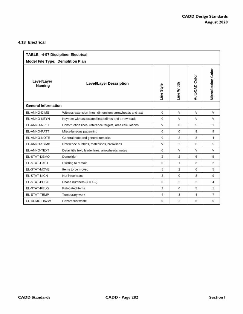
CADD Standards CADD - Page 282 Section I
CADD Design Standards
August 2020
4.18 Electrical
TABLE I-4-97 Discipline: Electrical
Model File Type: Demolition Plan
Level/Layer
Naming
Level/Layer Description
Lin
e S
tyle
Lin
e W
idth
Au
toC
AD
Co
lor
Mic
roS
tati
on
Co
lor
General Information
EL-ANNO-DIMS Witness extension lines, dimensions arrowheads and text 0 V V V
EL-ANNO-KEYN Keynote with associated leaderlines and arrowheads 0 V V V
EL-ANNO-NPLT Construction lines, reference targets, area calculations V 0 5 1
EL-ANNO-PATT Miscellaneous patterning 0 0 8 9
EL-ANNO-NOTE General note and general remarks 0 2 2 4
EL-ANNO-SYMB Reference bubbles, matchlines, breaklines V 2 6 5
EL-ANNO-TEXT Detail title text, leaderlines, arrowheads, notes 0 V V V
EL-STAT-DEMO Demolition 2 2 6 5
EL-STAT-EXST Existing to remain 0 1 3 2
EL-STAT-MOVE Items to be moved 5 2 6 5
EL-STAT-NICN Not in contract 3 0 8 9
EL-STAT-PHS# Phase numbers (# = 1-9) 0 2 2 4
EL-STAT-RELO Relocated items 2 0 5 1
EL-STAT-TEMP Temporary work 4 3 4 7
EL-DEMO-HAZW Hazardous waste 0 2 6 5
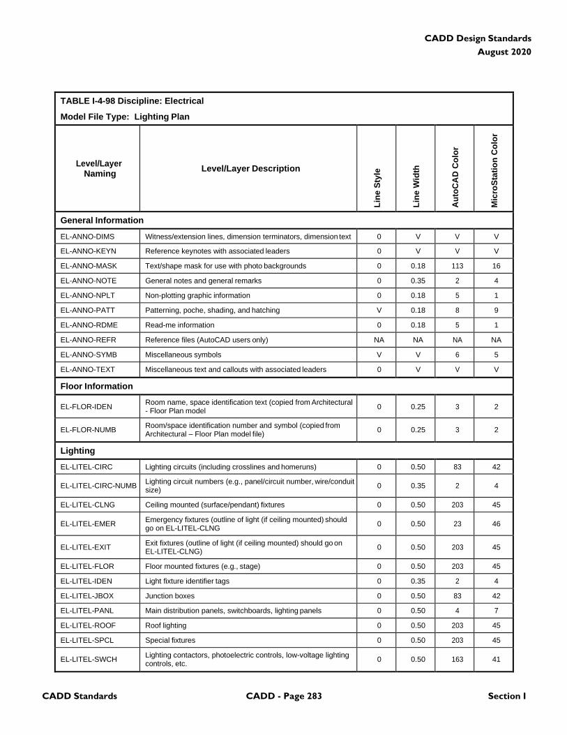
CADD Standards CADD - Page 283 Section I
CADD Design Standards
August 2020
TABLE I-4-98 Discipline: Electrical
Model File Type: Lighting Plan
Level/Layer
Naming
Level/Layer Description
Lin
e S
tyle
Lin
e W
idth
Au
toC
AD
Co
lor
Mic
roS
tati
on
Co
lor
General Information
EL-ANNO-DIMS Witness/extension lines, dimension terminators, dimension text 0 V V V
EL-ANNO-KEYN Reference keynotes with associated leaders 0 V V V
EL-ANNO-MASK Text/shape mask for use with photo backgrounds 0 0.18 113 16
EL-ANNO-NOTE General notes and general remarks 0 0.35 2 4
EL-ANNO-NPLT Non-plotting graphic information 0 0.18 5 1
EL-ANNO-PATT Patterning, poche, shading, and hatching V 0.18 8 9
EL-ANNO-RDME Read-me information 0 0.18 5 1
EL-ANNO-REFR Reference files (AutoCAD users only) NA NA NA NA
EL-ANNO-SYMB Miscellaneous symbols V V 6 5
EL-ANNO-TEXT Miscellaneous text and callouts with associated leaders 0 V V V
Floor Information
EL-FLOR-IDEN Room name, space identification text (copied from Architectural - Floor Plan model
0
0.25
3
2
EL-FLOR-NUMB Room/space identification number and symbol (copied from Architectural – Floor Plan model file)
0
0.25
3
2
Lighting
EL-LITEL-CIRC Lighting circuits (including crosslines and homeruns) 0 0.50 83 42
EL-LITEL-CIRC-NUMB Lighting circuit numbers (e.g., panel/circuit number, wire/conduit size)
0
0.35
2
4
EL-LITEL-CLNG Ceiling mounted (surface/pendant) fixtures 0 0.50 203 45
EL-LITEL-EMER Emergency fixtures (outline of light (if ceiling mounted) should go on EL-LITEL-CLNG
0
0.50
23
46
EL-LITEL-EXIT Exit fixtures (outline of light (if ceiling mounted) should go on EL-LITEL-CLNG)
0
0.50
203
45
EL-LITEL-FLOR Floor mounted fixtures (e.g., stage) 0 0.50 203 45
EL-LITEL-IDEN Light fixture identifier tags 0 0.35 2 4
EL-LITEL-JBOX Junction boxes 0 0.50 83 42
EL-LITEL-PANL Main distribution panels, switchboards, lighting panels 0 0.50 4 7
EL-LITEL-ROOF Roof lighting 0 0.50 203 45
EL-LITEL-SPCL Special fixtures 0 0.50 203 45
EL-LITEL-SWCH Lighting contactors, photoelectric controls, low-voltage lighting controls, etc.
0
0.50
163
41
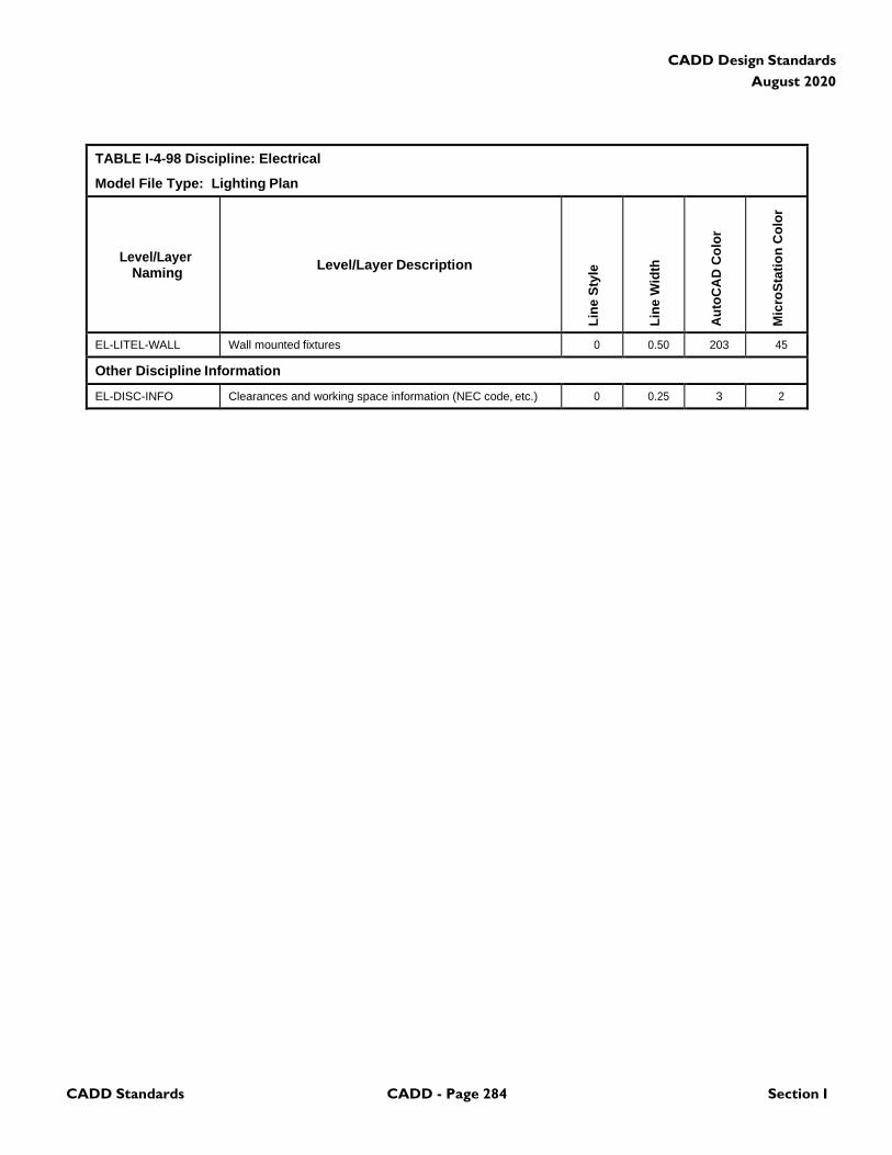
CADD Standards CADD - Page 284 Section I
CADD Design Standards
August 2020
TABLE I-4-98 Discipline: Electrical
Model File Type: Lighting Plan
Level/Layer
Naming
Level/Layer Description
Lin
e S
tyle
Lin
e W
idth
Au
toC
AD
Co
lor
Mic
roS
tati
on
Co
lor
EL-LITEL-WALL Wall mounted fixtures 0 0.50 203 45
Other Discipline Information
EL-DISC-INFO Clearances and working space information (NEC code, etc.) 0 0.25 3 2
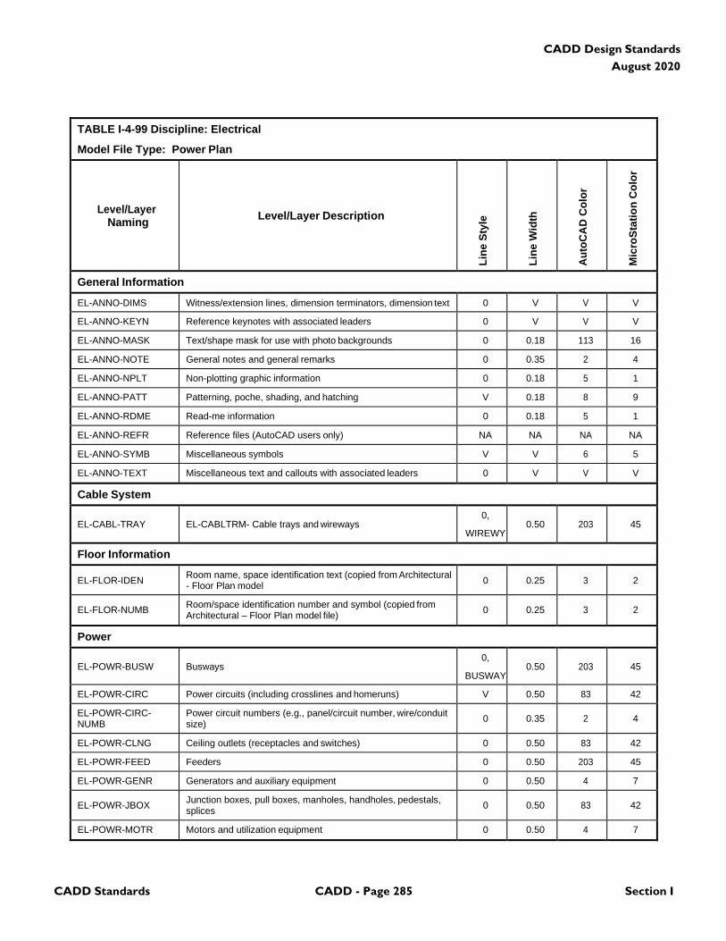
CADD Standards CADD - Page 285 Section I
CADD Design Standards
August 2020
TABLE I-4-99 Discipline: Electrical
Model File Type: Power Plan
Level/Layer
Naming
Level/Layer Description
Lin
e S
tyle
Lin
e W
idth
Au
toC
AD
Co
lor
Mic
roS
tati
on
Co
lor
General Information
EL-ANNO-DIMS Witness/extension lines, dimension terminators, dimension text 0 V V V
EL-ANNO-KEYN Reference keynotes with associated leaders 0 V V V
EL-ANNO-MASK Text/shape mask for use with photo backgrounds 0 0.18 113 16
EL-ANNO-NOTE General notes and general remarks 0 0.35 2 4
EL-ANNO-NPLT Non-plotting graphic information 0 0.18 5 1
EL-ANNO-PATT Patterning, poche, shading, and hatching V 0.18 8 9
EL-ANNO-RDME Read-me information 0 0.18 5 1
EL-ANNO-REFR Reference files (AutoCAD users only) NA NA NA NA
EL-ANNO-SYMB Miscellaneous symbols V V 6 5
EL-ANNO-TEXT Miscellaneous text and callouts with associated leaders 0 V V V
Cable System
EL-CABL-TRAY
EL-CABLTRM- Cable trays and wireways
0,
WIREWY
0.50
203
45
Floor Information
EL-FLOR-IDEN Room name, space identification text (copied from Architectural - Floor Plan model
0
0.25
3
2
EL-FLOR-NUMB Room/space identification number and symbol (copied from Architectural – Floor Plan model file)
0
0.25
3
2
Power
EL-POWR-BUSW
Busways
0,
BUSWAY
0.50
203
45
EL-POWR-CIRC Power circuits (including crosslines and homeruns) V 0.50 83 42
EL-POWR-CIRC- NUMB
Power circuit numbers (e.g., panel/circuit number, wire/conduit size)
0
0.35
2
4
EL-POWR-CLNG Ceiling outlets (receptacles and switches) 0 0.50 83 42
EL-POWR-FEED Feeders 0 0.50 203 45
EL-POWR-GENR Generators and auxiliary equipment 0 0.50 4 7
EL-POWR-JBOX Junction boxes, pull boxes, manholes, handholes, pedestals, splices
0
0.50
83
42
EL-POWR-MOTR Motors and utilization equipment 0 0.50 4 7
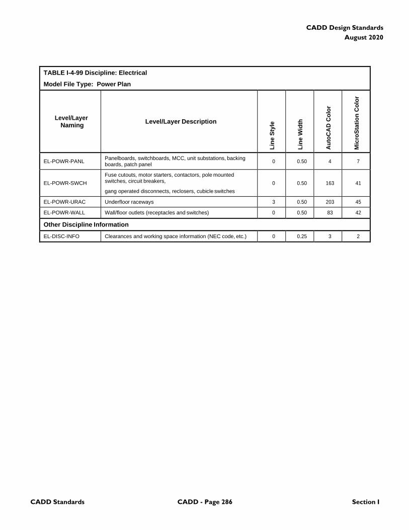
CADD Standards CADD - Page 286 Section I
CADD Design Standards
August 2020
TABLE I-4-99 Discipline: Electrical
Model File Type: Power Plan
Level/Layer
Naming
Level/Layer Description
Lin
e S
tyle
Lin
e W
idth
Au
toC
AD
Co
lor
Mic
roS
tati
on
Co
lor
EL-POWR-PANL Panelboards, switchboards, MCC, unit substations, backing boards, patch panel
0
0.50
4
7
EL-POWR-SWCH
Fuse cutouts, motor starters, contactors, pole mounted switches, circuit breakers,
gang operated disconnects, reclosers, cubicle switches
0
0.50
163
41
EL-POWR-URAC Underfloor raceways 3 0.50 203 45
EL-POWR-WALL Wall/floor outlets (receptacles and switches) 0 0.50 83 42
Other Discipline Information
EL-DISC-INFO Clearances and working space information (NEC code, etc.) 0 0.25 3 2
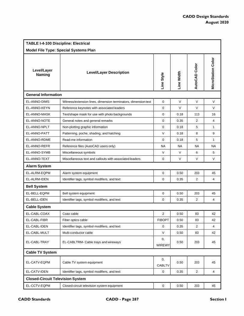
CADD Standards CADD - Page 287 Section I
CADD Design Standards
August 2020
TABLE I-4-100 Discipline: Electrical
Model File Type: Special Systems Plan
Level/Layer
Naming
Level/Layer Description
Lin
e S
tyle
Lin
e W
idth
Au
toC
AD
Co
lor
Mic
roS
tati
on
Co
lor
General Information
EL-ANNO-DIMS Witness/extension lines, dimension terminators, dimension text 0 V V V
EL-ANNO-KEYN Reference keynotes with associated leaders 0 V V V
EL-ANNO-MASK Text/shape mask for use with photo backgrounds 0 0.18 113 16
EL-ANNO-NOTE General notes and general remarks 0 0.35 2 4
EL-ANNO-NPLT Non-plotting graphic information 0 0.18 5 1
EL-ANNO-PATT Patterning, poche, shading, and hatching V 0.18 8 9
EL-ANNO-RDME Read-me information 0 0.18 5 1
EL-ANNO-REFR Reference files (AutoCAD users only) NA NA NA NA
EL-ANNO-SYMB Miscellaneous symbols V V 6 5
EL-ANNO-TEXT Miscellaneous text and callouts with associated leaders 0 V V V
Alarm System
EL-ALRM-EQPM Alarm system equipment 0 0.50 203 45
EL-ALRM-IDEN Identifier tags, symbol modifiers, and text 0 0.35 2 4
Bell System
EL-BELL-EQPM Bell system equipment 0 0.50 203 45
EL-BELL-IDEN Identifier tags, symbol modifiers, and text 0 0.35 2 4
Cable System
EL-CABL-COAX Coax cable 2 0.50 83 42
EL-CABL-FIBR Fiber optics cable FIBOPT 0.50 83 42
EL-CABL-IDEN Identifier tags, symbol modifiers, and text 0 0.35 2 4
EL-CABL-MULT Multi-conductor cable V 0.50 83 42
EL-CABL-TRAY
EL-CABLTRM- Cable trays and wireways
0,
WIREWY
0.50
203
45
Cable TV System
EL-CATV-EQPM
Cable TV system equipment
0,
CABLTV
0.50
203
45
EL-CATV-IDEN Identifier tags, symbol modifiers, and text 0 0.35 2 4
Closed-Circuit Television System
EL-CCTV-EQPM Closed-circuit television system equipment 0 0.50 203 45

CADD Standards CADD - Page 288 Section I
CADD Design Standards
August 2020
TABLE I-4-100 Discipline: Electrical
Model File Type: Special Systems Plan
Level/Layer
Naming
Level/Layer Description
Lin
e S
tyle
Lin
e W
idth
Au
toC
AD
Co
lor
Mic
roS
tati
on
Co
lor
EL-CCTV-IDEN Identifier tags, symbol modifiers, and text 0 0.35 2 4
Clock System
EL-CLOK-EQPM Clock system equipment 0 0.50 203 45
EL-CLOK-IDEN Identifier tags, symbol modifiers, and text 0 0.35 2 4
Central Dictation System
EL-DICT-EQPM Central dictation system equipment 0 0.50 203 45
EL-DICT-IDEN Identifier tags, symbol modifiers, and text 0 0.35 2 4
Energy Monitoring Control Systems
EL-EMCS-EQPM Energy monitoring control system equipment 0 0.50 203 45
EL-EMCS-IDEN Identifier tags, symbol modifiers, and text 0 0.35 2 4
Floor Information
EL-FLOR-IDEN Room name, space identification text (copied from Architectural - Floor Plan model
0
0.25
3
2
EL-FLOR-NUMB Room/space identification number and symbol (copied from Architectural – Floor Plan model file)
0
0.25
3
2
Intercom System
E-INTC-EQPM Intercom system equipment 0 0.50 203 45
E-INTC-IDEN Identifier tags, symbol modifiers, and text 0 0.35 2 4
Nurse Call/ Paging System
EL-NURS-EQPM Nurse call/paging system equipment 0 0.50 203 45
EL-NURS-IDEN Identifier tags, symbol modifiers, and text 0 0.35 2 4
Power
EL-POWR-JBOX Junction boxes, pull boxes, manholes, handholes, pedestals, splices
0
0.50
83
42
EL-POWR-PANL Panelboards, switchboards, MCC, unit substations, backing boards, patch panel
0
0.50
4
7
Security System
EL-SERT-ACCS Access control system 0 0.50 23 46
EL-SERT-CLNG Ceiling mounted sensors 0 0.50 23 46
EL-SERT-FLOR Floor mounted sensors 0 0.50 23 46
EL-SERT-IDEN Identifier tags, symbol modifiers, and text 0 0.35 2 4
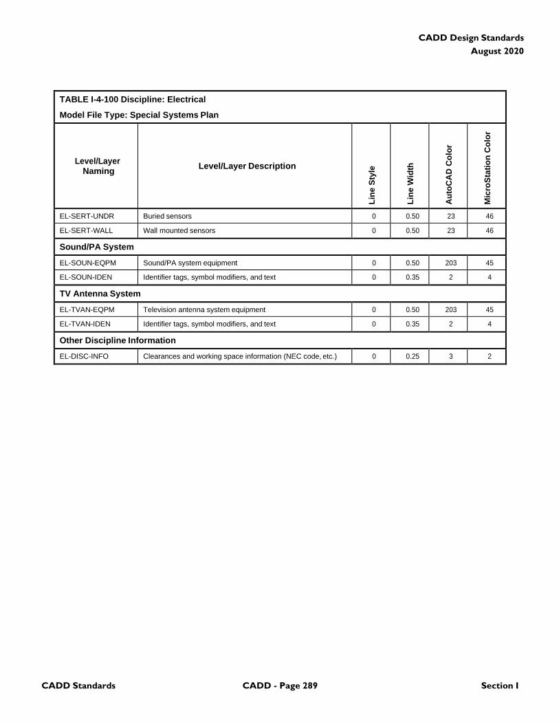
CADD Standards CADD - Page 289 Section I
CADD Design Standards
August 2020
TABLE I-4-100 Discipline: Electrical
Model File Type: Special Systems Plan
Level/Layer
Naming
Level/Layer Description
Lin
e S
tyle
Lin
e W
idth
Au
toC
AD
Co
lor
Mic
roS
tati
on
Co
lor
EL-SERT-UNDR Buried sensors 0 0.50 23 46
EL-SERT-WALL Wall mounted sensors 0 0.50 23 46
Sound/PA System
EL-SOUN-EQPM Sound/PA system equipment 0 0.50 203 45
EL-SOUN-IDEN Identifier tags, symbol modifiers, and text 0 0.35 2 4
TV Antenna System
EL-TVAN-EQPM Television antenna system equipment 0 0.50 203 45
EL-TVAN-IDEN Identifier tags, symbol modifiers, and text 0 0.35 2 4
Other Discipline Information
EL-DISC-INFO Clearances and working space information (NEC code, etc.) 0 0.25 3 2
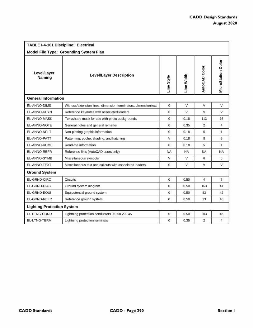
CADD Standards CADD - Page 290 Section I
CADD Design Standards
August 2020
TABLE I-4-101 Discipline: Electrical
Model File Type: Grounding System Plan
Level/Layer
Naming
Level/Layer Description
Lin
e S
tyle
Lin
e W
idth
Au
toC
AD
Co
lor
Mic
roS
tati
on
Co
lor
General Information
EL-ANNO-DIMS Witness/extension lines, dimension terminators, dimension text 0 V V V
EL-ANNO-KEYN Reference keynotes with associated leaders 0 V V V
EL-ANNO-MASK Text/shape mask for use with photo backgrounds 0 0.18 113 16
EL-ANNO-NOTE General notes and general remarks 0 0.35 2 4
EL-ANNO-NPLT Non-plotting graphic information 0 0.18 5 1
EL-ANNO-PATT Patterning, poche, shading, and hatching V 0.18 8 9
EL-ANNO-RDME Read-me information 0 0.18 5 1
EL-ANNO-REFR Reference files (AutoCAD users only) NA NA NA NA
EL-ANNO-SYMB Miscellaneous symbols V V 6 5
EL-ANNO-TEXT Miscellaneous text and callouts with associated leaders 0 V V V
Ground System
EL-GRND-CIRC Circuits 0 0.50 4 7
EL-GRND-DIAG Ground system diagram 0 0.50 163 41
EL-GRND-EQUI Equipotential ground system 0 0.50 83 42
EL-GRND-REFR Reference ground system 0 0.50 23 46
Lighting Protection System
EL-LTNG-COND Lightning protection conductors 0 0.50 203 45 0 0.50 203 45
EL-LTNG-TERM Lightning protection terminals 0 0.35 2 4

CADD Standards CADD - Page 291 Section I
CADD Design Standards
August 2020
TABLE I-4-102 Discipline: Electrical
Model File Type: Electrical Utilities Plan
Level/Layer
Naming
Level/Layer Description
Lin
e S
tyle
Lin
e W
idth
Au
toC
AD
Co
lor
Mic
roS
tati
on
Co
lor
General Information
EL-ANNO-DIMS Witness/extension lines, dimension terminators, dimension text 0 V V V
EL-ANNO-KEYN Reference keynotes with associated leaders 0 V V V
EL-ANNO-MASK Text/shape mask for use with photo backgrounds 0 0.18 113 16
EL-ANNO-NOTE General notes and general remarks 0 0.35 2 4
EL-ANNO-NPLT Non-plotting graphic information 0 0.18 5 1
EL-ANNO-PATT Patterning, poche, shading, and hatching V 0.18 8 9
EL-ANNO-RDME Read-me information 0 0.18 5 1
EL-ANNO-REFR Reference files (AutoCAD users only) NA NA NA NA
EL-ANNO-SYMB Miscellaneous symbols V V 6 5
EL-ANNO-TEXT Miscellaneous text and callouts with associated leaders 0 V V V
Cathodic Protection System
EL-CATH-ANOD Sacrificial anode system 0 0.05 83 42
EL-CATH-CURR Impress current system 0 0.50 83 42
EL-CATH-IDEN Identifier tags, symbol modifier, and text 0 0.35 83 42
EL-CATH-TEST Test stations 0 0.50 83 42
Underground Ductbanks (to be used when multiple systems are in one ductbank system)
EL-DUCT-MULT Ductbank EUDUCN 0.50 83 42
EL-DUCT-MULT-IDEN Identifier tags, symbol modifier and text 0 0.35 83 42
Lighting
EL-LITE-EXTR Exterior lights 0 0.50 203 45
EL-LITE-EXTR-IDEN Exterior light identifier tags, symbol modifiers, and text 0 0.35 203 45
Power
EL-POWR-DEVC Capacitors, voltage regulators, motors, buses, generators, meters, grounds
0
0.50
23
46
EL-POWR-JBOX Junction boxes, pull boxes, manholes, handholes, pedestals, splices
0
0.50
83
42
EL-POWR-POLE Power poles 0 0.50 203 45
EL-POWR-POLE- GUYS
Guying equipment
0
0.50
203
45
EL-POWR-POLE-IDEN Identifier tags, symbol modifiers, and text 0 0.35 203 45
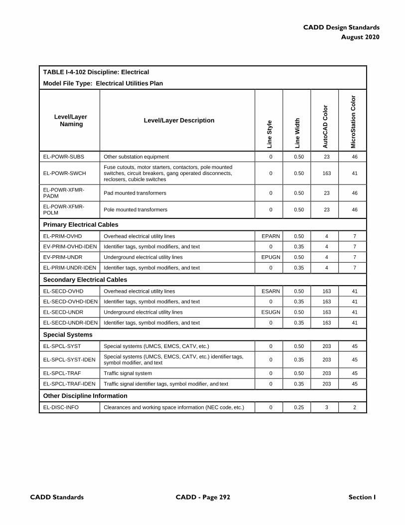
CADD Standards CADD - Page 292 Section I
CADD Design Standards
August 2020
TABLE I-4-102 Discipline: Electrical
Model File Type: Electrical Utilities Plan
Level/Layer
Naming
Level/Layer Description
Lin
e S
tyle
Lin
e W
idth
Au
toC
AD
Co
lor
Mic
roS
tati
on
Co
lor
EL-POWR-SUBS Other substation equipment 0 0.50 23 46
EL-POWR-SWCH
Fuse cutouts, motor starters, contactors, pole mounted switches, circuit breakers, gang operated disconnects, reclosers, cubicle switches
0
0.50
163
41
EL-POWR-XFMR- PADM
Pad mounted transformers
0
0.50
23
46
EL-POWR-XFMR- POLM
Pole mounted transformers
0
0.50
23
46
Primary Electrical Cables
EL-PRIM-OVHD Overhead electrical utility lines EPARN 0.50 4 7
EV-PRIM-OVHD-IDEN Identifier tags, symbol modifiers, and text 0 0.35 4 7
EV-PRIM-UNDR Underground electrical utility lines EPUGN 0.50 4 7
EL-PRIM-UNDR-IDEN Identifier tags, symbol modifiers, and text 0 0.35 4 7
Secondary Electrical Cables
EL-SECD-OVHD Overhead electrical utility lines ESARN 0.50 163 41
EL-SECD-OVHD-IDEN Identifier tags, symbol modifiers, and text 0 0.35 163 41
EL-SECD-UNDR Underground electrical utility lines ESUGN 0.50 163 41
EL-SECD-UNDR-IDEN Identifier tags, symbol modifiers, and text 0 0.35 163 41
Special Systems
EL-SPCL-SYST Special systems (UMCS, EMCS, CATV, etc.) 0 0.50 203 45
EL-SPCL-SYST-IDEN Special systems (UMCS, EMCS, CATV, etc.) identifier tags, symbol modifier, and text
0
0.35
203
45
EL-SPCL-TRAF Traffic signal system 0 0.50 203 45
EL-SPCL-TRAF-IDEN Traffic signal identifier tags, symbol modifier, and text 0 0.35 203 45
Other Discipline Information
EL-DISC-INFO Clearances and working space information (NEC code, etc.) 0 0.25 3 2
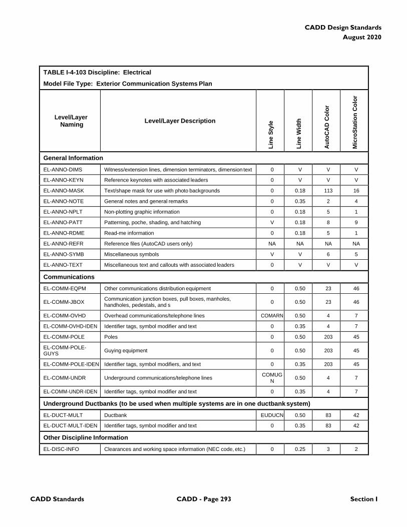
CADD Standards CADD - Page 293 Section I
CADD Design Standards
August 2020
TABLE I-4-103 Discipline: Electrical
Model File Type: Exterior Communication Systems Plan
Level/Layer
Naming
Level/Layer Description
Lin
e S
tyle
Lin
e W
idth
Au
toC
AD
Co
lor
Mic
roS
tati
on
Co
lor
General Information
EL-ANNO-DIMS Witness/extension lines, dimension terminators, dimension text 0 V V V
EL-ANNO-KEYN Reference keynotes with associated leaders 0 V V V
EL-ANNO-MASK Text/shape mask for use with photo backgrounds 0 0.18 113 16
EL-ANNO-NOTE General notes and general remarks 0 0.35 2 4
EL-ANNO-NPLT Non-plotting graphic information 0 0.18 5 1
EL-ANNO-PATT Patterning, poche, shading, and hatching V 0.18 8 9
EL-ANNO-RDME Read-me information 0 0.18 5 1
EL-ANNO-REFR Reference files (AutoCAD users only) NA NA NA NA
EL-ANNO-SYMB Miscellaneous symbols V V 6 5
EL-ANNO-TEXT Miscellaneous text and callouts with associated leaders 0 V V V
Communications
EL-COMM-EQPM Other communications distribution equipment 0 0.50 23 46
EL-COMM-JBOX Communication junction boxes, pull boxes, manholes, handholes, pedestals, and s
0
0.50
23
46
EL-COMM-OVHD Overhead communications/telephone lines COMARN 0.50 4 7
EL-COMM-OVHD-IDEN Identifier tags, symbol modifier and text 0 0.35 4 7
EL-COMM-POLE Poles 0 0.50 203 45
EL-COMM-POLE- GUYS
Guying equipment
0
0.50
203
45
EL-COMM-POLE-IDEN Identifier tags, symbol modifiers, and text 0 0.35 203 45
EL-COMM-UNDR
Underground communications/telephone lines COMUG
N
0.50
4
7
EL-COMM-UNDR-IDEN Identifier tags, symbol modifier and text 0 0.35 4 7
Underground Ductbanks (to be used when multiple systems are in one ductbank system)
EL-DUCT-MULT Ductbank EUDUCN 0.50 83 42
EL-DUCT-MULT-IDEN Identifier tags, symbol modifier and text 0 0.35 83 42
Other Discipline Information
EL-DISC-INFO Clearances and working space information (NEC code, etc.) 0 0.25 3 2

CADD Standards CADD - Page 294 Section I
CADD Design Standards
August 2020
TABLE I-4-104 Discipline: Electrical
Model File Type: Airfield Lighting Plan
Level/Layer
Naming
Level/Layer Description
Lin
e S
tyle
Lin
e W
idth
Au
toC
AD
Co
lor
Mic
roS
tati
on
Co
lor
General Information
EL-ANNO-DIMS Witness/extension lines, dimension terminators, dimension text 0 V V V
EL-ANNO-KEYN Reference keynotes with associated leaders 0 V V V
EL-ANNO-MASK Text/shape mask for use with photo backgrounds 0 0.18 113 16
EL-ANNO-NOTE General notes and general remarks 0 0.35 2 4
EL-ANNO-NPLT Non-plotting graphic information 0 0.18 5 1
EL-ANNO-PATT Patterning, poche, shading, and hatching V 0.18 8 9
EL-ANNO-RDME Read-me information 0 0.18 5 1
EL-ANNO-REFR Reference files (AutoCAD users only) NA NA NA NA
EL-ANNO-SYMB Miscellaneous symbols V V 6 5
EL-ANNO-TEXT Miscellaneous text and callouts with associated leaders 0 V V V
Airfields
EL-AFLD-BCNS-IDEN Identifier tags, symbol modifiers, and text 0 0.35 203 45
EL-AFLD-BCNS-MISC Miscellaneous navaids - windcones and beacons 0 0.50 203 45
EL-AFLD-BCNS-STRB Strobe beacons 0 0.50 203 45
EL-AFLD-CIRC-CTRL Control and monitoring circuits 0 0.50 163 41
EL-AFLD-CIRC-IDEN Circuit identifier tags, symbol modifier, and text 0 0.35 2 4
EL-AFLD-CIRC-MULT Multiple circuits 0 0.50 23 46
EL-AFLD-CIRC-SERS Series circuits 0 0.50 203 45
EL-AFLD-DEVC Capacitors, voltage regulators, motors, buses, generators, meters, grounds
0
0.50
23
46
EL-AFLD-DUCT Ductbanks EUDUCN 0 0.50 83 42
EL-AFLD-JBOX Junction boxes, pull boxes, manholes, handholes, pedestals, splices
0
0.50
23
46
EL-AFLD-LITE-APPR Approach lights 0 0.50 203 45
EL-AFLD-LITE-DIST Distance and arresting gear markers 0 0.50 203 45
EL-AFLD-LITE-LANE Hoverlane, taxilane, and helipad lights 0 0.50 203 45
EL-AFLD-LITE-OBST Obstruction lights 0 0.50 203 45
EL-AFLD-LITE-RUNW Runway lights 0 0.50 203 45
EL-AFLD-LITE-SIGN Taxiway guidance signs 0 0.50 203 45
EL-AFLD-LITE-TAXI Taxiway lights 0 0.50 203 45
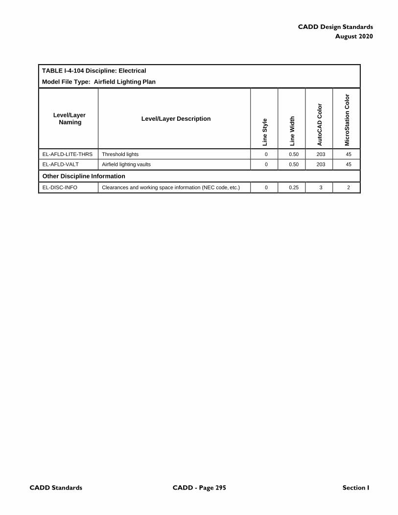
CADD Standards CADD - Page 295 Section I
CADD Design Standards
August 2020
TABLE I-4-104 Discipline: Electrical
Model File Type: Airfield Lighting Plan
Level/Layer
Naming
Level/Layer Description
Lin
e S
tyle
Lin
e W
idth
Au
toC
AD
Co
lor
Mic
roS
tati
on
Co
lor
EL-AFLD-LITE-THRS Threshold lights 0 0.50 203 45
EL-AFLD-VALT Airfield lighting vaults 0 0.50 203 45
Other Discipline Information
EL-DISC-INFO Clearances and working space information (NEC code, etc.) 0 0.25 3 2
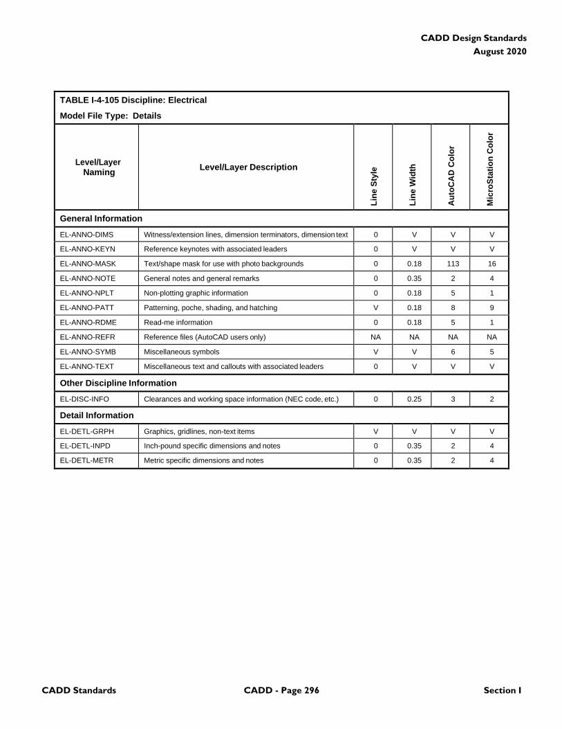
CADD Standards CADD - Page 296 Section I
CADD Design Standards
August 2020
TABLE I-4-105 Discipline: Electrical
Model File Type: Details
Level/Layer
Naming
Level/Layer Description
Lin
e S
tyle
Lin
e W
idth
Au
toC
AD
Co
lor
Mic
roS
tati
on
Co
lor
General Information
EL-ANNO-DIMS Witness/extension lines, dimension terminators, dimension text 0 V V V
EL-ANNO-KEYN Reference keynotes with associated leaders 0 V V V
EL-ANNO-MASK Text/shape mask for use with photo backgrounds 0 0.18 113 16
EL-ANNO-NOTE General notes and general remarks 0 0.35 2 4
EL-ANNO-NPLT Non-plotting graphic information 0 0.18 5 1
EL-ANNO-PATT Patterning, poche, shading, and hatching V 0.18 8 9
EL-ANNO-RDME Read-me information 0 0.18 5 1
EL-ANNO-REFR Reference files (AutoCAD users only) NA NA NA NA
EL-ANNO-SYMB Miscellaneous symbols V V 6 5
EL-ANNO-TEXT Miscellaneous text and callouts with associated leaders 0 V V V
Other Discipline Information
EL-DISC-INFO Clearances and working space information (NEC code, etc.) 0 0.25 3 2
Detail Information
EL-DETL-GRPH Graphics, gridlines, non-text items V V V V
EL-DETL-INPD Inch-pound specific dimensions and notes 0 0.35 2 4
EL-DETL-METR Metric specific dimensions and notes 0 0.35 2 4
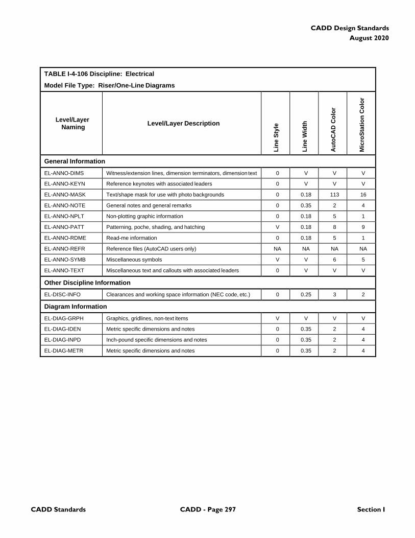
CADD Standards CADD - Page 297 Section I
CADD Design Standards
August 2020
TABLE I-4-106 Discipline: Electrical
Model File Type: Riser/One-Line Diagrams
Level/Layer
Naming
Level/Layer Description
Lin
e S
tyle
Lin
e W
idth
Au
toC
AD
Co
lor
Mic
roS
tati
on
Co
lor
General Information
EL-ANNO-DIMS Witness/extension lines, dimension terminators, dimension text 0 V V V
EL-ANNO-KEYN Reference keynotes with associated leaders 0 V V V
EL-ANNO-MASK Text/shape mask for use with photo backgrounds 0 0.18 113 16
EL-ANNO-NOTE General notes and general remarks 0 0.35 2 4
EL-ANNO-NPLT Non-plotting graphic information 0 0.18 5 1
EL-ANNO-PATT Patterning, poche, shading, and hatching V 0.18 8 9
EL-ANNO-RDME Read-me information 0 0.18 5 1
EL-ANNO-REFR Reference files (AutoCAD users only) NA NA NA NA
EL-ANNO-SYMB Miscellaneous symbols V V 6 5
EL-ANNO-TEXT Miscellaneous text and callouts with associated leaders 0 V V V
Other Discipline Information
EL-DISC-INFO Clearances and working space information (NEC code, etc.) 0 0.25 3 2
Diagram Information
EL-DIAG-GRPH Graphics, gridlines, non-text items V V V V
EL-DIAG-IDEN Metric specific dimensions and notes 0 0.35 2 4
EL-DIAG-INPD Inch-pound specific dimensions and notes 0 0.35 2 4
EL-DIAG-METR Metric specific dimensions and notes 0 0.35 2 4
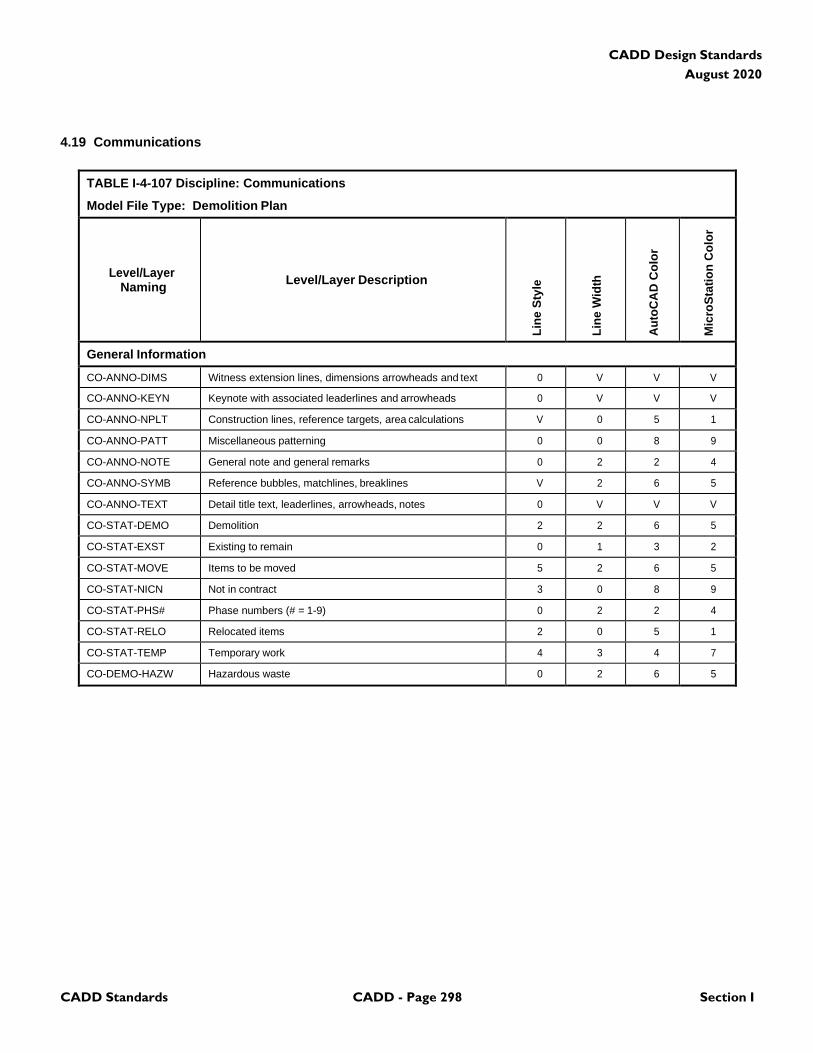
CADD Standards CADD - Page 298 Section I
CADD Design Standards
August 2020
4.19 Communications
TABLE I-4-107 Discipline: Communications
Model File Type: Demolition Plan
Level/Layer
Naming
Level/Layer Description
Lin
e S
tyle
Lin
e W
idth
Au
toC
AD
Co
lor
Mic
roS
tati
on
Co
lor
General Information
CO-ANNO-DIMS Witness extension lines, dimensions arrowheads and text 0 V V V
CO-ANNO-KEYN Keynote with associated leaderlines and arrowheads 0 V V V
CO-ANNO-NPLT Construction lines, reference targets, area calculations V 0 5 1
CO-ANNO-PATT Miscellaneous patterning 0 0 8 9
CO-ANNO-NOTE General note and general remarks 0 2 2 4
CO-ANNO-SYMB Reference bubbles, matchlines, breaklines V 2 6 5
CO-ANNO-TEXT Detail title text, leaderlines, arrowheads, notes 0 V V V
CO-STAT-DEMO Demolition 2 2 6 5
CO-STAT-EXST Existing to remain 0 1 3 2
CO-STAT-MOVE Items to be moved 5 2 6 5
CO-STAT-NICN Not in contract 3 0 8 9
CO-STAT-PHS# Phase numbers (# = 1-9) 0 2 2 4
CO-STAT-RELO Relocated items 2 0 5 1
CO-STAT-TEMP Temporary work 4 3 4 7
CO-DEMO-HAZW Hazardous waste 0 2 6 5
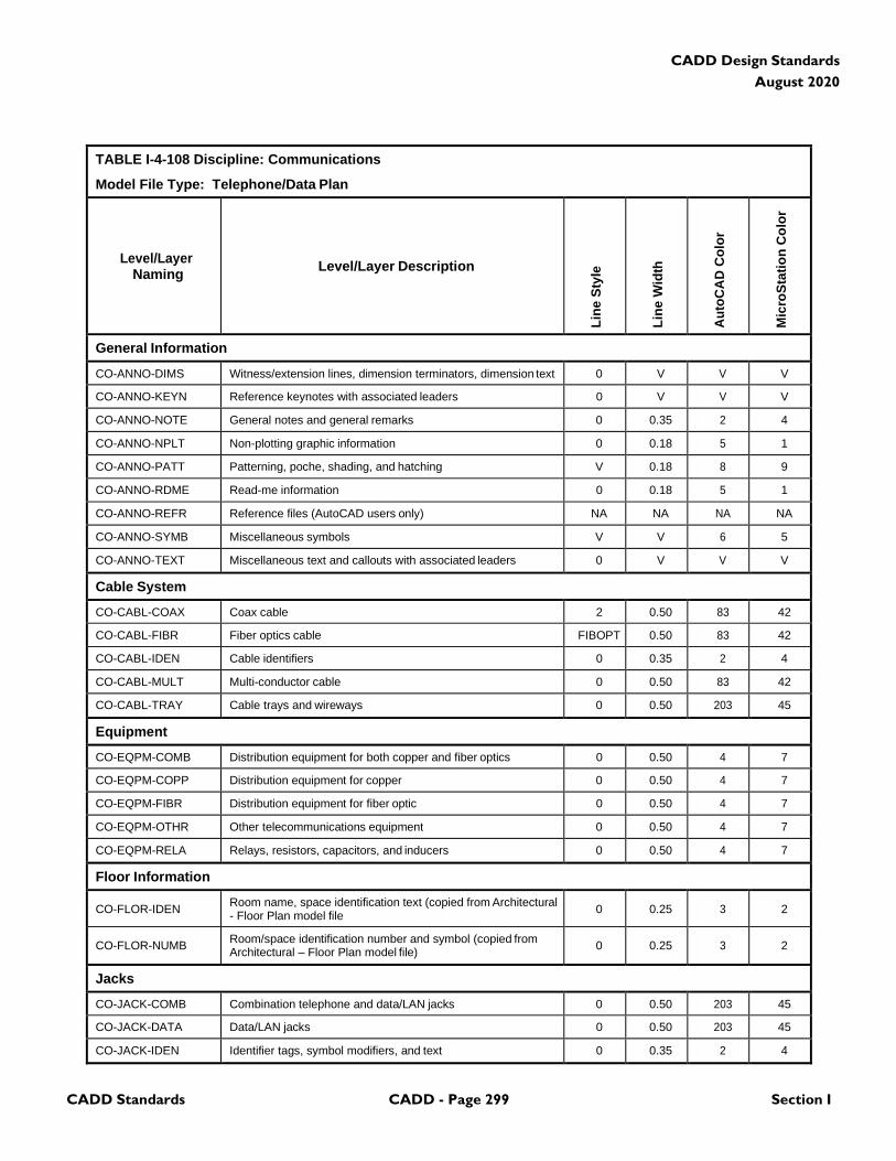
CADD Standards CADD - Page 299 Section I
CADD Design Standards
August 2020
TABLE I-4-108 Discipline: Communications
Model File Type: Telephone/Data Plan
Level/Layer
Naming
Level/Layer Description
Lin
e S
tyle
Lin
e W
idth
Au
toC
AD
Co
lor
Mic
roS
tati
on
Co
lor
General Information
CO-ANNO-DIMS Witness/extension lines, dimension terminators, dimension text 0 V V V
CO-ANNO-KEYN Reference keynotes with associated leaders 0 V V V
CO-ANNO-NOTE General notes and general remarks 0 0.35 2 4
CO-ANNO-NPLT Non-plotting graphic information 0 0.18 5 1
CO-ANNO-PATT Patterning, poche, shading, and hatching V 0.18 8 9
CO-ANNO-RDME Read-me information 0 0.18 5 1
CO-ANNO-REFR Reference files (AutoCAD users only) NA NA NA NA
CO-ANNO-SYMB Miscellaneous symbols V V 6 5
CO-ANNO-TEXT Miscellaneous text and callouts with associated leaders 0 V V V
Cable System
CO-CABL-COAX Coax cable 2 0.50 83 42
CO-CABL-FIBR Fiber optics cable FIBOPT 0.50 83 42
CO-CABL-IDEN Cable identifiers 0 0.35 2 4
CO-CABL-MULT Multi-conductor cable 0 0.50 83 42
CO-CABL-TRAY Cable trays and wireways 0 0.50 203 45
Equipment
CO-EQPM-COMB Distribution equipment for both copper and fiber optics 0 0.50 4 7
CO-EQPM-COPP Distribution equipment for copper 0 0.50 4 7
CO-EQPM-FIBR Distribution equipment for fiber optic 0 0.50 4 7
CO-EQPM-OTHR Other telecommunications equipment 0 0.50 4 7
CO-EQPM-RELA Relays, resistors, capacitors, and inducers 0 0.50 4 7
Floor Information
CO-FLOR-IDEN Room name, space identification text (copied from Architectural - Floor Plan model file
0
0.25
3
2
CO-FLOR-NUMB Room/space identification number and symbol (copied from Architectural – Floor Plan model file)
0
0.25
3
2
Jacks
CO-JACK-COMB Combination telephone and data/LAN jacks 0 0.50 203 45
CO-JACK-DATA Data/LAN jacks 0 0.50 203 45
CO-JACK-IDEN Identifier tags, symbol modifiers, and text 0 0.35 2 4
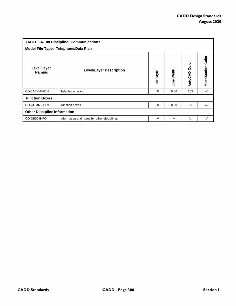
CADD Standards CADD - Page 300 Section I
CADD Design Standards
August 2020
TABLE I-4-108 Discipline: Communications
Model File Type: Telephone/Data Plan
Level/Layer
Naming
Level/Layer Description
Lin
e S
tyle
Lin
e W
idth
Au
toC
AD
Co
lor
Mic
roS
tati
on
Co
lor
CO-JACK-PHON Telephone jacks 0 0.50 203 45
Junction Boxes
CO-COMM-JBOX Junction boxes 0 0.50 83 42
Other Discipline Information
CO-DISC-INFO Information and notes for other disciplines V V V V
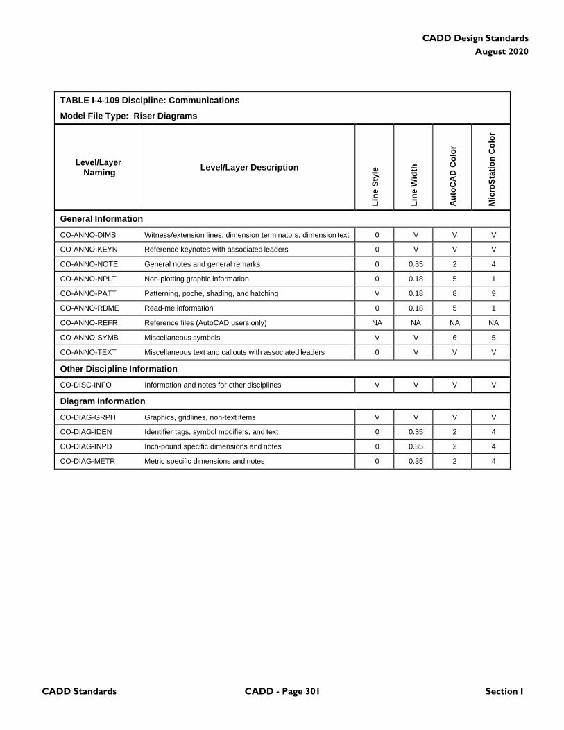
CADD Standards CADD - Page 301 Section I
CADD Design Standards
August 2020
TABLE I-4-109 Discipline: Communications
Model File Type: Riser Diagrams
Level/Layer
Naming
Level/Layer Description
Lin
e S
tyle
Lin
e W
idth
Au
toC
AD
Co
lor
Mic
roS
tati
on
Co
lor
General Information
CO-ANNO-DIMS Witness/extension lines, dimension terminators, dimension text 0 V V V
CO-ANNO-KEYN Reference keynotes with associated leaders 0 V V V
CO-ANNO-NOTE General notes and general remarks 0 0.35 2 4
CO-ANNO-NPLT Non-plotting graphic information 0 0.18 5 1
CO-ANNO-PATT Patterning, poche, shading, and hatching V 0.18 8 9
CO-ANNO-RDME Read-me information 0 0.18 5 1
CO-ANNO-REFR Reference files (AutoCAD users only) NA NA NA NA
CO-ANNO-SYMB Miscellaneous symbols V V 6 5
CO-ANNO-TEXT Miscellaneous text and callouts with associated leaders 0 V V V
Other Discipline Information
CO-DISC-INFO Information and notes for other disciplines V V V V
Diagram Information
CO-DIAG-GRPH Graphics, gridlines, non-text items V V V V
CO-DIAG-IDEN Identifier tags, symbol modifiers, and text 0 0.35 2 4
CO-DIAG-INPD Inch-pound specific dimensions and notes 0 0.35 2 4
CO-DIAG-METR Metric specific dimensions and notes 0 0.35 2 4
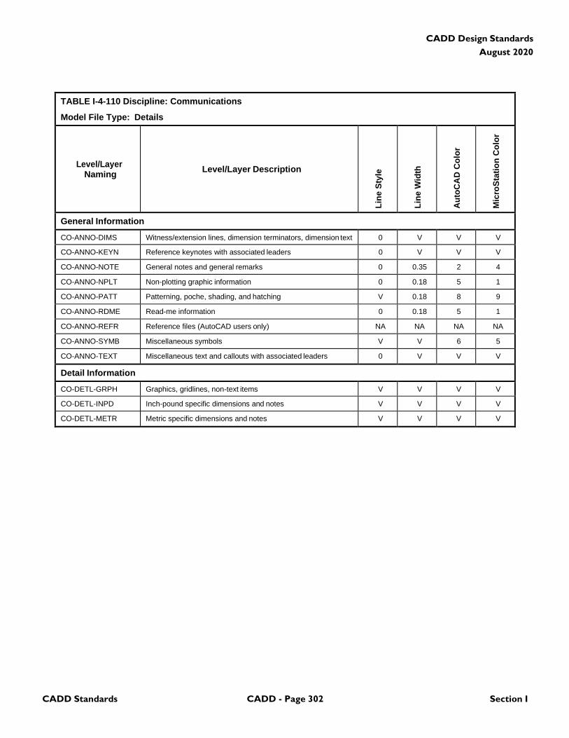
CADD Standards CADD - Page 302 Section I
CADD Design Standards
August 2020
TABLE I-4-110 Discipline: Communications
Model File Type: Details
Level/Layer
Naming
Level/Layer Description
Lin
e S
tyle
Lin
e W
idth
Au
toC
AD
Co
lor
Mic
roS
tati
on
Co
lor
General Information
CO-ANNO-DIMS Witness/extension lines, dimension terminators, dimension text 0 V V V
CO-ANNO-KEYN Reference keynotes with associated leaders 0 V V V
CO-ANNO-NOTE General notes and general remarks 0 0.35 2 4
CO-ANNO-NPLT Non-plotting graphic information 0 0.18 5 1
CO-ANNO-PATT Patterning, poche, shading, and hatching V 0.18 8 9
CO-ANNO-RDME Read-me information 0 0.18 5 1
CO-ANNO-REFR Reference files (AutoCAD users only) NA NA NA NA
CO-ANNO-SYMB Miscellaneous symbols V V 6 5
CO-ANNO-TEXT Miscellaneous text and callouts with associated leaders 0 V V V
Detail Information
CO-DETL-GRPH Graphics, gridlines, non-text items V V V V
CO-DETL-INPD Inch-pound specific dimensions and notes V V V V
CO-DETL-METR Metric specific dimensions and notes V V V V

CADD Standards CADD - Page 303 Section I
CADD Design Standards
August 2020
4.20 Baggage Handling System
TABLE I-4-111 Discipline: Baggage Handling System
Model File Type: Demolition Plan
Level/Layer
Naming
Level/Layer Description
Lin
e S
tyle
Lin
e W
idth
Au
toC
AD
Co
lor
Mic
roS
tati
on
Co
lor
General Information
BG-ANNO-DIMS Witness extension lines, dimensions arrowheads and text 0 V V V
BG-ANNO-KEYN Keynote with associated leaderlines and arrowheads 0 V V V
BG-ANNO-NPLT Construction lines, reference targets, area calculations V 0 5 1
BG-ANNO-PATT Miscellaneous patterning 0 0 8 9
BG-ANNO-NOTE General note and general remarks 0 2 2 4
BG-ANNO-SYMB Reference bubbles, matchlines, breaklines V 2 6 5
BG-ANNO-TEXT Detail title text, leaderlines, arrowheads, notes 0 V V V
BG-STAT-DEMO Demolition 2 2 6 5
BG-STAT-EXST Existing to remain 0 1 3 2
BG-STAT-MOVE Items to be moved 5 2 6 5
BG-STAT-NICN Not in contract 3 0 8 9
BG-STAT-PHS# Phase numbers (# = 1-9) 0 2 2 4
BG-STAT-RELO Relocated items 2 0 5 1
BG-STAT-TEMP Temporary work 4 3 4 7
BG-DEMO-HAZW Hazardous waste 0 2 6 5
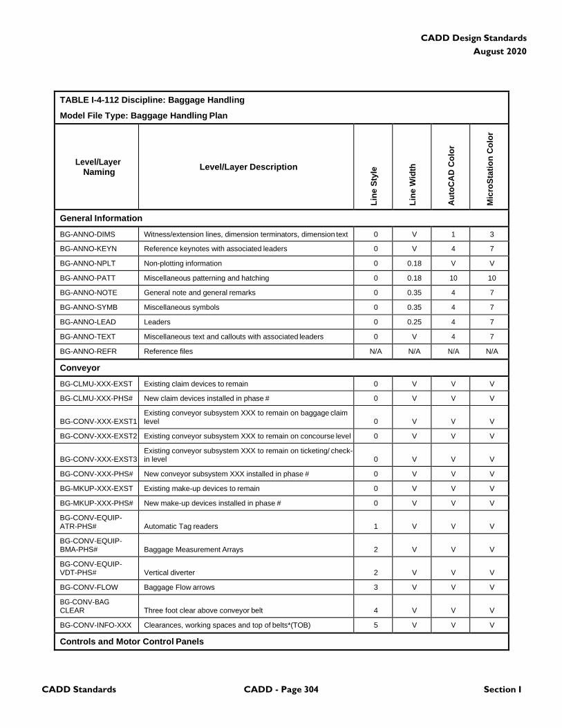
CADD Standards CADD - Page 304 Section I
CADD Design Standards
August 2020
TABLE I-4-112 Discipline: Baggage Handling
Model File Type: Baggage Handling Plan
Level/Layer
Naming
Level/Layer Description
Lin
e S
tyle
Lin
e W
idth
Au
toC
AD
Co
lor
Mic
roS
tati
on
Co
lor
General Information
BG-ANNO-DIMS Witness/extension lines, dimension terminators, dimension text 0 V 1 3
BG-ANNO-KEYN Reference keynotes with associated leaders 0 V 4 7
BG-ANNO-NPLT Non-plotting information 0 0.18 V V
BG-ANNO-PATT Miscellaneous patterning and hatching 0 0.18 10 10
BG-ANNO-NOTE General note and general remarks 0 0.35 4 7
BG-ANNO-SYMB Miscellaneous symbols 0 0.35 4 7
BG-ANNO-LEAD Leaders 0 0.25 4 7
BG-ANNO-TEXT Miscellaneous text and callouts with associated leaders 0 V 4 7
BG-ANNO-REFR Reference files N/A N/A N/A N/A
Conveyor
BG-CLMU-XXX-EXST Existing claim devices to remain 0 V V V
BG-CLMU-XXX-PHS# New claim devices installed in phase # 0 V V V
BG-CONV-XXX-EXST1
Existing conveyor subsystem XXX to remain on baggage claim level
0
V
V
V
BG-CONV-XXX-EXST2 Existing conveyor subsystem XXX to remain on concourse level 0 V V V
BG-CONV-XXX-EXST3
Existing conveyor subsystem XXX to remain on ticketing/ check- in level
0
V
V
V
BG-CONV-XXX-PHS# New conveyor subsystem XXX installed in phase # 0 V V V
BG-MKUP-XXX-EXST Existing make-up devices to remain 0 V V V
BG-MKUP-XXX-PHS# New make-up devices installed in phase # 0 V V V
BG-CONV-EQUIP- ATR-PHS#
Automatic Tag readers
1
V
V
V
BG-CONV-EQUIP- BMA-PHS#
Baggage Measurement Arrays
2
V
V
V
BG-CONV-EQUIP- VDT-PHS#
Vertical diverter
2
V
V
V
BG-CONV-FLOW Baggage Flow arrows 3 V V V
BG-CONV-BAG CLEAR
Three foot clear above conveyor belt
4
V
V
V
BG-CONV-INFO-XXX Clearances, working spaces and top of belts*(TOB) 5 V V V
Controls and Motor Control Panels
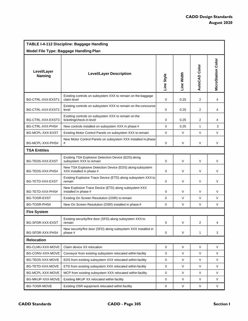
CADD Standards CADD - Page 305 Section I
CADD Design Standards
August 2020
TABLE I-4-112 Discipline: Baggage Handling
Model File Type: Baggage Handling Plan
Level/Layer
Naming
Level/Layer Description
Lin
e S
tyle
Lin
e W
idth
Au
toC
AD
Co
lor
Mic
roS
tati
on
Co
lor
BG-CTRL-XXX-EXST1
Existing controls on subsystem XXX to remain on the baggage claim level
0
0.25
2
4
BG-CTRL-XXX-EXST2
Existing controls on subsystem XXX to remain on the concourse level
0
0.25
2
4
BG-CTRL-XXX-EXST3
Existing controls on subsystem XXX to remain on the ticketing/check-in level
0
0.25
2
4
BG-CTRL-XXX-PHS# New controls installed on subsystem XXX in phase # 0 0.25 1 3
BG-MCPL-XXX-EXST Existing Motor Control Panels on subsystem XXX to remain 0 V V V
BG-MCPL-XXX-PHS#
New Motor Control Panels on subsystem XXX installed in phase #
0
V
V
V
TSA Entities
BG-TEDS-XXX-EXST
Existing TSA Explosive Detection Device (EDS) along subsystem XXX to remain
0
V
V
V
BG-TEDS-XXX-PHS#
New TSA Explosive Detection Device (EDS) along subsystem XXX installed in phase #
0
V
V
V
BG-TETD-XXX-EXST
Existing Explosive Trace Device (ETD) along subsystem XXX to remain
0
V
V
V
BG-TETD-XXX-PHS#
New Explosive Trace Device (ETD) along subsystem XXX installed in phase #
0
V
V
V
BG-TOSR-EXST Existing On Screen Resolution (OSR) to remain 0 V V V
BG-TOSR-PHS# New On Screen Resolution (OSR) installed in phase # 0 V V V
Fire System
BG-SFDR-XXX-EXST
Existing security/fire door (SFD) along subsystem XXX to remain
0
V
2
4
BG-SFDR-XXX-PHS#
New security/fire door (SFD) along subsystem XXX installed in phase #
0
V
1
3
Relocation
BG-CLMU-XXX-MOVE Claim device XX relocation 0 V V V
BG-CONV-XXX-MOVE Conveyor from existing subsystem relocated within facility 0 V V V
BG-TEDS-XXX-MOVE EDS from existing subsystem XXX relocated within facility 0 V V V
BG-TETD-XXX-MOVE ETD from existing subsystem XXX relocated within facility 0 V V V
BG-MCPL-XXX-MOVE MCP from existing subsystem XXX relocated within facility 0 V V V
BG-MKUP-XXX-MOVE Existing MKUP XX relocated within facility 0 V V V
BG-TOSR-MOVE Existing OSR equipment relocated within facility 0 V V V
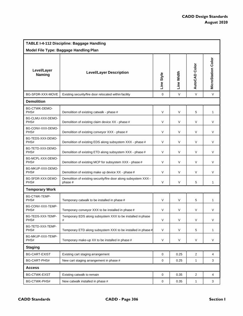
CADD Standards CADD - Page 306 Section I
CADD Design Standards
August 2020
TABLE I-4-112 Discipline: Baggage Handling
Model File Type: Baggage Handling Plan
Level/Layer
Naming
Level/Layer Description
Lin
e S
tyle
Lin
e W
idth
Au
toC
AD
Co
lor
Mic
roS
tati
on
Co
lor
BG-SFDR-XXX-MOVE Existing security/fire door relocated within facility 0 V V V
Demolition
BG-CTWK-DEMO- PHS#
Demolition of existing catwalk - phase #
V
V
5
1
BG-CLMU-XXX-DEMO- PHS#
Demolition of existing claim device XX - phase #
V
V
V
V
BG-CONV-XXX-DEMO- PHS#
Demolition of existing conveyor XXX - phase #
V
V
V
V
BG-TEDS-XXX-DEMO- PHS#
Demolition of existing EDS along subsystem XXX - phase #
V
V
V
V
BG-TETD-XXX-DEMO- PHS#
Demolition of existing ETD along subsystem XXX - phase #
V
V
V
V
BG-MCPL-XXX-DEMO- PHS#
Demolition of existing MCP for subsystem XXX - phase #
V
V
V
V
BG-MKUP-XXX-DEMO- PHS#
Demolition of existing make up device XX - phase #
V
V
V
V
BG-SFDR-XXX-DEMO- PHS#
Demolition of existing security/fire door along subsystem XXX - phase #
V
V
5
1
Temporary Work
BG-CTWK-TEMP- PHS#
Temporary catwalk to be installed in phase #
V
V
5
1
BG-CONV-XXX-TEMP- PHS#
Temporary conveyor XXX to be installed in phase #
V
V
V
V
BG-TEDS-XXX-TEMP- PHS#
Temporary EDS along subsystem XXX to be installed in phase #
V
V
V
V
BG-TETD-XXX-TEMP- PHS#
Temporary ETD along subsystem XXX to be installed in phase #
V
V
5
1
BG-MKUP-XXX-TEMP- PHS#
Temporary make-up XX to be installed in phase #
V
V
V
V
Staging
BG-CART-EXIST Existing cart staging arrangement 0 0.25 2 4
BG-CART-PHS# New cart staging arrangement in phase # 0 0.25 1 3
Access
BG-CTWK-EXST Existing catwalk to remain 0 0.35 2 4
BG-CTWK-PHS# New catwalk installed in phase # 0 0.35 1 3
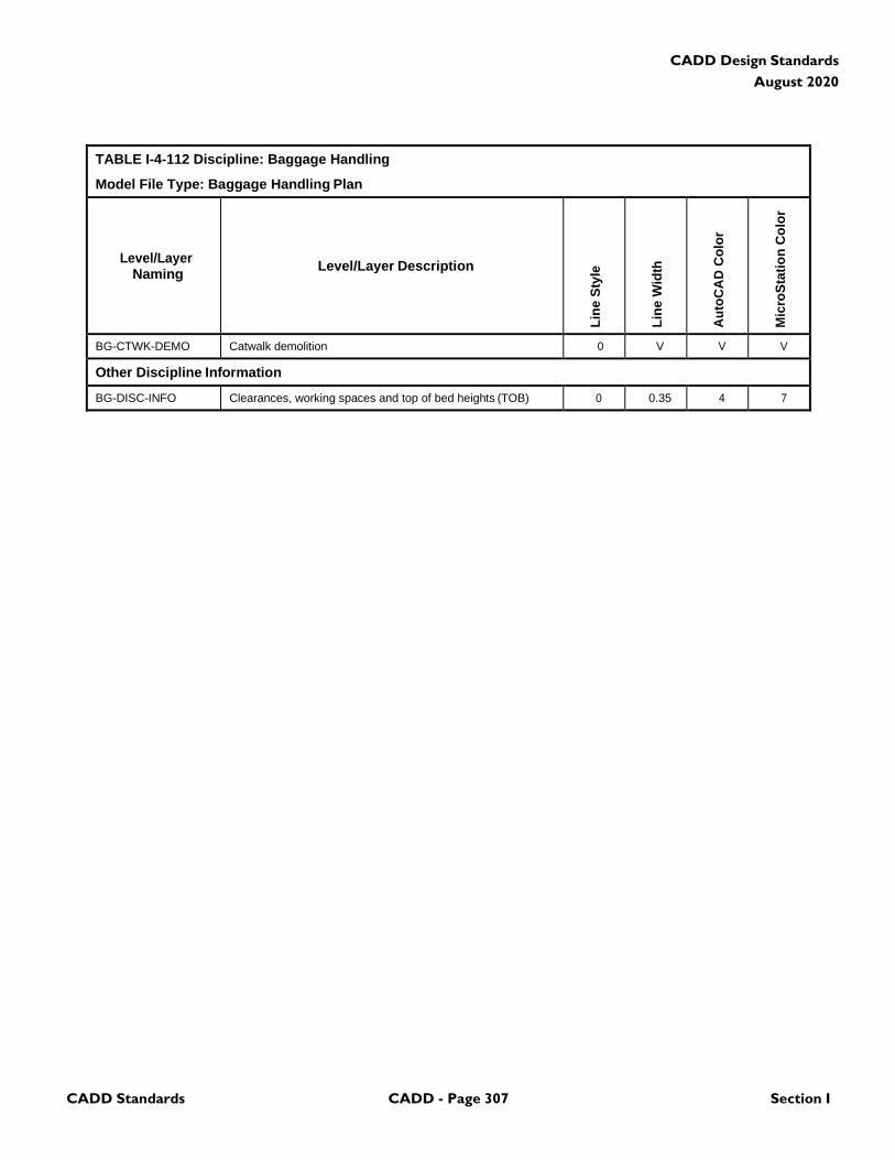
CADD Standards CADD - Page 307 Section I
CADD Design Standards
August 2020
TABLE I-4-112 Discipline: Baggage Handling
Model File Type: Baggage Handling Plan
Level/Layer
Naming
Level/Layer Description
Lin
e S
tyle
Lin
e W
idth
Au
toC
AD
Co
lor
Mic
roS
tati
on
Co
lor
BG-CTWK-DEMO Catwalk demolition 0 V V V
Other Discipline Information
BG-DISC-INFO Clearances, working spaces and top of bed heights (TOB) 0 0.35 4 7
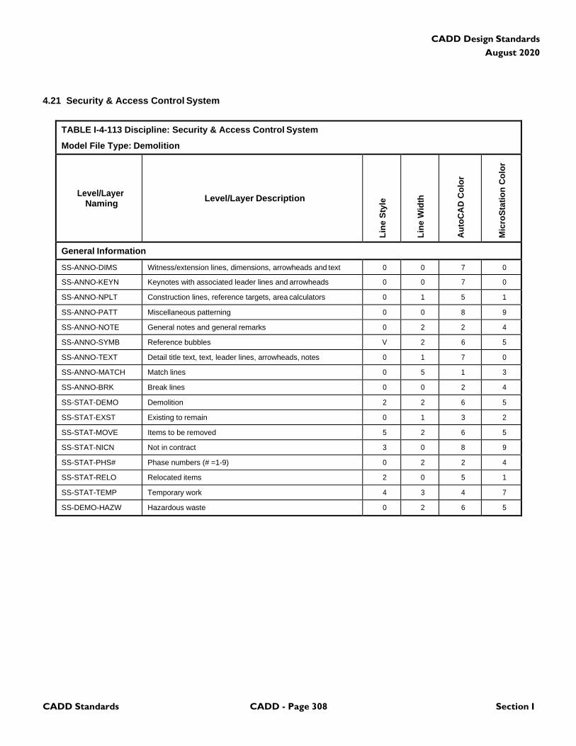
CADD Standards CADD - Page 308 Section I
CADD Design Standards
August 2020
4.21 Security & Access Control System
TABLE I-4-113 Discipline: Security & Access Control System
Model File Type: Demolition
Level/Layer
Naming
Level/Layer Description
Lin
e S
tyle
Lin
e W
idth
Au
toC
AD
Co
lor
Mic
roS
tati
on
Co
lor
General Information
SS-ANNO-DIMS Witness/extension lines, dimensions, arrowheads and text 0 0 7 0
SS-ANNO-KEYN Keynotes with associated leader lines and arrowheads 0 0 7 0
SS-ANNO-NPLT Construction lines, reference targets, area calculators 0 1 5 1
SS-ANNO-PATT Miscellaneous patterning 0 0 8 9
SS-ANNO-NOTE General notes and general remarks 0 2 2 4
SS-ANNO-SYMB Reference bubbles V 2 6 5
SS-ANNO-TEXT Detail title text, text, leader lines, arrowheads, notes 0 1 7 0
SS-ANNO-MATCH Match lines 0 5 1 3
SS-ANNO-BRK Break lines 0 0 2 4
SS-STAT-DEMO Demolition 2 2 6 5
SS-STAT-EXST Existing to remain 0 1 3 2
SS-STAT-MOVE Items to be removed 5 2 6 5
SS-STAT-NICN Not in contract 3 0 8 9
SS-STAT-PHS# Phase numbers (# =1-9) 0 2 2 4
SS-STAT-RELO Relocated items 2 0 5 1
SS-STAT-TEMP Temporary work 4 3 4 7
SS-DEMO-HAZW Hazardous waste 0 2 6 5
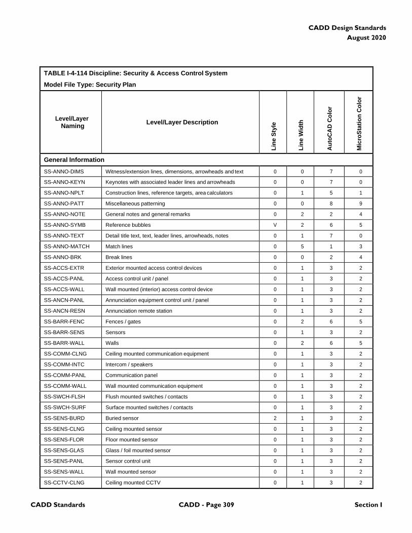
CADD Standards CADD - Page 309 Section I
CADD Design Standards
August 2020
TABLE I-4-114 Discipline: Security & Access Control System
Model File Type: Security Plan
Level/Layer
Naming
Level/Layer Description
Lin
e S
tyle
Lin
e W
idth
Au
toC
AD
Co
lor
Mic
roS
tati
on
Co
lor
General Information
SS-ANNO-DIMS Witness/extension lines, dimensions, arrowheads and text 0 0 7 0
SS-ANNO-KEYN Keynotes with associated leader lines and arrowheads 0 0 7 0
SS-ANNO-NPLT Construction lines, reference targets, area calculators 0 1 5 1
SS-ANNO-PATT Miscellaneous patterning 0 0 8 9
SS-ANNO-NOTE General notes and general remarks 0 2 2 4
SS-ANNO-SYMB Reference bubbles V 2 6 5
SS-ANNO-TEXT Detail title text, text, leader lines, arrowheads, notes 0 1 7 0
SS-ANNO-MATCH Match lines 0 5 1 3
SS-ANNO-BRK Break lines 0 0 2 4
SS-ACCS-EXTR Exterior mounted access control devices 0 1 3 2
SS-ACCS-PANL Access control unit / panel 0 1 3 2
SS-ACCS-WALL Wall mounted (interior) access control device 0 1 3 2
SS-ANCN-PANL Annunciation equipment control unit / panel 0 1 3 2
SS-ANCN-RESN Annunciation remote station 0 1 3 2
SS-BARR-FENC Fences / gates 0 2 6 5
SS-BARR-SENS Sensors 0 1 3 2
SS-BARR-WALL Walls 0 2 6 5
SS-COMM-CLNG Ceiling mounted communication equipment 0 1 3 2
SS-COMM-INTC Intercom / speakers 0 1 3 2
SS-COMM-PANL Communication panel 0 1 3 2
SS-COMM-WALL Wall mounted communication equipment 0 1 3 2
SS-SWCH-FLSH Flush mounted switches / contacts 0 1 3 2
SS-SWCH-SURF Surface mounted switches / contacts 0 1 3 2
SS-SENS-BURD Buried sensor 2 1 3 2
SS-SENS-CLNG Ceiling mounted sensor 0 1 3 2
SS-SENS-FLOR Floor mounted sensor 0 1 3 2
SS-SENS-GLAS Glass / foil mounted sensor 0 1 3 2
SS-SENS-PANL Sensor control unit 0 1 3 2
SS-SENS-WALL Wall mounted sensor 0 1 3 2
SS-CCTV-CLNG Ceiling mounted CCTV 0 1 3 2
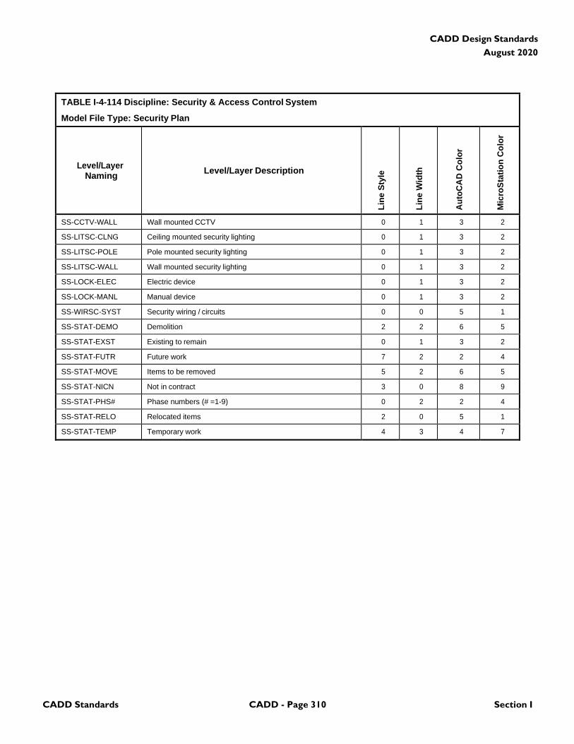
CADD Standards CADD - Page 310 Section I
CADD Design Standards
August 2020
TABLE I-4-114 Discipline: Security & Access Control System
Model File Type: Security Plan
Level/Layer
Naming
Level/Layer Description
Lin
e S
tyle
Lin
e W
idth
Au
toC
AD
Co
lor
Mic
roS
tati
on
Co
lor
SS-CCTV-WALL Wall mounted CCTV 0 1 3 2
SS-LITSC-CLNG Ceiling mounted security lighting 0 1 3 2
SS-LITSC-POLE Pole mounted security lighting 0 1 3 2
SS-LITSC-WALL Wall mounted security lighting 0 1 3 2
SS-LOCK-ELEC Electric device 0 1 3 2
SS-LOCK-MANL Manual device 0 1 3 2
SS-WIRSC-SYST Security wiring / circuits 0 0 5 1
SS-STAT-DEMO Demolition 2 2 6 5
SS-STAT-EXST Existing to remain 0 1 3 2
SS-STAT-FUTR Future work 7 2 2 4
SS-STAT-MOVE Items to be removed 5 2 6 5
SS-STAT-NICN Not in contract 3 0 8 9
SS-STAT-PHS# Phase numbers (# =1-9) 0 2 2 4
SS-STAT-RELO Relocated items 2 0 5 1
SS-STAT-TEMP Temporary work 4 3 4 7

CADD Standards CADD - Page 311 Section I
CADD Design Standards
August 2020
TABLE I-4-115 Discipline: Security & Access Control System
Model File Type: Riser Diagrams
Level/Layer
Naming
Level/Layer Description
Lin
e S
tyle
Lin
e W
idth
Au
toC
AD
Co
lor
Mic
roS
tati
on
Co
lor
General Information
SS-ANNO-DIMS Witness/extension lines, dimensions, arrowheads and text 0 0 7 0
SS-ANNO-KEYN Keynotes with associated leader lines and arrowheads 0 0 7 0
SS-ANNO-NPLT Construction lines, reference targets, area calculators 0 1 5 1
SS-ANNO-PATT Miscellaneous patterning 0 0 8 9
SS-ANNO-NOTE General notes and general remarks 0 2 2 4
SS-ANNO-SYMB Reference bubbles V 2 6 5
SS-ANNO-TEXT Detail title text, text, leader lines, arrowheads, notes 0 1 7 0
SS-ANNO-MATCH Match lines 0 5 1 3
SS-ANNO-BRK Break lines 0 0 2 4
SS-CNTL-ANTA Antenna V 1 3 2
SS-CNTL-AVLV Arrestor valves V 1 3 2
SS-CNTL-BATR Batteries V 1 3 2
SS-CNTL-CAPT Capacitor V 1 3 2
SS-CNTL-CKTB Circuit boards V 1 3 2
SS-CNTL-CONT Contacts V 1 3 2
SS-CNTL-FUSE Fuses V 1 3 2
SS-CNTL-GENR Generators V 1 3 2
SS-CNTL-GRND Grounds V 1 3 2
SS-CNTL-METR Metering devices V 1 3 2
SS-CNTL-MOTR Motors V 1 3 2
SS-CNTL-OVLD Overloads V 1 3 2
SS-CNTL-RACT Reactors V 1 3 2
SS-CNTL-RELA Relays V 1 3 2
SS-CNTL-RSTR Resistors V 1 3 2
SS-CNTL-SWCH Switches V 1 3 2
SS-CNTL-XFMR Transformers V 1 3 2
SS-ALRM-DUCT Smoke detectors, heat sensors 0 1 3 2
SS-LINSC-LW18 Extra fine line work V 0 5 1
SS-LINSC-LW25 Fine line work V 1 1 3
SS-LINSC-LW35 Medium line work V 2 2 4
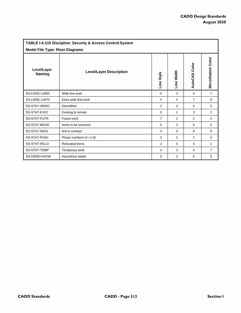
CADD Standards CADD - Page 312 Section I
CADD Design Standards
August 2020
TABLE I-4-115 Discipline: Security & Access Control System
Model File Type: Riser Diagrams
Level/Layer
Naming
Level/Layer Description
Lin
e S
tyle
Lin
e W
idth
Au
toC
AD
Co
lor
Mic
roS
tati
on
Co
lor
SS-LINSC-LW50 Wide line work V 3 4 7
SS-LINSC-LW70 Extra wide line work V 4 7 0
SS-STAT-DEMO Demolition 2 2 6 5
SS-STAT-EXST Existing to remain 0 1 3 2
SS-STAT-FUTR Future work 7 2 2 4
SS-STAT-MOVE Items to be removed 5 2 6 5
SS-STAT-NICN Not in contract 3 0 8 9
SS-STAT-PHS# Phase numbers (# =1-9) 0 2 2 4
SS-STAT-RELO Relocated items 2 0 5 1
SS-STAT-TEMP Temporary work 4 3 4 7
SS-DEMO-HAZW Hazardous waste 0 2 6 5
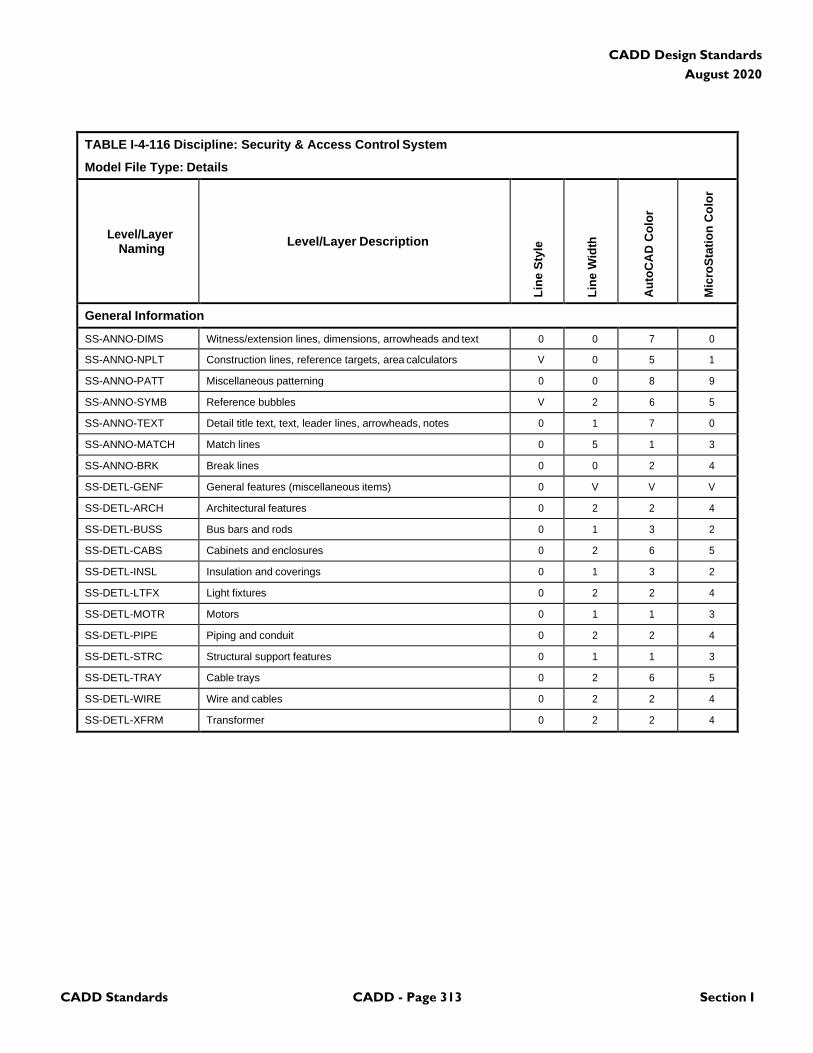
CADD Standards CADD - Page 313 Section I
CADD Design Standards
August 2020
TABLE I-4-116 Discipline: Security & Access Control System
Model File Type: Details
Level/Layer
Naming
Level/Layer Description
Lin
e S
tyle
Lin
e W
idth
Au
toC
AD
Co
lor
Mic
roS
tati
on
Co
lor
General Information
SS-ANNO-DIMS Witness/extension lines, dimensions, arrowheads and text 0 0 7 0
SS-ANNO-NPLT Construction lines, reference targets, area calculators V 0 5 1
SS-ANNO-PATT Miscellaneous patterning 0 0 8 9
SS-ANNO-SYMB Reference bubbles V 2 6 5
SS-ANNO-TEXT Detail title text, text, leader lines, arrowheads, notes 0 1 7 0
SS-ANNO-MATCH Match lines 0 5 1 3
SS-ANNO-BRK Break lines 0 0 2 4
SS-DETL-GENF General features (miscellaneous items) 0 V V V
SS-DETL-ARCH Architectural features 0 2 2 4
SS-DETL-BUSS Bus bars and rods 0 1 3 2
SS-DETL-CABS Cabinets and enclosures 0 2 6 5
SS-DETL-INSL Insulation and coverings 0 1 3 2
SS-DETL-LTFX Light fixtures 0 2 2 4
SS-DETL-MOTR Motors 0 1 1 3
SS-DETL-PIPE Piping and conduit 0 2 2 4
SS-DETL-STRC Structural support features 0 1 1 3
SS-DETL-TRAY Cable trays 0 2 6 5
SS-DETL-WIRE Wire and cables 0 2 2 4
SS-DETL-XFRM Transformer 0 2 2 4

CADD Standards CADD - Page 314 Section I
CADD Design Standards
August 2020
4.22 Public Information System
TABLE I-4-117 Discipline: Public Information System
Model File Type: Demolition Plan
Level/Layer
Naming
Level/Layer Description
Lin
e S
tyle
Lin
e W
idth
Au
toC
AD
Co
lor
Mic
roS
tati
on
Co
lor
General Information
PS-ANNO-DIMS Witness extension lines, dimensions arrowheads and text 0 V V V
PS-ANNO-KEYN Keynote with associated leaderlines and arrowheads 0 V V V
PS-ANNO-NPLT Construction lines, reference targets, area calculations V 0 5 1
PS-ANNO-PATT Miscellaneous patterning 0 0 8 9
PS-ANNO-NOTE General note and general remarks 0 2 2 4
PS-ANNO-SYMB Reference bubbles, matchlines, breaklines V 2 6 5
PS-ANNO-TEXT Detail title text, leaderlines, arrowheads, notes 0 V V V
PS-STAT-DEMO Demolition 2 2 6 5
PS-STAT-EXST Existing to remain 0 1 3 2
PS-STAT-MOVE Items to be moved 5 2 6 5
PS-STAT-NICN Not in contract 3 0 8 9
PS-STAT-PHS# Phase numbers (# = 1-9) 0 2 2 4
PS-STAT-RELO Relocated items 2 0 5 1
PS-STAT-TEMP Temporary work 4 3 4 7
PS-DEMO-HAZW Hazardous waste 0 2 6 5
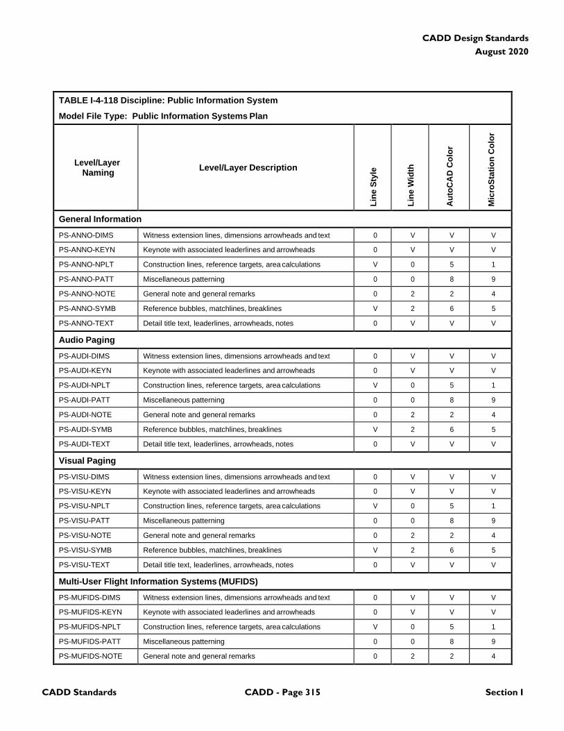
CADD Standards CADD - Page 315 Section I
CADD Design Standards
August 2020
TABLE I-4-118 Discipline: Public Information System
Model File Type: Public Information Systems Plan
Level/Layer
Naming
Level/Layer Description
Lin
e S
tyle
Lin
e W
idth
Au
toC
AD
Co
lor
Mic
roS
tati
on
Co
lor
General Information
PS-ANNO-DIMS Witness extension lines, dimensions arrowheads and text 0 V V V
PS-ANNO-KEYN Keynote with associated leaderlines and arrowheads 0 V V V
PS-ANNO-NPLT Construction lines, reference targets, area calculations V 0 5 1
PS-ANNO-PATT Miscellaneous patterning 0 0 8 9
PS-ANNO-NOTE General note and general remarks 0 2 2 4
PS-ANNO-SYMB Reference bubbles, matchlines, breaklines V 2 6 5
PS-ANNO-TEXT Detail title text, leaderlines, arrowheads, notes 0 V V V
Audio Paging
PS-AUDI-DIMS Witness extension lines, dimensions arrowheads and text 0 V V V
PS-AUDI-KEYN Keynote with associated leaderlines and arrowheads 0 V V V
PS-AUDI-NPLT Construction lines, reference targets, area calculations V 0 5 1
PS-AUDI-PATT Miscellaneous patterning 0 0 8 9
PS-AUDI-NOTE General note and general remarks 0 2 2 4
PS-AUDI-SYMB Reference bubbles, matchlines, breaklines V 2 6 5
PS-AUDI-TEXT Detail title text, leaderlines, arrowheads, notes 0 V V V
Visual Paging
PS-VISU-DIMS Witness extension lines, dimensions arrowheads and text 0 V V V
PS-VISU-KEYN Keynote with associated leaderlines and arrowheads 0 V V V
PS-VISU-NPLT Construction lines, reference targets, area calculations V 0 5 1
PS-VISU-PATT Miscellaneous patterning 0 0 8 9
PS-VISU-NOTE General note and general remarks 0 2 2 4
PS-VISU-SYMB Reference bubbles, matchlines, breaklines V 2 6 5
PS-VISU-TEXT Detail title text, leaderlines, arrowheads, notes 0 V V V
Multi-User Flight Information Systems (MUFIDS)
PS-MUFIDS-DIMS Witness extension lines, dimensions arrowheads and text 0 V V V
PS-MUFIDS-KEYN Keynote with associated leaderlines and arrowheads 0 V V V
PS-MUFIDS-NPLT Construction lines, reference targets, area calculations V 0 5 1
PS-MUFIDS-PATT Miscellaneous patterning 0 0 8 9
PS-MUFIDS-NOTE General note and general remarks 0 2 2 4
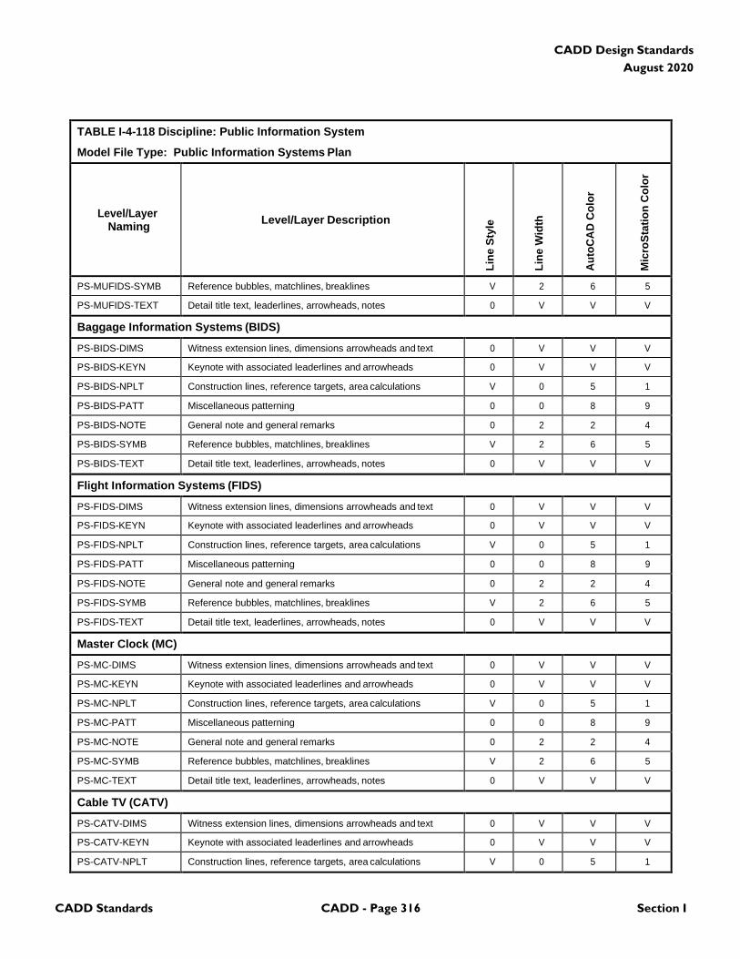
CADD Standards CADD - Page 316 Section I
CADD Design Standards
August 2020
TABLE I-4-118 Discipline: Public Information System
Model File Type: Public Information Systems Plan
Level/Layer
Naming
Level/Layer Description
Lin
e S
tyle
Lin
e W
idth
Au
toC
AD
Co
lor
Mic
roS
tati
on
Co
lor
PS-MUFIDS-SYMB Reference bubbles, matchlines, breaklines V 2 6 5
PS-MUFIDS-TEXT Detail title text, leaderlines, arrowheads, notes 0 V V V
Baggage Information Systems (BIDS)
PS-BIDS-DIMS Witness extension lines, dimensions arrowheads and text 0 V V V
PS-BIDS-KEYN Keynote with associated leaderlines and arrowheads 0 V V V
PS-BIDS-NPLT Construction lines, reference targets, area calculations V 0 5 1
PS-BIDS-PATT Miscellaneous patterning 0 0 8 9
PS-BIDS-NOTE General note and general remarks 0 2 2 4
PS-BIDS-SYMB Reference bubbles, matchlines, breaklines V 2 6 5
PS-BIDS-TEXT Detail title text, leaderlines, arrowheads, notes 0 V V V
Flight Information Systems (FIDS)
PS-FIDS-DIMS Witness extension lines, dimensions arrowheads and text 0 V V V
PS-FIDS-KEYN Keynote with associated leaderlines and arrowheads 0 V V V
PS-FIDS-NPLT Construction lines, reference targets, area calculations V 0 5 1
PS-FIDS-PATT Miscellaneous patterning 0 0 8 9
PS-FIDS-NOTE General note and general remarks 0 2 2 4
PS-FIDS-SYMB Reference bubbles, matchlines, breaklines V 2 6 5
PS-FIDS-TEXT Detail title text, leaderlines, arrowheads, notes 0 V V V
Master Clock (MC)
PS-MC-DIMS Witness extension lines, dimensions arrowheads and text 0 V V V
PS-MC-KEYN Keynote with associated leaderlines and arrowheads 0 V V V
PS-MC-NPLT Construction lines, reference targets, area calculations V 0 5 1
PS-MC-PATT Miscellaneous patterning 0 0 8 9
PS-MC-NOTE General note and general remarks 0 2 2 4
PS-MC-SYMB Reference bubbles, matchlines, breaklines V 2 6 5
PS-MC-TEXT Detail title text, leaderlines, arrowheads, notes 0 V V V
Cable TV (CATV)
PS-CATV-DIMS Witness extension lines, dimensions arrowheads and text 0 V V V
PS-CATV-KEYN Keynote with associated leaderlines and arrowheads 0 V V V
PS-CATV-NPLT Construction lines, reference targets, area calculations V 0 5 1
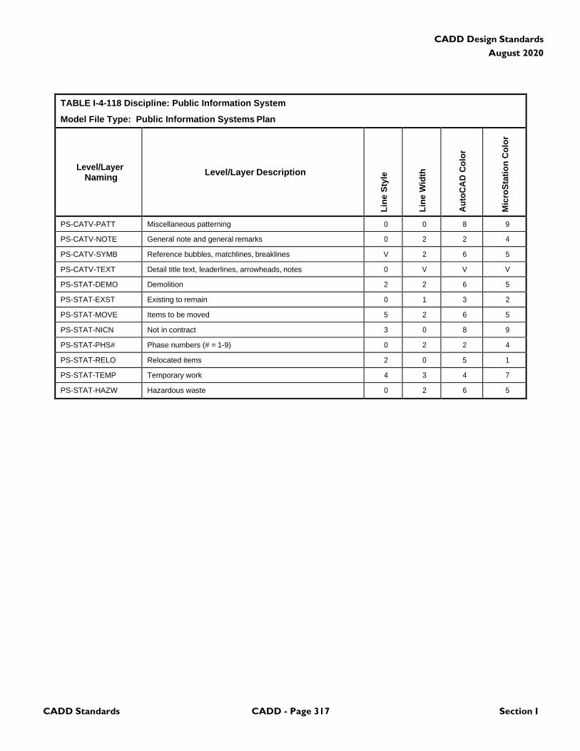
CADD Standards CADD - Page 317 Section I
CADD Design Standards
August 2020
TABLE I-4-118 Discipline: Public Information System
Model File Type: Public Information Systems Plan
Level/Layer
Naming
Level/Layer Description
Lin
e S
tyle
Lin
e W
idth
Au
toC
AD
Co
lor
Mic
roS
tati
on
Co
lor
PS-CATV-PATT Miscellaneous patterning 0 0 8 9
PS-CATV-NOTE General note and general remarks 0 2 2 4
PS-CATV-SYMB Reference bubbles, matchlines, breaklines V 2 6 5
PS-CATV-TEXT Detail title text, leaderlines, arrowheads, notes 0 V V V
PS-STAT-DEMO Demolition 2 2 6 5
PS-STAT-EXST Existing to remain 0 1 3 2
PS-STAT-MOVE Items to be moved 5 2 6 5
PS-STAT-NICN Not in contract 3 0 8 9
PS-STAT-PHS# Phase numbers (# = 1-9) 0 2 2 4
PS-STAT-RELO Relocated items 2 0 5 1
PS-STAT-TEMP Temporary work 4 3 4 7
PS-STAT-HAZW Hazardous waste 0 2 6 5
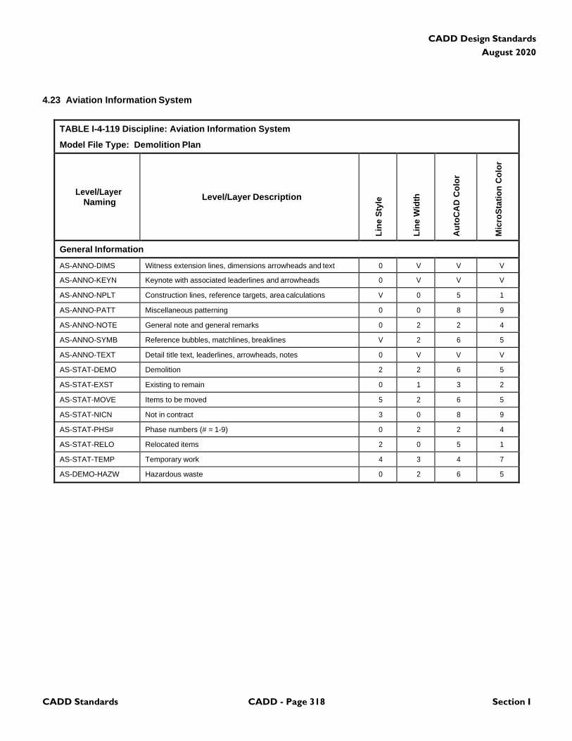
CADD Standards CADD - Page 318 Section I
CADD Design Standards
August 2020
4.23 Aviation Information System
TABLE I-4-119 Discipline: Aviation Information System
Model File Type: Demolition Plan
Level/Layer
Naming
Level/Layer Description
Lin
e S
tyle
Lin
e W
idth
Au
toC
AD
Co
lor
Mic
roS
tati
on
Co
lor
General Information
AS-ANNO-DIMS Witness extension lines, dimensions arrowheads and text 0 V V V
AS-ANNO-KEYN Keynote with associated leaderlines and arrowheads 0 V V V
AS-ANNO-NPLT Construction lines, reference targets, area calculations V 0 5 1
AS-ANNO-PATT Miscellaneous patterning 0 0 8 9
AS-ANNO-NOTE General note and general remarks 0 2 2 4
AS-ANNO-SYMB Reference bubbles, matchlines, breaklines V 2 6 5
AS-ANNO-TEXT Detail title text, leaderlines, arrowheads, notes 0 V V V
AS-STAT-DEMO Demolition 2 2 6 5
AS-STAT-EXST Existing to remain 0 1 3 2
AS-STAT-MOVE Items to be moved 5 2 6 5
AS-STAT-NICN Not in contract 3 0 8 9
AS-STAT-PHS# Phase numbers (# = 1-9) 0 2 2 4
AS-STAT-RELO Relocated items 2 0 5 1
AS-STAT-TEMP Temporary work 4 3 4 7
AS-DEMO-HAZW Hazardous waste 0 2 6 5
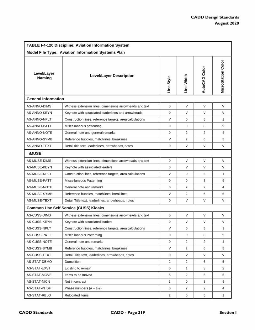
CADD Standards CADD - Page 319 Section I
CADD Design Standards
August 2020
TABLE I-4-120 Discipline: Aviation Information System
Model File Type: Aviation Information Systems Plan
Level/Layer
Naming
Level/Layer Description
Lin
e S
tyle
Lin
e W
idth
Au
toC
AD
Co
lor
Mic
roS
tati
on
Co
lor
General Information
AS-ANNO-DIMS Witness extension lines, dimensions arrowheads and text 0 V V V
AS-ANNO-KEYN Keynote with associated leaderlines and arrowheads 0 V V V
AS-ANNO-NPLT Construction lines, reference targets, area calculations V 0 5 1
AS-ANNO-PATT Miscellaneous patterning 0 0 8 9
AS-ANNO-NOTE General note and general remarks 0 2 2 4
AS-ANNO-SYMB Reference bubbles, matchlines, breaklines V 2 6 5
AS-ANNO-TEXT Detail title text, leaderlines, arrowheads, notes 0 V V V
iMUSE
AS-MUSE-DIMS Witness extension lines, dimensions arrowheads and text 0 V V V
AS-MUSE-KEYN Keynote with associated leaders 0 V V V
AS-MUSE-NPLT Construction lines, reference targets, area calculations V 0 5 1
AS-MUSE-PATT Miscellaneous Patterning 0 0 8 9
AS-MUSE-NOTE General note and remarks 0 2 2 4
AS-MUSE-SYMB Reference bubbles, matchlines, breaklines V 2 6 5
AS-MUSE-TEXT Detail Title text, leaderlines, arrowheads, notes 0 V V V
Common Use Self Service (CUSS) Kiosks
AS-CUSS-DIMS Witness extension lines, dimensions arrowheads and text 0 V V V
AS-CUSS-KEYN Keynote with associated leaders 0 V V V
AS-CUSS-NPLT Construction lines, reference targets, area calculations V 0 5 1
AS-CUSS-PATT Miscellaneous Patterning 0 0 8 9
AS-CUSS-NOTE General note and remarks 0 2 2 4
AS-CUSS-SYMB Reference bubbles, matchlines, breaklines V 2 6 5
AS-CUSS-TEXT Detail Title text, leaderlines, arrowheads, notes 0 V V V
AS-STAT-DEMO Demolition 2 2 6 5
AS-STAT-EXST Existing to remain 0 1 3 2
AS-STAT-MOVE Items to be moved 5 2 6 5
AS-STAT-NICN Not in contract 3 0 8 9
AS-STAT-PHS# Phase numbers (# = 1-9) 0 2 2 4
AS-STAT-RELO Relocated items 2 0 5 1
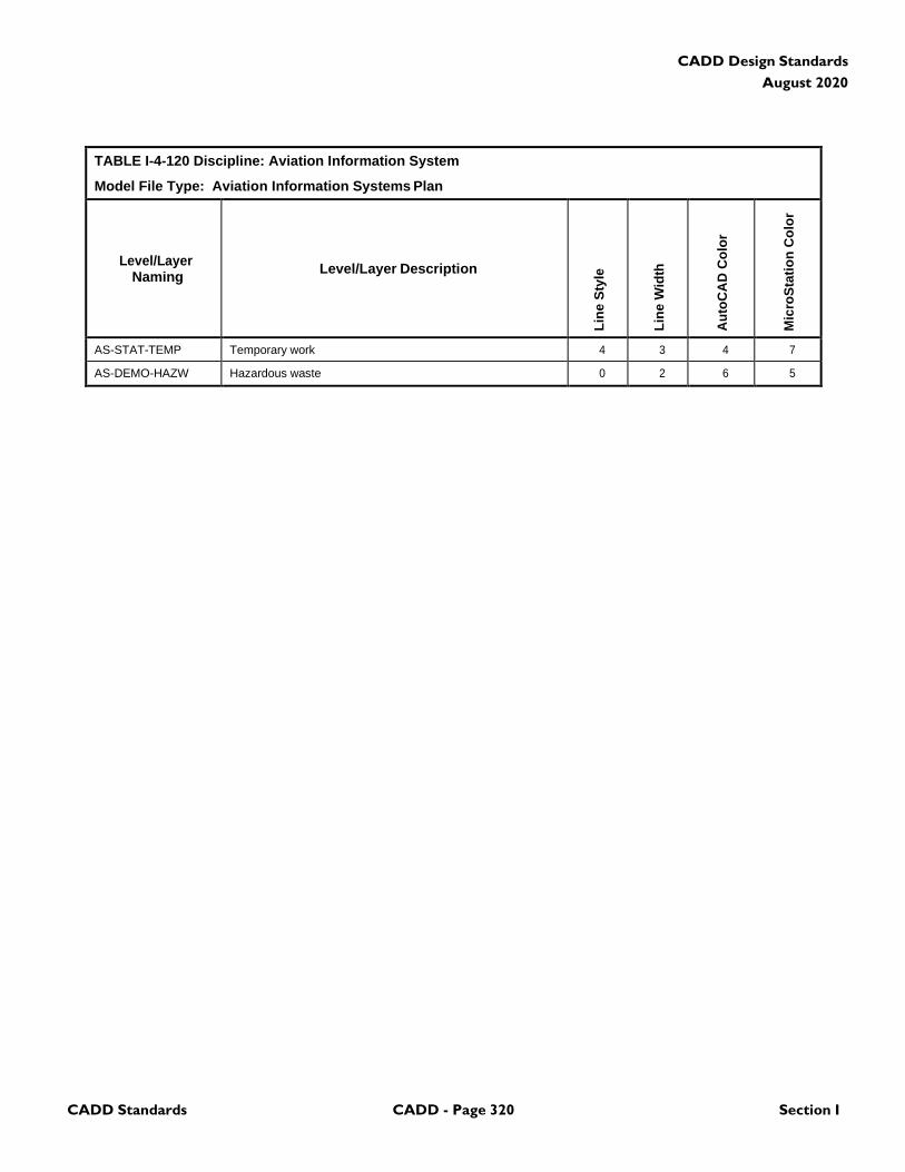
CADD Standards CADD - Page 320 Section I
CADD Design Standards
August 2020
TABLE I-4-120 Discipline: Aviation Information System
Model File Type: Aviation Information Systems Plan
Level/Layer
Naming
Level/Layer Description
Lin
e S
tyle
Lin
e W
idth
Au
toC
AD
Co
lor
Mic
roS
tati
on
Co
lor
AS-STAT-TEMP Temporary work 4 3 4 7
AS-DEMO-HAZW Hazardous waste 0 2 6 5

CADD Standards CADD - Page 321 Section I
CADD Design Standards
August 2020
4.24 Electronic Monitoring System
TABLE I-4-121 Discipline: Electronic Monitoring System
Model File Type: Demolition Plan
Level/Layer
Naming
Level/Layer Description
Lin
e S
tyle
Lin
e W
idth
Au
toC
AD
Co
lor
Mic
roS
tati
on
Co
lor
General Information
ES-ANNO-DIMS Witness extension lines, dimensions arrowheads and text 0 V V V
ES-ANNO-KEYN Keynote with associated leaderlines and arrowheads 0 V V V
ES-ANNO-NPLT Construction lines, reference targets, area calculations V 0 5 1
ES-ANNO-PATT Miscellaneous patterning 0 0 8 9
ES-ANNO-NOTE General note and general remarks 0 2 2 4
ES-ANNO-SYMB Reference bubbles, matchlines, breaklines V 2 6 5
ES-ANNO-TEXT Detail title text, leaderlines, arrowheads, notes 0 V V V
ES-STAT-DEMO Demolition 2 2 6 5
ES-STAT-EXST Existing to remain 0 1 3 2
ES-STAT-MOVE Items to be moved 5 2 6 5
ES-STAT-NICN Not in contract 3 0 8 9
ES-STAT-PHS# Phase numbers (# = 1-9) 0 2 2 4
ES-STAT-RELO Relocated items 2 0 5 1
ES-STAT-TEMP Temporary work 4 3 4 7
ES-DEMO-HAZW Hazardous waste 0 2 6 5
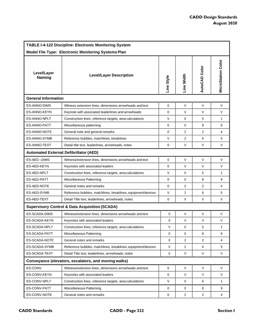
CADD Standards CADD - Page 322 Section I
CADD Design Standards
August 2020
TABLE I-4-122 Discipline: Electronic Monitoring System
Model File Type: Electronic Monitoring Systems Plan
Level/Layer
Naming
Level/Layer Description
Lin
e S
tyle
Lin
e W
idth
Au
toC
AD
Co
lor
Mic
roS
tati
on
Co
lor
General Information
ES-ANNO-DIMS Witness extension lines, dimensions arrowheads and text 0 V V V
ES-ANNO-KEYN Keynote with associated leaderlines and arrowheads 0 V V V
ES-ANNO-NPLT Construction lines, reference targets, area calculations V 0 5 1
ES-ANNO-PATT Miscellaneous patterning 0 0 8 9
ES-ANNO-NOTE General note and general remarks 0 2 2 4
ES-ANNO-SYMB Reference bubbles, matchlines, breaklines V 2 6 5
ES-ANNO-TEXT Detail title text, leaderlines, arrowheads, notes 0 V V V
Automated External Defibrillator (AED)
ES-AED –DIMS Witness/extension lines, dimensions arrowheads and text 0 V V V
ES-AED-KEYN Keynotes with associated leaders 0 V V V
ES-AED-NPLT Construction lines, reference targets, area calculations V 0 5 1
ES-AED-PATT Miscellaneous Patterning 0 0 8 9
ES-AED-NOTE General notes and remarks 0 2 2 4
ES-AED-SYMB Reference bubbles, matchlines, breaklines, equipment/devices V 2 6 5
ES-AED-TEXT Detail Title text, leaderlines, arrowheads, notes 0 V V V
Supervisory Control & Data Acquisition (SCADA)
ES-SCADA-DIMS Witness/extension lines, dimensions arrowheads and text 0 V V V
ES-SCADA-KEYN Keynotes with associated leaders 0 V V V
ES-SCADA-NPLT Construction lines, reference targets, area calculations V 0 5 1
ES-SCADA-PATT Miscellaneous Patterning 0 0 8 9
ES-SCADA-NOTE General notes and remarks 0 2 2 4
ES-SCADA-SYMB Reference bubbles, matchlines, breaklines, equipment/devices V 2 6 5
ES-SCADA-TEXT Detail Title text, leaderlines, arrowheads, notes 0 V V V
Conveyance (elevators, escalators, and moving walks)
ES-CONV Witness/extension lines, dimensions arrowheads and text 0 V V V
ES-CONV-KEYN Keynotes with associated leaders 0 V V V
ES-CONV-NPLT Construction lines, reference targets, area calculations V 0 5 1
ES-CONV-PATT Miscellaneous Patterning 0 0 8 9
ES-CONV-NOTE General notes and remarks 0 2 2 4
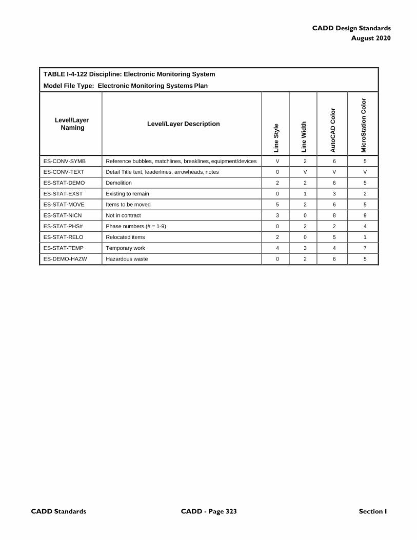
CADD Standards CADD - Page 323 Section I
CADD Design Standards
August 2020
TABLE I-4-122 Discipline: Electronic Monitoring System
Model File Type: Electronic Monitoring Systems Plan
Level/Layer
Naming
Level/Layer Description
Lin
e S
tyle
Lin
e W
idth
Au
toC
AD
Co
lor
Mic
roS
tati
on
Co
lor
ES-CONV-SYMB Reference bubbles, matchlines, breaklines, equipment/devices V 2 6 5
ES-CONV-TEXT Detail Title text, leaderlines, arrowheads, notes 0 V V V
ES-STAT-DEMO Demolition 2 2 6 5
ES-STAT-EXST Existing to remain 0 1 3 2
ES-STAT-MOVE Items to be moved 5 2 6 5
ES-STAT-NICN Not in contract 3 0 8 9
ES-STAT-PHS# Phase numbers (# = 1-9) 0 2 2 4
ES-STAT-RELO Relocated items 2 0 5 1
ES-STAT-TEMP Temporary work 4 3 4 7
ES-DEMO-HAZW Hazardous waste 0 2 6 5

CADD Standards CADD - Page 324 Section I
CADD Design Standards
August 2020
(This Page Blank)
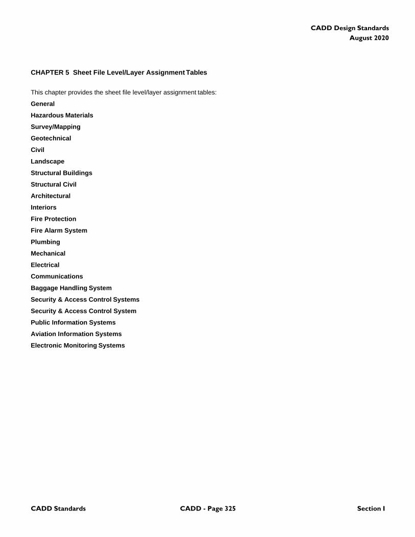
CADD Standards CADD - Page 325 Section I
CADD Design Standards
August 2020
CHAPTER 5 Sheet File Level/Layer Assignment Tables
This chapter provides the sheet file level/layer assignment tables:
General
Hazardous Materials
Survey/Mapping
Geotechnical
Civil
Landscape
Structural Buildings
Structural Civil
Architectural
Interiors
Fire Protection
Fire Alarm System
Plumbing
Mechanical
Electrical
Communications
Baggage Handling System
Security & Access Control Systems
Security & Access Control System
Public Information Systems
Aviation Information Systems
Electronic Monitoring Systems
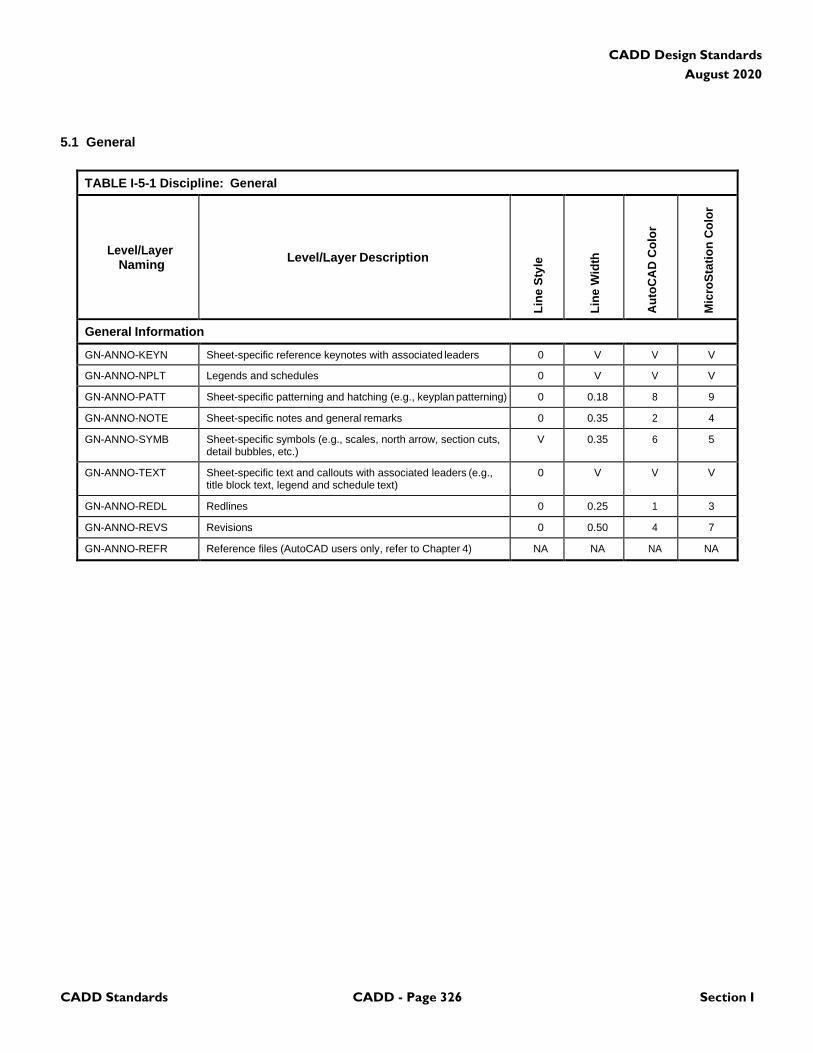
CADD Standards CADD - Page 326 Section I
CADD Design Standards
August 2020
5.1 General
TABLE I-5-1 Discipline: General
Level/Layer
Naming
Level/Layer Description
Lin
e S
tyle
Lin
e W
idth
Au
toC
AD
Co
lor
Mic
roS
tati
on
Co
lor
General Information
GN-ANNO-KEYN Sheet-specific reference keynotes with associated leaders 0 V V V
GN-ANNO-NPLT Legends and schedules 0 V V V
GN-ANNO-PATT Sheet-specific patterning and hatching (e.g., keyplan patterning) 0 0.18 8 9
GN-ANNO-NOTE Sheet-specific notes and general remarks 0 0.35 2 4
GN-ANNO-SYMB Sheet-specific symbols (e.g., scales, north arrow, section cuts, detail bubbles, etc.)
V 0.35 6 5
GN-ANNO-TEXT Sheet-specific text and callouts with associated leaders (e.g., title block text, legend and schedule text)
0 V V V
GN-ANNO-REDL Redlines 0 0.25 1 3
GN-ANNO-REVS Revisions 0 0.50 4 7
GN-ANNO-REFR Reference files (AutoCAD users only, refer to Chapter 4) NA NA NA NA
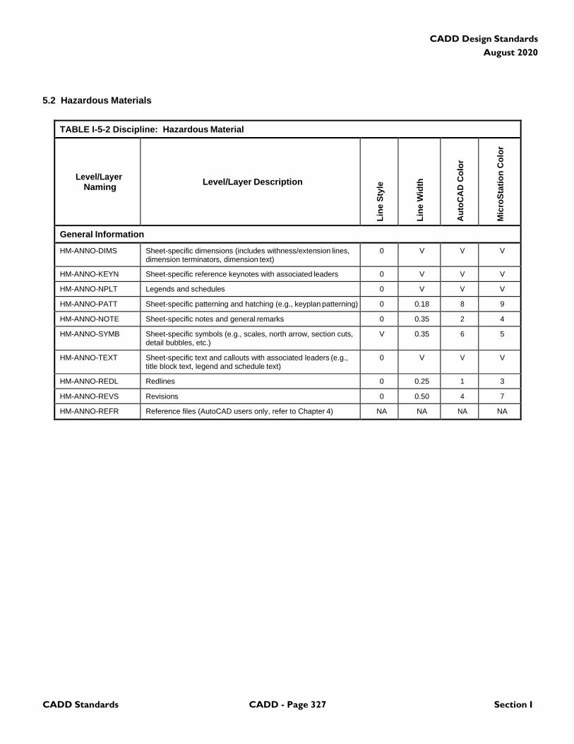
CADD Standards CADD - Page 327 Section I
CADD Design Standards
August 2020
5.2 Hazardous Materials
TABLE I-5-2 Discipline: Hazardous Material
Level/Layer
Naming
Level/Layer Description
Lin
e S
tyle
Lin
e W
idth
Au
toC
AD
Co
lor
Mic
roS
tati
on
Co
lor
General Information
HM-ANNO-DIMS Sheet-specific dimensions (includes withness/extension lines, dimension terminators, dimension text)
0 V V V
HM-ANNO-KEYN Sheet-specific reference keynotes with associated leaders 0 V V V
HM-ANNO-NPLT Legends and schedules 0 V V V
HM-ANNO-PATT Sheet-specific patterning and hatching (e.g., keyplan patterning) 0 0.18 8 9
HM-ANNO-NOTE Sheet-specific notes and general remarks 0 0.35 2 4
HM-ANNO-SYMB Sheet-specific symbols (e.g., scales, north arrow, section cuts, detail bubbles, etc.)
V 0.35 6 5
HM-ANNO-TEXT Sheet-specific text and callouts with associated leaders (e.g., title block text, legend and schedule text)
0 V V V
HM-ANNO-REDL Redlines 0 0.25 1 3
HM-ANNO-REVS Revisions 0 0.50 4 7
HM-ANNO-REFR Reference files (AutoCAD users only, refer to Chapter 4) NA NA NA NA
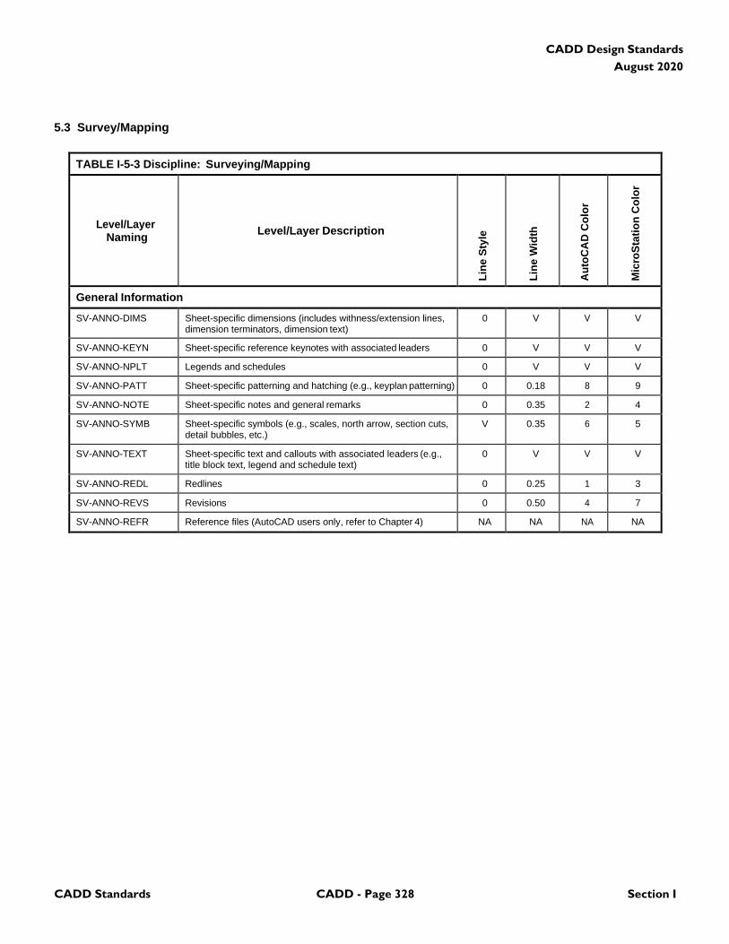
CADD Standards CADD - Page 328 Section I
CADD Design Standards
August 2020
5.3 Survey/Mapping
TABLE I-5-3 Discipline: Surveying/Mapping
Level/Layer
Naming
Level/Layer Description
Lin
e S
tyle
Lin
e W
idth
Au
toC
AD
Co
lor
Mic
roS
tati
on
Co
lor
General Information
SV-ANNO-DIMS Sheet-specific dimensions (includes withness/extension lines, dimension terminators, dimension text)
0 V V V
SV-ANNO-KEYN Sheet-specific reference keynotes with associated leaders 0 V V V
SV-ANNO-NPLT Legends and schedules 0 V V V
SV-ANNO-PATT Sheet-specific patterning and hatching (e.g., keyplan patterning) 0 0.18 8 9
SV-ANNO-NOTE Sheet-specific notes and general remarks 0 0.35 2 4
SV-ANNO-SYMB Sheet-specific symbols (e.g., scales, north arrow, section cuts, detail bubbles, etc.)
V 0.35 6 5
SV-ANNO-TEXT Sheet-specific text and callouts with associated leaders (e.g., title block text, legend and schedule text)
0 V V V
SV-ANNO-REDL Redlines 0 0.25 1 3
SV-ANNO-REVS Revisions 0 0.50 4 7
SV-ANNO-REFR Reference files (AutoCAD users only, refer to Chapter 4) NA NA NA NA

CADD Standards CADD - Page 329 Section I
CADD Design Standards
August 2020
5.4 Geotechnical
TABLE I-5-4 Discipline: Geotechnical
Level/Layer
Naming
Level/Layer Description
Lin
e S
tyle
Lin
e W
idth
Au
toC
AD
Co
lor
Mic
roS
tati
on
Co
lor
General Information
GT-ANNO-DIMS Sheet-specific dimensions (includes withness/extension lines, dimension terminators, dimension text)
0 V V V
GT-ANNO-KEYN Sheet-specific reference keynotes with associated leaders 0 V V V
GT-ANNO-NPLT Legends and schedules 0 V V V
GT-ANNO-PATT Sheet-specific patterning and hatching (e.g., keyplan patterning) 0 0.18 8 9
GT-ANNO-NOTE Sheet-specific notes and general remarks 0 0.35 2 4
GT-ANNO-SYMB Sheet-specific symbols (e.g., scales, north arrow, section cuts, detail bubbles, etc.)
V 0.35 6 5
GT-ANNO-TEXT Sheet-specific text and callouts with associated leaders (e.g., title block text, legend and schedule text)
0 V V V
GT-ANNO-REDL Redlines 0 0.25 1 3
GT-ANNO-REVS Revisions 0 0.50 4 7
GT-ANNO-REFR Reference files (AutoCAD users only, refer to Chapter 4) NA NA NA NA
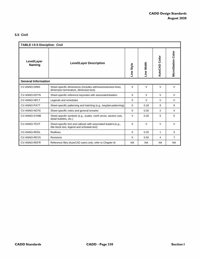
CADD Standards CADD - Page 330 Section I
CADD Design Standards
August 2020
5.5 Civil
TABLE I-5-5 Discipline: Civil
Level/Layer
Naming
Level/Layer Description
Lin
e S
tyle
Lin
e W
idth
Au
toC
AD
Co
lor
Mic
roS
tati
on
Co
lor
General Information
CV-ANNO-DIMS Sheet-specific dimensions (includes withness/extension lines, dimension terminators, dimension text)
0 V V V
CV-ANNO-KEYN Sheet-specific reference keynotes with associated leaders 0 V V V
CV-ANNO-NPLT Legends and schedules 0 V V V
CV-ANNO-PATT Sheet-specific patterning and hatching (e.g., keyplan patterning) 0 0.18 8 9
CV-ANNO-NOTE Sheet-specific notes and general remarks 0 0.35 2 4
CV-ANNO-SYMB Sheet-specific symbols (e.g., scales, north arrow, section cuts, detail bubbles, etc.)
V 0.35 6 5
CV-ANNO-TEXT Sheet-specific text and callouts with associated leaders (e.g., title block text, legend and schedule text)
0 V V V
CV-ANNO-REDL Redlines 0 0.25 1 3
CV-ANNO-REVS Revisions 0 0.50 4 7
CV-ANNO-REFR Reference files (AutoCAD users only, refer to Chapter 4) NA NA NA NA

CADD Standards CADD - Page 331 Section I
CADD Design Standards
August 2020
5.6 Landscape
TABLE I-5-6 Discipline: Landscape
Level/Layer
Naming
Level/Layer Description
Lin
e S
tyle
Lin
e W
idth
Au
toC
AD
Co
lor
Mic
roS
tati
on
Co
lor
General Information
LA-ANNO-DIMS Sheet-specific dimensions (includes withness/extension lines, dimension terminators, dimension text)
0 V V V
LA-ANNO-KEYN Sheet-specific reference keynotes with associated leaders 0 V V V
LA-ANNO-NPLT Legends and schedules 0 V V V
LA-ANNO-PATT Sheet-specific patterning and hatching (e.g., keyplan patterning) 0 0.18 8 9
LA-ANNO-NOTE Sheet-specific notes and general remarks 0 0.35 2 4
LA-ANNO-SYMB Sheet-specific symbols (e.g., scales, north arrow, section cuts, detail bubbles, etc.)
V 0.35 6 5
LA-ANNO-TEXT Sheet-specific text and callouts with associated leaders (e.g., title block text, legend and schedule text)
0 V V V
LA-ANNO-REDL Redlines 0 0.25 1 3
LA-ANNO-REVS Revisions 0 0.50 4 7
LA-ANNO-REFR Reference files (AutoCAD users only, refer to Chapter 4) NA NA NA NA
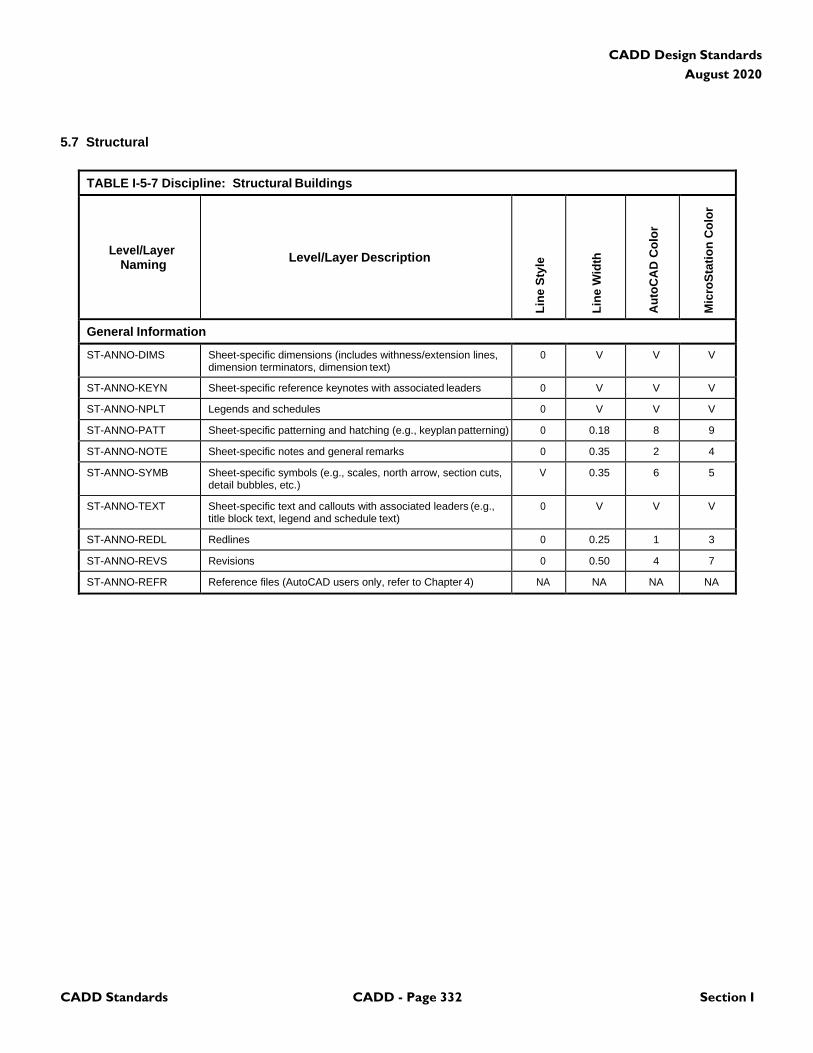
CADD Standards CADD - Page 332 Section I
CADD Design Standards
August 2020
5.7 Structural
TABLE I-5-7 Discipline: Structural Buildings
Level/Layer
Naming
Level/Layer Description
Lin
e S
tyle
Lin
e W
idth
Au
toC
AD
Co
lor
Mic
roS
tati
on
Co
lor
General Information
ST-ANNO-DIMS Sheet-specific dimensions (includes withness/extension lines, dimension terminators, dimension text)
0 V V V
ST-ANNO-KEYN Sheet-specific reference keynotes with associated leaders 0 V V V
ST-ANNO-NPLT Legends and schedules 0 V V V
ST-ANNO-PATT Sheet-specific patterning and hatching (e.g., keyplan patterning) 0 0.18 8 9
ST-ANNO-NOTE Sheet-specific notes and general remarks 0 0.35 2 4
ST-ANNO-SYMB Sheet-specific symbols (e.g., scales, north arrow, section cuts, detail bubbles, etc.)
V 0.35 6 5
ST-ANNO-TEXT Sheet-specific text and callouts with associated leaders (e.g., title block text, legend and schedule text)
0 V V V
ST-ANNO-REDL Redlines 0 0.25 1 3
ST-ANNO-REVS Revisions 0 0.50 4 7
ST-ANNO-REFR Reference files (AutoCAD users only, refer to Chapter 4) NA NA NA NA
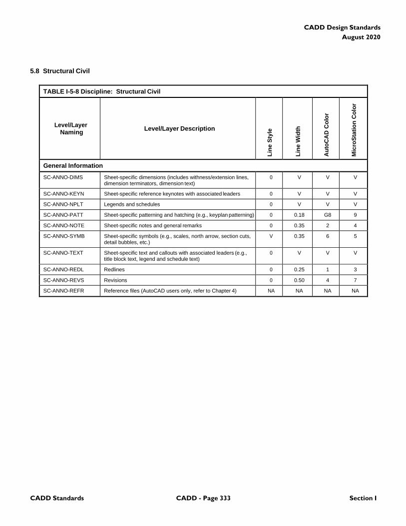
CADD Standards CADD - Page 333 Section I
CADD Design Standards
August 2020
5.8 Structural Civil
TABLE I-5-8 Discipline: Structural Civil
Level/Layer
Naming
Level/Layer Description
Lin
e S
tyle
Lin
e W
idth
Au
toC
AD
Co
lor
Mic
roS
tati
on
Co
lor
General Information
SC-ANNO-DIMS Sheet-specific dimensions (includes withness/extension lines, dimension terminators, dimension text)
0 V V V
SC-ANNO-KEYN Sheet-specific reference keynotes with associated leaders 0 V V V
SC-ANNO-NPLT Legends and schedules 0 V V V
SC-ANNO-PATT Sheet-specific patterning and hatching (e.g., keyplan patterning) 0 0.18 G8 9
SC-ANNO-NOTE Sheet-specific notes and general remarks 0 0.35 2 4
SC-ANNO-SYMB Sheet-specific symbols (e.g., scales, north arrow, section cuts, detail bubbles, etc.)
V 0.35 6 5
SC-ANNO-TEXT Sheet-specific text and callouts with associated leaders (e.g., title block text, legend and schedule text)
0 V V V
SC-ANNO-REDL Redlines 0 0.25 1 3
SC-ANNO-REVS Revisions 0 0.50 4 7
SC-ANNO-REFR Reference files (AutoCAD users only, refer to Chapter 4) NA NA NA NA

CADD Standards CADD - Page 334 Section I
CADD Design Standards
August 2020
5.9 Architectural
TABLE I-5-9 Discipline: Architectural
Level/Layer
Naming
Level/Layer Description
Lin
e S
tyle
Lin
e W
idth
Au
toC
AD
Co
lor
Mic
roS
tati
on
Co
lor
General Information
AR-ANNO-DIMS Sheet-specific dimensions (includes withness/extension lines, dimension terminators, dimension text)
0 V V V
AR-ANNO-KEYN Sheet-specific reference keynotes with associated leaders 0 V V V
AR-ANNO-NPLT Legends and schedules 0 V V V
AR-ANNO-PATT Sheet-specific patterning and hatching (e.g., keyplan patterning) 0 0.18 8 9
AR-ANNO-NOTE Sheet-specific notes and general remarks 0 0.35 2 4
AR-ANNO-SYMB Sheet-specific symbols (e.g., scales, north arrow, section cuts, detail bubbles, etc.)
V 0.35 6 5
AR-ANNO-TEXT Sheet-specific text and callouts with associated leaders (e.g., title block text, legend and schedule text)
0 V V V
AR-ANNO-REDL Redlines 0 0.25 1 3
AR-ANNO-REVS Revisions 0 0.50 4 7
AR-ANNO-REFR Reference files (AutoCAD users only, refer to Chapter 4) NA NA NA NA

CADD Standards CADD - Page 335 Section I
CADD Design Standards
August 2020
5.10 Interiors
TABLE I-5-10 Discipline: Interiors
Level/Layer
Naming
Level/Layer Description
Lin
e S
tyle
Lin
e W
idth
Au
toC
AD
Co
lor
Mic
roS
tati
on
Co
lor
General Information
IN-ANNO-DIMS Sheet-specific dimensions (includes withness/extension lines, dimension terminators, dimension text)
0 V V V
IN-ANNO-KEYN Sheet-specific reference keynotes with associated leaders 0 V V V
IN-ANNO-NPLT Legends and schedules 0 V V V
IN-ANNO-PATT Sheet-specific patterning and hatching (e.g., keyplan patterning) 0 0.18 8 9
IN-ANNO-NOTE Sheet-specific notes and general remarks 0 0.35 2 4
IN-ANNO-SYMB Sheet-specific symbols (e.g., scales, north arrow, section cuts, detail bubbles, etc.)
V 0.35 6 5
IN-ANNO-TEXT Sheet-specific text and callouts with associated leaders (e.g., title block text, legend and schedule text)
0 V V V
IN-ANNO-REDL Redlines 0 0.25 1 3
IN-ANNO-REVS Revisions 0 0.50 4 7
IN-ANNO-REFR Reference files (AutoCAD users only, refer to Chapter 4) NA NA NA NA

CADD Standards CADD - Page 336 Section I
CADD Design Standards
August 2020
5.11 Fire Protection
TABLE I-5-11 Discipline: Fire Protection
Level/Layer
Naming
Level/Layer Description
Lin
e S
tyle
Lin
e W
idth
Au
toC
AD
Co
lor
Mic
roS
tati
on
Co
lor
General Information
FP-ANNO-DIMS Sheet-specific dimensions (includes withness/extension lines, dimension terminators, dimension text)
0 V V V
FP-ANNO-KEYN Sheet-specific reference keynotes with associated leaders 0 V V V
FP-ANNO-NPLT Legends and schedules 0 V V V
FP-ANNO-PATT Sheet-specific patterning and hatching (e.g., keyplan patterning) 0 0.18 8 9
FP-ANNO-NOTE Sheet-specific notes and general remarks 0 0.35 2 4
FP-ANNO-SYMB Sheet-specific symbols (e.g., scales, north arrow, section cuts, detail bubbles, etc.)
V 0.35 6 5
FP-ANNO-TEXT Sheet-specific text and callouts with associated leaders (e.g., title block text, legend and schedule text)
0 V V V
FP-ANNO-REDL Redlines 0 0.25 1 3
FP-ANNO-REVS Revisions 0 0.50 4 7
FP-ANNO-REFR Reference files (AutoCAD users only, refer to Chapter 4) NA NA NA NA

CADD Standards CADD - Page 337 Section I
CADD Design Standards
August 2020
5.12 Fire Alarm System
TABLE I-5-12 Discipline: Fire Alarm System
Level/Layer
Naming
Level/Layer Description
Lin
e S
tyle
Lin
e W
idth
Au
toC
AD
Co
lor
Mic
roS
tati
on
Co
lor
General Information
FA-ANNO-DIMS Sheet-specific dimensions (includes withness/extension lines, dimension terminators, dimension text)
0 V V V
FA-ANNO-KEYN Sheet-specific reference keynotes with associated leaders 0 V V V
FA-ANNO-NPLT Legends and schedules 0 V V V
FA-ANNO-PATT Sheet-specific patterning and hatching (e.g., keyplan patterning) 0 0.18 8 9
FA-ANNO-NOTE Sheet-specific notes and general remarks 0 0.35 2 4
FA-ANNO-SYMB Sheet-specific symbols (e.g., scales, north arrow, section cuts, detail bubbles, etc.)
V 0.35 6 5
FA-ANNO-TEXT Sheet-specific text and callouts with associated leaders (e.g., title block text, legend and schedule text)
0 V V V
FA-ANNO-REDL Redlines 0 0.25 1 3
FA-ANNO-REVS Revisions 0 0.50 4 7
FA-ANNO-REFR Reference files (AutoCAD users only, refer to Chapter 4) NA NA NA NA
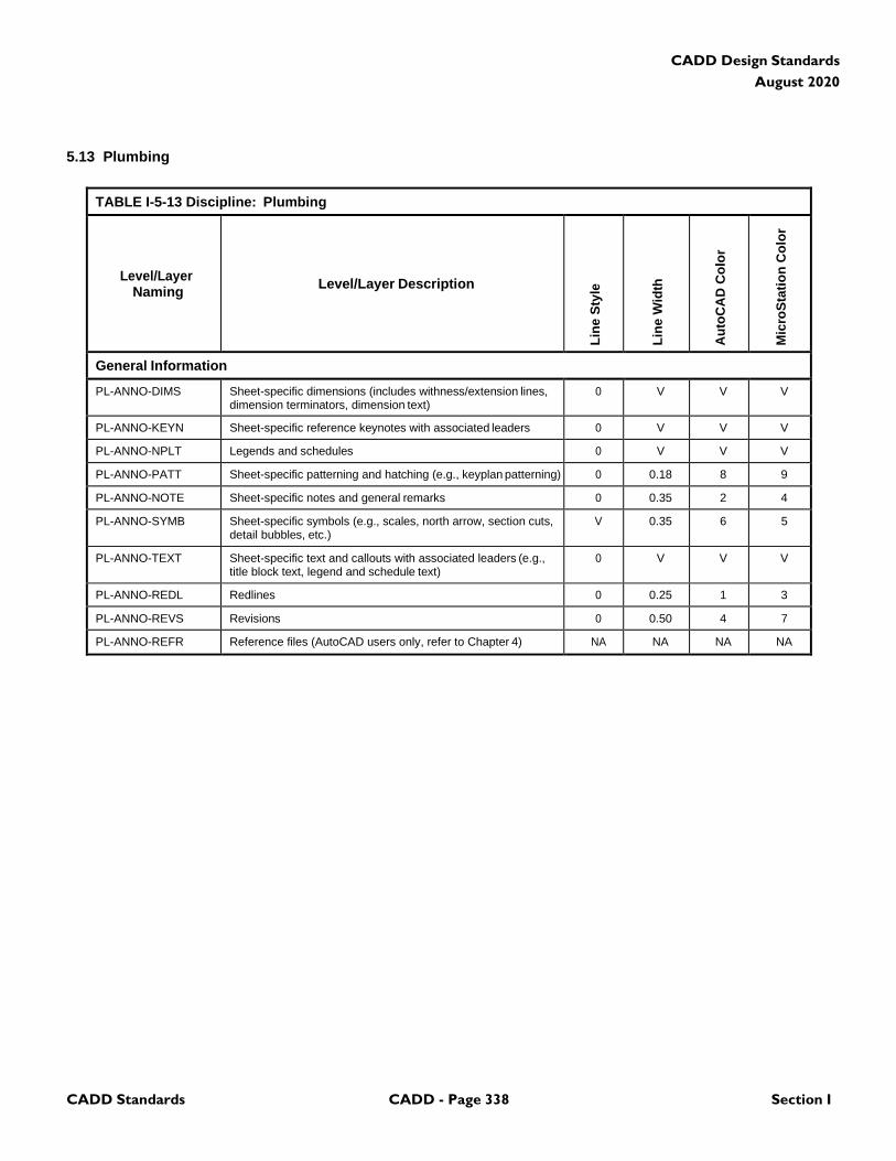
CADD Standards CADD - Page 338 Section I
CADD Design Standards
August 2020
5.13 Plumbing
TABLE I-5-13 Discipline: Plumbing
Level/Layer
Naming
Level/Layer Description
Lin
e S
tyle
Lin
e W
idth
Au
toC
AD
Co
lor
Mic
roS
tati
on
Co
lor
General Information
PL-ANNO-DIMS Sheet-specific dimensions (includes withness/extension lines, dimension terminators, dimension text)
0 V V V
PL-ANNO-KEYN Sheet-specific reference keynotes with associated leaders 0 V V V
PL-ANNO-NPLT Legends and schedules 0 V V V
PL-ANNO-PATT Sheet-specific patterning and hatching (e.g., keyplan patterning) 0 0.18 8 9
PL-ANNO-NOTE Sheet-specific notes and general remarks 0 0.35 2 4
PL-ANNO-SYMB Sheet-specific symbols (e.g., scales, north arrow, section cuts, detail bubbles, etc.)
V 0.35 6 5
PL-ANNO-TEXT Sheet-specific text and callouts with associated leaders (e.g., title block text, legend and schedule text)
0 V V V
PL-ANNO-REDL Redlines 0 0.25 1 3
PL-ANNO-REVS Revisions 0 0.50 4 7
PL-ANNO-REFR Reference files (AutoCAD users only, refer to Chapter 4) NA NA NA NA

CADD Standards CADD - Page 339 Section I
CADD Design Standards
August 2020
5.14 Mechanical
TABLE I-5-14 Discipline: Mechanical
Level/Layer
Naming
Level/Layer Description
Lin
e S
tyle
Lin
e W
idth
Au
toC
AD
Co
lor
Mic
roS
tati
on
Co
lor
General Information
ME-ANNO-DIMS Sheet-specific dimensions (includes withness/extension lines, dimension terminators, dimension text)
0 V V V
ME-ANNO-KEYN Sheet-specific reference keynotes with associated leaders 0 V V V
ME-ANNO-NPLT Legends and schedules 0 V V V
ME-ANNO-PATT Sheet-specific patterning and hatching (e.g., keyplan patterning) 0 0.18 8 9
ME-ANNO-NOTE Sheet-specific notes and general remarks 0 0.35 2 4
ME-ANNO-SYMB Sheet-specific symbols (e.g., scales, north arrow, section cuts, detail bubbles, etc.)
V 0.35 6 5
ME-ANNO-TEXT Sheet-specific text and callouts with associated leaders (e.g., title block text, legend and schedule text)
0 V V V
ME-ANNO-REDL Redlines 0 0.25 1 3
ME-ANNO-REVS Revisions 0 0.50 4 7
ME-ANNO-REFR Reference files (AutoCAD users only, refer to Chapter 4) NA NA NA NA
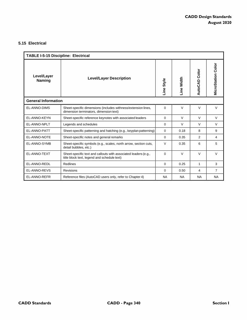
CADD Standards CADD - Page 340 Section I
CADD Design Standards
August 2020
5.15 Electrical
TABLE I-5-15 Discipline: Electrical
Level/Layer
Naming
Level/Layer Description
Lin
e S
tyle
Lin
e W
idth
Au
toC
AD
Co
lor
Mic
roS
tati
on
Co
lor
General Information
EL-ANNO-DIMS Sheet-specific dimensions (includes withness/extension lines, dimension terminators, dimension text)
0 V V V
EL-ANNO-KEYN Sheet-specific reference keynotes with associated leaders 0 V V V
EL-ANNO-NPLT Legends and schedules 0 V V V
EL-ANNO-PATT Sheet-specific patterning and hatching (e.g., keyplan patterning) 0 0.18 8 9
EL-ANNO-NOTE Sheet-specific notes and general remarks 0 0.35 2 4
EL-ANNO-SYMB Sheet-specific symbols (e.g., scales, north arrow, section cuts, detail bubbles, etc.)
V 0.35 6 5
EL-ANNO-TEXT Sheet-specific text and callouts with associated leaders (e.g., title block text, legend and schedule text)
0 V V V
EL-ANNO-REDL Redlines 0 0.25 1 3
EL-ANNO-REVS Revisions 0 0.50 4 7
EL-ANNO-REFR Reference files (AutoCAD users only, refer to Chapter 4) NA NA NA NA
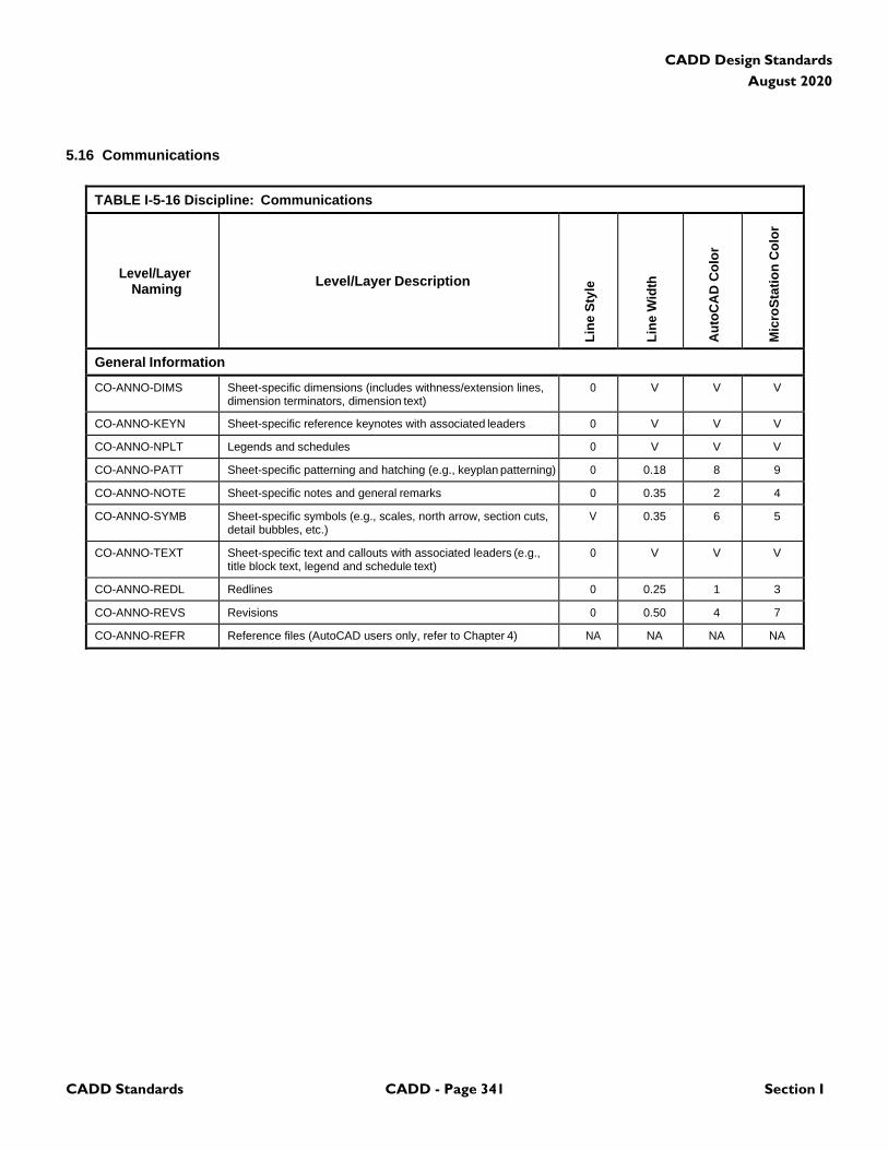
CADD Standards CADD - Page 341 Section I
CADD Design Standards
August 2020
5.16 Communications
TABLE I-5-16 Discipline: Communications
Level/Layer
Naming
Level/Layer Description
Lin
e S
tyle
Lin
e W
idth
Au
toC
AD
Co
lor
Mic
roS
tati
on
Co
lor
General Information
CO-ANNO-DIMS Sheet-specific dimensions (includes withness/extension lines, dimension terminators, dimension text)
0 V V V
CO-ANNO-KEYN Sheet-specific reference keynotes with associated leaders 0 V V V
CO-ANNO-NPLT Legends and schedules 0 V V V
CO-ANNO-PATT Sheet-specific patterning and hatching (e.g., keyplan patterning) 0 0.18 8 9
CO-ANNO-NOTE Sheet-specific notes and general remarks 0 0.35 2 4
CO-ANNO-SYMB Sheet-specific symbols (e.g., scales, north arrow, section cuts, detail bubbles, etc.)
V 0.35 6 5
CO-ANNO-TEXT Sheet-specific text and callouts with associated leaders (e.g., title block text, legend and schedule text)
0 V V V
CO-ANNO-REDL Redlines 0 0.25 1 3
CO-ANNO-REVS Revisions 0 0.50 4 7
CO-ANNO-REFR Reference files (AutoCAD users only, refer to Chapter 4) NA NA NA NA
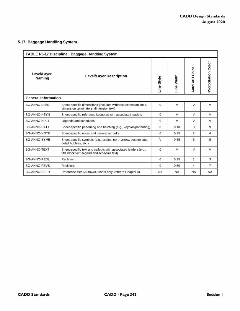
CADD Standards CADD - Page 342 Section I
CADD Design Standards
August 2020
5.17 Baggage Handling System
TABLE I-5-17 Discipline: Baggage Handling System
Level/Layer
Naming
Level/Layer Description
Lin
e S
tyle
Lin
e W
idth
Au
toC
AD
Co
lor
Mic
roS
tati
on
Co
lor
General Information
BG-ANNO-DIMS Sheet-specific dimensions (includes withness/extension lines, dimension terminators, dimension text)
0 V V V
BG-ANNO-KEYN Sheet-specific reference keynotes with associated leaders 0 V V V
BG-ANNO-NPLT Legends and schedules 0 V V V
BG-ANNO-PATT Sheet-specific patterning and hatching (e.g., keyplan patterning) 0 0.18 8 9
BG-ANNO-NOTE Sheet-specific notes and general remarks 0 0.35 2 4
BG-ANNO-SYMB Sheet-specific symbols (e.g., scales, north arrow, section cuts, detail bubbles, etc.)
V 0.35 6 5
BG-ANNO-TEXT Sheet-specific text and callouts with associated leaders (e.g., title block text, legend and schedule text)
0 V V V
BG-ANNO-REDL Redlines 0 0.25 1 3
BG-ANNO-REVS Revisions 0 0.50 4 7
BG-ANNO-REFR Reference files (AutoCAD users only, refer to Chapter 4) NA NA NA NA
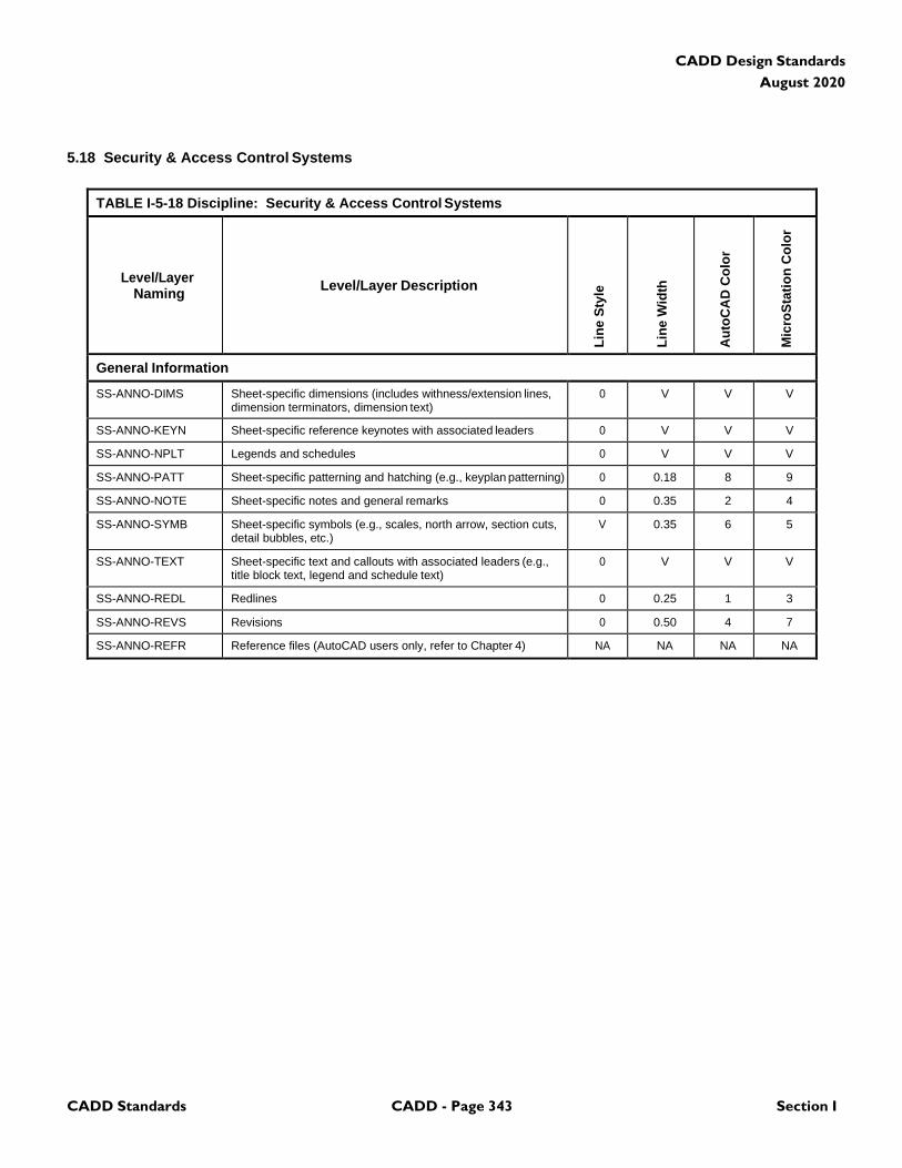
CADD Standards CADD - Page 343 Section I
CADD Design Standards
August 2020
5.18 Security & Access Control Systems
TABLE I-5-18 Discipline: Security & Access Control Systems
Level/Layer
Naming
Level/Layer Description
Lin
e S
tyle
Lin
e W
idth
Au
toC
AD
Co
lor
Mic
roS
tati
on
Co
lor
General Information
SS-ANNO-DIMS Sheet-specific dimensions (includes withness/extension lines, dimension terminators, dimension text)
0 V V V
SS-ANNO-KEYN Sheet-specific reference keynotes with associated leaders 0 V V V
SS-ANNO-NPLT Legends and schedules 0 V V V
SS-ANNO-PATT Sheet-specific patterning and hatching (e.g., keyplan patterning) 0 0.18 8 9
SS-ANNO-NOTE Sheet-specific notes and general remarks 0 0.35 2 4
SS-ANNO-SYMB Sheet-specific symbols (e.g., scales, north arrow, section cuts, detail bubbles, etc.)
V 0.35 6 5
SS-ANNO-TEXT Sheet-specific text and callouts with associated leaders (e.g., title block text, legend and schedule text)
0 V V V
SS-ANNO-REDL Redlines 0 0.25 1 3
SS-ANNO-REVS Revisions 0 0.50 4 7
SS-ANNO-REFR Reference files (AutoCAD users only, refer to Chapter 4) NA NA NA NA
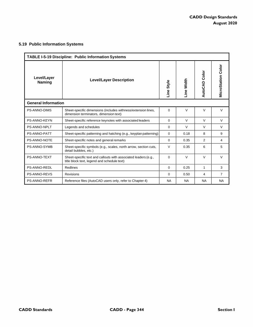
CADD Standards CADD - Page 344 Section I
CADD Design Standards
August 2020
5.19 Public Information Systems
TABLE I-5-19 Discipline: Public Information Systems
Level/Layer
Naming
Level/Layer Description
Lin
e S
tyle
Lin
e W
idth
Au
toC
AD
Co
lor
Mic
roS
tati
on
Co
lor
General Information
PS-ANNO-DIMS Sheet-specific dimensions (includes withness/extension lines, dimension terminators, dimension text)
0 V V V
PS-ANNO-KEYN Sheet-specific reference keynotes with associated leaders 0 V V V
PS-ANNO-NPLT Legends and schedules 0 V V V
PS-ANNO-PATT Sheet-specific patterning and hatching (e.g., keyplan patterning) 0 0.18 8 9
PS-ANNO-NOTE Sheet-specific notes and general remarks 0 0.35 2 4
PS-ANNO-SYMB Sheet-specific symbols (e.g., scales, north arrow, section cuts, detail bubbles, etc.)
V 0.35 6 5
PS-ANNO-TEXT Sheet-specific text and callouts with associated leaders (e.g., title block text, legend and schedule text)
0 V V V
PS-ANNO-REDL Redlines 0 0.25 1 3
PS-ANNO-REVS Revisions 0 0.50 4 7
PS-ANNO-REFR Reference files (AutoCAD users only, refer to Chapter 4) NA NA NA NA

CADD Standards CADD - Page 345 Section I
CADD Design Standards
August 2020
5.20 Aviation Information Systems
TABLE I-5-20 Discipline: Aviation Information Systems
Level/Layer
Naming
Level/Layer Description
Lin
e S
tyle
Lin
e W
idth
Au
toC
AD
Co
lor
Mic
roS
tati
on
Co
lor
General Information
AS-ANNO-DIMS Sheet-specific dimensions (includes withness/extension lines, dimension terminators, dimension text)
0 V V V
AS-ANNO-KEYN Sheet-specific reference keynotes with associated leaders 0 V V V
AS-ANNO-NPLT Legends and schedules 0 V V V
AS-ANNO-PATT Sheet-specific patterning and hatching (e.g., keyplan patterning) 0 0.18 8 9
AS-ANNO-NOTE Sheet-specific notes and general remarks 0 0.35 2 4
AS-ANNO-SYMB Sheet-specific symbols (e.g., scales, north arrow, section cuts, detail bubbles, etc.)
V 0.35 6 5
AS-ANNO-TEXT Sheet-specific text and callouts with associated leaders (e.g., title block text, legend and schedule text)
0 V V V
AS-ANNO-REDL Redlines 0 0.25 1 3
AS-ANNO-REVS Revisions 0 0.50 4 7
AS-ANNO-REFR Reference files (AutoCAD users only, refer to Chapter 4) NA NA NA NA

CADD Standards CADD - Page 346 Section I
CADD Design Standards
August 2020
5.21 Electronic Monitoring Systems
TABLE I-5-21 Discipline: Electronic Monitoring Systems
Level/Layer
Naming
Level/Layer Description
Lin
e S
tyle
Lin
e W
idth
Au
toC
AD
Co
lor
Mic
roS
tati
on
Co
lor
General Information
ES-ANNO-DIMS Sheet-specific dimensions (includes withness/extension lines, dimension terminators, dimension text)
0 V V V
ES-ANNO-KEYN Sheet-specific reference keynotes with associated leaders 0 V V V
ES-ANNO-NPLT Legends and schedules 0 V V V
ES-ANNO-PATT Sheet-specific patterning and hatching (e.g., keyplan patterning) 0 0.18 8 9
ES-ANNO-NOTE Sheet-specific notes and general remarks 0 0.35 2 4
ES-ANNO-SYMB Sheet-specific symbols (e.g., scales, north arrow, section cuts, detail bubbles, etc.)
V 0.35 6 5
ES-ANNO-TEXT Sheet-specific text and callouts with associated leaders (e.g., title block text, legend and schedule text)
0 V V V
ES-ANNO-REDL Redlines 0 0.25 1 3
ES-ANNO-REVS Revisions 0 0.50 4 7
ES-ANNO-REFR Reference files (AutoCAD users only, refer to Chapter 4) NA NA NA NA
CADD Standards CADD - Page 347 Section I
CADD Design Standards
August 2020
(This Page Blank)
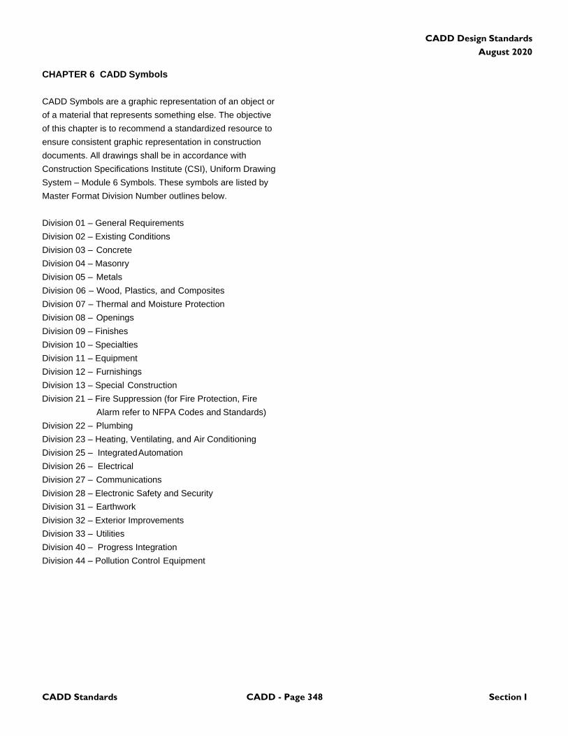
CADD Standards CADD - Page 348 Section I
CADD Design Standards
August 2020
CHAPTER 6 CADD Symbols
CADD Symbols are a graphic representation of an object or
of a material that represents something else. The objective
of this chapter is to recommend a standardized resource to
ensure consistent graphic representation in construction
documents. All drawings shall be in accordance with
Construction Specifications Institute (CSI), Uniform Drawing
System – Module 6 Symbols. These symbols are listed by
Master Format Division Number outlines below.
Division 01 – General Requirements
Division 02 – Existing Conditions
Division 03 – Concrete
Division 04 – Masonry
Division 05 – Metals
Division 06 – Wood, Plastics, and Composites
Division 07 – Thermal and Moisture Protection
Division 08 – Openings
Division 09 – Finishes
Division 10 – Specialties
Division 11 – Equipment
Division 12 – Furnishings
Division 13 – Special Construction
Division 21 – Fire Suppression (for Fire Protection, Fire
Alarm refer to NFPA Codes and Standards)
Division 22 – Plumbing
Division 23 – Heating, Ventilating, and Air Conditioning
Division 25 – Integrated Automation
Division 26 – Electrical
Division 27 – Communications
Division 28 – Electronic Safety and Security
Division 31 – Earthwork
Division 32 – Exterior Improvements
Division 33 – Utilities
Division 40 – Progress Integration
Division 44 – Pollution Control Equipment

CADD Standards CADD - Page 349 Section I
CADD Design Standards
August 2020
(This Page Blank)
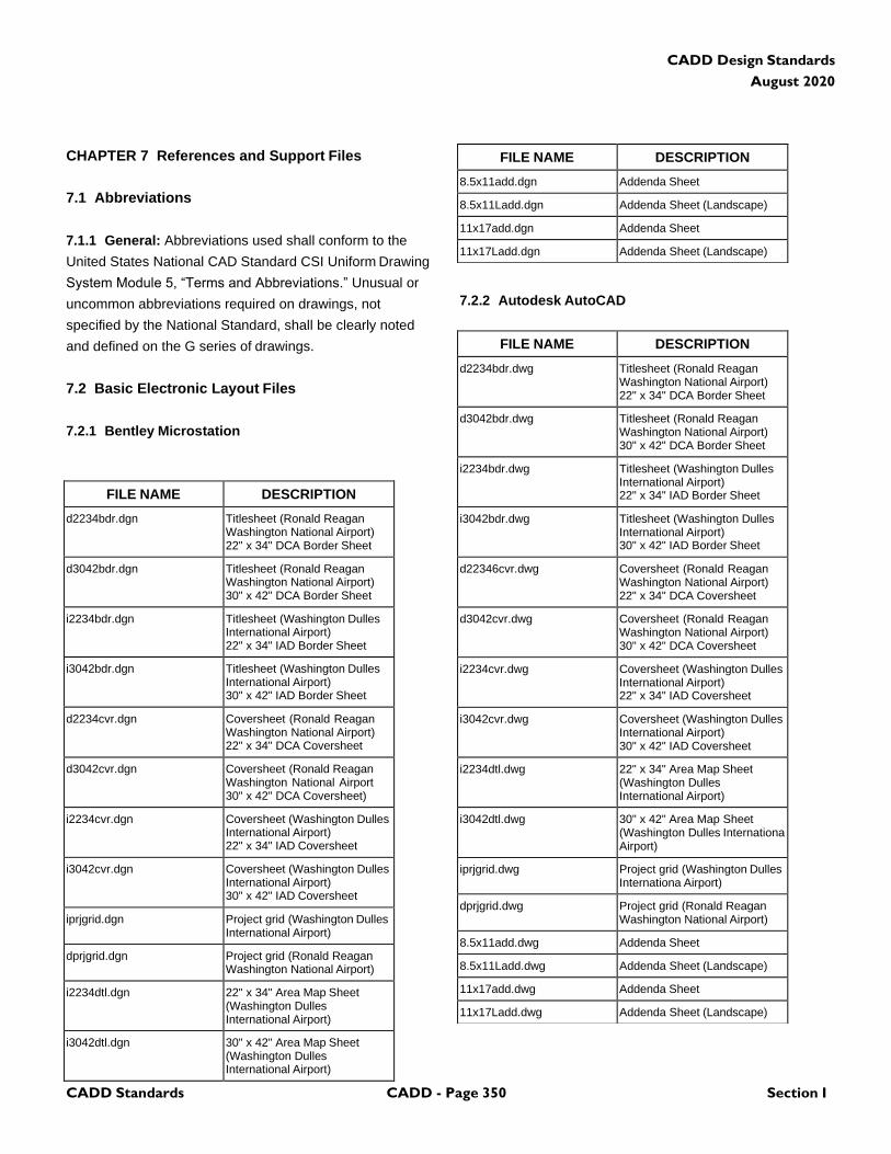
CADD Standards CADD - Page 350 Section I
CADD Design Standards
August 2020
CHAPTER 7 References and Support Files
7.1 Abbreviations
7.1.1 General: Abbreviations used shall conform to the
United States National CAD Standard CSI Uniform Drawing
System Module 5, “Terms and Abbreviations.” Unusual or
uncommon abbreviations required on drawings, not
specified by the National Standard, shall be clearly noted
and defined on the G series of drawings.
7.2 Basic Electronic Layout Files
7.2.1 Bentley Microstation
7.2.2 Autodesk AutoCAD
FILE NAME DESCRIPTION
d2234bdr.dgn Titlesheet (Ronald Reagan Washington National Airport) 22" x 34" DCA Border Sheet
d3042bdr.dgn Titlesheet (Ronald Reagan Washington National Airport) 30" x 42" DCA Border Sheet
i2234bdr.dgn Titlesheet (Washington Dulles International Airport) 22" x 34" IAD Border Sheet
i3042bdr.dgn Titlesheet (Washington Dulles International Airport) 30" x 42" IAD Border Sheet
d2234cvr.dgn Coversheet (Ronald Reagan Washington National Airport) 22" x 34" DCA Coversheet
d3042cvr.dgn Coversheet (Ronald Reagan Washington National Airport 30" x 42" DCA Coversheet)
i2234cvr.dgn Coversheet (Washington Dulles International Airport) 22" x 34" IAD Coversheet
i3042cvr.dgn Coversheet (Washington Dulles International Airport) 30" x 42" IAD Coversheet
iprjgrid.dgn Project grid (Washington Dulles International Airport)
dprjgrid.dgn Project grid (Ronald Reagan Washington National Airport)
i2234dtl.dgn 22" x 34" Area Map Sheet (Washington Dulles International Airport)
i3042dtl.dgn 30" x 42" Area Map Sheet (Washington Dulles International Airport)
FILE NAME DESCRIPTION
8.5x11add.dgn Addenda Sheet
8.5x11Ladd.dgn Addenda Sheet (Landscape)
11x17add.dgn Addenda Sheet
11x17Ladd.dgn Addenda Sheet (Landscape)
FILE NAME DESCRIPTION
d2234bdr.dwg Titlesheet (Ronald Reagan Washington National Airport) 22" x 34" DCA Border Sheet
d3042bdr.dwg Titlesheet (Ronald Reagan Washington National Airport) 30" x 42" DCA Border Sheet
i2234bdr.dwg Titlesheet (Washington Dulles International Airport) 22" x 34" IAD Border Sheet
i3042bdr.dwg Titlesheet (Washington Dulles International Airport) 30" x 42" IAD Border Sheet
d22346cvr.dwg Coversheet (Ronald Reagan Washington National Airport) 22" x 34" DCA Coversheet
d3042cvr.dwg Coversheet (Ronald Reagan Washington National Airport) 30" x 42" DCA Coversheet
i2234cvr.dwg Coversheet (Washington Dulles International Airport) 22" x 34" IAD Coversheet
i3042cvr.dwg Coversheet (Washington Dulles International Airport) 30" x 42" IAD Coversheet
i2234dtl.dwg 22" x 34" Area Map Sheet (Washington Dulles International Airport)
i3042dtl.dwg 30" x 42" Area Map Sheet (Washington Dulles Internationa Airport)
iprjgrid.dwg Project grid (Washington Dulles Internationa Airport)
dprjgrid.dwg Project grid (Ronald Reagan Washington National Airport)
8.5x11add.dwg Addenda Sheet
8.5x11Ladd.dwg Addenda Sheet (Landscape)
11x17add.dwg Addenda Sheet
11x17Ladd.dwg Addenda Sheet (Landscape)
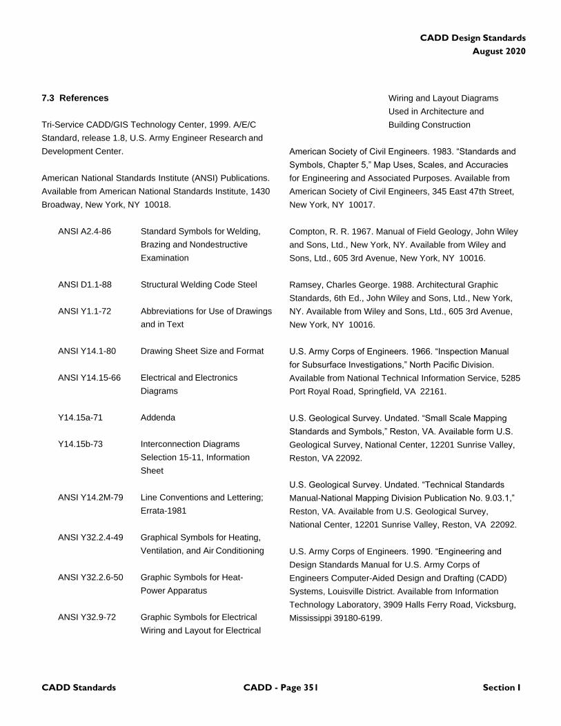
CADD Standards CADD - Page 351 Section I
CADD Design Standards
August 2020
7.3 References
Tri-Service CADD/GIS Technology Center, 1999. A/E/C
Standard, release 1.8, U.S. Army Engineer Research and
Development Center.
American National Standards Institute (ANSI) Publications.
Available from American National Standards Institute, 1430
Broadway, New York, NY 10018.
ANSI A2.4-86 Standard Symbols for Welding,
Brazing and Nondestructive
Examination
ANSI D1.1-88 Structural Welding Code Steel
ANSI Y1.1-72 Abbreviations for Use of Drawings
and in Text
ANSI Y14.1-80 Drawing Sheet Size and Format
ANSI Y14.15-66 Electrical and Electronics
Diagrams
Y14.15a-71 Addenda
Y14.15b-73 Interconnection Diagrams
Selection 15-11, Information
Sheet
ANSI Y14.2M-79 Line Conventions and Lettering;
Errata-1981
ANSI Y32.2.4-49 Graphical Symbols for Heating,
Ventilation, and Air Conditioning
ANSI Y32.2.6-50 Graphic Symbols for Heat-
Power Apparatus
ANSI Y32.9-72 Graphic Symbols for Electrical
Wiring and Layout for Electrical
Wiring and Layout Diagrams
Used in Architecture and
Building Construction
American Society of Civil Engineers. 1983. “Standards and
Symbols, Chapter 5,” Map Uses, Scales, and Accuracies
for Engineering and Associated Purposes. Available from
American Society of Civil Engineers, 345 East 47th Street,
New York, NY 10017.
Compton, R. R. 1967. Manual of Field Geology, John Wiley
and Sons, Ltd., New York, NY. Available from Wiley and
Sons, Ltd., 605 3rd Avenue, New York, NY 10016.
Ramsey, Charles George. 1988. Architectural Graphic
Standards, 6th Ed., John Wiley and Sons, Ltd., New York,
NY. Available from Wiley and Sons, Ltd., 605 3rd Avenue,
New York, NY 10016.
U.S. Army Corps of Engineers. 1966. “Inspection Manual
for Subsurface Investigations,” North Pacific Division.
Available from National Technical Information Service, 5285
Port Royal Road, Springfield, VA 22161.
U.S. Geological Survey. Undated. “Small Scale Mapping
Standards and Symbols,” Reston, VA. Available form U.S.
Geological Survey, National Center, 12201 Sunrise Valley,
Reston, VA 22092.
U.S. Geological Survey. Undated. “Technical Standards
Manual-National Mapping Division Publication No. 9.03.1,”
Reston, VA. Available from U.S. Geological Survey,
National Center, 12201 Sunrise Valley, Reston, VA 22092.
U.S. Army Corps of Engineers. 1990. “Engineering and
Design Standards Manual for U.S. Army Corps of
Engineers Computer-Aided Design and Drafting (CADD)
Systems, Louisville District. Available from Information
Technology Laboratory, 3909 Halls Ferry Road, Vicksburg,
Mississippi 39180-6199.
CADD Design Standards
August 2020
CADD Standards GIS - Page 352 Section II
(This Page Blank)
CADD Design Standards
August 2020
CADD Standards GIS - Page 353 Section II
SECTION II: GIS
CHAPTER 1 Geographic Information Systems (GIS)
Standards and Submittal Requirements
The Authority has established an Enterprise GIS program,
referred to herein as the “MWAA Enterprise GIS”. The
MWAA GIS is intended to support numerous different
business processes, ranging from (and not limited to)
Enterprise Asset Management, lease and tenant
management, computerized maintenance management
(CMMS), landside and airside operations, public safety,
master planning and environmental management.
To support these and other Authority business processes,
the MWAA GIS must include an accurate and complete
representation of facility infrastructure and assets across
both airport campuses and the Dulles Corridor Enterprise
(DCE). A key strategy for ensuring accuracy and
completeness of the map (spatial) data within the MWAA
GIS database is to integrate data from design and
construction activities, upon submittal to the Authority
Program Manager by the A/E and/or contractor or the GIS
Division.
The A/E shall coordinate with the MWAA GIS Supervisor to
ensure that all GIS work and submittals are completed in
compliance with the following:
1.1 Applicability:
The A/E is required to provide a GIS submittal matching the
CADD design drawings at the final design submittal
milestone and, if applicable, when conformed sets are
submitted following the final design submittal milestone.
The contractor is required to provide a GIS submittal
matching the CADD record (or, if applicable, as-built)
drawings. This requirement applies to the following design
and construction activities:
A. Capital Construction (CCP) design projects.
B. Capital Operations and Maintenance Improvement
Program (COMIP) design projects.
C. Large tenant design projects resulting in new
facilities, buildings or other structures.
D. Airline and concession tenant projects in the interior
of terminals, concourses and other buildings.
1.2 Creating GIS Features from CADD Model Files:
When providing a GIS submittal the A/E or contractor shall
provide spatial data matching the features as rendered in
the CADD drawing model files (containing the physical
facility or asset components; buildings, aprons, runways,
roads, fences, etc.), in real-world coordinates as further
described in Section 8.3.1.
The A/E and contractor shall not create GIS submittals
separately from their CADD submittals unless it is not a
Design/Construction project. GIS submittals shall be created
by making a copy of features in the CADD model files and
converting those features to GIS format, to ensure a match
between the CADD and GIS submittals.
Sheet files for plotting (including borders, title blocks, etc.)
shall not be included in the GIS submittal.
1.3 Structure and Organization of GIS Submittals:
GIS submittals shall adhere to the following additional
structural requirements and standards. Project specific
requirements based on the underling standards, if any, will
be provided in the contract scope of work:
1.3.1 File Format:
All GIS data shall be submitted to the Authority in
Environmental Systems Research Institute (ESRI) ArcGIS
10.5 compatible File Geodatabase. One shapefile will be
provided for each required GIS layer/feature class (see
Section 8.3.3 below).
1.3.2 Coordinate system:
1. Coordinate System and Datum
All GIS deliverables should be registered to the Virginia State
Plane North coordinate system and projection. Additional
requirements for registering spatial data in the MWAA GIS
include:
CADD Design Standards
August 2020
CADD Standards GIS - Page 354 Section II
A. Coordinate units—geographic coordinates
will be recorded in survey feet for both horizontal and
vertical coordinate measurements.
B. Horizontal datum and ellipsoid—
geographic coordinates are based on the North
American Datum of 1983 (NAD83) State Planes
Virginia North Zone.
C. Vertical datum—elevations for Airport control
documentation are based on the North American
Vertical Datum of 1988 (NAVD 88).
The accompanying CADD drawings shall continue to be
submitted using decimal coordinates and the Airport
Coordinate System (ACS) as described in Section 2.4.3.
1.3.3 Required GIS Submittal Content:
At the beginning of each design or construction project the
Authority Project Manager will provide the A/E or contractor
with an indication of the geographic “footprint” (or limits) for
the GIS deliverable and will also indicate which layers in the
MWAA GIS or FAA Airports GIS Database Dictionaries (see
Section 8.3.4) will be required for submittal.
1.3.4 Layer/Feature Class Assignments:
GIS layers, or feature classes, are analogous to overlays in
manual drafting systems and to layer/levels within a CADD
drawing. Each GIS layer/feature class contains a logical
grouping of features within a common feature type (e.g.,
buildings, roads, aprons, etc.). GIS submittals will be
organized using both layering schemes, depending on the
nature of the project and delivery milestone.
1.3.4.1 MWAA GIS Database Dictionary:
In all cases, the GIS submittal for final design plans shall be
organized using the layers/feature classes given at the
beginning of the project as a MWAA GIS Database
Template and as defined in the Database Dictionary
(defining the layers/feature classes in the MWAA GIS and
the definitions indicating what features are included in each
feature class).
1.3.4.2 Federal Aviation Administration (FAA) Airports
GIS Database Dictionary:
The Federal Aviation Administration (FAA) Advisory Circular
(AC) 150/5300-18C (signed May 2009) requires submittal of
spatial data for design projects paid for in part or in full by
FAA Airport Improvement Program (AIP) or Passenger
Facility Charge (PFC) grant funds. AC 150/5300-18 includes
information on the FAA Airports GIS database dictionary.
A. For projects funded in part or in full by FAA AIP or
PFC grant funds, the GIS submittal accompanying
record drawings at the end of the construction phase
shall be organized using the layers/feature classes as
defined in the most current version of the FAA Airports
GIS Database Dictionary in FAA AC 150/5300-18.
B. For projects funded in part or in full by FAA AIP or
PFC grant funds, the GIS submittal shall be
accompanied by a Survey Plan and Spatial Data
Collection Quality Control (QC) Plan as required by and
defined within the most current version of the FAA AC
150/5300-18.
C. For projects not funded in part or in full by FAA AIP
or PFC grant funds, the GIS submittal accompanying
record drawings at the end of the construction phase
shall be organized using the MWAA GIS Database
Dictionary, in a fashion similar to the GIS submittal at
the final design milestone.
1.3.5 Attribution:
Each feature in each layer/level of the GIS submittal will
contain a number of associated attributes (stored in the
ESRI shapefile). The following attributes are required as
part of each GIS submittal:
A. GIS Submittals organized using the MWAA GIS
Database Dictionary: For all GIS submittals at the final
design milestone and for GIS submittals accompanying
record drawings at the end of the construction phase
where no FAA submittal is required, each layer/feature
class will include required attributes as per the MWAA
GIS Database Dictionary. The MWAA GIS Database
Dictionary indicates required attributes, optional
attributes and in some cases valid attribute values.
CADD Design Standards
August 2020
CADD Standards GIS - Page 355 Section II
B. GIS Submittals organized using the FAA Airport GIS
Database Dictionary: For GIS submittals accompanying
record drawings at the end of the construction phase,
where FAA submittal is required, each layer/feature
class will include required attributes as per the FAA
Airports GIS Database Dictionary (included in the most
current version of the FAA AC 150/5300-18) and a set
of additional attributes from the MWAA GIS Database
Schema and Dictionary.
The construction contract scope of work will indicate which
attributes from the MWAA GIS Database Dictionary shall be
included in addition to FAA-required attributes.
Like the MWAA GIS Database Dictionary, the FAA Airports
GIS Database Dictionary indicates required and optional
attributes as well as valid attribute values were appropriate.
1.3.6 Metadata:
Each GIS submittal will include layer-level and feature-level
metadata. The following metadata are required as part of
each GIS submittal:
J. GIS Submittals organized using the MWAA GIS
Database Dictionary: For all GIS submittals at the final
design milestone and for GIS submittals accompanying
record drawings at the end of the construction phase
where no FAA submittal is required, each GIS submittal
layer/feature class shall include metadata as defined in
the MWAA GIS Metadata Specification.
K. GIS Submittals organized using the FAA Airport
GIS Database Dictionary: For GIS submittals
accompanying record drawings at the end of the
construction phase, where FAA submittal is required,
those GIS submittals will include metadata as defined
in the FAA Airports GIS Database Dictionary
(included in the most current version of the FAA AC
150/5300-18) and metadata as defined in the MWAA
GIS Metadata Specification.
1.3.7 Additional notes on MWAA GIS Database
Dictionary and Metadata Specification:
L. The MWAA GIS Database Schema, Data
Dictionary and Metadata Specification will be
provided to the A/E and/or contractor upon
contract award, and can be provided in advance of
award upon request.
M. The MWAA GIS Database Dictionary includes a
“mapping” (association) of layer/levels in the Authority
CADD Design Standard to the layer/feature classes in
the MWAA GIS Database Dictionary. This will assist
A/Es and contractors in creating GIS submittals from
CADD design drawings and record drawings.
1.4 Requirements for Ensuring High Quality GIS
Deliverables
This section provides a set of required practices A/Es and
contractors must follow when building and preparing CADD
files to facilitate GIS integration. These practices are
adopted from industry best practice recommendations for
ensuring proper CADD and GIS coordination and
integration.
The Authority and its Program Manager reserve the right to
perform quality control checks to ensure CADD content is
compiled in accordance with these practices to ensure high-
quality GIS deliverables.
By adhering to a set of required practices for building CADD
files:
N. A/Es and contractors will find the effort to create the
associated GIS deliverables will be less than that when
not applying a set of required practices. Additionally,
the process to convert CADD data to GIS format for
delivery to the Authority will be repeatable and
understandable by all stakeholders.
O. A/Es and contractors are more likely to have the
Authority accept first-time CADD and GIS submittals.
P. The Authority is better assured that the GIS
deliverables derived from CADD drawings contain
spatial data that are properly structured and of better
and more consistent quality.
1.4.1 Complex vs. Simple Geometry Types:
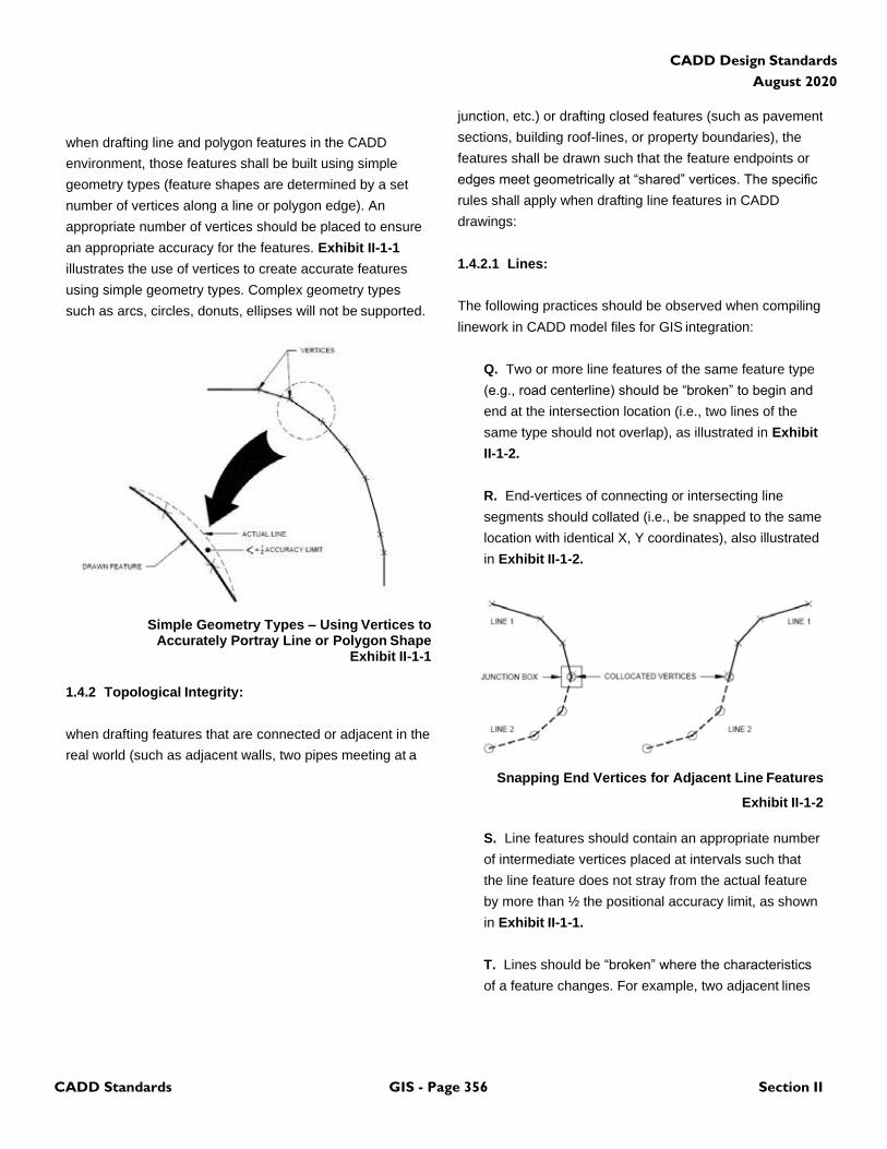
CADD Design Standards
August 2020
CADD Standards GIS - Page 356 Section II
when drafting line and polygon features in the CADD
environment, those features shall be built using simple
geometry types (feature shapes are determined by a set
number of vertices along a line or polygon edge). An
appropriate number of vertices should be placed to ensure
an appropriate accuracy for the features. Exhibit II-1-1
illustrates the use of vertices to create accurate features
using simple geometry types. Complex geometry types
such as arcs, circles, donuts, ellipses will not be supported.
Simple Geometry Types – Using Vertices to Accurately Portray Line or Polygon Shape
Exhibit II-1-1
1.4.2 Topological Integrity:
when drafting features that are connected or adjacent in the
real world (such as adjacent walls, two pipes meeting at a
junction, etc.) or drafting closed features (such as pavement
sections, building roof-lines, or property boundaries), the
features shall be drawn such that the feature endpoints or
edges meet geometrically at “shared” vertices. The specific
rules shall apply when drafting line features in CADD
drawings:
1.4.2.1 Lines:
The following practices should be observed when compiling
linework in CADD model files for GIS integration:
Q. Two or more line features of the same feature type
(e.g., road centerline) should be “broken” to begin and
end at the intersection location (i.e., two lines of the
same type should not overlap), as illustrated in Exhibit
II-1-2.
R. End-vertices of connecting or intersecting line
segments should collated (i.e., be snapped to the same
location with identical X, Y coordinates), also illustrated
in Exhibit II-1-2.
Snapping End Vertices for Adjacent Line Features
Exhibit II-1-2
S. Line features should contain an appropriate number
of intermediate vertices placed at intervals such that
the line feature does not stray from the actual feature
by more than ½ the positional accuracy limit, as shown
in Exhibit II-1-1.
T. Lines should be “broken” where the characteristics
of a feature changes. For example, two adjacent lines
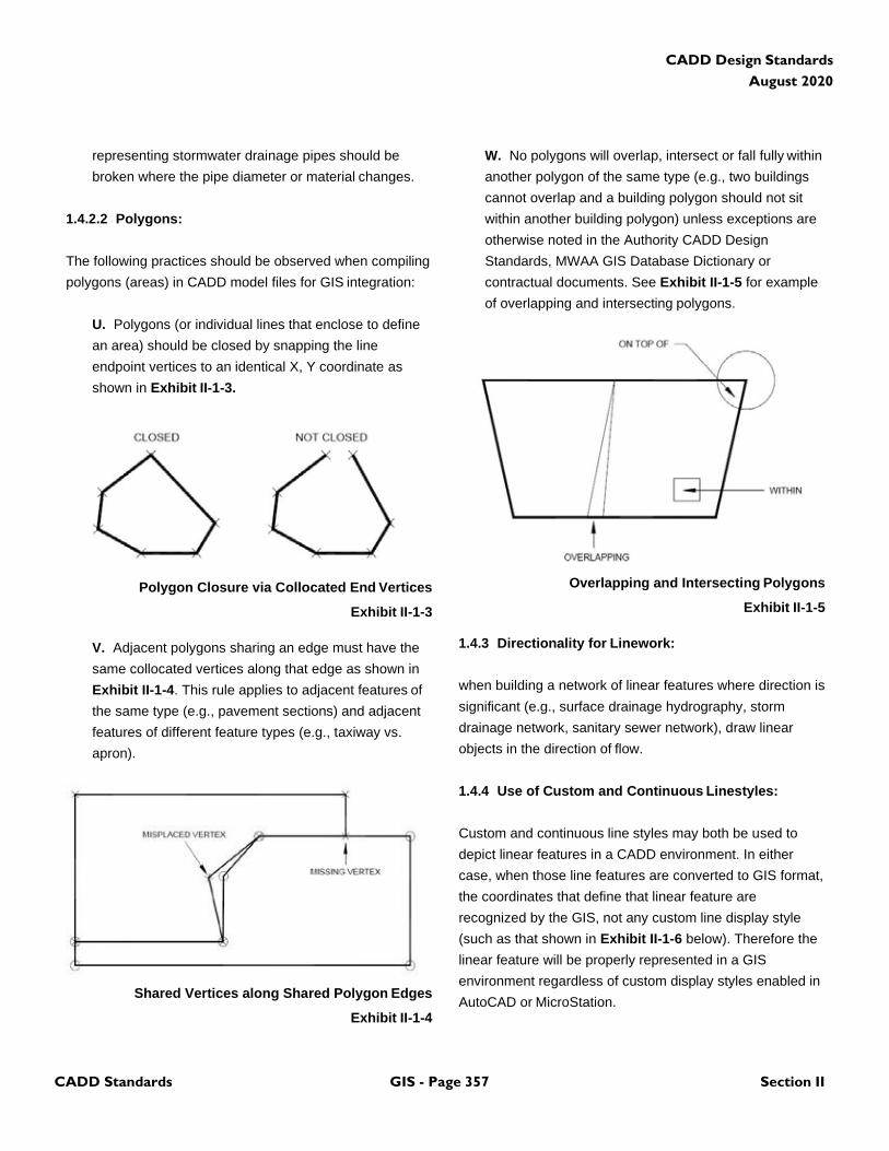
CADD Design Standards
August 2020
CADD Standards GIS - Page 357 Section II
representing stormwater drainage pipes should be
broken where the pipe diameter or material changes.
1.4.2.2 Polygons:
The following practices should be observed when compiling
polygons (areas) in CADD model files for GIS integration:
U. Polygons (or individual lines that enclose to define
an area) should be closed by snapping the line
endpoint vertices to an identical X, Y coordinate as
shown in Exhibit II-1-3.
Polygon Closure via Collocated End Vertices
Exhibit II-1-3
V. Adjacent polygons sharing an edge must have the
same collocated vertices along that edge as shown in
Exhibit II-1-4. This rule applies to adjacent features of
the same type (e.g., pavement sections) and adjacent
features of different feature types (e.g., taxiway vs.
apron).
Shared Vertices along Shared Polygon Edges
Exhibit II-1-4
W. No polygons will overlap, intersect or fall fully within
another polygon of the same type (e.g., two buildings
cannot overlap and a building polygon should not sit
within another building polygon) unless exceptions are
otherwise noted in the Authority CADD Design
Standards, MWAA GIS Database Dictionary or
contractual documents. See Exhibit II-1-5 for example
of overlapping and intersecting polygons.
Overlapping and Intersecting Polygons
Exhibit II-1-5
1.4.3 Directionality for Linework:
when building a network of linear features where direction is
significant (e.g., surface drainage hydrography, storm
drainage network, sanitary sewer network), draw linear
objects in the direction of flow.
1.4.4 Use of Custom and Continuous Linestyles:
Custom and continuous line styles may both be used to
depict linear features in a CADD environment. In either
case, when those line features are converted to GIS format,
the coordinates that define that linear feature are
recognized by the GIS, not any custom line display style
(such as that shown in Exhibit II-1-6 below). Therefore the
linear feature will be properly represented in a GIS
environment regardless of custom display styles enabled in
AutoCAD or MicroStation.
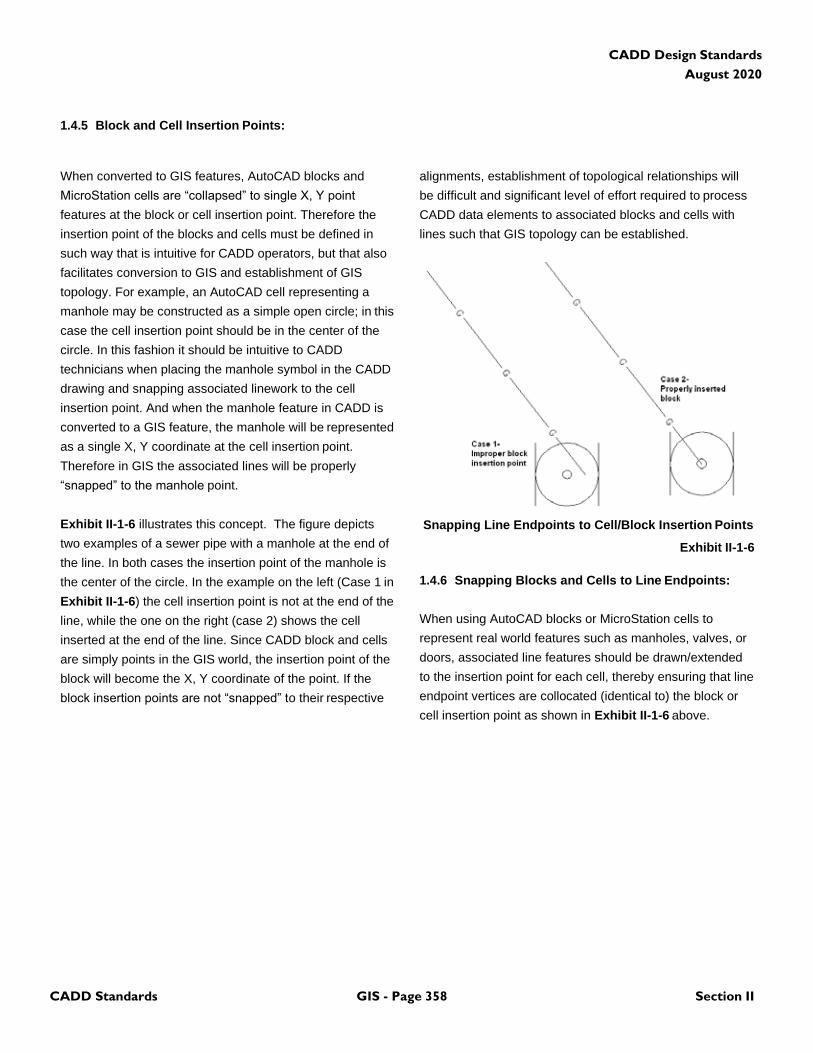
CADD Design Standards
August 2020
CADD Standards GIS - Page 358 Section II
1.4.5 Block and Cell Insertion Points:
When converted to GIS features, AutoCAD blocks and
MicroStation cells are “collapsed” to single X, Y point
features at the block or cell insertion point. Therefore the
insertion point of the blocks and cells must be defined in
such way that is intuitive for CADD operators, but that also
facilitates conversion to GIS and establishment of GIS
topology. For example, an AutoCAD cell representing a
manhole may be constructed as a simple open circle; in this
case the cell insertion point should be in the center of the
circle. In this fashion it should be intuitive to CADD
technicians when placing the manhole symbol in the CADD
drawing and snapping associated linework to the cell
insertion point. And when the manhole feature in CADD is
converted to a GIS feature, the manhole will be represented
as a single X, Y coordinate at the cell insertion point.
Therefore in GIS the associated lines will be properly
“snapped” to the manhole point.
Exhibit II-1-6 illustrates this concept. The figure depicts
two examples of a sewer pipe with a manhole at the end of
the line. In both cases the insertion point of the manhole is
the center of the circle. In the example on the left (Case 1 in
Exhibit II-1-6) the cell insertion point is not at the end of the
line, while the one on the right (case 2) shows the cell
inserted at the end of the line. Since CADD block and cells
are simply points in the GIS world, the insertion point of the
block will become the X, Y coordinate of the point. If the
block insertion points are not “snapped” to their respective
alignments, establishment of topological relationships will
be difficult and significant level of effort required to process
CADD data elements to associated blocks and cells with
lines such that GIS topology can be established.
Snapping Line Endpoints to Cell/Block Insertion Points
Exhibit II-1-6
1.4.6 Snapping Blocks and Cells to Line Endpoints:
When using AutoCAD blocks or MicroStation cells to
represent real world features such as manholes, valves, or
doors, associated line features should be drawn/extended
to the insertion point for each cell, thereby ensuring that line
endpoint vertices are collocated (identical to) the block or
cell insertion point as shown in Exhibit II-1-6 above.
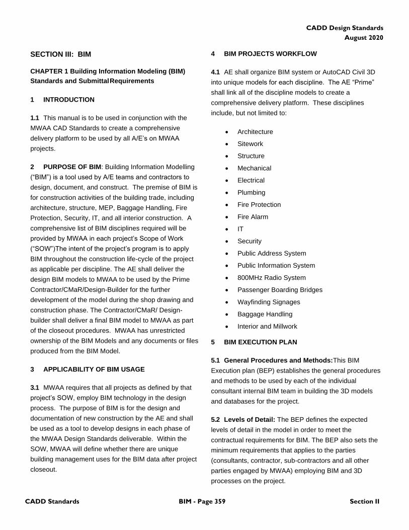
CADD Design Standards
August 2020
CADD Standards BIM - Page 359 Section II
SECTION III: BIM
CHAPTER 1 Building Information Modeling (BIM)
Standards and Submittal Requirements
1 INTRODUCTION
1.1 This manual is to be used in conjunction with the
MWAA CAD Standards to create a comprehensive
delivery platform to be used by all A/E’s on MWAA
projects.
2 PURPOSE OF BIM: Building Information Modelling
(“BIM”) is a tool used by A/E teams and contractors to
design, document, and construct. The premise of BIM is
for construction activities of the building trade, including
architecture, structure, MEP, Baggage Handling, Fire
Protection, Security, IT, and all interior construction. A
comprehensive list of BIM disciplines required will be
provided by MWAA in each project’s Scope of Work
(“SOW”)The intent of the project’s program is to apply
BIM throughout the construction life-cycle of the project
as applicable per discipline. The AE shall deliver the
design BIM models to MWAA to be used by the Prime
Contractor/CMaR/Design-Builder for the further
development of the model during the shop drawing and
construction phase. The Contractor/CMaR/ Design-
builder shall deliver a final BIM model to MWAA as part
of the closeout procedures. MWAA has unrestricted
ownership of the BIM Models and any documents or files
produced from the BIM Model.
3 APPLICABILITY OF BIM USAGE
3.1 MWAA requires that all projects as defined by that
project’s SOW, employ BIM technology in the design
process. The purpose of BIM is for the design and
documentation of new construction by the AE and shall
be used as a tool to develop designs in each phase of
the MWAA Design Standards deliverable. Within the
SOW, MWAA will define whether there are unique
building management uses for the BIM data after project
closeout.
4 BIM PROJECTS WORKFLOW
4.1 AE shall organize BIM system or AutoCAD Civil 3D
into unique models for each discipline. The AE “Prime”
shall link all of the discipline models to create a
comprehensive delivery platform. These disciplines
include, but not limited to:
• Architecture
• Sitework
• Structure
• Mechanical
• Electrical
• Plumbing
• Fire Protection
• Fire Alarm
• IT
• Security
• Public Address System
• Public Information System
• 800MHz Radio System
• Passenger Boarding Bridges
• Wayfinding Signages
• Baggage Handling
• Interior and Millwork
5 BIM EXECUTION PLAN
5.1 General Procedures and Methods:This BIM
Execution plan (BEP) establishes the general procedures
and methods to be used by each of the individual
consultant internal BIM team in building the 3D models
and databases for the project.
5.2 Levels of Detail: The BEP defines the expected
levels of detail in the model in order to meet the
contractual requirements for BIM. The BEP also sets the
minimum requirements that applies to the parties
(consultants, contractor, sub-contractors and all other
parties engaged by MWAA) employing BIM and 3D
processes on the project.
CADD Design Standards
August 2020
CADD Standards BIM - Page 360 Section II
The BEP is a living document for the duration of the
project. As this is the case, it will be periodically
updated, and issued accordingly.
5.3 Shared Workflows: The purpose of this document
is to define and describe BIM shared workflows on this
project. It covers standards, modelling scope and
exchange protocols among team members. Refer to
contractual documents for specific information regarding
project content, delivery methods and scope of work.
5.4 BIM Execution Plan Requirements: AE shall, at
the outset of the project, produce a project-specific BIM
Execution Plan. The plan should include:
• Description of the Project Scope
• Key Coordinates of the Project, per MWAA
survey data
• Key Floor Elevations and Levels per the vertical
datum set by MWAA
• Description of which project components will be
modelled in BIM, i.e. exclusions for elements in
3D Civil
• BIM Roles and Responsibilities of the AE
o Provide a list of Firms on the Project
provide BIM data
o Define whether the user is a BIM Model
Manager (creating a BIM model per
discipline) or a Discipline BIM Project
Lead (supplying 2D or 3D CAD info for
insertion into the BIM model)
o Key contact for the BIM system
• Roles and Responsibilities of Key BIM Contacts
o BIM Model Manager
▪ Leads the development of
models in accordance with the
BEP
▪ Facilitates transfer of info and
file sharing
▪ Leads the BIM coordination
and clash detection effort
o Discipline BIM Project Lead
▪ Act as contact for team
• Project Software Version. Define the version of
the following software to be used on the project
based on coordination with MWAA:
o Autodesk Civil 3D. Used primarily for civil
work with outputs in .dwg format.
o Autodesk Navisworks. Used primarily for
clash detection.
o Autodesk Revit. Used primarily for design
creation and documentation with output
in .rvt format.
• Coordination schedule and approach to resolving
conflicts
• Shared Workflows:
o Data Exchange. Describe how often
models will be shared amongst team
members and the mechanism for sharing
(Sharepoint, FTP, etc.)
o Clash Coordination Process
• Project Setup:
o Project Location and Shared Coordinates
o Workset structure and naming
o File Naming structure for each discipline
model
o Shared Levels and Grids
o Phasing (if required)
o Project Parameters. Based on the
project’s SOW, MWAA may choose to
require the AE to embed data into the
BIM platform for maintaining the
facilities. If MWAA chooses to utilize
BIM data for Building Management
System (BMS) interface, project
parameters must be addressed. Asset
data shall be compatible with MWAA
Computerized Maintenance
Management System.
• Project Standards
o Project Packaging. If a project is to be
delivered “fast-track” or with separate
packages per discipline, AE to develop a
structure for creating parameters within
Revit. The package information shall be
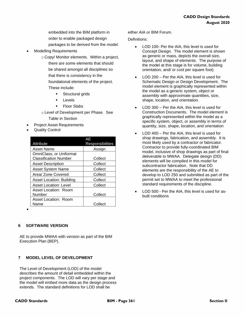
CADD Design Standards
August 2020
CADD Standards BIM - Page 361 Section II
embedded into the BIM platform in
order to enable packaged design
packages to be derived from the model.
• Modelling Requirements
o Copy/ Monitor elements. Within a project,
there are some elements that should
be shared amongst all disciplines so
that there is consistency in the
foundational elements of the project.
These include:
▪ Structural grids
▪ Levels
▪ Floor Slabs
o Level of Development per Phase. See
Table in Section
• Project Asset Requirements
• Quality Control
Attribute AE Responsibilities
Asset Name Assign
OmniClass, or Uniformat Classification Number Collect
Asset Description Collect
Asset System Name Collect
Area/ Zone Covered Collect
Asset Location: Building Collect
Asset Location: Level Collect
Asset Location: Room Number Collect
Asset Location: Room Name Collect
•
6 SOFTWARE VERSION
AE to provide MWAA with version as part of the BIM Execution Plan (BEP).
7 MODEL LEVEL OF DEVELOPMENT
The Level of Development (LOD) of the model describes the amount of detail embedded within the project components. The LOD will vary per stage and the model will embed more data as the design process extends. The standard definitions for LOD shall be
either AIA or BIM Forum.
Definitions:
• LOD 100- Per the AIA, this level is used for Concept Design. The model element is shown as generic or mass, depicts the overall size, layout, and shape of elements. The purpose of the model at this stage is for volume, building orientation, and/ or cost per square foot)
• LOD 200 – Per the AIA, this level is used for Schematic Design or Design Development. The model element is graphically represented within the model as a generic system, object or assembly with approximate quantities, size, shape, location, and orientation.
• LOD 300 – Per the AIA, this level is used for Construction Documents. The model element is graphically represented within the model as a specific system, object, or assembly in terms of quantity, size, shape, location, and orientation
• LOD 400 – Per the AIA, this level is used for shop drawings, fabrication, and assembly. It is most likely used by a contractor or fabricator. Contractor to provide fully-coordinated BIM model, inclusive of shop drawings as part of final deliverable to MWAA. Delegate design (DD) elements will be compiled in this model for subcontractor fabrication. Note that DD elements are the responsibility of the AE to develop to LOD 250 and submitted as part of the permit set to MWAA to meet the professional standard requirements of the discipline.
• LOD 500 - Per the AIA, this level is used for as-built conditions
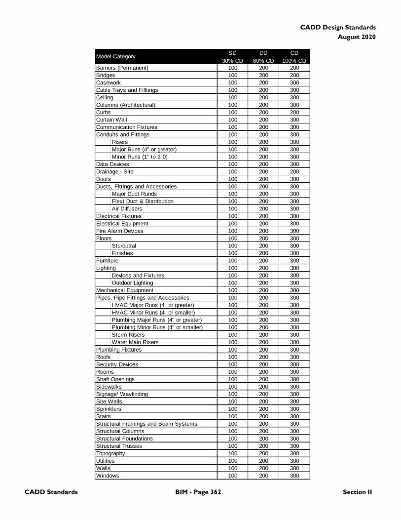
CADD Design Standards
August 2020
CADD Standards BIM - Page 362 Section II
Model CategorySD
30% CD
DD
60% CD
CD
100% CD
Barriers (Permanent) 100 200 200
Bridges 100 200 200
Casework 100 200 300
Cable Trays and Filltings 100 200 300
Ceiling 100 200 300
Columns (Architectural) 100 200 300
Curbs 100 200 200
Curtain Wall 100 200 300
Communication Fixtures 100 200 300
Conduits and Fittings 100 200 300
Risers 100 200 300
Major Runs (4" or greater) 100 200 300
Minor Runs (1" to 2"0) 100 200 300
Data Devices 100 200 300
Drainage - Site 100 200 200
Doors 100 200 300
Ducts, Fittings and Accessories 100 200 300
Major Duct Runds 100 200 300
Flext Duct & Distribution 100 200 300
Air Diffusers 100 200 300
Electrical Fixtures 100 200 300
Electrical Equipment 100 200 300
Fire Alarm Devices 100 200 300
Floors 100 200 300
Sturcutral 100 200 300
Finishes 100 200 300
Furniture 100 200 300
Lighting 100 200 300
Devices and Fixtures 100 200 300
Outdoor Lighting 100 200 300
Mechanical Equipment 100 200 300
Pipes, Pipe Fittings and Accessories 100 200 300
HVAC Major Runs (4" or greater) 100 200 300
HVAC Minor Runs (4" or smaller) 100 200 300
Plumbing Major Runs (4" or greater) 100 200 300
Plumbing Minor Runs (4" or smaller) 100 200 300
Storm Risers 100 200 300
Water Main Risers 100 200 300
Plumbing Fixtures 100 200 300
Roofs 100 200 300
Security Devices 100 200 300
Rooms 100 200 300
Shaft Openings 100 200 300
Sidewalks 100 200 300
Signage/ Wayfinding 100 200 300
Site Walls 100 200 300
Sprinklers 100 200 300
Stairs 100 200 300
Structural Framings and Beam Systems 100 200 300
Structural Columns 100 200 300
Structural Foundations 100 200 300
Structural Trusses 100 200 300
Topography 100 200 300
Utilities 100 200 300
Walls 100 200 300
Windows 100 200 300
CADD Design Standards
August 2020
CADD Standards BIM - Page 363 Section II
8 COORDINATE SYSTEMS
8.1 Authority Survey Control Document: At the start
of each project MWAA will transmit to the AE the current
Authority Survey Control Document and .prj files to
assist in defining the Revit Project Base Point and
Survey Pont to ensure seamless usage with GIS and
future BIM projects.
8.2 MWAA Geospatial Coordinate System:
• American Datum of 1983 (NAD83) State Plane
Virginia North Zone Survey Feet.
• Vertical datum—elevations for Airport control
documentation are based the North American
Vertical Datum of 1988 (NAVD 88).
The AE shall have the option to use a “True North”
setting for specific sheets in the design process or
determine a “Project North” for the works.
9 LINKING FILES
9.1 Linked Files in CAD should employ a consistent
coordinate system as the BIM system. Linked BIM
models should employ Shared Coordinates within Revit
so that proper horizontal and vertical alignment is
achieved. Within Revit, create a unique workset for
each linked file so that the visibility properties can be
easily controlled across views.
10 PROJECT DELIVERABLES
10.1 AE to provide BIM model in Revit Format as final
deliverable to MWAA as part of the 100% deliverable in
parallel with the contractual deliverables.
10.2 Prime Contractor, encompassing GC/ Design-
builder/ CMaR will be responsible for the record model
deliverable to MWAA. The Prime Contractor shall
update the BIM model throughout the construction
process. Changes made to the design during
construction shall be incorporated into the model under
the control of the GC/ Design-builder/ CMaR. Note that
the Prime Contractor may retain the AE separately from
the base MWAA contract to periodically update that BIM
model. At the end of the construction phase, the Prime
Contractor’s BIM model shall be transmitted to MWAA.
10.3 Specific requirements for model delivery and
methodology will be written in the SOW or in Division One
of the project manual.
11 BIM STANDARDS REVIEW
11.1 There is currently no formal process for MWAA to
review BIM development and to audit AE models. AE
shall submit models at 60%, 90%, and 100% during the
design phase for MWAA Record as part of project
deliverables and in accordance with the CAD Manual.
12 MWAA BIM SUPPORT FILES AND LIBRARIES
There are currently no MWAA BIM templates or
Libraries for use by AE team.
13 PROJECT FOLDER STRUCTURE
Not Used in this version
14 MWAA REVIT TEMPLATES
Not Used in this version
15 QUALITY CONTROL/ CLASH DETECTION
15.1 Clash Detection: System detects interferences
between disciplines within the model by indicating hard
and soft collisions of elements. BIM Model Managers
shall perform clash detection using Autodesk Navisworks.
The reporting of the clashes at each performance of
Navisworks shall be documented in meeting notes and an
in trackable PDF format which will be transmitted to
MWAA. AE to provide statement within the Design
Report at 30%, 60%, and 90% which documents the
results of the clash detection exercise. AE to provide a
project template for Colorization per discipline and
classification for depicting the Navisworks output.
15.2 Milestone Submissions: Discipline BIM Project
CADD Design Standards
August 2020
CADD Standards BIM - Page 364 Section II
leads shall review components of the model to ensure
compliance with the overall standards and MWAA
protocols
15.3 Submittal Reviews: BIM Model Managers to
provide final oversight of the accuracy, compliance, and
completeness of the model to the appropriate LOD at
each submission.
16 MWAA STANDARD TITLE SHEETS &
CONTRACT BORDERS
16.1 Refer to CAD Standards for creation of MWAA
Standard Titleblocks and Contract Borders. There are
currently no BIM Families within the MWAA Library, and
it is the sole responsibility of the AE to create BIM.
17 DISCLAIMER
17.1 AE shall provide a signed disclaimer using AIA
standard format to be provided by MWAA, to release
BIM Models to MWAA for construction purpose. In order
for General Contractor / D-B to use the AE model for
pre-construction and construction, General Contractor /
D-B is required to sign a separate disclaimer to release
MWAA and AE from any responsibilities as related to
accuracy and completeness of the BIM Models and will
hold MWAA harmless.
CADD - Page 365 List of Exhibits
CADD Design Standards
August 2020
LIST OF EXHIBITS
SECTION I: CADD Standards .............................................................................................................................................. 13
CHAPTER 2 General Standards ........................................................................................................................................... 16
Exhibit I-2-1 IAD Project Grid ............................................................................................................................. 19
Exhibit I-2-2 DCA project grid ............................................................................................................................. 20
CHAPTER 3 Drawing File Information ................................................................................................................................. 34
Exhibit I-3-1 Model File Naming Convention ...................................................................................................... 35
Exhibit I-3-2 Sheet File Naming Convention ....................................................................................................... 36
Exhibit I-3-3 Addendum File Naming Convention ............................................................................................... 37
Exhibit I-3-4 Authority Standard Drawing Sheet Titleblock For IAD ................................................................... 38
Exhibit I-3-5 Authority Standard Cover Sheet For IAD ....................................................................................... 39
Exhibit I-3-6 Authority Enlarged Plan Sheet For IAD .......................................................................................... 40
Exhibit I-3-7 Authority Standard Drawing Sheet Titleblock For DCA .................................................................. 41
Exhibit I-3-8 Authority Standard Cover Sheet For DCA ...................................................................................... 42
Exhibit I-3-9 Authority Standard Addenda or Sketches Sheet ............................................................................ 43
SECTION II: GIS .................................................................................................................................................................. 351
CHAPTER 1 Geographic Information Systems (GIS)Standards and Submittal Requirements.................................... 351
Exhibit II-1-1 Simple Geometry Types – Using Vertices to Accurately Portray Line or Polygon Shape ............ 354
Exhibit II-1-2 Snapping End Vertices for Adjacent Line Features ...................................................................... 354
Exhibit II-1-3 Polygon Closure via Collocated End Vertices .............................................................................. 355
Exhibit II-1-4 Shared Vertices along Shared Polygon Edges ............................................................................ 355
Exhibit II-1-5 Overlapping and Intersecting Polygons ........................................................................................ 355
Exhibit II-1-6 Snapping Line Endpoints to Cell/Block Insertion Points ............................................................... 356
CADD - Page 366 List of Exhibits
CADD Design Standards
August 2020
(This Page Blank)
CADD - Page 367 Index
CADD Design Standards
August 2020
INDEX
A
A/E (Architect/Engineer), GIS standards and submittal requirements for, 353
abbreviations for references and support files, 350 access
baggage handling system, 304, 305, 306, 307 addenda sketches
Addenda Sheet, 45, 365 naming conventions, 36
AED (automated external defibrillator), 322 aerial survey
survey and mapping plan, 66, 67, 68, 69, 70, 71, 72, 73, 74, 75, 76, 77, 78, 79, 80
X-sections, 110, 111, 112, 113, 114, 115, 116, 117, 118, 119, 120, 121
airfield lighting plan, 102, 103, 294, 295 airfield traffic areas, 79, 177 airport grid file, Design Origin of, 20 alarm system, special systems plan, 287 alignments
airfield plan, 174 eco-restoration plan, 146 flood control plan, 160 grading plan, 143, 174 HTCW utilities plan, 71, 100 hydrographic survey and mapping plan, 85, 153 navigation dredging plan, 153 profiles
civil drawings, 184 survey/mapping, 104
shore bankline, 149 site plan, 132 survey and mapping plan, 66 transportation site plan, 170 utilities plan, 95, 178
annotation levels/layers model files, 30 sheet files, 33
anti-freeze, 270 aprons
profiles civil drawings, 184
aqueous film forming foam system, 250 architectural drawings
area calculations/occupancy plan, 234 demolition plan, 228 details, 237 elevations, 235 equipment plan, 233 floor plan, 243 naming conventions, 54 numbering and organization of, 48 reflected ceiling plan, 231 roof plan, 232 sections, 236
area calculations, 234 arrows on drawings, north, orientation of, 27 audio paging, 315 aviation information systems
demolition plan, 318 drawings, numbering and organization of, 50 plan, 319 sheet level/layer assignments, 345
B
baggage handling system demolition plan, 303 drawings, numbering and organization of, 49 plan, 304 sheet level/layer assignments, 342
Baggage Information Displays (BIDS), level/layer assignments/model files, 316
beams structural buildings, 208, 212 structural civil, 221, 224
bell system, 287 Bentley MicroStation, 350 BIDS (Baggage Information Displays), level/layer
assignments/model files, 315, 316 border sheets, 31, 58, 59 boring log, 126 borings
hydrographic survey and mapping plan, 85 survey and mapping plan, 66
borrow areas flood control plan, 160 grading plan, 143 hydrographic survey and mapping plan, 81 navigation dredging plan, 153 shore bankline, 149 site plan, 132 survey and mapping plan, 68
bracing structural buildings, 208 structural civil, 221
bridges decks, 219 flood control plan, 160 navigation dredging plan, 153 profiles
civil drawings, 184 survey/mapping, 105
site plan, 133 substructure, 216 superstructure, 221 survey and mapping plan, 68 X-sections, civil drawings, 191
brine system, 270
C
cable system electrical power plan, 285 electrical special systems plan, 287 telephone/data plan, 299
cable television (CATV) systems electrical special systems plan, 287 public information systems plan, 316
CADD Standards, 15
CADD - Page 368 Index
CADD Design Standards
August 2020
carpet/carpet tile, 243 cathodic protection system, 92, 291 CATV. See cable television (CATV) systems CCTV (closed-circuit television) systems, electrical special
systems plan, 287 ceilings, reflected ceiling plan, 231 central dictation system, 288 chemical treatment system, 264 clock system, 288 closed-circuit television (CCTV) systems, electrical special
systems plan, 287 CO2 sprinkler system, 250 compressed air, 270 condenser water system, 264 Construction Specifications Institute, Uniform Drawing System,
348 control diagrams, mechanical, 263, 264, 270, 273, 275, 276,
278, 279, 280, 281, 339 control panels
baggage handling plan, 304 fire protection, 248
control points hydrographic survey and mapping plan, 83 survey and mapping plan, 69 X-sections, survey/mapping, 112
controls baggage handling plan, 304 HVAC plan, 266 hydraulic, 271
conveyance (elevators, escalators, and moving walks), 322 conveyors, baggage handling, 304 coordinate system, GIS, 353 Cover Sheet Format
assignment table, 59 DCA, 44 drawing files, 36 IAD, 41
CUSS (common use self service) kiosks, 319
D
data exchange, 33 defibrillators, automated external (AED), 322 demolition levels/layers, 31 Design Manual
applicability of, 3 organization of, 3 revisions to, 5
design origin of airport grid file, 20 dimension terminators, 30 discipline designators, 30 disposal areas, hazardous waste, 62 documentation on drawing files, 33 documents, compliance with, 4 doors in floor plan, 229 drainage, piping, 260 drawing files
documentation on, 33 naming conventions, 36 organization of, 47 setup of, 19 text height, 26
drawing output, 32 dredging plan
civil site plan, 134 flood control plan, 162 navigation, 155 shore bankline, 149
dual temperature system, 265 dust and fume collection systems, 265
E
eco-restoration plan, 131, 132, 143, 146, 149, 153, 160, 170, 173, 174, 178, 184, 190, 191, 198, 330
egress requirements, 248 electronic layout files, 350 elevations
architectural, 235 civil, 141, 190 flood control plan, 168 interiors, 245 mechanical, 278 shore bankline, 152 structural buildings, 213 structural civil, 225
elevators, electronic monitoring systems, 322, 323 Energy Monitoring Control Systems (EMCS), equipment, 288 energy recovery system, 268 equipment pads, 205 equipment plan, 233 escalators, 322, 323 exhaust system, HVAC plan, 265 existing communication system plan, 94 existing electrical utilities plan, 73, 88, 93, 107, 115 existing hydrographic survey and mapping plan, 66, 81, 95,
100, 104, 110 exterior communications systems plan, 293
F
FAA (Federal Aviation Administration), airports GIS database dictionary, 354
fabrications structural buildings, 206, 209 structural civil, 217, 220, 222
fasteners and connections structural buildings, 205, 208 structural civil, 217, 219, 222
Federal Aviation Administration (FAA), airports GIS database dictionary, 354
FIDS (Flight Information Displays), level/layer assignments/model files, 316
file accuracy (units), 19 filled font, 25, 26 fire ratings, 249 fire suppression plan, 250 Flight Information Displays (FIDS), level/layer
assignments/model files, 316 flood control plan, 133, 153, 160, 170 floor patterns, 229 floor plans, 229 fonts, 25 framing plan, 204, 205, 208, 211, 212, 214, 215, 332
CADD - Page 369 Index
CADD Design Standards
August 2020
G
gas piping, 258, 259, 261, 262, 338 Geographic Information Systems (GIS), 353 geometry types, complex vs. simple, 356 geothermal heat pump system, 66, 81, 86, 92, 94, 95, 100,
102, 104, 110, 265, 273, 328 GIS (Geographic Information Systems), 353 GIS Database Dictionary, 354 global origin, 20 glycol system, 265, 271 grading plan, 131, 132, 143, 146, 149, 153, 160, 170, 173, 174,
178, 184, 190, 191, 198, 330 graphics system drawings, numbering and organization of, 50 grid system, 20 grounding system plan, 290
H
habitats/landforms eco-restoration plan, 146 survey and mapping plan, 70
halon system, 250 hazardous materials
demolition plan, 61 details, 65 pollution prevention plan, 62 sections, 64
heat pump system, geothermal, 282, 283, 285, 287, 290, 291, 293, 294, 296, 297, 340
heliports airfield plan, 175 profiles, civil drawings, 186 X-sections, civil drawings, 193
hot water systems, heating, 267 HVAC (heating, ventilating, and air conditioning) system plan,
263, 264, 270, 273, 275, 276, 278, 279, 280, 281, 339 hydraulic control systems, 271 hydrographic survey and mapping plan, existing, 66, 81, 95,
100, 104, 110
I
IAD. See Washington Dulles International Airport iMUSE (intelligent Multiple User System Equipment) system,
319 inch-pound text sizes and line type scales, 26, 27 industrial waste water
flood control plan, 164 navigation dredging plan, 156 piping, mechanical, 270 profiles
civil drawings, 186 survey/mapping, 107
property boundary, 87 site plan, 136 survey and mapping plan,, 71 utilities plan, 97, 180 X-sections
civil drawings, 193 survey and mapping drawings, 114
inert gas, 250 insertion points, model files for GIS integration, 358 insulating (transformer) oil system, 271
intelligent Multiple User System Equipment (iMUSE) system, 319
intercom/public address system, 288 interiors
demolition plan, 238 details, 246 elevations, 245 floor patterns, 243 furniture plan, 239 furniture workstation plan, 241 signage placement plan, 242
international feet versus survey feet, 19 irrigation
civil drawings, elevations, 190 details, 198 eco-restoration plan, 147 hydrographic survey and mapping plan, 83 profiles
civil drawings, 186 survey/mapping, 71
site plan, 136 utilities plan, 97, 180 X-sections
civil drawings, 193 survey and mapping drawings, 114
J
jacks, 299 joint layout plan
civil drawings, 173 geotechnical drawings, 127
joints structural buildings, 206, 209, 212 structural civil, 219, 222, 224 survey and mapping plan, 72
joists, structural buildings, 206, 209 junction boxes, telephone/data plan, 300
K
key plan, 61, 62, 64, 65, 327 kiosks, common use self service, 318, 319, 345
L
laboratory gas piping, 259 landscape
demolition plan, 199 details, 203 drawings, naming conventions, 54 irrigation plan, 202 landscape plan, 201 sheet level/layer assignments, 331
leader lines, 29 levees
navigation dredging plan, 156 profiles, civil drawings, 186 site plan, 136 survey and mapping plan, 72 X-sections
civil drawings, 193 survey and mapping drawings, 114
CADD - Page 370 Index
CADD Design Standards
August 2020
life safety plan, 248 lubrication oil, 271
M
machine design, 276 makeup air system, 267 Master Clock system, 316 master units, 19 material handling, 275 mechanical drawings
control diagrams, 281 demolition plan, 263 details, 280 elevations, 278 HTCW utilities plan, 273 HVAC plan, 269 machine design, 276 material handling, 275 naming conventions, 55 numbering and organization of, 49 sections, 279 sheet level/layer assignments, 339 specialty piping and equipment, 272
media format, 33 medical/dental gas piping, 260 mixed air system, 267 model files
compiling CADD features in, 33 creating GIS features from, 353 description of, 20, 30 for GIS integration, 355 level/layer assignment tables, 56
monitoring stations, hazardous waste, 323 monolithic flooring, 243 monotext font, 25 motor control panels, baggage handling plan, 304 moving walks, 322 Multi-User Flight Information Display System (MUFIDS),
level/layer assignments/model files, 315
N
naming conventions, 53 natural gas
navigation dredging plan, 156 piping, 271 profiles
civil drawings, 187 survey/mapping, 107
property boundary, 97 site plan, 137 survey and mapping plan, 72 utilities plan, 97, 180 X-sections
civil drawings, 194 survey and mapping drawings, 114
navigation dredging plan, 154 north arrow, orientation of, 27 nurse call/paging system, 288
O
obstructions airfield plan, 175 hydrographic survey and mapping plan,, 83 X-sections, survey/mapping, 114
occupancy plan, 234 oil, lubrication, 271 one-line diagrams, 297, See riser diagrams orientation of drawings, 27 origin of drawing file, 20 outline font, 26 overrun areas
airfield plan, 175 profiles
civil drawings, 187 survey/mapping, 107
X-sections civil drawings, 194 survey and mapping drawings, 115
P
PA system, 289 pads (arm/disarm/calibration) airfield plan, 175
profiles civil drawings, 187 survey/mapping, 107
X-sections civil drawings, 194 survey and mapping drawings, 115
pads, equipment, structural buildings foundation plan,, 205 paging system, 288 project grid
DCA, 22 IAD, 21
Project Identifier, 46 project organization, 15 property boundary survey and mapping plan, 88 proportional font, 26
Q
Quality Check (QC) CADD checklist, 36
R
raw water piping, 272 reflected ceiling plan, 231 refrigeration system, 268 relief air system, 268 relocation, baggage handling plan, 305 resilient flooring, 243 revisions to Design Manual, 6 riser diagrams, 297 Ronald Reagan Washington National Airport
Cover Sheet, format for, 44 project grid, 22 Title Block, format for, 43
roof plan, 232 runways
profiles civil drawings, 188
CADD - Page 371 Index
CADD Design Standards
August 2020
survey/mapping, 108 survey and mapping plan, 75 X-sections
civil drawings, 195 survey and mapping drawings, 117
S
safety features, structural civil, 220, 223 sample points, pollution prevention plan, 63 sanitary drainage piping, 260 SCADA (Supervisory Control & Date Acquisition), level/layer
assignments/model files, 322 screening of graphics, 25 smoke/pressurization control, 249 software, requirements for, 15 sound system, 289 sprinkler system, 250 symbols, CADD, 348
T
target systems, 19 telecommunications system drawings, naming conventions, 55 telephone/data plan, 299 temporary work, baggage handling plan, 303 terminators, 29 terminology, interchangeable, between AutoCAD and
MicroStation, 19 text height, on drawings, 26 text styles, 25 tile flooring, 244 topography
airfield plan, 176 eco-restoration plan, 147 flood control plan, 167 grading plan, 144 hydrographic survey and mapping plan, 84 joint layout plan, 173 navigation dredging plan, 158 shore bankline, 151 transportation site plan, 172 utilities plan, 183 X-sections, survey/mapping, 119
transfer air system, 269 Transportation Security Administration (TSA), baggage
handling plan, 305 transportation site plan, 172 trusses
structural buildings, 210 structural civil, 223
TV antenna system, 289
U
underground ductbanks
communication system plan, 94, 293 electrical utilities plan, 93 profiles, survey/mapping,, 106 property boundary, 87 survey and mapping plan, 70 X-sections, survey/mapping, 112
utilities plan civil drawings, 178 domestic water, 178 electrical, 291 HTCW, 100 industrial waste water, 180 irrigation, 180 liquid fuel, 179 natural gas, 180 sanitary sewer, 181 storm sewer, 182 survey/mapping, 95
V
visual paging, 315
W
walkways, moving, 322 walls
in floor plan, 230 structural buildings, 207, 210, 212 structural civil, 218
Washington Dulles International Airport Cover Sheet, format for, 41 Plan Sheet for, 42 project grid, 22 Sheet Title Block, format for, 40
water supply and distribution, fire suppression plan, 251 water systems
industrial waste water, 71 temperature/chilled water (HTCW) system, 87
waterway specialties, 218 wetlands
eco-restoration plan, 148 X-sections, survey and mapping plan, 121 X-sections, survey/mapping, 79
width of lines in graphics, 29 windows in floor plan, 230 wireless & radio system drawings, numbering and organization
of, 50 workstation plan, 241
X
X-sections civil drawings, 191 existing, survey/mapping, 121

END OF DOCUMENT