CADD Standards 022807 - San Antonio Water System · consultant electronic and paper deliverables...
46
SAN ANTONIO WATER SYSTEM Infrastructure Planning – GIS / Mapping Division CADD STANDARDS
-
Upload
truongdiep -
Category
Documents
-
view
215 -
download
0
Transcript of CADD Standards 022807 - San Antonio Water System · consultant electronic and paper deliverables...

SAN ANTONIO WATER SYSTEM
Infrastructure Planning – GIS / Mapping Division
CADD STANDARDS

i
I N F R A S T R U C T U R E P L A N N I N G
CADD STANDARDS
SAN ANTONIO WATER SYSTEM 2800 U.S. Hwy. 281 North
San Antonio, TX 78212 www.SAWS.org
Last Revised Thursday, May 17, 2007 Document1

ii
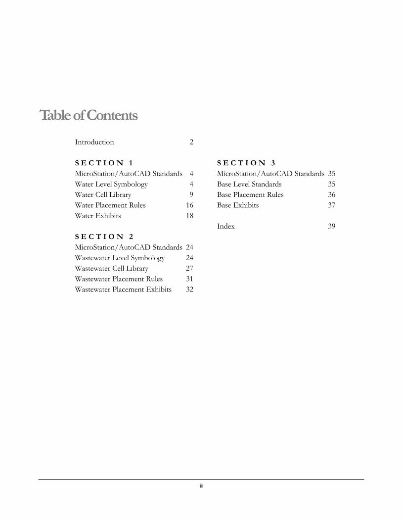
Table of Contents
Introduction 2
S E C T I O N 1 MicroStation/AutoCAD Standards 4 Water Level Symbology 4 Water Cell Library 9 Water Placement Rules 16 Water Exhibits 18
S E C T I O N 2 MicroStation/AutoCAD Standards 24 Wastewater Level Symbology 24 Wastewater Cell Library 27 Wastewater Placement Rules 31 Wastewater Placement Exhibits 32
S E C T I O N 3 MicroStation/AutoCAD Standards 35 Base Level Standards 35 Base Placement Rules 36 Base Exhibits 37 Index 39
1
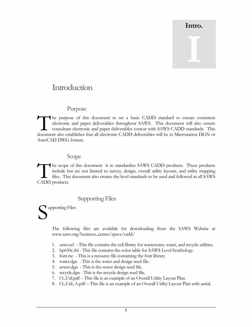
Introduction
Purpose he purpose of this document to set a basic CADD standard to ensure consistent electronic and paper deliverables throughout SAWS. This document will also ensure consultant electronic and paper deliverables concur with SAWS CADD standards. This
document also establishes that all electronic CADD deliverables will be in Microstation DGN or AutoCAD DWG format.
Scope he scope of this document is to standardize SAWS CADD products. These products include but are not limited to survey, design, overall utility layouts, and utility mapping files. This document also creates the level standards to be used and followed in all SAWS
CADD products.
Supporting Files
upporting Files-
The following files are available for downloading from the SAWS Website at www.saws.org/business_center/specs/cadd/
1. saws.cel - This file contains the cell library for wastewater, water, and recycle utilities. 2. hp650c.tbl - This file contains the color table for SAWS Level Symbology. 3. font.rsc - This is a resource file containing the font library. 4. water.dgn - This is the water and design seed file. 5. sewer.dgn - This is the sewer design seed file. 6. recycle.dgn - This is the recycle design seed file. 7. O_Util.pdf – This file is an example of an Overall Utility Layout Plan. 8. O_Util_A.pdf – This file is an example of an Overall Utility Layout Plan with aerial.
Intro.
I
T
T
S
3
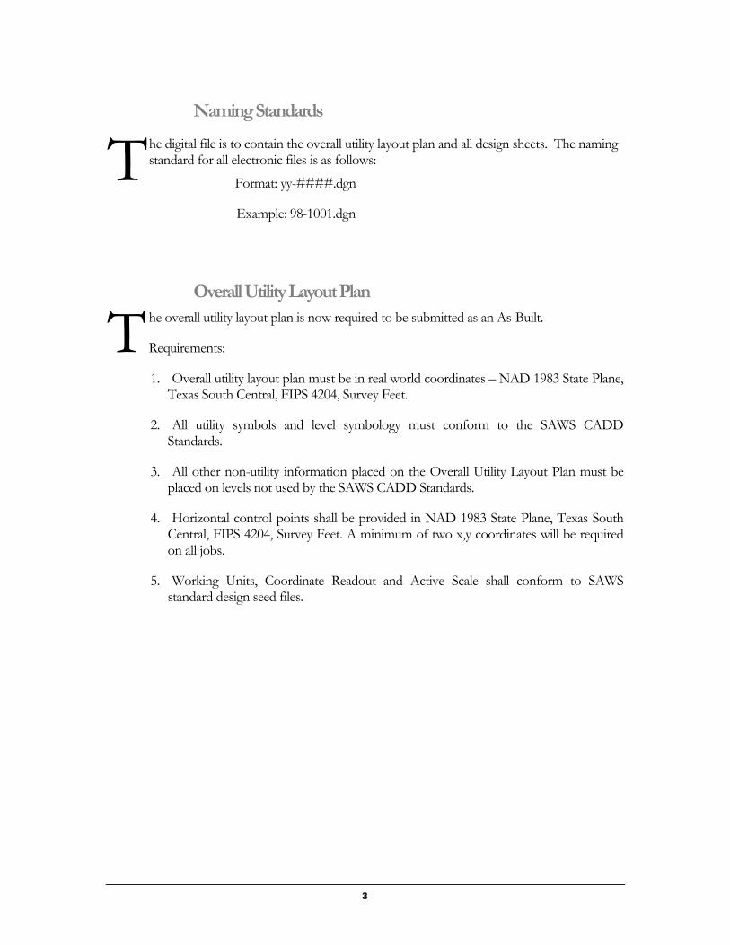
Naming Standards
he digital file is to contain the overall utility layout plan and all design sheets. The naming standard for all electronic files is as follows:
Format: yy-####.dgn
Example: 98-1001.dgn
Overall Utility Layout Plan he overall utility layout plan is now required to be submitted as an As-Built.
Requirements:
1. Overall utility layout plan must be in real world coordinates – NAD 1983 State Plane, Texas South Central, FIPS 4204, Survey Feet.
2. All utility symbols and level symbology must conform to the SAWS CADD Standards.
3. All other non-utility information placed on the Overall Utility Layout Plan must be placed on levels not used by the SAWS CADD Standards.
4. Horizontal control points shall be provided in NAD 1983 State Plane, Texas South Central, FIPS 4204, Survey Feet. A minimum of two x,y coordinates will be required on all jobs.
5. Working Units, Coordinate Readout and Active Scale shall conform to SAWS standard design seed files.
T
T
1
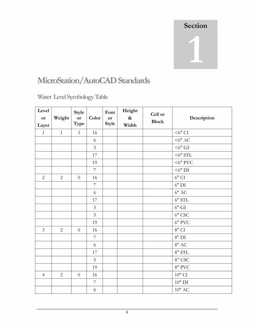
MicroStation/AutoCAD Standards
Water Level Symbology Table
Level
or
Layer
Weight Style
or Type
Color Font
or Style
Height
&
Width
Cell or
Block Description
1 1 3 16 <6" CI 6 <6" AC 3 <6" GI 17 <6" STL 19 <6" PVC 7 <6" DI 2 2 0 16 6" CI 7 6" DI 6 6" AC 17 6" STL 3 6" GI 5 6" CSC 19 6" PVC 3 2 0 16 8" CI 7 8" DI 6 8" AC 17 8" STL 5 8” CSC 19 8" PVC 4 2 0 16 10" CI 7 10" DI 6 10" AC
Section
1
5
Level
or
Layer
Weight Style
or Type
Color Font
or Style
Height
&
Width
Cell or
Block Description
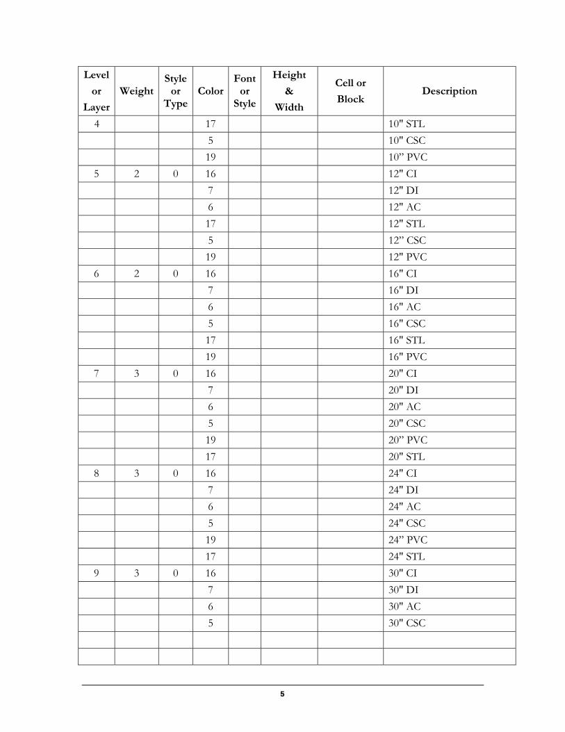
4 17 10" STL 5 10" CSC 19 10” PVC 5 2 0 16 12" CI 7 12" DI 6 12" AC 17 12" STL 5 12” CSC 19 12" PVC 6 2 0 16 16" CI 7 16" DI 6 16" AC 5 16" CSC 17 16" STL 19 16" PVC 7 3 0 16 20" CI 7 20" DI 6 20" AC 5 20" CSC 19 20” PVC 17 20" STL 8 3 0 16 24" CI 7 24" DI 6 24" AC 5 24" CSC 19 24” PVC 17 24" STL 9 3 0 16 30" CI 7 30" DI 6 30" AC 5 30" CSC
1
Level
or
Layer
Weight Style
or Type
Color Font
or Style
Height
&
Width
Cell or
Block Description
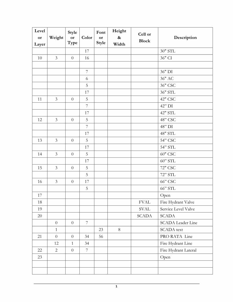
17 30" STL 10 3 0 16 36" CI 7 36" DI 6 36" AC 5 36" CSC 17 36" STL
11 3 0 5 42" CSC 7 42” DI 17 42" STL
12 3 0 5 48” CSC 7 48” DI 17 48" STL
13 3 0 5 54” CSC 17 54” STL
14 3 0 5 60" CSC 17 60” STL
15 3 0 5 72" CSC 5 72” STL
16 3 0 17 66” CSC 5 66” STL
17 Open 18 FVAL Fire Hydrant Valve 19 SVAL Service Level Valve 20 SCADA SCADA 0 0 7 SCADA Leader Line 1 23 8 SCADA text
21 0 0 34 56 PRO RATA Line 12 1 34 Fire Hydrant Line
22 2 0 7 Fire Hydrant Lateral 23 Open
7
Level
or
Layer
Weight Style
or Type
Color Font
or Style
Height
&
Width
Cell or
Block Description
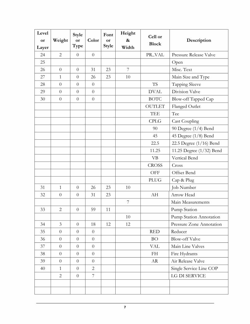
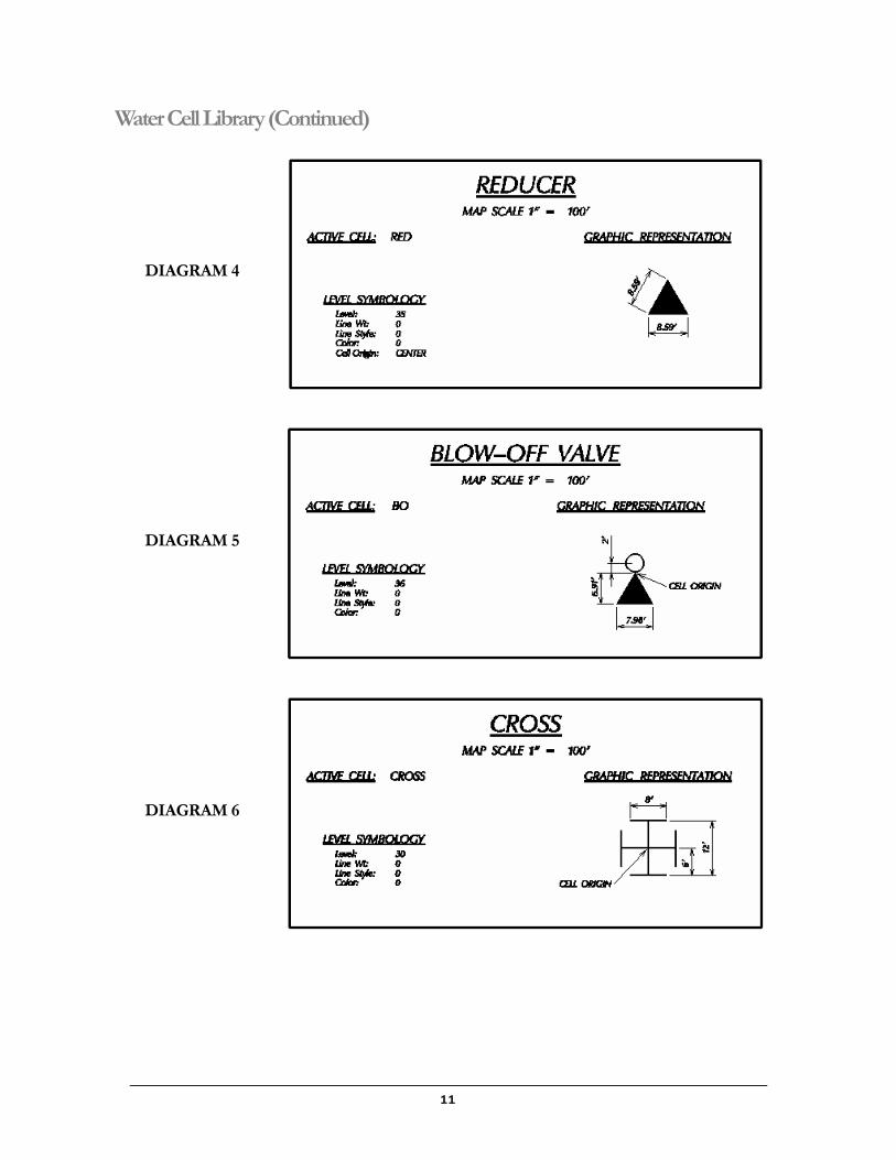
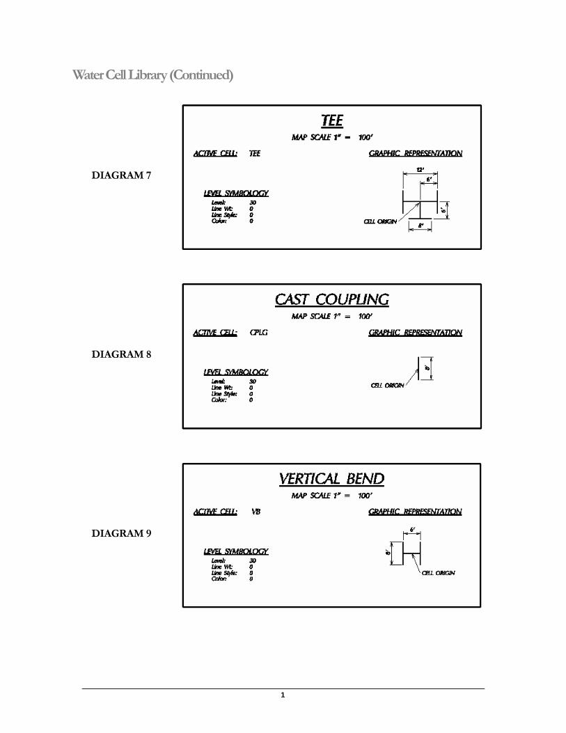
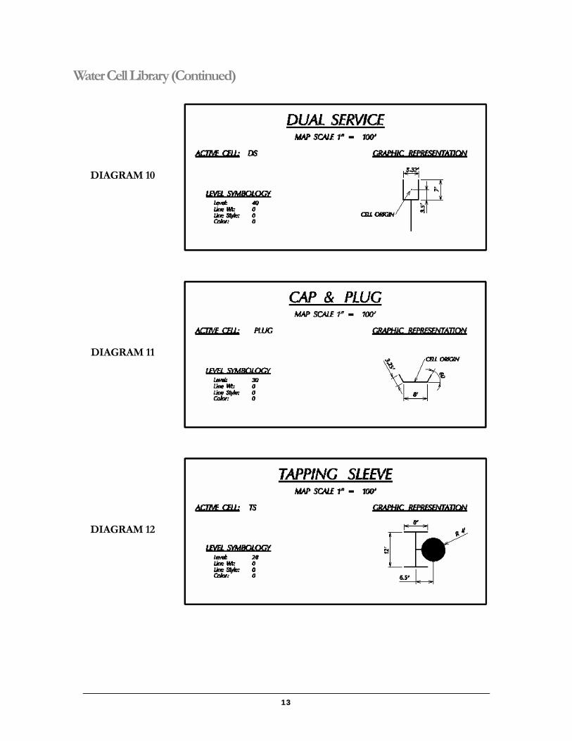
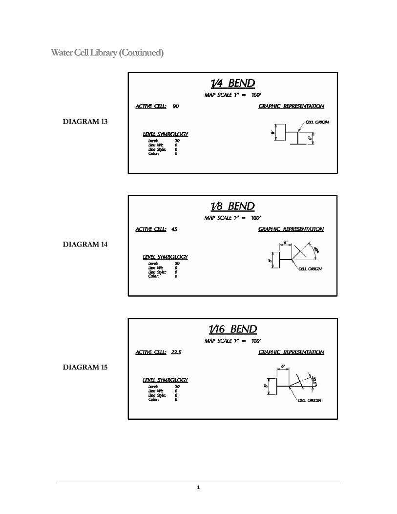
24 2 0 0 PR_VAL Pressure Release Valve 25 Open 26 0 0 31 23 7 Misc. Text 27 1 0 26 23 10 Main Size and Type 28 0 0 0 TS Tapping Sleeve 29 0 0 0 DVAL Division Valve 30 0 0 0 BOTC Blow-off Tapped Cap OUTLET Flanged Outlet TEE Tee CPLG Cast Coupling 90 90 Degree (1/4) Bend 45 45 Degree (1/8) Bend 22.5 22.5 Degree (1/16) Bend 11.25 11.25 Degree (1/32) Bend VB Vertical Bend CROSS Cross OFF Offset Bend PLUG Cap & Plug
31 1 0 26 23 10 Job Number 32 0 0 31 23 AH Arrow Head 7 Main Measurements
33 2 0 59 11 Pump Station 10 Pump Station Annotation
34 3 0 18 12 12 Pressure Zone Annotation 35 0 0 0 RED Reducer 36 0 0 0 BO Blow-off Valve 37 0 0 0 VAL Main Line Valves 38 0 0 0 FH Fire Hydrants 39 0 0 0 AR Air Release Valve 40 1 0 2 Single Service Line COP 2 0 7 LG DI SERVICE
1
Level
or
Layer
Weight Style
or Type
Color Font
or Style
Height
&
Width
Cell or
Block Description
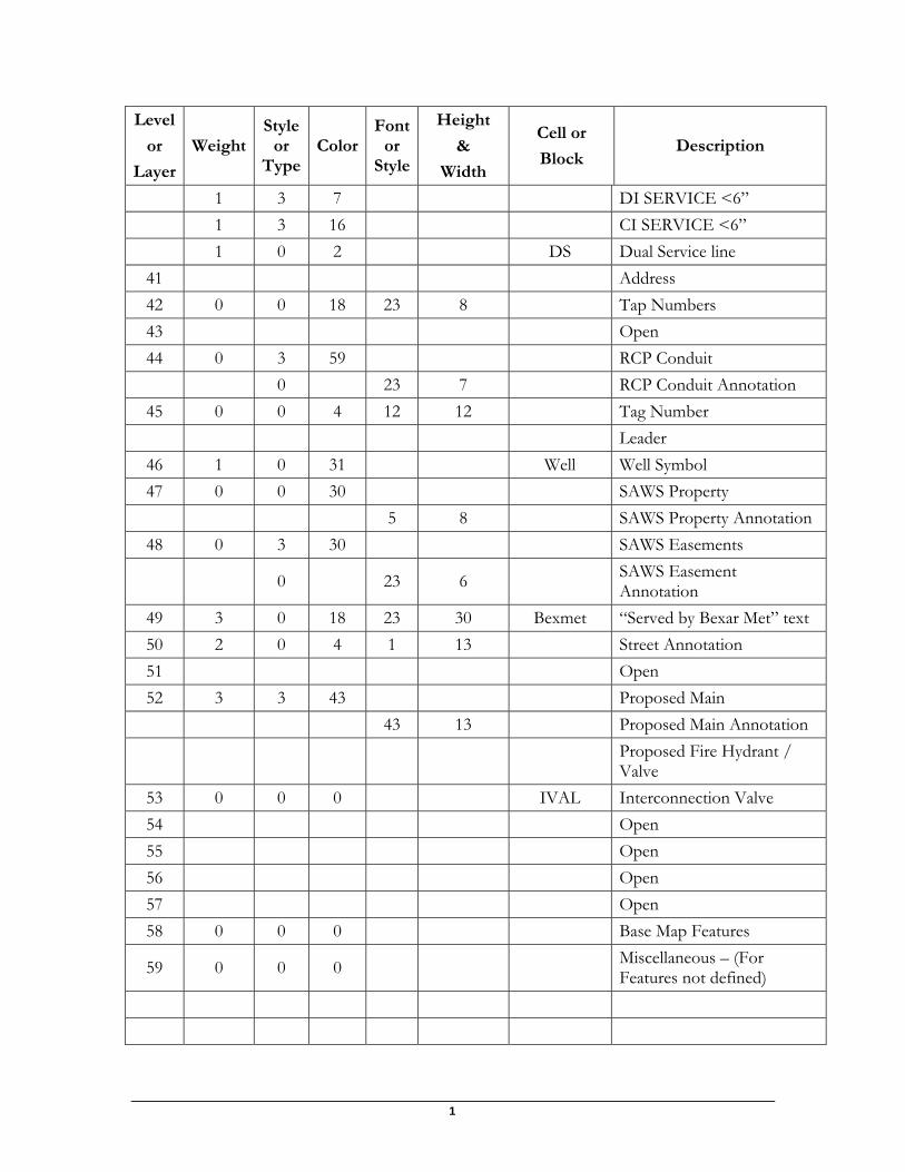
1 3 7 DI SERVICE <6” 1 3 16 CI SERVICE <6” 1 0 2 DS Dual Service line
41 Address 42 0 0 18 23 8 Tap Numbers 43 Open 44 0 3 59 RCP Conduit 0 23 7 RCP Conduit Annotation
45 0 0 4 12 12 Tag Number Leader
46 1 0 31 Well Well Symbol 47 0 0 30 SAWS Property 5 8 SAWS Property Annotation
48 0 3 30 SAWS Easements
0 23 6 SAWS Easement Annotation
49 3 0 18 23 30 Bexmet “Served by Bexar Met” text 50 2 0 4 1 13 Street Annotation 51 Open 52 3 3 43 Proposed Main 43 13 Proposed Main Annotation
Proposed Fire Hydrant / Valve
53 0 0 0 IVAL Interconnection Valve 54 Open 55 Open 56 Open 57 Open 58 0 0 0 Base Map Features
59 0 0 0 Miscellaneous – (For Features not defined)
9
Level
or
Layer
Weight Style
or Type
Color Font
or Style
Height
&
Width
Cell or
Block Description
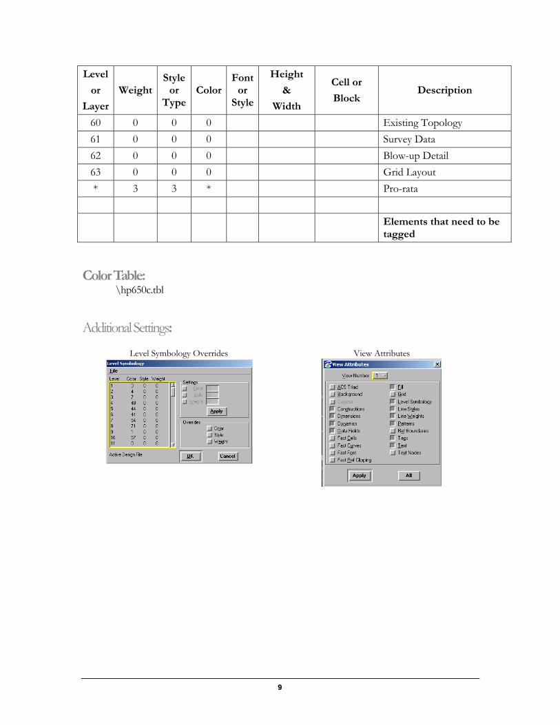
60 0 0 0 Existing Topology 61 0 0 0 Survey Data 62 0 0 0 Blow-up Detail 63 0 0 0 Grid Layout * 3 3 * Pro-rata
Elements that need to be tagged
Color Table: \hp650c.tbl
Additional Settings:
Level Symbology Overrides View Attributes
1
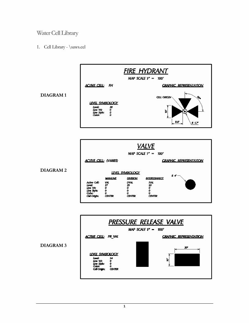
Water Cell Library
1. Cell Library - \saws.cel
DIAGRAM 1
DIAGRAM 2
DIAGRAM 3
11
Water Cell Library (Continued)
DIAGRAM 4
DIAGRAM 5
DIAGRAM 6
1
Water Cell Library (Continued)
DIAGRAM 7
DIAGRAM 8
DIAGRAM 9
13
Water Cell Library (Continued)
DIAGRAM 10
DIAGRAM 11
DIAGRAM 12
1
Water Cell Library (Continued)
DIAGRAM 13
DIAGRAM 14
DIAGRAM 15
15
Water Cell Library (Continued)
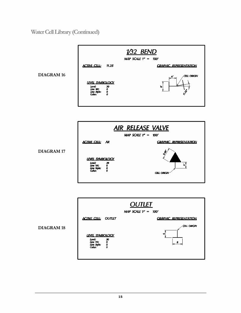
DIAGRAM 16
DIAGRAM 17
DIAGRAM 18
1
Water Cell Library (Continued)
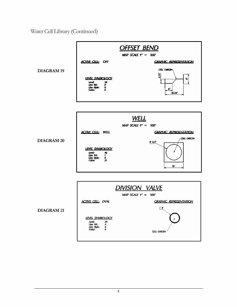
DIAGRAM 19
DIAGRAM 20
DIAGRAM 21
17
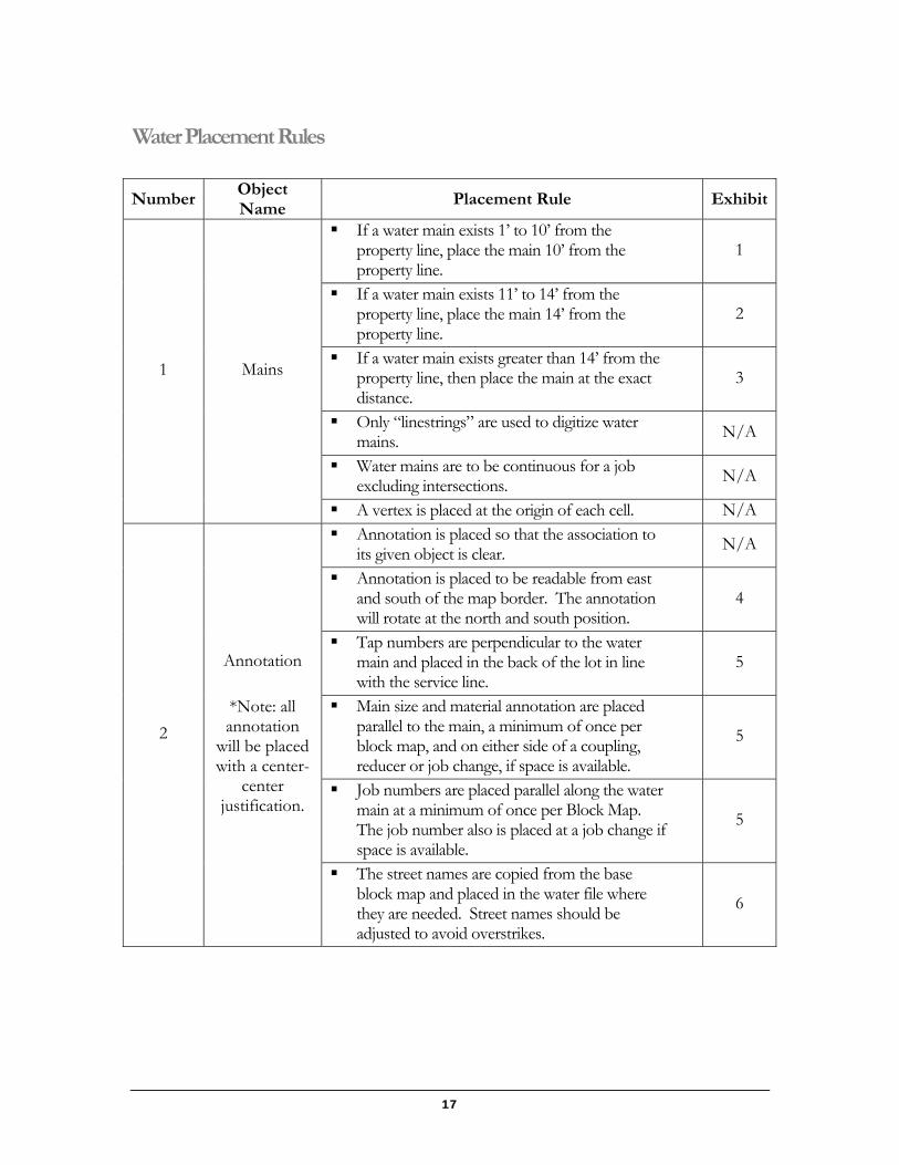
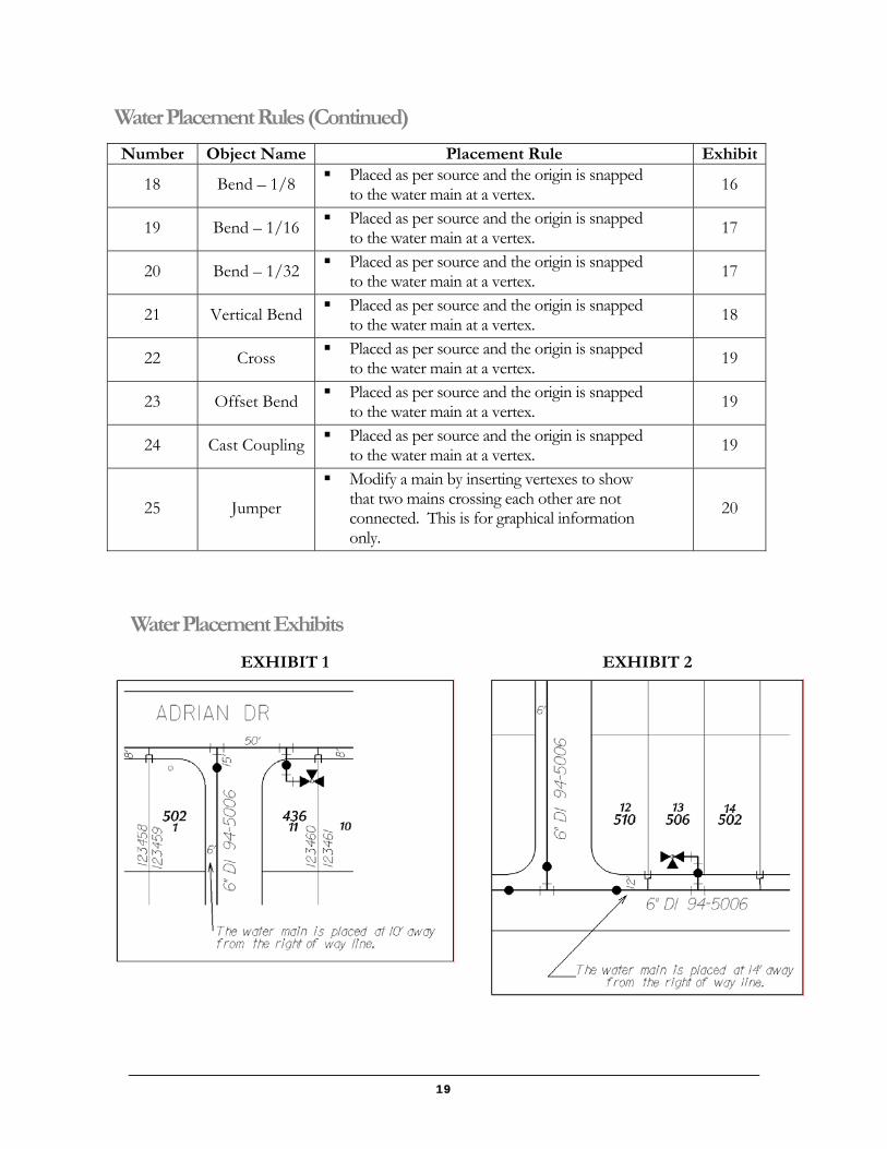
Water Placement Rules
Number Object Name
Placement Rule Exhibit
If a water main exists 1’ to 10’ from the property line, place the main 10’ from the property line.
1
If a water main exists 11’ to 14’ from the property line, place the main 14’ from the property line.
2
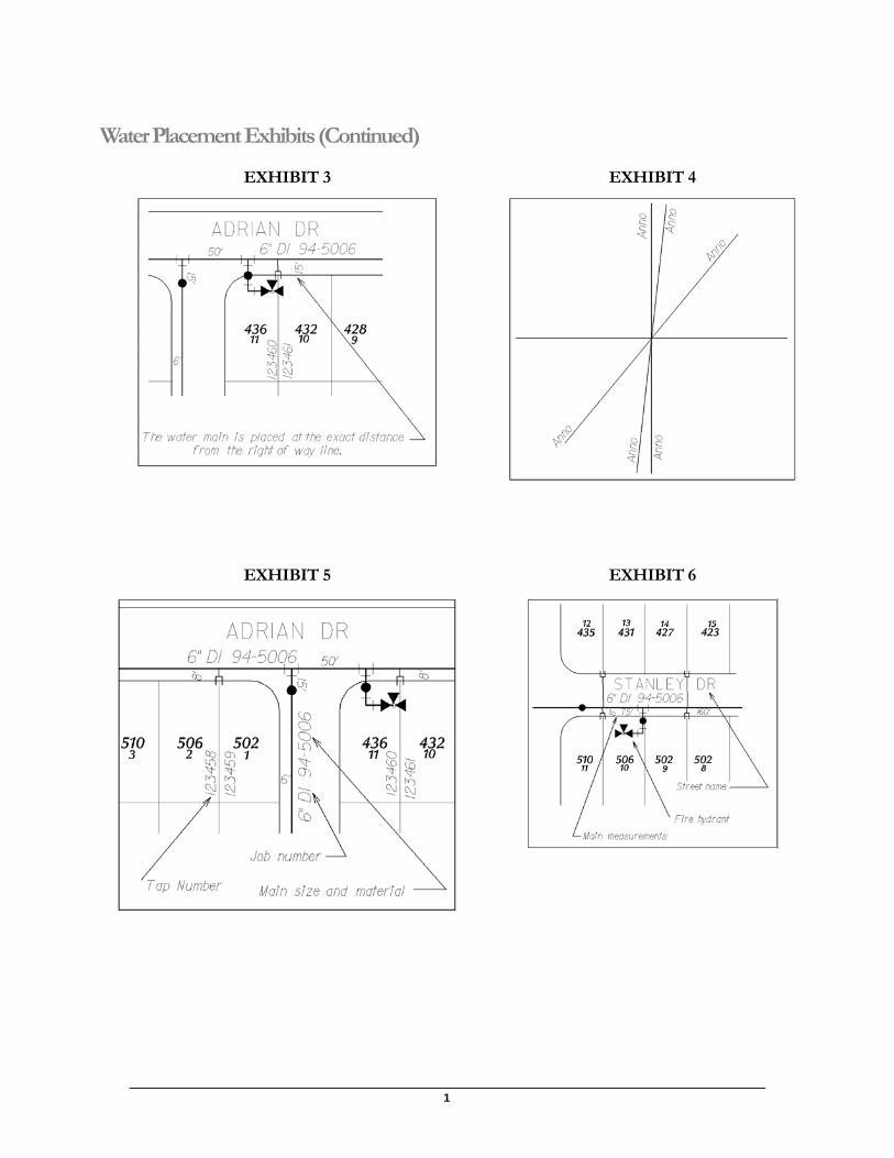
If a water main exists greater than 14’ from the property line, then place the main at the exact distance.
3
Only “linestrings” are used to digitize water mains. N/A
Water mains are to be continuous for a job excluding intersections. N/A
1 Mains
A vertex is placed at the origin of each cell. N/A Annotation is placed so that the association to
its given object is clear. N/A
Annotation is placed to be readable from east and south of the map border. The annotation will rotate at the north and south position.
4
Tap numbers are perpendicular to the water main and placed in the back of the lot in line with the service line.
5
Main size and material annotation are placed parallel to the main, a minimum of once per block map, and on either side of a coupling, reducer or job change, if space is available.
5
Job numbers are placed parallel along the water main at a minimum of once per Block Map. The job number also is placed at a job change if space is available.
5
2
Annotation
*Note: all annotation
will be placed with a center-
center justification.
The street names are copied from the base block map and placed in the water file where they are needed. Street names should be adjusted to avoid overstrikes.
6
1
Water Placement Rules (Continued)
Number Object Name Placement Rule Exhibit Main dimensions are placed between the main
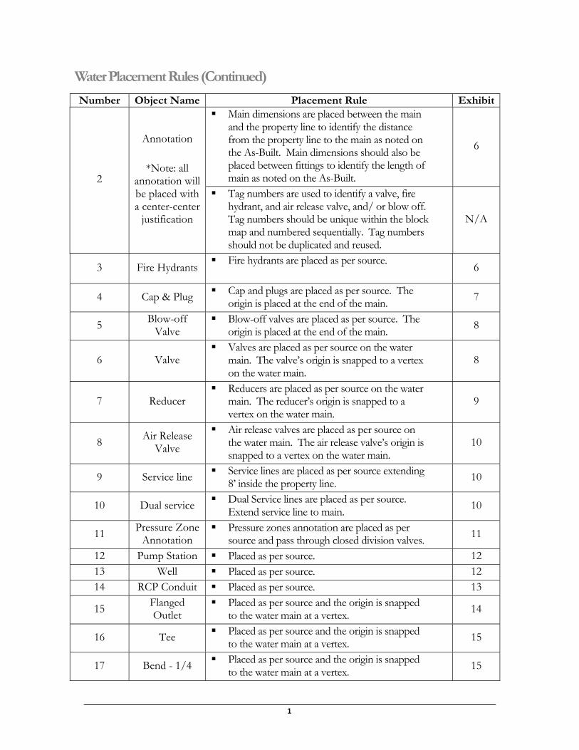
and the property line to identify the distance from the property line to the main as noted on the As-Built. Main dimensions should also be placed between fittings to identify the length of main as noted on the As-Built.
6
2
Annotation
*Note: all annotation will be placed with a center-center
justification
Tag numbers are used to identify a valve, fire hydrant, and air release valve, and/ or blow off. Tag numbers should be unique within the block map and numbered sequentially. Tag numbers should not be duplicated and reused.
N/A
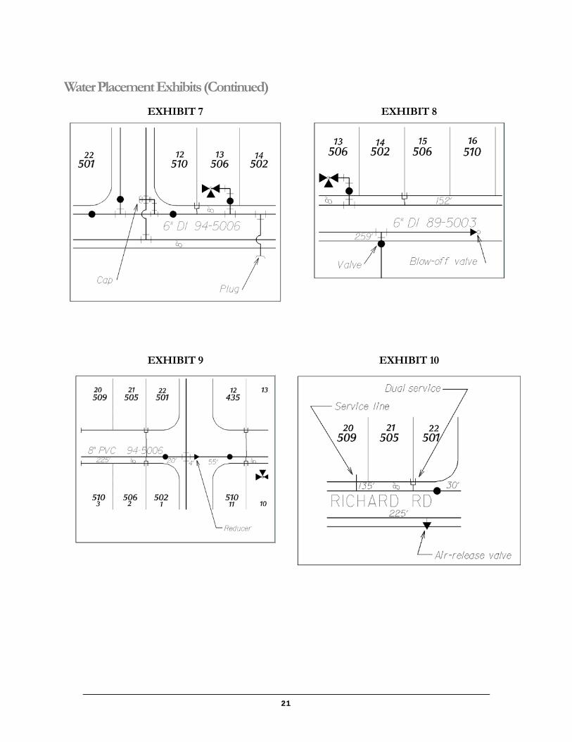
3 Fire Hydrants Fire hydrants are placed as per source.
6
4 Cap & Plug Cap and plugs are placed as per source. The origin is placed at the end of the main. 7
5 Blow-off Valve
Blow-off valves are placed as per source. The origin is placed at the end of the main. 8
6 Valve Valves are placed as per source on the water
main. The valve’s origin is snapped to a vertex on the water main.
8
7 Reducer Reducers are placed as per source on the water
main. The reducer’s origin is snapped to a vertex on the water main.
9
8 Air Release Valve
Air release valves are placed as per source on the water main. The air release valve’s origin is snapped to a vertex on the water main.
10
9 Service line Service lines are placed as per source extending 8’ inside the property line. 10
10 Dual service Dual Service lines are placed as per source. Extend service line to main. 10
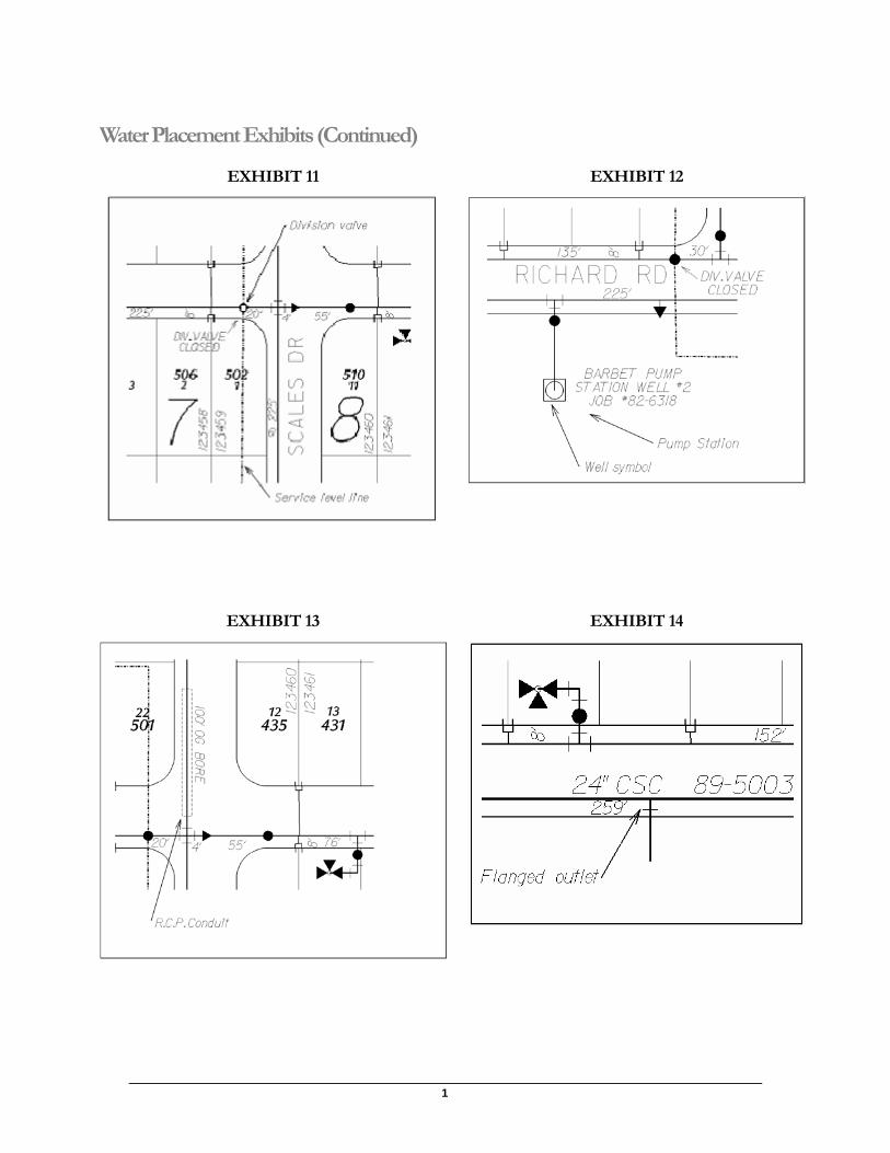
11 Pressure Zone Annotation
Pressure zones annotation are placed as per source and pass through closed division valves. 11
12 Pump Station Placed as per source. 12 13 Well Placed as per source. 12 14 RCP Conduit Placed as per source. 13
15 Flanged Outlet
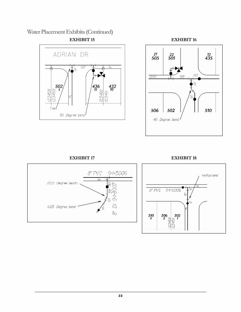
Placed as per source and the origin is snapped to the water main at a vertex. 14
16 Tee Placed as per source and the origin is snapped to the water main at a vertex. 15
17 Bend - 1/4 Placed as per source and the origin is snapped to the water main at a vertex. 15
19
Water Placement Rules (Continued)
Number Object Name Placement Rule Exhibit
18 Bend – 1/8 Placed as per source and the origin is snapped to the water main at a vertex. 16
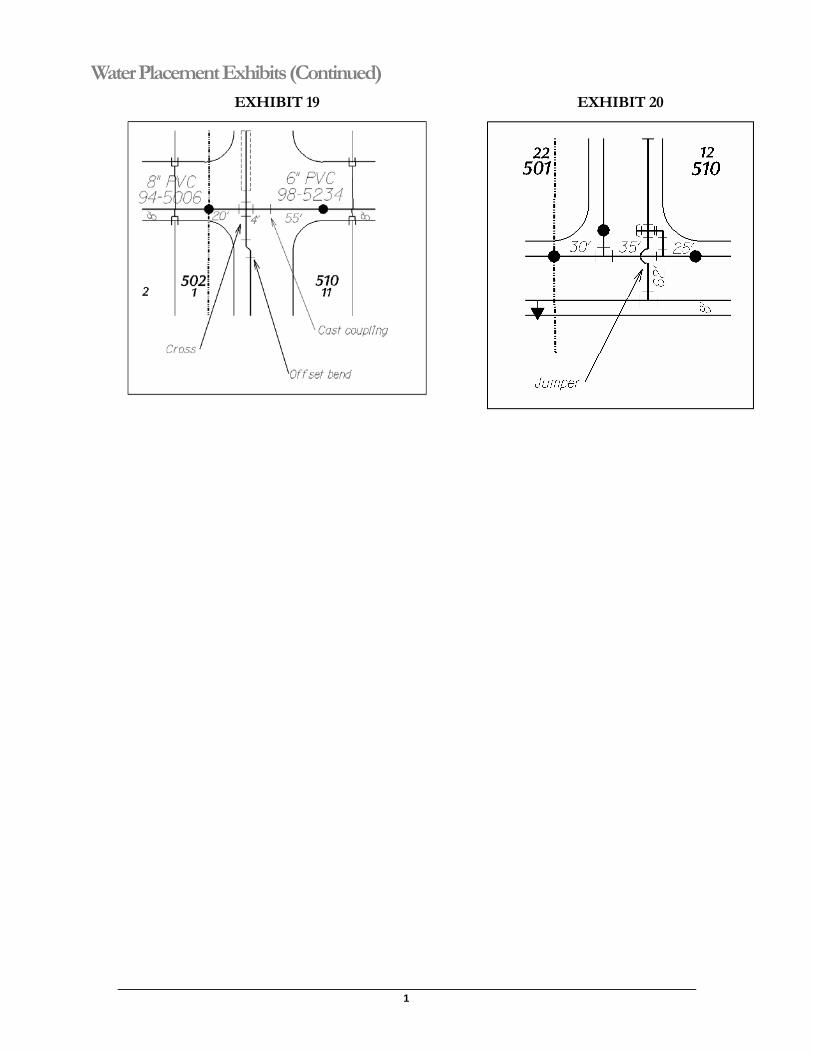
19 Bend – 1/16 Placed as per source and the origin is snapped to the water main at a vertex. 17
20 Bend – 1/32 Placed as per source and the origin is snapped to the water main at a vertex. 17
21 Vertical Bend Placed as per source and the origin is snapped to the water main at a vertex. 18
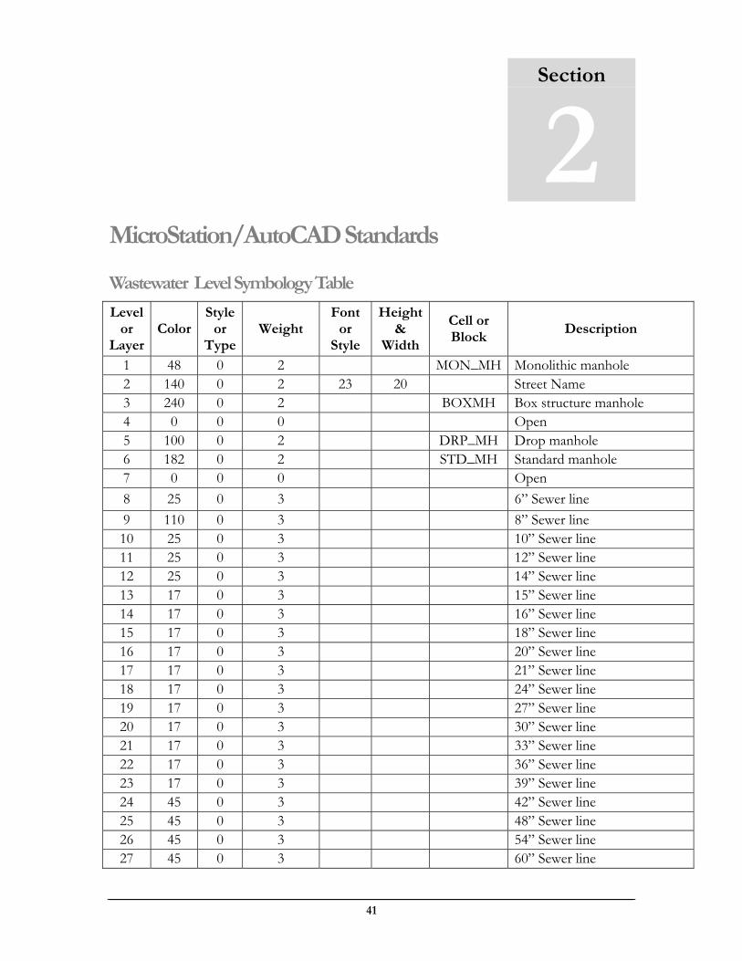
22 Cross Placed as per source and the origin is snapped to the water main at a vertex. 19
23 Offset Bend Placed as per source and the origin is snapped to the water main at a vertex. 19
24 Cast Coupling Placed as per source and the origin is snapped to the water main at a vertex. 19
25 Jumper
Modify a main by inserting vertexes to show that two mains crossing each other are not connected. This is for graphical information only.
20
Water Placement Exhibits
EXHIBIT 1 EXHIBIT 2
1
Water Placement Exhibits (Continued)
EXHIBIT 3 EXHIBIT 4
EXHIBIT 5 EXHIBIT 6
21
Water Placement Exhibits (Continued)
EXHIBIT 7 EXHIBIT 8
EXHIBIT 9 EXHIBIT 10
1
Water Placement Exhibits (Continued)
EXHIBIT 11 EXHIBIT 12
EXHIBIT 13 EXHIBIT 14
23
Water Placement Exhibits (Continued) EXHIBIT 15 EXHIBIT 16
EXHIBIT 17 EXHIBIT 18
1
Water Placement Exhibits (Continued) EXHIBIT 19 EXHIBIT 20
41
MicroStation/AutoCAD Standards
Wastewater Level Symbology Table
Level or
Layer Color
Style or
Type Weight
Font or
Style
Height &
Width
Cell or Block
Description
1 48 0 2 MON_MH Monolithic manhole 2 140 0 2 23 20 Street Name 3 240 0 2 BOXMH Box structure manhole 4 0 0 0 Open 5 100 0 2 DRP_MH Drop manhole 6 182 0 2 STD_MH Standard manhole 7 0 0 0 Open 8 25 0 3 6” Sewer line 9 110 0 3 8” Sewer line 10 25 0 3 10” Sewer line 11 25 0 3 12” Sewer line 12 25 0 3 14” Sewer line 13 17 0 3 15” Sewer line 14 17 0 3 16” Sewer line 15 17 0 3 18” Sewer line 16 17 0 3 20” Sewer line 17 17 0 3 21” Sewer line 18 17 0 3 24” Sewer line 19 17 0 3 27” Sewer line 20 17 0 3 30” Sewer line 21 17 0 3 33” Sewer line 22 17 0 3 36” Sewer line 23 17 0 3 39” Sewer line 24 45 0 3 42” Sewer line 25 45 0 3 48” Sewer line 26 45 0 3 54” Sewer line 27 45 0 3 60” Sewer line
Section
2
1
Wastewater Level Symbology Table (Continued) Level
or Layer
Color Style
or Type
Weight Font
or Style
Height & Width
Cell or Block
Description
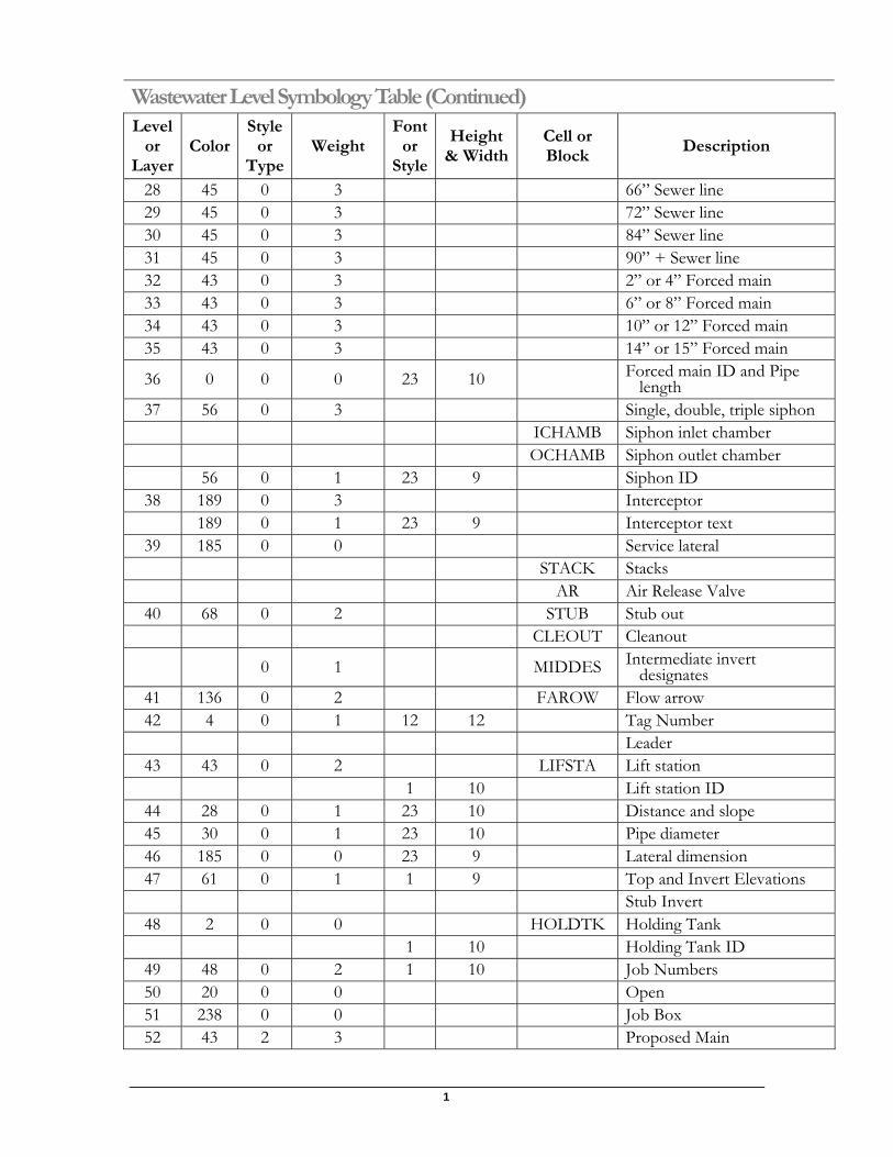
28 45 0 3 66” Sewer line 29 45 0 3 72” Sewer line 30 45 0 3 84” Sewer line 31 45 0 3 90” + Sewer line 32 43 0 3 2” or 4” Forced main 33 43 0 3 6” or 8” Forced main 34 43 0 3 10” or 12” Forced main 35 43 0 3 14” or 15” Forced main
36 0 0 0 23 10 Forced main ID and Pipe length
37 56 0 3 Single, double, triple siphon ICHAMB Siphon inlet chamber OCHAMB Siphon outlet chamber 56 0 1 23 9 Siphon ID
38 189 0 3 Interceptor 189 0 1 23 9 Interceptor text
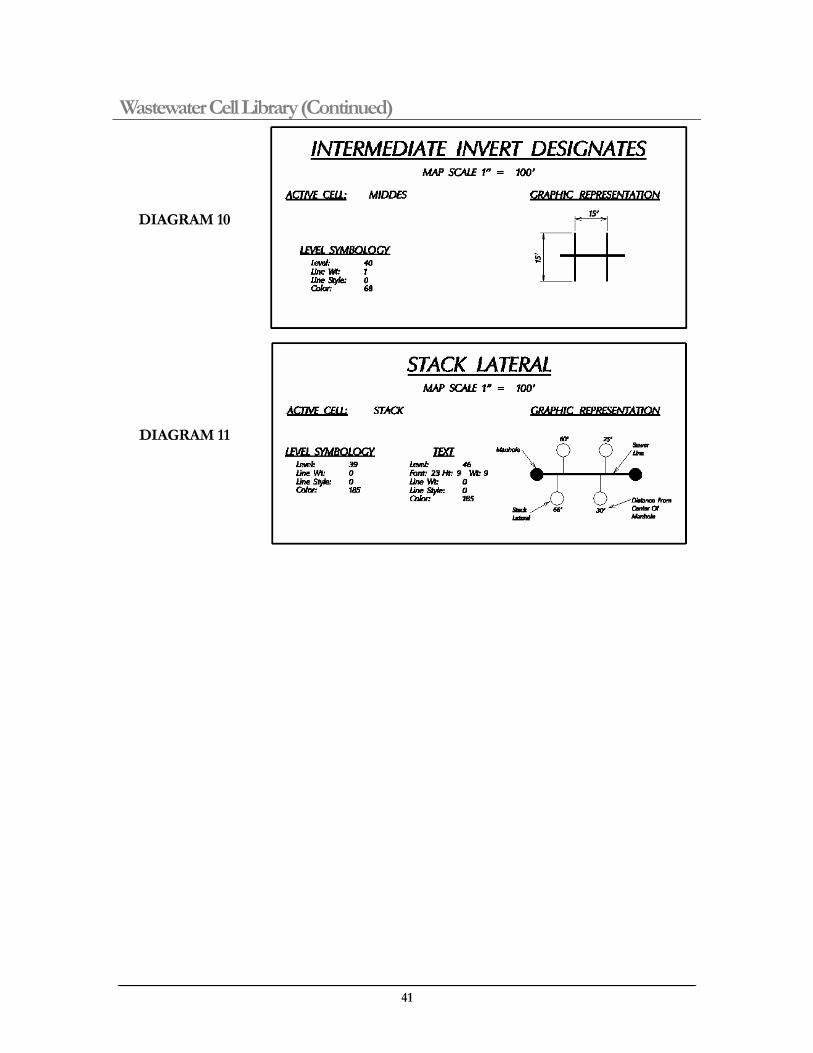
39 185 0 0 Service lateral STACK Stacks AR Air Release Valve
40 68 0 2 STUB Stub out CLEOUT Cleanout
0 1 MIDDES Intermediate invert designates
41 136 0 2 FAROW Flow arrow 42 4 0 1 12 12 Tag Number Leader
43 43 0 2 LIFSTA Lift station 1 10 Lift station ID
44 28 0 1 23 10 Distance and slope 45 30 0 1 23 10 Pipe diameter 46 185 0 0 23 9 Lateral dimension 47 61 0 1 1 9 Top and Invert Elevations Stub Invert
48 2 0 0 HOLDTK Holding Tank 1 10 Holding Tank ID
49 48 0 2 1 10 Job Numbers 50 20 0 0 Open 51 238 0 0 Job Box 52 43 2 3 Proposed Main
41
Wastewater Level Symbology Table (Continued) Level
or Layer
Color Style
or Type
Weight Font
or Style
Height & Width
Cell or Block
Description
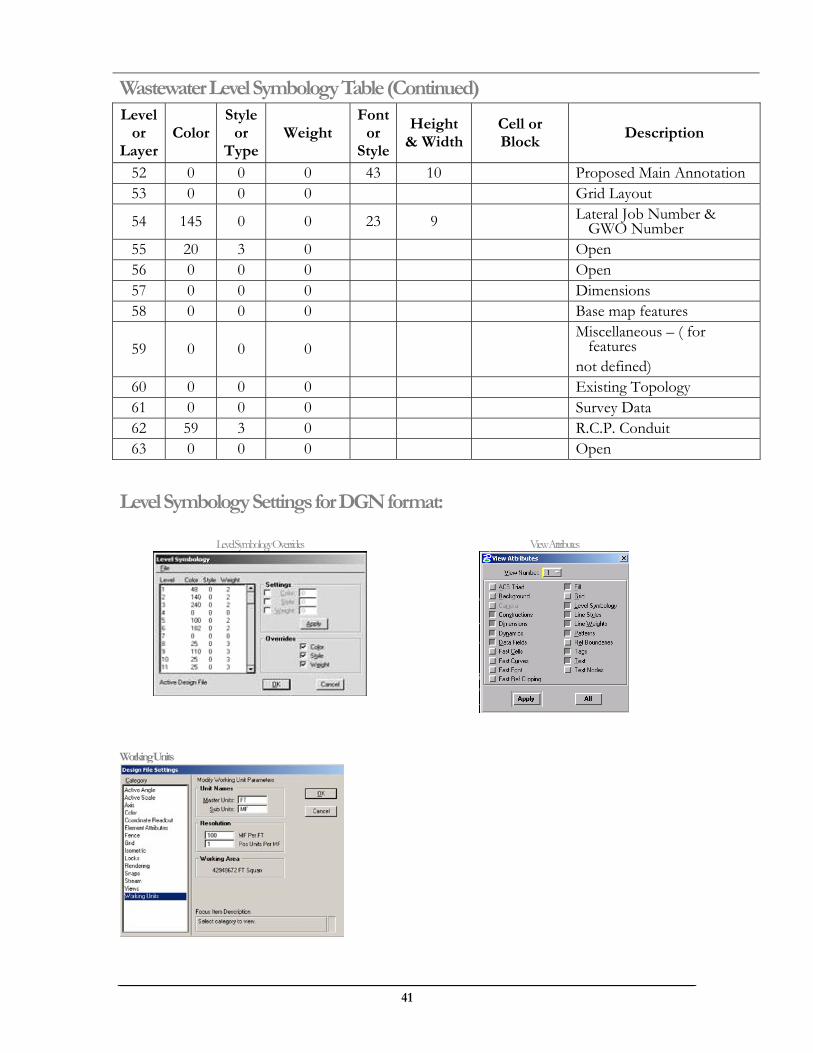
52 0 0 0 43 10 Proposed Main Annotation 53 0 0 0 Grid Layout
54 145 0 0 23 9 Lateral Job Number & GWO Number
55 20 3 0 Open 56 0 0 0 Open 57 0 0 0 Dimensions 58 0 0 0 Base map features
59 0 0 0 Miscellaneous – ( for
features not defined)
60 0 0 0 Existing Topology 61 0 0 0 Survey Data 62 59 3 0 R.C.P. Conduit 63 0 0 0 Open
Level Symbology Settings for DGN format:
Working Units
Level Symbology Overrides View Attributes
1
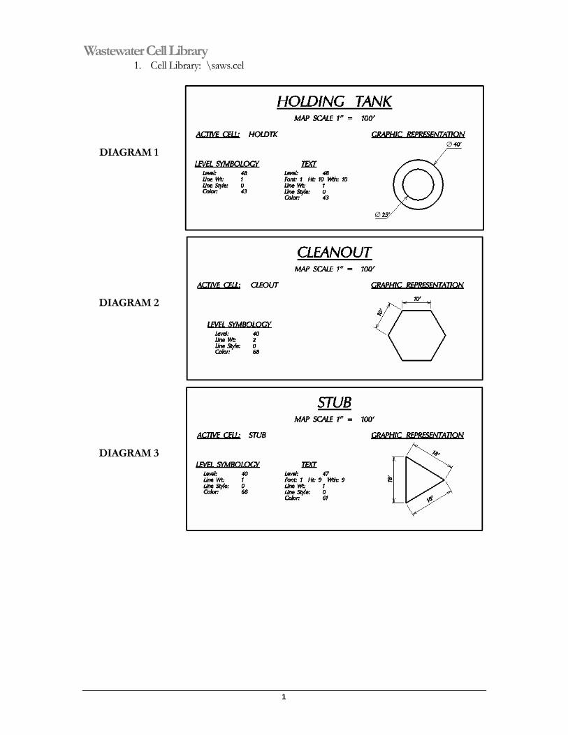
Wastewater Cell Library 1. Cell Library: \saws.cel
DIAGRAM 1
DIAGRAM 2
DIAGRAM 3
41
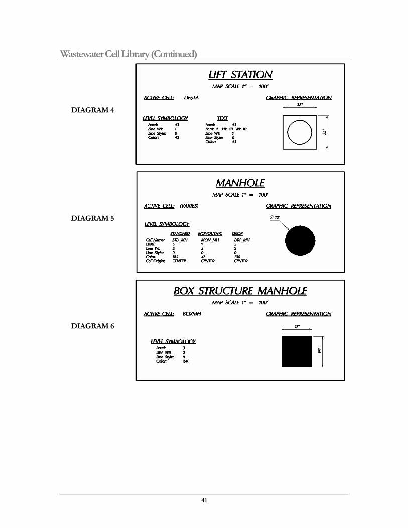
Wastewater Cell Library (Continued)
DIAGRAM 4
DIAGRAM 5
DIAGRAM 6
1
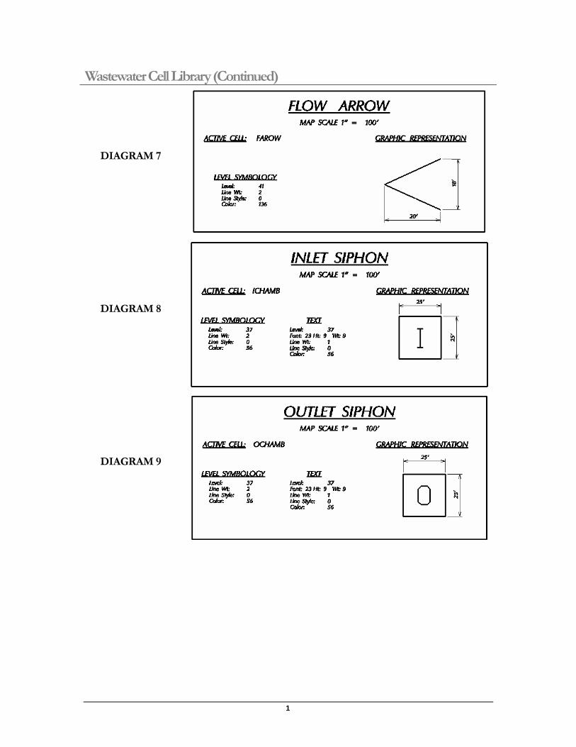
Wastewater Cell Library (Continued)
DIAGRAM 7
DIAGRAM 8
DIAGRAM 9
41
Wastewater Cell Library (Continued)
DIAGRAM 10
DIAGRAM 11
1
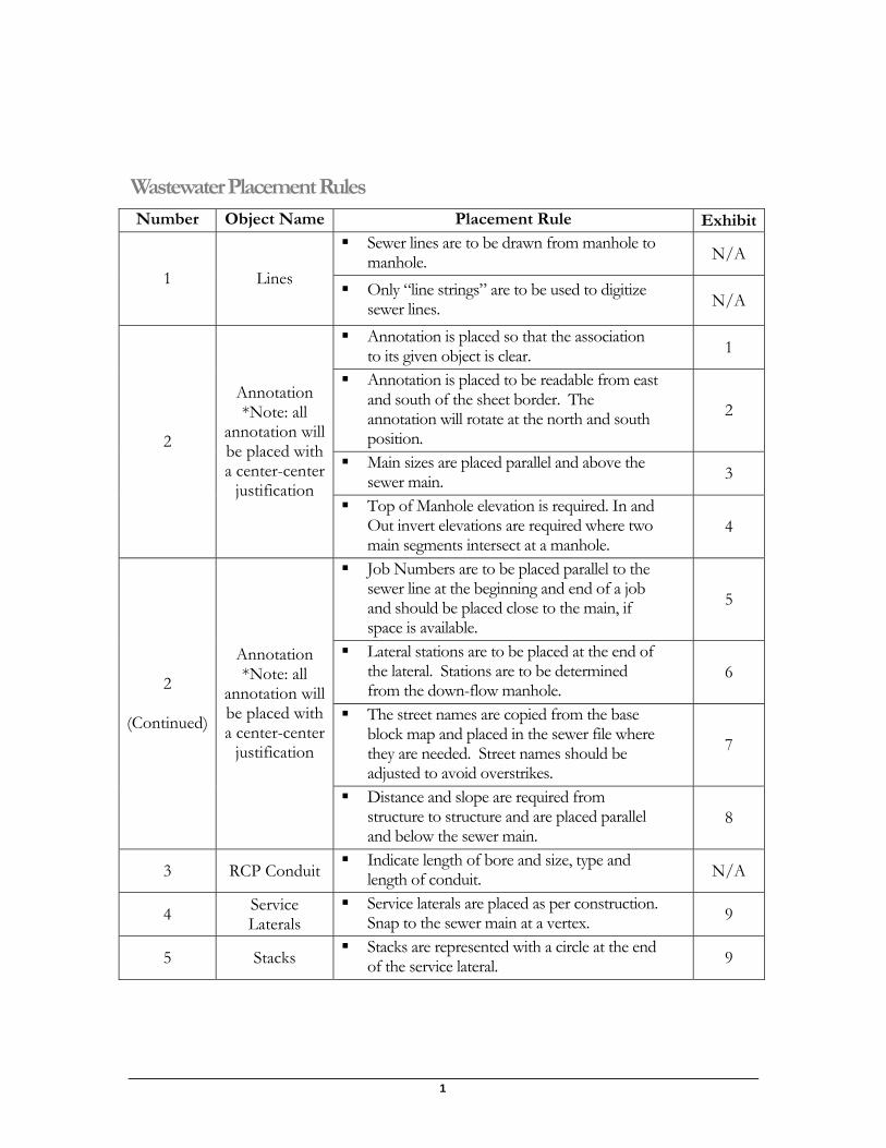
Wastewater Placement Rules Number Object Name Placement Rule Exhibit
Sewer lines are to be drawn from manhole to manhole. N/A
1 Lines Only “line strings” are to be used to digitize sewer lines. N/A
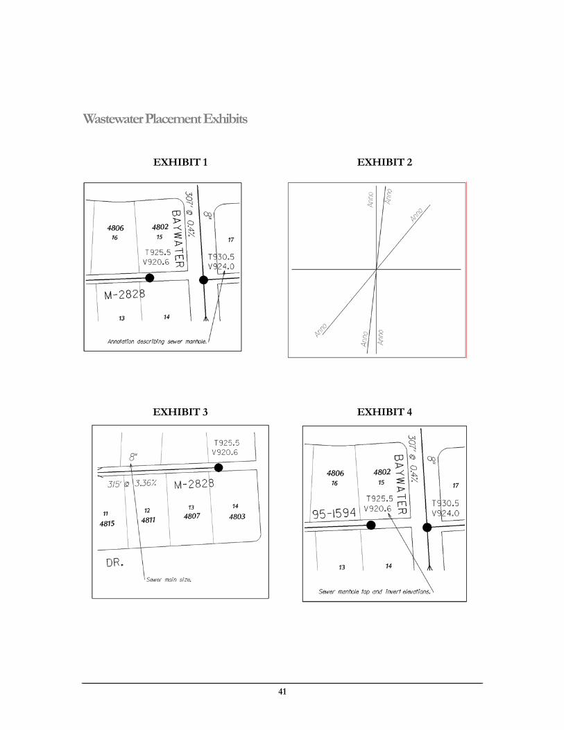
Annotation is placed so that the association to its given object is clear. 1
Annotation is placed to be readable from east and south of the sheet border. The annotation will rotate at the north and south position.
2
Main sizes are placed parallel and above the sewer main. 3
2
Annotation *Note: all
annotation will be placed with a center-center
justification Top of Manhole elevation is required. In and
Out invert elevations are required where two main segments intersect at a manhole.
4
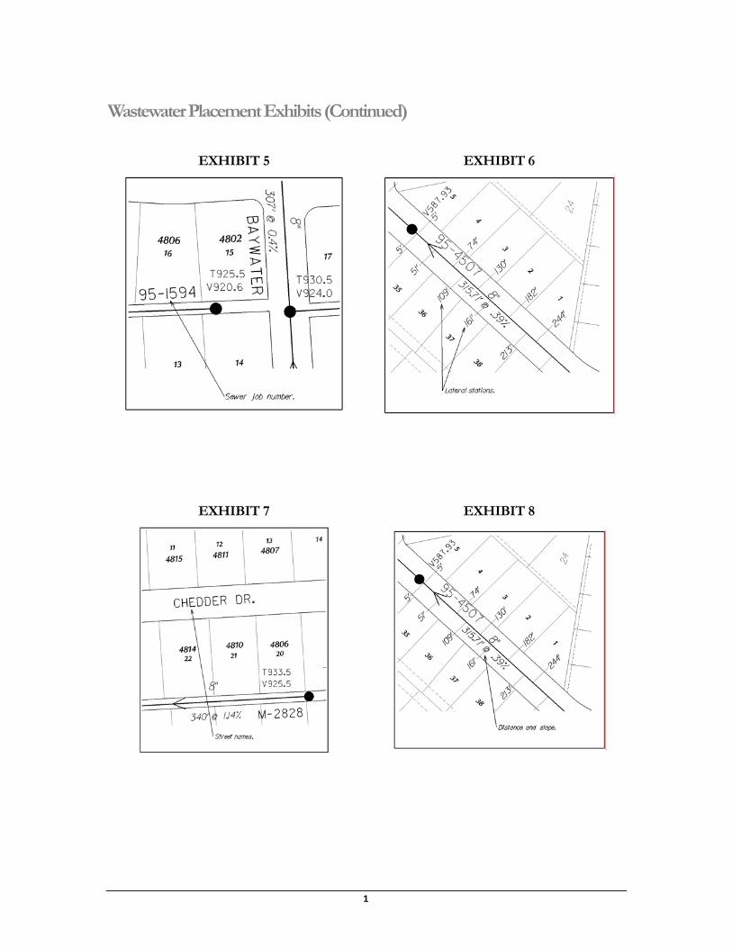
Job Numbers are to be placed parallel to the sewer line at the beginning and end of a job and should be placed close to the main, if space is available.
5
Lateral stations are to be placed at the end of the lateral. Stations are to be determined from the down-flow manhole.
6
The street names are copied from the base block map and placed in the sewer file where they are needed. Street names should be adjusted to avoid overstrikes.
7
2
(Continued)
Annotation *Note: all
annotation will be placed with a center-center
justification
Distance and slope are required from structure to structure and are placed parallel and below the sewer main.
8
3 RCP Conduit Indicate length of bore and size, type and length of conduit. N/A
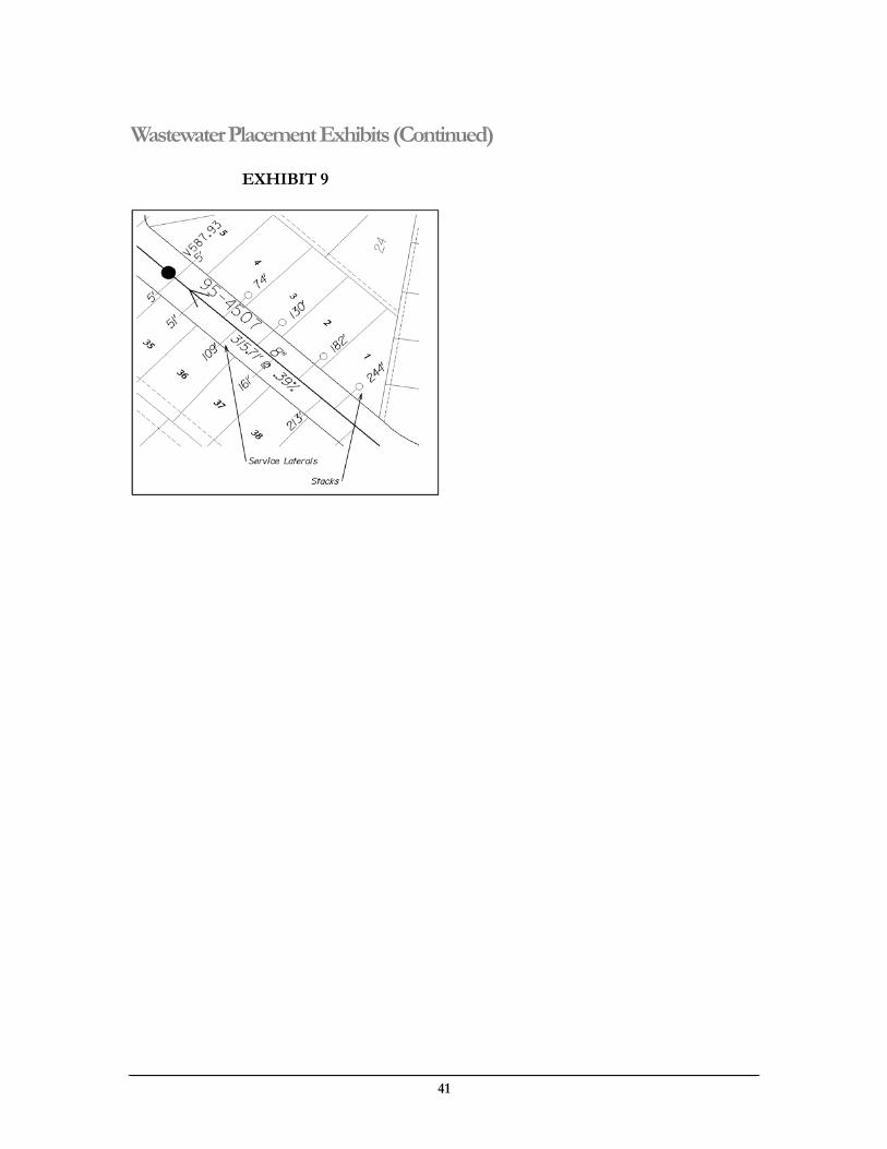
4 Service Laterals
Service laterals are placed as per construction. Snap to the sewer main at a vertex. 9
5 Stacks Stacks are represented with a circle at the end of the service lateral. 9
41
Wastewater Placement Exhibits
EXHIBIT 1 EXHIBIT 2
EXHIBIT 3 EXHIBIT 4
1
Wastewater Placement Exhibits (Continued)
EXHIBIT 5 EXHIBIT 6
EXHIBIT 7 EXHIBIT 8
41
Wastewater Placement Exhibits (Continued)
EXHIBIT 9
1
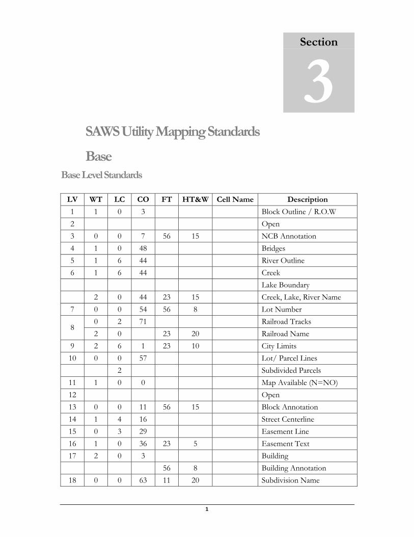
SAWS Utility Mapping Standards
Base Base Level Standards
LV WT LC CO FT HT&W Cell Name Description
1 1 0 3 Block Outline / R.O.W 2 Open 3 0 0 7 56 15 NCB Annotation 4 1 0 48 Bridges 5 1 6 44 River Outline 6 1 6 44 Creek Lake Boundary 2 0 44 23 15 Creek, Lake, River Name 7 0 0 54 56 8 Lot Number
0 2 71 Railroad Tracks 8
2 0 23 20 Railroad Name 9 2 6 1 23 10 City Limits 10 0 0 57 Lot/ Parcel Lines 2 Subdivided Parcels
11 1 0 0 Map Available (N=NO) 12 Open 13 0 0 11 56 15 Block Annotation 14 1 4 16 Street Centerline 15 0 3 29 Easement Line 16 1 0 36 23 5 Easement Text 17 2 0 3 Building 56 8 Building Annotation
18 0 0 63 11 20 Subdivision Name
Section
3
41
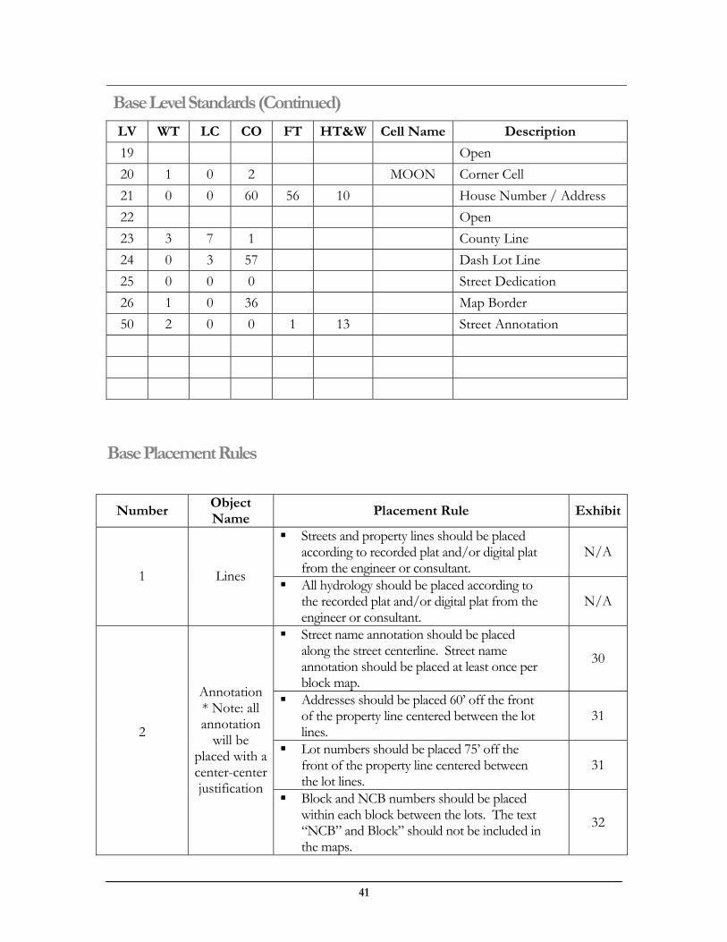
Base Level Standards (Continued)
LV WT LC CO FT HT&W Cell Name Description
19 Open 20 1 0 2 MOON Corner Cell 21 0 0 60 56 10 House Number / Address 22 Open 23 3 7 1 County Line 24 0 3 57 Dash Lot Line 25 0 0 0 Street Dedication 26 1 0 36 Map Border 50 2 0 0 1 13 Street Annotation
Base Placement Rules
Number Object Name
Placement Rule Exhibit
Streets and property lines should be placed according to recorded plat and/or digital plat from the engineer or consultant.
N/A
1 Lines All hydrology should be placed according to the recorded plat and/or digital plat from the engineer or consultant.
N/A
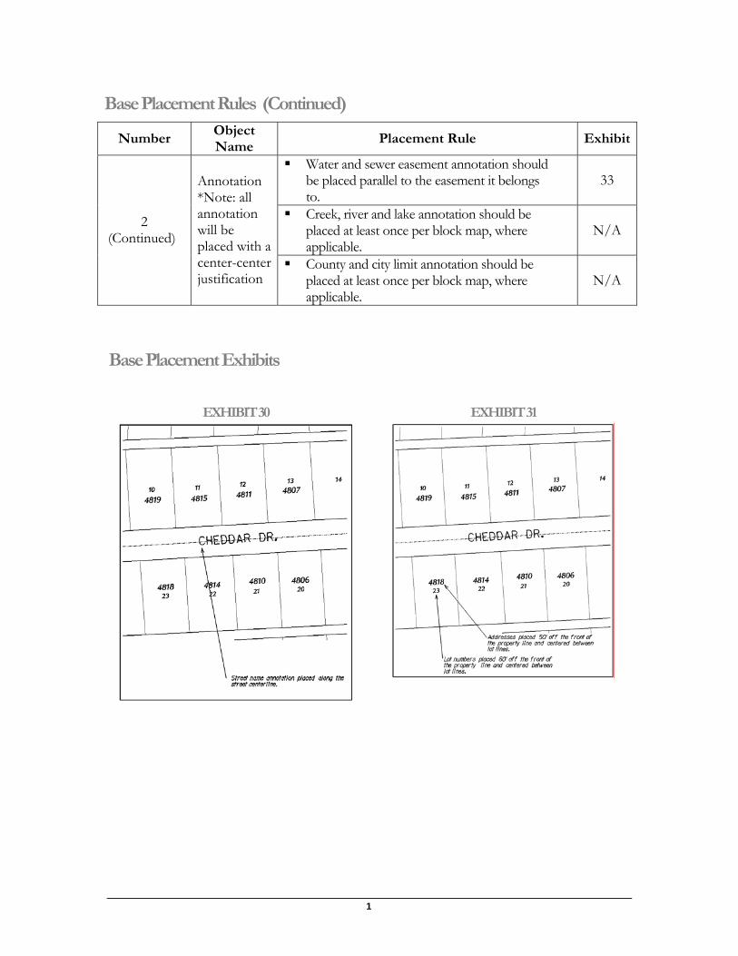
Street name annotation should be placed along the street centerline. Street name annotation should be placed at least once per block map.
30
Addresses should be placed 60’ off the front of the property line centered between the lot lines.
31
Lot numbers should be placed 75’ off the front of the property line centered between the lot lines.
31
2
Annotation * Note: all annotation
will be placed with a center-center justification
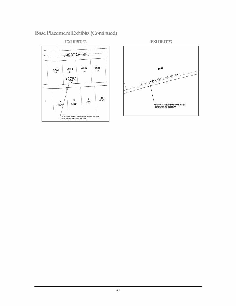
Block and NCB numbers should be placed within each block between the lots. The text “NCB” and Block” should not be included in the maps.
32
1
Base Placement Rules (Continued)
Number Object Name
Placement Rule Exhibit
Water and sewer easement annotation should be placed parallel to the easement it belongs to.
33
Creek, river and lake annotation should be placed at least once per block map, where applicable.
N/A 2 (Continued)
Annotation *Note: all annotation will be placed with a center-center justification
County and city limit annotation should be placed at least once per block map, where applicable.
N/A
Base Placement Exhibits
EXHIBIT 30 EXHIBIT 31
41
Base Placement Exhibits (Continued) EXHIBIT 32 EXHIBIT 33
1
A
Air – Release Valve Cell Diagram .....................................................................14 Placement Exhibit ..............................................................20 Placement Rule..................................................................17
Annotation (Water) Placement Exhibit ..............................................................19 Placement Rule ...................................................................16
B
Base Level Standards ..............................................................35, 36 Placement Exhibits.........................................................37, 38 Placement Rules .............................................................36, 37
Bend – 1/16 Cell Diagram .....................................................................13 Placement Exhibit ..............................................................22 Placement Rule..................................................................18
Bend – 1/32 Cell Diagram .....................................................................14 Placement Exhibit ..............................................................22 Placement Rule..................................................................18
Bend – 1/4 Cell Diagram .....................................................................13 Placement Exhibit ..............................................................22 Placement Rule..................................................................17
Bend – 1/8 Cell Diagram .....................................................................13 Placement Exhibit ..............................................................22 Placement Rule..................................................................18
Bend – Offset Cell Diagram .....................................................................15 Placement Exhibit ..............................................................23 Placement Rule..................................................................18
Bend – Vertical Cell Diagram .....................................................................11 Placement Exhibit ..............................................................22 Placement Rule..................................................................18
Blow-Off Valve Cell Diagram .....................................................................10 Placement Exhibit ..............................................................20 Placement Rule..................................................................17
Box Structure Manhole Cell Diagram .....................................................................28
C
CADD Standards Base ....................................................................................35 Naming Standards ..................................................................3 Overall Utility Layout Plan ......................................................3 Purpose .................................................................................2 Scope ....................................................................................2 Sewer ..................................................................................24 Supporting Files .....................................................................2 Water ....................................................................................4
Cap Cell Diagram.....................................................................12 Placement Exhibit ..............................................................20 Placement Rule .................................................................17
Cast Coupling Cell Diagram.....................................................................11 Placement Exhibit ..............................................................23 Placement Rule .................................................................18
Cleanout Cell Diagram.....................................................................27
Cross Cell Diagram.....................................................................10 Placement Exhibit ..............................................................23 Placement Rule .................................................................18
D
Division Valve Cell Diagram.....................................................................15 Placement Exhibit ..............................................................21
Dual Service Cell Diagram.....................................................................12 Placement Exhibit ..............................................................20 Placement Rule .................................................................17
F
Fire Hydrant Cell Diagram.......................................................................9 Placement Exhibit ..............................................................19 Placement Rule .................................................................17
Flanged Outlet Placement Exhibit ..............................................................21 Placement Rule .................................................................17
Flow Arrow Cell Diagram.....................................................................29
H
Holding Tank Cell Diagram.....................................................................27
I
Inlet Siphon Cell Diagram.....................................................................29
Intermediate Invert Designates Cell Diagram.....................................................................30
J
Jumper Placement Exhibit ..............................................................23 Placement Rule .................................................................18
41
L
Lift Station Cell Diagram .....................................................................28
M
Mains (Water) Placement Exhibit 1 ...........................................................18 Placement Exhibit 2 ...........................................................18 Placement Exhibit 3 ...........................................................19 Placement Rule ...................................................................16
Manhole Cell Diagram .....................................................................28
O
Outlet Siphon Cell Diagram .....................................................................14 Cell Diagram .....................................................................29
P
Plug Cell Diagram .....................................................................12 Placement Exhibit ..............................................................20 Placement Rule..................................................................17
Pressure Release Valve Cell Diagram .......................................................................9
Pressure Zone Placement Rule..................................................................17
Pump Station Placement Exhibit ..............................................................21 Placement Rule..................................................................17
R
RCP Conduit Placement Exhibit ..............................................................21 Placement Rule..................................................................17
Reducer Cell Diagram .....................................................................10 Placement Exhibit ..............................................................20 Placement Rule..................................................................17
S
Service Line Placement Exhibit ..............................................................21
Sewer (Wastewater) Cell Library ........................................................27, 28, 29, 30 Level Standards........................................................24, 25, 26 Level Symbology..................................................................26 Placement Exhibits...................................................32, 33, 34 Placement Rules...................................................................31 View Attributes ....................................................................26
Service Line Placement Rule .................................................................17
Stack Lateral Cell Diagram.....................................................................30
Stub Cell Diagram.....................................................................27
T
Tapping Sleeve Cell Diagram.....................................................................12
Tee Cell Diagram.....................................................................11 Placement Exhibit ..............................................................22 Placement Rule .................................................................17
V
Valve Cell Diagram.......................................................................9 Placement Exhibit ..............................................................20 Placement Rule .................................................................17
W
Water Cell Library ........................................9, 10, 11, 12, 13, 14, 15 Color Table ...........................................................................8 Level Standards......................................................4, 5, 6, 7, 8 Level Symbology..................................................................8 Placement Exhibits ..............................18, 19, 20, 21, 22, 23 Placement Rules.......................................................16, 17, 18 View Attributes.....................................................................8
Well Cell Diagram.....................................................................15 Placement Exhibit ..............................................................21 Placement Rule .................................................................17

1
Notes

41