Bridge Element Inspection Manual Element Inspection Manual Prepared by Bureau of Bridges and...
78
State of Illinois Illinois Department of Transportation 0526-14, 02/14 Bridge Element Inspection Manual
Transcript of Bridge Element Inspection Manual Element Inspection Manual Prepared by Bureau of Bridges and...
State of IllinoisIllinois Department of Transportation
0526-14, 02/14
Bridge ElementInspection Manual

HARD COPIES UNCONTROLLED
Bridge Element Inspection Manual
Prepared by Bureau of Bridges and Structures Division of Highways
Published by Illinois Department of Transportation
Springfield, Illinois
March 20, 2015 Continually Updated Resource
HARD COPIES UNCONTROLLED

HARD COPIES UNCONTROLLED
Document Control and Revision History
The Illinois Manual for Bridge Element Inspection is owned by the Illinois Department of Transportation Bureau of Bridges and Structures. The guide is reviewed during use and updated by the Bureau of Bridges and Structures, as necessary. All changes in the main body of the manual are identified with a revision date at the top of the element description page. Interim changes are communicated through the Bureau of Bridges and Structures email subscription services. Copies are available electronically on the IDOT web site. Archived versions of this guide are available to examine in the Policy and Research Center, Room 320 of the Hanley Building. Electronic Portable Document Format (PDF) has been selected as the primary distribution format, and the official version of the guide is available on the Policy & Research Center Library site on InsideIDOT. Hard Copy This manual is not distributed in hard copy format. Users of this manual who choose to print a copy of the guide are responsible for ensuring use of the most current version. Revision History
Revision Date Description Approval March 20, 2015 Added Elements:
8174: Unpainted Steel Open Girder Ends Including Diaphragms Below Deck Joints (EA) 8175: Lead Painted Steel Open Girder Ends Including Diaphragms Below Deck Joints (EA) 8176: Non-Lead Painted Steel Open Girder Ends Including Diaphragms Below Deck Joints (EA) 8177: Unpainted Steel Stringer Ends Including Diaphragms Below Deck Joints (EA) 8178: Lead Painted Steel Stringer Ends Including Diaphragms Below Deck Joints (EA) 8179: Non-Lead Painted Steel Stringer Ends Including Diaphragms Below Deck Joints (EA) 8362: Pier Settlement 8363: Pier Scour
Steve Beran
Revised Elements:
8171: Unpainted Steel Closed/Box Girder Ends Including Diaphragms Below Deck Joints (EA) 8172: Lead Painted Steel Closed/Box Girder Ends
HARD COPIES UNCONTROLLED
Including Diaphragms Below Deck Joints (EA) 8173: Non-Lead Painted Steel Closed/Box Girder Ends Including Diaphragms Below Deck Joints (EA) 8360: Abutment Settlement 8361: Abutment Scour
Revised Condition State Descriptions for Protection
System Unpainted Steel Elements, page 15, Protection System Lead Painted Steel Elements, page 16, Protection System Non-Lead Painted Steel Elements page 17
HARD COPIES UNCONTROLLED

HARD COPIES UNCONTROLLED
Bridge Element Inspection Manual
March 2015 Page i
TABLE OF CONTENTS Revised 03/14/14
Page # A) BRIDGE DECKS / SLAB 1 Bare 1 Unprotected W/HMA Overlay 2 Protected W/HMA Overlay 3 Protected W/Thin (<1”) Overlay 4 Protected W/Rigid (>1”) Overlay 5 Coated Bars 6 Cathodic Protection 7 Open Grid Deck 8 Filled Grid Deck 9 Filled Grid Deck w/HMA Overlay 10 Corrugated/Orthotropic Deck 11 Timber Deck/Slab Bare 12 Timber Deck/Slab Overlay 13 Sidewalk 14 B) STEEL ELEMENTS 15 Protection System Unpainted 15 Protection System Lead Painted 16 Protection System Non-Lead Painted 17 Steel Damaged Elements 18 C) CONCRETE ELEMENTS 19 Precast and Precast Prestreessed 19 Reinforced Concrete Elements 20 Keyway 21 D) TIMBER ELEMENTS 22 E) CABLES 23 F) “OTHER” SUBSTRUCTURE MATERIALS 24 G) CULVERTS 25 Steel 25 Concrete 26 Other 27 H) JOINTS 28 Strip Seal 28 Pourable 29 Preformed 30 Modular 31 Open 32 Finger 33 Trough Finger 34 Neoprene 35 Continuous Seal Neoprene 36
HARD COPIES UNCONTROLLED
Bridge Element Inspection Manual
Page ii March 2015
I) BEARINGS 37 Elastomeric 37 Steel 38 Steel Below Joints 39 Cluster 40 Fixed 41 Pot 42 J) APPROACHES 43 Spans 43 Pavement 44 K) BRIDGE RAILING 45 Metal 45 Concrete 46 Timber 47 Other 48 L) SCOUR/EROSION/SETTLEMENT 49-50 M) ENVIRONMENT DESCRIPTIONS 51 ALPHABETICAL INDEX 52 NUMERICAL INDEX ` 56 APPENDIX 60
HARD COPIES UNCONTROLLED
Bridge Element Inspection Manual
March 2015 Page 1
CONCRETE DECK/SLAB BARE 11/12/2013
These elements include: Unprotected bare concrete, which receives direct traffic loads. Precast and precast prestressed beams top surfaces are included in element 8034. The top flange of cast in place reinforced concrete T-beams, as well as, reinforced concrete slabs are included in element 8038. The evaluated portions of the bridge deck include all traffic lanes and shoulders. Deck portions not to be evaluated include sidewalks, parapets, medians and other areas, which are not expected to receive direct traffic loads. Elem # Description 12 Concrete Deck Bare (SF) 8034 Precast Concrete Deck Bare (SF) 8038 Concrete Slab Bare (SF) 8056 Precast Concrete Deck w/Rigid 5” Overlay (SF) Condition State 1 The deck surface and soffit have no deficiencies. There are no spalled/delaminated, or map cracked areas in the deck surface. There are no map cracked, spalled/delaminated areas, or stalactitic leaching cracks in the deck soffit. Sound previously repaired areas may exist in the deck surface or soffit. Asphalt repairs are not considered sound repairs. Feasible actions: 1) DN 2) *Wash 3) *Add a protective system and wearing surface Condition State 2 Map cracked areas, intersecting longitudinal and transverse cracks, parallel cracks at 2’ centers or less, spalls/delaminations not associated with corroding reinforcement or stalactitic leaching cracks exist in the deck surface and/or soffit. Feasible actions: 1) DN 2) Seal or inject cracks 3) *Add a protective system and wearing surface Condition State 3 Spalls/delaminations exposing reinforcement exist in the deck surface or soffit. Feasible actions: 1) DN 2) Partial depth repair 3) *Replace deck Condition State 4 Spalled/delaminated, map cracked, or intersecting longitudinal and transverse cracked areas in the deck surface are positioned directly above spalls/delaminations, map cracked, intersecting crack or stalactitic leaching crack areas in the soffit. Condition state 2 or 3 areas in the deck surface are positioned directly above condition state 2 or 3 areas in the soffit. Specifically excluded from this condition state are areas which contain parallel cracks extending through the top to the bottom of the deck, these areas remain in condition state 2, unless accompanied by additional deficiencies. Feasible actions: 1) DN 2) Full depth repair 3) *Replace deck
HARD COPIES UNCONTROLLED
Bridge Element Inspection Manual
Page 2 March 2015
CONCRETE DECK/SLAB UNPROTECTED W/HMA OVERLAY 11/12/2013
These elements include: HMA overlaid and bituminous sealed concrete decks/slabs without a waterproof membrane system, which receive direct traffic loads. Precast and precast prestressed beams top surfaces are included in element 8035. The top flange of cast in place reinforced concrete T-beams, as well as, reinforced concrete slabs are included in element 8039. The evaluated portions of the bridge deck include all traffic lanes and shoulders. Deck portions not to be evaluated include sidewalks, parapets, medians and other areas, which are not expected to receive direct traffic loads. Elem # Description 8013 Concrete Deck Unprotected w/ HMA Overlay (SF) 8035 Precast Concrete Deck Unprotected w/ HMA Overlay (SF) 8039 Concrete Slab Unprotected w/ HMA Overlay (SF) Condition State 1 The deck surface and soffit have no deficiencies. There are no potholes, spalled/delaminated or map cracked areas in the deck surface. There are no map cracked, spalled/delaminated areas, or stalactitic leaching cracks in the deck soffit. Sound previously repaired areas may exist in the deck surface or soffit. Cold patch repairs are not considered sound repairs. Square cut hot mix and concrete repairs are sound repairs. Feasible actions: 1) DN 2) *Wash Condition State 2 Potholes, map cracked areas, parallel cracks at 2’ centers or less, intersecting cracks, spalls/delaminations not associated with corroding reinforcement or stalactitic leaching cracks exist in the deck surface and/or soffit. Feasible actions: 1) DN 2) Patch holes, seal or inject cracks 3) *Remove overlay, add protection system and wearing surface Condition State 3 Large potholes, large ruts or washboards, in the deck surface or spalls/delaminations exposing reinforcement in the concrete deck or soffit exist. Feasible actions: 1) DN 2) Partial depth repair 3) *Replace Deck Condition State 4 Large potholes, large ruts, washboard, repairs, spalled/delaminated, map cracked or intersecting longitudinal and transverse cracked areas in the deck surface and/or subsurface are positioned directly above spalls/delaminations, map cracked, intersecting cracks or stalactitic leaching crack areas in the soffit. Condition state 2 or 3 areas in the deck surface are positioned directly above condition state 2 or 3 areas in the soffit. Specifically excluded from this condition state are areas which contain parallel cracks extending through the top to the bottom of the deck, these areas remain in condition state 2, unless accompanied by additional deficiencies. Feasible actions: 1) DN 2) Full depth repair 3) *Replace deck
HARD COPIES UNCONTROLLED
Bridge Element Inspection Manual
March 2015 Page 3
CONCRETE DECK/SLAB PROTECTED W/ HMA OVERLAY 11/12/2013
These elements include: HMA overlaid concrete decks/slabs with a waterproof membrane system, which receive direct traffic loads. Precast and precast prestressed beams top surfaces are included in element 8036. The top flange of cast in place reinforced concrete T-beams, as well as, reinforced concrete slabs are included in element 8040. The evaluated portions of the bridge deck include all traffic lanes and shoulders. Deck portions not to be evaluated include sidewalks, parapets, medians and other areas, which are not expected to receive direct traffic loads. Elem # Description 8014 Concrete Deck Protected w/ HMA Overlay (SF) 8036 Precast Concrete Deck Protected w/HMA Overlay (SF) 8040 Concrete Slab Protected w/ HMA Overlay (SF) Condition State 1 The deck surface and soffit have no deficiencies. There are no potholes, spalled/delaminated or map cracked areas in the deck surface. There are no map cracked, spalled/delaminated areas, or stalactitic leaching cracks in the deck soffit. Sound previously repaired areas may exist in the deck surface or soffit. Cold patch repairs are not considered sound repairs. Square cut hot mix and concrete repairs are sound repairs. Feasible actions: 1) DN 2) *Wash Condition State 2 Potholes, map cracked areas, intersecting cracks, parallel cracks at 2’ centers or less, stalactitic leaching cracks or surface spalls/delamination without reinforcement corrosion exist in the deck surface and/or soffit. Feasible actions: 1) DN 2) Patch holes, seal or inject cracks 3) *Remove overlay, add protection system and wearing surface Condition State 3 Large potholes, large ruts or washboards, in the deck surface or spalls/delaminations exposing reinforcement in the concrete deck or soffit exist. Feasible actions: 1) DN 2) Partial depth repair 3) *Replace deck Condition State 4 Large potholes, large ruts, washboard, repairs, spalled/delaminated, map cracked or intersecting longitudinal and transverse cracked areas in the deck surface and/or subsurface are positioned directly above spalls/delaminations, map cracked, intersecting cracks or stalactitic leaching crack areas in the soffit. Condition state 2 or 3 areas in the deck surface are positioned directly above condition state 2 or 3 areas in the soffit. Specifically excluded from this condition state are areas which contain parallel cracks extending through the top to the bottom of the deck, these areas remain in condition state 2, unless accompanied by additional deficiencies. Feasible actions: 1) DN 2) Full depth repair 3) *Replace deck
HARD COPIES UNCONTROLLED
Bridge Element Inspection Manual
Page 4 March 2015
CONCRETE DECK/SLAB PROTECTED W/ THIN (<1") OVERLAY 09/30/2013
These elements include: Concrete decks/slabs that have a less than 1 inch thick cementitious overlay which receive direct traffic loads. The top flange of cast in place reinforced concrete T-beams, as well as, reinforced concrete slabs are included in element 8044. All other decks protected with thin overlays, including precast beams, are included in element 8018. The evaluated portions of the bridge deck include all traffic lanes and shoulders. Deck portions not to be evaluated include sidewalks, parapets, medians and other areas, which are not expected to receive direct traffic loads. Elem # Description 8018 Concrete Deck Protected w/ Thin Overlay (SF) 8044 Concrete Slab Protected w/ Thin Overlay (SF) Condition State 1 The deck surface and soffit have no deficiencies. There are no spalled/delaminated, map cracked areas in the deck surface. There are no map cracked, spalled/delaminated areas, or stalactitic leaching cracks in the deck soffit. Sound previously repaired areas may exist in the deck surface or soffit. Asphalt repairs are not considered sound repairs. Feasible actions: 1) DN 2) *Wash 3) *Add overlay Condition State 2 Map cracked areas, intersecting longitudinal and transverse cracks, parallel cracks at 2’ centers or less, or stalactitic leaching cracks, spalls/delaminations are not associated with corroding reinforcement exist in the deck surface and/or soffit. Feasible actions: 1) DN 2) Seal or inject cracks 3) *Add overlay Condition State 3 Spalls/delaminations exposing reinforcement exist in the deck surface or soffit. Feasible actions: 1) DN 2) Partial depth repair 3) *Replace deck Condition State 4 Spalled/delaminated, map cracked, or intersecting longitudinal and transverse cracked areas in the deck surface are positioned directly above spalls/delaminations, map cracked, intersecting cracks or stalactitic leaching crack areas in the soffit. Conditions state 2 or 3 areas in the deck surface are positioned directly above condition state 2 or 3 areas in the soffit. Specifically excluded from this condition state are areas which contain parallel cracks extending through the top to the bottom of the deck, these areas remain in condition state 2, unless accompanied by additional deficiencies. Feasible actions: 1) DN 2) Full depth repair 3) *Replace deck
HARD COPIES UNCONTROLLED
Bridge Element Inspection Manual
March 2015 Page 5
CONCRETE DECK/SLAB PROTECTED W/ RIGID (>1") OVERLAY 09/30/2013
These elements include: Concrete decks/slabs that have a rigid overlay 1 inch thick or greater which receive direct traffic loads. The top flange of cast in place reinforced concrete T-beams, as well as, reinforced concrete slabs are included in element 8048. All other decks protected with overlays, including precast beams, are included in element 8022. The evaluated portions of the bridge deck include all traffic lanes and shoulders. Deck portions not to be evaluated include sidewalks, parapets, medians and other areas, which are not expected to receive direct traffic loads. Elem # Description 8022 Concrete Deck Protected w/ Rigid Overlay (SF) 8048 Concrete Slab Protected w/ Rigid Overlay (SF) Condition State 1 The deck surface and soffit have no deficiencies. There are no spalled/delaminated, or map cracked areas in the deck surface. There are no map cracked, spalled/delaminated areas, or stalactitic leaching cracks in the deck soffit. Sound previously repaired areas may exist in the deck surface or soffit. Asphalt repairs are not considered sound repairs. Feasible actions: 1) DN 2) *Wash Condition State 2 Map cracked areas, intersecting longitudinal and transverse cracks, parallel cracks at 2’ centers or less, spalls/delaminations not associated with corroding reinforcement, or stalactitic leaching cracks exist in the deck surface and/or soffit. Feasible actions: 1) DN 2) Seal or inject cracks Condition State 3 Spalls/delaminations exposing reinforcement exist in the deck surface or soffit. Feasible actions: 1) DN 2) Partial depth repair 3) *Replace deck Condition State 4 Spalled/delaminated, map cracked, or intersecting longitudinal and transverse cracked areas in the deck surface are positioned directly above spalls/delaminations, map cracked, intersecting cracks or stalactitic leaching crack areas in the soffit. Condition state 2 or 3 areas in the deck surface are positioned directly above condition state 2 or 3 areas in the soffit. Specifically excluded from this condition state are areas which contain parallel cracks extending through the top to the bottom of the deck, these areas remain in condition state 2, unless accompanied by additional deficiencies. Feasible actions: 1) DN 2) Full depth repair 3) *Replace deck
HARD COPIES UNCONTROLLED
Bridge Element Inspection Manual
Page 6 March 2015
CONCRETE DECK/SLAB COATED BARS 09/30/2013
These elements include: Bare concrete decks/slabs that are protected with epoxy coated bars, which receive direct traffic loads. The evaluated portions of the bridge deck include all traffic lanes and shoulders. Deck portions not to be evaluated include sidewalks, parapets, medians and other areas, which are not expected to receive direct traffic loads. Elem # Description 8026 Concrete Deck Protected w/ Coated Bars (SF) 8033 Concrete Deck Protected w/ Coated Bars w/ PPC Panels (SF) 8052 Concrete Slab Protected w/ Coated Bars (SF) Condition State 1 The deck surface and soffit have no deficiencies. There are no spalled/delaminated, or map cracked areas in the deck surface. There are no map cracked, spalled/delaminated areas or stalactitic leaching cracks in the deck soffit. Sound previously repaired areas may exist in the deck surface or soffit. Asphalt repairs are not considered sound repairs. Feasible actions: 1) DN 2) *Wash 3) *Add concrete overlay Condition State 2 Map cracked areas, intersecting longitudinal and transverse cracks, parallel cracks at 2’ centers or less, stalactitic leaching cracks or surface spalls/delaminations without reinforcement corrosion exist in the deck surface and/or soffit. Feasible actions: 1) DN 2) Seal or inject cracks 3) *Add concrete overlay Condition State 3 Spalls/delaminations exposing reinforcement exist in the deck surface or soffit. Feasible actions: 1) DN 2) Partial depth repair 3) *Replace deck Condition State 4 Spalled/delaminated, map cracked, or intersecting longitudinal and transverse cracked areas in the deck surface are positioned directly above spalls/delaminations, map cracked, intersecting cracks or stalactitic leaching crack areas in the soffit. Condition state 2 or 3 areas in the deck surface are positioned directly above condition state 2 or 3 areas in the soffit. Specifically excluded from this condition state are areas which contain parallel cracks extending through the top to the bottom of the deck, these areas remain in condition state 2, unless accompanied by additional deficiencies. Feasible actions: 1) DN 2) Full depth repair 3) *Replace deck
HARD COPIES UNCONTROLLED
Bridge Element Inspection Manual
March 2015 Page 7
CONCRETE DECK/SLAB CATHODIC PROTECTION Revised 03/14/2014
These elements include: Concrete decks/slabs that are protected with cathodic protection which receive direct traffic loads. The evaluated portions of the bridge deck include all traffic lanes and shoulders. Deck portions not to be evaluated include sidewalks, parapets, medians and other areas, which are not expected to receive direct traffic loads. Elem # Description 8027 Concrete Deck Protected w/Cathodic Protection (SF) 8053 Concrete Slab Protected w/Cathodic Protection (SF) Condition State 1 The deck surface and soffit have no deficiencies. There are no spalled/delaminated, or map cracked areas in the deck surface. There are no map cracked, or spalled/delaminated areas, or stalactitic leaching cracks in the deck soffit. Sound previously repaired areas may exist in the deck surface or soffit. Asphalt repairs are not considered sound repairs. Feasible actions: 1) DN 2) *Wash 3) Replace anode Condition State 2 Map cracked areas, intersecting longitudinal and transverse cracks, parallel cracks at 2’ centers or less, spalls/delaminations not associated with corroding reinforcement or stalactitic leaching cracks exist in the deck surface and/or soffit. Feasible actions: 1) DN 2) Seal or inject cracks 3) Repair cathodic protection Condition State 3 Spalls/delaminations exposing reinforcement exist in the deck surface or soffit. Feasible actions: 1) DN 2) Repair cathodic protection 3) *Replace deck Condition State 4 Spalled/delaminated, map cracked, or intersecting longitudinal and transverse cracked areas in the deck surface are positioned directly above spalls/delaminations, map cracked, intersecting cracks or stalactitic leaching crack areas in the soffit. Condition state 2 or 3 areas in the deck surface are positioned directly above condition state 2 or 3 areas in the soffit. Specifically excluded from this condition state are areas which contain parallel cracks extending through the top to the bottom of the deck, these areas remain in condition state 2, unless accompanied by additional deficiencies. Feasible actions: 1) DN 2) *Replace cathodic protection 3) *Replace deck
HARD COPIES UNCONTROLLED
Bridge Element Inspection Manual
Page 8 March 2015
OPEN GRID DECK 11/12/2013
This element includes: Steel open grid decks, which receive direct traffic loads. The evaluated portions of the bridge deck include all traffic lanes and shoulders. Deck portions not to be evaluated include sidewalks, parapets, medians and other areas, which are not expected to receive direct traffic loads. Elem # Description 28 Steel Deck Open Grid (SF) Condition State 1 The deck has no deficiencies. There is no corrosion. The paint system is sound. All connections are sound. Feasible actions: 1) DN 2) *Wash Condition State 2 The paint system has failed, and corrosion has formed or secondary connectors show cracked welds or broken rivets or bolts. Feasible actions: 1) DN 2) *Wash 3) *Wash and paint or reconnect Condition State 3 Measurable corrosion or connections have failed on secondary grid or primary connections show cracks. Feasible actions: 1) DN 2) *Wash 3) *Wash and paint or reconnect Condition State 4 Measurable corrosion or connections to the floor system have failed on the primary grid. Feasible actions: 1) DN 2) Spot blast, clean and paint or reconnect 3) *Replace deck
HARD COPIES UNCONTROLLED
Bridge Element Inspection Manual
March 2015 Page 9
FILLED GRID DECK 11/12/2013
This element includes: Steel grid decks filled with concrete, which receive direct traffic loads. The evaluated portions of the bridge deck include all traffic lanes and shoulders. Deck portions not to be evaluated include sidewalks, parapets, medians and other areas, which are not expected to receive direct traffic loads. Elem # Description 29 Steel Deck Concrete Filled Grid (SF) Condition State 1 The deck has no deficiencies. There is no corrosion. The paint system is sound. The deck has no delaminations. Connections are sound. Feasible actions: 1) DN 2) *Wash Condition State 2 The paint system has failed and corrosion has formed or secondary connectors show cracked welds or broken rivets or bolts. If present, wearing surface has map cracked areas, intersecting longitudinal and transverse cracks. Feasible actions: 1) DN 2) *Wash 3) *Wash and paint or reconnect Condition State 3 Grid fill is spalling, secondary grid connections have failed or have measurable corrosion, or primary connections show cracks. Feasible actions: 1) DN 2) Repair deficient areas 3) *Replace deck Condition State 4 Grid fill has large spalls, measurable corrosion or connections to the floor system have failed on the primary grid. Feasible actions: 1) DN 2) Repair deficient areas 3) *Replace deck
HARD COPIES UNCONTROLLED
Bridge Element Inspection Manual
Page 10 March 2015
FILLED GRID DECK w/HMA OVERLAY 11/12/2013
This element includes: Steel grid decks filled with concrete, which receive direct traffic loads. The evaluated portions of the bridge deck include all traffic lanes and shoulders. Deck portions not to be evaluated include sidewalks, parapets, medians and other areas, which are not expected to receive direct traffic loads. Elem # Description 8057 Steel Deck Concrete Filled Grid w/HMA Overlay (SF) Condition State 1 The deck surface and soffit have no deficiencies. There are no potholes, spalled/delaminated, or map cracked areas in the deck surface. The protection system of the deck soffit is sound. Previously repaired/repainted areas may exist in the deck surface or soffit. There is no corrosion. The paint system is sound. Connections are sound. Feasible actions: 1) DN 2) *Wash Condition State 2 Potholes, map cracked areas, parallel cracks at 2’ centers or less, or intersecting cracks exist in the deck surface or the underside protection system is being affected. The paint system has failed and corrosion has formed or secondary connectors show cracked welds or broken rivets or bolts. Feasible actions: 1) DN 2) *Wash 3) *Wash and paint or reconnect Condition State 3 Large potholes, large ruts or washboard areas in the deck surface or the soffit is corroding. Secondary grid connections have failed or have measurable corrosion, or primary connections show cracks. Feasible actions: 1) DN 2) Repair deficient areas 3) *Replace deck Condition State 4 The surfacing has failed, grid fill has large spalls, measurable corrosion or connections to the floor system have failed on the primary grid. Feasible actions: 1) DN 2) Repair deficient areas 3) *Replace deck
HARD COPIES UNCONTROLLED
Bridge Element Inspection Manual
March 2015 Page 11
CORRUGATED/ORTHOTROPIC DECK 08/19/2013
This element includes: Steel decks, which support traffic loads. Included are the tops of steel box superstructures and asphalt filled corrugated decks. Orthotropic deck paint condition and corrosion should be reported with the superstructure element. This element does not include: Stay in place corrugated steel forms used to temporarily support concrete decks during placement. Steel stay in place forms should be evaluated as the soffit of the concrete deck element. Elem # Description 30 Corrugated/Orthotropic/Etc. Deck (SF) Condition State 1 The deck surface and soffit have no deficiencies. There are no potholes, spalled/delaminated, or map cracked areas in the deck surface. The protection system of the deck soffit is sound. Previously repaired/repainted areas may exist in the deck surface or soffit. Feasible actions: 1) DN 2) *Wash Condition State 2 Potholes, map cracked areas, parallel cracks at 2’ centers or less, or intersecting cracks exist in the deck surface or the underside protection system is being affected. Feasible actions: 1) DN 2) Patch holes, seal cracks 3) *Remove overlay, add protection system and wearing surface Condition State 3 Large potholes, large ruts or washboard areas in the deck surface or the soffit is corroding but no measurable section loss. Feasible actions: 1) DN 2) Patch holes and seal cracks 3) *Remove overlay, add protection system and wearing surface Condition State 4 Corrosion is advanced. Measurable section loss warrants analysis to ascertain the impact on the ultimate strength and/or serviceability of either the element or the bridge. The surfacing has failed. Feasible actions: 1) DN 2) *Rehabilitate, replace paint system, replace surfacing 3) *Replace deck
HARD COPIES UNCONTROLLED
Bridge Element Inspection Manual
Page 12 March 2015
TIMBER DECK/SLAB BARE 10/18/1995
These elements include: Bare timber decks/slabs, which receive direct traffic loads. The evaluated portions of the bridge deck include all traffic lanes and shoulders. Deck portions not to be evaluated include sidewalks, parapets, medians and other areas, which are not expected to receive direct traffic loads. Elem # Description 31 Timber Deck Bare (SF) 54 Timber Slab Bare (SF) Condition State 1 The deck has no deficiencies. There may be small cracks, splits and checks having no effect on strength or serviceability. There is no decay, wet areas, and insect infestation. Feasible actions: 1) DN 2) *Clean 3) *Clean and seal Condition State 2 Decay, insect infestation, splitting, cracking or crushing may exist but none is sufficiently advanced to affect serviceability or strength. The deck may be covered with debris or rocks but no serious wearing. Fire damage limited to surface scorching with no measurable section loss. Areas, which collect and hold water intermittently are included. Feasible actions: 1) DN 2) *Clean 3) *Clean and seal Condition State 3 Decay, insect infestation, splitting cracking or crushing has produced loss of strength of the element but not of sufficient magnitude to affect the serviceability of the bridge. Debris or rocks may have caused minor section loss. Fire damage limited to surface charring with minor, measurable section loss. Wet areas with sufficient water present to support fungus growth. Feasible actions: 1) DN 2) *Clean and seal 3) Replace deficient members Condition State 4 Advanced deterioration. Decay, insect infestation, splits, cracks or crushing has produced loss of strength that affects the serviceability of the bridge. Debris or rock may have caused greater than 1/2" deep ruts or wear. Major fire damage which substantially reduces the load-carrying capacity of the deck. Wet areas with possibly green leafy growth growing from the deck. Feasible actions: 1) DN 2) Replace deficient members 3) *Replace deck
HARD COPIES UNCONTROLLED
Bridge Element Inspection Manual
March 2015 Page 13
TIMBER DECK/SLAB OVERLAY 11/12/2013
These elements include: Overlaid timber decks/slabs, which receive direct traffic loads. The evaluated portions of the bridge deck include all traffic lanes and shoulders. Deck portions not to be evaluated include sidewalks, parapets, medians and other areas, which are not expected to receive direct traffic loads. Elem # Description 8032 Timber Deck with HMA Overlay (SF) 8055 Timber Slab with HMA Overlay (SF) Condition State 1 Investigation indicates no decay. There may be cracks, splits and checks having no effect on strength or serviceability. There are no potholes in the surfacing. Feasible actions: 1) DN 2) *Clean Condition State 2 Decay, insect infestation, splitting, cracking or crushing may exist but none is sufficiently advanced to affect serviceability. Potholes, map cracked areas, intersecting cracks exist in the deck surface. Fire damage limited to surface scorching without measurable section loss. Areas, which collect and hold water intermittently are included. Feasible actions: 1) DN 2) *Clean 3) *Remove/replace overlay Condition State 3 Decay, insect infestation, splitting cracking or crushing has produced loss of strength of the element but not of sufficient magnitude to affect the serviceability of the bridge. Large potholes, large ruts or washboards in the deck surface. Fire damage limited to surface charring with minor, measurable section loss. Wet areas with sufficient water present to support fungus growth. Feasible actions: 1) DN 2) *Rehabilitate deck and repair or replace surfacing 3) *Replace deck and surfacing Condition State 4 Advanced deterioration. Decay, insect infestation, splits, cracks or crushing has produced loss of strength that affects the serviceability of the bridge. Large potholes, large ruts, washboards, map cracked areas are positioned above areas of the soffit which show advanced section loss. Major fire damage which substantially reduces the load-carrying capacity of the deck. Wet areas with green leafy growth growing from the deck. Feasible actions: 1) DN 2) *Rehabilitate deck and repair or replace surfacing 3) *Replace deck and surfacing
HARD COPIES UNCONTROLLED
Bridge Element Inspection Manual
Page 14 March 2015
SIDEWALK 11/12/2013
These elements include: Optional element for sidewalks which are not expected to receive direct traffic loads. Elem # Description 8058 Sidewalk (SF) Condition State 1 The sidewalk surface and soffit have no deficiencies. There are no spalled/delaminated, or map cracked areas in the sidewalk surface. There are no map cracked, spalled/delaminated areas, or stalactitic leaching cracks in the sidewalk soffit. Sound previously repaired areas may exist in the sidewalk surface or soffit. Asphalt repairs are not considered sound repairs. Feasible actions: 1) DN 2) *Wash 3) *Add a protective coating system Condition State 2 Map cracked areas, intersecting longitudinal and transverse cracks, parallel cracks at 2’ centers or less, spalls/delaminations not associated with corroding reinforcement or stalactitic leaching cracks exist in the sidewalk surface and/or soffit. Feasible actions: 1) DN 2) Seal or inject cracks 3) *Add a protective coating system Condition State 3 Spalls/delaminations exposing reinforcement exist in the sidewalk surface or soffit. Feasible actions: 1) DN 2) Partial depth repair / Curb Face Concrete Repair 3) *Replace sidewalk Condition State 4 Spalled/delaminated, map cracked, or intersecting longitudinal and transverse cracked areas in the sidewalk surface are positioned directly above spalls/delaminations, map cracked, intersecting crack or stalactitic leaching crack areas in the soffit. Condition state 2 or 3 areas in the sidewalk surface are positioned directly above condition state 2 or 3 areas in the soffit. Specifically excluded from this condition state are areas which contain parallel cracks extending through the top to the bottom of the sidewalk, these areas remain in condition state 2, unless accompanied by additional deficiencies. Feasible actions: 1) DN 2) Full depth repair 3) *Replace sidewalk
HARD COPIES UNCONTROLLED
Bridge Element Inspection Manual
March 2015 Page 15
PROTECTION SYSTEM UNPAINTED STEEL ELEMENTS
03/20/15 These elements include: The protection system of unpainted ASTM 588 or AASHTO M222 steel substructure and superstructure elements that were designed to achieve corrosion protection by a uniform collection of corrosion products on the steel surface. Other Steel chemistries that were installed unpainted or have lost their original paint system will be included with Protection System Non-Lead Painted Steel Elements (p. 17). Elem # Description 8101 Unpainted Steel Closed Web/Box Girder (SF) 8106 Unpainted Steel Open Girder (SF) 8112 Unpainted Steel Stringer (SF) 120 Unpainted Steel Bottom Chord Through Truss (SF) 8125 Unpainted Steel Through Truss Excluding Bottom Chord (SF) 8130 Unpainted Steel Deck Truss (SF) 8140 Unpainted Steel Arch/Arch Tie (SF) 8151 Unpainted Steel Floor Beam (SF) 8160 Unpainted Steel Pin and/or Hanger (EA) 8171 Unpainted Steel Closed Web/Box Girder Ends Including Diaphragms Below Deck Joints (EA) 8174 Unpainted Steel Open Girder Ends Including Diaphragms Below Deck Joints (EA) 8177 Unpainted Steel Stringer Ends Including Diaphragms Below Deck Joints (EA) 8180 Unpainted Steel Deck Truss Below Deck Joints (SF) 8190 Unpainted Steel Floor Beam Below Deck Joints (SF) 8201 Unpainted Steel Column (SF) 8222 Unpainted Steel Abutment and Wingwall (SF) 8224 Unpainted Steel Pile Extension (SF) 8230 Unpainted Steel Pier or Abutment Cap (SF) 8270 Unpainted Steel Pier or Abutment Cap Below Deck Joint (SF)
Condition State 1 The weathering steel is corroded uniformly and remains in excellent condition. Surfaces covered by mill scale are included. Feasible actions: 1) DN 2) *Wash Condition State 2 Surface pitting has formed or is forming on the unpainted steel. Feasible actions: 1) DN 2) *Wash 3) *Clean and paint Condition State 3 Steel has measurable section loss due to corrosion up to 1/16” per face. Feasible actions: 1) DN 2) *Wash 3) *Clean and paint, minor repair Condition State 4 Corrosion has caused section loss and substantial metal loss is evident (greater than 1/16" per face) and some perforation may have occurred. Section loss greater than 1/16” that has been cleaned\painted (no active corrosion), and determined by the section loss policy to not reduce the load rating remains in CS1. Feasible actions: 1) DN 2) *Rehabilitate entire unit 3) *Replace entire unit
HARD COPIES UNCONTROLLED
Bridge Element Inspection Manual
Page 16 March 2015
PROTECTION SYSTEM LEAD PAINTED STEEL ELEMENTS
03/20/15 These elements include: The protection system of lead painted steel substructure and superstructure elements. Lead paint use was discontinued in 1988; therefore any bridge built in 1989 or later should not have a lead paint system. Structures built prior to 1989 that were over-coated with non-lead paint are included because the lead paint system was not removed. Elem # Description 102 Lead Painted Steel Closed Web/Box Girder (SF) 8172 Lead Painted Steel Closed Web/Box Girder Ends Including 107 Lead Painted Steel Open Girder (SF) Diaphragms Below Deck Joints (EA) 113 Lead Painted Steel Stringer SF) 8175 Lead Painted Steel Open Girder Ends Including 8121 Lead Painted Steel Bottom Chord Through Truss (SF) Diaphragms Below Deck Joints (EA) 8126 Lead Painted Steel Through Truss Excluding Bottom Chord (SF) 8178 Lead Painted Steel Stringer Ends Including 8131 Lead Painted Steel Deck Truss (SF) Diaphragms Below Deck Joints (EA) 141 Lead Painted Steel Arch/Arch Tie (SF) 8181 Lead Painted Steel Deck Truss Below Deck Joints (SF) 141 Lead Painted Steel Arch/Arch Tie (SF) 8191 Lead Painted Steel Floor Beam Below Deck Joints (SF) 152 Lead Painted Steel Floor Beam (SF) 202 Lead Painted Steel Column (SF) 161 Lead Painted Steel Pin and/or Hanger (EA) 8221 Lead Painted Steel Abutment and Wingwall (SF) 162 Lead Painted Steel Gusset Plate (EA) 225 Lead Painted Steel Pile Extension (SF) 231 Lead Painted Steel Pier or Abutment Cap (SF) 8271 Lead Painted Steel Pier or Abut Cap Below Deck Joints (SF) Condition State 1 There is no evidence of active corrosion and the paint system is sound and functioning as intended to protect the metal surface. The top coat may be discolored and\or chalking. Feasible actions: 1) DN 2) *Wash Condition State 2 This condition state includes a wide range of visible paint conditions. It includes conditions from little active corrosion through surface or freckled rust to complete paint system failure. The paint system is no longer effective. There may be exposed metal with very slight rust scaling but little pitting or metal losses have occurred. Feasible actions: 1) DN 2) *Wash 3) * Zone clean and paint entire surface Condition State 3 The paint system has failed and measurable section loss has occurred with metal loss less than or equal to 1/16”. Feasible actions: 1) DN 2) *Blast and paint entire surface 3) *Replace paint system Condition State 4 Corrosion has caused section loss and substantial metal loss is evident (greater than 1/16" per face) and some perforation may have occurred. Section loss greater than 1/16” that has been cleaned\painted (no active corrosion), and determined by the section loss policy to not reduce the load rating remains in CS1. Feasible actions: 1) DN 2) *Blast and paint entire surface 3) *Replace entire unit
HARD COPIES UNCONTROLLED
Bridge Element Inspection Manual
March 2015 Page 17
PROTECTION SYSTEM NON-LEAD PAINTED STEEL ELEMENTS
03/20/15 These elements include: The protection system of non-lead painted steel substructure and superstructure elements Includes elements protected with galvanizing / metalizing. Elem # Description 8103 Non-Lead Painted Steel Closed Web/Box Girder (SF) 8173 Non-Lead Painted Steel Closed Web/Box Girder Ends
8118 Non-Lead Painted Steel Open Girder (SF) Including Diaphragms Below Deck Joints (EA)
8119 Non-Lead Painted Steel Stringer (SF) 8176 Non-Lead Painted Steel Open Girder Ends Including
8122 Non-Lead Painted Steel Bottom Chord Through Truss (SF) Diaphragms Below Deck Joints (EA)
8123 Non-Lead Painted Steel Through Truss Excluding Bottom Chord (SF) 8179 Non-Lead Painted Steel Stringer Ends Including Diaphragms
8124 Non-Lead Painted Steel Deck Truss (SF) Below Deck Joints (EA)
8128 Non-Lead Painted Steel Arch/Arch Tie (SF) 8182 Non-Lead Painted Steel Deck Truss Below Deck Joints (SF)
8129 Non-Lead Painted Steel Floor Beam (SF) 8192 Non-Lead Painted Steel Floor Beam Below Deck Joints (SF)
8162 Non-Lead Painted Steel Pin and/or Hanger (EA) 8200 Non-Lead Painted Steel Column (SF)
8163 Non-Lead Painted Steel Gusset Plate (EA) 8220 Non-Lead Painted Steel Abutment and Wingwall (SF)
8236 Non-Lead Painted Steel Pier or Abutment Cap (SF)
8246 Non-Lead Painted Steel Pile Extension (SF
8272 Non-Lead Painted Stl Pier or Abut Cap Bel Deck Joints (SF) Condition State 1 There is no evidence of active corrosion and the paint system is sound and functioning as intended to protect the metal surface. The top coat may be discolored and\or chalking. Feasible actions: 1) DN 2) *Wash Condition State 2 This condition state includes a wide range of visible paint conditions. It includes conditions from little active corrosion through surface or freckled rust to complete paint system failure. The paint system is no longer effective. There may be exposed metal with very slight rust scaling but little pitting or metal losses have occurred. Feasible actions: 1) DN 2) *Wash 3) Zone clean and paint entire surface Condition State 3 The paint system has failed and measurable section loss has occurred with metal loss less than or equal to 1/16”. Feasible actions: 1) DN 2) *Blast and paint entire surface 3) *Replace paint system Condition State 4 Corrosion has caused section loss and substantial metal loss is evident (greater than 1/16" per face) and some perforation may have occurred. Section loss greater than 1/16” that has been cleaned\painted (no active corrosion), and determined by the section loss policy to not reduce the load rating remains in CS1. Feasible actions: 1) DN 2) *Blast and paint entire surface 3) *Replace entire unit
HARD COPIES UNCONTROLLED
Bridge Element Inspection Manual
Page 18 March 2015
STEEL DAMAGED ELEMENTS
8401 Steel Closed Web/Box Girder (LF) 8402 Steel Bottom Chord Through Truss (LF) 8403 Steel Through Truss Excluding Bottom Chord (LF) 8404 Steel Deck Truss (LF) 8406 Steel Open Girder (LF) 8407 Steel Arch/Arch Tie (LF) 8408 Steel Floor Beam (LF) 8409 Steel Column (LF) 8410 Steel Pier or Abutment Cap (LF) 8411 Steel Pin and/or Hanger (EA) 8412 Steel Stringer (LF) 8413 Steel Gusset Plate (EA) 8414 Steel Pile Extension (LF) Condition State 1 Suspected locations where minor fatigue, out-of-plane bending cracks, tears or perforation could develop in structural elements that should be monitored during future inspections. Feasible actions: 1) DN Condition State 2 Minor fatigue, out-of-plane bending cracks, tears, or perforation may be present in structural elements. Minor impact damage may have occurred. Excessive live load deflection occurs. Feasible actions: 1) DN 2) Grind cracks or plate, lubricate hinges 3) Straighten or install new section Condition State 3 Moderate fatigue, out-of-plane bending cracks, tears, or perforation in structural elements parallel to the direction of stress. Hinges may be frozen from corrosion. Impact damage has occurred and\or permanent deformations may be evident. Feasible actions: 1) DN 2) Grind cracks or plate; lubricate hinges 3) Straighten or install new section Condition State 4 Severe fatigue, out-of-plane bending cracks, impact damage, tears or perforations have occurred that requires repairs. Hinges demonstrate uneven alignment horizontally from below or vertically from the deck above. Temporary supports may have been installed following structural analysis to allow continued utilization of the structure. Feasible action: 1) DN 2) Install new sections 3) *Replace entire unit
03/20/15 These elements include: Damage caused to steel substructure and superstructure elements not associated with active corrosion; which are identified and added as necessary by the inspector in the field during the inspection. Elem# Description
HARD COPIES UNCONTROLLED
Bridge Element Inspection Manual
March 2015 Page 19
PRECAST AND PRECAST PRESTRESSED CONCRETE ELEMENTS Revised 03/14/14
These elements include: Precast and precast prestressed substructure and superstructure elements. Elem # Description 104 P/S Concrete Closed Web/Box Girder (LF) 109 P/S Concrete Open Girder (LF) 8142 P/S Concrete Segmental Box Girders (LF) 143 P/S Concrete Arch/Arch Tie (LF) 154 P/S Concrete Floor Beam (LF) 204 P/S Concrete Column (SF) 8209 MSE Abutment and Wingwall (SF) 226 P/S Concrete Pile Extension (SF) 233 P/S Concrete Pier or Abutment Cap (LF) 8237 P/S Concrete Beam Ends Including Diaphragms Under Deck Joints (EA) Condition State 1 The element shows no deterioration. There may be discoloration, efflorescence, and/or superficial cracking but without affect on strength and/or serviceability. No rust stains visible. Feasible actions: 1) DN Condition State 2 Minor cracks & spalls may be present and there may be exposed reinforcing with no evidence of corrosion. There is no exposure of the prestress system. Minor rust stains visible. Feasible actions: 1) DN 2) Seal cracks and minor patch Condition State 3 Delaminations and/or spalls may be present. There may be minor exposure but no deterioration of the prestress system. Corrosion of non-prestressed main reinforcement may be present but loss of section is incidental. Minor impact damage may have occurred. Working flexural cracks and other miscellaneous cracks with medium rust staining. Feasible actions: 1) DN 2) Clean steel and patch (and/or seal cracks) 3) *Rehabilitate unit Condition State 4 Delaminations, spalls and corrosion of non-prestressed main reinforcement are prevalent. There may also be exposure and deterioration of the prestress system (manifested by loss of bond, broken strands or wire, failed anchorages, etc). Damages due to vehicular collision that may have caused wires to be severed and/or large concrete section loss. Longitudinal joints may have failed. Rocking of members may be visible with the passage of live load. Temporary supports may have been installed following structural analysis to allow continual utilization of the structure. Feasible actions: 1) DN 2) *Rehabilitate unit 3) *Replace unit Note: For condition state 4, the quantity reported is to equal the entire beam length.
HARD COPIES UNCONTROLLED
Bridge Element Inspection Manual
Page 20 March 2015
REINFORCED CONCRETE ELEMENTS 11/12/13
These elements include: Reinforced concrete substructure and superstructure elements. Elem # Description 105 Concrete Closed Webs/Box Girder (LF) 110 Concrete Open Girder (LF) 144 Concrete Arch/Arch Tie (LF) 155 Concrete Floor Beam (LF) 205 Concrete Column (SF) 210 Concrete Pier Wall (SF) 215 Concrete Abutment and Wingwall (SF) 227 Concrete Pile Extension (SF) 234 Concrete Pier or Abutment Cap (LF) 8238 Concrete Beam Ends Including Diaphragms Under Deck Joints (EA) Condition State 1 The element shows no deterioration. There may be discoloration, efflorescence, and/or superficial cracking but without affect on strength and/or serviceability. No rust stains visible. Feasible actions: 1) DN Condition State 2 Minor cracks & spalls may be present but there is no exposed main reinforcing or surface evidence of reinforcement corrosion. Minor rust stains visible. Feasible actions: 1) DN 2) Seal cracks and minor patch Condition State 3 Delaminations and/or spalls in the cover concrete may be present and main reinforcing may be exposed. Corrosion of main reinforcement may be present but loss of section is incidental. Working flexural cracks, map cracked areas or leaching cracks, and other miscellaneous cracks with medium rust staining. Minor impact damage may have occurred. Feasible actions: 1) DN 2) Clean reinforcement and patch, (and/or seal cracks) 3) Rehabilitate unit Condition State 4 Advanced deterioration. Measurable section loss of main reinforcement and/or loss of core concrete section. Internal failures have caused excessive movement. Damages due to vehicular collision that have caused reinforcement to be severed and/or large concrete section loss. Temporary supports may have been installed following structural analysis to allow continued utilization of the structure. Feasible actions: 1) DN 2) Repair and seal unit 3) *Replace unit Note: For condition state 4, the quantity reported is to equal the entire beam length.
HARD COPIES UNCONTROLLED
Bridge Element Inspection Manual
March 2015 Page 21
KEYWAY 08/19/2013
This element includes: Grout in longitudinal joints between precast beams and the outside 2” of the precast beam above the keyway. Elem # Description 8108 Keyway (LF) Condition State 1 This element shows no deterioration. There are no cracks in the joint grout or in the overlay above the longitudinal joints and no visible leakage between the beams. Feasible actions: 1) DN Condition State 2 There may be tight cracks in the joint grout or in the overlay, or visible leakage between the beams is evident. Feasible actions: 1) DN 2) Seal cracks in the surface 3) Clean and seal keyway Condition State 3 Portions of the keyway have failed indicated by long wide or working longitudinal cracks and small portions (less than 12” along the length of the beam) of the joint may be fractured loose, but the beams are still acting as a single unit. Considerable leakage between the joints is evident. Feasible actions: 1) DN 2) Clean and epoxy grout keyway 3) Remove and replace grout in effected keyways and bearings Condition State 4 The entire keyway has failed and the beams are acting independently indicated by wide or working longitudinal cracks the whole span length in the grout, wide or working cracks in the beam concrete above the keyway, large portions of the joint grout fractured loose or visible movement of the beam under live load. This condition requires that a load limit evaluation be conducted on the bridge. Feasible actions: 1) DN 2) *Remove and replace grout in all keyways and grout bearings
HARD COPIES UNCONTROLLED
Bridge Element Inspection Manual
Page 22 March 2015
TIMBER ELEMENTS 09/30/2013
These elements include: Timber substructure and superstructure elements. Timber closed abutments will normally include timber column or pile extension elements, as well as abutment (retaining timber elements). Elem # Description 111 Timber Open Girder (LF) 117 Timber Stringer (LF) 135 Timber Truss (LF) 146 Timber Arch (LF) 156 Timber Floor Beam (LF) 206 Timber Column (EA) 216 Timber Abutment and Wingwall (SF) 228 Timber Pile Extension (EA) 235 Timber Pier or Abutment Cap (LF) 8239 Timber Deck Runners (LF) Condition State 1 Investigation indicates no decay. There may be superficial cracks, splits and checks having no affect on strength or serviceability. Preservative is in place and functioning or untreated timber is sheltered from moisture and not in contact with the earth. Feasible actions: 1) DN Condition State 2 Decay, insect infestation, splitting, cracking, checking or minor crushing may exist but none is sufficiently advanced to affect serviceability of the element. Preservative is in place but demonstrates thinning beyond surface discoloration. Minor leaking is occurring on untreated sheltered timbers. Fire damage limited to surface scorching with no measurable section loss. Feasible actions: 1) DN 2) *Apply preservative Condition State 3 Decay, insect infestation, splitting, cracking or crushing has produced loss of strength of the element but not of a sufficient magnitude to affect the serviceability of the bridge. Preservative is ineffective or nonexistent and timber is exposed to the weather or in contact with the earth. Fire damage limited to surface charring with minor, measurable section loss. Feasible actions: 1) DN 2) *Apply preservative 3) Replace affected members Condition State 4 Advanced deterioration. Decay, insect infestation, splits, cracks or crushing has produced loss of strength that affects the serviceability of the bridge. Major fire damage which will substantially reduce the load carrying capacity of the member. Feasible actions: 1) DN 2) Replace affected members 3) *Replace unit
HARD COPIES UNCONTROLLED
Bridge Element Inspection Manual
March 2015 Page 23
CABLES 11/12/2013
This element includes: The cable, cable protection system, if present, and cable anchorage system. Primary Cables include main cables in suspension bridges or main cable stays in cable stayed bridges. Secondary Cables include suspender cables in suspension or arch bridges. Excluded are all cables used as temporary supports to the structure or replacement truss members. Two suspension cables will be counted per suspension bridge. Cable hangers will be counted as 1 (one) each per hanger location, regardless of the number of cables at the hanger location. Elem # Description 147 Primary Cable (LF) 148 Secondary Cable (EA) Condition State 1 There is little or no corrosion of the steel. Paint system, if present, is sound and functioning as intended to protect the metal surface. Strand and anchor sockets show no signs of distress. Feasible actions: 1) DN Condition State 2 Surface rust efflorescence or other stains may have formed on the exterior protection system. Paint system, if present, is peeling and is no longer effective. Strand and anchor sockets show no signs of distress. Cable banding or protective sheathing, if any, may show some loosening or slipping. Feasible actions: 1) DN 2) Clean and paint affected cable 3) Patch affected protective sheathing Condition State 3 The paint system, if present, has failed. Surface pitting may be present but any section loss is incidental. Cable anchor devices may be loosening. One or two cable strands or wires may be broken or severely abraded. Feasible actions: 1) DN 2) *Clean and paint 3) *Rehabilitate cable and replace paint system Condition State 4 Corrosion is advanced with measurable section loss. More than two cable strands or wires may be broken or severely abraded. Anchors may show signs of slippage. Feasible actions: 1) DN 2) *Rehabilitate unit and replace paint system 3) *Replace unit
HARD COPIES UNCONTROLLED
Bridge Element Inspection Manual
Page 24 March 2015
"OTHER" SUBSTRUCTURE MATERIALS 11/12/2013
These elements include: Stone, masonry, etc. substructure elements. Elem # Description 211 Other Pier Wall (SF) 218 Other Abutment and Wingwall (SF) Condition State 1 There is little or no deterioration. Only surface defects are in evidence. Feasible actions: 1) DN Condition State 2 There may be minor deterioration, cracking and weathering. Mortar in joints may show minor deterioration. Feasible actions: 1) DN 2) Rehabilitate affected area 3) Minor repair, i.e. tuck point Condition State 3 Moderate to major deterioration and cracking. Major deterioration of joints. Feasible actions: 1) DN 2) Rehabilitate affected areas 3) Minor repair, i.e. tuck point Condition State 4 Major deterioration, splitting, or cracking. Feasible actions: 1) DN 2) Rehabilitate unit 3) *Replace unit
HARD COPIES UNCONTROLLED
Bridge Element Inspection Manual
March 2015 Page 25
STEEL CULVERT 10/18/95
This element includes: Steel culverts having at least 5 feet barrel width and end sections, if present. Elem # Description 240 Steel Culvert (LF) Condition State 1 The element shows little or no deterioration. Some discoloration or surface corrosion may exist but there is no metal pitting. Feasible actions: 1) DN Condition State 2 There may be minor to moderate corrosion with pitting, especially at the barrel invert. Little or no distortion exists. Feasible actions: 1) DN Condition State 3 Significant corrosion, deep pitting or some holes in the invert may exist. Significant scour or erosion may be affecting structural integrity. Minor to moderate distortion and deflection may exist. There is little or no roadway settlement. Feasible actions: 1) DN 2) Rehabilitate affected lengths (i.e. line/pave invert) 3) *Replace unit Condition State 4 Major corrosion, extreme pitting or holes in the barrel may exist. Major distortion, deflection or settlement may be evident. Feasible actions: 1) DN 2) Rehabilitate affected lengths (i.e. line/pave invert) 3) *Replace unit
HARD COPIES UNCONTROLLED
Bridge Element Inspection Manual
Page 26 March 2015
CONCRETE CULVERT 10/18/95
This element includes: Concrete culverts having at least 5 feet barrel width. When traffic loads are applied directly to the top slab, the slab condition will be reflected in the appropriate slab element. Elem # Description 241 Concrete Culvert (LF) Condition State 1 Superficial cracks and spalls may be present, but there is no exposed reinforcing or evidence of rebar corrosion. There is little or no deterioration or separation of joints. Feasible actions: 1) DN Condition State 2 Deterioration, minor chloride contamination, minor cracking and/or leaching may have occurred. There may be deterioration and separation of joints. Rebars may be exposed with little or no section loss. Feasible actions: 1) DN 2) Seal cracks, coat rebars, and minor patch Condition State 3 There may be moderate to major deterioration, extensive cracking and/or leaching and large areas of spalls. Minor to moderate distortion, settlement, or misalignment may have occurred. There may be considerable deterioration and separation of joints. Feasible actions: 1) DN 2) Seal cracks, coat rebars, and minor patch 3) Rehabilitate affected lengths and roadway Condition State 4 Major deterioration, spalling, cracking, major distortion, deflection settlement, or misalignment of the barrel may be in evidence. Major separation of joints may have occurred. Holes may exist in floors and walls. Feasible actions: 1) DN 2) Rehabilitate affected lengths and roadway 3) *Replace unit and roadway
HARD COPIES UNCONTROLLED
Bridge Element Inspection Manual
March 2015 Page 27
OTHER CULVERT 10/18/95
This element includes: Stone, masonry, etc. culverts including end sections/wingwalls. Elem # Description 243 Other Culvert (LF) Condition State 1 There is little or no deterioration. Surface defects only are in evidence. There are no misalignment problems. Feasible actions: 1) DN Condition State 2 There may be minor deterioration, cracking and misalignment. Feasible actions: 1) DN 2) Tuck point, patch and seal Condition State 3 Moderate to major deterioration and cracking and/or minor to moderate distortion or deflection has occurred. Feasible actions: 1) DN 2) Tuck point, patch and seal 3) Rehabilitate affected lengths Condition State 4 Major distortion, deflection, settlement or misalignment and/or major deterioration affecting structural integrity may have occurred. Feasible actions: 1) DN 2) Rehabilitate affected lengths 3) *Replace unit
HARD COPIES UNCONTROLLED
Bridge Element Inspection Manual
Page 28 March 2015
STRIP SEAL JOINT 11/12/2013
This element includes: Longitudinal and transverse expansion joint devices which utilize a neoprene type waterproof gland with some type of steel extrusion or other system to anchor the gland. Elem # Description 300 Strip Seal Expansion Joint (LF) Condition State 1 There is no leakage at any point along the joint. Gland is secure and has no defects. Feasible actions: 1) DN Condition State 2 Minor leakage may be occurring along the joint. Gland is secure and has minimal defects. Debris in joint is not causing any problems. Feasible actions: 1) DN Condition State 3 Leakage due to punctured or ripped joint, gland pulled out of extrusion or loss of bond between concrete and the extrusion. Minor corrosion or debris on elements below. Minor concrete spalling or loosening of extruded steel. Feasible actions: 1) DN 2) Patch, reset, clean joint 3) *Replace gland, reset extruded steel and patch concrete Condition State 4 Major deterioration of gland, concrete spalled at joint, major leakage along joint causing significant damage to elements below. Feasible actions: 1) DN 2) *Replace gland, reset extruded steel and patch concrete 3) *Replace joint
HARD COPIES UNCONTROLLED
Bridge Element Inspection Manual
March 2015 Page 29
POURABLE JOINT 11/12/2013
This element includes: Longitudinal and transverse approved pourable joints including the XJS Joint System. Elem # Description 301 Pourable Joint Seal (LF) Condition State 1 There is no leakage at any point along the joint. Sealant is secure and has no defects. Feasible actions: 1) DN Condition State 2 The element shows minimal deterioration. Minor leakage may be occurring along the joint. There are no cohesion cracks. The adjacent deck armor and/or header is sound. Feasible actions: 1) DN Condition State 3 Minor adhesion and/or cohesion failures may be present. Leakage is occurring, and seal may show minor sagging, bulging, stretching and/or embedded with debris. Minor spalls and/or cracks in deck and/or headers may be present adjacent to joint. Minor corrosion or debris on elements below. Armor may be loose. Feasible actions: 1) DN
2) Clean and repair seal, seal cracks, patch concrete and/or epoxy inject anchors
Condition State 4 Significant adhesion and/or cohesion failures are present. Seal may show excessive sagging, bulging, stretching and/or embedded with debris. Adjacent deck may be spalled and/or heavily cracked. Armor may be loose or anchors exposed or broken. Major leakage along joint causing significant damage to elements below. Feasible actions: 1) DN
2) Clean and repair seal; patch spalls, seal cracks and/or epoxy inject anchors
3) *Reconstruct joint
HARD COPIES UNCONTROLLED
Bridge Element Inspection Manual
Page 30 March 2015
PREFORMED JOINT 11/12/2013
This element includes: Longitudinal and transverse 1 3/4 inch through 4 inch preformed joint seals, armor angles, retainer bars and the concrete in the block out details. Jeene joints are included in this element. Elem # Description 302 Preformed Joint Seal (LF) Condition State 1 There is no leakage at any point along the joint. PJS is secure and has no defects. Feasible actions: 1) DN Condition State 2 The element shows minimal deterioration. Minor leakage may be occurring along the joint. There are no cracks in the PJS. The adjacent deck armor and/or header is sound. The membrane is not over compressed. Feasible actions: 1) DN Condition State 3 There may be small contact failures. The PJS may be over compressed. There may be leakage extending to the bearing surface. Minor corrosion or debris on elements below. The seal may show signs of abrasion or tearing. Minor spalls in the deck and/or headers may be present. Armors may be loose. Retainer bars may be loose or missing but seal remains in place. Feasible actions: 1) DN 2) Seal cracks, patch concrete, seal and/or epoxy inject anchors Condition State 4 Wide contact failures may be present. The seal is possibly showing signs of failure from abrasion or tearing. The PJS may be excessively compressed forcing the rubber to protrude above the deck. There may be heavy leakage causing significant corrosion to elements below. Significant spalls may be present in the deck and/or headers adjacent to the seal. Armor anchorage may be exposed. Armors may be loose or missing. Feasible actions: 1) DN
2) Seal cracks, patch concrete, reposition and seal and/or epoxy inject anchors
3) *Rebuild joint
HARD COPIES UNCONTROLLED
Bridge Element Inspection Manual
March 2015 Page 31
MODULAR JOINT 10/18/95
This element includes: Deck joints filled with an assembly mechanism. Elem # Description 303 Modular Joints (LF) Condition State 1 The element shows minimal deterioration. The anchors are tight. There are no broken welds. The adjacent deck is sound. The paint system, if present, is sound and functioning as intended to protect the metal. Feasible actions: 1) DN Condition State 2 The paint system, if originally applied is substantially functioning. The steel may show some corrosion with slight pitting and edge or localized plate rusting. There may be minor weld cracking. There may be minor cracking and/or spalling of the anchorage concrete. Minor leaking through the joint causing minimal damage to elements below. Feasible actions: 1) DN 2) Minor repairs including: spot paint, patch concrete, seal cracks, inject
epoxy Condition State 3 The paint system, if originally applied, is failing. The steel is corroding with moderate pitting and minor section loss. There may be moderate weld cracking (greater that 10% of the welds cracked). One or two components may be loose or rattling. The adjacent deck may be cracked, spalled or otherwise disbonded. Anchors may be loose. There may be moderate leaking resulting in minor corrosion to elements below. Feasible actions: 1) DN 2) Minor repairs including: spot paint, patch concrete, seal cracks, inject
epoxy 3) Rehabilitate unit replacing damaged sections Condition State 4 Corrosion is advanced. The assembly may be loose because of anchorage failure. There may be deck spalling adjacent to the assembly. Broken or missing components or broken welds may be prevalent. There may be heavy leaking causing significant corrosion to elements below. Feasible actions: 1) DN 2) Rehabilitate unit replacing damaged sections 3) *Replace unit
HARD COPIES UNCONTROLLED
Bridge Element Inspection Manual
Page 32 March 2015
OPEN JOINT 11/12/2013
This element includes: Longitudinal and transverse simple deck joints where no water seal is provided, with or without steel armor. Open joints filled with joint filler are also included in this element. Elem # Description 304 Open Expansion Joint (LF) Condition State 1 The element shows no deterioration. Joint armor, if present, is secure. There are no joint spalls. Feasible actions: 1) DN Condition State 2 The element shows minimal deterioration. Joint armor, if present, is secure. There are no significant joint spalls. Feasible actions: 1) DN 2) *Seal joint Condition State 3 There may be deck cracking indicating armor anchor loosening. Spalling at joint edges or adjacent to armor may have begun. There may be corrosion on joint armor. Minor corrosion or debris on elements below. Feasible actions: 1) DN
2) Minor repairs including: concrete patching, epoxy injection and/or seal cracks
3) *Seal joint Condition State 4 Advanced corrosion of joint armor. There may be large spalls at the joint edges or adjacent to armor. Armor anchors are loose. Significant damage to elements below. Feasible actions: 1) DN 2) Rehabilitate affected sections 3) *Reconstruct joint and seal
HARD COPIES UNCONTROLLED
Bridge Element Inspection Manual
March 2015 Page 33
FINGER JOINT 11/01/96
This element includes: Those deck joints filled with an assembly mechanism designed to bridge the joint gap without protecting elements below. Elem # Description 305 Finger Joints without Trough (LF) Condition State 1 The element shows minimal deterioration. The anchors are tight. There are no broken welds or fingers. The adjacent deck is sound. The paint system, if it is present, is sound and functioning as intended to protect the metal. Feasible actions: 1) DN Condition State 2 The steel may show some corrosion with slight pitting and edge or localized plate rusting. There may be minor weld or finger cracking. There may be minor cracking and/or spalling of the anchorage concrete. Feasible actions: 1) DN
2) Minor repairs including: spot paint, patch concrete, seal cracks, inject epoxy and/or cut or weld fingers
Condition State 3 The paint system on the underside of the joint has failed. The steel is corroding with moderate pitting and minor section loss. There may be moderate weld or finger cracking (greater than 10% of the welds are cracked). Components may be loose or rattling. The adjacent deck may be cracked, spalled or otherwise disbonded. Fingers are raised toward opposing traffic. Anchors may be loose. Feasible actions: 1) DN
2) Minor repair including spot paint, patch concrete, seal cracks, inject epoxy and/or cut or weld fingers
3) Rehabilitate unit by replacing damaged sections Condition State 4 Corrosion is advanced. The assembly may be loose because of anchorage failure. There may be deck spalling adjacent to the assembly. Broken fingers may be present. Feasible actions: 1) DN 2) Rehabilitate unit by replacing damaged sections 3) *Replace unit
HARD COPIES UNCONTROLLED

Bridge Element Inspection Manual
Page 34 March 2015
TROUGH FINGER JOINT 09/30/2013
This element includes: Those deck joints filled with an assembly mechanism designed to bridge the gap and protect elements below. Elem # Description 8306 Finger Joints with Trough (LF) Condition State 1 The element shows minimal deterioration. The anchors are tight. There are no broken welds or fingers. The adjacent deck is sound. The paint system, if present, is sound and functioning as intended to protect the metal. The trough is not leaking. Feasible actions: 1) DN Condition State 2 The steel may show some corrosion with slight pitting and edge or localized plate rusting. There may be minor weld or finger cracking. There may be minor cracking and/or spalling of the anchorage concrete. Minor leaking of the trough resulting in little or no damage to elements below. Feasible actions: 1) DN
2) Minor repairs including: spot paint, patch concrete, seal cracks and/or trough, inject epoxy and/or cut or weld fingers
Condition State 3 The paint system on the underside of the joint has failed. The steel is corroding with moderate pitting and minor section loss. There may be moderate weld or finger cracking (greater than 10% of the welds are cracked). Components may be loose or rattling. Fingers are raised towards opposing traffic. There is moderate leaking resulting in damage to elements below. The adjacent deck may be cracked, spalled or otherwise disbonded. Anchors may be loose. Feasible actions: 1) DN
2) Minor repair including spot paint, patch concrete, seal cracks and/or trough, inject epoxy and/or cut or weld fingers.
3) Rehabilitate unit by replacing damaged sections Condition State 4 Corrosion is advanced. The assembly may be loose because of anchorage failure. There may be deck spalling adjacent to the assembly. Broken fingers may be prevalent. There may be heavy leaking causing significant damage to elements below. Feasible actions: 1) DN 2) Rehabilitate unit by replacing damaged sections 3) *Replace joint
HARD COPIES UNCONTROLLED
Bridge Element Inspection Manual
March 2015 Page 35
NEOPRENE JOINT 11/12/2013
This element includes: Longitudinal and transverse expansion joint devices, which utilize individual block segments to form a discontinuous seal. This joint type has not been used since 1984; therefore any structure built in 1985 or later should not contain this element. Elem # Description 8307 Neoprene Expansion Joint (LF) Condition State 1 The element shows minimal deterioration. There is little or no leakage. The blocks are secure and have no defects. Debris in joint is not causing any problems. The adjacent deck is sound. The joint is properly seated and aligned. Feasible actions: 1) DN Condition State 2 The seal may be punctured or ripped but still anchored. Anchors may be loose. The adjacent deck may show some signs of anchors loosening. There may be minor cracking and/or spalling of the block out concrete. There may be minor leaking resulting in little or no damage to elements below. Feasible actions: 1) DN 2) Minor repairs including: patch concrete, seal cracks and inject epoxy Condition State 3 The seal may be heavily damaged. Blocks may be loose but still connected. Anchors may be loose or exposed. The adjacent deck is heavily spalled and/or has wide cracks. The joint may be banging against the shelf with passage of trucks. The shelves may be beginning to break away from the deck or showing horizontal/vertical displacement. Minor corrosion or debris on elements below. Feasible actions: 1) DN
2) Minor repairs including: patch concrete seal, cracks, retighten anchor bolts and inject epoxy
3) Replace segments, patch and seal deck concrete and rebuild shelves Condition State 4 Major deterioration of the joint, concrete spalled at joint, major leakage. Some anchors may have completely failed. Significant damage to the elements below. Feasible actions: 1) DN 2) Replace segments, patch and seal deck and rebuild shelves 3) *Replace joint
Note: All measurements for this element are to be recorded in increments of individual panel lengths.
HARD COPIES UNCONTROLLED
Bridge Element Inspection Manual
Page 36 March 2015
CONTINUOUS SEAL NEOPRENE JOINT 09/30/2013
This element includes: Longitudinal and transverse expansion joint devices, which utilize neoprene blocks to hold down a continuous waterproof gland. Elem # Description 8308 Continuous Seal Neoprene Expansion Joint (LF) Condition State 1 The element shows minimal deterioration. There is little or no leakage. The blocks are secure and have no defects. Debris in joint is not causing any problems. The adjacent deck is sound. The joint is properly seated and aligned. Feasible actions: 1) DN Condition State 2 The seal may be punctured or ripped but still anchored. Anchors may be loose. The adjacent deck may show some signs of anchors loosening. There may be minor cracking and/or spalling of the block out concrete. There may be minor leaking resulting in little or no damage to elements below. Feasible actions: 1) DN 2) Minor repairs including: patch concrete, seal cracks and inject epoxy Condition State 3 The seal may be heavily damaged. Blocks may be loose but still connected. Anchors may be loose or exposed. The adjacent deck is heavily spalled and/or has wide cracks. The joint may be banging against the shelf with passage of trucks. The shelves may be beginning to break away from the deck or showing horizontal/vertical displacement. Minor corrosion or debris on elements below. Feasible actions: 1) DN
2) Minor repairs including: patch concrete, seal cracks, retighten anchor bolts and inject epoxy
3) Replace affected segments, patch and seal deck concrete and rebuild shelves
Condition State 4 Major deterioration of the joint, concrete spalled at joint, major leakage. Some anchors may have completely failed. Significant damage to the elements below. Feasible actions: 1) DN 2) Replace affected segments, patch and seal deck and rebuild shelves 3) *Replace joint
HARD COPIES UNCONTROLLED
Bridge Element Inspection Manual
March 2015 Page 37
ELASTOMERIC BEARING 11/12/2013
This element includes: Type I, II, and III elastomeric bearings, top and bottom plates, retainer angles and shear studs. This element also includes seismic isolation bearings made of elastomeric materials and their appurtenant components. Elem # Description 310 Elastomeric Bearing (EA) Condition State 1 The element shows no deterioration. Feasible actions: 1) DN Condition State 2 The element shows little deterioration. Shear deformations are correct for existing temperatures. Feasible actions: 1) DN Condition State 3 Minor cracking, splitting or other deterioration of the elastomer may be present. Steel components may have measureable section loss. Shear deformation may be slightly excessive or in the wrong direction. Strength and/or serviceability of the bearing components are not affected. Feasible actions: 1) DN 2) Reset bearings Condition State 4 Advanced deterioration of the elastomer and/or steel components. Shear deformations may be excessive. Top and bottom surfaces may no longer be parallel. Loss of bearing may be imminent. Feasible actions: 1) DN 2) Reset bearings 3) *Replace bearings and reset girders
HARD COPIES UNCONTROLLED
Bridge Element Inspection Manual
Page 38 March 2015
STEEL BEARINGS 11/12/2013
This element includes: Steel rocker and roller, gear pin and ratchet, rocker pin, and sliding plate assemblies consisting of bottom and top plates, pintels, leveling plates, retainers and bolts not subject to deck drainage through joints. Elem # Description 8316 Moveable Steel Bearings Below Continuous Decks (EA) Condition State 1 The element shows no deterioration. Feasible actions: 1) DN Condition State 2 The element shows little deterioration. If a paint system is present, it may have surface rust with minor pitting. The bearing has minimal debris and does not affect movement. Vertical and horizontal alignment are within design limits. Any lubrication system is functioning properly. Feasible actions: 1) DN 2) *Wash Condition State 3 The steel may show advanced corrosion with measureable section loss. The assemblies may have moved enough to cause minor cracking in the supporting concrete. Debris buildup is affecting bearing movement. Bearing alignment is tolerable. Feasible actions: 1) DN 2) Minor repairs including cleaning debris and/or spot painting 3) Rehabilitate, sandblast and recoat and/or reset bearing devices Condition State 4 Corrosion is advanced. There may be loss of section of the supporting member sufficient to warrant supplemental supports or load restrictions. Bearing alignment may be beyond tolerable limits. Shear keys may have failed. The lubrication system, if any, may have failed. There may be significant movement or pounding under traffic. Feasible actions: 1) DN 2) Rehabilitate and/or reset bearing device 3) *Replace bearing
HARD COPIES UNCONTROLLED
Bridge Element Inspection Manual
March 2015 Page 39
STEEL BEARINGS BELOW JOINTS 11/12/2013
This element includes: Standard steel rocker and roller, gear pin and ratchet, rocker pin and sliding plate assemblies consisting of bottom and top plates, pintels, leveling plates, retainers and bolts. Elem # Description 311 Moveable Steel Bearings Below Discontinuous Deck Joints (EA) Condition State 1 The element shows no deterioration. Feasible actions: 1) DN Condition State 2 The element shows little deterioration. If a paint system is present, it may have surface rust with minor pitting. The bearing has minimal debris and does not affect movement. Vertical and horizontal alignment are within design limits. Any lubrication system is functioning properly. Feasible actions: 1) DN 2) *Wash Condition State 3 The steel may show localized advanced corrosion with measurable section loss (Bearing could be cleaned up and reused). The assemblies may have moved enough to cause minor cracking in the supporting concrete. Debris buildup is affecting bearing movement. Bearing alignment is tolerable. Feasible actions: 1) DN 2) Minor repairs including cleaning debris and/or spot painting 3) Rehabilitate, sandblast and recoat and/or reset bearing devices Condition State 4 Corrosion is advanced, sections have been lost. There may be significant horizontal or vertical misalignment to warrant supplemental supports or load restrictions. Bearing alignment may be beyond tolerable limits. Shear keys may have failed. The lubrication system, if any, may have failed. There may be significant movement or pounding under traffic. Feasible actions: 1) DN 2) Rehabilitate, sandblast and recoat and/or reset bearing device 3) *Replace bearing
HARD COPIES UNCONTROLLED
Bridge Element Inspection Manual
Page 40 March 2015
CLUSTER BEARINGS 08/19/2013
This element includes: Steel cluster bearings. Also included are top and bottom plates, retainers and anchor bolts. Elem # Description 312 Enclosed/Concealed Bearing or Bearing System (EA) Condition State 1 The element shows no deterioration. Feasible actions: 1) DN Condition State 2 The element shows little deterioration. There are no vertical or horizontal offsets. The supported member is stable under traffic. Internal corrosion is minimal. Any lubrication system is functioning properly. Feasible actions: 1) DN Condition State 3 Both vertical and horizontal offsets are within the capability of the bearings and are not yet significant. The bearing may exhibit minimal vertical movement under traffic. There may be insignificant reduction of bearing. Debris and/or corrosion is affecting bearing movement. Feasible actions: 1) DN 2) Minor repairs, replace covers, wash/lubricate and shim 3) Rehabilitate unit Condition State 4 Vertical and/or horizontal offsets are significant indicating bearing failures. There may be significant vertical movement under traffic. There may be significant reduction of bearing. The lubrication system, if any, may have failed. Feasible actions: 1) DN 2) Rehabilitate unit 3) *Replace unit
HARD COPIES UNCONTROLLED
Bridge Element Inspection Manual
March 2015 Page 41
FIXED BEARING 11/12/2013
This element includes: Fixed bearing plates flat or rounded, and fixed pin plate girder bearings. Pintels, anchor bolts, top and bottom plates and shim plates are also included. Elem # Description 313 Fixed Bearing (EA) Condition State 1 The element shows no deterioration. Feasible actions: 1) DN Condition State 2 The element shows little deterioration. If a paint system is present, it may have surface rust with minor pitting. Vertical and horizontal alignments are within design limits. Any lubrication system is functioning properly. Feasible actions: 1) DN 2) *Wash Condition State 3 Steel may show advanced corrosion with measurable section loss. The assemblies may have moved enough to cause minor cracking in the supporting concrete. Debris build up is affecting bearing rotation. Bearing alignment is tolerable. Feasible actions: 1) DN 2) Minor repairs including cleaning debris and spot paint 3) Rehabilitate sandblast and recoat, and/or reset bearings Condition State 4 Corrosion is advanced. There may be significant horizontal or vertical misalignment to warrant supplemental supports or load restrictions. Shear keys may have failed. The lubrication system, if any, may have failed. There may be significant movement or pounding under traffic. Feasible actions: 1) DN 2) Rehabilitate, sandblast and recoat, and/or reset bearings 3) *Replace bearing
HARD COPIES UNCONTROLLED
Bridge Element Inspection Manual
Page 42 March 2015
POT BEARING 11/12/2013
This element includes: Those high load bearings with confined elastomer. The bearing may be fixed against horizontal movement, guided to allow sliding in one direction or floating to allow sliding in any direction. Elem # Description 314 Pot Bearing (EA) Condition State 1 The element shows no deterioration. Feasible actions: 1) DN Condition State 2 The element shows minimal deterioration. The paint or other anti-corrosion system may have surface rust with minor pitting. The bearing has minimal debris and does not affect movement. Vertical and horizontal alignment are within design limits. Any lubrication system is functioning properly. Feasible actions: 1) DN 2) *Wash and/or spot paint Condition State 3 The anti-corrosion system may show some corrosion with measurable section loss. Debris buildup is affecting bearing movement. Bearing alignment and load carrying capacity is tolerable. Minor amounts of elastomer may be extruding from the device. Feasible actions: 1) DN 2) *Wash and/or spot paint 3) Rehabilitate bearing devices Condition State 4 Corrosion is advanced. Bearing alignment and load carrying capacity may be beyond limits. Shear keys and the lubrication system, if any, may have failed. Elastomer may be actively extruding from the device. Feasible actions: 1) DN 2) Rehabilitate bearing devices 3) *Replace bearings
HARD COPIES UNCONTROLLED
Bridge Element Inspection Manual
March 2015 Page 43
APPROACH SPANS 09/30/2013
These elements include: Those structural (non-pavement) sections behind the bridge abutment which do not derive support by continuous contact with soil and no provision for access was provided for in the original construction. They may span a vaulted abutment or span alongside an approach pavement at a widened cross-section. They may be multiple elements separated by longitudinal joints. Elem # Description 320 P/S Concrete Approach Span (SF) 321 Concrete Approach Slab (SF) 8322 Concrete Approach Beam (SF) Condition State 1 The span shows no sign of deterioration other than superficial surface cracks. Feasible actions: 1) DN Condition State 2 Minor cracking, spalls may be present but they do not affect the ability of the span to carry traffic. Edge joints may be unsealed allowing water flow through the embankment. Feasible actions: 1) DN 2) Seal cracks, and/or edges 3) Rehabilitate affected sections Condition State 3 Cracks may extend completely through the span cross-section, but the span does not act as if it is broken. Spalls may be heavy and/or reinforcement may be exposed but they do not affect the structural integrity of the span. Feasible actions: 1) DN 2) Seal cracks and/or edges 3) *Replace approach Condition State 4 The span is broken or rocks under traffic loads. Settlement is excessive and cannot be corrected without increasing the size of the span. Large spalls in the top surface and/or exposed main reinforcement are present, which affect the structural integrity of the span. Feasible actions: 1) DN 2) *Place overlay 3) *Replace approach
HARD COPIES UNCONTROLLED
Bridge Element Inspection Manual
Page 44 March 2015
APPROACH PAVEMENT 09/30/2013
This element includes: Concrete or bituminous pavement sections behind the bridge abutment, which derive support by continuous contact with soil. Elem # Description 8323 Approach Pavement (EA) Condition State 1 The concrete or bituminous pavement has not settled and shows no sign of deterioration other than superficial surface cracks. Feasible actions: 1) DN Condition State 2 Minor cracking, spalls may be present but they do not affect the ability of the concrete or bituminous pavement to carry traffic. Settlement may be occurring, which increases the traffic impact on the bridge. Feasible actions: 1) DN 2) Seal cracks 3) Place overlay Condition State 3 Cracks may extend completely through the pavement cross-section, but the concrete or bituminous pavement does not act as if it is broken. Spalls may be heavy but they do not affect the structural integrity of the concrete or bituminous pavement. Settlement may be occurring, which increases the traffic impact on the bridge. Feasible actions: 1) DN 2) Place overlay 3) Replace approach Condition State 4 The concrete or bituminous pavement is broken. Settlement is excessive and cannot be corrected without increasing the size of the slab. Feasible actions: 1) DN 2) Place overlay 3) Replace approach Note: Always will have an approach pavement except for rock and dirt approaches.
HARD COPIES UNCONTROLLED
Bridge Element Inspection Manual
March 2015 Page 45
METAL BRIDGE RAILING 11/12/2013
This element includes: All types of railings primarily constructed of metal. Elem # Description 330 Metal Bridge Railing (LF) Condition State 1 The element shows no deterioration. Feasible actions: 1) DN Condition State 2 The element shows minimal deterioration. The paint or anticorrosive system may have edge corrosion up to system failure with surface rust and minor pitting. Minor impact damage. Feasible actions: 1) DN 2) *Clean and paint Condition State 3 This element shows moderate deterioration. The paint or anticorrosive system has failed with measurable section loss up to 1/16” per face. Moderate impact damage. Feasible actions: 1) DN 2) *Clean and paint 3) Rehabilitate railing Condition State 4 This element shows advanced deterioration. Corrosion and/or loss of section is greater than 1/16” per face. Severe impact damage. Feasible actions: 1) DN 2) Rehabilitate railing 3) *Replace railing
HARD COPIES UNCONTROLLED
Bridge Element Inspection Manual
Page 46 March 2015
CONCRETE BRIDGE RAILING Revised 03/14/14
This element includes: All types of railings primarily constructed of concrete. This includes metal handrails or bicycle rails if attached to concrete barriers. Elem # Description 331 Concrete Bridge Railing (LF) Condition State 1 The element shows no deterioration. Feasible actions: 1) DN Condition State 2 The element shows minimal deterioration. There may be discoloration, efflorescence and/or minor cracking but without effect on strength and/or serviceability. Minor impact damage. Feasible actions: 1) DN 2) *Apply protective coat Condition State 3 Cracks & spalls may be present but there is no loss of core concrete section. Reinforcing may be exposed with some corrosion. Moderate impact damage. Feasible actions: 1) DN 2) *Apply protective coat 3) Seal cracks, paint reinforcement and/or patch concrete or repair metal
handrail Condition State 4 Advanced deterioration. Measurable section loss of main reinforcement and loss of core concrete section. Severe impact damage. Feasible actions: 1) DN 2) Rehabilitate railing 3) *Replace railing
HARD COPIES UNCONTROLLED
Bridge Element Inspection Manual
March 2015 Page 47
TIMBER BRIDGE RAILING 11/12/2013
This element includes: All rails primarily constructed of timber. Elem # Description 332 Timber Bridge Railing (LF) Condition State 1 The element shows no deterioration. Feasible actions: 1) DN Condition State 2 There is minimal decay. There may be minor cracks, splits and/or checks. Minor impact damage. Feasible actions: 1) DN Condition State 3 There may be decay with or without splitting, cracking, checking or crushing but none is sufficiently advanced to affect serviceability. Moderate impact damage. Feasible actions: 1) DN 2) Replace affected members and/or apply surface treatment Condition State 4 Advanced deterioration. Decay, splits, cracks or crushing has produced loss of strength that may affect the serviceability of the element. Severe impact damage. Feasible actions: 1) DN 2) Replace affected members 3) *Replace railing
HARD COPIES UNCONTROLLED
Bridge Element Inspection Manual
Page 48 March 2015
OTHER BRIDGE RAILING 11/12/2013
This element includes: All rails primarily constructed of stone, masonry, etc.. Elem # Description 333 Other Bridge Railing (LF) Condition State 1 The element shows no deterioration. Feasible actions: 1) DN Condition State 2 The element shows minimal signs of deterioration. There may be minor cracking, corrosion and/or other minor deterioration having no affect on strength or serviceability. Minor impact damage. Feasible actions: 1) DN Condition State 3 Minor cracking, spalls, decay of timber portions or corrosion of metal may be present. Moderate impact damage. Feasible actions: 1) DN 2) Patch and repair rail 3) Replace affected members Condition State 4 Advanced deterioration. Corrosion, decay or loss of section is sufficient to warrant analysis to ascertain the impact on the serviceability or strength of the element. Severe impact damage. Feasible actions: 1) DN 2) Replace affected members 3) *Replace rail
HARD COPIES UNCONTROLLED
Bridge Element Inspection Manual
March 2015 Page 49
SCOUR/EROSION 03/20/15
These elements include: Those occurrences when scour could cause damage to the bridge or culvert; which are identified and added as necessary by the inspector in the field during the inspection. A one each quantity should be added for every location at the bridge where scour is a problem. Elem # Description 8361 Abutment Scour (EA) 8363 Pier Scour (EA) 8461 Culvert Scour (EA) Condition State 1 Scour exists but is of little concern to the structural integrity of the bridge or unit. Insignificant damage caused by drift or collision with no misalignment of flow with substructure units and not requiring corrective action. Scour countermeasures may be in place with no significant problems. Feasible actions: 1) DN 2) Monitor 3) Rip rap and/or remove debris Condition State 2: Minor scour may have occurred. Scour countermeasures may need some repairs. Drift accumulation may be causing a change in flow. Feasible actions: 1) DN 2) Monitor 3) Rip rap and/or remove debris Condition State 3 Scour has exposed the top of footing at pile supported footings or the pile is exposed below the encasement, if present or greater than 6 feet below the natural ground line at bents. No structure misalignment or settlement noted. New countermeasures or the repair of existing countermeasures are needed. Feasible actions: 1) DN 2) Rip rap
3) Extensive scour countermeasures including large rip rap, paved sections or channel modifications
Condition State 4: Severe scour or undermining of the footings possibly affecting the stability of the unit. An analysis of the integrity and the hydraulics of the structure are necessary. Feasible actions: 1) DN 2) Extensive scour countermeasures 3) Provide larger opening or relief structure
HARD COPIES UNCONTROLLED
Bridge Element Inspection Manual
Page 50 March 2015
SETTLEMENT 03/20/15
These elements include: Those occurrences when settlement could cause damage to the bridge or culvert; which are identified and added as necessary by the inspector in the field during the inspection. A one each quantity should be added for each location at the bridge where settlement is a problem. Elem # Description 8360 Abutment Settlement (EA) 8362 Pier Settlement (EA) 8460 Culvert Settlement (EA) Condition State 1 Settlement exists but is of little concern to the structural integrity of the bridge or unit. Feasible actions: 1) DN Condition State 2 Signs of visible settlement or rotation are apparent but due to earlier repairs or other factors, the settlement appears to have stabilized. Feasible actions: 1) DN 2) Minor stabilization retrofits (cables, bearing shims, etc.) Condition State 3 Settlement or rotation show signs of continuing and if left unarrested, could cause adverse impacts to the bridge. Feasible actions: 1) DN 2) Minor stabilization retrofits 3) Construct cripple bents Condition State 4 Settlement or rotation is significant enough to require repairs. Feasible actions: 1) DN 2) Construct cripple bents 3) Replace substructure unit
HARD COPIES UNCONTROLLED
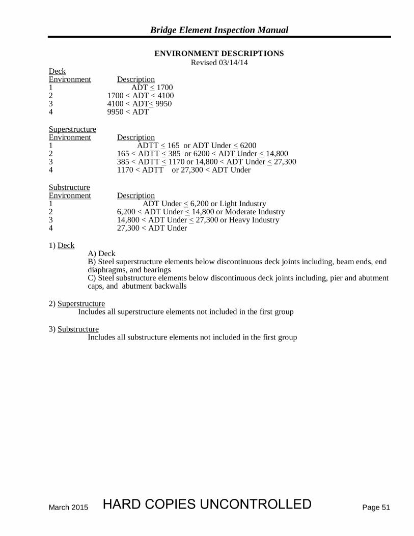
Bridge Element Inspection Manual
March 2015 Page 51
ENVIRONMENT DESCRIPTIONS Revised 03/14/14
Deck Environment Description 1 ADT < 1700 2 1700 < ADT < 4100 3 4100 < ADT< 9950 4 9950 < ADT Superstructure Environment Description 1 ADTT < 165 or ADT Under < 6200 2 165 < ADTT < 385 or 6200 < ADT Under < 14,800 3 385 < ADTT < 1170 or 14,800 < ADT Under < 27,300 4 1170 < ADTT or 27,300 < ADT Under Substructure Environment Description 1 ADT Under < 6,200 or Light Industry 2 6,200 < ADT Under < 14,800 or Moderate Industry 3 14,800 < ADT Under < 27,300 or Heavy Industry 4 27,300 < ADT Under 1) Deck
A) Deck B) Steel superstructure elements below discontinuous deck joints including, beam ends, end
diaphragms, and bearings C) Steel substructure elements below discontinuous deck joints including, pier and abutment
caps, and abutment backwalls 2) Superstructure
Includes all superstructure elements not included in the first group 3) Substructure
Includes all substructure elements not included in the first group
HARD COPIES UNCONTROLLED
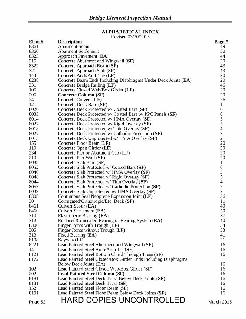
Bridge Element Inspection Manual
Page 52 March 2015
ALPHABETICAL INDEX Revised 03/20/2015
Elem # Description Page # 8361 Abutment Scour 49 8360 Abutment Settlement 50 8323 Approach Pavement (EA) 44 215 Concrete Abutment and Wingwall (SF) 20 8322 Concrete Approach Beam (SF) 43 321 Concrete Approach Slab (SF) 43 144 Concrete Arch/Arch Tie (LF) 20 8238 Concrete Beam Ends Including Diaphragms Under Deck Joints (EA) 20 331 Concrete Bridge Railing (LF) 46 105 Concrete Closed Web/Box Girder (LF) 20 205 Concrete Column (SF) 20 241 Concrete Culvert (LF) 26 12 Concrete Deck Bare (SF) 1 8026 Concrete Deck Protected w/ Coated Bars (SF) 6 8033 Concrete Deck Protected w/ Coated Bars w/ PPC Panels (SF) 6 8014 Concrete Deck Protected w/ HMA Overlay (SF) 3 8022 Concrete Deck Protected w/ Rigid Overlay (SF) 5 8018 Concrete Deck Protected w/ Thin Overlay (SF) 4 8027 Concrete Deck Protected w/ Cathodic Protection (SF) 7 8013 Concrete Deck Unprotected w/ HMA Overlay (SF) 2 155 Concrete Floor Beam (LF) 20 110 Concrete Open Girder (LF) 20 234 Concrete Pier or Abutment Cap (LF) 20 210 Concrete Pier Wall (SF) 20 8038 Concrete Slab Bare (SF) 1 8052 Concrete Slab Protected w/ Coated Bars (SF) 6 8040 Concrete Slab Protected w/ HMA Overlay (SF) 3 8048 Concrete Slab Protected w/ Rigid Overlay (SF) 5 8044 Concrete Slab Protected w/ Thin Overlay (SF) 4 8053 Concrete Slab Protected w/ Cathodic Protection (SF) 7 8039 Concrete Slab Unprotected w/ HMA Overlay (SF) 2 8308 Continuous Seal Neoprene Expansion Joint (LF) 36 30 Corrugated/Orthotropic/Etc. Deck (SF) 11 8461 Culvert Scour (EA) 49 8460 Culvert Settlement (EA) 50 310 Elastomeric Bearing (EA) 37 312 Enclosed/Concealed Bearing or Bearing System (EA) 40 8306 Finger Joints with Trough (LF) 34 305 Finger Joints without Trough (LF) 33 313 Fixed Bearing (EA) 41 8108 Keyway (LF) 21 8221 Lead Painted Steel Abutment and Wingwall (SF) 16 141 Lead Painted Steel Arch/Arch Tie (SF) 16 8121 Lead Painted Steel Bottom Chord Through Truss (SF) 16 8172 Lead Painted Steel Closed/Box Girder Ends Including Diaphragms Below Deck Joints (EA) 16 102 Lead Painted Steel Closed Web/Box Girder (SF) 16 202 Lead Painted Steel Column (SF) 16 8181 Lead Painted Steel Deck Truss Below Deck Joints (SF) 16 8131 Lead Painted Steel Deck Truss (SF) 16 152 Lead Painted Steel Floor Beam (SF) 16 8191 Lead Painted Steel Floor Beam Below Deck Joints (SF) 16
HARD COPIES UNCONTROLLED
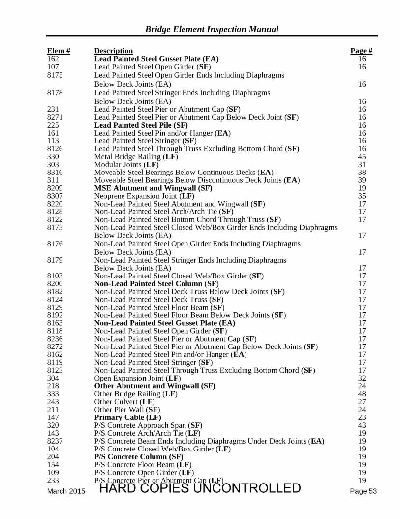
Bridge Element Inspection Manual
March 2015 Page 53
Elem # Description Page # 162 Lead Painted Steel Gusset Plate (EA) 16 107 Lead Painted Steel Open Girder (SF) 16 8175 Lead Painted Steel Open Girder Ends Including Diaphragms
Below Deck Joints (EA) 16 8178 Lead Painted Steel Stringer Ends Including Diaphragms
Below Deck Joints (EA) 16 231 Lead Painted Steel Pier or Abutment Cap (SF) 16 8271 Lead Painted Steel Pier or Abutment Cap Below Deck Joint (SF) 16 225 Lead Painted Steel Pile (SF) 16 161 Lead Painted Steel Pin and/or Hanger (EA) 16 113 Lead Painted Steel Stringer (SF) 16 8126 Lead Painted Steel Through Truss Excluding Bottom Chord (SF) 16 330 Metal Bridge Railing (LF) 45 303 Modular Joints (LF) 31 8316 Moveable Steel Bearings Below Continuous Decks (EA) 38 311 Moveable Steel Bearings Below Discontinuous Deck Joints (EA) 39 8209 MSE Abutment and Wingwall (SF) 19 8307 Neoprene Expansion Joint (LF) 35 8220 Non-Lead Painted Steel Abutment and Wingwall (SF) 17 8128 Non-Lead Painted Steel Arch/Arch Tie (SF) 17 8122 Non-Lead Painted Steel Bottom Chord Through Truss (SF) 17 8173 Non-Lead Painted Steel Closed Web/Box Girder Ends Including Diaphragms
Below Deck Joints (EA) 17 8176 Non-Lead Painted Steel Open Girder Ends Including Diaphragms
Below Deck Joints (EA) 17 8179 Non-Lead Painted Steel Stringer Ends Including Diaphragms
Below Deck Joints (EA) 17 8103 Non-Lead Painted Steel Closed Web/Box Girder (SF) 17 8200 Non-Lead Painted Steel Column (SF) 17 8182 Non-Lead Painted Steel Deck Truss Below Deck Joints (SF) 17 8124 Non-Lead Painted Steel Deck Truss (SF) 17 8129 Non-Lead Painted Steel Floor Beam (SF) 17 8192 Non-Lead Painted Steel Floor Beam Below Deck Joints (SF) 17 8163 Non-Lead Painted Steel Gusset Plate (EA) 17 8118 Non-Lead Painted Steel Open Girder (SF) 17 8236 Non-Lead Painted Steel Pier or Abutment Cap (SF) 17 8272 Non-Lead Painted Steel Pier or Abutment Cap Below Deck Joints (SF) 17 8162 Non-Lead Painted Steel Pin and/or Hanger (EA) 17 8119 Non-Lead Painted Steel Stringer (SF) 17 8123 Non-Lead Painted Steel Through Truss Excluding Bottom Chord (SF) 17 304 Open Expansion Joint (LF) 32 218 Other Abutment and Wingwall (SF) 24 333 Other Bridge Railing (LF) 48 243 Other Culvert (LF) 27 211 Other Pier Wall (SF) 24 147 Primary Cable (LF) 23 320 P/S Concrete Approach Span (SF) 43 143 P/S Concrete Arch/Arch Tie (LF) 19 8237 P/S Concrete Beam Ends Including Diaphragms Under Deck Joints (EA) 19 104 P/S Concrete Closed Web/Box Girder (LF) 19 204 P/S Concrete Column (SF) 19 154 P/S Concrete Floor Beam (LF) 19 109 P/S Concrete Open Girder (LF) 19 233 P/S Concrete Pier or Abutment Cap (LF) 19
HARD COPIES UNCONTROLLED
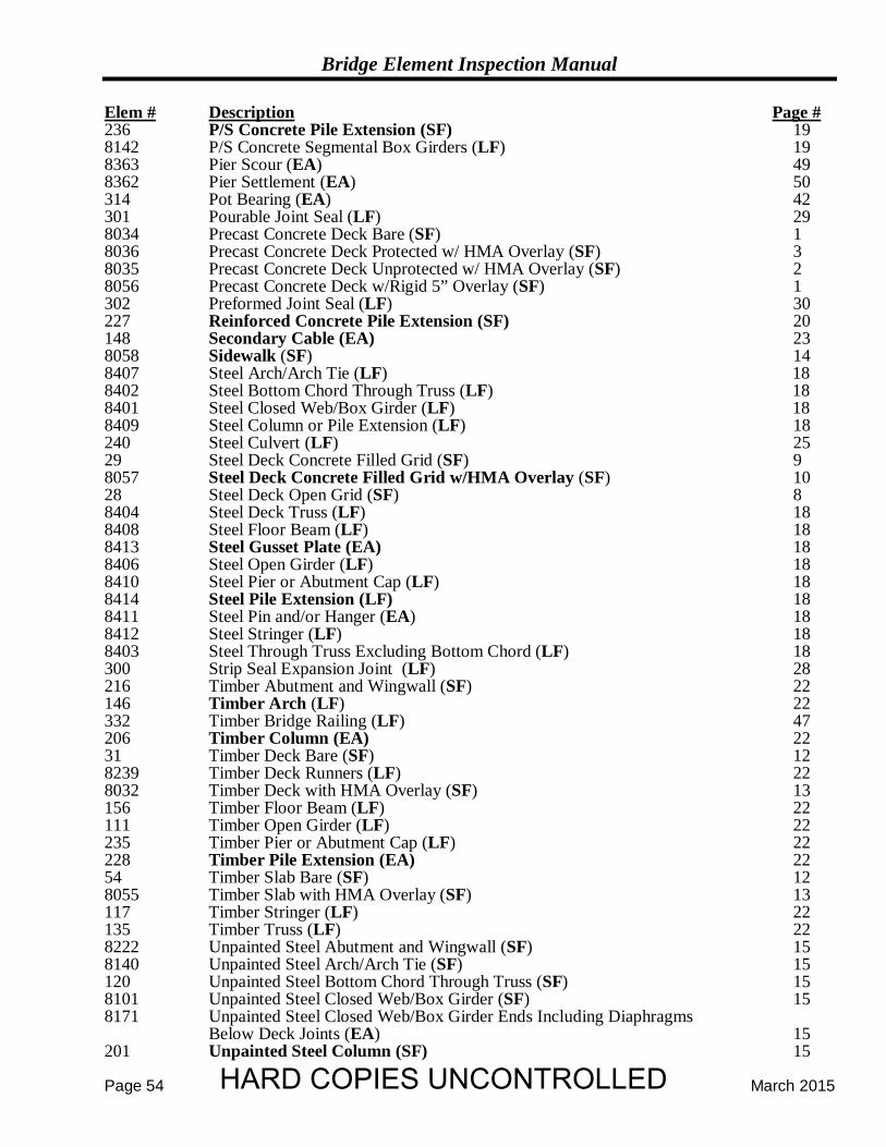
Bridge Element Inspection Manual
Page 54 March 2015
Elem # Description Page # 236 P/S Concrete Pile Extension (SF) 19 8142 P/S Concrete Segmental Box Girders (LF) 19 8363 Pier Scour (EA) 49 8362 Pier Settlement (EA) 50 314 Pot Bearing (EA) 42 301 Pourable Joint Seal (LF) 29 8034 Precast Concrete Deck Bare (SF) 1 8036 Precast Concrete Deck Protected w/ HMA Overlay (SF) 3 8035 Precast Concrete Deck Unprotected w/ HMA Overlay (SF) 2 8056 Precast Concrete Deck w/Rigid 5” Overlay (SF) 1 302 Preformed Joint Seal (LF) 30 227 Reinforced Concrete Pile Extension (SF) 20 148 Secondary Cable (EA) 23 8058 Sidewalk (SF) 14 8407 Steel Arch/Arch Tie (LF) 18 8402 Steel Bottom Chord Through Truss (LF) 18 8401 Steel Closed Web/Box Girder (LF) 18 8409 Steel Column or Pile Extension (LF) 18 240 Steel Culvert (LF) 25 29 Steel Deck Concrete Filled Grid (SF) 9 8057 Steel Deck Concrete Filled Grid w/HMA Overlay (SF) 10 28 Steel Deck Open Grid (SF) 8 8404 Steel Deck Truss (LF) 18 8408 Steel Floor Beam (LF) 18 8413 Steel Gusset Plate (EA) 18 8406 Steel Open Girder (LF) 18 8410 Steel Pier or Abutment Cap (LF) 18 8414 Steel Pile Extension (LF) 18 8411 Steel Pin and/or Hanger (EA) 18 8412 Steel Stringer (LF) 18 8403 Steel Through Truss Excluding Bottom Chord (LF) 18 300 Strip Seal Expansion Joint (LF) 28 216 Timber Abutment and Wingwall (SF) 22 146 Timber Arch (LF) 22 332 Timber Bridge Railing (LF) 47 206 Timber Column (EA) 22 31 Timber Deck Bare (SF) 12 8239 Timber Deck Runners (LF) 22 8032 Timber Deck with HMA Overlay (SF) 13 156 Timber Floor Beam (LF) 22 111 Timber Open Girder (LF) 22 235 Timber Pier or Abutment Cap (LF) 22 228 Timber Pile Extension (EA) 22 54 Timber Slab Bare (SF) 12 8055 Timber Slab with HMA Overlay (SF) 13 117 Timber Stringer (LF) 22 135 Timber Truss (LF) 22 8222 Unpainted Steel Abutment and Wingwall (SF) 15 8140 Unpainted Steel Arch/Arch Tie (SF) 15 120 Unpainted Steel Bottom Chord Through Truss (SF) 15 8101 Unpainted Steel Closed Web/Box Girder (SF) 15 8171 Unpainted Steel Closed Web/Box Girder Ends Including Diaphragms Below Deck Joints (EA) 15 201 Unpainted Steel Column (SF) 15
HARD COPIES UNCONTROLLED
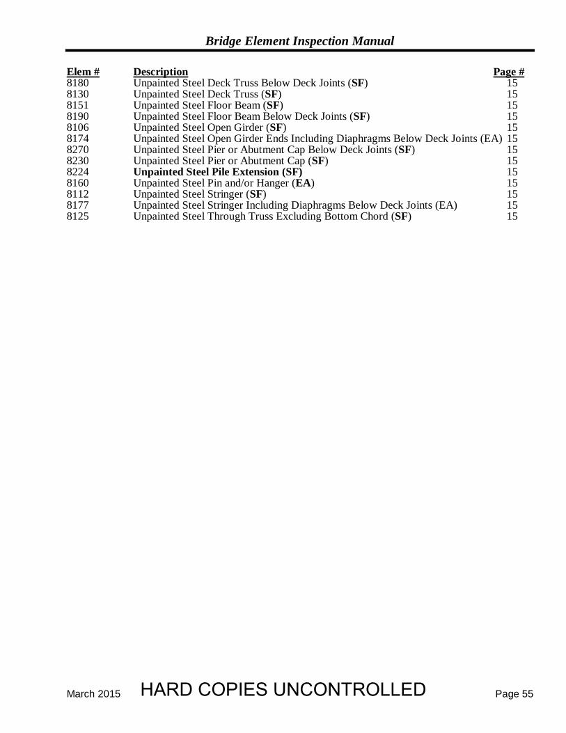
Bridge Element Inspection Manual
March 2015 Page 55
Elem # Description Page # 8180 Unpainted Steel Deck Truss Below Deck Joints (SF) 15 8130 Unpainted Steel Deck Truss (SF) 15 8151 Unpainted Steel Floor Beam (SF) 15 8190 Unpainted Steel Floor Beam Below Deck Joints (SF) 15 8106 Unpainted Steel Open Girder (SF) 15 8174 Unpainted Steel Open Girder Ends Including Diaphragms Below Deck Joints (EA) 15 8270 Unpainted Steel Pier or Abutment Cap Below Deck Joints (SF) 15 8230 Unpainted Steel Pier or Abutment Cap (SF) 15 8224 Unpainted Steel Pile Extension (SF) 15 8160 Unpainted Steel Pin and/or Hanger (EA) 15 8112 Unpainted Steel Stringer (SF) 15 8177 Unpainted Steel Stringer Including Diaphragms Below Deck Joints (EA) 15 8125 Unpainted Steel Through Truss Excluding Bottom Chord (SF) 15
HARD COPIES UNCONTROLLED
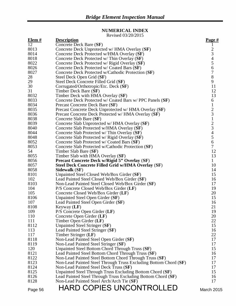
Bridge Element Inspection Manual
Page 56 March 2015
NUMERICAL INDEX Revised 03/20/2015
Elem # Description Page # 12 Concrete Deck Bare (SF) 1 8013 Concrete Deck Unprotected w/ HMA Overlay (SF) 2 8014 Concrete Deck Protected w/HMA Overlay (SF) 3 8018 Concrete Deck Protected w/ Thin Overlay (SF) 4 8022 Concrete Deck Protected w/ Rigid Overlay (SF) 5 8026 Concrete Deck Protected w/ Coated Bars (SF) 6 8027 Concrete Deck Protected w/Cathodic Protection (SF) 7 28 Steel Deck Open Grid (SF) 8 29 Steel Deck Concrete Filled Grid (SF) 9 30 Corrugated/Orthotropic/Etc. Deck (SF) 11 31 Timber Deck Bare (SF) 12 8032 Timber Deck with HMA Overlay (SF) 13 8033 Concrete Deck Protected w/ Coated Bars w/ PPC Panels (SF) 6 8034 Precast Concrete Deck Bare (SF) 1 8035 Precast Concrete Deck Unprotected w/ HMA Overlay (SF) 2 8036 Precast Concrete Deck Protected w/ HMA Overlay (SF) 3 8038 Concrete Slab Bare (SF) 1 8039 Concrete Slab Unprotected w/ HMA Overlay (SF) 2 8040 Concrete Slab Protected w/HMA Overlay (SF) 3 8044 Concrete Slab Protected w/ Thin Overlay (SF) 4 8048 Concrete Slab Protected w/ Rigid Overlay (SF) 5 8052 Concrete Slab Protected w/ Coated Bars (SF) 6 8053 Concrete Slab Protected w/Cathodic Protection (SF) 7 54 Timber Slab Bare (SF) 12 8055 Timber Slab with HMA Overlay (SF) 13 8056 Precast Concrete Deck w/Rigid 5” Overlay (SF) 1 8057 Steel Deck Concrete Filled Grid w/HMA Overlay (SF) 10 8058 Sidewalk (SF) 14 8101 Unpainted Steel Closed Web/Box Girder (SF) 15 102 Lead Painted Steel Closed Web/Box Girder (SF) 16 8103 Non-Lead Painted Steel Closed Web/Box Girder (SF) 17 104 P/S Concrete Closed Web/Box Girder (LF) 19 105 Concrete Closed Web/Box Girder (LF) 20 8106 Unpainted Steel Open Girder (SF) 15 107 Lead Painted Steel Open Girder (SF) 16 8108 Keyway (LF) 21 109 P/S Concrete Open Girder (LF) 19 110 Concrete Open Girder (LF) 20 111 Timber Open Girder (LF) 22 8112 Unpainted Steel Stringer (SF) 15 113 Lead Painted Steel Stringer (SF) 16 117 Timber Stringer (LF) 22 8118 Non-Lead Painted Steel Open Girder (SF) 17 8119 Non-Lead Painted Steel Stringer (SF) 17 120 Unpainted Steel Bottom Chord Through Truss (SF) 15 8121 Lead Painted Steel Bottom Chord Through Truss (SF) 16 8122 Non-Lead Painted Steel Bottom Chord Through Truss (SF) 17 8123 Non-Lead Painted Steel Through Truss Excluding Bottom Chord (SF) 17 8124 Non-Lead Painted Steel Deck Truss (SF) 17 8125 Unpainted Steel Through Truss Excluding Bottom Chord (SF) 15 8126 Lead Painted Steel Through Truss Excluding Bottom Chord (SF) 16 8128 Non-Lead Painted Steel Arch/Arch Tie (SF) 17
HARD COPIES UNCONTROLLED
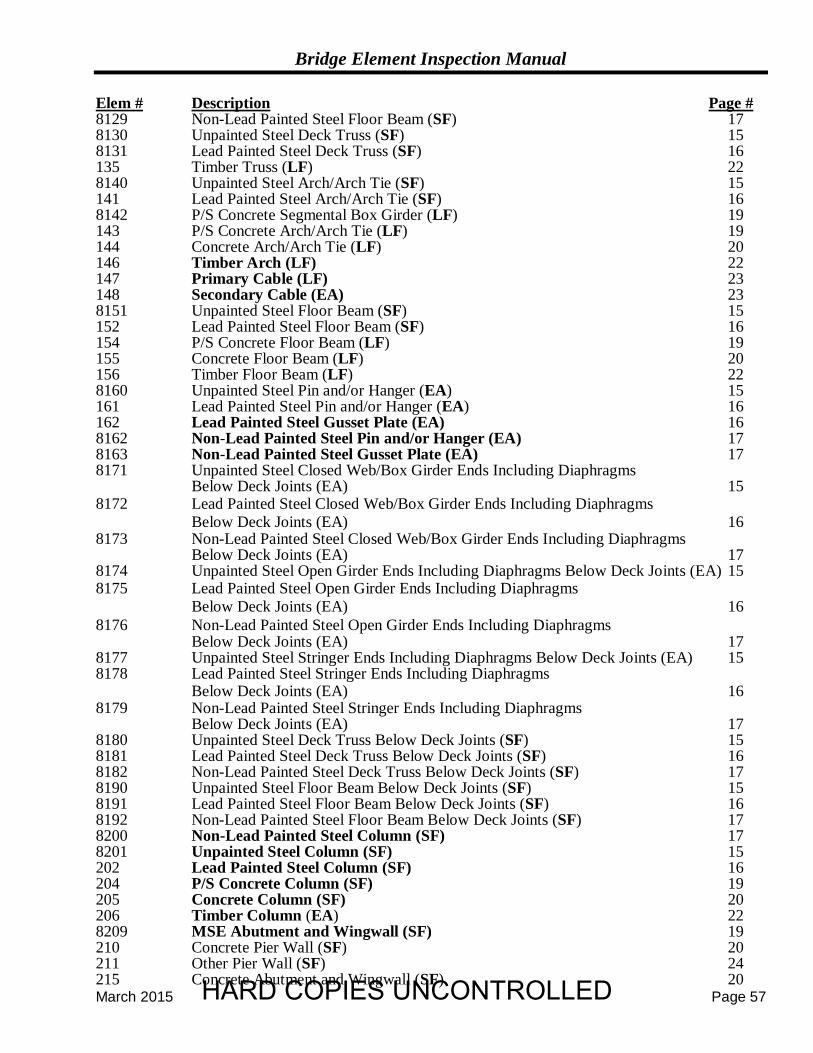
Bridge Element Inspection Manual
March 2015 Page 57
Elem # Description Page # 8129 Non-Lead Painted Steel Floor Beam (SF) 17 8130 Unpainted Steel Deck Truss (SF) 15 8131 Lead Painted Steel Deck Truss (SF) 16 135 Timber Truss (LF) 22 8140 Unpainted Steel Arch/Arch Tie (SF) 15 141 Lead Painted Steel Arch/Arch Tie (SF) 16 8142 P/S Concrete Segmental Box Girder (LF) 19 143 P/S Concrete Arch/Arch Tie (LF) 19 144 Concrete Arch/Arch Tie (LF) 20 146 Timber Arch (LF) 22 147 Primary Cable (LF) 23 148 Secondary Cable (EA) 23 8151 Unpainted Steel Floor Beam (SF) 15 152 Lead Painted Steel Floor Beam (SF) 16 154 P/S Concrete Floor Beam (LF) 19 155 Concrete Floor Beam (LF) 20 156 Timber Floor Beam (LF) 22 8160 Unpainted Steel Pin and/or Hanger (EA) 15 161 Lead Painted Steel Pin and/or Hanger (EA) 16 162 Lead Painted Steel Gusset Plate (EA) 16 8162 Non-Lead Painted Steel Pin and/or Hanger (EA) 17 8163 Non-Lead Painted Steel Gusset Plate (EA) 17 8171 Unpainted Steel Closed Web/Box Girder Ends Including Diaphragms Below Deck Joints (EA) 15 8172 Lead Painted Steel Closed Web/Box Girder Ends Including Diaphragms
Below Deck Joints (EA) 16 8173 Non-Lead Painted Steel Closed Web/Box Girder Ends Including Diaphragms
Below Deck Joints (EA) 17 8174 Unpainted Steel Open Girder Ends Including Diaphragms Below Deck Joints (EA) 15 8175 Lead Painted Steel Open Girder Ends Including Diaphragms
Below Deck Joints (EA) 16 8176 Non-Lead Painted Steel Open Girder Ends Including Diaphragms
Below Deck Joints (EA) 17 8177 Unpainted Steel Stringer Ends Including Diaphragms Below Deck Joints (EA) 15 8178 Lead Painted Steel Stringer Ends Including Diaphragms
Below Deck Joints (EA) 16 8179 Non-Lead Painted Steel Stringer Ends Including Diaphragms
Below Deck Joints (EA) 17 8180 Unpainted Steel Deck Truss Below Deck Joints (SF) 15 8181 Lead Painted Steel Deck Truss Below Deck Joints (SF) 16 8182 Non-Lead Painted Steel Deck Truss Below Deck Joints (SF) 17 8190 Unpainted Steel Floor Beam Below Deck Joints (SF) 15 8191 Lead Painted Steel Floor Beam Below Deck Joints (SF) 16 8192 Non-Lead Painted Steel Floor Beam Below Deck Joints (SF) 17 8200 Non-Lead Painted Steel Column (SF) 17 8201 Unpainted Steel Column (SF) 15 202 Lead Painted Steel Column (SF) 16 204 P/S Concrete Column (SF) 19 205 Concrete Column (SF) 20 206 Timber Column (EA) 22 8209 MSE Abutment and Wingwall (SF) 19 210 Concrete Pier Wall (SF) 20 211 Other Pier Wall (SF) 24 215 Concrete Abutment and Wingwall (SF) 20 HARD COPIES UNCONTROLLED
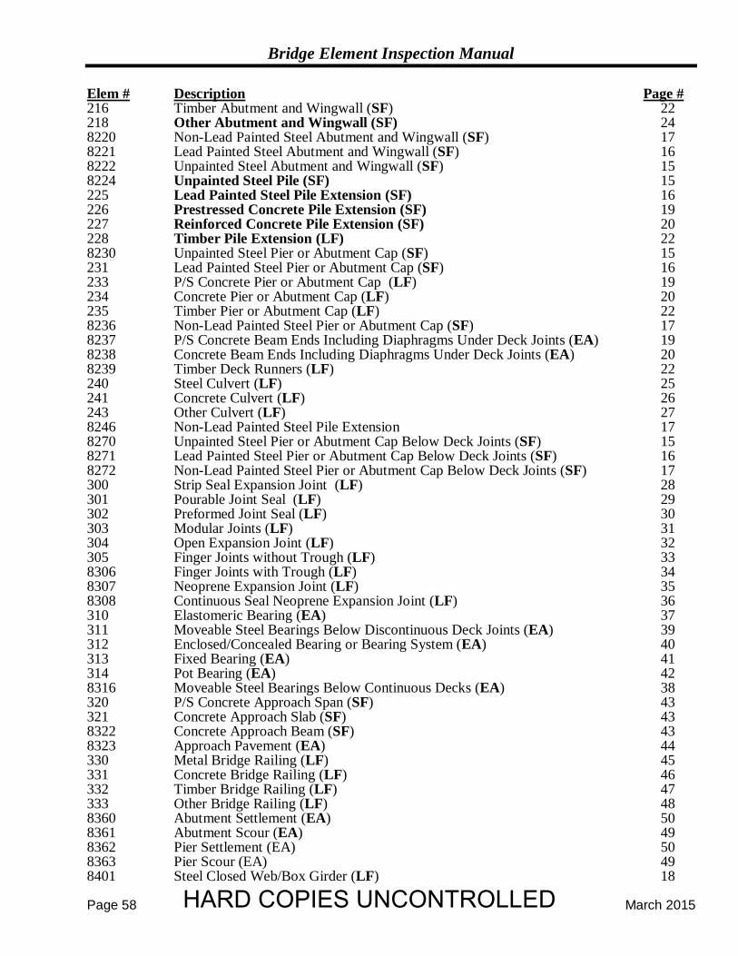
Bridge Element Inspection Manual
Page 58 March 2015
Elem # Description Page # 216 Timber Abutment and Wingwall (SF) 22 218 Other Abutment and Wingwall (SF) 24 8220 Non-Lead Painted Steel Abutment and Wingwall (SF) 17 8221 Lead Painted Steel Abutment and Wingwall (SF) 16 8222 Unpainted Steel Abutment and Wingwall (SF) 15 8224 Unpainted Steel Pile (SF) 15 225 Lead Painted Steel Pile Extension (SF) 16 226 Prestressed Concrete Pile Extension (SF) 19 227 Reinforced Concrete Pile Extension (SF) 20 228 Timber Pile Extension (LF) 22 8230 Unpainted Steel Pier or Abutment Cap (SF) 15 231 Lead Painted Steel Pier or Abutment Cap (SF) 16 233 P/S Concrete Pier or Abutment Cap (LF) 19 234 Concrete Pier or Abutment Cap (LF) 20 235 Timber Pier or Abutment Cap (LF) 22 8236 Non-Lead Painted Steel Pier or Abutment Cap (SF) 17 8237 P/S Concrete Beam Ends Including Diaphragms Under Deck Joints (EA) 19 8238 Concrete Beam Ends Including Diaphragms Under Deck Joints (EA) 20 8239 Timber Deck Runners (LF) 22 240 Steel Culvert (LF) 25 241 Concrete Culvert (LF) 26 243 Other Culvert (LF) 27 8246 Non-Lead Painted Steel Pile Extension 17 8270 Unpainted Steel Pier or Abutment Cap Below Deck Joints (SF) 15 8271 Lead Painted Steel Pier or Abutment Cap Below Deck Joints (SF) 16 8272 Non-Lead Painted Steel Pier or Abutment Cap Below Deck Joints (SF) 17 300 Strip Seal Expansion Joint (LF) 28 301 Pourable Joint Seal (LF) 29 302 Preformed Joint Seal (LF) 30 303 Modular Joints (LF) 31 304 Open Expansion Joint (LF) 32 305 Finger Joints without Trough (LF) 33 8306 Finger Joints with Trough (LF) 34 8307 Neoprene Expansion Joint (LF) 35 8308 Continuous Seal Neoprene Expansion Joint (LF) 36 310 Elastomeric Bearing (EA) 37 311 Moveable Steel Bearings Below Discontinuous Deck Joints (EA) 39 312 Enclosed/Concealed Bearing or Bearing System (EA) 40 313 Fixed Bearing (EA) 41 314 Pot Bearing (EA) 42 8316 Moveable Steel Bearings Below Continuous Decks (EA) 38 320 P/S Concrete Approach Span (SF) 43 321 Concrete Approach Slab (SF) 43 8322 Concrete Approach Beam (SF) 43 8323 Approach Pavement (EA) 44 330 Metal Bridge Railing (LF) 45 331 Concrete Bridge Railing (LF) 46 332 Timber Bridge Railing (LF) 47 333 Other Bridge Railing (LF) 48 8360 Abutment Settlement (EA) 50 8361 Abutment Scour (EA) 49 8362 Pier Settlement (EA) 50 8363 Pier Scour (EA) 49 8401 Steel Closed Web/Box Girder (LF) 18
HARD COPIES UNCONTROLLED
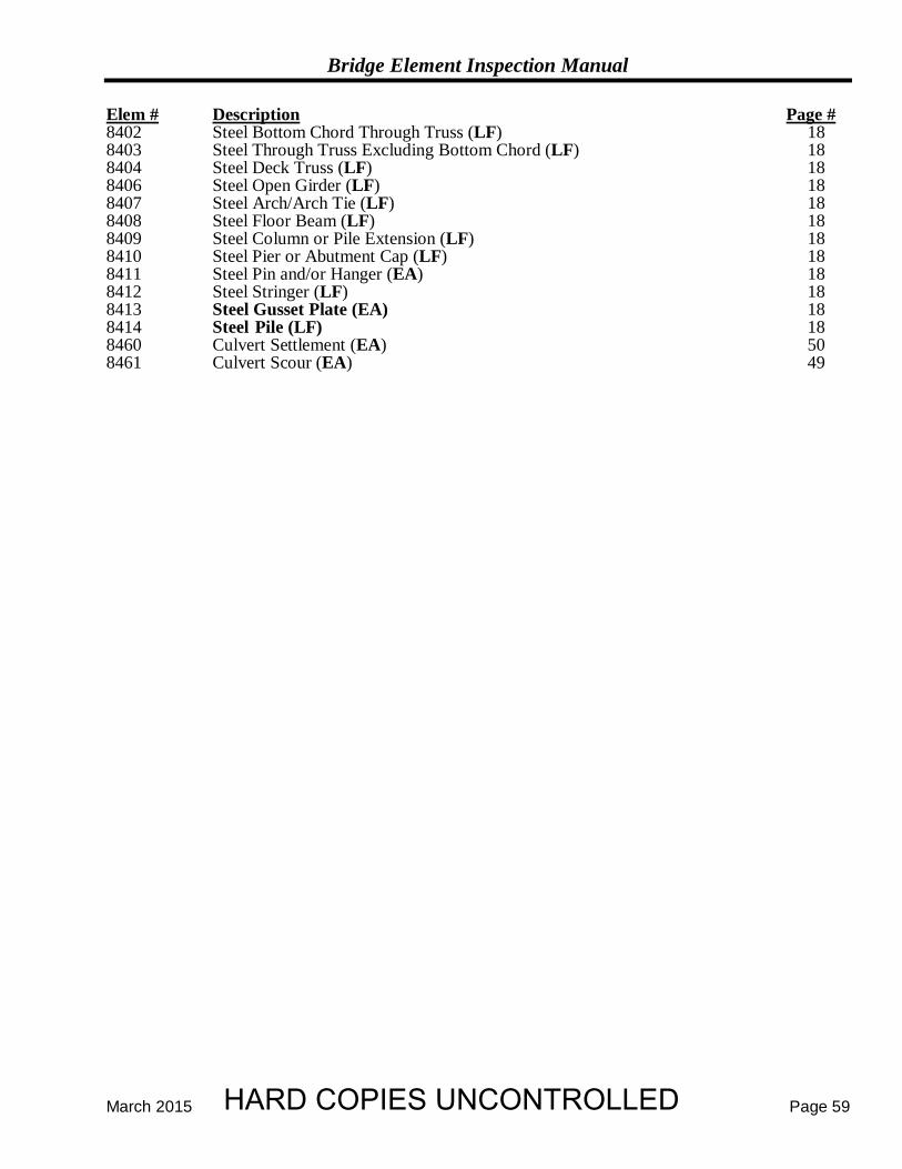
Bridge Element Inspection Manual
March 2015 Page 59
Elem # Description Page # 8402 Steel Bottom Chord Through Truss (LF) 18 8403 Steel Through Truss Excluding Bottom Chord (LF) 18 8404 Steel Deck Truss (LF) 18 8406 Steel Open Girder (LF) 18 8407 Steel Arch/Arch Tie (LF) 18 8408 Steel Floor Beam (LF) 18 8409 Steel Column or Pile Extension (LF) 18 8410 Steel Pier or Abutment Cap (LF) 18 8411 Steel Pin and/or Hanger (EA) 18 8412 Steel Stringer (LF) 18 8413 Steel Gusset Plate (EA) 18 8414 Steel Pile (LF) 18 8460 Culvert Settlement (EA) 50 8461 Culvert Scour (EA) 49
HARD COPIES UNCONTROLLED

Appendix
HARD COPIES UNCONTROLLED
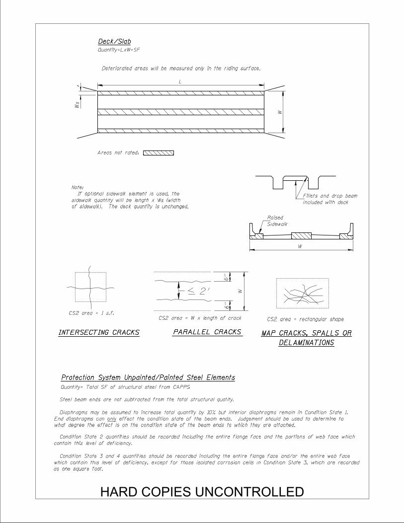
Deteriorated areas will be measured only in the riding surface.
L
W
Deck/Slab
Quantity=LxW=SF
W
Areas not rated:
Protection System Unpainted/Painted Steel Elements
Sidewalk
Raised
Quantity= Total SF of structural steel from CAPPS
included with deck
Fillets and drop beam
Steel beam ends are not subtracted from the total structural quatity.
INTERSECTING CRACKS
W
6’’
6’’
2’
PARALLEL CRACKS
DELAMINATIONS
MAP CRACKS, SPALLS OR
Diaphragms may be assumed to increase total quantity by 10% but interior diaphragms remain in Condition State 1.
End diaphragms can only effect the condition state of the beam ends. Judgement should be used to determine to
what degree the effect is on the condition state of the beam ends to which they are attached.
contain this level of deficiency.
as one square foot.
of sidewalk). The deck quantity is unchanged.
sidewalk quantity will be length x W (width
If optional sidewalk element is used, the
Note:
s
Ws
Condition State 2 quantities should be recorded including the entire flange face and the portions of web face which
Condition State 3 and 4 quantities should be recorded including the entire flange face and/or the entire web face
which contain this level of deficiency, except for those isolated corrosion cells in Condition State 3, which are recorded
CS2 area = 1 s.f.
CS2 area = W x length of crack CS2 area = rectangular shape
HARD COPIES UNCONTROLLED
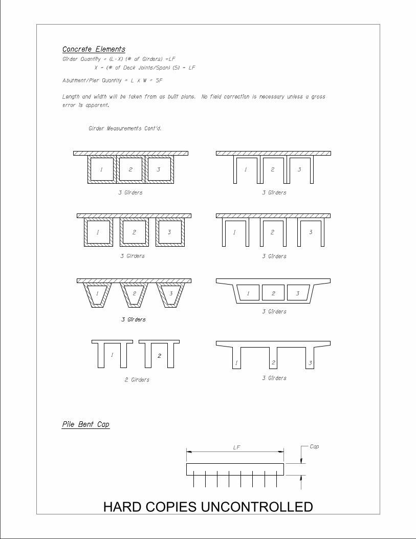
Concrete Elements
X = (# of Deck Joints/Span) (5) = LF
Girder Quantity = (L-X) (# of Girders) =LF
Abutment/Pier Quantity = L x W = SF
error is apparent.
Length and width will be taken from as built plans. No field correction is necessary unless a gross
Girder Measurements Cont’d.
1 2 3
1 2 3
1 2 3
1 22
3 Girders
3 Girders
3 Girders3 Girders
2 Girders
3 Girders
3 Girders
3 Girders
3 Girders
1
1
1
1
2 3
2 3
2 3
2 3
LF
Pile Bent Cap
Cap
HARD COPIES UNCONTROLLED
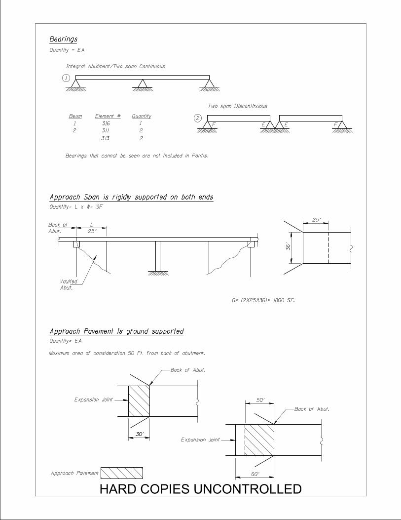
L
25’
Bearings
Quantity = EA
1
Integral Abutment/Two span Continuous
Beam
1
2
Element #
316
311
Quantity
1
2
2
Two span Discontinuous
Quantity= L x W= SF
Abut.
Back of
Abut.
Vaulted
36’
25’
Q= (2)(25)(36)= 1800 SF.
Quantity= EA
Maximum area of consideration 50 Ft. from back of abutment.
Back of Abut.
Expansion Joint
Back of Abut.
Expansion Joint
30’30’
60’
50’
Approach Pavement
Bearings that cannot be seen are not included in Pontis.
313 2
Approach Span is rigidly supported on both ends
F FE E
Approach Pavement is ground supported
HARD COPIES UNCONTROLLED

Timber Elements
Quantity = L x (# of Girders) = LF
11 2 3 4 5 6 7 8
9
10
Culverts
Quantity = L x (# of Barrels) = LF
Two Barrels => 7.51 Ft
One Barrel = 5 Ft - 7.5 Ft
24’
6’
6’
6’
24’
12’
Four Barrels Four Barrels
Joints
Quantity = LF
36’
Q = (36)/Sin 60° = 41.6’
60°
Top View
Measurements taken along joint.
categories on page 49.
loads (no fill). When direct traffic loads are received the environment is determined from the worst of the three
Culvert environments are determined using subtructures criteria except when the top slab receives direct traffic
Secondary Cable
Quantity = EA Quantity = LF
Primary Cable
1000’
Total Quantity= (2) * (8) = 16EA Total Quantity= (2) * (1000’) = 2000 LF
(measured along length of cable)
HARD COPIES UNCONTROLLED
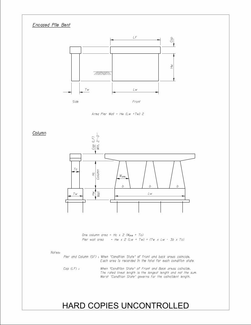
Encased Pile Bent
LF
LwTw
Hw
Side Front
Area Pier Wall = Hw (Lw +Tw) 2
Column
Tc
Tw Hw
Wall
Hc
Colu
mn
Cap (L
F)
Min.
2’-
0’’
Wave
b b b
Lw
One column area = Hc x 2 (W + Tc)ave
Notes:
Pier wall area = Hw x 2 (Lw + Tw) + (Tw x Lw - 3b x Tc)
Pier and Column (SF) : When "Condition State" of front and back areas coincide.
Each area is recorded in the total for each condition state.
Cap (LF) : When "Condition State" of Front and Back areas coincide.
The rated lineal length is the longest length and not the sum.
Worst "Condition State" governs for the coincident length.
Cap
HARD COPIES UNCONTROLLED
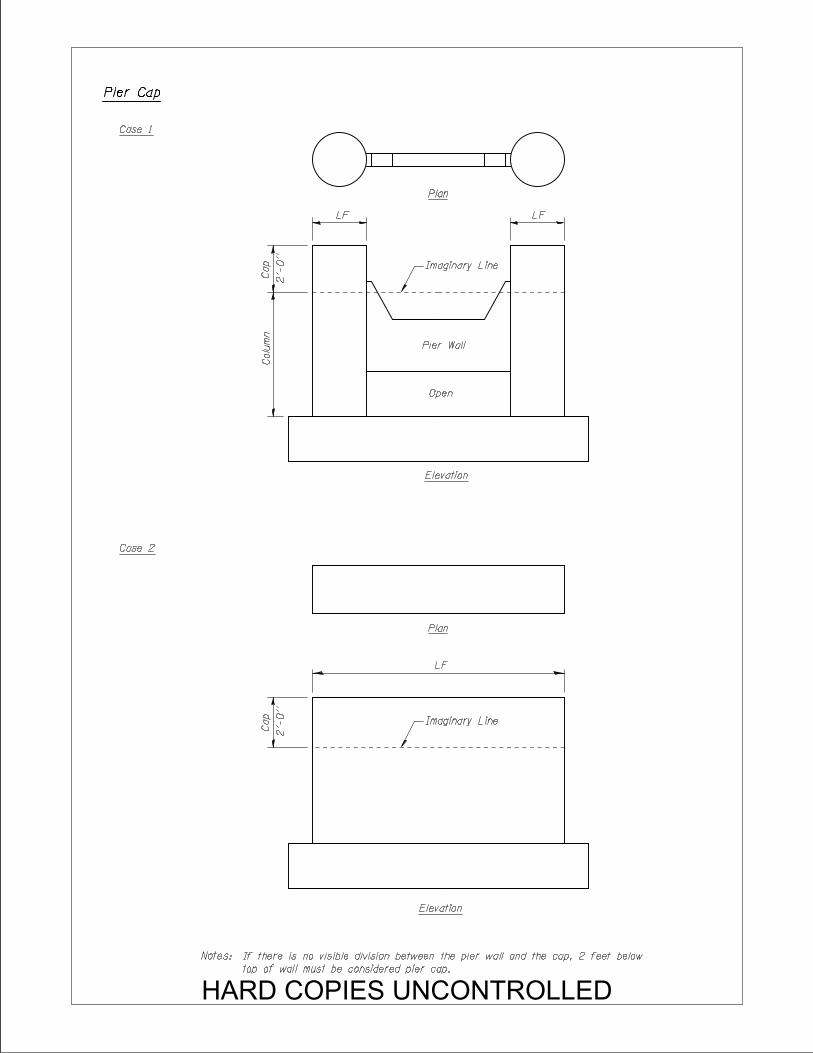
LF LF
Plan
Colu
mn
Cap
2’-
0’’
Imaginary Line
Pier Wall
Open
Elevation
Pier Cap
Case 1
Case 2
Elevation
LF
Plan
Imaginary Line
Notes:
top of wall must be considered pier cap.
Cap
2’-
0’’
If there is no visible division between the pier wall and the cap, 2 feet below
HARD COPIES UNCONTROLLED
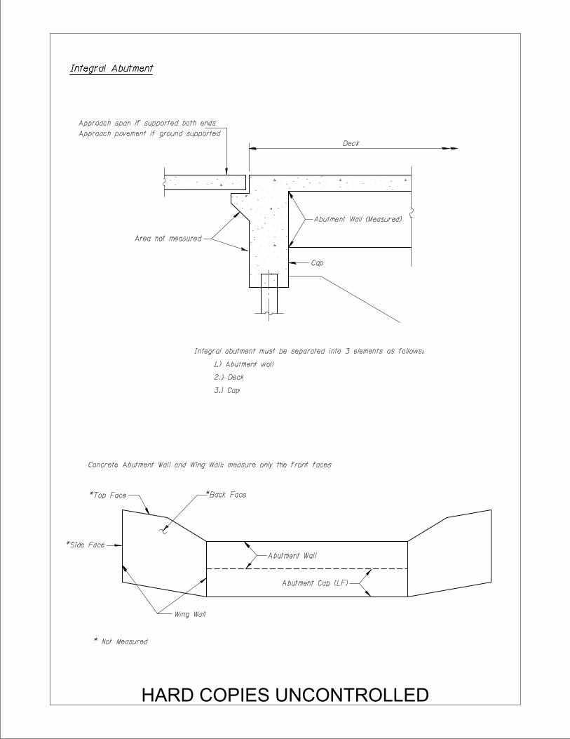
Deck
Cap
Integral Abutment
Approach span if supported both ends
Approach pavement if ground supported
3.) Cap
2.) Deck
1.) Abutment wall
Integral abutment must be separated into 3 elements as follows:
Abutment Wall (Measured)
Area not measured
*Back Face*Top Face
*Side Face
Wing Wall
Abutment Wall
Abutment Cap (LF)
Concrete Abutment Wall and Wing Wall: measure only the front faces
* Not Measured
HARD COPIES UNCONTROLLED
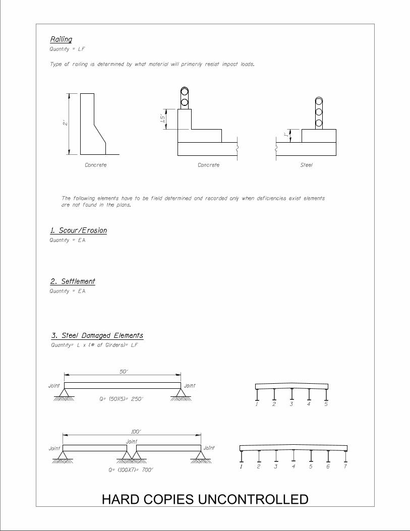
Quantity= L x (# of Girders)= LF
50’
Joint Joint
100’
Joint
Joint
Joint
2’
Concrete1.5’
1’
Concrete Steel
Quantity = LF
Railing
Type of railing is determined by what material will primarily resist impact loads.
Quantity = EA
Quantity = EA
1 2 3 4 5
11 2 3 4 5 6 7
Q= (50)(5)= 250’
Q= (100)(7)= 700’
are not found in the plans.
The following elements have to be field determined and recorded only when deficiencies exist elements
1. Scour/Erosion
2. Settlement
3. Steel Damaged Elements
HARD COPIES UNCONTROLLED
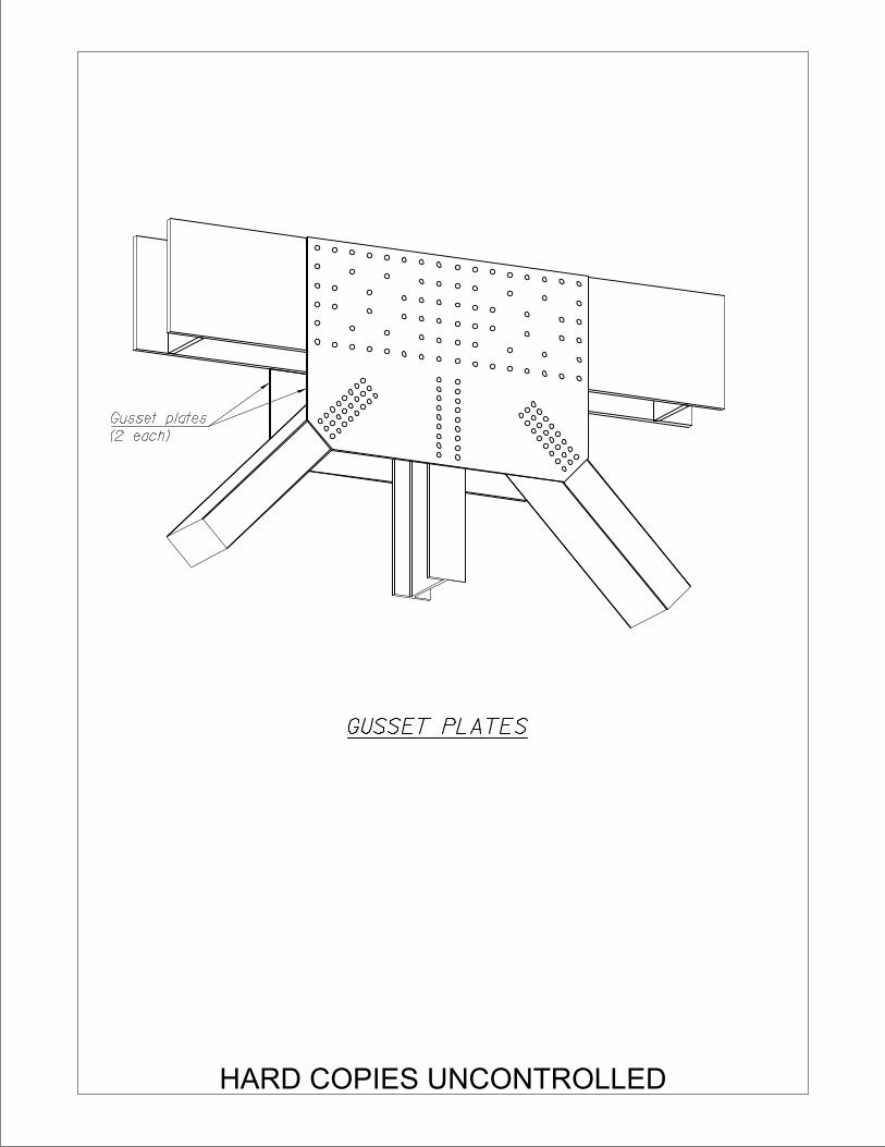
(2 each)
Gusset plates
GUSSET PLATES
HARD COPIES UNCONTROLLED