Michigan Bridge Element Inspection Manual · The purpose of the Michigan Bridge Element Inspection...
79
MICHIGAN BRIDGE ELEMENT INSPECTION MANUAL 10/24/2017
Transcript of Michigan Bridge Element Inspection Manual · The purpose of the Michigan Bridge Element Inspection...
MICHIGAN BRIDGE ELEMENT INSPECTION MANUAL
10/24/2017
Michigan Bridge Element Inspection Manual
Revised 10/24/2017 Page 1
Engineering Manual Preamble
This manual provides guidance to administrative, engineering, and technical staff. Engineering practice requires that professionals use a
combination of technical skills and judgment in decision making. Engineering judgment is necessary to allow decisions to account for
unique site-specific conditions and considerations to provide high quality products, within budget, and to protect the public health, safety,
and welfare. This manual provides the general operational guidelines; however, it is understood that adaptation, adjustments, and
deviations are sometimes necessary. Innovation is a key foundational element to advance the state of engineering practice and develop
more effective and efficient engineering solutions and materials. As such, it is essential that our engineering manuals provide a vehicle to
promote, pilot, or implement technologies or practices that provide efficiencies and quality products, while maintaining the safety, health,
and welfare of the public. It is expected when making significant or impactful deviations from the technical information from these
guidance materials, that reasonable consultations with experts, technical committees, and/or policy setting bodies occur prior to actions
within the timeframes allowed. It is also expected that these consultations will eliminate any potential conflicts of interest, perceived or
otherwise. MDOT Leadership is committed to a culture of innovation to optimize engineering solutions.
The National Society of Professional Engineers Code of Ethics for Engineering is founded on six fundamental canons. Those canons are
provided below.
Engineers, in the fulfillment of their professional duties, shall: 1. Hold paramount the safety, health, and welfare of the public. 2. Perform Services only in areas of their competence. 3. Issue public statement only in an objective and truthful manner. 4. Act for each employer or client as faithful agents or trustees. 5. Avoid deceptive acts. 6. Conduct themselves honorably, reasonably, ethically and lawfully so as to enhance the honor, reputation, and usefulness of the
profession.
Michigan Bridge Element Inspection Manual
Revised 10/24/2017 Page 2
INTRODUCTION
The purpose of the Michigan Bridge Element Inspection Manual (MiBEIM) is to provide condition state information for structures inspected within the state of Michigan. These structures typically include highway bridges and culverts with span lengths 10’ or greater. This manual is to be used by bridge owners and inspectors when collecting element level data. This manual supplements the AASHTO Manual for Bridge Element Inspection and provides further classification of the AASHTO elements and descriptions for Agency Developed Elements. The most effective tool for proper bridge management is the consistent condition assessment of bridge elements. The element level inspection method breaks the bridge down into several elements, such as the railing, deck, girders, abutments, pier columns, etc. Each element is inspected and assigned a Condition State based on the amount of deterioration. The element level inspection is a quantity based inspection and each quantity is assigned a Condition State to reflect the differing categories of deterioration that often exist on any bridge element.
One of the end results of performing element level inspections is the generation of a database for a bridge management system. By developing a database over time, bridge deterioration rates based upon material, geographic location, age, usage, type of crossing, prior rehabilitation or preventive actions, etc. can be estimated. The software modeling capabilities allows comparisons between the effectiveness of preventive and corrective actions, predictions of estimated future deterioration, and life cycle costs. Decisions can be made regarding prioritizing funds, when (or when not) to take action, and what type of action to take for the maximum benefit of capital spent.
Michigan Bridge Element Inspection Manual
Revised 10/24/2017 Page 3
Detailed Element Descriptions This manual describes the individual bridge elements evaluated in bridge inspection and management processes. The first section of the manual contains a detailed description for each element and is broken down into the following subsections:
Element Number and Name
Condition State Table to Reference
Description—Detailed identification and classification of the element.
Quantity Calculation—General guidelines on how to collect the quantity of the element and units.
Element Commentary—Additional considerations the inspector to be aware of during data collection, as appropriate. The condition state tables are in the second section of the manual. They contain the following information:
Condition State Definitions—Defect descriptions and severity with guidelines for the inspector on defect severity categorization.
Pictures – Example cases of condition states.
An appendix is included with the following information:
Clarification of the quantities of certain elements.
Summary of MDOT Agency Developed Elements All elements described are included in the standard set of National Bridge Elements (NBE), Bridge Management Elements (BME), or MDOT Agency Developed Elements (ADE). The elements are organized by major groupings such as Decks and Slabs, Superstructure, Bearings, Substructure, etc.
Michigan Bridge Element Inspection Manual
Revised 10/24/2017 Page 4
INDEX
DECKS/SLABS --------------------------------------------------------------------------------------------------------------------------- 7 DECK (sq. ft.) -------------------------------------------------------------------------------------------------------------------------------------- 8 SLAB (sq. ft.) ------------------------------------------------------------------------------------------------------------------------------------ 10 TOP FLANGE (sq. ft.) -------------------------------------------------------------------------------------------------------------------------- 11 DECK TOP SURFACE (sq. ft.) ----------------------------------------------------------------------------------------------------------------- 12 DECK BOTTOM SURFACE (sq. ft.) ---------------------------------------------------------------------------------------------------------- 12 FASCIA (ft.) -------------------------------------------------------------------------------------------------------------------------------------- 13 SIDEWALK (sq. ft.) ----------------------------------------------------------------------------------------------------------------------------- 14 PEDESTRIAN APPROACH (ea) --------------------------------------------------------------------------------------------------------------- 14 WEARING SURFACES (sq. ft.) --------------------------------------------------------------------------------------------------------------- 15 FALSE DECKING, MAINTENANCE SHEETING AND STAY-IN_PLACE FORMS (sq. ft.) -------------------------------------------- 16 JOINTS (ft.) -------------------------------------------------------------------------------------------------------------------------------------- 17
APPROACH SLAB (sq. ft.) -----------------------------------------------------------------------------------------------------------18
BRIDGE RAILING (ft.) ----------------------------------------------------------------------------------------------------------------19
SUPERSTRUCTURE -------------------------------------------------------------------------------------------------------------------20 GIRDERS (ft.) ------------------------------------------------------------------------------------------------------------------------------------ 21 FLOOR BEAMS (ft.) ---------------------------------------------------------------------------------------------------------------------------- 23 STRINGERS (ft.) --------------------------------------------------------------------------------------------------------------------------------- 24 TRUSSES (ft.) ------------------------------------------------------------------------------------------------------------------------------------ 25 ARCHES (ft.) ------------------------------------------------------------------------------------------------------------------------------------- 26 CABLES (See Description) -------------------------------------------------------------------------------------------------------------------- 27 MISCELLANEOUS SUPERSTRUCTURE ELEMENTS (ea.) -------------------------------------------------------------------------------- 28
Michigan Bridge Element Inspection Manual
Revised 10/24/2017 Page 5
INDEX (Continued) PROTECTIVE COATING (sq. ft.) ---------------------------------------------------------------------------------------------------30
BEARINGS (ea.) -----------------------------------------------------------------------------------------------------------------------32
SUBSTRUCTURE ----------------------------------------------------------------------------------------------------------------------33 ABUTMENT (ft.) -------------------------------------------------------------------------------------------------------------------------------- 34 WINGWALL (ea.) ------------------------------------------------------------------------------------------------------------------------------- 35 COLUMN (ea.) ---------------------------------------------------------------------------------------------------------------------------------- 36 PIER WALL (ft.) --------------------------------------------------------------------------------------------------------------------------------- 37 PIER CAP (ft.) ------------------------------------------------------------------------------------------------------------------------------------ 38 PILE (ea.) ----------------------------------------------------------------------------------------------------------------------------------------- 39 PILE CAP/FOOTING (ft.) ---------------------------------------------------------------------------------------------------------------------- 39 TOWER (ft.) ------------------------------------------------------------------------------------------------------------------------------------- 40 TRESTLE (ft.) ------------------------------------------------------------------------------------------------------------------------------------ 40
CULVERT --------------------------------------------------------------------------------------------------------------------------------41 CULVERT (ft.) ----------------------------------------------------------------------------------------------------------------------------------- 42
SCOUR PROTECTION ----------------------------------------------------------------------------------------------------------------43 SCOUR MONITORING (ea.) ------------------------------------------------------------------------------------------------------------------ 44
APPURTENANCES (ea.) -------------------------------------------------------------------------------------------------------------45
Michigan Bridge Element Inspection Manual
Revised 10/24/2017 Page 6
INDEX (Continued) CONDITION STATE TABLES --------------------------------------------------------------------------------------------------------48
CS TABLE 1 – REINFORCED CONCRETE --------------------------------------------------------------------------------------------------- 49 CS TABLE 2 – PRESTRESSED CONCRETE -------------------------------------------------------------------------------------------------- 52 CS TABLE 3 - STEEL ---------------------------------------------------------------------------------------------------------------------------- 54 CS TABLE 4 - TIMBER -------------------------------------------------------------------------------------------------------------------------- 57 CS TABLE 5 - MASONRY ---------------------------------------------------------------------------------------------------------------------- 58 CS TABLE 6 – OTHER MATERIALS ---------------------------------------------------------------------------------------------------------- 59 CS TABLE 7 – WEARING SURFACES -------------------------------------------------------------------------------------------------------- 60 CS TABLE 8 - JOINTS --------------------------------------------------------------------------------------------------------------------------- 62 CS TABLE 9 – BEAM END (Deterioration, Contact, Temp Support) ---------------------------------------------------------------- 65 CS TABLE 10 – SCOUR PROTECTION ------------------------------------------------------------------------------------------------------ 67 CS TABLE 11 - BEARINGS --------------------------------------------------------------------------------------------------------------------- 68 CS TABLE 12 – PROTECTIVE SYSTEMS ---------------------------------------------------------------------------------------------------- 70 CS TABLE 13 – MSE ABUTMENT ------------------------------------------------------------------------------------------------------------ 73 CS TABLE 14 – APPURTENANCES ---------------------------------------------------------------------------------------------------------- 75
Michigan Bridge Element Inspection Manual
Revised 10/24/2017 Page 7
DECKS/SLABS
Decks and slabs describe the components that transfer loads from vehicles to the bridge. Deck structures transmit loads to superstructure systems. Slab elements transmit loads to the substructure. Structures that include slab elements typically do not have superstructure elements. These elements transmit traffic loads directly to the substructure. Included in the decks/slabs grouping are the secondary deck elements of girder top flange, deck fascia, joints and any false decking or maintenance sheeting. In addition to the overall three dimensional deck elements, MDOT collects the top surface and bottom surface conditions. All deck or slab elements can be supplemented with one or more associated protection systems or wearing surface elements.
Michigan Bridge Element Inspection Manual
Revised 10/24/2017 Page 8
DECK (sq. ft.)
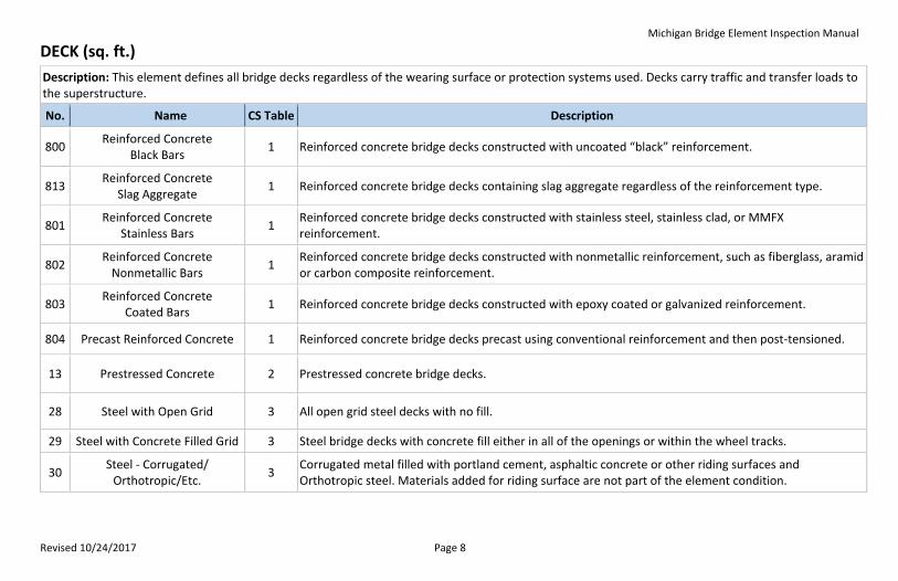
Description: This element defines all bridge decks regardless of the wearing surface or protection systems used. Decks carry traffic and transfer loads to the superstructure.
No. Name CS Table Description
800 Reinforced Concrete
Black Bars 1 Reinforced concrete bridge decks constructed with uncoated “black” reinforcement.
813 Reinforced Concrete
Slag Aggregate 1 Reinforced concrete bridge decks containing slag aggregate regardless of the reinforcement type.
801 Reinforced Concrete
Stainless Bars 1
Reinforced concrete bridge decks constructed with stainless steel, stainless clad, or MMFX reinforcement.
802 Reinforced Concrete
Nonmetallic Bars 1
Reinforced concrete bridge decks constructed with nonmetallic reinforcement, such as fiberglass, aramid or carbon composite reinforcement.
803 Reinforced Concrete
Coated Bars 1 Reinforced concrete bridge decks constructed with epoxy coated or galvanized reinforcement.
804 Precast Reinforced Concrete 1 Reinforced concrete bridge decks precast using conventional reinforcement and then post-tensioned.
13 Prestressed Concrete 2 Prestressed concrete bridge decks.
28 Steel with Open Grid 3 All open grid steel decks with no fill.
29 Steel with Concrete Filled Grid 3 Steel bridge decks with concrete fill either in all of the openings or within the wheel tracks.
30 Steel - Corrugated/
Orthotropic/Etc. 3
Corrugated metal filled with portland cement, asphaltic concrete or other riding surfaces and Orthotropic steel. Materials added for riding surface are not part of the element condition.
Michigan Bridge Element Inspection Manual
Revised 10/24/2017 Page 9
DECK (continued)
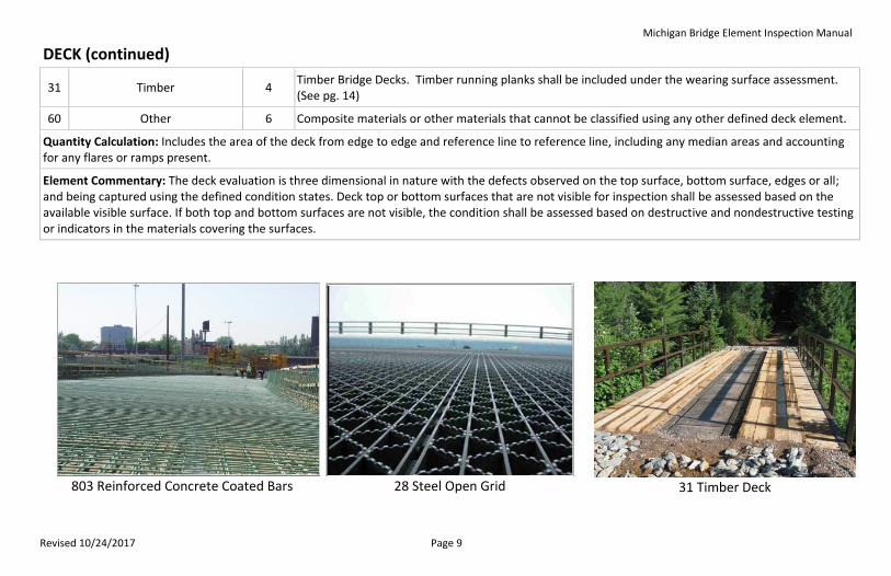
31 Timber 4 Timber Bridge Decks. Timber running planks shall be included under the wearing surface assessment. (See pg. 14)
60 Other 6 Composite materials or other materials that cannot be classified using any other defined deck element.
Quantity Calculation: Includes the area of the deck from edge to edge and reference line to reference line, including any median areas and accounting for any flares or ramps present.
Element Commentary: The deck evaluation is three dimensional in nature with the defects observed on the top surface, bottom surface, edges or all; and being captured using the defined condition states. Deck top or bottom surfaces that are not visible for inspection shall be assessed based on the available visible surface. If both top and bottom surfaces are not visible, the condition shall be assessed based on destructive and nondestructive testing or indicators in the materials covering the surfaces.
803 Reinforced Concrete Coated Bars
28 Steel Open Grid
31 Timber Deck
Michigan Bridge Element Inspection Manual
Revised 10/24/2017 Page 10
SLAB (sq. ft.)
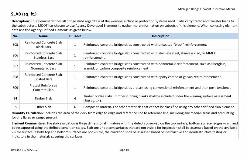
Description: This element defines all bridge slabs regardless of the wearing surface or protection systems used. Slabs carry traffic and transfer loads to the substructure. MDOT has chosen to use Agency Developed Elements to gather more information on subsets of this element. When collecting element data use the Agency Defined Elements as given below.
No. Name CS Table Description
805 Reinforced Concrete Slab
Black Bars 1 Reinforced concrete bridge slabs constructed with uncoated “black” reinforcement.
806 Reinforced Concrete Slab
Stainless Bars 1
Reinforced concrete bridge slabs constructed with stainless steel, stainless clad, or MMFX reinforcement.
807 Reinforced Concrete Slab
Nonmetallic Bars 1
Reinforced concrete bridge slabs constructed with nonmetallic reinforcement, such as fiberglass, aramid, or carbon composite reinforcement.
808 Reinforced Concrete Slab
Coated Bars 1 Reinforced concrete bridge slabs constructed with epoxy coated or galvanized reinforcement.
809 Precast Reinforced
Concrete Slab 1 Reinforced concrete bridge slabs precast using conventional reinforcement and then post-tensioned.
54 Timber Slab 4 Timber bridge slabs. Timber running planks shall be included under the wearing surface assessment. (See pg. 14)
65 Other Slab 6 Composite materials or other materials that cannot be classified using any other defined slab element.
Quantity Calculation: Includes the area of the deck from edge to edge and reference line to reference line, including any median areas and accounting for any flares or ramps present.
Element Commentary: The slab evaluation is three dimensional in nature with the defects observed on the top surface, bottom surface, edges or all; and being captured using the defined condition states. Slab top or bottom surfaces that are not visible for inspection shall be assessed based on the available visible surface. If both top and bottom surfaces are not visible, the condition shall be assessed based on destructive and nondestructive testing or indicators in the materials covering the surfaces.
Michigan Bridge Element Inspection Manual
Revised 10/24/2017 Page 11
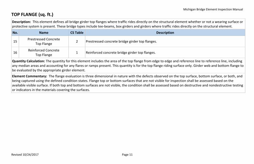
TOP FLANGE (sq. ft.)
Description: This element defines all bridge girder top flanges where traffic rides directly on the structural element whether or not a wearing surface or protective system is present. These bridge types include tee-beams, box girders and girders where traffic rides directly on the structural element.
No. Name CS Table Description
15 Prestressed Concrete
Top Flange 2 Prestressed concrete bridge girder top flanges.
16 Reinforced Concrete
Top Flange 1 Reinforced concrete bridge girder top flanges.
Quantity Calculation: The quantity for this element includes the area of the top flange from edge to edge and reference line to reference line, including any median areas and accounting for any flares or ramps present. This quantity is for the top flange riding surface only. Girder web and bottom flange to be evaluated by the appropriate girder element.
Element Commentary: The flange evaluation is three dimensional in nature with the defects observed on the top surface, bottom surface, or both, and being captured using the defined condition states. Flange top or bottom surfaces that are not visible for inspection shall be assessed based on the available visible surface. If both top and bottom surfaces are not visible, the condition shall be assessed based on destructive and nondestructive testing or indicators in the materials covering the surfaces.
Michigan Bridge Element Inspection Manual
Revised 10/24/2017 Page 12
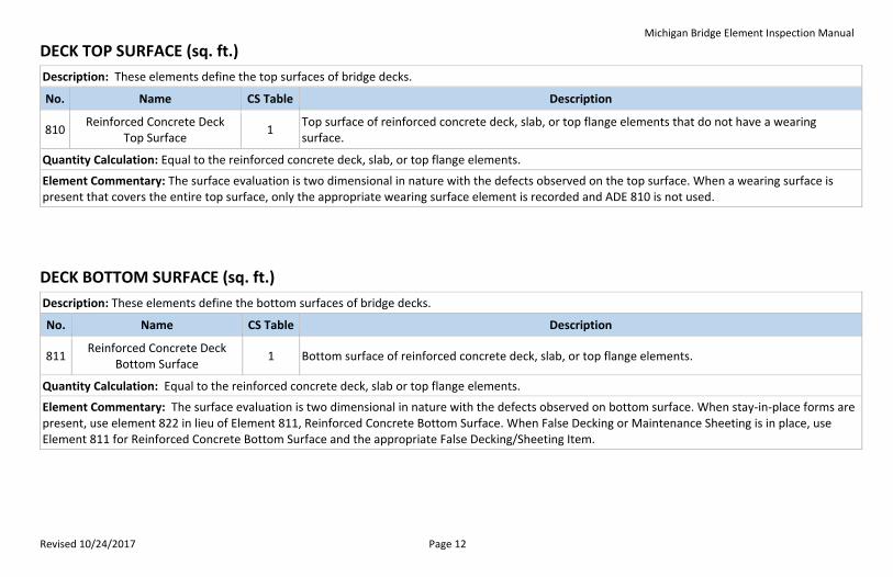
DECK TOP SURFACE (sq. ft.)
Description: These elements define the top surfaces of bridge decks.
No. Name CS Table Description
810 Reinforced Concrete Deck
Top Surface 1
Top surface of reinforced concrete deck, slab, or top flange elements that do not have a wearing surface.
Quantity Calculation: Equal to the reinforced concrete deck, slab, or top flange elements.
Element Commentary: The surface evaluation is two dimensional in nature with the defects observed on the top surface. When a wearing surface is present that covers the entire top surface, only the appropriate wearing surface element is recorded and ADE 810 is not used.
DECK BOTTOM SURFACE (sq. ft.)
Description: These elements define the bottom surfaces of bridge decks.
No. Name CS Table Description
811 Reinforced Concrete Deck
Bottom Surface 1 Bottom surface of reinforced concrete deck, slab, or top flange elements.
Quantity Calculation: Equal to the reinforced concrete deck, slab or top flange elements.
Element Commentary: The surface evaluation is two dimensional in nature with the defects observed on bottom surface. When stay-in-place forms are present, use element 822 in lieu of Element 811, Reinforced Concrete Bottom Surface. When False Decking or Maintenance Sheeting is in place, use Element 811 for Reinforced Concrete Bottom Surface and the appropriate False Decking/Sheeting Item.
Michigan Bridge Element Inspection Manual
Revised 10/24/2017 Page 13
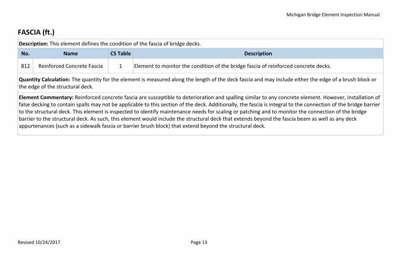
FASCIA (ft.)
Description: This element defines the condition of the fascia of bridge decks.
No. Name CS Table Description
812 Reinforced Concrete Fascia 1 Element to monitor the condition of the bridge fascia of reinforced concrete decks.
Quantity Calculation: The quantity for the element is measured along the length of the deck fascia and may include either the edge of a brush block or the edge of the structural deck.
Element Commentary: Reinforced concrete fascia are susceptible to deterioration and spalling similar to any concrete element. However, installation of false decking to contain spalls may not be applicable to this section of the deck. Additionally, the fascia is integral to the connection of the bridge barrier to the structural deck. This element is inspected to identify maintenance needs for scaling or patching and to monitor the connection of the bridge barrier to the structural deck. As such, this element would include the structural deck that extends beyond the fascia beam as well as any deck appurtenances (such as a sidewalk fascia or barrier brush block) that extend beyond the structural deck.
Michigan Bridge Element Inspection Manual
Revised 10/24/2017 Page 14
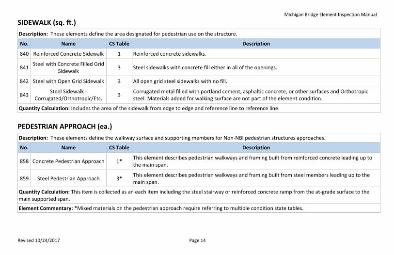
SIDEWALK (sq. ft.)
Description: These elements define the area designated for pedestrian use on the structure.
No. Name CS Table Description
840 Reinforced Concrete Sidewalk 1 Reinforced concrete sidewalks.
841 Steel with Concrete Filled Grid
Sidewalk 3 Steel sidewalks with concrete fill either in all of the openings.
842 Steel with Open Grid Sidewalk 3 All open grid steel sidewalks with no fill.
843 Steel Sidewalk -
Corrugated/Orthotropic/Etc. 3
Corrugated metal filled with portland cement, asphaltic concrete, or other surfaces and Orthotropic steel. Materials added for walking surface are not part of the element condition.
Quantity Calculation: Includes the area of the sidewalk from edge to edge and reference line to reference line.
PEDESTRIAN APPROACH (ea.)
Description: These elements define the walkway surface and supporting members for Non-NBI pedestrian structures approaches.
No. Name CS Table Description
858 Concrete Pedestrian Approach 1* This element describes pedestrian walkways and framing built from reinforced concrete leading up to the main span.
859 Steel Pedestrian Approach 3* This element describes pedestrian walkways and framing built from steel members leading up to the main span.
Quantity Calculation: This item is collected as an each item including the steel stairway or reinforced concrete ramp from the at-grade surface to the main supported span.
Element Commentary: *Mixed materials on the pedestrian approach require referring to multiple condition state tables.
Michigan Bridge Element Inspection Manual
Revised 10/24/2017 Page 15
WEARING SURFACES (sq. ft.)
Description: This element is for all decks/slabs overlays. MDOT has chosen to use Agency Defined Elements (ADE) to gather more information on subsets of this element. When collecting element data use the ADE as given below.
No. Name CS Table Description
815 Shallow Rigid Overlay 7 Rigid overlay (concrete, latex modified concrete or silica fume concrete) that does not extend below the top layer of reinforcement.
816 Thin Overlay 7 Thin overlay consisting of epoxy, methyl methacrylate, or polyester polymer and coarse aggregate that is generally 1/4” to 3/8” thick. Does not include healer sealers.
817 Asphalt Overlay w/
membrane 7 Hot Mix asphalt overlay with a waterproofing membrane.
818 Asphalt Overlay w/out
membrane 7 Hot Mix asphalt overlay without a waterproofing membrane.
819 Timber Running Planks 7 Timber running planks used as a wearing surface.
Quantity Calculation: Include the area of the deck/slab that is protected by this wearing surface.
Michigan Bridge Element Inspection Manual
Revised 10/24/2017 Page 16
FALSE DECKING, MAINTENANCE SHEETING AND STAY-IN_PLACE FORMS (sq. ft.)
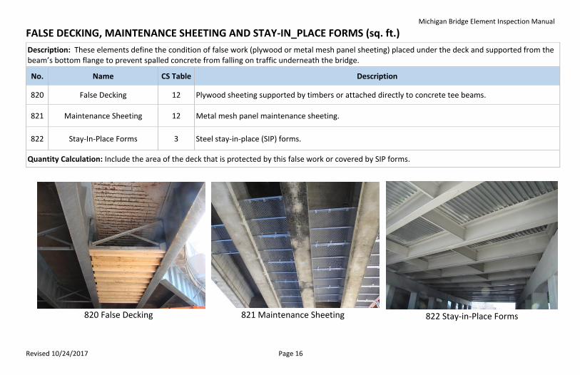
Description: These elements define the condition of false work (plywood or metal mesh panel sheeting) placed under the deck and supported from the beam’s bottom flange to prevent spalled concrete from falling on traffic underneath the bridge.
No. Name CS Table Description
820 False Decking 12 Plywood sheeting supported by timbers or attached directly to concrete tee beams.
821 Maintenance Sheeting 12 Metal mesh panel maintenance sheeting.
822 Stay-In-Place Forms 3 Steel stay-in-place (SIP) forms.
Quantity Calculation: Include the area of the deck that is protected by this false work or covered by SIP forms.
820 False Decking
821 Maintenance Sheeting
822 Stay-in-Place Forms
Michigan Bridge Element Inspection Manual
Revised 10/24/2017 Page 17
JOINTS (ft.)
Description: These elements define bridge deck or slab joints and pavement relief joints.
No. Name CS Table Description
300 Strip Seal Expansion Joint 8 Expansion joint devices that utilize a neoprene type waterproof gland with some type of metal extrusion or other system to anchor the gland.
301 Pourable Joint Seal 8 Joints filled with a pourable seal with or without a backer.
302 Compression Joint Seal 8 Joints filled with a preformed compression type seal. This joint does not have an anchor system to confine the seal.
303 Assembly Joint with Seal 8 Joints filled with an assembly mechanism that have a seal.
304 Open Expansion Joint 8 Joints that are open and not sealed.
305 Assembly Joint Without Seal 8 Joints that are open and not sealed. This element includes finger and sliding plate joints.
306 Other Joints 8 Joints that cannot be classified using any other defined joint element.
828 Pressure Relief Joints 8 Joints where a pressure relief joint (PRJ) material has been installed in the approach pavement.
Quantity Calculation: Sum the lengths of all joints measured along the skew angle.
Element Commentary: Other Joints shall also include partial depth strip seal and block out style expansion joints.
Michigan Bridge Element Inspection Manual
Revised 10/24/2017 Page 18
APPROACH SLAB (sq. ft.)
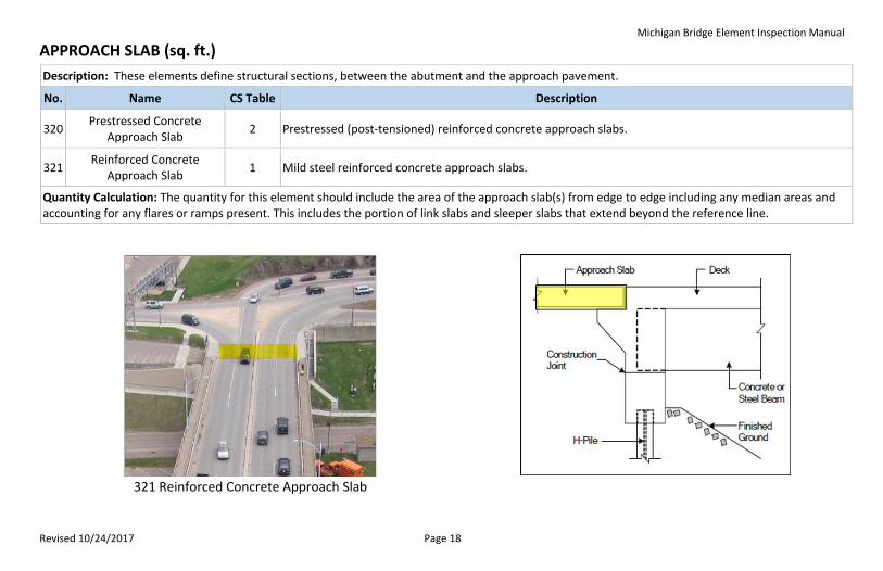
Description: These elements define structural sections, between the abutment and the approach pavement.
No. Name CS Table Description
320 Prestressed Concrete
Approach Slab 2 Prestressed (post-tensioned) reinforced concrete approach slabs.
321 Reinforced Concrete
Approach Slab 1 Mild steel reinforced concrete approach slabs.
Quantity Calculation: The quantity for this element should include the area of the approach slab(s) from edge to edge including any median areas and accounting for any flares or ramps present. This includes the portion of link slabs and sleeper slabs that extend beyond the reference line.
321 Reinforced Concrete Approach Slab
Michigan Bridge Element Inspection Manual
Revised 10/24/2017 Page 19
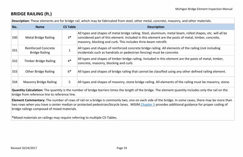
BRIDGE RAILING (ft.)
Description: These elements are for bridge rail, which may be fabricated from steel, other metal, concrete, masonry, and other materials.
No. Name CS Table Description
330 Metal Bridge Railing 3* All types and shapes of metal bridge railing. Steel, aluminum, metal beam, rolled shapes, etc. will all be considered part of this element. Included in this element are the posts of metal, timber, concrete, masonry, blocking and curb. This includes thrie-beam retrofit.
331 Reinforced Concrete
Bridge Railing 1
All types and shapes of reinforced concrete bridge railing. All elements of the railing (not including incidentals such as handrails or pedestrian fencing) must be concrete.
332 Timber Bridge Railing 4* All types and shapes of timber bridge railing. Included in this element are the posts of metal, timber, concrete, masonry, blocking and curb.
333 Other Bridge Railing 6* All types and shapes of bridge railing that cannot be classified using any other defined railing element.
334 Masonry Bridge Railing 5 All types and shapes of masonry, stone bridge railing. All elements of the railing must be masonry, stone.
Quantity Calculation: The quantity is the number of bridge barriers times the length of the bridge. The element quantity includes only the rail on the bridge from reference line to reference line.
Element Commentary: The number of rows of rail on a bridge is commonly two, one on each side of the bridge. In some cases, there may be more than two rows when you have a center median or protected pedestrian/bicycle lanes. MiSIM Chapter 5 provides additional guidance for proper coding of bridge railings composed of mixed materials. *Mixed materials on railings may require referring to multiple CS-Tables.
Michigan Bridge Element Inspection Manual
Revised 10/24/2017 Page 20
SUPERSTRUCTURE
Superstructure elements described in this section transmit loads from decks to the substructure. These elements include girders, trusses, arches and floor systems. The floor systems include floor beams and stringers. Additional elements in this group include cables, gusset plates and pin and hanger assemblies. These elements do not include bracing components such as diaphragms, cross bracing or portal sway bracing. Girder elements transmit the loads from the deck into the substructure. Elements listed include closed web (boxes) and open girders (I sections). The materials include steel, reinforced and prestressed concrete and timber. Stringer elements are part of a floor system and transmit load from the deck into the floor system, such as floor beams. Floor beam elements are the intermediate transverse load carrying members and can be constructed from steel, concrete and timber. Truss and Arch elements include materials of steel, concrete, timber and masonry; and are the main load carrying members for the span. Miscellaneous superstructure elements include elements such as steel pin, pin and hanger assemblies, steel gusset plates and main and secondary cables.
Michigan Bridge Element Inspection Manual
Revised 10/24/2017 Page 21
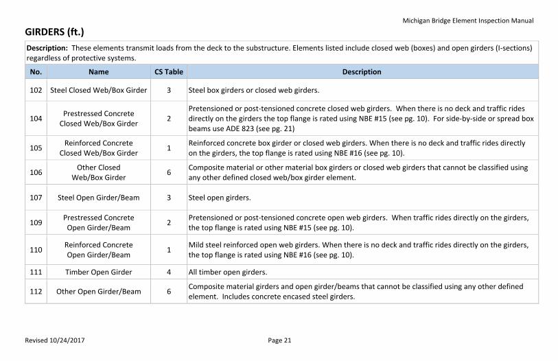
GIRDERS (ft.)
Description: These elements transmit loads from the deck to the substructure. Elements listed include closed web (boxes) and open girders (I-sections) regardless of protective systems.
No. Name CS Table Description
102 Steel Closed Web/Box Girder 3 Steel box girders or closed web girders.
104 Prestressed Concrete
Closed Web/Box Girder 2
Pretensioned or post-tensioned concrete closed web girders. When there is no deck and traffic rides directly on the girders the top flange is rated using NBE #15 (see pg. 10). For side-by-side or spread box beams use ADE 823 (see pg. 21)
105 Reinforced Concrete
Closed Web/Box Girder 1
Reinforced concrete box girder or closed web girders. When there is no deck and traffic rides directly on the girders, the top flange is rated using NBE #16 (see pg. 10).
106 Other Closed
Web/Box Girder 6
Composite material or other material box girders or closed web girders that cannot be classified using any other defined closed web/box girder element.
107 Steel Open Girder/Beam 3 Steel open girders.
109 Prestressed Concrete
Open Girder/Beam 2
Pretensioned or post-tensioned concrete open web girders. When traffic rides directly on the girders, the top flange is rated using NBE #15 (see pg. 10).
110 Reinforced Concrete Open Girder/Beam
1 Mild steel reinforced open web girders. When there is no deck and traffic rides directly on the girders, the top flange is rated using NBE #16 (see pg. 10).
111 Timber Open Girder 4 All timber open girders.
112 Other Open Girder/Beam 6 Composite material girders and open girder/beams that cannot be classified using any other defined element. Includes concrete encased steel girders.
Michigan Bridge Element Inspection Manual
Revised 10/24/2017 Page 22
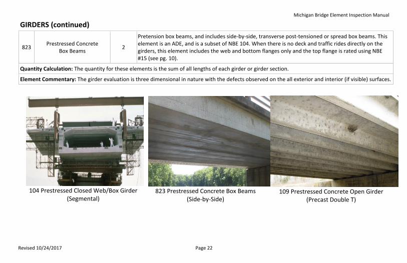
GIRDERS (continued)
823 Prestressed Concrete
Box Beams 2
Pretension box beams, and includes side-by-side, transverse post-tensioned or spread box beams. This element is an ADE, and is a subset of NBE 104. When there is no deck and traffic rides directly on the girders, this element includes the web and bottom flanges only and the top flange is rated using NBE #15 (see pg. 10).
Quantity Calculation: The quantity for these elements is the sum of all lengths of each girder or girder section.
Element Commentary: The girder evaluation is three dimensional in nature with the defects observed on the all exterior and interior (if visible) surfaces.
104 Prestressed Closed Web/Box Girder
(Segmental)
823 Prestressed Concrete Box Beams
(Side-by-Side)
109 Prestressed Concrete Open Girder
(Precast Double T)
Michigan Bridge Element Inspection Manual
Revised 10/24/2017 Page 23
FLOOR BEAMS (ft.)
Description: This element defines only elements that transversely support stringers or decks, regardless of protective systems.
No. Name CS Table Description
152 Steel Floor Beam 3 The condition evaluation for this element includes web faces and the top and bottom flange.
154 Prestressed Concrete Floor
Beam 2 Only prestressed elements.
155 Reinforced Concrete
Floor Beam 1 Only mild steel reinforced concrete.
156 Timber Floor Beam 4 Timber floor beams.
157 Other Floor Beam 6 Composite materials, or other materials that cannot be classified using any other defined elements.
Quantity Calculation: The quantity for these elements is the sum of all lengths of each floor beam.
Element Commentary: The floor beam evaluation is three dimensional in nature with the defects observed on all exterior surfaces.
Michigan Bridge Element Inspection Manual
Revised 10/24/2017 Page 24
STRINGERS (ft.)
Description: These superstructure elements transmit loads from the deck to the floor system, such as floor beams, regardless of protective systems. These elements define members that support the deck in a stringer floor beam system.
No. Name CS Table Description
113 Steel Stringer 3 Steel members that support the deck in a stringer floor beam system.
115 Prestressed Concrete
Stringer 2
Pretensioned or post-tensioned concrete members that support the deck in a stringer floor beam system.
116 Reinforced Concrete
Stringer 1 Mild steel reinforced concrete members that support the deck in a stringer floor beam system.
117 Timber Stringer 4 Timber members that support the deck in a stringer floor beam system.
118 Other Stringer 6 Composite materials or other materials that cannot be classified using any other defined elements.
Quantity Calculation: The quantity for these elements is the sum of all lengths of each section.
Element Commentary: The stringer evaluation is three dimensional in nature with the defects observed on all exterior surfaces.
Michigan Bridge Element Inspection Manual
Revised 10/24/2017 Page 25
TRUSSES (ft.)
Description: This element defines all truss components, including all tension and compression members for through and deck trusses, regardless of protective system.
No. Name CS Table Description
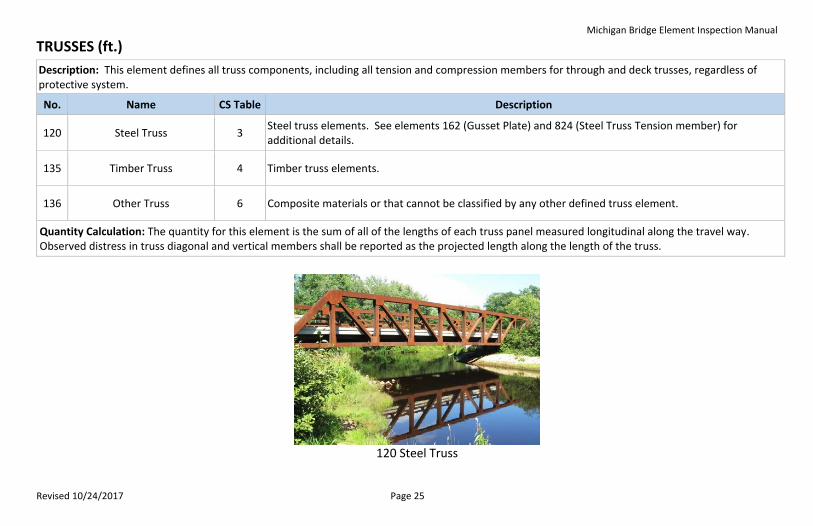
120 Steel Truss 3 Steel truss elements. See elements 162 (Gusset Plate) and 824 (Steel Truss Tension member) for additional details.
135 Timber Truss 4 Timber truss elements.
136 Other Truss 6 Composite materials or that cannot be classified by any other defined truss element.
Quantity Calculation: The quantity for this element is the sum of all of the lengths of each truss panel measured longitudinal along the travel way. Observed distress in truss diagonal and vertical members shall be reported as the projected length along the length of the truss.
120 Steel Truss
Michigan Bridge Element Inspection Manual
Revised 10/24/2017 Page 26
ARCHES (ft.)
Description: This element defines arches regardless of materials type or protective system.
No. Name CS Table Description
141 Steel Arch 3 Steel arches. See element 824 (Steel Arch Tension member) for additional details.
142 Other Arch 6 Composite materials and arches, regardless of type, that cannot be classified using any other defined arch element.
143 Prestressed Concrete Arch 2 Pretensioned or post-tensioned concrete arches.
144 Reinforced Concrete Arch 1 Mild steel reinforced concrete arches.
145 Masonry Arch 5 Masonry or stacked stone arches.
146 Timber Arch 4 Timber arches.
Quantity Calculation: The quantity for this element is the sum of the length of each arch horizontally between spring lines and measured longitudinal to the travel way. For filled arches, the arch quantity shall be measured from spring line to spring line. The length below the spring line is considered substructure.
Element Commentary: Observed distress in arch diagonals and vertical members (including spandrel columns) shall be reported as the projected length along the arch length.
Michigan Bridge Element Inspection Manual
Revised 10/24/2017 Page 27
CABLES (See Description)
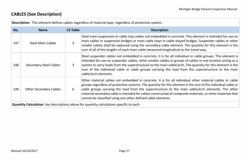
Description: This element defines cables regardless of material type, regardless of protective system.
No. Name CS Table Description
147 Steel Main Cables 3
Steel main suspension or cable stay cables not embedded in concrete. This element is intended for use on main cables in suspension bridges or main cable stays in cable-stayed bridges. Suspender cables or other smaller cables shall be captured using the secondary cable element. The quantity for this element is the sum of all of the lengths of each main cable measured longitudinal to the travel way.
148 Secondary Steel Cables 3
Steel suspender cables not embedded in concrete. It is for all individual or cable groups. This element is intended for use on suspender cables, other smaller cables or groups of cables in one location acting as a system to carry loads from the superstructure to the main cable/arch. The quantity for this element is the sum of the individual cable or cable groups carrying the load from the superstructure to the main cable/arch elements.
149 Other Secondary Cables 6
Other material cables not embedded in concrete. It is for all individual other material cables or cable groups regardless of protective systems. The quantity for this element is the sum of the individual cable or cable groups carrying the load from the superstructure to the main cable/arch elements. The other material secondary cable is intended for cables constructed of composite materials, or other materials that cannot be classified using any other defined cable elements.
Quantity Calculation: See descriptions above for quantity calculations specific to each.
Michigan Bridge Element Inspection Manual
Revised 10/24/2017 Page 28
MISCELLANEOUS SUPERSTRUCTURE ELEMENTS (ea.)
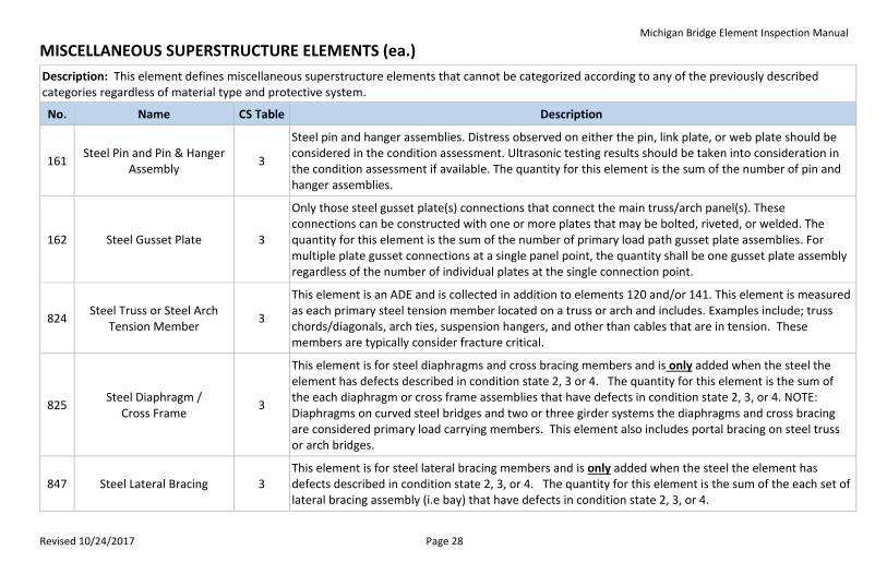
Description: This element defines miscellaneous superstructure elements that cannot be categorized according to any of the previously described categories regardless of material type and protective system.
No. Name CS Table Description
161 Steel Pin and Pin & Hanger
Assembly 3
Steel pin and hanger assemblies. Distress observed on either the pin, link plate, or web plate should be considered in the condition assessment. Ultrasonic testing results should be taken into consideration in the condition assessment if available. The quantity for this element is the sum of the number of pin and hanger assemblies.
162 Steel Gusset Plate 3
Only those steel gusset plate(s) connections that connect the main truss/arch panel(s). These connections can be constructed with one or more plates that may be bolted, riveted, or welded. The quantity for this element is the sum of the number of primary load path gusset plate assemblies. For multiple plate gusset connections at a single panel point, the quantity shall be one gusset plate assembly regardless of the number of individual plates at the single connection point.
824 Steel Truss or Steel Arch
Tension Member 3
This element is an ADE and is collected in addition to elements 120 and/or 141. This element is measured as each primary steel tension member located on a truss or arch and includes. Examples include; truss chords/diagonals, arch ties, suspension hangers, and other than cables that are in tension. These members are typically consider fracture critical.
825 Steel Diaphragm /
Cross Frame 3
This element is for steel diaphragms and cross bracing members and is only added when the steel the element has defects described in condition state 2, 3 or 4. The quantity for this element is the sum of the each diaphragm or cross frame assemblies that have defects in condition state 2, 3, or 4. NOTE: Diaphragms on curved steel bridges and two or three girder systems the diaphragms and cross bracing are considered primary load carrying members. This element also includes portal bracing on steel truss or arch bridges.
847 Steel Lateral Bracing 3 This element is for steel lateral bracing members and is only added when the steel the element has defects described in condition state 2, 3, or 4. The quantity for this element is the sum of the each set of lateral bracing assembly (i.e bay) that have defects in condition state 2, 3, or 4.
Michigan Bridge Element Inspection Manual
Revised 10/24/2017 Page 29
MISCELLANEOUS SUPERSTRUCTURE ELEMENTS (continued)
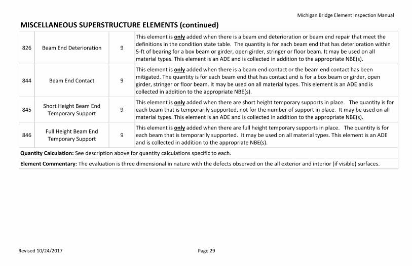
826 Beam End Deterioration 9
This element is only added when there is a beam end deterioration or beam end repair that meet the definitions in the condition state table. The quantity is for each beam end that has deterioration within 5-ft of bearing for a box beam or girder, open girder, stringer or floor beam. It may be used on all material types. This element is an ADE and is collected in addition to the appropriate NBE(s).
844 Beam End Contact 9
This element is only added when there is a beam end contact or the beam end contact has been mitigated. The quantity is for each beam end that has contact and is for a box beam or girder, open girder, stringer or floor beam. It may be used on all material types. This element is an ADE and is collected in addition to the appropriate NBE(s).
845 Short Height Beam End
Temporary Support 9
This element is only added when there are short height temporary supports in place. The quantity is for each beam that is temporarily supported, not for the number of support in place. It may be used on all material types. This element is an ADE and is collected in addition to the appropriate NBE(s).
846 Full Height Beam End Temporary Support
9 This element is only added when there are full height temporary supports in place. The quantity is for each beam that is temporarily supported. It may be used on all material types. This element is an ADE and is collected in addition to the appropriate NBE(s).
Quantity Calculation: See description above for quantity calculations specific to each.
Element Commentary: The evaluation is three dimensional in nature with the defects observed on the all exterior and interior (if visible) surfaces.
Michigan Bridge Element Inspection Manual
Revised 10/24/2017 Page 30
PROTECTIVE COATING (sq. ft.)
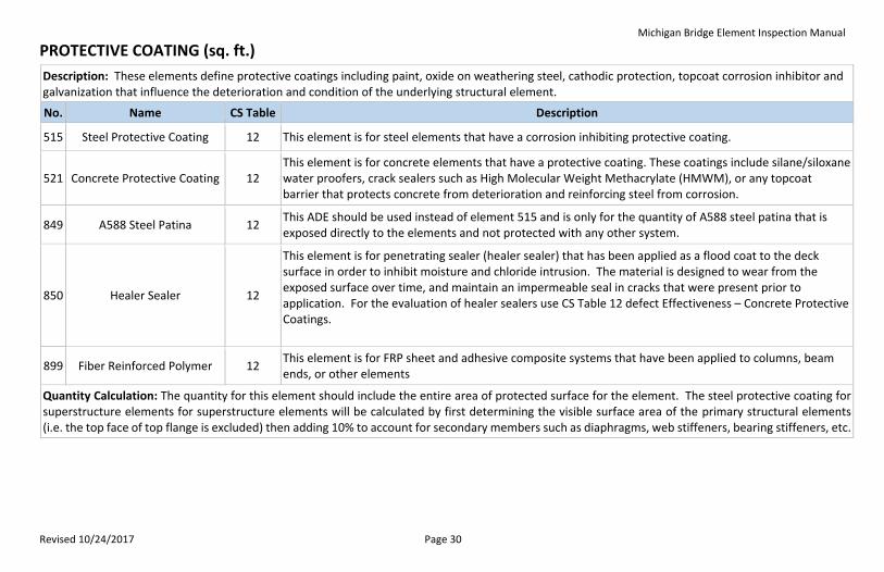
Description: These elements define protective coatings including paint, oxide on weathering steel, cathodic protection, topcoat corrosion inhibitor and galvanization that influence the deterioration and condition of the underlying structural element.
No. Name CS Table Description
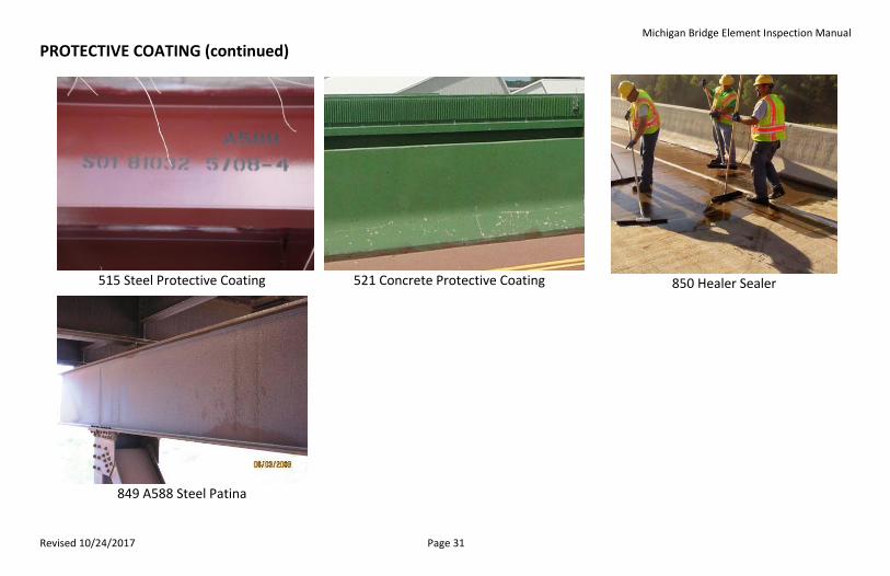
515 Steel Protective Coating 12 This element is for steel elements that have a corrosion inhibiting protective coating.
521 Concrete Protective Coating 12 This element is for concrete elements that have a protective coating. These coatings include silane/siloxane water proofers, crack sealers such as High Molecular Weight Methacrylate (HMWM), or any topcoat barrier that protects concrete from deterioration and reinforcing steel from corrosion.
849 A588 Steel Patina 12 This ADE should be used instead of element 515 and is only for the quantity of A588 steel patina that is exposed directly to the elements and not protected with any other system.
850 Healer Sealer 12
This element is for penetrating sealer (healer sealer) that has been applied as a flood coat to the deck surface in order to inhibit moisture and chloride intrusion. The material is designed to wear from the exposed surface over time, and maintain an impermeable seal in cracks that were present prior to application. For the evaluation of healer sealers use CS Table 12 defect Effectiveness – Concrete Protective Coatings.
899 Fiber Reinforced Polymer 12 This element is for FRP sheet and adhesive composite systems that have been applied to columns, beam ends, or other elements
Quantity Calculation: The quantity for this element should include the entire area of protected surface for the element. The steel protective coating for superstructure elements for superstructure elements will be calculated by first determining the visible surface area of the primary structural elements (i.e. the top face of top flange is excluded) then adding 10% to account for secondary members such as diaphragms, web stiffeners, bearing stiffeners, etc.
Michigan Bridge Element Inspection Manual
Revised 10/24/2017 Page 31
PROTECTIVE COATING (continued)
515 Steel Protective Coating
521 Concrete Protective Coating
850 Healer Sealer
(Healer Sealer)
849 A588 Steel Patina
Michigan Bridge Element Inspection Manual
Revised 10/24/2017 Page 32
BEARINGS (ea.)
Description: These elements define bridge bearings.
No. Name CS Table Description
310 Elastomeric Bearing 11 This element defines bridge bearings that are constructed primarily of elastomers, with or without fabric or metal reinforcement.
311 Moveable Bearing 11 This element defines bridge bearings that provide for both rotation and longitudinal movement by means of roller, rocker, or sliding mechanisms.
312 Enclosed/Concealed
Bearing 11
This element defines bridge bearings that are enclosed so that they are not open for detailed inspection. This element should be used for box girder hinges. In cases where the bearing material is not visible, the inspector shall assess the condition based on alignment, grade across the joint, persistence of debris, or other indirect indicators of the condition.
313 Fixed Bearing 11 This element defines bridge bearings that provide for rotation only (no longitudinal movement).
314 Pot Bearing 11 This element defines high load bearings with confined elastomer. The bearing may be fixed against horizontal movement, guided to allow sliding in one direction, or floating to allow sliding in any direction.
315 Disc Bearing 11 This element defines high load bearings with a hard plastic disk. This bearing may be fixed against horizontal movement, guided to allow movement in one direction, or floating to allow sliding in any direction.
316 Other Bearing 11 This element defines other material bridge bearings, regardless of translation or rotation constraints, that cannot be classified by any other defined bearing element.
Quantity Calculation: The quantity is the sum of each bearing type.
Michigan Bridge Element Inspection Manual
Revised 10/24/2017 Page 33
SUBSTRUCTURE
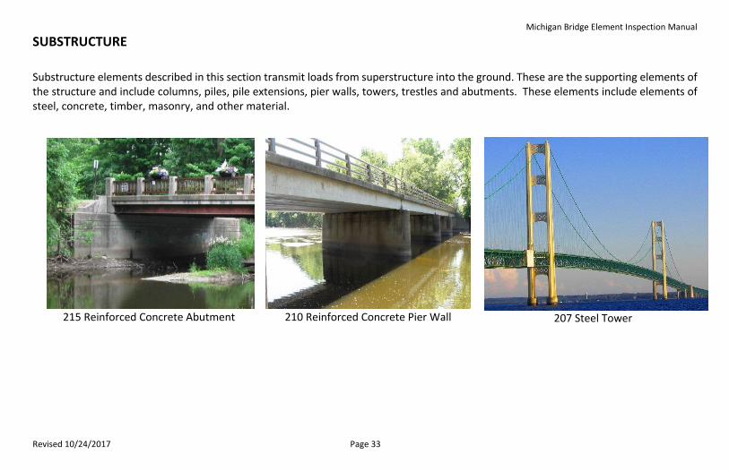
Substructure elements described in this section transmit loads from superstructure into the ground. These are the supporting elements of the structure and include columns, piles, pile extensions, pier walls, towers, trestles and abutments. These elements include elements of steel, concrete, timber, masonry, and other material.
215 Reinforced Concrete Abutment
210 Reinforced Concrete Pier Wall
207 Steel Tower
Michigan Bridge Element Inspection Manual
Revised 10/24/2017 Page 34
ABUTMENT (ft.)
Description: These elements define abutments, regardless of protective system.
No. Name CS Table Description
215 Reinforced Concrete
Abutment 1
Mild steel reinforced concrete abutments including the sheet material retaining the embankment and wingwalls, abutment extensions, and any other monolithically placed concrete elements up to the first construction joint (cold joint, water stop, etc.).
216 Timber Abutment 4 Timber abutments including the sheet material retaining the embankment and wingwalls, abutment extensions, and any other monolithically placed concrete elements up to the first construction joint (plank butt joint, etc.).
217 Masonry Abutment 5 Abutments constructed of block or stone placed with or without mortar.
218 Other Abutment 6 Other material abutment systems that cannot be classified by any other defined abutment element, including the sheet material retaining the embankment and wingwalls, abutment extensions.
219 Steel Abutment 3 Steel abutments including the sheet material retaining the embankment and wingwalls, and abutment extensions
860 MSE Abutment 13 Mechanically Stabilized Earth (MSE) abutments including the reinforced concrete stub, panels, coping, and drainage system. When piles are exposed use the appropriate material specific element.
Quantity Calculation: The quantity for these elements are the sum of the width of the abutment with monolithic wingwalls and abutments extensions measured along the skew angle. Wingwalls that are not monolithic with the abutment shall not be included in the abutment or assessment of the abutment element but should be added as a separate Wingwall Element.

Michigan Bridge Element Inspection Manual
Revised 10/24/2017 Page 35
WINGWALL (ea.)
Description: These elements define abutments, regardless of protective system.
No. Name CS Table Description
852 Reinforced Concrete
Wingwall 1 Mild steel reinforced concrete wingwalls.
853 Timber Wingwall 4 Wingwalls constructed of timber material.
854 Masonry Wingwall 5 Wingwalls constructed of block or stone placed with or without mortar.
855 Other Wingwall 6 Other material wingwall systems that cannot be classified by any other defined element
856 Steel Wingwall 3 Steel wingwalls including the sheet pile or plate material.
Quantity Calculation: The quantity for these elements is the sum of each wingwall that is attached or adjacent to the abutment or culvert. These elements are not monolithic with the abutment.
Michigan Bridge Element Inspection Manual
Revised 10/24/2017 Page 36
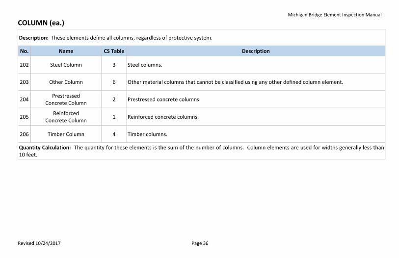
COLUMN (ea.)
Description: These elements define all columns, regardless of protective system.
No. Name CS Table Description
202 Steel Column 3 Steel columns.
203 Other Column 6 Other material columns that cannot be classified using any other defined column element.
204 Prestressed
Concrete Column 2 Prestressed concrete columns.
205 Reinforced
Concrete Column 1 Reinforced concrete columns.
206 Timber Column 4 Timber columns.
Quantity Calculation: The quantity for these elements is the sum of the number of columns. Column elements are used for widths generally less than 10 feet.
Michigan Bridge Element Inspection Manual
Revised 10/24/2017 Page 37
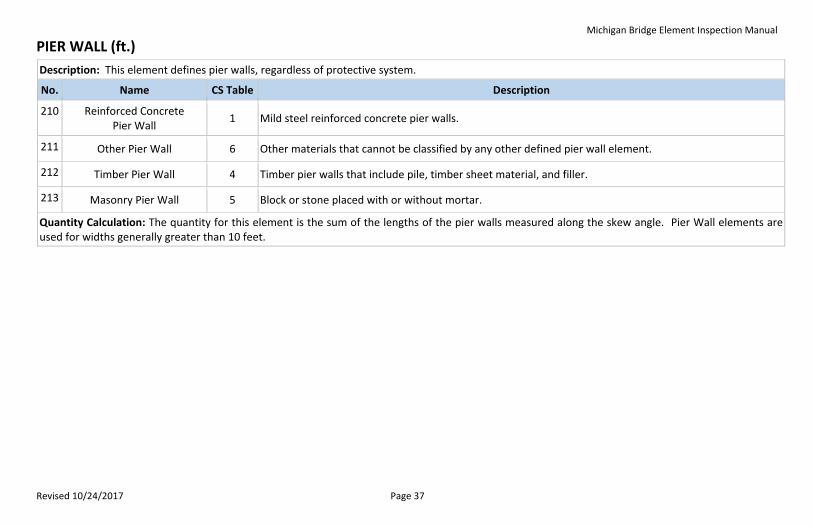
PIER WALL (ft.)
Description: This element defines pier walls, regardless of protective system.
No. Name CS Table Description
210 Reinforced Concrete Pier Wall
1 Mild steel reinforced concrete pier walls.
211 Other Pier Wall 6 Other materials that cannot be classified by any other defined pier wall element.
212 Timber Pier Wall 4 Timber pier walls that include pile, timber sheet material, and filler.
213 Masonry Pier Wall 5 Block or stone placed with or without mortar.
Quantity Calculation: The quantity for this element is the sum of the lengths of the pier walls measured along the skew angle. Pier Wall elements are used for widths generally greater than 10 feet.
Michigan Bridge Element Inspection Manual
Revised 10/24/2017 Page 38
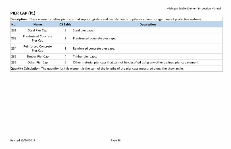
PIER CAP (ft.)
Description: These elements define pier caps that support girders and transfer loads to piles or columns, regardless of protective systems.
No. Name CS Table Description
231 Steel Pier Cap 3 Steel pier caps.
233 Prestressed Concrete
Pier Cap 2 Prestressed concrete pier caps.
234 Reinforced Concrete
Pier Cap 1 Reinforced concrete pier caps.
235 Timber Pier Cap 4 Timber pier caps.
236 Other Pier Cap 6 Other material pier caps that cannot be classified using any other defined pier cap element.
Quantity Calculation: The quantity for this element is the sum of the lengths of the pier caps measured along the skew angle.
Michigan Bridge Element Inspection Manual
Revised 10/24/2017 Page 39
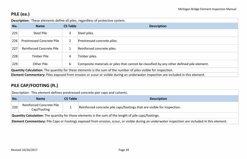
PILE (ea.)
Description: These elements define all piles, regardless of protective system.
No. Name CS Table Description
225 Steel Pile 3 Steel piles.
226 Prestressed Concrete Pile 2 Prestressed concrete piles.
227 Reinforced Concrete Pile 1 Reinforced concrete piles.
228 Timber Pile 4 Timber piles.
229 Other Pile 6 Composite materials or piles that cannot be classified by any other defined pile element.
Quantity Calculation: The quantity for these elements is the sum of the number of piles visible for inspection.
Element Commentary: Piles exposed from erosion or scour or visible during an underwater inspection are included in this element.
PILE CAP/FOOTING (ft.)
Description: This element defines prestressed concrete pier caps and culverts.
No. Name CS Table Description
220 Reinforced Concrete Pile
Cap/Footing 1 Reinforced concrete pile caps/footings that are visible for inspection.
Quantity Calculation: The quantity for these elements is the sum of the length of pile caps/footings.
Element Commentary: Pile Caps or Footings exposed from erosion, scour, or visible during an underwater inspection are included in this element.
Michigan Bridge Element Inspection Manual
Revised 10/24/2017 Page 40
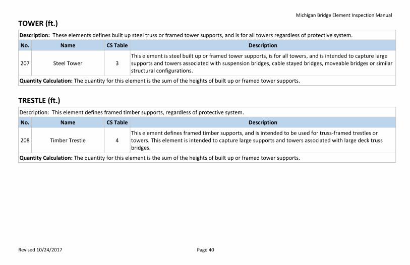
TOWER (ft.)
Description: These elements defines built up steel truss or framed tower supports, and is for all towers regardless of protective system.
No. Name CS Table Description
207 Steel Tower 3 This element is steel built up or framed tower supports, is for all towers, and is intended to capture large supports and towers associated with suspension bridges, cable stayed bridges, moveable bridges or similar structural configurations.
Quantity Calculation: The quantity for this element is the sum of the heights of built up or framed tower supports.
TRESTLE (ft.)
Description: This element defines framed timber supports, regardless of protective system.
No. Name CS Table Description
208 Timber Trestle 4 This element defines framed timber supports, and is intended to be used for truss-framed trestles or towers. This element is intended to capture large supports and towers associated with large deck truss bridges.
Quantity Calculation: The quantity for this element is the sum of the heights of built up or framed tower supports.

Michigan Bridge Element Inspection Manual
Revised 10/24/2017 Page 41
CULVERT
A culvert is a structure designed hydraulically to take advantage of submergence to increase water carrying capacity. Culverts, as distinguished from bridges, are usually covered with embankment and are composed of structural material around the entire perimeter. Some culverts are supported on spread footings with the streambed serving as the bottom of the culvert. If culverts satisfy NBIS bridge length requirement of 20 feet or greater, they may be classified as bridges in the National Bridge Inventory (NBI).
3-Sided Concrete Box Culvert
Corrugated Metal Pipe Arch Culvert
Masonry Culvert
Michigan Bridge Element Inspection Manual
Revised 10/24/2017 Page 42
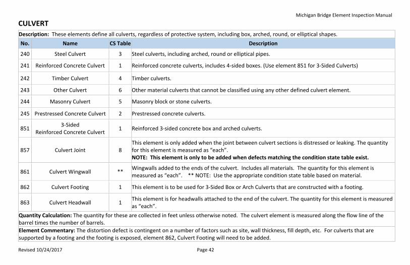
CULVERT
Description: These elements define all culverts, regardless of protective system, including box, arched, round, or elliptical shapes.
No. Name CS Table Description
240 Steel Culvert 3 Steel culverts, including arched, round or elliptical pipes.
241 Reinforced Concrete Culvert 1 Reinforced concrete culverts, includes 4-sided boxes. (Use element 851 for 3-Sided Culverts)
242 Timber Culvert 4 Timber culverts.
243 Other Culvert 6 Other material culverts that cannot be classified using any other defined culvert element.
244 Masonry Culvert 5 Masonry block or stone culverts.
245 Prestressed Concrete Culvert 2 Prestressed concrete culverts.
851 3-Sided
Reinforced Concrete Culvert 1 Reinforced 3-sided concrete box and arched culverts.
857 Culvert Joint 8 This element is only added when the joint between culvert sections is distressed or leaking. The quantity for this element is measured as “each”. NOTE: This element is only to be added when defects matching the condition state table exist.
861 Culvert Wingwall ** Wingwalls added to the ends of the culvert. Includes all materials. The quantity for this element is measured as “each”. ** NOTE: Use the appropriate condition state table based on material.
862 Culvert Footing 1 This element is to be used for 3-Sided Box or Arch Culverts that are constructed with a footing.
863 Culvert Headwall 1 This element is for headwalls attached to the end of the culvert. The quantity for this element is measured as “each”.
Quantity Calculation: The quantity for these are collected in feet unless otherwise noted. The culvert element is measured along the flow line of the barrel times the number of barrels.
Element Commentary: The distortion defect is contingent on a number of factors such as site, wall thickness, fill depth, etc. For culverts that are supported by a footing and the footing is exposed, element 862, Culvert Footing will need to be added.

Michigan Bridge Element Inspection Manual
Revised 10/24/2017 Page 43
SCOUR PROTECTION
Description: These elements define scour protection devices used to armor piers and abutments.
No. Name CS Table Description
830 Plain Rip Rap 10 Angular interlocking stone with a median diameter of 8” The quantity for this element is measured in square feet.
831 Heavy Rip Rap 10 Angular interlocking stone interlocking with a median diameter of 16”. The quantity for this element is measured in square feet.
829 Field Stone 10 Natural rounded stone with diameters varying from 8”-24”. The quantity for this element is measured in square feet.
832 Channel Armoring 10 Channel bed, banks or embankment slopes surfaced with cast-in-place concrete to resist erosion and scour. The quantity for this element is measured in square feet.
833 Articulating Concrete Block 10 Preformed units which either interlock, are held together by cables, or both to form a continuous blanket or block matrix. The quantity for this element is measured in square feet.
834 Gabion 10 Basket or compartmented rectangular containers made of wire mesh filled with cobbles or other rock. The quantity for this element is measured in feet along the length of the protected structure.
835 Grout Filled Bags 10 Fabric bags filled with grout used for scour protection. The quantity for this element is measured in feet.
836 Sheet Piling 10 A continuous line of driven steel sheeting used for scour protection. The quantity for this element is measured in feet along the length of the protected structure.
837 Other Scour
Countermeasures 10
Countermeasures that cannot be classified by any other defined scour countermeasure. The quantity for this element is measured in feet along the length of the protected structure.
Quantity Calculation: The quantities are measured along the substructure or culvert element protected and the extensions upstream and downstream from the structure. See description for units of measure.
Michigan Bridge Element Inspection Manual
Revised 10/24/2017 Page 44
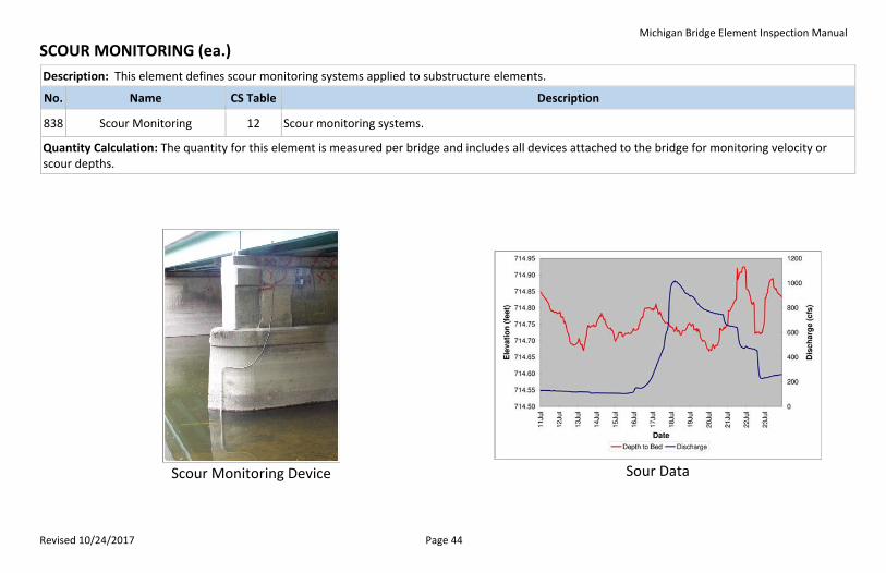
SCOUR MONITORING (ea.)
Description: This element defines scour monitoring systems applied to substructure elements.
No. Name CS Table Description
838 Scour Monitoring 12 Scour monitoring systems.
Quantity Calculation: The quantity for this element is measured per bridge and includes all devices attached to the bridge for monitoring velocity or scour depths.
Scour Monitoring Device
Sour Data
Michigan Bridge Element Inspection Manual
Revised 10/24/2017 Page 45
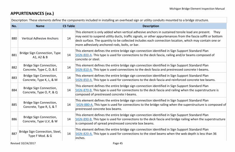
APPURTENANCES (ea.)
Description: These elements define the components included in installing an overhead sign or utility conduits mounted to a bridge structure.
No. Name CS Table Description
880 Vertical Adhesive Anchors 14
This element is only added when vertical adhesive anchors in sustained tensile load are present. They may exist to suspend utility ducts, traffic signals, or other appurtenances from the fascia soffit or bottom deck surface. The quantity to be collected includes each connection location, which may contain one or more adhesively anchored rods, bolts, or bar.
881 Bridge Sign Connection, Type
A1, A2 & B 14
This element defines the entire bridge sign connection identified in Sign Support Standard Plan SIGN-800-A. This type is used for connections to the deck fascia, railing and/or beams composed of concrete or steel.
882 Bridge Sign Connection, Concrete, Type C, D, & E
14 This element defines the entire bridge sign connection identified in Sign Support Standard Plan SIGN-810-A. This type is used connections to the deck fascia and prestressed concrete I-beams.
883 Bridge Sign Connection, Concrete, Type K, L, & M
14 This element defines the entire bridge sign connection identified in Sign Support Standard Plan SIGN-850-A. This type is used for connections to the deck fascia and reinforced concrete tee beams.
884 Bridge Sign Connection, Concrete, Type O, P, & Q
14 This element defines the entire bridge sign connection identified in Sign Support Standard Plan SIGN-870-B. This type is used for connections to the deck fascia and railing when the superstructure is composed of prestressed concrete I-beams.
885 Bridge Sign Connection, Concrete, Type R, S, & T
14 This element defines the entire bridge sign connection identified in Sign Support Standard Plan SIGN-880-A. This type is used for connections to the bridge railing when the superstructure is composed of prestressed concrete box beams.
886 Bridge Sign Connection, Concrete, Type U,V, & W
14 This element defines the entire bridge sign connection identified in Sign Support Standard Plan SIGN-890-B. This type is used for connections to the deck fascia and bridge railing when the superstructure is composed of spread prestressed concrete box beams.
887 Bridge Sign Connection, Steel,
Type F Mod. & G 14
This element defines the entire bridge sign connection identified in Sign Support Standard Plan SIGN-820-A. This type is used for connections to the steel beams when the web depth is less than 36 inches.

Michigan Bridge Element Inspection Manual
Revised 10/24/2017 Page 46
APPURTENANCES (Continued)
888 Bridge Sign Connection, Steel,
Type H, I, & J 14
This element defines the entire bridge sign connection identified in Sign Support Standard Plan SIGN-830-A. This type is used for connections to the steel beams when the web depth is equal to or greater than 36 inches.
889 Bridge Sign Connection, Steel,
Old Type C & D 14
This element defines the entire bridge sign connection identified in Sign Support Special Detail SIGN-821-A. This type is used for connections to the deck fascia, railing, and/or steel beams.
890 Bridge Sign Connection, Steel,
Type C &D 14
This element defines the entire bridge sign connection identified in Sign Support Special Detail SIGN-898-A. This type is used for connections to the deck fascia, railing, and/or steel beams.
891 Bridge Sign Connection, Steel,
Old Type E & F 14
This element defines the entire bridge sign connection identified in Sign Support Special Detail SIGN-831-A. This type is used for connections to the deck fascia, railing, and/or steel beams.
892 Bridge Sign Connection, Steel,
Type E & F 14
This element defines the entire bridge sign connection identified in Sign Support Special Detail SIGN-899-B. This type is used for connections to the deck fascia, railing, and/or steel beams.
893 Bridge Sign, Column 14 This element defines the number of vertical aluminum columns present that are secured to the steel cantilever sections. This element must be collected in conjunction with all bridge sign connection elements except Element 881.
894 Bridge Sign, Mounted 14 This element is only added when distress or damage is observed to the aluminum, plywood, or reflective signing materials.
895 Bridge Sign, Steel Bolted
Connection 14
This element is only added when distress is observed including section loss on the beam surface, missing bolts, loose bolts, shifted or deteriorated bearing pads, oversized holes, or cracks are observed on the connection to the steel beams.
896 Bridge Sign, Concrete Anchored Connection
14 This element is only added when distress is observed including concrete element deterioration, anchor pullout, missing bolts, loose bolts, or the connection is not flush to the surface.
Michigan Bridge Element Inspection Manual
Revised 10/24/2017 Page 47
APPURTENANCES (Continued)
897 Bridge Sign Bolts, Nuts, Washers, and Anchors
14
This element is only added when improper installation or deterioration compromises the integrity of the fastener. This element must be collected in conjunction with Element 895 or 896 when it is located at a connection to the deck fascia, railing, and/or beam. This includes bolts that are missing, loose, exhibit inadequate thread exposure, have insufficient edge distance, or are poorly aligned.
Quantity Calculation: The quantity for these elements is each. The condition of one element may affect another causing multiple elements to be recorded.
Michigan Bridge Element Inspection Manual
Revised 10/24/2017 Page 48
CONDITION STATE TABLES
The condition state descriptions for National Bridge Elements and Bridge Management Elements follows guidance provided by the AASHTO Bridge Element Manual and the FHWA. The condition state descriptions for Agency Defined Elements (ADEs) are defined by MDOT. This manual attempts to cover the majority of all conditions observed in the field, but during the course of an inspection, the inspector may find conditions that are not described. In these cases, the inspector should use the general description of the condition states to determine the appropriate condition. Overarching descriptors for the four condition states are as follows:
Condition State 1 (Good) – that portion of the element that has either no deterioration or the deterioration is insignificant to the management of the element, meaning that portion of the element has no condition based preventive maintenance needs or repairs. Areas of an element that have received long lasting structural repairs that restore the full capacity of the element with an expected life expectancy equal to the original element can be coded as good condition. Condition State 2 (Fair) – that portion of the element that has minor deficiencies that signifies a progression of the deterioration process. This portion of the element may need condition based preventive maintenance. Areas of the element that have received structural repairs that improve the element, but the repair is not considered equal to the original member can be coded as fair. Condition State 3 (Poor) – that portion of the element that has advanced deterioration requiring repair. The summation of the quantity of the element in poor or worse condition determines the need for repairs, rehabilitation, or replacement activities. Condition State 4 (Severe) – that portion of the element that warrants a review to determine the effect on strength or serviceability of the element or bridge; OR a structural review has been completed and the defects impact strength or serviceability of the element or bridge. Elements with a portion or all of the quantity in state 4 may often have load capacity implications warranting a structural review. Within this manual, the term structural review is defined as a review by a person qualified to evaluate the field observed conditions and make a determination of the impacts of the conditions on the performance of the element. Structural reviews may include a review of the field inspection notes and photographs, review of as-built plans or analysis as deemed appropriate to evaluate the performance of the element.
Michigan Bridge Element Inspection Manual
Revised 10/24/2017 Page 49
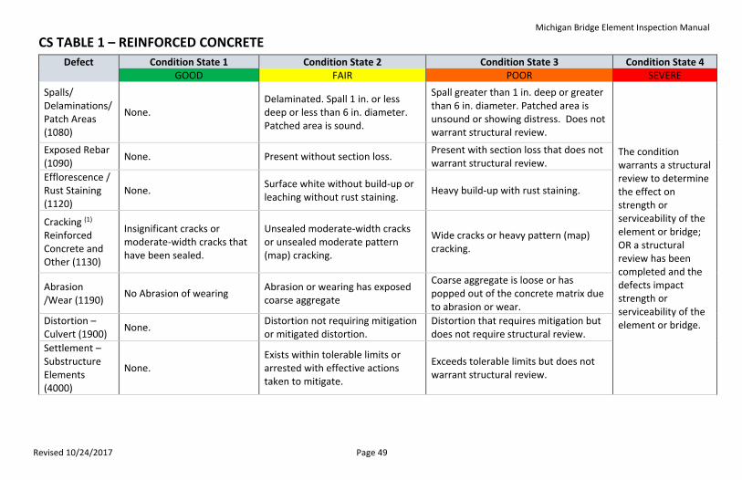
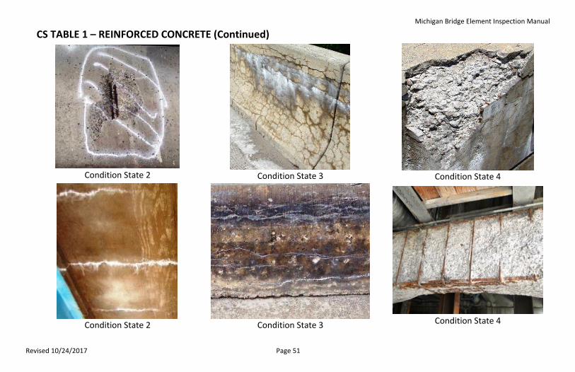
CS TABLE 1 – REINFORCED CONCRETE
Defect Condition State 1 Condition State 2 Condition State 3 Condition State 4 GOOD FAIR POOR SEVERE
Spalls/ Delaminations/ Patch Areas (1080)
None. Delaminated. Spall 1 in. or less deep or less than 6 in. diameter. Patched area is sound.
Spall greater than 1 in. deep or greater than 6 in. diameter. Patched area is unsound or showing distress. Does not warrant structural review.
The condition warrants a structural review to determine the effect on strength or serviceability of the element or bridge; OR a structural review has been completed and the defects impact strength or serviceability of the element or bridge.
Exposed Rebar (1090)
None. Present without section loss. Present with section loss that does not warrant structural review.
Efflorescence / Rust Staining (1120)
None. Surface white without build-up or leaching without rust staining.
Heavy build-up with rust staining.
Cracking (1) Reinforced Concrete and Other (1130)
Insignificant cracks or moderate-width cracks that have been sealed.
Unsealed moderate-width cracks or unsealed moderate pattern (map) cracking.
Wide cracks or heavy pattern (map) cracking.
Abrasion /Wear (1190)
No Abrasion of wearing Abrasion or wearing has exposed coarse aggregate
Coarse aggregate is loose or has popped out of the concrete matrix due to abrasion or wear.
Distortion – Culvert (1900)
None. Distortion not requiring mitigation or mitigated distortion.
Distortion that requires mitigation but does not require structural review.
Settlement – Substructure Elements (4000)
None. Exists within tolerable limits or arrested with effective actions taken to mitigate.
Exceeds tolerable limits but does not warrant structural review.
Michigan Bridge Element Inspection Manual
Revised 10/24/2017 Page 50
CS TABLE 1 – REINFORCED CONCRETE (Continued) Scour - Substructure / Culvert Elements (6000)
None. Exists within tolerable limits or arrested with effective countermeasures.
Exceeds tolerable limits but is less than the limits determined by scour evaluation, and does not warrant structural review.
Damage (7000)
Not applicable. The element has minor damage caused by vehicular or vessel impact.
The element has moderate damage caused by vehicular or vessel impact.
The element has severe damage caused by vehicular or vessel impact.
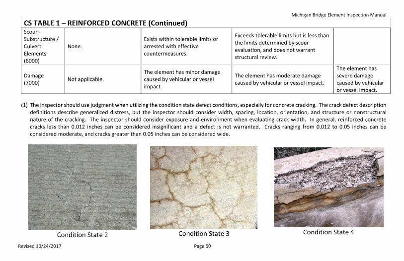
(1) The inspector should use judgment when utilizing the condition state defect conditions, especially for concrete cracking. The crack defect description
definitions describe generalized distress, but the inspector should consider width, spacing, location, orientation, and structure or nonstructural nature of the cracking. The inspector should consider exposure and environment when evaluating crack width. In general, reinforced concrete cracks less than 0.012 inches can be considered insignificant and a defect is not warranted. Cracks ranging from 0.012 to 0.05 inches can be considered moderate, and cracks greater than 0.05 inches can be considered wide.
Condition State 2
Condition State 3
Condition State 4
Michigan Bridge Element Inspection Manual
Revised 10/24/2017 Page 51
CS TABLE 1 – REINFORCED CONCRETE (Continued)
Condition State 2
Condition State 3
Condition State 4
Condition State 2
Condition State 3
Condition State 4
Michigan Bridge Element Inspection Manual
Revised 10/24/2017 Page 52
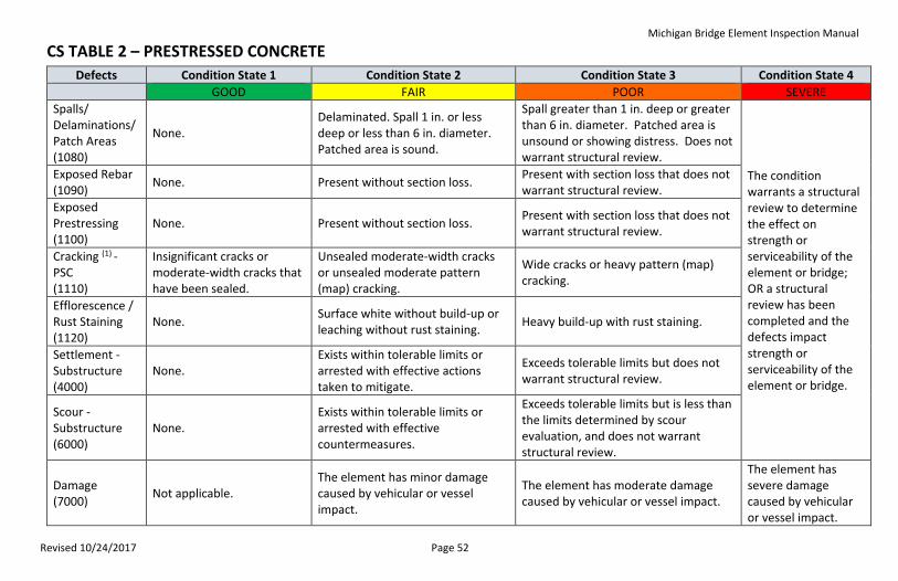
CS TABLE 2 – PRESTRESSED CONCRETE
Defects Condition State 1 Condition State 2 Condition State 3 Condition State 4
GOOD FAIR POOR SEVERE
Spalls/ Delaminations/ Patch Areas (1080)
None. Delaminated. Spall 1 in. or less deep or less than 6 in. diameter. Patched area is sound.
Spall greater than 1 in. deep or greater than 6 in. diameter. Patched area is unsound or showing distress. Does not warrant structural review.
The condition warrants a structural review to determine the effect on strength or serviceability of the element or bridge; OR a structural review has been completed and the defects impact strength or serviceability of the element or bridge.
Exposed Rebar (1090)
None. Present without section loss. Present with section loss that does not warrant structural review.
Exposed Prestressing (1100)
None. Present without section loss. Present with section loss that does not warrant structural review.
Cracking (1) - PSC (1110)
Insignificant cracks or moderate-width cracks that have been sealed.
Unsealed moderate-width cracks or unsealed moderate pattern (map) cracking.
Wide cracks or heavy pattern (map) cracking.
Efflorescence / Rust Staining (1120)
None. Surface white without build-up or leaching without rust staining.
Heavy build-up with rust staining.
Settlement - Substructure (4000)
None. Exists within tolerable limits or arrested with effective actions taken to mitigate.
Exceeds tolerable limits but does not warrant structural review.
Scour - Substructure (6000)
None. Exists within tolerable limits or arrested with effective countermeasures.
Exceeds tolerable limits but is less than the limits determined by scour evaluation, and does not warrant structural review.
Damage (7000)
Not applicable. The element has minor damage caused by vehicular or vessel impact.
The element has moderate damage caused by vehicular or vessel impact.
The element has severe damage caused by vehicular or vessel impact.
Michigan Bridge Element Inspection Manual
Revised 10/24/2017 Page 53
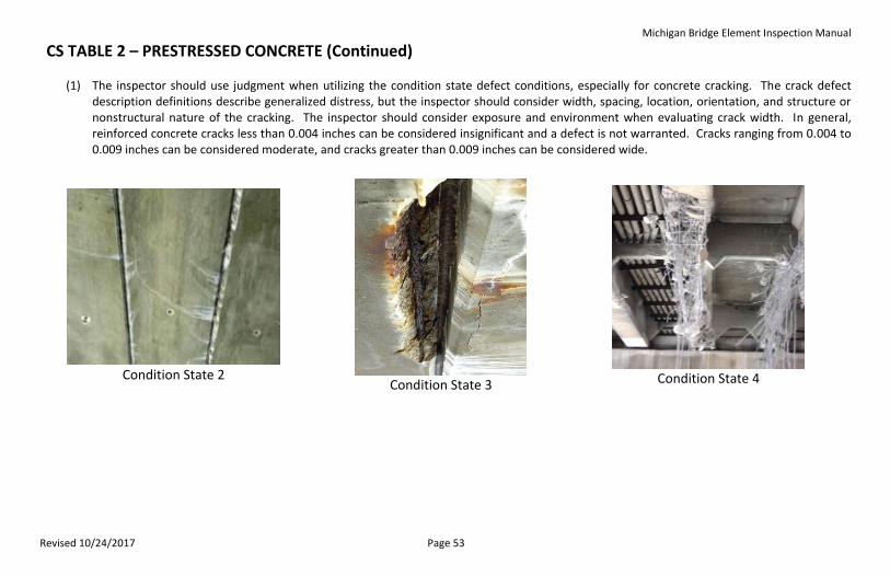
CS TABLE 2 – PRESTRESSED CONCRETE (Continued)
(1) The inspector should use judgment when utilizing the condition state defect conditions, especially for concrete cracking. The crack defect
description definitions describe generalized distress, but the inspector should consider width, spacing, location, orientation, and structure or nonstructural nature of the cracking. The inspector should consider exposure and environment when evaluating crack width. In general, reinforced concrete cracks less than 0.004 inches can be considered insignificant and a defect is not warranted. Cracks ranging from 0.004 to 0.009 inches can be considered moderate, and cracks greater than 0.009 inches can be considered wide.
Condition State 2
Condition State 3
Condition State 4
Michigan Bridge Element Inspection Manual
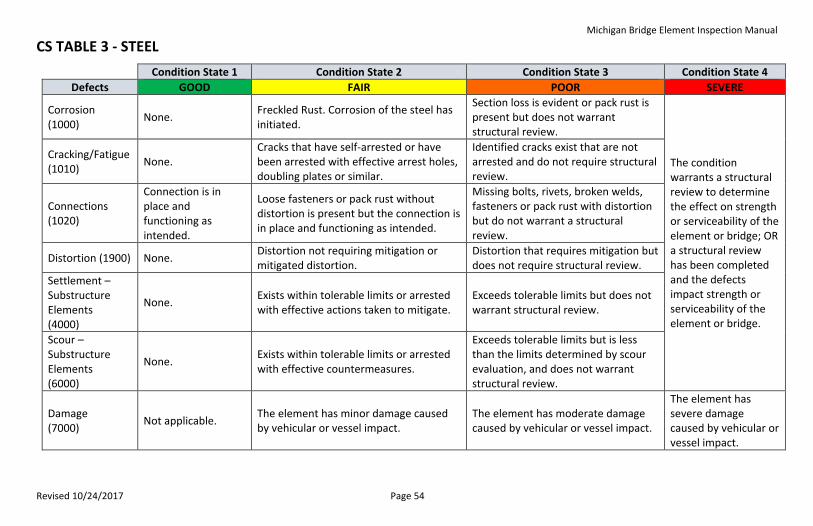
Revised 10/24/2017 Page 54
CS TABLE 3 - STEEL
Condition State 1 Condition State 2 Condition State 3 Condition State 4
Defects GOOD FAIR POOR SEVERE
Corrosion (1000)
None. Freckled Rust. Corrosion of the steel has initiated.
Section loss is evident or pack rust is present but does not warrant structural review.
The condition warrants a structural review to determine the effect on strength or serviceability of the element or bridge; OR a structural review has been completed and the defects impact strength or serviceability of the element or bridge.
Cracking/Fatigue (1010)
None. Cracks that have self-arrested or have been arrested with effective arrest holes, doubling plates or similar.
Identified cracks exist that are not arrested and do not require structural review.
Connections (1020)
Connection is in place and functioning as intended.
Loose fasteners or pack rust without distortion is present but the connection is in place and functioning as intended.
Missing bolts, rivets, broken welds, fasteners or pack rust with distortion but do not warrant a structural review.
Distortion (1900) None. Distortion not requiring mitigation or mitigated distortion.
Distortion that requires mitigation but does not require structural review.
Settlement – Substructure Elements (4000)
None. Exists within tolerable limits or arrested with effective actions taken to mitigate.
Exceeds tolerable limits but does not warrant structural review.
Scour – Substructure Elements (6000)
None. Exists within tolerable limits or arrested with effective countermeasures.
Exceeds tolerable limits but is less than the limits determined by scour evaluation, and does not warrant structural review.
Damage (7000)
Not applicable. The element has minor damage caused by vehicular or vessel impact.
The element has moderate damage caused by vehicular or vessel impact.
The element has severe damage caused by vehicular or vessel impact.
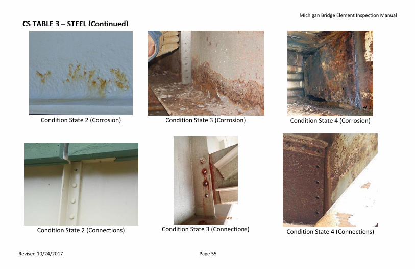
Michigan Bridge Element Inspection Manual
Revised 10/24/2017 Page 55
CS TABLE 3 – STEEL (Continued)
Condition State 2 (Corrosion)
Condition State 3 (Corrosion)
Condition State 4 (Corrosion)
Condition State 2 (Connections)
Condition State 3 (Connections)
Condition State 4 (Connections)
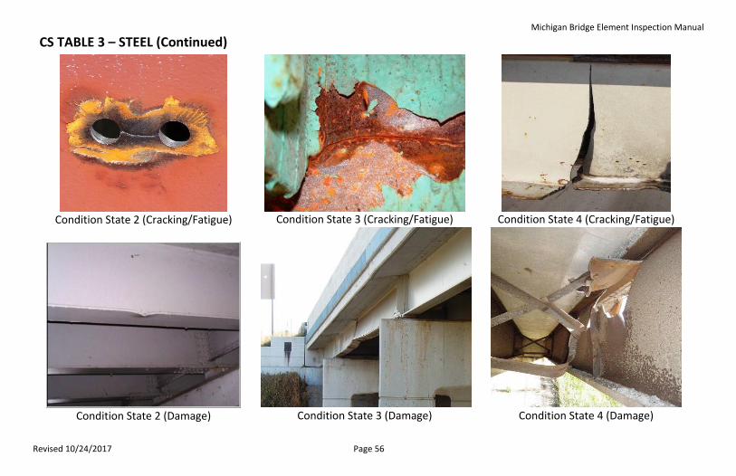
Michigan Bridge Element Inspection Manual
Revised 10/24/2017 Page 56
CS TABLE 3 – STEEL (Continued)
Condition State 2 (Cracking/Fatigue)
Condition State 3 (Cracking/Fatigue)
Condition State 4 (Cracking/Fatigue)
Condition State 2 (Damage)
Condition State 3 (Damage)
Condition State 4 (Damage)
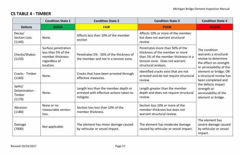
Michigan Bridge Element Inspection Manual
Revised 10/24/2017 Page 57
CS TABLE 4 - TIMBER
Condition State 1 Condition State 2 Condition State 3 Condition State 4
Defects GOOD FAIR POOR SEVERE
Decay/ Section Loss (1140)
None. Affects less than 10% of the member section
Affects 10% or more of the member but does not warrant structural review.
The condition warrants a structural review to determine the effect on strength or serviceability of the element or bridge; OR a structural review has been completed and the defects impact strength or serviceability of the element or bridge.
Checks/Shakes (1150)
Surface penetration less than 5% of the member thickness regardless of location.
Penetrates 5% - 50% of the thickness of the member and not in a tension zone.
Penetrates more than 50% of the thickness of the member or more than 5% of the member thickness in a tension zone. Does not warrant structural analysis.
Cracks - Timber (1160)
None. Cracks that have been arrested through effective measures.
Identified cracks exist that are not arrested and do not require structural review.
Splits/ Delamination - Timber (1170)
None. Length less than the member depth or arrested with effective actions taken to mitigate.
Length greater than the member depth and does not require structural review.
Abrasion (1180)
None or no measurable section loss.
Section loss less than 10% of the member thickness.
Section loss 10% or more of the member thickness but does not warrant structural review.
Damage (7000)
Not applicable. The element has minor damage caused by vehicular or vessel impact.
The element has moderate damage caused by vehicular or vessel impact.
The element has severe damage caused by vehicular or vessel impact.
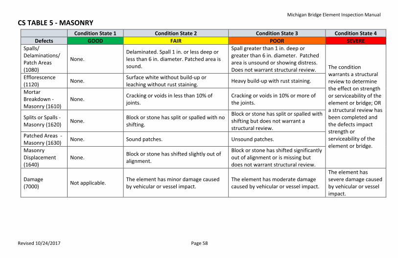
Michigan Bridge Element Inspection Manual
Revised 10/24/2017 Page 58
CS TABLE 5 - MASONRY
Condition State 1 Condition State 2 Condition State 3 Condition State 4
Defects GOOD FAIR POOR SEVERE
Spalls/ Delaminations/ Patch Areas (1080)
None. Delaminated. Spall 1 in. or less deep or less than 6 in. diameter. Patched area is sound.
Spall greater than 1 in. deep or greater than 6 in. diameter. Patched area is unsound or showing distress. Does not warrant structural review. The condition
warrants a structural review to determine the effect on strength or serviceability of the element or bridge; OR a structural review has been completed and the defects impact strength or serviceability of the element or bridge.
Efflorescence (1120)
None. Surface white without build-up or leaching without rust staining.
Heavy build-up with rust staining.
Mortar Breakdown - Masonry (1610)
None. Cracking or voids in less than 10% of joints.
Cracking or voids in 10% or more of the joints.
Splits or Spalls - Masonry (1620)
None. Block or stone has split or spalled with no shifting.
Block or stone has split or spalled with shifting but does not warrant a structural review.
Patched Areas -Masonry (1630)
None. Sound patches. Unsound patches.
Masonry Displacement (1640)
None. Block or stone has shifted slightly out of alignment.
Block or stone has shifted significantly out of alignment or is missing but does not warrant structural review.
Damage (7000)
Not applicable. The element has minor damage caused by vehicular or vessel impact.
The element has moderate damage caused by vehicular or vessel impact.
The element has severe damage caused by vehicular or vessel impact.
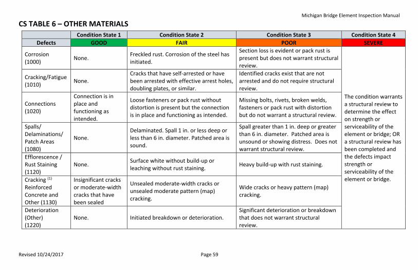
Michigan Bridge Element Inspection Manual
Revised 10/24/2017 Page 59
CS TABLE 6 – OTHER MATERIALS
Condition State 1 Condition State 2 Condition State 3 Condition State 4
Defects GOOD FAIR POOR SEVERE
Corrosion (1000)
None. Freckled rust. Corrosion of the steel has initiated.
Section loss is evident or pack rust is present but does not warrant structural review.
The condition warrants a structural review to determine the effect on strength or serviceability of the element or bridge; OR a structural review has been completed and the defects impact strength or serviceability of the element or bridge.
Cracking/Fatigue (1010)
None. Cracks that have self-arrested or have been arrested with effective arrest holes, doubling plates, or similar.
Identified cracks exist that are not arrested and do not require structural review.
Connections (1020)
Connection is in place and functioning as intended.
Loose fasteners or pack rust without distortion is present but the connection is in place and functioning as intended.
Missing bolts, rivets, broken welds, fasteners or pack rust with distortion but do not warrant a structural review.
Spalls/ Delaminations/ Patch Areas (1080)
None. Delaminated. Spall 1 in. or less deep or less than 6 in. diameter. Patched area is sound.
Spall greater than 1 in. deep or greater than 6 in. diameter. Patched area is unsound or showing distress. Does not warrant structural review.
Efflorescence / Rust Staining (1120)
None. Surface white without build-up or leaching without rust staining.
Heavy build-up with rust staining.
Cracking (1) Reinforced Concrete and Other (1130)
Insignificant cracks or moderate-width cracks that have been sealed
Unsealed moderate-width cracks or unsealed moderate pattern (map) cracking.
Wide cracks or heavy pattern (map) cracking.
Deterioration (Other) (1220)
None. Initiated breakdown or deterioration. Significant deterioration or breakdown that does not warrant structural review.
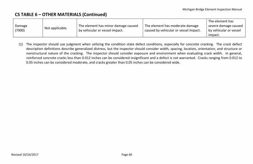
Michigan Bridge Element Inspection Manual
Revised 10/24/2017 Page 60
CS TABLE 6 – OTHER MATERIALS (Continued)
Damage (7000)
Not applicable. The element has minor damage caused by vehicular or vessel impact.
The element has moderate damage caused by vehicular or vessel impact.
The element has severe damage caused by vehicular or vessel impact.
(1) The inspector should use judgment when utilizing the condition state defect conditions, especially for concrete cracking. The crack defect
description definitions describe generalized distress, but the inspector should consider width, spacing, location, orientation, and structure or nonstructural nature of the cracking. The inspector should consider exposure and environment when evaluating crack width. In general, reinforced concrete cracks less than 0.012 inches can be considered insignificant and a defect is not warranted. Cracks ranging from 0.012 to 0.05 inches can be considered moderate, and cracks greater than 0.05 inches can be considered wide.
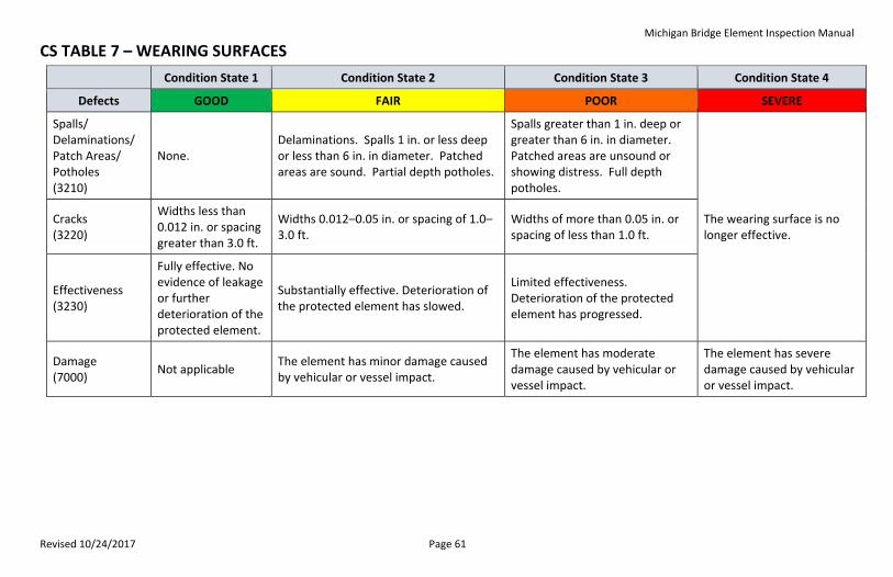
Michigan Bridge Element Inspection Manual
Revised 10/24/2017 Page 61
CS TABLE 7 – WEARING SURFACES
Condition State 1 Condition State 2 Condition State 3 Condition State 4
Defects GOOD FAIR POOR SEVERE
Spalls/ Delaminations/ Patch Areas/ Potholes (3210)
None. Delaminations. Spalls 1 in. or less deep or less than 6 in. in diameter. Patched areas are sound. Partial depth potholes.
Spalls greater than 1 in. deep or greater than 6 in. in diameter. Patched areas are unsound or showing distress. Full depth potholes.
The wearing surface is no longer effective.
Cracks (3220)
Widths less than 0.012 in. or spacing greater than 3.0 ft.
Widths 0.012–0.05 in. or spacing of 1.0–3.0 ft.
Widths of more than 0.05 in. or spacing of less than 1.0 ft.
Effectiveness (3230)
Fully effective. No evidence of leakage or further deterioration of the protected element.
Substantially effective. Deterioration of the protected element has slowed.
Limited effectiveness. Deterioration of the protected element has progressed.
Damage (7000)
Not applicable The element has minor damage caused by vehicular or vessel impact.
The element has moderate damage caused by vehicular or vessel impact.
The element has severe damage caused by vehicular or vessel impact.
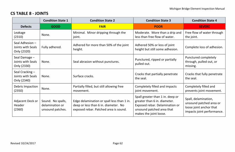
Michigan Bridge Element Inspection Manual
Revised 10/24/2017 Page 62
CS TABLE 8 - JOINTS
Condition State 1 Condition State 2 Condition State 3 Condition State 4
Defects GOOD FAIR POOR SEVERE
Leakage (2310)
None. Minimal. Minor dripping through the joint.
Moderate. More than a drip and less than free flow of water.
Free flow of water through the joint.
Seal Adhesion – Joints with Seals Only (2320)
Fully adhered. Adhered for more than 50% of the joint height.
Adhered 50% or less of joint height but still some adhesion.
Complete loss of adhesion.
Seal Damage – Joints with Seals Only (2330)
None. Seal abrasion without punctures. Punctured, ripped or partially pulled out.
Punctured completely through, pulled out, or missing.
Seal Cracking – Joints with Seals Only (2340)
None. Surface cracks. Cracks that partially penetrate the seal.
Cracks that fully penetrate the seal.
Debris Impaction (2350)
None. Partially filled, but still allowing free movement.
Completely filled and impacts joint movement.
Completely filled and prevents joint movement.
Adjacent Deck or Header (2360)
Sound. No spalls, delamination or unsound patches.
Edge delamination or spall less than 1 in. deep or less than 6 in. diameter. No exposed rebar. Patched area is sound.
Spall greater than 1 in. deep or greater than 6 in. diameter. Exposed rebar. Delamination or unsound patched area that makes the joint loose.
Spall, delamination, unsound patched area or loose joint anchor that impacts joint performance.
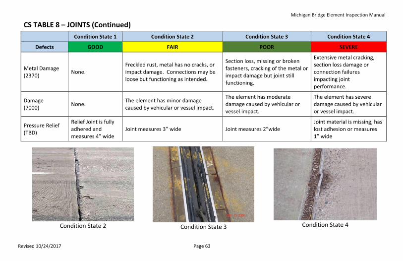
Michigan Bridge Element Inspection Manual
Revised 10/24/2017 Page 63
CS TABLE 8 – JOINTS (Continued)
Condition State 1 Condition State 2 Condition State 3 Condition State 4
Defects GOOD FAIR POOR SEVERE
Metal Damage (2370)
None. Freckled rust, metal has no cracks, or impact damage. Connections may be loose but functioning as intended.
Section loss, missing or broken fasteners, cracking of the metal or impact damage but joint still functioning.
Extensive metal cracking, section loss damage or connection failures impacting joint performance.
Damage (7000)
None. The element has minor damage caused by vehicular or vessel impact.
The element has moderate damage caused by vehicular or vessel impact.
The element has severe damage caused by vehicular or vessel impact.
Pressure Relief (TBD)
Relief Joint is fully adhered and measures 4” wide
Joint measures 3” wide Joint measures 2”wide Joint material is missing, has lost adhesion or measures 1” wide
Condition State 2
Condition State 3
Condition State 4
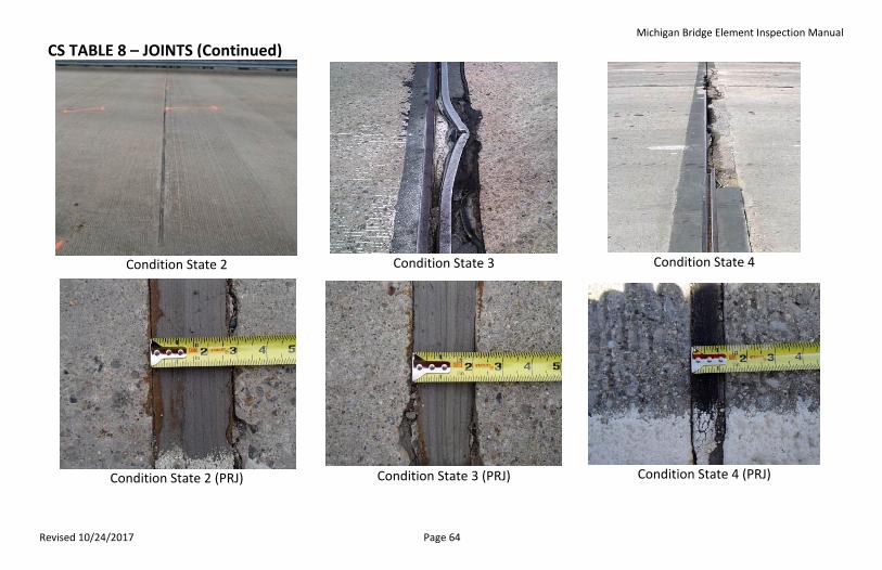
Michigan Bridge Element Inspection Manual
Revised 10/24/2017 Page 64
CS TABLE 8 – JOINTS (Continued)
Condition State 2
Condition State 3
Condition State 4
Condition State 2 (PRJ)
Condition State 3 (PRJ)
Condition State 4 (PRJ)
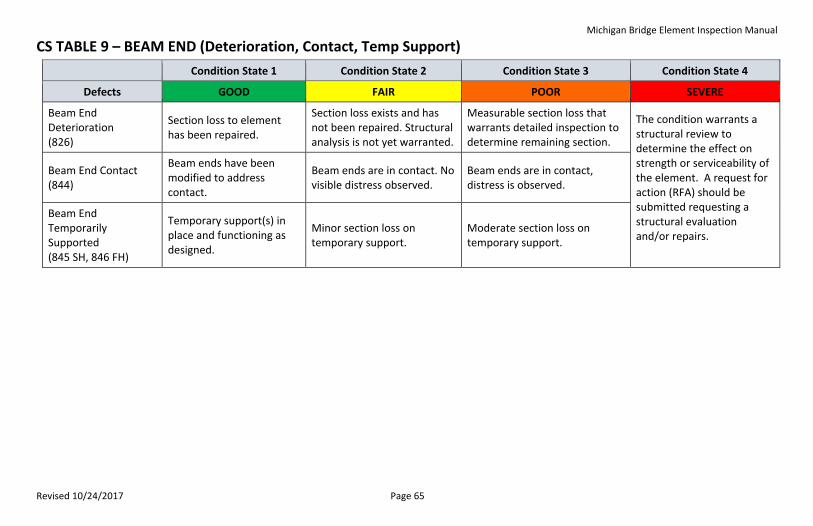
Michigan Bridge Element Inspection Manual
Revised 10/24/2017 Page 65
CS TABLE 9 – BEAM END (Deterioration, Contact, Temp Support)
Condition State 1 Condition State 2 Condition State 3 Condition State 4
Defects GOOD FAIR POOR SEVERE
Beam End Deterioration (826)
Section loss to element has been repaired.
Section loss exists and has not been repaired. Structural analysis is not yet warranted.
Measurable section loss that warrants detailed inspection to determine remaining section.
The condition warrants a structural review to determine the effect on strength or serviceability of the element. A request for action (RFA) should be submitted requesting a structural evaluation and/or repairs.
Beam End Contact (844)
Beam ends have been modified to address contact.
Beam ends are in contact. No visible distress observed.
Beam ends are in contact, distress is observed.
Beam End Temporarily Supported (845 SH, 846 FH)
Temporary support(s) in place and functioning as designed.
Minor section loss on temporary support.
Moderate section loss on temporary support.
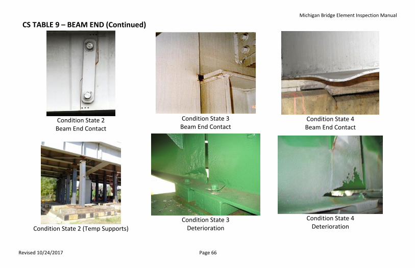
Michigan Bridge Element Inspection Manual
Revised 10/24/2017 Page 66
CS TABLE 9 – BEAM END (Continued)
Condition State 2 Beam End Contact
Condition State 3 Beam End Contact
Condition State 4 Beam End Contact
Condition State 2 (Temp Supports)
Condition State 3
Deterioration
Condition State 4
Deterioration
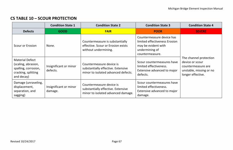
Michigan Bridge Element Inspection Manual
Revised 10/24/2017 Page 67
CS TABLE 10 – SCOUR PROTECTION
Condition State 1 Condition State 2 Condition State 3 Condition State 4
Defects GOOD FAIR POOR SEVERE
Scour or Erosion None. Countermeasure is substantially effective. Scour or Erosion exists without undermining.
Countermeasure device has limited effectiveness Erosion may be evident with undermining of countermeasure.
The channel protection device or scour countermeasure are unstable, missing or no longer effective.
Material Defect (scaling, abrasion, spalling, corrosion, cracking, splitting and decay)
Insignificant or minor defects.
Countermeasure device is substantially effective. Extensive minor to isolated advanced defects.
Scour countermeasures have limited effectiveness. Extensive advanced to major defects.
Damage (unraveling, displacement, separation, and sagging)
Insignificant or minor damage.
Countermeasure device is substantially effective. Extensive minor to isolated advanced damage.
Scour countermeasures have limited effectiveness. Extensive advanced to major damage.
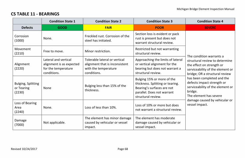
Michigan Bridge Element Inspection Manual
Revised 10/24/2017 Page 68
CS TABLE 11 - BEARINGS
Condition State 1 Condition State 2 Condition State 3 Condition State 4
Defects GOOD FAIR POOR SEVERE
Corrosion (1000)
None. Freckled rust. Corrosion of the steel has initiated.
Section loss is evident or pack rust is present but does not warrant structural review.
The condition warrants a structural review to determine the effect on strength or serviceability of the element or bridge; OR a structural review has been completed and the defects impact strength or serviceability of the element or bridge. The element has severe damage caused by vehicular or vessel impact.
Movement (2210)
Free to move. Minor restriction. Restricted but not warranting structural review.
Alignment (2220)
Lateral and vertical alignment is as expected for the temperature conditions.
Tolerable lateral or vertical alignment that is inconsistent with the temperature conditions.
Approaching the limits of lateral or vertical alignment for the bearing but does not warrant a structural review.
Bulging, Splitting or Tearing (2230)
None Bulging less than 15% of the thickness.
Bulging 15% or more of the thickness. Splitting or tearing. Bearing’s surfaces are not parallel. Does not warrant structural review.
Loss of Bearing Area (2240)
None. Loss of less than 10%. Loss of 10% or more but does not warrant a structural review.
Damage (7000)
Not applicable. The element has minor damage caused by vehicular or vessel impact.
The element has moderate damage caused by vehicular or vessel impact.
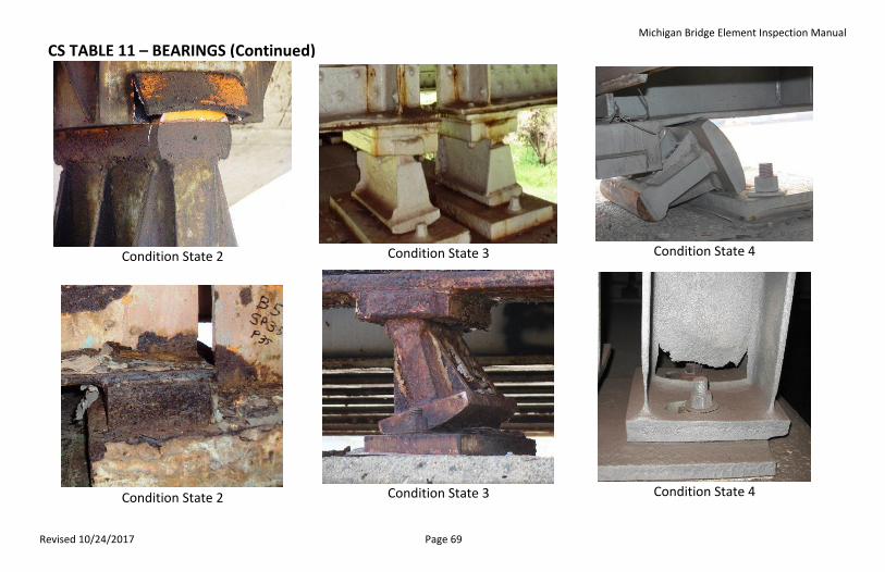
Michigan Bridge Element Inspection Manual
Revised 10/24/2017 Page 69
CS TABLE 11 – BEARINGS (Continued)
Condition State 2
Condition State 3
Condition State 4
Condition State 2
Condition State 3
Condition State 4
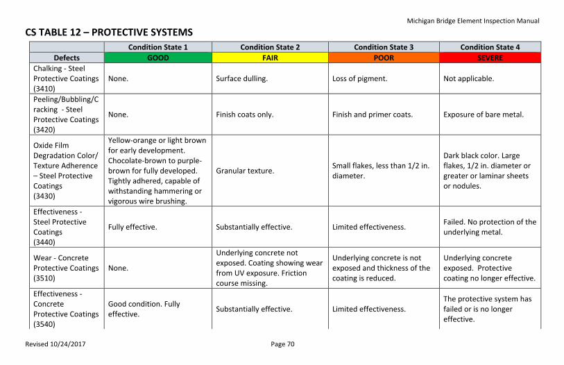
Michigan Bridge Element Inspection Manual
Revised 10/24/2017 Page 70
CS TABLE 12 – PROTECTIVE SYSTEMS
Condition State 1 Condition State 2 Condition State 3 Condition State 4
Defects GOOD FAIR POOR SEVERE
Chalking - Steel Protective Coatings (3410)
None. Surface dulling. Loss of pigment. Not applicable.
Peeling/Bubbling/Cracking - Steel Protective Coatings (3420)
None. Finish coats only. Finish and primer coats. Exposure of bare metal.
Oxide Film Degradation Color/ Texture Adherence – Steel Protective Coatings (3430)
Yellow-orange or light brown for early development. Chocolate-brown to purple-brown for fully developed. Tightly adhered, capable of withstanding hammering or vigorous wire brushing.
Granular texture. Small flakes, less than 1/2 in. diameter.
Dark black color. Large flakes, 1/2 in. diameter or greater or laminar sheets or nodules.
Effectiveness - Steel Protective Coatings (3440)
Fully effective. Substantially effective. Limited effectiveness. Failed. No protection of the underlying metal.
Wear - Concrete Protective Coatings (3510)
None.
Underlying concrete not exposed. Coating showing wear from UV exposure. Friction course missing.
Underlying concrete is not exposed and thickness of the coating is reduced.
Underlying concrete exposed. Protective coating no longer effective.
Effectiveness - Concrete Protective Coatings (3540)
Good condition. Fully effective.
Substantially effective. Limited effectiveness. The protective system has failed or is no longer effective.
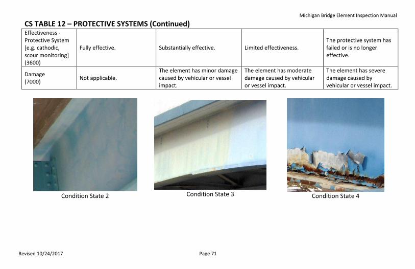
Michigan Bridge Element Inspection Manual
Revised 10/24/2017 Page 71
CS TABLE 12 – PROTECTIVE SYSTEMS (Continued) Effectiveness - Protective System [e.g. cathodic, scour monitoring] (3600)
Fully effective. Substantially effective. Limited effectiveness. The protective system has failed or is no longer effective.
Damage (7000)
Not applicable. The element has minor damage caused by vehicular or vessel impact.
The element has moderate damage caused by vehicular or vessel impact.
The element has severe damage caused by vehicular or vessel impact.
Condition State 2
Condition State 3
Condition State 4
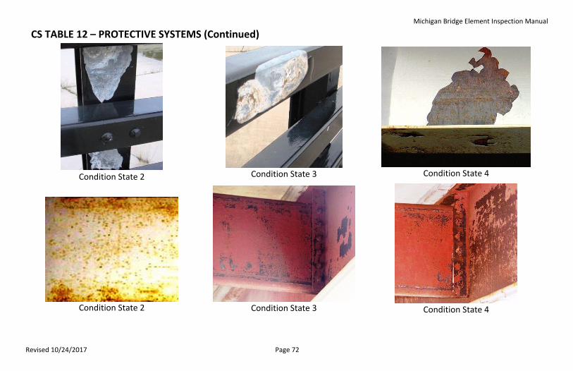
Michigan Bridge Element Inspection Manual
Revised 10/24/2017 Page 72
CS TABLE 12 – PROTECTIVE SYSTEMS (Continued)
Condition State 2
Condition State 3
Condition State 4
Condition State 2
Condition State 3
Condition State 4
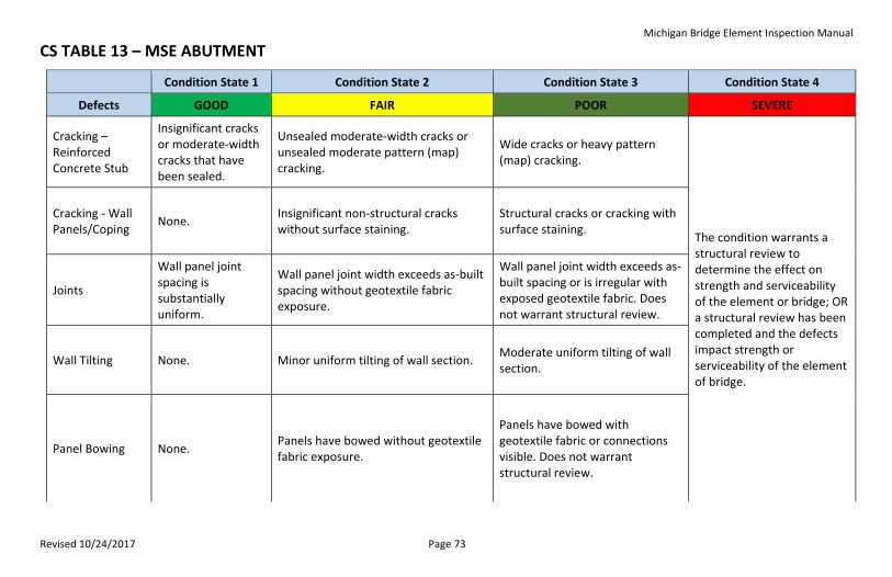
Michigan Bridge Element Inspection Manual
Revised 10/24/2017 Page 73
CS TABLE 13 – MSE ABUTMENT
Condition State 1 Condition State 2 Condition State 3 Condition State 4
Defects GOOD FAIR POOR SEVERE
Cracking – Reinforced Concrete Stub
Insignificant cracks or moderate-width cracks that have been sealed.
Unsealed moderate-width cracks or unsealed moderate pattern (map) cracking.
Wide cracks or heavy pattern (map) cracking.
The condition warrants a structural review to determine the effect on strength and serviceability of the element or bridge; OR a structural review has been completed and the defects impact strength or serviceability of the element of bridge.
Cracking - Wall Panels/Coping
None. Insignificant non-structural cracks without surface staining.
Structural cracks or cracking with surface staining.
Joints
Wall panel joint spacing is substantially uniform.
Wall panel joint width exceeds as-built spacing without geotextile fabric exposure.
Wall panel joint width exceeds as-built spacing or is irregular with exposed geotextile fabric. Does not warrant structural review.
Wall Tilting None. Minor uniform tilting of wall section. Moderate uniform tilting of wall section.
Panel Bowing None. Panels have bowed without geotextile fabric exposure.
Panels have bowed with geotextile fabric or connections visible. Does not warrant structural review.
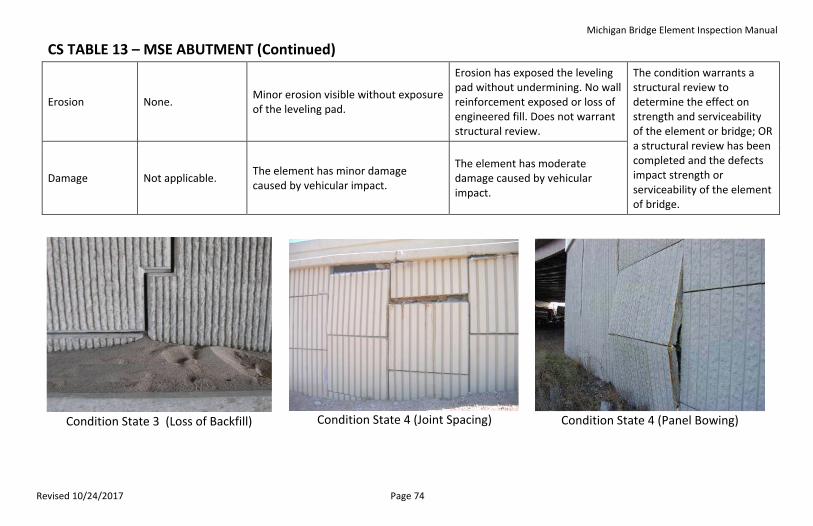
Michigan Bridge Element Inspection Manual
Revised 10/24/2017 Page 74
CS TABLE 13 – MSE ABUTMENT (Continued)
Erosion None. Minor erosion visible without exposure of the leveling pad.
Erosion has exposed the leveling pad without undermining. No wall reinforcement exposed or loss of engineered fill. Does not warrant structural review.
The condition warrants a structural review to determine the effect on strength and serviceability of the element or bridge; OR a structural review has been completed and the defects impact strength or serviceability of the element of bridge.
Damage Not applicable. The element has minor damage caused by vehicular impact.
The element has moderate damage caused by vehicular impact.
Condition State 3 (Loss of Backfill)
Condition State 4 (Joint Spacing)
Condition State 4 (Panel Bowing)
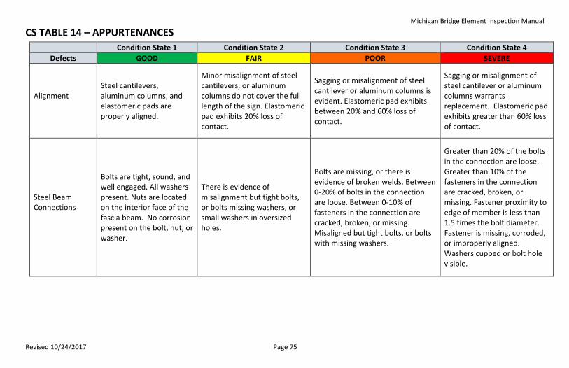
Michigan Bridge Element Inspection Manual
Revised 10/24/2017 Page 75
CS TABLE 14 – APPURTENANCES
Condition State 1 Condition State 2 Condition State 3 Condition State 4
Defects GOOD FAIR POOR SEVERE
Alignment
Steel cantilevers, aluminum columns, and elastomeric pads are properly aligned.
Minor misalignment of steel cantilevers, or aluminum columns do not cover the full length of the sign. Elastomeric pad exhibits 20% loss of contact.
Sagging or misalignment of steel cantilever or aluminum columns is evident. Elastomeric pad exhibits between 20% and 60% loss of contact.
Sagging or misalignment of steel cantilever or aluminum columns warrants replacement. Elastomeric pad exhibits greater than 60% loss of contact.
Steel Beam Connections
Bolts are tight, sound, and well engaged. All washers present. Nuts are located on the interior face of the fascia beam. No corrosion present on the bolt, nut, or washer.
There is evidence of misalignment but tight bolts, or bolts missing washers, or small washers in oversized holes.
Bolts are missing, or there is evidence of broken welds. Between 0-20% of bolts in the connection are loose. Between 0-10% of fasteners in the connection are cracked, broken, or missing. Misaligned but tight bolts, or bolts with missing washers.
Greater than 20% of the bolts in the connection are loose. Greater than 10% of the fasteners in the connection are cracked, broken, or missing. Fastener proximity to edge of member is less than 1.5 times the bolt diameter. Fastener is missing, corroded, or improperly aligned. Washers cupped or bolt hole visible.
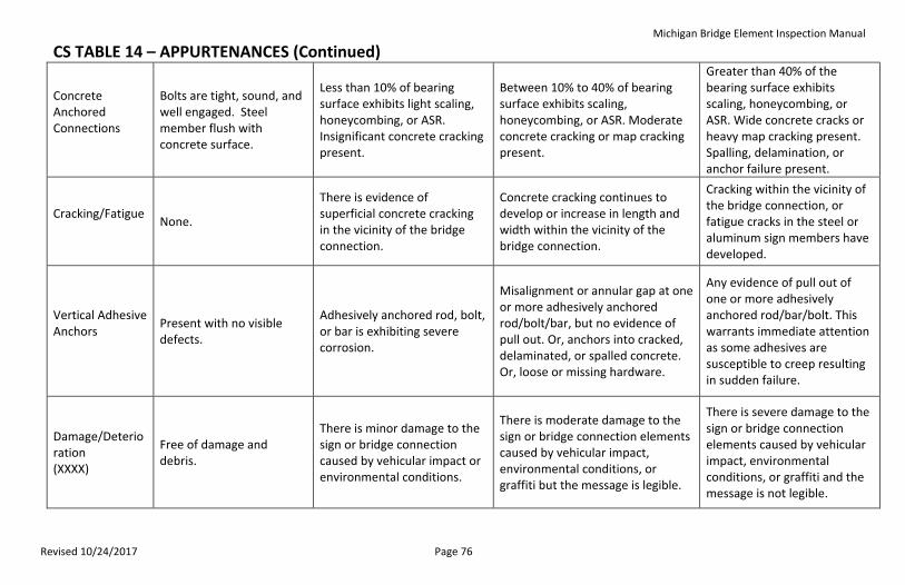
Michigan Bridge Element Inspection Manual
Revised 10/24/2017 Page 76
CS TABLE 14 – APPURTENANCES (Continued)
Concrete Anchored Connections
Bolts are tight, sound, and well engaged. Steel member flush with concrete surface.
Less than 10% of bearing surface exhibits light scaling, honeycombing, or ASR. Insignificant concrete cracking present.
Between 10% to 40% of bearing surface exhibits scaling, honeycombing, or ASR. Moderate concrete cracking or map cracking present.
Greater than 40% of the bearing surface exhibits scaling, honeycombing, or ASR. Wide concrete cracks or heavy map cracking present. Spalling, delamination, or anchor failure present.
Cracking/Fatigue
None.
There is evidence of superficial concrete cracking in the vicinity of the bridge connection.
Concrete cracking continues to develop or increase in length and width within the vicinity of the bridge connection.
Cracking within the vicinity of the bridge connection, or fatigue cracks in the steel or aluminum sign members have developed.
Vertical Adhesive Anchors
Present with no visible defects.
Adhesively anchored rod, bolt, or bar is exhibiting severe corrosion.
Misalignment or annular gap at one or more adhesively anchored rod/bolt/bar, but no evidence of pull out. Or, anchors into cracked, delaminated, or spalled concrete. Or, loose or missing hardware.
Any evidence of pull out of one or more adhesively anchored rod/bar/bolt. This warrants immediate attention as some adhesives are susceptible to creep resulting in sudden failure.
Damage/Deterioration (XXXX)
Free of damage and debris.
There is minor damage to the sign or bridge connection caused by vehicular impact or environmental conditions.
There is moderate damage to the sign or bridge connection elements caused by vehicular impact, environmental conditions, or graffiti but the message is legible.
There is severe damage to the sign or bridge connection elements caused by vehicular impact, environmental conditions, or graffiti and the message is not legible.
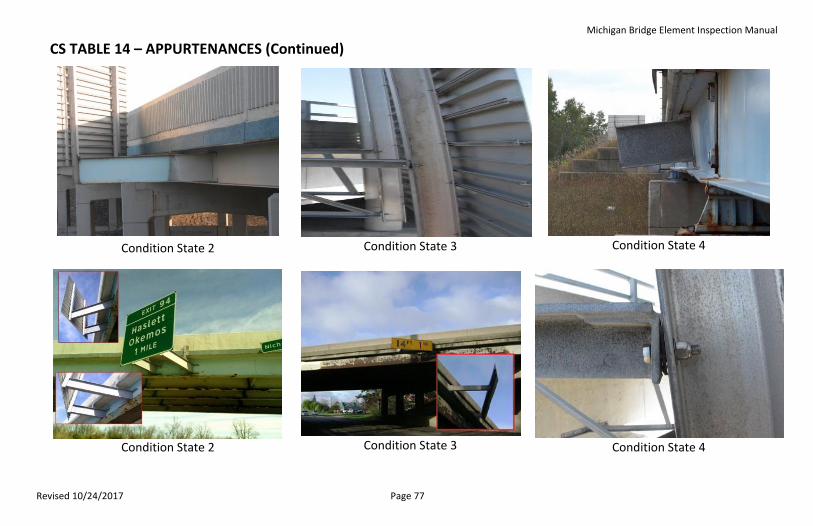
Michigan Bridge Element Inspection Manual
Revised 10/24/2017 Page 77
CS TABLE 14 – APPURTENANCES (Continued)
Condition State 2
Condition State 3
Condition State 4
Condition State 2
Condition State 3
Condition State 4
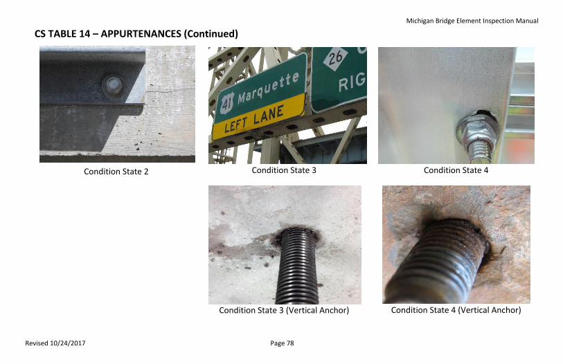
Michigan Bridge Element Inspection Manual
Revised 10/24/2017 Page 78
CS TABLE 14 – APPURTENANCES (Continued)
Condition State 2
Condition State 3
Condition State 4
Condition State 3 (Vertical Anchor)
Condition State 4 (Vertical Anchor)