BOS SG BIPV Recommendations v1.0 20140422
34
Balance of System Steering Group BIPV Recommendations 22 nd April 2014
-
Upload
kevin-mcintyre -
Category
Documents
-
view
42 -
download
1
Transcript of BOS SG BIPV Recommendations v1.0 20140422

Balance of System Steering Group
BIPV Recommendations
22nd April 2014

BoS SG BIPV Recommendations
BOS SG BIPV Recommendations v1.0 20140422 Page 2 of 34
Contributors .................................................................................................................................. 3
Executive Summary ....................................................................................................................... 4
Introduction to BIPV ...................................................................................................................... 6
Example of BIPV in a High-Rise Commercial Building ..................................................................... 7
Building Background ...................................................................................................................... 8
Challenges for BIPV Applications ................................................................................................. 10
Glazing Performance ................................................................................................................... 11
Shading ....................................................................................................................................... 12 Direct light versus diffused light ....................................................................................................................... 12
AC/DC Configurations .................................................................................................................. 13 Central inverters ............................................................................................................................................... 14 AC micro-inverters and DC optimizers ............................................................................................................. 14 String inverters ................................................................................................................................................. 15
Electrical Connection options for BIPV Modules within a Façade ................................................. 16 PV connectors and junction boxes ................................................................................................................... 16 Vertical stringing within a stick system ............................................................................................................ 19 Increasing the width of the thermal break ....................................................................................................... 20 Offsetting IGU glass within the façade ............................................................................................................ 22 Running cables at the bottom of the façade frame .......................................................................................... 22 Running cables in the top or side of the façade frame ..................................................................................... 23 Running cables within the façade back box ...................................................................................................... 23 Cabling under the face cap ............................................................................................................................... 23 Cabling within a structural glazing façade ........................................................................................................ 25 Internal cabling................................................................................................................................................. 26 Connecting a BIPV module ............................................................................................................................... 27 Summary of BIPV cabling options ..................................................................................................................... 28
IGU Replacement and Maintenance ............................................................................................ 29
Glass Safety ................................................................................................................................. 31
Nickel Sulphide inclusions ................................................................................................................................ 31 Thermal shock .................................................................................................................................................. 31 Blast proof ........................................................................................................................................................ 32
Fire Safety Perceptions ................................................................................................................ 32
Construction Design and Management Regulations ..................................................................... 33

BoS SG BIPV Recommendations
BOS SG BIPV Recommendations v1.0 20140422 Page 3 of 34
Contributors
I would like to thank those who attended the Steering Group, and for the contributions made of time and experience.
Kevin Arthur (Oxford PV)
Martyn Berry (Enphase Energy)
Paul Boylin (SMA Solar Technology)
David Bushnell (Oxford PV)
Selwyn Corns (Multi-Contact)
Martin Cotterell (Sundog Energy and representing the National Solar Centre)
Leon Friend (Hueck)
Iain Garner (Tigo Energy)
Brian McAllister (Oxford PV)
Kevin McIntyre (SG Chair, Oxford PV)
Paul Meehan (Power-One)
Mark Ryder (SMA Solar Technology)
Francois Saugues (Multi-Contact)
Mark Taylor (Allies and Morrison)
Matthew Turner (AECOM)
Ant Wilson (AECOM)
Reviewers
Steve Pester, BRE/National Solar Centre
David Metcalfe, Centre for Window and Cladding Technology A special thank you to Rick Wheal of Arup, who guided us down the path of setting up the Steering Group.
BoS SG BIPV Recommendations
BOS SG BIPV Recommendations v1.0 20140422 Page 4 of 34
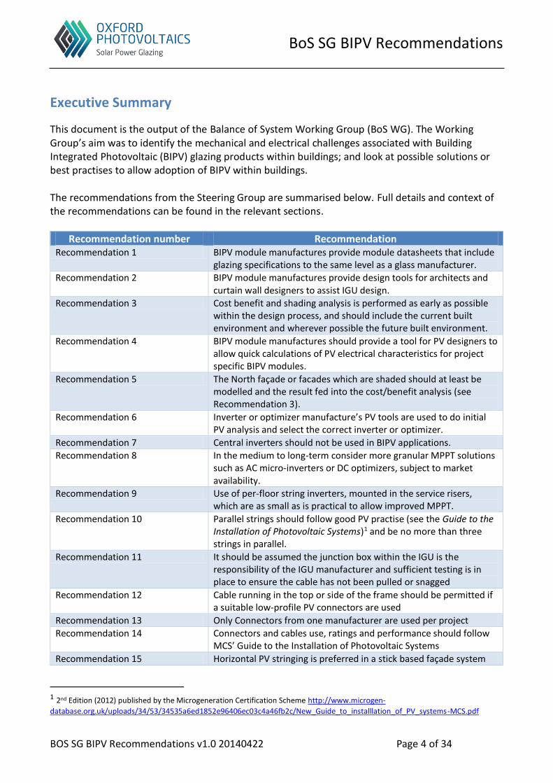
Executive Summary
This document is the output of the Balance of System Working Group (BoS WG). The Working Group’s aim was to identify the mechanical and electrical challenges associated with Building Integrated Photovoltaic (BIPV) glazing products within buildings; and look at possible solutions or best practises to allow adoption of BIPV within buildings. The recommendations from the Steering Group are summarised below. Full details and context of the recommendations can be found in the relevant sections.
Recommendation number Recommendation Recommendation 1 BIPV module manufactures provide module datasheets that include
glazing specifications to the same level as a glass manufacturer.
Recommendation 2 BIPV module manufactures provide design tools for architects and curtain wall designers to assist IGU design.
Recommendation 3 Cost benefit and shading analysis is performed as early as possible within the design process, and should include the current built environment and wherever possible the future built environment.
Recommendation 4 BIPV module manufactures should provide a tool for PV designers to allow quick calculations of PV electrical characteristics for project specific BIPV modules.
Recommendation 5 The North façade or facades which are shaded should at least be modelled and the result fed into the cost/benefit analysis (see Recommendation 3).
Recommendation 6 Inverter or optimizer manufacture’s PV tools are used to do initial PV analysis and select the correct inverter or optimizer.
Recommendation 7 Central inverters should not be used in BIPV applications.
Recommendation 8 In the medium to long-term consider more granular MPPT solutions such as AC micro-inverters or DC optimizers, subject to market availability.
Recommendation 9 Use of per-floor string inverters, mounted in the service risers, which are as small as is practical to allow improved MPPT.
Recommendation 10 Parallel strings should follow good PV practise (see the Guide to the Installation of Photovoltaic Systems)1 and be no more than three strings in parallel.
Recommendation 11 It should be assumed the junction box within the IGU is the responsibility of the IGU manufacturer and sufficient testing is in place to ensure the cable has not been pulled or snagged
Recommendation 12 Cable running in the top or side of the frame should be permitted if a suitable low-profile PV connectors are used
Recommendation 13 Only Connectors from one manufacturer are used per project
Recommendation 14 Connectors and cables use, ratings and performance should follow MCS’ Guide to the Installation of Photovoltaic Systems
Recommendation 15 Horizontal PV stringing is preferred in a stick based façade system
1 2nd Edition (2012) published by the Microgeneration Certification Scheme http://www.microgen-
database.org.uk/uploads/34/53/34535a6ed1852e96406ec03c4a46fb2c/New_Guide_to_installlation_of_PV_systems-MCS.pdf

BoS SG BIPV Recommendations
BOS SG BIPV Recommendations v1.0 20140422 Page 5 of 34
Recommendation number Recommendation Recommendation 16 The thermal break width is not increased to accommodate PV
cabling within the façade
Recommendation 17 That no IGU panes are offset from the edge of the frame to accommodate PV cabling
Recommendation 18 That PV cabling is not routed within the setting block channel or recess at the bottom of the IGU
Recommendation 19 Cable running in the top or side of the frame should be permitted if a suitable low-profile solutions is available
Recommendation 20 An anti-snagging option is considered on the façade to protect the solar cables prior to installation
Recommendation 21 For stick and unitised facades with cover caps the preferred connection for BIPV modules is utilising the space under the face or cover cap
Recommendation 22 For structural glazing, façade designers and fabricators need to consider how to protect PV cables from glazing tools when replacing an IGU.
Recommendation 23 For BIPV applications wiring is run around the edge of the floor to the service riser, with appropriately spaced floor plates allowing sufficient access to connectors. Avoid running cable through the middle of the floor
Recommendation 24 All cables are appropriately terminated prior to site installation with
touch safe connectors (see Table 4)
Recommendation 25 To speed up façade installation it is recommended that for each unitised façades that all cabling is done as part of the façade fabrication process; and likewise for stick systems as much is done as possible prior to installation
Recommendation 26 BIPV module covers are not required for the façade prior to installation, as touch-safe connectors should be used.
Recommendation 27 There should be sufficient slack in the cable to accommodate any joint movement the need to remove the IGU or glazing
Recommendation 28 BIPV modules from a glazing perspective should follow good industry best practise and the local building regulations
BoS SG BIPV Recommendations
BOS SG BIPV Recommendations v1.0 20140422 Page 6 of 34
Introduction to BIPV
Building Integrated PV (BIPV) is a photovoltaic material which is used as part of a construction product, and replaces a conventional construction product, for example replacing the roof, skylights or the façade of a building. The BIPV construction product (referred to here as BIPV module) has to perform all the functions expected of a building product, and is integral to the building fabric and building performance. Additionally, it is a PV product bringing all the benefits of PV to a building. In contrast a Building Applied Photovoltaic (BAPV) product is not integral to the building fabric and may or may not impact building fabric performance; whilst still being a PV product. For the remainder of this document when referring to BIPV we looking specifically at BIPV glazing products. There are many market drivers that are likely to positively influence the adoption of BIPV. These include rising electricity costs; building codes or national regulations, which require the incorporation of renewable energy technologies or the reduction of CO2 emissions2; Building Environmental Assessment schemes which often act as de-facto local standards, for example LEED, BREEAM, Greenmark and Greenstar; and additionally architect or owner/occupier stimulated demand to design and construct iconic new commercial buildings. The market opportunity for BIPV glazing products is huge, when considering the size of the architectural glazing market:
• In 2012, 48.69 million tonnes of flat glass was produced worldwide, with a market value of $58.39Bn
• In 2023 this market is estimated to grow to $125.93Bn with 112.36 million tonnes3 • In 2013 this number was 51.4 million tonnes. If the glass thickness is assumed to be
6mm then this is equivalent 3.4Bn m2 of glass • Assuming each m2 of glass could produce 100Wp (at 10% efficiency and AMG1.5)
this would give a capacity of 342GW • Or more than 9x the supply of PV modules in 2013 (at 37.5GW)4
BIPV has been around for some time, and already installed in a number of buildings, such as London’s Kings Cross Station or Heron Tower. However, with new solar technologies emerging and the drive towards ‘near zero’ carbon buildings, the potential to apply PV to the whole building façade, including vision glass, is becoming a reality. The key challenge for BIPV technologies is they straddle two very different worlds- the construction industry and the PV industry. A BIPV glazing product must look and act as both architectural glazing and a PV module, having the characteristics of both and meeting all relevant standards for both.
2 http://ec.europa.eu/clima/policies/package/index_en.htm 3 The Flat Glass Market 2013 – 2023, Visiongain Ltd (https://www.visiongain.com/Report/1135/The-Flat-Glass-Market-2013-2023) 4 Mercom Capital Group http://www.solarserver.com/solar-magazine/solar-news/current/2013/kw51/mercom-global-solar-market-to-hit-43-gw-in-2014.html

BoS SG BIPV Recommendations
BOS SG BIPV Recommendations v1.0 20140422 Page 7 of 34
Example of BIPV in a High-Rise Commercial Building
To put into context what whole façade BIPV might mean, and how it might positively impact a building, we can look at the example of The Leadenhall Building5. This is a high-rise office building in the heart of London, which is nearing completion.
The building floor area is 84,000m2
With a glass façade of 34,000m2
This gives approximately 6000 glass panels on all façades Each piece of glass could be a BIPV module and therefore generating electricity Generation capabilities: 2.1MWp system, giving approximately 1000MWh per year (assuming vision glass only)
To successfully apply BIPV to buildings of this scale, then some standardisation is required to ensure we do not hinder the current building process, and allow for fast and efficient installation.
5 www.theleadenhallbuilding.com
Figure 1: The Leadenhall Building

BoS SG BIPV Recommendations
BOS SG BIPV Recommendations v1.0 20140422 Page 8 of 34
Building Background
Individual windows within a highly glazed office façade are typically 1500mm in width, and can vary from 2700mm to approximately 4000mm in height; the 1500mm grid size is common within the UK and the rest of Europe. Glass spandrels are typically 1500mm in width and vary in height from 500mm up to 1000mm. New office builds typically use double or triple glazed units, referred as Insulating Glazing Units (IGUs) in the rest of this document. The example of The Shard is shown in Figure 2, whilst still under construction. When constructing a high-rise building, the core is built floor by floor. The rest of the floor is built around the core, and the building façade added to seal the floor. The electrical install will be several floors behind the core and floor build. Once the façade is added that floor is considered dry. There may still be some water on the lower floors as the water can come into the open end of the façade closest to the top of the building. However, at this point trades such as electrician can work on the floor, and it is considered a dry environment.
Figure 2: Typical construction methods for high-rise buildings
For high-rise buildings, façades broadly fall into the following categories- Stick systems with or without cover caps, and unitised facades, which are either framed or frameless (normally called structural glazing). Façades are typically made up of three parts- a frame, vision glass area and spandrel or shadow box area. Figure 3Error! Reference source not found. shows an example of a unitised façade (framed).
BoS SG BIPV Recommendations
BOS SG BIPV Recommendations v1.0 20140422 Page 9 of 34
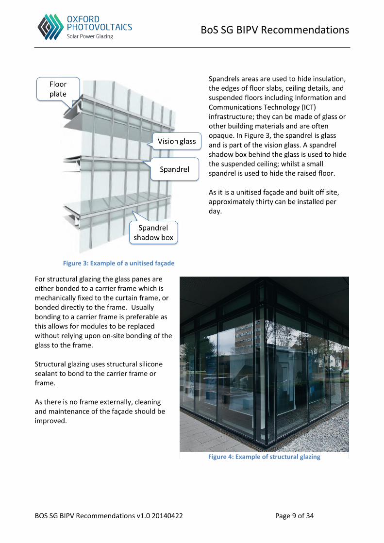
Spandrels areas are used to hide insulation, the edges of floor slabs, ceiling details, and suspended floors including Information and Communications Technology (ICT) infrastructure; they can be made of glass or other building materials and are often opaque. In Figure 3, the spandrel is glass and is part of the vision glass. A spandrel shadow box behind the glass is used to hide the suspended ceiling; whilst a small spandrel is used to hide the raised floor. As it is a unitised façade and built off site, approximately thirty can be installed per day.
For structural glazing the glass panes are either bonded to a carrier frame which is mechanically fixed to the curtain frame, or bonded directly to the frame. Usually bonding to a carrier frame is preferable as this allows for modules to be replaced without relying upon on-site bonding of the glass to the frame. Structural glazing uses structural silicone sealant to bond to the carrier frame or frame. As there is no frame externally, cleaning and maintenance of the façade should be improved.
Figure 3: Example of a unitised façade
Figure 4: Example of structural glazing

BoS SG BIPV Recommendations
BOS SG BIPV Recommendations v1.0 20140422 Page 10 of 34
Challenges for BIPV Applications
The key challenge facing BIPV is the technology straddles the construction and PV industries. The Working Group’s aim was to identify the challenges associated with BIPV glazing products within buildings; and look at possible solutions or best practises to allow adoption of BIPV within buildings. Once we identified the mechanical and electrical challenges, we broke them down into more detail, grouped similar challenges and categorised them into the groups below; working through the challenges and their possible mitigations. The challenges and their mitigations form the rest of this document.
Figure 5: BIPV challenges by category
Examples of the some of the challenges identifies include:
What type of PV electrical topology is suitable?
Where do the cables go within the façade?
How should a BIPV enabled window be replaced in a high-rise building?
Manufacture Installation Design
Maintenance & hand-off
Miscellaneous Commission

BoS SG BIPV Recommendations
BOS SG BIPV Recommendations v1.0 20140422 Page 11 of 34
Glazing Performance
When considering the glazing performance of glass for BIPV applications, the BIPV module manufacture needs to provide g-values, u-values, external reflectance and light transmittance for the BIPV module. The module datasheet should provide at least level of detail as shown in the example in Table 1.
Table 1: Example table from Pilkington Glass
This type of table is very useful as g and u-values are derived figures. They are derived in a layer-by-layer basis, i.e. all the glass in the IGU, not just the BIPV module will impact an IGUs overall transmittance value, and hence g-value. Tools such as IES use generic values to determine u and g-values, but also have the ability to use a layered model approach.
Recommendation 1. BIPV module manufactures provide module datasheets that include glazing specifications to the same level as a glass manufacturer.
Glass manufactures often have software tools to help with IGU design, for example Pilkington Spectrum6 online tool. BIPV module manufactures are encouraged to help inform such on-line tools, or provide their own equivalents.
Recommendation 2. BIPV module manufactures provide design tools for architects and curtain wall designers to assist IGU design.
6 http://spectrum.pilkington.com

BoS SG BIPV Recommendations
BOS SG BIPV Recommendations v1.0 20140422 Page 12 of 34
Shading
Shading is complex in metropolitan areas due to other high-rise buildings in close proximity to one another. Complex shading modelling is often only possible with 3D simulation tools, which calculate shading within a pseudo-real 3D environment; and therefore allow for more realistic energy analysis. Due to the graphical processing nature of 3D modelling, there are limitations with some tools on the number of modules or planes that can be modelled; this is due to limited graphical resource available on the computer. Most buildings where BIPV is applicable could easily exceed this limit. This will in all likelihood mean the building needs to be split into smaller blocks to perform the analysis, or use a suitable on-line tools. The first approach to shading should be a general yes/no cost benefit analysis for BIPV, including which facades of the building BIPV should be applied. Especially within the urban built environment care should be taken to include the current surrounding buildings, and wherever possible looking at future buildings that may impact the PV generation capabilities. This could influence and should inform the PV system topology; i.e. choice of inverters/optimizers and the method of PV array design; and even the design for the BIPV module for that specific building programme.
Recommendation 3. Cost benefit and shading analysis is performed as early as possible within the design process, and should include the current built environment and wherever possible the future built environment.
As building glass can be of any size, determining electrical characteristics for BIPV module can be problematic for the PV designer. Therefore, it is recommended that the BIPV module manufacture provides a simple tool that generates electrical characteristics including at least VOC, ISC, Pmax and MPP, for a given glass size, for example 1500mm x 4000mm.
Recommendation 4. BIPV module manufactures should provide a tool for PV designers to allow quick calculations of PV electrical characteristics for project specific BIPV modules.
Direct light versus diffused light
AECOM has performed real measurements at various locations in the UK, and their results have shown the total diffuse light content versus direct light is higher than might be expected. Over the year the ratio of direct to diffused light can be as high as 50:50, especially the further North you go in the UK. Given the level of diffused light in countries like the UK, it is often assumed that applying PV to the north façade of a building or a north facing roof is not worthwhile. Additionally, for metropolitan areas with a high concentration of buildings, and a higher proportion of diffused or reflected light, then PV is of less value within a façade, especially when there is shading from other buildings.

BoS SG BIPV Recommendations
BOS SG BIPV Recommendations v1.0 20140422 Page 13 of 34
Generally this is because for traditional PV the solar panel requires a higher proportion of direct light, and does not perform as well with diffused or reflected light. With most thin-film PV this is not the case, they work well in diffused and reflected light. Oxford PV’s own modelling of surface irradiation for a number of buildings modelled within London has shown the North façade PV energy generation capabilities can be significant; and should at least be modelled. However, this does not mean that BIPV modules should be installed on the north side of the building, this will be determined by the type of PV being considered and the cost/benefit analysis.
Recommendation 5. The North façade or facades which are shaded should at least be modelled and the result fed into the cost/benefit analysis (see Recommendation 3).
AC/DC Configurations
To give a sense of voltage, current and power requirements for BIPV, Oxford PV gave an example of various glass sizes and their associated electrical parameters; this is shown in Table 2. It should be noted that for spandrels or a shadow box, opaque glass would be used. However, given spandrels are typically smaller than vision glass, the overall current and power will be lower than shown below. The numbers shown are for 60% Visible Light Transmission (VLT).
1.0m x 1.0m
1.5m x 2.75m
1.5m x 3.85
1.5m x 4m
VOC = 107V ISC = 0.8A Pmax = 60W
VOC = 161V ISC = 2.3A Pmax = 248W
VOC = 161V ISC = 3.2A Pmax = 348W
VOC = 161V ISC = 3.4A Pmax = 361W
Table 2: Oxford PV vision glass size characteristics
There are a number of configurations that are possible for BIPV:
AC micro-inverters
DC optimizers with string or central inverter
String inverters (from 3kW up to approximately 30kW)
Central inverters (starting from approximately 500kW)

BoS SG BIPV Recommendations
BOS SG BIPV Recommendations v1.0 20140422 Page 14 of 34
It is highly recommended that as with traditional roof mounted designs, when selecting an inverter or optimizer, the corresponding manufacture’s design tools be used first to select the appropriate product. This can then be imported into the chosen PV analysis tool, and will lead to fewer errors in the PV design. For BIPV the same approach should be adopted.
Recommendation 6. Inverter or optimizer manufacture’s PV tools are used to do initial PV analysis and select the correct inverter or optimizer.
Central inverters
Although the largest from a capacity perspective and therefore from a cost perspective central inverters appear to be the most cost effective, they are deemed unsuitable for BIPV for the following reasons. Firstly, central inverters are generally large and would require a specialised plant room, this space is at a premium in a building. For a typical large office with BIPV, generation might be in the order of 1-2MWp, which would require multiple central inverters. Secondly, central inverters typically only have one or two Maximum Power Point Trackers (MPPT)7. This would severally limit the ability to monitor BIPV modules, and more importantly would reduce overall performance due to so few MPP Trackers, and complex building shading (see Recommendation 3). Finally, using central inverters would mean many strings in parallel and complication in the PV design- particularly around the addition of a large number of string combiner boxes and mitigation needed to handle reverse current module issues.
Recommendation 7. Central inverters should not be used in BIPV applications.
AC micro-inverters and DC optimizers
Metropolitan office clusters will give rise to complex shading; additionally as is the nature of metropolitan areas, the skyline is constantly changing. Both AC micro-inverters and DC optimizers offer good performance in relation to handling shading, where per module MPPT is highly desirable. Additionally they offer the ability to address future changing skylines, whilst still maintaining acceptable performance levels; and both offer an additional benefit in allowing for scheduled maintenance. If it is assumed there is one AC micro-inverter or DC optimizer per BIPV module, i.e. per window, then MPPT and monitoring is also at a very granular level8. In the medium to long-term both these solutions potentially offer a good option for BIPV; with DC optimizers being particularly interesting when considering in-building DC and storage. However, today for commercially available products the voltage output from a BIPV module (Voc) is typically too large for these products to handle; especially when considering the common glazing sizes for building envelopes, as shown in Table 2.
7 MPPT is algorithmic technique usually applied to one or more PV modules to reduce the impact of shading (or partial shading)
upon the PV module or PV array. For example in a PV array of three PV modules connected in series, if one module is shaded its current will be reduced. As it is in series with two other modules, the current for the whole array will be reduced to that of the
shaded module. 8 Some DC optimisers are now being fitted directly into the junction box on the back of traditional PV modules

BoS SG BIPV Recommendations
BOS SG BIPV Recommendations v1.0 20140422 Page 15 of 34
Recommendation 8. In the medium to long-term consider more granular MPPT solutions such as AC micro-inverters or DC optimizers, subject to market availability.
String inverters
In the short to medium-term, the use of string inverters is the most viable solution. Given the nature of an office environment, there are two possible solutions for string inverter locations. Either have all string inverters in their own plant room, or have a distributed design with string inverters located throughout the building. For BIPV installations today, both approaches have been used. It was felt that having them in their own plant room was unnecessary, and would add extra complications to the PV design and overall cabling costs; like central inverters, they would have the same issue, namely plant room space is at a premium. A more elegant solution would be per floor string inverters. This minimizes the overall PV design and cable runs, as the BIPV modules would run to the local string inverter/s. It is likely that two to four string inverters would be required per floor, i.e. one per façade per floor, and would be located within a service riser. This would mean some floor space is lost to allow for an enlarged service riser, however, this compromise was felt to be worthwhile and could be accommodated within the building design. When considering sizing of inverters, it is considered for BIPV applications that the smaller the better, probably in the range of 9 to 12KWp per inverter. Even if this means more than one inverter per floor, the rationale is to allow for greater MPPT and a smaller number of parallel strings.
Recommendation 10. Parallel strings should follow good PV practise (see the Guide to the Installation of Photovoltaic Systems)9 and be no more than three strings in parallel.
9 2nd Edition (2012) published by the Microgeneration Certification Scheme http://www.microgen-
database.org.uk/uploads/34/53/34535a6ed1852e96406ec03c4a46fb2c/New_Guide_to_installlation_of_PV_systems-MCS.pdf
Recommendation 9. Use of per-floor string inverters, mounted in the service risers, which are as small as is practical to allow improved MPPT.

BoS SG BIPV Recommendations
BOS SG BIPV Recommendations v1.0 20140422 Page 16 of 34
Electrical Connection options for BIPV Modules within a Façade
Initially the discussion assumed all electrical connection work would be done from within the building, and all connections would be on the dry side of the building. This would ease the electrical connection and testing stage; and additionally allow for cabling/connectors, which were less expensive- as IP ratings and UV protection would be less stringent for products used internally rather than externally. However, as discussed this was not the only option available. We explored several options for PV cabling, they were as follows:
PV connectors and junction boxes
Vertical stringing within a stick system
Increasing the width of the thermal break
Offsetting IGU glass within the façade
Running cables at the bottom of the façade frame
Running cables in the top or side of the façade frame
Cabling under the cover cap
Cabling within a structural glazing façade
PV connectors and junction boxes
As connector and junction boxes were very much in mind when discussion potential connection options for BIPV modules, it is worth giving a brief overview here. There are a number of commercially available connectors and junction boxes available for PV systems, today they mostly designed with roof or ground-mounted PV systems. This means that they are IP and UV rated for those environments, rather than a building environment. Some products available on the market are specifically designed with BIPV applications in mind.
BoS SG BIPV Recommendations
BOS SG BIPV Recommendations v1.0 20140422 Page 17 of 34
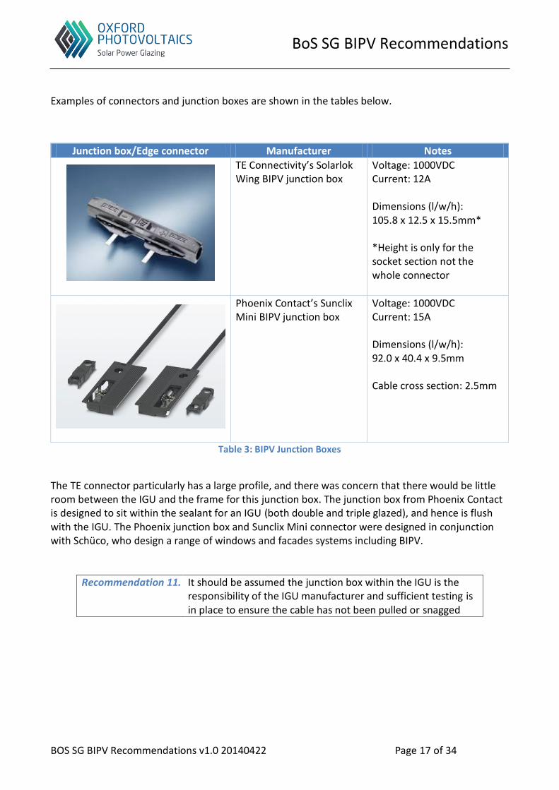
Examples of connectors and junction boxes are shown in the tables below.
Junction box/Edge connector Manufacturer Notes
TE Connectivity’s Solarlok Wing BIPV junction box
Voltage: 1000VDC Current: 12A Dimensions (l/w/h): 105.8 x 12.5 x 15.5mm* *Height is only for the socket section not the whole connector
Phoenix Contact’s Sunclix Mini BIPV junction box
Voltage: 1000VDC Current: 15A Dimensions (l/w/h): 92.0 x 40.4 x 9.5mm Cable cross section: 2.5mm
Table 3: BIPV Junction Boxes
The TE connector particularly has a large profile, and there was concern that there would be little room between the IGU and the frame for this junction box. The junction box from Phoenix Contact is designed to sit within the sealant for an IGU (both double and triple glazed), and hence is flush with the IGU. The Phoenix junction box and Sunclix Mini connector were designed in conjunction with Schüco, who design a range of windows and facades systems including BIPV.
Recommendation 11. It should be assumed the junction box within the IGU is the responsibility of the IGU manufacturer and sufficient testing is in place to ensure the cable has not been pulled or snagged

BoS SG BIPV Recommendations
BOS SG BIPV Recommendations v1.0 20140422 Page 18 of 34
Connector Manufacturer Notes
Multi-Contact MC4 connector
Diameter: 18.8mm Length: Up to 61mm Push fit and lock Crimp tool required Voltage: 1000VDC Current: up to 30A Cable cross section: 2.5. 4 or 6mm
Multi-Contact MC4-EVO 3
Diameter: 19mm Length: Up to 77mm Push fit and lock Crimp tool required Voltage: 1500VDC Current: up to 30A Cable cross section: 2.5. 4 or 6mm
Huber and Suhner
Radox Solar connector
Diameter: 11mm Length: Up to 66mm Push fit and lock Crimp tool required Voltage: 1000VDC Current: up to 38A Cable cross section: 2.5. 4 and 6mm
Phoenix Contact Sunclix mini connector
Diameter: 11mm Length: Max 55mm Push fit and lock No tools required Voltage: 1000VDC Current: 15A Cable cross section: 2.5mm
Table 4: PV connectors
The MC4 connector is widely used within the PV industry, and was designed by Multi-Contact. There are other ‘copy’ MC4 connectors available from other suppliers, has become a defacto standard. Again space within the frame will be a challenge for the MC4 style connector in BIPV applications. Multi-contact updated us on their new MC4-EVO 3 connector. Which has flat design compared to the standard MC4, and a lower profile. The DC rating is also improved and can handle 1500V.

BoS SG BIPV Recommendations
BOS SG BIPV Recommendations v1.0 20140422 Page 19 of 34
The other type of connector often used due to its small profile is Radox Solar connector by Huber and Suhner. This is a pencil thin in-line connector and has been used on some of the UK BIPV installations. Another type of pencil connector is Phoenix Contact’s Sunclix Mini range, as with their junction box they were also designed in conjunction with Schüco. For the Radox and Sunclix Mini connectors, and possibly the MC4-EVO 3, their compact design would help with space, and might be accommodated within the frame. Therefore if suitable solutions are available that allow a connector to be mounted or used in the top or side of the frame, then these solutions should not be excluded.
Recommendation 12. Cable running in the top or side of the frame should be permitted if a suitable low-profile PV connectors are used
There was also a very brief but important discussion on mixing of connectors from different manufactures. This is allowed today, for example you can use an MC4 from Multi-Contact with another manufactures MC4. This is allowed along with supporting documentation. Going forward, it is very likely we will follow the IEC approach and disallow mixing of connector types, as it is known there is a chance of an increased failure rate for connectors.
Recommendation 13. Only Connectors from one manufacturer are used per project
There was no specific recommendation on the connector to be used; however it must be of the appropriate IP, UV and temperature ratings suitable for the intended environment. For further details see the Guide to the Installation of Photovoltaic Systems, section 2.
Recommendation 14. Connectors and cables use, ratings and performance should follow MCS’ Guide to the Installation of Photovoltaic Systems
Vertical stringing within a stick system
For a stick system there was a suggestion of connecting the BIPV system in the vertical direction within the building, rather than connection on a per-floor basis. However, given that in the first instance string inverters would need to be used, it was felt that connection on a per-floor basis was preferable, and would simplify the electrical design.
Recommendation 15. Horizontal PV stringing is preferred in a stick based façade system.

BoS SG BIPV Recommendations
BOS SG BIPV Recommendations v1.0 20140422 Page 20 of 34
Increasing the width of the thermal break
We discussed increasing the width of the thermal break to accommodate the cable, this area is identified in Figure 6; Figure 7 shows the same frame in profile. However, this was felt not to be an option as from an architectural perspective this would increase the size of the site lines on the façade. Additionally internal space within the frame is at minimum to keep u-values as low as possible. Increasing the size would create convection currents, hence increasing u-values, and thus reducing the level of insulation provided by the facade.
Figure 6: 3D example of Hueck's Trigon 50/60
Recommendation 16. The thermal break width is not increased to accommodate PV cabling within the façade.

BoS SG BIPV Recommendations
BOS SG BIPV Recommendations v1.0 20140422 Page 21 of 34
Figure 7: Cross-section example of Hueck’s Trigon 50/60

BoS SG BIPV Recommendations
BOS SG BIPV Recommendations v1.0 20140422 Page 22 of 34
Offsetting IGU glass within the façade
We discussed offsetting the glass within the frame so it does not touch the thermal break, and cables can fit within the gap. Reducing one or more glass panes within the frame, may lead to differential deflection which could cause glass to ‘pop’ out of the frame.
Recommendation 17. That no IGU panes are offset from the edge of the frame to accommodate PV cabling
Running cables at the bottom of the façade frame
Figure 8: Example of IGU on setting blocks
Within a façade the IGU sits upon setting blocks. The setting blocks vary in size depending upon the size of the IGU. The purpose of the setting blocks is three-fold, firstly to transfer the load of the glazing to the framing system at defined points. Secondly, to stop the edges of the IGU from coming into contact with the metal edges of the framing system; and thirdly to stop the IGU sealant from sitting in water. It should be noted that other blocks are used around the frame to help position the IGU within the facade. We discussed the possibility of running the PV cable/connectors within the channel or recess created by the setting blocks. However, given this channel/recess is used for drainage purposes within the façade, would most likely mean the presence of water on a regular basis. It was felt this was not a sensible place for the PV connectors or cabling. Additionally, current PV cables assuming a 4mm or 6mm core plus cable insulation, this could mean practically that there may be no room for the PV cable/connector.
Recommendation 18. That PV cabling is not routed within the setting block channel or recess at the bottom of the IGU

BoS SG BIPV Recommendations
BOS SG BIPV Recommendations v1.0 20140422 Page 23 of 34
Running cables in the top or side of the façade frame
We also discussed cabling on the side or top, both of which could be options. The challenge with this option will be:
Choosing the right connector and junction box solution that will fit within the available space
IGU maintenance/replacement where access is needed to the cable and connectors As Table 3 and Table 4 show there are products available that are suitable, particularly the MC4-EVO, Radox and Sunclix Mini. Therefore if suitable solutions are available that allow a connector to be mounted or used in the top or side of the frame, then these solutions should not be excluded, subject to the addressing the challenges above.
Recommendation 19. Cable running in the top or side of the frame should be permitted if a suitable low-profile solutions is available
Running cables within the façade back box
We did not discuss this at the meeting, however it is mentioned here as it might be a possibility and is used for some actuator cabling today. The challenges will be:
Connectors would not be accessible externally when needing to replace the IGU
An access plate per window would be required, this may or may not be visible to the building users
Cabling under the face cap
This is only applicable for either a stick system or non-structural glazing unitised façade. We considered running some of the cable on the outside of the building within the façade face or cover caps. The caps are only decorative and used to hide bolts or screws, see Figure 6 and Figure 7 as an example. The cap is seen as a sensible option as there is generally more room here, and if an IGU is replaced then this cover cap is easily accessible externally. We discussed further this possibility; Figure 9 is shown as an example to help with text:
A connector socket and plug (A and B) are on the outside of the building. This should be assumed to be a wet environment, i.e. an external environment10.
Looking at an MC4 style connector, it was thought there should be enough room under the cover cap to place these connectors, or other smaller in-line connectors.
A notch would be needed in one side of the thermal break to accommodate the PV cable.
10 Depending upon the façade this area might need cabling that is IP and UV rated, see Recommendation 14

BoS SG BIPV Recommendations
BOS SG BIPV Recommendations v1.0 20140422 Page 24 of 34
Sufficient cable slack should be allowed between connectors B and C. To allow an IGU to be uncoupled from the frame.
A cable would come from the IGU and be terminated in connector A, through the pressure plate.
o This requires a grommet and should be suitably sealed
Connector B would connect to this and the cable would run through the frame and be terminated on the dry side (inside) by connector C. The rest of the system connection can therefore take place within the building.
o This assumes robust testing of the BIPV façade, including connectors A, B and C, including any associated cable.
It should be noted that Sundog have many examples of connectors burning out, the proposal here will introduce extra connectors than might normally be seen in a PV design.
Figure 9: Example of Hueck Trigon 50/60 unitised facade
An alternative solution would be for the thermal break to be milled out between pressure plate fixing screws, and the PV connection could be made in this zone, i.e. under the pressure plate. This depends on system manufacturers allowance for notching out of the thermal break. However, the advantage is no hole is needed in the pressure plate. Today some unitised facades with built in electronics, such as actuators, have a pre-fabricated stowage place for the cable and connector. This reduces the chance of snagging cables whilst in transit or prior to installation.

BoS SG BIPV Recommendations
BOS SG BIPV Recommendations v1.0 20140422 Page 25 of 34
Recommendation 20. An anti-snagging option is considered on the façade to protect the solar cables prior to installation
Recommendation 21. For stick and unitised facades with cover or face caps the preferred connection for BIPV modules is utilising the space under the cover cap
Cabling within a structural glazing façade
Figure 10 shows and example of structural glazing. The glass panes are either bonded to a carrier frame which is mechanically fixed to the curtain frame, or bonded directly to the frame. Structural glazing uses structural silicone sealant to bond to the carrier frame or frame.
Unlike other unitised façades this type of façade does not have a face or cover cap. Therefore, connectors cannot be hidden under the cap. For double glazing systems, this will probably mean all connections are inside the building and not accessible externally. For triple glazing it might be possible use another recessed spacer and run the connectors in this area, typically between panes 4 and 5, with pane 1 being the outside. Another possibility for structural glazing might be notching out the thermal break as with the ‘Cabling under the face cap’ option. However, for these possible solutions the façade manufactures framing system will have a large influence over these possibilities. Sundog have experience of installing structural glazing, and they have used junction boxes hidden behind structural members.
Figure 10: Hueck 50/60 structural glazing
BoS SG BIPV Recommendations
BOS SG BIPV Recommendations v1.0 20140422 Page 26 of 34
For structural glass facades replacing the IGU means cutting the silicon sealant away from the frame. This is done externally, and usually with specialised glazing tools. It is important that the PV cable is protected from any damage. Façade designers and fabricators may need to consider a protective casing to prevent this, this is highlighted in the figure above by the red line.
Internal cabling
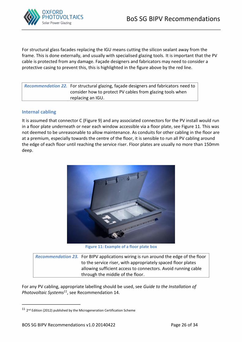
It is assumed that connector C (Figure 9) and any associated connectors for the PV install would run in a floor plate underneath or near each window accessible via a floor plate, see Figure 11. This was not deemed to be unreasonable to allow maintenance. As conduits for other cabling in the floor are at a premium, especially towards the centre of the floor, it is sensible to run all PV cabling around the edge of each floor until reaching the service riser. Floor plates are usually no more than 150mm deep.
Figure 11: Example of a floor plate box
Recommendation 23. For BIPV applications wiring is run around the edge of the floor to the service riser, with appropriately spaced floor plates allowing sufficient access to connectors. Avoid running cable through the middle of the floor.
For any PV cabling, appropriate labelling should be used, see Guide to the Installation of Photovoltaic Systems11, see Recommendation 14.
11 2nd Edition (2012) published by the Microgeneration Certification Scheme
Recommendation 22. For structural glazing, façade designers and fabricators need to consider how to protect PV cables from glazing tools when replacing an IGU.

BoS SG BIPV Recommendations
BOS SG BIPV Recommendations v1.0 20140422 Page 27 of 34
Connecting a BIPV module
The example of The Shard whilst being constructed is shown below in Figure 12 below. When constructing a high-rise building, the core is built first floor by floor. The rest of the floor is built around the core, and the building façade added to seal the floor. Typically the electrical install will be several floors behind the core and floor build. Once the façade is added the floor is usually considered dry. There may still be some water on the lower floors as the water can come into the open end of the façade closest to the top of the building. At this point trades such as electrician can work on the floor.
It cannot be assumed that the façade installation and the rest of PV electrical are carried out simultaneously. Therefore, any installation of the BIPV façade should not leave any exposed live cables without adequate termination or protection.
Recommendation 24. All cables are appropriately terminated prior to site installation with touch safe connectors (see Table 4: PV connectors).
For unitised facades it is recommended that in addition to the normal fabrication, that the system comes pre-fabricated including the PV cable and connectors. The external cable should be terminated in an appropriate PV connector. This ensures that there is no live exposed PV conductor during the façade installation.
Figure 12: Typical construction methods for high-rise buildings

BoS SG BIPV Recommendations
BOS SG BIPV Recommendations v1.0 20140422 Page 28 of 34
Recommendation 25. To speed up façade installation it is recommended that for each unitised façades that all cabling is done as part of the façade fabrication process; and likewise for stick systems as much is done as possible prior to installation.
We discussed whether BIPV IGUs would need PV covers, to prevent modules generating DC whilst being installed. However, the PV industry abandoned PV covers, as they created extra site litter and got in the way of installation. Touch safe connectors removed the need for covers.
Recommendation 26. BIPV module covers are not required for the façade prior to installation, as touch-safe connectors should be used.
Whether connecting a unitised or stick BIPV system, the hole used to pass the cable through, should be sufficiently large to allow the connector to be passed through the façade, i.e replacing the cable between connectors B and C. Drilling a hole in the façade is not uncommon and done today for attaching a brise soleil to the building.
Summary of BIPV cabling options
Option Comments
Increase thermal break width size
Not seen as an option, as this would increase the site lines and potentially increase the u-value of the façade.
Run cables/connectors within back box
This might be an option. However, cable accessibility from outside needs to be considered when replacing an IGU.
Offsetting IGU glass within the façade
Not seen as an option as there is a potential with façade movement to have the glass pop out of the frame.
Cable/connectors running near setting blocks
This is not seen as an option as this area is a water channel
Cable/connector on the top or side of the IGU
Might be an option if a connector with a suitably low profile is available. However, cable accessibility from outside needs to be considered when replacing an IGU.
Run cables/connectors within façade cover cap
A preferred option for stick or unitised facades (excluding structural silicone glazing). The cover cap is decorative only and used to hide façade bolts. There is sufficient room to have connectors under the cap, and they can be disconnected from the outside. However, any cabling must not impact the drainage capacity for the face cap.
Structural glazing As structural glazing has no cover cap, connectors are likely to be on the inside of the building. Although it may be possible to accommodate the connectors within the framing system, by notching out the thermal break or using a recessed spacer. However, this is subject to the façade framing system used.
Table 5: BIPV cable and connector run options

BoS SG BIPV Recommendations
BOS SG BIPV Recommendations v1.0 20140422 Page 29 of 34
IGU Replacement and Maintenance
Over the life-time of the façade, some glass panels will need to be replaced; this is done by disconnecting the glass Insulated Glass Unit (IGU) from the façade frame and replacing it. Replacing glass can be done in one of two ways. Firstly, from within the building by use of a glazing robot or similar. An example is shown in Figure 13.
Figure 13: Example of a glazing robot
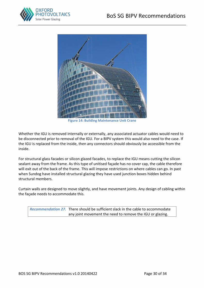
Secondly, IGUs can be replaced from outside the building using a Building Maintenance Unit (BMU) or spider crane. This is a more common approach, as there is usually not enough access space for a glazing robot once the building is occupied. Figure 14 shows and example of this type of crane.
BoS SG BIPV Recommendations
BOS SG BIPV Recommendations v1.0 20140422 Page 30 of 34
Figure 14: Building Maintenance Unit Crane
Whether the IGU is removed internally or externally, any associated actuator cables would need to be disconnected prior to removal of the IGU. For a BIPV system this would also need to the case. If the IGU is replaced from the inside, then any connectors should obviously be accessible from the inside. For structural glass facades or silicon glazed facades, to replace the IGU means cutting the silicon sealant away from the frame. As this type of unitised façade has no cover cap, the cable therefore will exit out of the back of the frame. This will impose restrictions on where cables can go. In past when Sundog have installed structural glazing they have used junction boxes hidden behind structural members. Curtain walls are designed to move slightly, and have movement joints. Any design of cabling within the façade needs to accommodate this.
Recommendation 27. There should be sufficient slack in the cable to accommodate any joint movement the need to remove the IGU or glazing.

BoS SG BIPV Recommendations
BOS SG BIPV Recommendations v1.0 20140422 Page 31 of 34
Glass Safety
The nature of BIPV modules, especially with lighter tints on vision glass and darker tints for spandrels coupled with building shading, will mean a higher potential for problems. However with good glass processing techniques, many of these issues can be mitigated. There is a great deal already written about glass safety and appropriate use of glazing. BIPV glazing modules do not particularly change the basic principles and therefore following best practise should be sufficient. Below are some of the relevant UK documents (this list is not exhaustive and shown as an example only):
Approved Document K (part of The Building Regulations 2013) ‘Protection from falling, collision and impact’
BS 6206:1981 ‘Specification for: Impact performance requirements for flat safety glass and safety plastics for use in buildings’
BS EN 12600:2000 ‘Glass in building – Pendulum test – Impact test method and classification for flat glass’
BRE Digest 453 ‘Insulating Glazing Units’
BS EN 1279-4:2002 ‘Glass in building – Insulating glass units – Part 4: Methods of test for the physical attributes of edge seals’
Additionally The Centre for Window and Cladding Technology (CWCT12 ) produces a series of Technical Notes for the building industry. They can be found at their website below.
Recommendation 28. BIPV modules from a glazing perspective should follow good industry best practise and the local building regulations
Nickel Sulphide inclusions
This is a potential issue with thermally toughened glass. However, there is a move away from using monolithic toughened glass in the outer pane due to the risk of it failing and falling. If the BIPV module is a laminated product this should not be an issue, therefore normal guidance applies.
Thermal shock
Efficiencies for BIPV modules is directly related to their level of transparency. The more transparent, and the lower the efficiency, and the higher the Visible Light Transmission (VLT); the more opaque then the higher the efficiency and conversely the lower the VLT. BIPV vision glass, therefore will be semi-transparent, with the VLT being in an acceptable range for vision glass. This will mean the BIPV module will have either some colour, tint or both to the glass. The colour/tint of the BIPV will affect the solar absorption and therefore the temperature the glass reaches. An assessment is usually carried out by the glass supplier or processor. Please see Thermal Fracture of Glass Technical Note TN65 for further details.
12 http://www.cwct.co.uk/

BoS SG BIPV Recommendations
BOS SG BIPV Recommendations v1.0 20140422 Page 32 of 34
Blast proof
Where and what is required when considering blast proof glass is subject to national regulations. Below is an extract from UK’s CNPI (Centre for the Protection of the National Infrastructure) on glazing and blast proof. ‘As up to 95% of all injuries from a bomb are caused by flying or falling glass, the quality of glazing protection is important. Glazing measures are currently available which can either mitigate the effects from a blast threat by reducing the number of fragments entering the room, or protect the occupants from a specified blast threat and the fragments by remaining in the frame. It is important to understand the level of risk in order to determine the appropriate glazing enhancement. Where blast enhancement is required, laminated glass in normal window frames are generally recommended as a minimum.’13 Additionally CWCT has a technical note TN7 on the subject, called Threat Resistant Fenestration (currently being revised).
Fire Safety Perceptions
We started the discussion by asking Martin Cotterell about the experiences he has seen as representing various solar bodies and the National Solar Centre (NSC). Kevin mentioned the presentation he found from Bill Brooks, of Brooks Engineering, which shows examples of PV panels which had been removed from the roof by the Fire Brigade14. The big challenge is the perceived risk, rather than actual risk. Most houses in the UK have piped gas and are connected to the mains, yet these are deemed acceptable risks, which can be dealt with. There is a need to engage with the various Fire Brigades within the country, and maybe even Building Control Boards. Unfortunately, each Fire Brigade has its own operating procedures, so there is no central place to engage with the UK Fire Brigades as a whole. AECOM mentioned a few years ago there was a similar issue with biomass emissions and EU Nitrogen Oxide (NOx) levels. It has settled down now, however it did negatively impact biomass rollout within cities. DEFRA brought in a new assessment criteria to mitigate the concern, and this is now used for any biomass proposal15. The National Solar Center (NSC) is working with the IET and Fire Brigades to help educate the Fire Brigades. The new IET code of practise may supplant the MCS equivalent eventually. There is a
13 http://www.cpni.gov.uk/advice/Physical-security/ebp/ 14 www.nfpa.org/~/media/files/proceedings/photovoltaicbrooks.pdf 15 www.iapsc.org.uk/document/0609_E_Dearnley.pdf

BoS SG BIPV Recommendations
BOS SG BIPV Recommendations v1.0 20140422 Page 33 of 34
press release coming shortly to announce the start of the new IET PV code of practise, which would include hazard inventory. BRE has produced some useful background material related to fire safety16. They concluded ‘At the present time there is no reason to believe that the fire risks associated with PVs are any greater than those associated with any other electrical equipment. But, as with all electrical equipment, it is important that these systems are correctly designed, consist of properly tested components, are competently installed and are regularly maintained.’
Construction Design and Management Regulations
The conversation moved onto how companies like Oxford PV could help provide more information, guidance or user manuals on using BIPV technologies.
Mark mentioned Construction Design and Management (CDM) regulations; the Health and Safety Executive (HSE) publish the Approved Code of Practice and produce guidance17. Its aim is to improve health and safety, and focuses on effective planning and management/mitigation of risk. CDM is a legally binding and carries criminal penalties if the regulations are broken. It covers areas such as:
Construction
Maintenance and use (operations and maintenance)
Demolition Documentation from BIPV manufactures will form part of the O&M for the building. Besides the obvious things like datasheets for the BIPV modules, it goes beyond this and would include things like:
Risk assessment of BIPV manufactures technology on users of the building, including those adjacent services that could be impacted by the technology. For example, does the window cleaner need to take any special precautions when cleaning the BIPV windows? Or do the windows need more regularly cleaning because they now contain PV elements?
It is a system level assessment, not just looking the BIPV modules themselves, but would include questions like ‘Are the inverters easily assessable for O&M purposes? Is any special equipment required to give access, for example an access platform?’
Much of this information would be contained in the Maintenance Access Strategy document, and is usually instigated by the architect.
The information that is gathered for CDM forms part of the handover documentation provided to the building owner. Historically, this has been all paper based; however with Building Integration Management (BIM), this is now moving towards electronic forms. New initiatives such as COBie, (Construction Operations Building Information Exchange), are helping speed up this transition; and provide a systemised approach and output from BIM.
16 http://www.bre.co.uk/page.jsp?id=3211 17 http://www.hse.gov.uk/construction/cdm.htm

BoS SG BIPV Recommendations
BOS SG BIPV Recommendations v1.0 20140422 Page 34 of 34
Figure 15: What is COBie?18
As many of the new office buildings are so complex there is often an Information package that forms part of the tender documents, other examples of packages include the Façade package or Mechanical and Electrical package. The Information package would provide the maintenance and cleaning schedule for the building. For companies producing BIPV modules, areas like hazard inventory mentioned by the IET PV Codes of Practise and CDM, will play a very important role in the level of detailed documentation to be provided as part of the construction value chain.
18 From the BIM Task Group http://www.bimtaskgroup.org/cobie-uk-2012/