BMS Gateway BMS-GW (ProtoAir FPA-W44) Start-up Guide For ...
52
Document Revision: 1.A Auto Discovery Template Revision: 3 BMS Gateway BMS-GW (ProtoAir FPA-W44) Start-up Guide For Interfacing the SimplySNAP Site Controller (SS420/450) To Building Automation Systems: BACnet MS/TP, BACnet/IP, Modbus RTU and Modbus TCP/IP APPLICABILITY & EFFECTIVITY Explains BSM-GW/ProtoAir hardware and how to install it. The instructions are effective for the above as of February 2019.
Transcript of BMS Gateway BMS-GW (ProtoAir FPA-W44) Start-up Guide For ...

Document Revision: 1.A Auto Discovery
Template Revision: 3
BMS Gateway BMS-GW (ProtoAir FPA-W44) Start-up Guide
For Interfacing the SimplySNAP Site Controller (SS420/450)
To Building Automation Systems: BACnet MS/TP, BACnet/IP, Modbus RTU and Modbus TCP/IP
APPLICABILITY & EFFECTIVITY
Explains BSM-GW/ProtoAir hardware and how to install it.
The instructions are effective for the above as of February 2019.

SimplySNAP BMS Gateway/ProtoAir Start-up Guide
Contact Information
Technical Support
Thank you for purchasing the BMS Gateway/ProtoAir from Synapse Wireless. Please call Synapse Wireless for technical support of the BMS Gateway/ProtoAir product. Sierra Monitor Corporation does not provide direct support. If Synapse Wireless needs to escalate the concern, they will contact Sierra Monitor Corporation for assistance. Support Contact Information:
Synapse Wireless 6723 Odyssey Drive Huntsville, Alabama 35806 Customer Service: 877-982-7888
Website: www.synapsewireless.com
Additionally, a ticket can be opened at www.synapse-wireless.com/resources/contact-support/

SimplySNAP BMS Gateway/ProtoAir Start-up Guide
Quick Start Guide
Quick Start Guide
1. Record the information about the unit. (Section 3.1)
2. Configure COM settings for the device to connect to the BMS-GW/ProtoAir. (Section 3.2)
3. Connect the BMS-GW/ProtoAir 3 pin RS-485 R2 port to the field protocol cabling. (Section 4.1)
4. Connect power to the BMS-GW/ProtoAir’s 3 pin connector. (Section 4.4)
5. Connect a PC to the BMS-GW/ProtoAir via Ethernet cable or by the BMS-GW/ProtoAir’s Wi-Fi Access
Point. (Section 5)
6. Set the field protocol settings via the Web Configurator. (Section 7.1)
7. Use the Discovery function to configure the BMS-GW/ProtoAir and to find any connected devices.
(Section 7.2)

SimplySNAP BMS Gateway/ProtoAir Start-up Guide
Table of Contents
TABLE OF CONTENTS
1 Certification .......................................................................................................................................... 7 1.1 BTL Mark – BACnet® Testing Laboratory ....................................................................................... 7
2 Introduction .......................................................................................................................................... 8 2.1 ProtoAir Gateway ............................................................................................................................ 8
3 ProtoAir Setup ...................................................................................................................................... 9 3.1 Record Identification Data .............................................................................................................. 9 3.2 Configuring Device Communications ............................................................................................. 9 3.3 Attaching the Antenna .................................................................................................................... 9
4 Interface the ProtoAir to Devices ..................................................................................................... 10 4.1 Wiring Field Port to RS-485 Serial Network ................................................................................. 10 4.2 Bias Resistors ............................................................................................................................... 11 4.3 Termination Resistor..................................................................................................................... 12 4.4 Power-Up ProtoAir ........................................................................................................................ 13
5 Connect the PC to the ProtoAir ........................................................................................................ 14 5.1 Connecting to the ProtoAir via Ethernet ....................................................................................... 14
5.1.1 Enable Access Through the Local Browser .......................................................................... 14 5.1.1.1 Changing the Subnet of the Connected PC ................................................................... 14 5.1.1.2 Changing the IP Address of the ProtoAir with FieldServer Toolbox .............................. 15
5.2 Connecting to the ProtoAir Over Wi-Fi Access Point ................................................................... 16
6 Update Network Settings .................................................................................................................. 17 6.1.1 Common Settings .................................................................................................................. 18 6.1.2 Update Wired Network Settings ............................................................................................ 19 6.1.3 Update Wi-Fi Client Settings ................................................................................................. 20
7 Configure the ProtoAir ...................................................................................................................... 21 7.1 Select BMS Protocol and Configure Settings ............................................................................... 21
7.1.1 BACnet Settings – Additional Information ............................................................................. 22 7.1.1.1 Setting the MAC Address for the BACnet MS/TP Network ............................................ 22 7.1.1.2 Set the ProtoAir BACnet Device Instance ...................................................................... 23
7.1.2 Modbus Settings – Additional Information ............................................................................. 24 7.1.2.1 Setting the Modbus Slave ID.......................................................................................... 25
7.2 Discover Devices Connected to the ProtoAir ............................................................................... 26 7.3 Configure Devices and Data Points .............................................................................................. 27
7.3.1 General Configuration Instructions ........................................................................................ 27 7.3.2 Modbus Map Window ............................................................................................................ 29
7.4 Clearing Configuration .................................................................................................................. 30
Appendix A Troubleshooting ................................................................................................................... 31 Appendix A.1 Lost or Incorrect IP Address ............................................................................................. 31 Appendix A.2 Viewing Diagnostic Information ........................................................................................ 32 Appendix A.3 Checking Wiring and Settings ........................................................................................... 33 Appendix A.4 LED Diagnostics for Communications Between ProtoAir and Devices ............................ 34 Appendix A.5 Taking a FieldServer Diagnostic Capture ......................................................................... 35
Appendix A.5.1 Using the FieldServer Toolbox ................................................................................... 35 Appendix A.5.2 Using FS-GUI ............................................................................................................. 38
Appendix A.6 Wi-Fi Signal Strength ........................................................................................................ 39 Appendix A.7 Factory Reset Instructions ................................................................................................ 39 Appendix A.8 Kaspersky Endpoint Security 10 ....................................................................................... 40

SimplySNAP BMS Gateway/ProtoAir Start-up Guide
Table of Contents
Appendix B Additional Information ......................................................................................................... 41 Appendix B.1 SSL/TLS for Secure Connection ....................................................................................... 41
Appendix B.1.1 Configuring FieldServer as a SSL/TLS Server .......................................................... 41 Appendix B.1.1.1 Simple Secure Server Configuration ................................................................... 41 Appendix B.1.1.2 Limiting Client Access.......................................................................................... 42 Appendix B.1.1.3 Upload the Authority File to the FieldServer ........................................................ 42 Appendix B.1.1.4 Certificate Validation Options .............................................................................. 43 Appendix B.1.1.5 Set up Server Certificate ..................................................................................... 43
Appendix B.1.2 Configuring FieldServer as SSL/TLS Client ............................................................... 44 Appendix B.1.2.1 Simple Secure Client Configuration ..................................................................... 44 Appendix B.1.2.2 Limit Server Access ............................................................................................. 44 Appendix B.1.2.3 Certificate Validation Options .............................................................................. 44 Appendix B.1.2.4 Set up Client Certificate ....................................................................................... 44
Appendix B.2 Updating Firmware ............................................................................................................ 45 Appendix B.3 BACnet: Setting Network_Number for More Than One ProtoAir on the Subnet .............. 45 Appendix B.4 Securing ProtoAir with Passwords .................................................................................... 46 Appendix B.5 Wi-Fi Access Point Network Settings ............................................................................... 47 Appendix B.6 Mounting ........................................................................................................................... 48 Appendix B.7 Physical Dimension Drawing ............................................................................................ 49 Appendix B.8 Structure of the Device Tree ............................................................................................. 50
Appendix C Reference .............................................................................................................................. 51 Appendix C.1 Specifications .................................................................................................................... 51
Appendix C.1.1 Compliance with UL Regulations ............................................................................... 51
Appendix D Limited 2 Year Warranty ...................................................................................................... 52

SimplySNAP BMS Gateway/ProtoAir Start-up Guide
Page 6 of 52
LIST OF FIGURES
Figure 1: ProtoAir Part Numbers ................................................................................................................... 9 Figure 2: Connection from ProtoAir to RS-485 Field Network .................................................................... 10 Figure 3: Bias Resistor DIP Switches ......................................................................................................... 11 Figure 4: Termination Resistor DIP Switch ................................................................................................. 12 Figure 5: Required Current Draw for the ProtoAir....................................................................................... 13 Figure 6: Power Connections ...................................................................................................................... 13 Figure 7: Ethernet Port Location ................................................................................................................. 14 Figure 8: Web Configurator Landing Page – Showing Network Settings Tab ............................................ 17 Figure 9: Common Network Settings .......................................................................................................... 18 Figure 10: Ethernet Port Network Settings ................................................................................................. 19 Figure 11: Wi-Fi Client Network Settings .................................................................................................... 20 Figure 12: Select BMS Protocol .................................................................................................................. 21 Figure 13: BACnet MS/TP Settings Window............................................................................................... 22 Figure 14: BACnet/IP Settings Window ...................................................................................................... 23 Figure 15: Modbus RTU Settings Window .................................................................................................. 24 Figure 16: Modbus TCP/IP Settings Window – Using Slave ID .................................................................. 25 Figure 17: Modbus TCP/IP Settings Window – Using Slave ID Offset ....................................................... 25 Figure 18: Discovery Window ..................................................................................................................... 26 Figure 19: Discovering Devices .................................................................................................................. 26 Figure 20: The Device Tree ........................................................................................................................ 27 Figure 21: View & Change Parameters on a Point ..................................................................................... 27 Figure 22: View & Edit Node Parameters ................................................................................................... 28 Figure 23: Saving Configurations ................................................................................................................ 28 Figure 24: Saved Configurations ................................................................................................................ 28 Figure 25: Modbus Map Window ................................................................................................................ 29 Figure 26: Saved Configurations ................................................................................................................ 29 Figure 27: Clear Configuration Window ...................................................................................................... 30 Figure 28: Ethernet Port Location ............................................................................................................... 31 Figure 29: Error Messages Screen ............................................................................................................. 32 Figure 30: Nodes Information Screen ......................................................................................................... 32 Figure 31: Diagnostic LEDs ........................................................................................................................ 34 Figure 32: Ethernet Port Location ............................................................................................................... 35 Figure 33: Wi-Fi Signal Strength Listing ..................................................................................................... 39 Figure 34: Kaspersky ES10 Settings .......................................................................................................... 40 Figure 35: Web Anti-Virus Trusted URLs .................................................................................................... 40 Figure 36: Web Configurator – Network Number Field ............................................................................... 45 Figure 37: FS-GUI Passwords Page ........................................................................................................... 46 Figure 38: Password Recovery Page ......................................................................................................... 46 Figure 39: Wi-Fi AP Network Settings ........................................................................................................ 47 Figure 40: DIN Rail ...................................................................................................................................... 48 Figure 41: ProtoAir FPA-W44 Dimensions ................................................................................................. 49 Figure 42: Specifications ............................................................................................................................. 51

SimplySNAP BMS Gateway/ProtoAir Start-up Guide
Page 7 of 52
1 CERTIFICATION
1.1 BTL Mark – BACnet®1 Testing Laboratory
1 BACnet is a registered trademark of ASHRAE
The BTL Mark on ProtoAir is a symbol that indicates that a product has
passed a series of rigorous tests conducted by an independent laboratory
which verifies that the product correctly implements the BACnet features
claimed in the listing. The mark is a symbol of a high-quality BACnet product.
Go to www.BACnetInternational.net for more information about the BACnet
Testing Laboratory. Click here for the BACnet PIC Statement.

SimplySNAP BMS Gateway/ProtoAir Start-up Guide
Page 8 of 52
2 INTRODUCTION
2.1 ProtoAir Gateway
NOTE: The BMS Gateway (BMS-GW) is a co-branded hardware and software solution
manufactured by Sierra Monitor Corporation (SMC). The Synaspe Wireless p/n for this
product is BMS-GW. However, within this document, the BMS-GW will be referred to as the
ProtoAir, which is the product name provided by SMC.
The ProtoAir wireless gateway is an external, high performance building automation multi-protocol
gateway that is preconfigured to auto-discover the SimplySNAP site controller SS420/450 (hereafter simply
called “device”) connected to the ProtoAir and automatically configures them for BACnet/IP, BACnet
MS/TP, Modbus TCP/IP and Modbus RTU.
It is not necessary to download any configuration files to support the required applications. The ProtoAir is
pre-loaded with tested profiles/configurations for the supported devices.
FPA-W44 Connectivity Diagram:
The ProtoAir can connect with Sierra Monitor’s SMC Cloud. The SMC Cloud allows technicians, the OEM's
support team and Sierra Monitor's support team to remotely connect to the ProtoAir. The SMC Cloud
provides the following capabilities for any registered devices in the field:
• Remotely monitor and control devices.
• Collect device data and view it on the SMC Cloud Dashboard and the SMC Smart Phone App.
• Create user defined device notifications (alarm, trouble and warning) via SMS and/or Email.
• Generate diagnostic captures (as needed for troubleshooting) without going to the site.
For more information about the SMC Cloud, refer to the SMC Cloud Start-up Guide.

SimplySNAP BMS Gateway/ProtoAir Start-up Guide
Page 9 of 52
3 PROTOAIR SETUP
3.1 Record Identif ication Data
Each ProtoAir has a unique part number located on the side or the back of the unit. This number should be
recorded, as it may be required for technical support. The numbers are as follows:
Model Part Number
ProtoAir FPA-W44-1620
Figure 1: ProtoAir Part Numbers
• FPA-W44 units have the following 3 ports: RS-485 + Ethernet + RS-485
3.2 Configuring Device Communications
• The device needs to be on the same IP subnet as the ProtoAir and the configuration PC.
• Record the following device information:
o IP Address
o IP Port
o Username
o Password
NOTE: This information is required for Section 7.
3.3 Attaching the Antenna
Wi-Fi Antenna:
Screw in the Wi-Fi antenna to the front of the unit as shown in Figure 41.
NOTE: Using an external antenna is also an option. An external antenna can be plugged into the
SMA connector. The best antenna for the job depends on the range, topography and
obstacles between the two radios.

SimplySNAP BMS Gateway/ProtoAir Start-up Guide
Page 10 of 52
4 INTERFACE THE PROTOAIR TO DEVICES
4.1 Wiring Field Port to RS-485 Serial Network
• Connect the RS-485 network wires to the 3-pin RS-485 connector on the R2 port. (Figure 2)
o Use standard grounding principles for RS-485 GND
• See Section 6 for information on connecting to an Ethernet network.
BMS Wiring
ProtoAir Pin #
Pin Assignment
RS-485 + Pin 1 RS-485 +
RS-485 - Pin 2 RS-485 -
- Pin 3 RS-485 GND
Figure 2: Connection from ProtoAir to RS-485 Field Network
G
-
+

SimplySNAP BMS Gateway/ProtoAir Start-up Guide
Page 11 of 52
4.2 Bias Resistors
To enable Bias Resistors, move both the BIAS- and BIAS+ dip switches to the right as shown in
Figure 3.
The ProtoAir bias resistors are used to keep the RS-485 bus to a known state, when there is no
transmission on the line (bus is idling), to help prevent false bits of data from being detected. The bias
resistors typically pull one line high and the other low - far away from the decision point of the logic.
The bias resistor is 510 ohms which is in line with the BACnet spec. It should only be enabled at one
point on the bus (for example, on the field port were there are very weak bias resistors of 100k). Since
there are no jumpers, many gateways can be put on the network without running into the bias resistor
limit which is < 500 ohms.
NOTE: See www.ni.com/support/serial/resinfo.htm for additional pictures and notes.
NOTE: The R1 and R2 DIP Switches apply settings to the respective serial port.
NOTE: If the gateway is already powered on, DIP switch settings will not take effect unless the
unit is power cycled.
R1 Bias Resistor DIP
Switches (2 and 3)
Figure 3: Bias Resistor DIP Switches
R2 Bias Resistor DIP
Switches (2 and 3)

SimplySNAP BMS Gateway/ProtoAir Start-up Guide
Page 12 of 52
4.3 Termination Resistor
If the ProtoAir is the last device on the serial trunk, then the End-Of-Line Termination Switch needs to be
enabled. To enable the Termination Resistor, move the TERM dip switch to the right as shown in
Figure 4.
Termination resistor is also used to reduce noise. It pulls the two lines of an idle bus together. However,
the resistor would override the effect of any bias resistors if connected.
NOTE: The R1 and R2 DIP Switches apply settings to the respective serial port.
NOTE: If the gateway is already powered on, DIP switch settings will not take effect unless the
unit is power cycled.
R1 Termination
Resistor DIP Switch (1)
Figure 4: Termination Resistor DIP Switch
R2 Termination
Resistor DIP Switch (1)
SimplySNAP BMS Gateway/ProtoAir Start-up Guide
Page 13 of 52
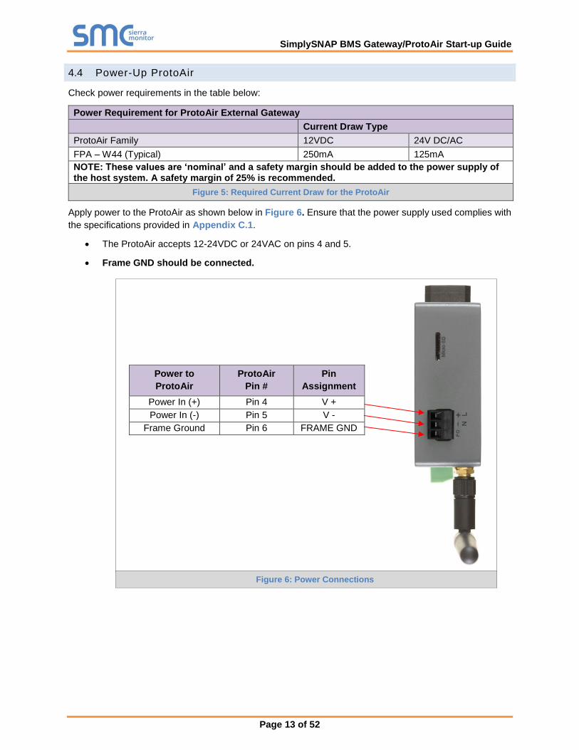
4.4 Power-Up ProtoAir
Check power requirements in the table below:
Power Requirement for ProtoAir External Gateway
Current Draw Type
ProtoAir Family 12VDC 24V DC/AC
FPA – W44 (Typical) 250mA 125mA
NOTE: These values are ‘nominal’ and a safety margin should be added to the power supply of the host system. A safety margin of 25% is recommended.
Figure 5: Required Current Draw for the ProtoAir
Apply power to the ProtoAir as shown below in Figure 6. Ensure that the power supply used complies with
the specifications provided in Appendix C.1.
• The ProtoAir accepts 12-24VDC or 24VAC on pins 4 and 5.
• Frame GND should be connected.
Power to
ProtoAir
ProtoAir
Pin #
Pin
Assignment
Power In (+) Pin 4 V +
Power In (-) Pin 5 V -
Frame Ground Pin 6 FRAME GND
Figure 6: Power Connections

SimplySNAP BMS Gateway/ProtoAir Start-up Guide
Page 14 of 52
5 CONNECT THE PC TO THE PROTOAIR
There are two ways to connect the PC to the ProtoAir, either by Ethernet cable (Section 5.1) or Wi-Fi
Access Point (Section 5.2).
5.1 Connecting to the ProtoAir via Ethernet
First, connect a Cat-5 Ethernet cable (straight through or cross-over) between the local PC and ProtoAir.
5.1.1 Enable Access Through the Local Browser
There are two methods to enable access to the ProtoAir in the local browser, either by changing the
subnet of the connected PC (Section 5.1.1.1) or using the FieldServer Toolbox to change the IP
Address of the ProtoAir (Section 5.1.1.2).
NOTE: Only perform one method or the other.
5.1.1.1 Changing the Subnet of the Connected PC
The default IP Address for the ProtoAir is 192.168.1.24, Subnet Mask is 255.255.255.0. If the PC and
ProtoAir are on different IP networks, assign a static IP Address to the PC on the 192.168.1.xxx network.
For Windows 10:
• Find the search field in the local computer’s taskbar (usually to the right of the windows icon )
and type in “Control Panel”.
• Click “Control Panel”, click “Network and Internet” and then click “Network and Sharing Center”.
• Click “Change adapter settings” on the left side of the window.
• Right-click on “Local Area Connection” and select “Properties” from the dropdown menu.
• Highlight and then click the Properties button.
• Select and enter a static IP Address on the same subnet. For example:
• Click the Okay button to close the Internet Protocol window and the Close button to close the
Ethernet Properties window.
Ethernet Port
Figure 7: Ethernet Port Location

SimplySNAP BMS Gateway/ProtoAir Start-up Guide
Page 15 of 52
5.1.1.2 Changing the IP Address of the ProtoAir with FieldServer Toolbox
• Ensure that FieldServer Toolbox is loaded onto the local PC. Otherwise, download the
FieldServer-Toolbox.zip via the Sierra Monitor website’s Software Downloads.
• Extract the executable file and complete the installation.
• Double click on the FS Toolbox Utility and click Discover Now on the splash page.
• Find the desired gateway and click the Configure Device button (gear icon) to the right of the
gateway information.
NOTE: If connectivity status is green, then the IP Address doesn’t need to be changed (the
ProtoAir is already on the same subnet). Skip to the next section.
• Select Network Settings in the Configure Device window.
• Modify the IP Address (N1 IP Address field) of the gateway Ethernet port.
o Change additional fields as needed
NOTE: If the gateway is connected to a router, the Default Gateway field of the gateway should be
set to the IP Address of the connected router.
NOTE: Do not change the DHCP Server State (N1 DHCP Server State field).
NOTE: If DNS settings are unknown, set DNS1 to “8.8.8.8” and DNS2 to “8.8.4.4”.
• Click Update IP Settings, then click the “Change and restart” button to reboot the Gateway and
activate the new IP Address. See the FieldServer Toolbox and GUI Manual for more information.

SimplySNAP BMS Gateway/ProtoAir Start-up Guide
Page 16 of 52
5.2 Connecting to the ProtoAir Over Wi-Fi Access Point
When the ProtoAir is first powered up, the Wi-Fi Access Point will be enabled allowing direct connection
to the ProtoAir with Wi-Fi.
To connect to the ProtoAir Wi-Fi Access Point:
• Click the icon (found in the bottom-right corner of the computer screen) to open the available
Wireless Network Connections.
• Select the desired ProtoAir and click Connect.
• Enter the Security key. The default is 12345678.
The available Wireless Network Connection menu should now show that the computer is connected to
the ProtoAir.

SimplySNAP BMS Gateway/ProtoAir Start-up Guide
Page 17 of 52
6 UPDATE NETWORK SETTINGS
After setting a local PC on the same subnet as the ProtoAir (Section 5.1 or Section 5.2), open a web
browser on the PC and enter the IP Address of the ProtoAir; the default Ethernet address is
192.168.1.24, the default Wi-Fi access point address is 192.168.50.1.
NOTE: If the IP Address of the ProtoAir has been changed by previous configuration, the
assigned IP Address can be discovered using the FS Toolbox utility. See Appendix A.1 for
instructions.
From the Web Configurator landing page, click the Network Settings tab to open the Network Settings page
for the ProtoAir.
Configure the network settings of the ProtoAir using the following methods:
• When using the Ethernet port to connect to the local network (Section 6.1.2).
• When connecting the ProtoAir to a local wireless access point, configure the Wi-Fi Client Settings
in the ProtoAir (Section 6.1.3).
NOTE: For Wi-Fi Access Point network information see Appendix B.5.
Figure 8: Web Configurator Landing Page – Showing Network Settings Tab

SimplySNAP BMS Gateway/ProtoAir Start-up Guide
Page 18 of 52
6.1.1 Common Settings
The Common Settings make it possible to choose the primary connection when both Ethernet and Wi-Fi
Client connections are available.
NOTE: The default Primary Connection is Ethernet.
To change the primary connection when both Ethernet and Wi-Fi Client connections are available:
• Select the desired option from the Primary Connection drop-down menu.
• Click Save, then click on Refresh to restart the ProtoAir and activate the new settings.
NOTE: If using Wi-Fi Client and not Ethernet, change Primary Connection to Wi-Fi.
Figure 9: Common Network Settings
SimplySNAP BMS Gateway/ProtoAir Start-up Guide
Page 19 of 52
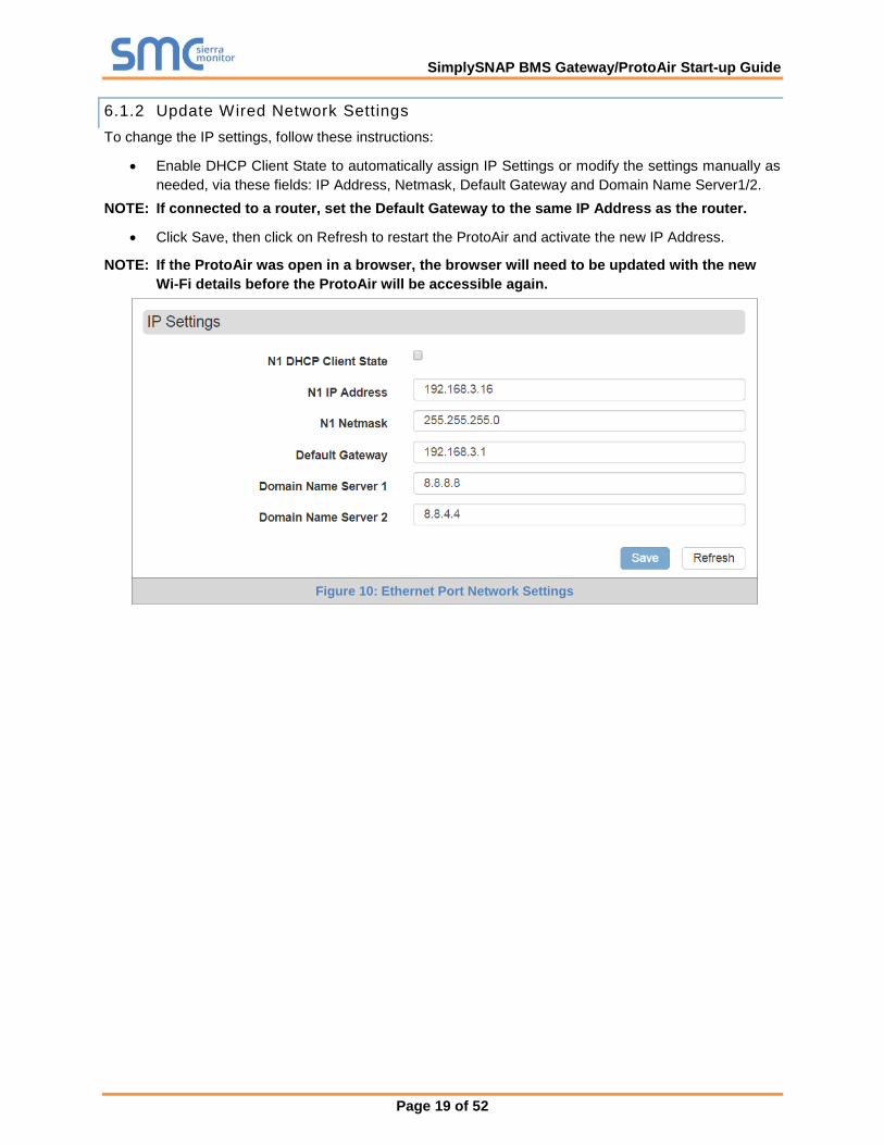
6.1.2 Update Wired Network Settings
To change the IP settings, follow these instructions:
• Enable DHCP Client State to automatically assign IP Settings or modify the settings manually as
needed, via these fields: IP Address, Netmask, Default Gateway and Domain Name Server1/2.
NOTE: If connected to a router, set the Default Gateway to the same IP Address as the router.
• Click Save, then click on Refresh to restart the ProtoAir and activate the new IP Address.
NOTE: If the ProtoAir was open in a browser, the browser will need to be updated with the new
Wi-Fi details before the ProtoAir will be accessible again.
Figure 10: Ethernet Port Network Settings
SimplySNAP BMS Gateway/ProtoAir Start-up Guide
Page 20 of 52
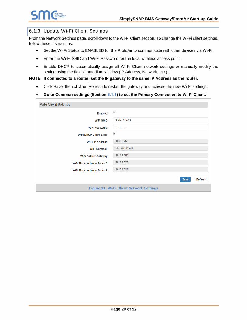
6.1.3 Update Wi-Fi Client Settings
From the Network Settings page, scroll down to the Wi-Fi Client section. To change the Wi-Fi client settings,
follow these instructions:
• Set the Wi-Fi Status to ENABLED for the ProtoAir to communicate with other devices via Wi-Fi.
• Enter the Wi-Fi SSID and Wi-Fi Password for the local wireless access point.
• Enable DHCP to automatically assign all Wi-Fi Client network settings or manually modify the
setting using the fields immediately below (IP Address, Network, etc.).
NOTE: If connected to a router, set the IP gateway to the same IP Address as the router.
• Click Save, then click on Refresh to restart the gateway and activate the new Wi-Fi settings.
• Go to Common settings (Section 6.1.1) to set the Primary Connection to Wi-Fi Client.
Figure 11: Wi-Fi Client Network Settings

SimplySNAP BMS Gateway/ProtoAir Start-up Guide
Page 21 of 52
7 CONFIGURE THE PROTOAIR
7.1 Select BMS Protocol and Configure Settings
• Go back to the Discovery and Configuration tab, and press the BMS Settings button to view/ change
the Building Management System (BMS) Settings.
• Select BACnet/IP, BACnet MS/TP, Modbus TCP/IP or Modbus RTU protocols.
• Edit settings as needed.
• Once completed, click Save and allow the ProtoAir to restart.
Figure 12: Select BMS Protocol
SimplySNAP BMS Gateway/ProtoAir Start-up Guide
Page 22 of 52
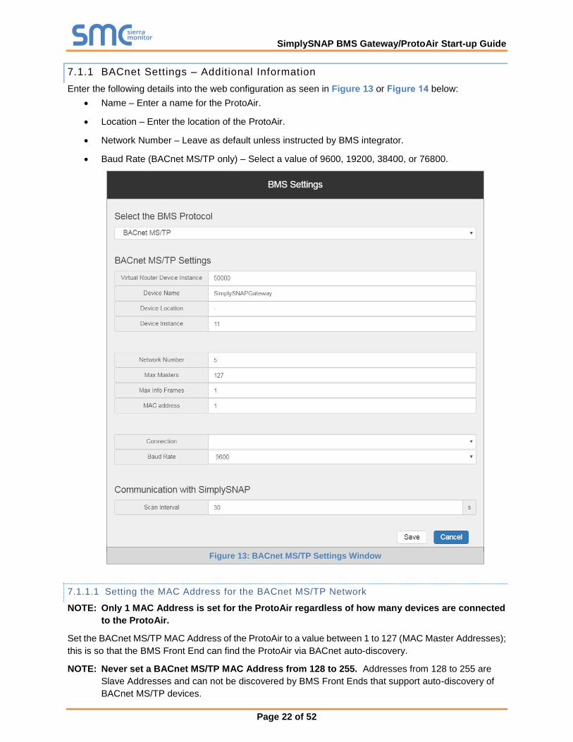
7.1.1 BACnet Settings – Additional Information
Enter the following details into the web configuration as seen in Figure 13 or Figure 14 below:
• Name – Enter a name for the ProtoAir.
• Location – Enter the location of the ProtoAir.
• Network Number – Leave as default unless instructed by BMS integrator.
• Baud Rate (BACnet MS/TP only) – Select a value of 9600, 19200, 38400, or 76800.
7.1.1.1 Setting the MAC Address for the BACnet MS/TP Network
NOTE: Only 1 MAC Address is set for the ProtoAir regardless of how many devices are connected
to the ProtoAir.
Set the BACnet MS/TP MAC Address of the ProtoAir to a value between 1 to 127 (MAC Master Addresses);
this is so that the BMS Front End can find the ProtoAir via BACnet auto-discovery.
NOTE: Never set a BACnet MS/TP MAC Address from 128 to 255. Addresses from 128 to 255 are
Slave Addresses and can not be discovered by BMS Front Ends that support auto-discovery of
BACnet MS/TP devices.
Figure 13: BACnet MS/TP Settings Window

SimplySNAP BMS Gateway/ProtoAir Start-up Guide
Page 23 of 52
7.1.1.2 Set the ProtoAir BACnet Device Instance
NOTE: The Device Instance can be set independently of the site administrator.
• A Device Instance is a BACnet Node-ID which is obtained by the network administrator.
• All the devices connected to the ProtoAir will be under the same BACnet Device Instance.
NOTE: The default BACnet Device Instance is 11.
• The values allowed for a BACnet Device Instance can range from 1 to 4,194,303.
• To assign a specific Device Instance, change the Device Instance value as desired.
Figure 14: BACnet/IP Settings Window
SimplySNAP BMS Gateway/ProtoAir Start-up Guide
Page 24 of 52
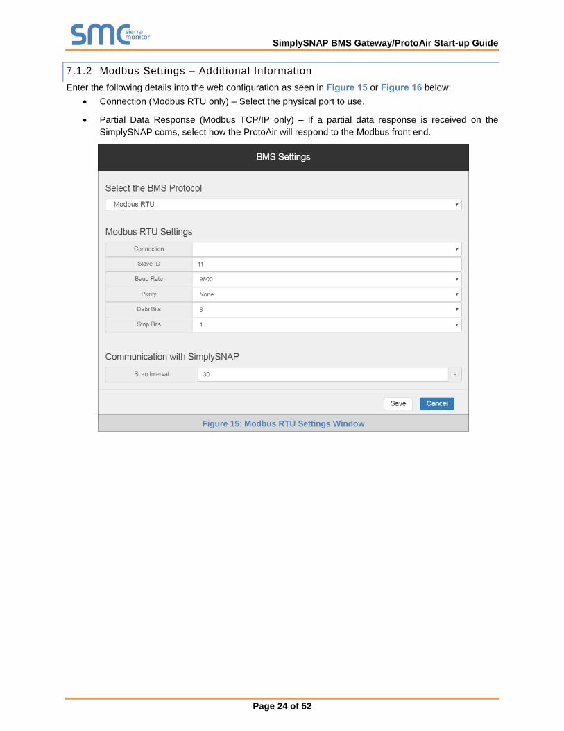
7.1.2 Modbus Settings – Additional Information
Enter the following details into the web configuration as seen in Figure 15 or Figure 16 below:
• Connection (Modbus RTU only) – Select the physical port to use.
• Partial Data Response (Modbus TCP/IP only) – If a partial data response is received on the
SimplySNAP coms, select how the ProtoAir will respond to the Modbus front end.
Figure 15: Modbus RTU Settings Window

SimplySNAP BMS Gateway/ProtoAir Start-up Guide
Page 25 of 52
7.1.2.1 Setting the Modbus Slave ID
When the Slave ID field is entered, the Slave ID Offset will not be used. In this setting, only one Modbus
server node willl be created.
If Slave ID is not used (input a dash [-] into the Slave ID field), the Slave ID Offset will be used to generate
multiple Modbus server nodes.
Figure 16: Modbus TCP/IP Settings Window – Using Slave ID
Figure 17: Modbus TCP/IP Settings Window – Using Slave ID Offset

SimplySNAP BMS Gateway/ProtoAir Start-up Guide
Page 26 of 52
7.2 Discover Devices Connected to the ProtoAir
• Click on “Start Discovery” to enter the network address, port, username and password for the
SimplySNAP Site Controller. (Section 3.2)
• After entering details, click on “Start Discovery” and the discovery progress bar will display.
o Discovery may take a few minutes depending on the number of points to discover
• After the discovery process is complete, the device tree will appear (see Appendix B.8 for device
tree structure details).
Figure 18: Discovery Window
Figure 19: Discovering Devices
SimplySNAP BMS Gateway/ProtoAir Start-up Guide
Page 27 of 52
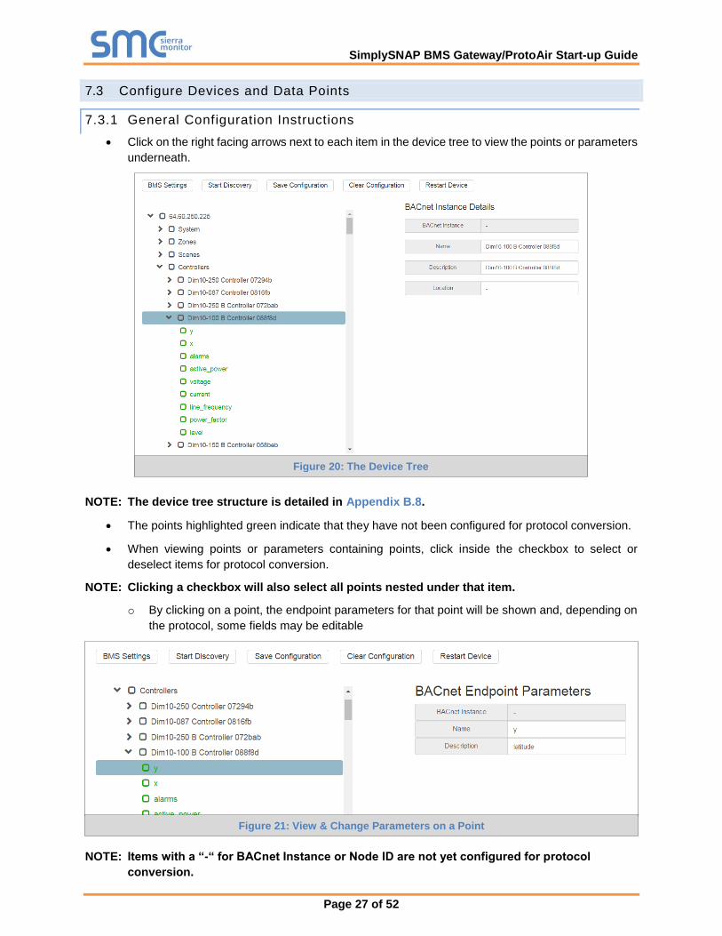
7.3 Configure Devices and Data Points
7.3.1 General Configuration Instructions
• Click on the right facing arrows next to each item in the device tree to view the points or parameters
underneath.
NOTE: The device tree structure is detailed in Appendix B.8.
• The points highlighted green indicate that they have not been configured for protocol conversion.
• When viewing points or parameters containing points, click inside the checkbox to select or
deselect items for protocol conversion.
NOTE: Clicking a checkbox will also select all points nested under that item.
o By clicking on a point, the endpoint parameters for that point will be shown and, depending on
the protocol, some fields may be editable
NOTE: Items with a “-“ for BACnet Instance or Node ID are not yet configured for protocol
conversion.
Figure 20: The Device Tree
Figure 21: View & Change Parameters on a Point
SimplySNAP BMS Gateway/ProtoAir Start-up Guide
Page 28 of 52
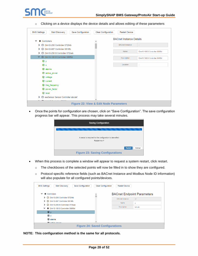
o Clicking on a device displays the device details and allows editing of these parameters
• Once the points for configuration are chosen, click on “Save Configuration”. The save configuration
progress bar will appear. This process may take several minutes.
• When this process is complete a window will appear to request a system restart, click restart.
o The checkboxes of the selected points will now be filled in to show they are configured.
o Protocol specific reference fields (such as BACnet Instance and Modbus Node ID information)
will also populate for all configured points/devices.
NOTE: This configuration method is the same for all protocols.
Figure 22: View & Edit Node Parameters
Figure 23: Saving Configurations
Figure 24: Saved Configurations

SimplySNAP BMS Gateway/ProtoAir Start-up Guide
Page 29 of 52
7.3.2 Modbus Map Window
NOTE: When configuring points for Modbus, an option to view point details from a quick look up
table or CSV file download is also available.
• Click on the IP Address to view the Modbus Node details for the entire configuration or click on a
specific device to view the map for just the selected device.
• To view or download the Modbus mapping click the “Download” or “View” links.
o Click View to open a window that lists the Modbus data points
NOTE: Find specific points using the search bars above each data element.
o Click Download to download a CSV file of the Modbus data points to the local PC’s default
download folder
Figure 25: Modbus Map Window
Figure 26: Saved Configurations

SimplySNAP BMS Gateway/ProtoAir Start-up Guide
Page 30 of 52
7.4 Clearing Configuration
• To clear a configuration, click on “Clear Configuration”. An additional option to clear all other device
configurations is also available.
• After clicking on the Clear & Restart button the window will state “Configuration cleared.
Restarting…”.
• After this process is complete, the ProtoAir will automatically restart.
Figure 27: Clear Configuration Window
SimplySNAP BMS Gateway/ProtoAir Start-up Guide
Page 31 of 52
Appendix A Troubleshooting
Appendix A.1 Lost or Incorrect IP Address
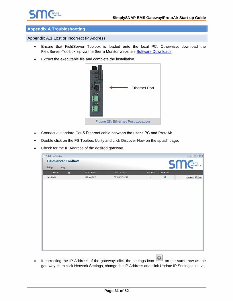
• Ensure that FieldServer Toolbox is loaded onto the local PC. Otherwise, download the
FieldServer-Toolbox.zip via the Sierra Monitor website’s Software Downloads.
• Extract the executable file and complete the installation.
• Connect a standard Cat-5 Ethernet cable between the user’s PC and ProtoAir.
• Double click on the FS Toolbox Utility and click Discover Now on the splash page.
• Check for the IP Address of the desired gateway.
• If correcting the IP Address of the gateway: click the settings icon on the same row as the
gateway, then click Network Settings, change the IP Address and click Update IP Settings to save.
Ethernet Port
Figure 28: Ethernet Port Location
SimplySNAP BMS Gateway/ProtoAir Start-up Guide
Page 32 of 52
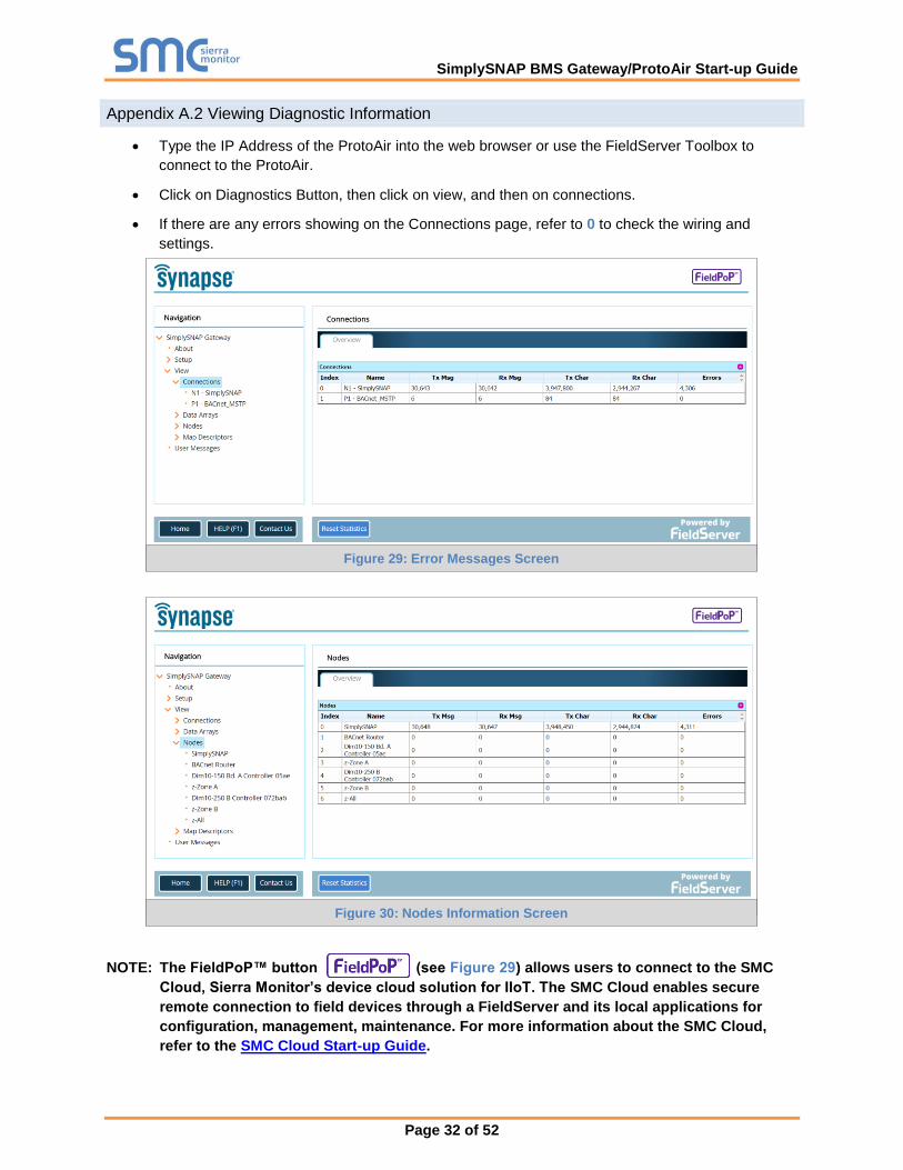
Appendix A.2 Viewing Diagnostic Information
• Type the IP Address of the ProtoAir into the web browser or use the FieldServer Toolbox to
connect to the ProtoAir.
• Click on Diagnostics Button, then click on view, and then on connections.
• If there are any errors showing on the Connections page, refer to 0 to check the wiring and
settings.
NOTE: The FieldPoP™ button (see Figure 29) allows users to connect to the SMC
Cloud, Sierra Monitor’s device cloud solution for IIoT. The SMC Cloud enables secure
remote connection to field devices through a FieldServer and its local applications for
configuration, management, maintenance. For more information about the SMC Cloud,
refer to the SMC Cloud Start-up Guide.
Figure 29: Error Messages Screen
Figure 30: Nodes Information Screen

SimplySNAP BMS Gateway/ProtoAir Start-up Guide
Page 33 of 52
Appendix A.3 Checking Wiring and Settings
• No COMS on the Ethernet side. Check the following:
o Check device address
o Visual observations of LEDs on ProtoAir (Appendix A.4)
o Verify wiring
o Verify the device was discovered (Section 7)
• Field COM problems:
o Visual observations of LEDs on the ProtoAir (Appendix A.4)
o Verify IP Address setting
o Verify wiring
NOTE: If the problem still exists, a Diagnostic Capture needs to be taken and sent to technical
support. (Appendix A.5)

SimplySNAP BMS Gateway/ProtoAir Start-up Guide
Page 34 of 52
Appendix A.4 LED Diagnostics for Communications Between ProtoAir and Devices
See the diagram below for ProtoAir FPA-W44 LED Locations.
Tag Description
SS The SS LED will light if the unit is not getting a response from one or more of the configured devices.
ERR The SYS ERR LED will go on solid indicating there is a system error. If this occurs, immediately report the related “system error” shown in the error screen of the FS-GUI interface to support for evaluation.
PWR This is the power light and should always show steady green when the unit is powered.
TX The TX LED will flash when a message is received on the serial port on the 3-pin connector. If the serial port is not used, this LED is non-operational. TX1 applies to the R1 connection while TX2 applies to the R2 connection.
RX The RX LED will flash when a message is sent on the serial port on the 3-pin connector. If the serial port is not used, this LED is non-operational. RX1 applies to the R1 connection while RX2 applies to the R2 connection.
Figure 31: Diagnostic LEDs
FPA-W44
Diagnostic LEDs

SimplySNAP BMS Gateway/ProtoAir Start-up Guide
Page 35 of 52
Appendix A.5 Taking a FieldServer Diagnostic Capture
When there is a problem on-site that cannot easily be resolved, perform a diagnostic capture before
contacting support so that support can quickly solve the problem. There are two methods for taking
diagnostic captures:
• FieldServer Toolbox:
This method requires installation of the FS Toolbox program. A FS Toolbox diagnostic capture
takes a snapshot of the loaded configuration files and a log of all the communications on the
serial ports over a specified period of time. If the problem occurs over an Ethernet connection,
then take a Wire Shark capture.
• Gateway’s FS-GUI Page:
This method doesn’t require downloading software. The diagnostic capture utilities are embedded
in the FS-GUI web interface. Starting a diagnostic capture takes a snapshot of the loaded
configuration files and a log of all the communications over a specified period of time. This works
for both serial and Ethernet connections.
NOTE: The information in the zipped files contains everything support needs to quickly resolve
problems that occur on-site.
Appendix A.5.1 Using the FieldServer Toolbox
Once the Diagnostic Capture is complete, email it to technical support. The Diagnostic Capture will
accelerate diagnosis of the problem.
• Ensure that FieldServer Toolbox is loaded onto the local PC. Otherwise, download the
FieldServer-Toolbox.zip via the Sierra Monitor website’s Software Downloads.
• Extract the executable file and complete the installation.
• Connect a standard Cat-5 Ethernet cable between the PC and ProtoAir.
• Double click on the FS Toolbox Utility.
Ethernet Port
Figure 32: Ethernet Port Location

SimplySNAP BMS Gateway/ProtoAir Start-up Guide
Page 36 of 52
• Step 1: Take a Log
o Click on the diagnose icon of the desired device
o Ensure “Full Diagnostic” is selected (this is the default)
NOTE: If desired, the default capture period can be changed.

SimplySNAP BMS Gateway/ProtoAir Start-up Guide
Page 37 of 52
o Click on “Start Diagnostic”
o Wait for Capture period to finish, then the Diagnostic Test Complete window will appear
• Step 2: Send Log
o Once the Diagnostic test is complete, a .zip file is saved on the PC
o Choose “Open” to launch explorer and have it point directly at the correct folder
o Contact technical support for delivery instructions and send the Diagnostic zip file

SimplySNAP BMS Gateway/ProtoAir Start-up Guide
Page 38 of 52
Appendix A.5.2 Using FS-GUI
Diagnostic Capture via FS-GUI is only available on FieldServers with a bios updated/released on November
2017 or later. Completing a Diagnostic Capture through the FieldServer allows network connections (such
as Ethernet and Wi-Fi) to be captured.
Once the Diagnostic Capture is complete, email it to technical support. The Diagnostic Capture will
accelerate diagnosis of the problem.
• Open the FieldServer FS-GUI page.
• Click on Diagnostics in the Navigation panel.
• Go to Full Diagnostic and select the capture period.
• Click the Start button under the Full Diagnostic heading to start the capture.
o When the capture period is finished, a Download button will appear next to the Start button
• Click Download for the capture to be downloaded to the local PC.
• Contact technical support for delivery instructions and send the Diagnostic zip file
NOTE: Diagnostic captures of BACnet MS/TP communication are output in a “.PCAP” file
extension which is compatible with Wireshark.

SimplySNAP BMS Gateway/ProtoAir Start-up Guide
Page 39 of 52
Appendix A.6 Wi-Fi Signal Strength
Wi-Fi
<60dBm – Excellent
<70dBm – Very good
<80dBm – Good
>80dBm – Weak
Figure 33: Wi-Fi Signal Strength Listing
NOTE: If the signal is weak or spotty, try to improve the signal strength by checking the antenna
and the ProtoAir position.
Appendix A.7 Factory Reset Instructions
For instructions on how to reset a FieldServer back to its factory released state, see ENOTE - FieldServer
Next Gen Recovery.

SimplySNAP BMS Gateway/ProtoAir Start-up Guide
Page 40 of 52
Appendix A.8 Kaspersky Endpoint Security 10
If Kaspersky Endpoint Security 10 is installed on the user’s PC, the software needs to be modified to allow
the PC to register bridges on SMC Cloud.
NOTE: This problem is specific to KES10, Kaspersky 2017 does not have this problem.
To fix the problem, the ProtoAir (http://192.168.100.85/* in Figure 31) must be set as a trusted URL to the
"Web Anti-Virus"->"Settings" as shown below.
Figure 34: Kaspersky ES10 Settings
Figure 35: Web Anti-Virus Trusted URLs

SimplySNAP BMS Gateway/ProtoAir Start-up Guide
Page 41 of 52
Appendix B Additional Information
Appendix B.1 SSL/TLS for Secure Connection
SSL/TLS (Secure Sockets Layer/Transport Layer Security) is a security technology for establishing an
encrypted connection between a server and a client. This allows the secure transfer of data across
untrusted networks.
Appendix B.1.1 Configuring FieldServer as a SSL/TLS Server
The following example sets the FieldServer to accept a secure Modbus/TCP connection on port 1502.
Appendix B.1.1.1 Simple Secure Server Configuration
Add TLS_Port parameter in the connections section of the configuration file and set to a port number
between 1 – 65535.
Connections
Adapter , Protocol , TLS_Port
N1 , Modbus/TCP , 1502
This configuration sets the FieldServer to accept any incoming connection but will not request a client’s
certificate for verification. This means that the FieldServer end point communication will be encrypted but
not authenticated.
The FieldServer will send an embedded self-signed certificate if one is requested by a connecting client.
NOTE: If a remote client requires a certificate, then request the smc_cert.pem certificate from
Sierra Monitor Technical Support and update the remote client’s authority as per vendor
instructions.

SimplySNAP BMS Gateway/ProtoAir Start-up Guide
Page 42 of 52
Appendix B.1.1.2 Limiting Client Access
In addition to TLS_Port parameter also add Validate_Client_Cert in the connections section of the
configuration file and set it to “Yes”.
Connections
Adapter , Protocol , TLS_Port , Validate_Client_Cert
N1 , Modbus/TCP , 1502 , Yes
The configuration above sets the FieldServer to request and verify a client’s certificate against its internal
authority file before accepting connection. By default, this means the FieldServer will only accept
connections from other FieldServers.
In order to load an authority file so that the FieldServer will accept connections from a chosen list of remote
clients, configure the FieldServer with the following connection settings:
Connections
Adapter , Protocol , TLS_Port , Validate_Client_Cert , Cert_Authority_File
N1 , Modbus/TCP , 1502 , Yes , my_authorized_clients.pem
This configuration has the FieldServer accept connections from clients who have the correct certificate. The
authority file is a collection of client certificates in PEM format. This file can be edited using any text file
editor.
NOTE: Cert_Authority_File is useful only if Validate_Client_Cert is set to ‘Yes’.
Appendix B.1.1.3 Upload the Authority File to the FieldServer
1. Enter the IP address of the FieldServer into a web browser.
2. Choose the ‘Setup’ option in the Navigation Tree and Select ‘File Transfer’.
3. Choose the ‘General’ tab.
4. Click on the ‘Browse’ button and select the PEM file you want to upload.
5. Click on ‘Submit’.
6. When the message “The file was uploaded successfully” appears, click on the ‘System Restart’
button.

SimplySNAP BMS Gateway/ProtoAir Start-up Guide
Page 43 of 52
Appendix B.1.1.4 Certificate Validation Options
If connections must be limited to only a particular domain (vendor devices), include Check_Remote_Host
to specify the domain/host name.
Connections
Adapter , Protocol , TLS_Port , Validate_Client_Cert , Cert_Authority_File , Check_Remote_Host
N1 , Modbus/TCP , 1502 , Yes , my_authorized_clients.pem , SMC
The configuration above tells the FieldServer to only accept connections that have the correct certification
and is coming from the specified host.
The Check_Remote_Host value is synonymously known as common name, host name or domain etc. The
common name can be obtained by the following methods:
• Ask the certificate issuer for the host name.
• Use online tools to decode the certificate (for example: https://www.sslshopper.com/certificate-
decoder.html).
• If the program openssl is installed on the local PC, then run the following command to get the
common name: openssl x509 -in certificate.pem -text –noout
Appendix B.1.1.5 Set up Server Certificate
Make sure the certificate is in PEM format. Otherwise, convert it to PEM format (reference the link below).
support.ssl.com/Knowledgebase/Article
Configure the FieldServer to use a custom certificate as shown below:
Connections
Adapter , Protocol , TLS_Port , Server_Cert_File
N1 , Modbus/TCP , 1502 , my_server_cert.pem

SimplySNAP BMS Gateway/ProtoAir Start-up Guide
Page 44 of 52
Appendix B.1.2 Configuring FieldServer as SSL/TLS Client
The following Node configurations set the FieldServer to open a secure Modbus/TCP connection to Server
at IP Address 10.11.12.13 on port 1502.
Appendix B.1.2.1 Simple Secure Client Configuration
Add Remote_Node_TLS_Port parameter in the nodes section of the configuration file and set to a port
number between 1 – 65535.
Nodes
Node_Name , Node_ID , Protocol , Adapter , IP_Address , Remote_Node_TLS_Port
PLC_11 , 11 , Modbus/TCP , N1 , 10.11.12.13 , 1502
The above configuration sets the FieldServer to connect to a remote server but does not request a server’s
certificate for verification. This means that the FieldServer end point communication will be encrypted but
not authenticated.
If requested by a remote server, the FieldServer will send an embedded self-signed certificate.
Appendix B.1.2.2 Limit Server Access
Add the Validate_Server_Cert parameter to the client node section of the configuration.
……. , Remote_Node_TLS_Port , Validate_Server_Cert
…….. , 1502 , Yes
The above configuration sets the FieldServer to request and verify the server’s certificate against its own
internal authority file before finalizing the connection. By default, this means the FieldServer will only
establish connections to other FieldServers.
……. , Remote_Node_TLS_Port , Validate_Server_Cert , Cert_Authority_File
…….. , 1502 , Yes , my_authorized_servers.pem
The above configuration sets the FieldServer to use a specified PEM file to allow custom server
connections.
The authority file is a collection of server certificates in PEM format. This file can be edited using any text
file editor (such as notepad). When the file has all required certificates, paste it into the PEM formatted
server certificate. Now the FieldServer will connect to a server if it can find the server’s certificate in the
authority file.
NOTE: Cert_Authority_File is useful only if Validate_Client_Cert is set to ‘Yes’.
To upload the Certificate to the FieldServer follow the directions for the authority file in Appendix A.1.1.3.
Appendix B.1.2.3 Certificate Validation Options
Use the Check_Remote_Host element as described in Appendix A.1.1.4.
Appendix B.1.2.4 Set up Client Certificate
Make sure the certificate is in PEM format. Otherwise, convert it to PEM format (reference the link below).
support.ssl.com/Knowledgebase/Article
Configure the FieldServer to use a custom certificate as shown below:
……… , Client_Cert_File
……… , my_client_cert.pem

SimplySNAP BMS Gateway/ProtoAir Start-up Guide
Page 45 of 52
Appendix B.2 Updating Firmware
To load a new version of the firmware, follow these instructions:
1. Extract and save the new file onto the local PC.
2. Open a web browser and type the IP Address of the FieldServer in the address bar.
o Default IP Address is 192.168.1.24
o Use the FS Toolbox utility if the IP Address is unknown (Appendix A.1)
3. Click on the “Diagnostics & Debugging” button.
4. In the Navigation Tree on the left-hand side, do the following:
a. Click on “Setup”
b. Click on “File Transfer”
c. Click on the “General” tab
5. In the General tab, click on “Choose Files” and select the web.img file extracted in step 1.
6. Click on the orange “Submit” button.
7. When the download is complete, click on the “System Restart” button.
Appendix B.3 BACnet: Setting Network_Number for More Than One ProtoAir on the Subnet
For both BACnet MS/TP and BACnet/IP, if more than one ProtoAir is connected to the same subnet, they
must be assigned unique Network_Number values.
On the main Web Configuration screen, update the BACnet Network Number field and click submit. The
default value is 5.
Figure 36: Web Configurator – Network Number Field
SimplySNAP BMS Gateway/ProtoAir Start-up Guide
Page 46 of 52
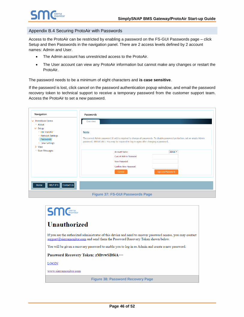
Appendix B.4 Securing ProtoAir with Passwords
Access to the ProtoAir can be restricted by enabling a password on the FS-GUI Passwords page – click
Setup and then Passwords in the navigation panel. There are 2 access levels defined by 2 account
names: Admin and User.
• The Admin account has unrestricted access to the ProtoAir.
• The User account can view any ProtoAir information but cannot make any changes or restart the
ProtoAir.
The password needs to be a minimum of eight characters and is case sensitive.
If the password is lost, click cancel on the password authentication popup window, and email the password
recovery token to technical support to receive a temporary password from the customer support team.
Access the ProtoAir to set a new password.
Figure 37: FS-GUI Passwords Page
Figure 38: Password Recovery Page
SimplySNAP BMS Gateway/ProtoAir Start-up Guide
Page 47 of 52
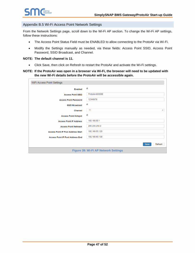
Appendix B.5 Wi-Fi Access Point Network Settings
From the Network Settings page, scroll down to the Wi-Fi AP section. To change the Wi-Fi AP settings,
follow these instructions:
• The Access Point Status Field must be ENABLED to allow connecting to the ProtoAir via Wi-Fi.
• Modify the Settings manually as needed, via these fields: Access Point SSID, Access Point
Password, SSID Broadcast, and Channel.
NOTE: The default channel is 11.
• Click Save, then click on Refresh to restart the ProtoAir and activate the Wi-Fi settings.
NOTE: If the ProtoAir was open in a browser via Wi-Fi, the browser will need to be updated with
the new Wi-Fi details before the ProtoAir will be accessible again.
Figure 39: Wi-Fi AP Network Settings

SimplySNAP BMS Gateway/ProtoAir Start-up Guide
Page 48 of 52
Appendix B.6 Mounting
The ProtoAir can be mounted using the DIN rail mounting bracket on the back of the unit.
Figure 40: DIN Rail
Din Rail Bracket
SimplySNAP BMS Gateway/ProtoAir Start-up Guide
Page 49 of 52
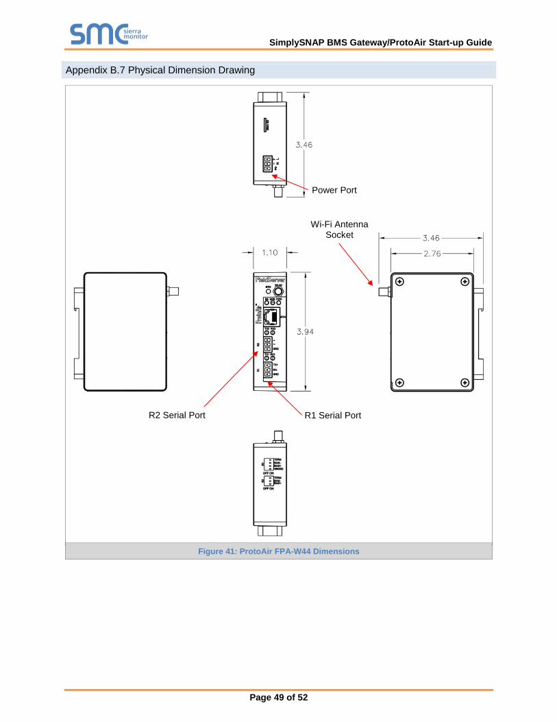
Appendix B.7 Physical Dimension Drawing
Figure 41: ProtoAir FPA-W44 Dimensions
R1 Serial Port
Power Port
Wi-Fi Antenna Socket
R2 Serial Port

SimplySNAP BMS Gateway/ProtoAir Start-up Guide
Page 50 of 52
Appendix B.8 Structure of the Device Tree
The Device Tree is in the following structure:
• ProtoAir IP Address
o Device types
- List of devices connected to this ProtoAir
• List of device parameters
For example:

SimplySNAP BMS Gateway/ProtoAir Start-up Guide
Page 51 of 52
Appendix C Reference
Appendix C.1 Specifications
ProtoAir FPA-W442
Electrical Connections
One 3-pin Phoenix connector with: RS-485/RS-232 port (TX+/RX-/gnd) One 3-pin Phoenix connector with: RS-485 (Tx+/Rx-/gnd) One 3-pin Phoenix connector with: Power port (+/-/Frame-gnd) One Ethernet 10/100 BaseT port
Power Requirements Input Voltage: 12-24VDC or 24VAC Current draw: 24VAC 125mA Max Power: 3 Watts 12-24VDC 250mA @12VDC
Approvals CE and FCC Class B & C Part 15, UL 60950, WEEE compliant, IC Canada, RoHS compliant
Physical Dimensions 4 x 1.1 x 2.7 in (10.16 x 2.8 x 6.8 cm)
Weight 0.4 lbs (0.2 Kg)
Operating Temperature -20°C to 70°C (-4°F to158°F)
Humidity 10-95% RH non-condensing
Wi-Fi 802.11 b/g/n Frequency: 2.4 GHz Channels: 1 to 11 (inclusive)
Antenna Type: SMA Encryption: TKIP, WPA & AES
Figure 42: Specifications
Appendix C.1.1 Compliance with UL Regulations
For UL compliance, the following instructions must be met when operating ProtoAir.
• The units shall be powered by listed LPS or Class 2 power supply suited to the expected operating
temperature range.
• The interconnecting power connector and power cable shall:
o Comply with local electrical code
o Be suited to the expected operating temperature range
o Meet the current and voltage rating for ProtoAir
• Furthermore, the interconnecting power cable shall:
o Be of length not exceeding 3.05m (118.3”)
o Be constructed of materials rated VW-1, FT-1 or better
• If the unit is to be installed in an operating environment with a temperature above 65 °C, it should
be installed in a Restricted Access Area requiring a key or a special tool to gain access.
• This device must not be connected to a LAN segment with outdoor wiring.
2 Specifications subject to change without notice.

SimplySNAP BMS Gateway/ProtoAir Start-up Guide
Page 52 of 52
Appendix D Limited 2 Year Warranty
Sierra Monitor Corporation warrants its products to be free from defects in workmanship or
material under normal use and service for two years after date of shipment. Sierra Monitor
Corporation will repair or replace any equipment found to be defective during the warranty period.
Final determination of the nature and responsibility for defective or damaged equipment will be
made by Sierra Monitor Corporation personnel.
All warranties hereunder are contingent upon proper use in the application for which the product
was intended and do not cover products which have been modified or repaired without Sierra
Monitor Corporation’s approval or which have been subjected to accident, improper maintenance,
installation or application, or on which original identification marks have been removed or altered.
This Limited Warranty also will not apply to interconnecting cables or wires, consumables or to
any damage resulting from battery leakage.
In all cases Sierra Monitor Corporation’s responsibility and liability under this warranty shall be
limited to the cost of the equipment. The purchaser must obtain shipping instructions for the
prepaid return of any item under this warranty provision and compliance with such instruction shall
be a condition of this warranty.
Except for the express warranty stated above, Sierra Monitor Corporation disclaims all warranties
with regard to the products sold hereunder including all implied warranties of merchantability and
fitness and the express warranties stated herein are in lieu of all obligations or liabilities on the
part of Sierra Monitor Corporation for damages including, but not limited to, consequential
damages arising out of/or in connection with the use or performance of the product.