15901-2008 Bms Ubc Bacnet Bms Master 14dec05 Final
95
Building Management Systems (BMS) DESIGN GUIDELINES at the University of British Columbia -.-.-.-.-.-.-.-.-.-.-.-.-.-.-.- Revised: December 14, 2005
Transcript of 15901-2008 Bms Ubc Bacnet Bms Master 14dec05 Final

8/3/2019 15901-2008 Bms Ubc Bacnet Bms Master 14dec05 Final
http://slidepdf.com/reader/full/15901-2008-bms-ubc-bacnet-bms-master-14dec05-final 1/95
Building Management Systems
(BMS)
DESIGN GUIDELINES
at theUniversity of British Columbia
-.-.-.-.-.-.-.-.-.-.-.-.-.-.-.-
Revised: December 14, 2005
8/3/2019 15901-2008 Bms Ubc Bacnet Bms Master 14dec05 Final
http://slidepdf.com/reader/full/15901-2008-bms-ubc-bacnet-bms-master-14dec05-final 2/95
INDEX
FOR THE
BMS GUIDELINE S (INDEX ADDED 2009)
PAGE #
1. OVERVIEW 2
2.1 GENERAL BMS INSTALLATION REQUIREMENTS 6
3.1 GENERAL BMS DESIGN REQUIREMENTS 18
4. BMS EQUIPMENT 22
5. BMS SOFTWARE, DATABASE AND PROGRAMMING REQUIREMENTS 43
6. CBMS SOFTWARE, DATABASE AND PROGRAMMING REQUIREMENTS 47
7. GUIDELINES FOR APPLICATION OF BMS TO TYPICAL HVAC SYSTEMS 52
FIELD TERMINATION SCHEDULES AND SYSTEM SCHEMATICS 127

8/3/2019 15901-2008 Bms Ubc Bacnet Bms Master 14dec05 Final
http://slidepdf.com/reader/full/15901-2008-bms-ubc-bacnet-bms-master-14dec05-final 3/95
University of British Columbia UBC BMS Design Guidelines December 14, 2005
Page 2
1. OVERVIEW
1.1 General
A. The University of British Columbia is a large campus with numerous buildings of variousages. A significant number of these buildings are of a vintage that predates modernmicroprocessor based HVAC control systems and these older building control systems arecontinuously being upgraded. New buildings are also being constructed at the UBC Campuson an on-going basis. To assist in the operation and maintenance of campus buildings, UBCPlant Operations provide centralized monitoring and control of UBC buildings from a centrallocation via microprocessor based DDC controls. To facilitate the centralized BMSmonitoring and control standards have been applied to the selection of BMS equipment andfor the application of BMS installations in buildings. The UBC BMS Design Guidelines serveto identify typical standards for the application of BMS’s in UBC buildings. These DesignGuidelines have also been developed to assist UBC in ensuring that UBC buildings areprovided with high quality BMS installations that fully meet their requirements.
1.2 Application of these BMS Design Guidelines
A. This document is intended to serve as a guideline for the Design of Building ManagementSystem (BMS) installations in buildings at the University of British Columbia (UBC). Theguideline serves to generally identify the existing UBC Campus BMS infrastructure andinstalled components and to record BMS design requirements specific to UBC installations.The UBC Design Guidelines may be used by BMS Designers for guidance in the design of UBC BMS installations but shall not be reproduced, in whole, or part, for inclusion in BMSDesign Specifications, or Tender or Contract Documents. The UBC BMS Design Guidelinesare not Design Specifications and do not include sufficient detail to be used as such. BMSDesigners will be required to include additional detailed information in BMS DesignSpecifications to clearly identify all aspects of the BMS installation.
B. BMS Designs shall be based on sound industry standard practices. BMS Designers shallprovide BMS Designs that have been specifically engineered for the application and shallexercise discretion in the application of these guidelines. All new building construction at
UBC will utilize DDC BMS monitoring and control of building equipment and systems tosome degree. Existing buildings are also being upgraded with retrofits to mechanical andelectrical systems as well as to the building control and monitoring facilities. BMS DesignDocuments shall clearly identify the nature of the BMS installation work and shall include thecontractual documentation and requirements where applicable.
C. All new BMS installations shall comprise equipment, data and data communications that arefully compliant with ANSI/ASHRAE Standard 135-2001 “BACnet”.
1.3 List of Abbreviations
A. The following are a list of abbreviations used throughout these design guidelines and arealso abbreviations used by the University of British Columbia relating to BuildingManagement Systems.
ACC - UBC Auxiliary Control and Alarm CentreANSI - American National Standards InstituteASC - Application Specific Controller ASHRAE - American Society of Heating, Refrigerating and Air-Conditioning EngineersASTM - American Society for Testing MaterialsAWG - American Wire GaugeBMS - Building Management and Control SystemBACnet - Building Automation and Controls Network - ANSI/ASHRAE Standard 135-2001CBMS - Campus Building Management System

8/3/2019 15901-2008 Bms Ubc Bacnet Bms Master 14dec05 Final
http://slidepdf.com/reader/full/15901-2008-bms-ubc-bacnet-bms-master-14dec05-final 4/95
University of British Columbia UBC BMS Design Guidelines December 14, 2005
Page 3
RFI - Radio Frequency Interference
CCF - BMS Central Computer FacilityCCP - Communications Control PanelCPU - Central Processing UnitDCP - Distributed Control PanelDDC - Direct Digital ControlFAS - Fire Detection, Alarm and Communication SystemFTS - Field Termination ScheduleH/O/A - Hand/Off/Auto Motor Control Switch/CircuitHVAC - Heating, Ventilating and Air ConditioningIEEE - Institute of Electrical and Electronics EngineersI/O - Input/OutputJCI - Johnson Controls, Inc.LAN - Local Area NetworkLCD - Liquid Crystal DisplayLED - Light Emitting DiodeLON - Local Operating NetworkLonTalk - The open control networking protocol developed by Echelon CorporationLONWORKS – Echelon’s family of hardware and software productsMACC- BMS Master Alarm and Control CentreNDS - Network Data Server NEC - National Electrical CodeNEMA - National Electrical Manufacturers AssociationOIW - Operator Interface WorkstationPC - Personal Computer POT - Portable Operator WorkstationPIM - Process Interface ModuleRAM - Random Access Memory
RH - Relative HumidityROW - Remote Operator WorkstationRTD - Resistance Temperature DeviceSCU - System 600 Standalone Control Unit DCPSVGA - Super Video Graphics Adapter
UBC - University of British ColumbiacUL - Underwriters Laboratory CanadaUPS - Uninterruptible Power Supply UnitVDU - Video Display Unit
1.4 Existing BMS Facilities
A. There are two separate and autonomous BMS’s installed and operating on the UBCCampus, both with individual central alarm monitoring and control facilities, interconnectingnetwork communications facilities and BMS monitoring and control facilities installed withincampus buildings. BMS installations within individual buildings are configured as stand-alone BMS installations capable of real-time monitoring and control. Each of the stand-alonebuilding BMS installations communicates with central computer equipment at the MACC andAAC in the University Services Building. The existing BMS facilities are as manufactured byJohnson Controls, Inc. (JCI) and as manufactured by Siemens Building Technologies, Ltd.(SBT). The two different BMS’s utilize separate communication network facilities.
B. There are two locations with OIW’s for central BMS monitoring and control. The controlcentres are as follows:
1. MACC located in room number 1003 on the second floor of the UBC Plant OperationsBuilding.
2. ACC located in room number 003 on the ground floor of the UBC Plant OperationsBuilding.

8/3/2019 15901-2008 Bms Ubc Bacnet Bms Master 14dec05 Final
http://slidepdf.com/reader/full/15901-2008-bms-ubc-bacnet-bms-master-14dec05-final 5/95
University of British Columbia UBC BMS Design Guidelines December 14, 2005
Page 4
C. The following is a list of existing Johnson Controls, Inc. BMS facilities and equipment atUBC:
1. Metasys Operator Workstation (OWS) software (Rev. level 12.3) running on aMicrosoft Windows 2000 Professional Operating System PC complete with VDU andarchiving facilities in the MACC.
2. Metasys Operator Workstation (OWS) software (Rev. level 12.3) running on aMicrosoft Windows 2000 Professional Operating System PC complete with VDU in theACC.
3. Metasys Application Data Server (ADX) computer running Metasys ADX software withMicrosoft Windows 2000 Server and Microsoft SQL Server 2000. The server computer is a desktop PC computer. The ADX is the web server for the Metasysextended architecture.
4. Metasys DCP’s and ASC’s installed in distributed standalone building BMSinstallations.
5. Metasys OWS software installed on a laptop computer and configured as a portableoperator workstation. The portable operator workstation (POT) also has the JCIMetasys software (HVACPro) installed for Operator interface to ASC’s.
D. The following is a list of existing Siemens Building Technologies, Ltd. BMS facilities andequipment at UBC:
1. Server PC running Microsoft Windows Server 2003 Operating System and System600 Insight Apogee 3.5 complete with VDU and archiving facilities in the MACC.
2. Seven (7) Apogee Operator Workstations with Client Software running on a MicrosoftWindows 2000 or XP Pro Operating System.
3. Two (2) Apogee Operator Workstations with Client Software running on a MicrosoftWindows 2000 Professional Operating System.
4. Network interconnection and signal conditioning facilities for central networkcommunication with four separate physical network segments.
5. SBT System 600 DCP’s and ASC’s installed in distributed standalone building BMSinstallations.
6. Two (2) Laptop computers with terminal emulation software and application softwarefor Operator direct connect interface to System 600 DCP’s and ASC’s.
1.6 Existing BMS Communication Network Facilities at UBC
A. The JCI Metasys BMS and the SBT System 600 BMS at UBC utilize separate networkcommunication facilities. Existing BMS Network Communications facilities are generally asfollows:
1. JCI Metasys BMS Data Communication within Buildinga. Automation Level communication LAN (N1 Bus) for data communication
between CCP’s/DCP’s (and local OWS’s where applicable) within buildinginstallations utilizes either ArcNet or Ethernet communications. The BMSAutomation Level communication networks within buildings are dedicated BMSnetwork segments and are not shared with other building data communications.
b. Proprietary, dedicated Field Level communications network (N2 Bus) for communication between ASC’s and between ASC’s and DCP’s.
2. JCI Metasys Campus BMS Data Communicationsa. Management Level communication LAN (N1 Bus) utilizes UBC campus
enterprise Ethernet Network for communication between remote building BMSinstallations and the central monitoring and control equipment. The dedicatedstandalone BMS network is interconnected to the UBC Campus EnterpriseNetwork at a location within the building.
3. SBT System 600 BMS Data Communications within Buildinga. Automation Level communication LAN (labelled the “Building Network” or P2
Bus) for data communication between DCP’s (and local OWS’s whereapplicable) within building installations utilizes a proprietary dedicated

8/3/2019 15901-2008 Bms Ubc Bacnet Bms Master 14dec05 Final
http://slidepdf.com/reader/full/15901-2008-bms-ubc-bacnet-bms-master-14dec05-final 6/95
University of British Columbia UBC BMS Design Guidelines December 14, 2005
Page 5
communications network. The BMS primary communication networks withinbuildings are dedicated BMS network segments and are not shared with other building data communications.
b. Proprietary, dedicated Field Level communications network (labelled the “Floor Network”) for communication between ASC’s and between ASC’s and DCP’s.
4. SBT System 600 BMS Campus Data Communicationsa. Management Level communications LAN (Building Network/P2 Bus) for data
communications between campus buildings is via a proprietary communicationsnetwork. The Management Level communications network utilizes copper telephone grade cable between the remote buildings and the UBC telephonecentral exchange in the Henry Angus Building. Signal conditioning and networkinterface equipment is required to transmit the data communications via thetelephone grade lines. There are four System 600 primary communicationnetwork segments at the UBC campus. All of the network segments areconnected to the System 600 Apogee Server. Individual building BMS’s areinterconnected to one of the network segments based on a number of criteriaincluding the building geographical location.
b. There are a number of newer System 600 building installations that utilizeTCP/IP Ethernet data communications over the UBC campus enterpriseEthernet Network for communication between the remote building BMSinstallations and the central monitoring and control equipment. The dedicatedstandalone BMS network is interconnected to the UBC Campus EnterpriseNetwork at a location within the building.

8/3/2019 15901-2008 Bms Ubc Bacnet Bms Master 14dec05 Final
http://slidepdf.com/reader/full/15901-2008-bms-ubc-bacnet-bms-master-14dec05-final 7/95
University of British Columbia UBC BMS Design Guidelines December 14, 2005
Page 6
2. BMS INSTALLATION GUIDELINES
2.1 General BMS Installation Requirements
A. This section of the UBC Design Guidelines identifies minimum requirements for BMS fieldinstallations. BMS designs shall include these requirements and BMS designers shallensure that design specifications include these requirements.
B. BMS installations shall be based on sound industry standard practices that are in compliancewith all applicable codes, statutes and ordinances.
C. Design Specifications for BMS Installations shall provide detailed specifications for the allcomponents of the BMS including equipment, field devices, wire/cable, conduit, pneumatictubing, mounts, terminations, etc.
D. The BMS Designer shall fully coordinate BMS design requirements with the other projectdesign team parties (where applicable). The BMS Designer shall coordinate field panelmounting locations, intended DCP/ASC locations, power supply requirements,communications outlet requirements, etc.
E. The following are general installation guidelines for BMS installations:
1. All equipment and materials furnished shall be new.
2. All equipment and materials shall be cUL and/or UL listed and/or CSA approved whereapplicable. Equipment and components shall be labelled accordingly.
3. Wherever possible all similar components (e.g. temperature sensors, differentialpressure transducers, current transformer/relay combinations, signal transmitters, etc.)in a BMS installation shall be by the same manufacturer.
4. Components shall be provided which are suitable for the intended application.Components shall be capable of maintained operation in the applicable environmentalconditions and operation in contact with the controlled/monitored medium.
5. With the exception of field mounted instrumentation and devices, all BMS componentsshall be installed in field panels. Panels and enclosures shall meet, at minimum, thefollowing requirements:
a. Painted steel panels with hinged locking door. All panels shall be keyed to theUBC standard key.
b. Ventilated to prevent excessive heat build-up, where required.c. Field cabling shall be terminated on terminal stripes. Cable within enclosures
shall be installed in cable trays with snap on covers.d. Internal components shall be installed to allow easy access for diagnostics,
maintenance, removal or replacement.e. Panel or enclosure shall be suitable rated for the environment for which it is to
be installed. Exterior enclosures shall be, at minimum, NEMA-4 rated.
6. Panels and enclosures shall only be located within mechanical rooms or at approvedlocations. Panel locations shall be coordinated during design by the BMS Consultantand shall be identified on project design drawings. For new construction projects theBMCS panel locations shall be identified in the project mechanical design drawings.For retrofit applications the BMCS panel locations shall be identified on building floor plan drawings to be included in the project BMS Specifications/Contract Documents.
7. All components of the BMS shall be Identification tagged. Identification tags shall beplastic lamacoid labels or plastic laminated “luggage style” tags securely fastened to

8/3/2019 15901-2008 Bms Ubc Bacnet Bms Master 14dec05 Final
http://slidepdf.com/reader/full/15901-2008-bms-ubc-bacnet-bms-master-14dec05-final 8/95
University of British Columbia UBC BMS Design Guidelines December 14, 2005
Page 7
g. Field panels.
the end device. Tags shall be of a minimum size of 80 x 25 mm engraved with 12 mmbold lettering. Identification tags shall be provided for, at minimum, the following;
a. Sensors.b. Transmitters.c. BMS controlled valve and damper actuators.d. End-Devices.e. Distributed Control Panels (DCP)’s.f. Application Specific Controllers ( ASC)’s.
8. Warning notices shall be provided at all equipment controlled by the BMS and at allassociated motor starters. The warning notices shall state that the equipment is under the control of the BMS and may start or stop at any time without warning. Providewarning notices at minimum at all MCC’s, at local disconnect switches, at AHU plenumdoors, and electrical motors. UBC Plant Operations shall furnish the warning notices tothe BMS Contractor for use on each project. BMS Contractors shall be instructed toobtain the warning labels from UBC and to return unused labels at the end of theproject.
9. Provide warning notices on all DCP control panel doors indicating that hand held radiotransmitters are not to be keyed within 3 meters or the DCP.
10. All BMS wire and cable and pneumatic control tubing shall be identification tagged.Wire/cable shall be identification tagged at every termination location. Wire/cable andtubing terminating at DCP’s and ASC’s shall be tagged with the DCP/ASC controller termination number. Wire/cable and tubing terminating at field devices shall be taggedwith both the DCP/ASC number and the DCP/ASC termination number. At any splicesor terminal strips between the field device and DCP/ASC, the wiring shall be taggedon both sides of the termination point the same as for a field device termination.
11. 120 VAC power supply sources shall be provided to all BMS field panel and DCPmounting locations. The selection of normal power supply or emergency power supplyfacilities shall be based on project and application specific requirements. In general,
however, BMS DCP’s/ASC’s (and associated network interface equipment) monitoringdesignated building critical alarm points shall be provided with emergency power supplies. The DCP/ASC at which the critical building alarms are terminated shall bedesignated at the “tie-in” panel for the building. Where no emergency power isavailable in the building, the tie-in panel shall be provided with uninterruptible power supply equipment. The BMS tie-in panel is required to remain operational in the eventof loss of normal power supply to the building. The tie-in panel shall continue tooperate in the event of a power supply failure for thirty minutes and shall provide alarmannunciation, monitoring, and control of connected systems/devices from the MACCand ACC. The electrical power supply circuit shall be clearly labelled at the electricaldistribution panel and at the BMS field panel location. As built documentation shalldetail power supply circuit source panels and termination locations.
12. All installations shall be provided to readily allow access for maintenance.
13. All BMS data point value engineering units shall be the International System of Units(SI).
F. Facilities shall be provided for the mounting of UBC Plant Operation Telephone and DataCommunications facilities. The BMS Contractor shall provide the following “blue board”mounting facilities at all BMS field panel and DCP mounting locations:
1. A 560 mm W x 600 mm H x 18 mm T fir plywood intercom mounting board. Thebottom edge shall be 1200 mm from the floor. Each board is to be primed and painted

8/3/2019 15901-2008 Bms Ubc Bacnet Bms Master 14dec05 Final
http://slidepdf.com/reader/full/15901-2008-bms-ubc-bacnet-bms-master-14dec05-final 9/95
University of British Columbia UBC BMS Design Guidelines December 14, 2005
Page 8
with two coats of navy blue enamel. The “blue board” is intended for the installation of UBC Plant Operation Telephones and communication interfaces.
2. A shelf 350 mm deep running the length of each plywood mounting board. The shelf shall be mounted at a 30 Degree angle from the horizontal approximately 1000 mmAFF. The shelf shall include a 25 mm high lip along the bottom end. The shelf shallbe painted to match the mounting board. The shelf shall be hinged and provided withsupport straps which can be removed from the shelf to allow the shelf to fold downwhen not in use. The shelf shall be capable of supporting a laptop computer and BMSrecord documentation for BMS Operator interface work.
3. BMS Data and Telephone Interface facilities including conduit and back boxes shall beinstalled immediately adjacent to the “blue board” mounting facilities.
G. The BMCS specifications shall identify requirements for all work to be provided by the BMSContractor including all boring, saw cutting, fire stopping, sleeves, equipment mounting andsupporting, etc.
2.2. BMS Electrical Installation Requirements
A. The following are minimum requirements related to BMS electrical installations:
1. All installations shall be in accordance with the National Electric Code, the BritishColumbia (BC) electrical code, and all governing codes, statutes and ordinances.
2. With the specific exception identified within this document, all BMS wire and cableshall be installed in conduit.
3. In new construction projects exposed conduit installations are not permitted innormally occupied building spaces. In retro-fit applications exposed conduit shall onlybe allowed in specific applications as approved by the BMS Consultant and UBC.
4. Wire/cable for space temperature sensors, VAV terminal unit damper actuator, zonecoil control valve actuator, VAV terminal unit ASC automation LAN and (where
applicable) 24VAC power supply distribution wiring may be installed in ceiling spaceswithout conduit where code permits. Wire/cable installed in ceiling spaces withoutconduit shall be suitably rated and labelled. Wire/cable shall be securely supportedand installed in a neat and workmanlike manner following building lines. Sleeves shallbe provided for all wire/cable that penetrates wall partitions, concrete slabs, or ratedpartitions.
5. BMS low voltage monitoring and control wiring shall meet the following minimumrequirements;
a. Minimum #20 AWG stranded copper conductors (larger gauge wire/cable shallbe provided where required by BMS equipment and where applications warrante.g. long runs, etc.).
b. Twisted pair conductors.c. All BMS input/output point wire/cable and communication cable shall be
shielded. Non-shielded cables may be approved for BMS input and output fieldpoint wiring following certification from the BMS manufacturer that non-shieldedcables will function satisfactorily for the life of the building and that the use of non-shielded cables will not negatively affect other building systems/cabling.The manufacturers certification shall guarantee to UBC that should it bedetermined that BMS system performance is negatively affected or another building system or equipment is negatively affected due to the non-shieldedcable, the BMS manufacturer shall replace the cable at no cost to UBC.Certification to be obtained for each building application of non-shielded cableprior to approval. All data communication cabling shall be shielded.

8/3/2019 15901-2008 Bms Ubc Bacnet Bms Master 14dec05 Final
http://slidepdf.com/reader/full/15901-2008-bms-ubc-bacnet-bms-master-14dec05-final 10/95
University of British Columbia UBC BMS Design Guidelines December 14, 2005
Page 9
d. BMS wire/cable shall not share conduit with other building wiring. Low voltagecable shall not be installed in conduit with line voltage or higher voltage carryingcable. BMS data communication and network cable shall be installed indedicated conduit and shall not share conduit with any other wire/cable.
6. All wire/cable terminations shall be made at screw type terminal stripes. Wire nutterminations and butt splices shall not be acceptable. Wiring runs shall be continuousruns without splices.
7. All BMS equipment and components shall be grounded to building ground facilities.
8. Coordinate installation of conduit with building structure and other trades. Conduitinstallation above accessible ceilings shall be such that there will be no interferencewith the installation of lighting fixtures, fire protection, air outlets or other devices.Color code all conduit and fittings with a unique color at every junction box and at leastevery 3,000 mm (10 feet) along the conduit.
B. All BMS wiring, conduit, junction boxes, pull boxes, cable tray, etc. shall be provided by theBMS Subcontractor as required for a complete installation. The BMS Contractor shallprovide all required access panels, coring, saw cutting, fire stopping, mounting, etc.
C. The BMS Contractor shall coordinate installation of conduit with building structure and other trades. Conduit installation above accessible ceilings shall be such that there will be nointerference with the installation of lighting fixtures, fire protection, air outlets or other devices. Color code all conduit and fittings with a unique color at every junction box and atleast every 3,000 mm (10 feet) along the conduit. BMS conduit shall be identified by a bluecolour code.
D. BMS shall only be capable of controlling electric motors when the associated hand/off/auto(HOA) motor control switches are in the "auto" position. BMS control shall be wired into theauto circuit of the hand/off/auto motor control circuit only. Where hand/off/auto switches donot exist they shall be provided by the BMS Controls Contractor.
E. Life safety and equipment protection interlocks shall be wired to override equipment
whenever it is in operation.
F. Existing interlocks and override control facilities should typically not be removed or overridden by the application of new BMS control facilities without the specific instruction of the BMS Design Consultant and the approval of UBC Plant Operations.
G. Current transformer and relay combination devices shall generally be used for BMS statusmonitoring of electric motors. There may be applications where other devices are moresuitable. This shall be evaluated by the BMS Design Consultant for the application. BMSstatus monitoring of fractional horsepower motors less than 1/8 h.p. shall be provided byauxiliary contacts at the motor control circuit. The BMS Contractor shall be instructed toutilize spare auxiliary contacts if they exist or to provide new where required.
2.3. BMS Communication Provisions
A. The following minimum requirements shall be provided for UBC telephone system and datacommunication interfaces:
1. Four telephone communication outlets at the designated BMS “tie-in” panel location.Two of these communication outlets may be used by the BMS Contractor for connection to the UBC Campus BMS network. The remaining two communicationoutlets will be utilized by UBC Plant Operations for telephone communications andfuture data communications.

8/3/2019 15901-2008 Bms Ubc Bacnet Bms Master 14dec05 Final
http://slidepdf.com/reader/full/15901-2008-bms-ubc-bacnet-bms-master-14dec05-final 11/95
University of British Columbia UBC BMS Design Guidelines December 14, 2005
Page 10
2. Two telephone communication outlets at all other BMS DCP locations. Thesecommunications outlets will be utilized by UBC Plant Operations for telephonecommunications and future data communications.
3. The BMS telephone and data communication facilities shall be provided complete withsuitable back boxes, cover plates and connection jacks, etc. mounted immediatelyadjacent to the BMS “blue board”.
4. In a UBC new construction project the BMS Designer shall coordinate with theappropriate design team consultants for the provision of the required communicationfacilities to be provided by others. In a retrofit application the BMS Controls Contractor shall provide empty conduit and back boxes complete with pull tapes for the futureinstallation of wire and terminations by others.
2.4. BMS Pneumatic Control Installation Requirements
A. The following are minimum requirements related to BMS pneumatic controls installations:
1. All installations shall be in accordance with applicable codes, statutes and ordinances.All pneumatic controls air tubing shall be specified to comply with minimum operatingtemperatures and pressures.
2. Pneumatic control air tubing installed concealed within walls and concrete slabs shallbe installed in suitable conduit. Pneumatic mains and signal control air lines run inpipe chases, hallway ceiling spaces, etc. shall be installed in conduit or dedicatedcable type tray with cover. Pneumatic control air lines installed within mechanicalrooms may be copper tubing and/or Polyethylene type tubing installed within conduit.Exposed polyethylene tubing will not be permitted within mechanical rooms. AllPolyethylene tubing shall be rated for the installation application and shall be suitablylabelled.
3. In new construction projects exposed conduit installations are not permitted innormally occupied building spaces. In retro-fit applications exposed conduit shall onlybe allowed in specific applications as approved by the BMS Consultant and UBC.
4. Pneumatic control air tubing may be installed in ceiling spaces without conduit wherecode permits. Tubing installed in ceiling spaces without conduit shall be suitably ratedand labelled. Tubing shall be securely supported and installed in a neat andworkmanlike manner following building lines. Sleeves shall be provided for all tubingwhich penetrates wall partitions, concrete slabs, or rated partitions.
5. In retrofit applications three-way switch over valves shall be provided on existingpneumatic control air lines to controlled devices for switching between new BMScontrol and existing pneumatic control facilities. Existing pneumatic control facilitiesshall remain installed and operational until the work of the BMS is complete anddemonstrated to the Owner. The BMS Designer shall specify the requirement for theremoval of redundant pneumatic controls components.
6. BMS pneumatic control air facilities shall meet the following minimum requirements:
a. Tubing shall be installed suitably supported using standard fittings andconnections and shall run parallel to building lines.
b. Tubing shall be installed protected from ambient and outdoor temperatureeffects. Where required tubing shall be installed with stand-offs, insulation, etc.
c. Multiple tubing runs shall be installed run parallel shall be suitably supportedand tie-wrapped in tube bundles.
d. Pneumatic control air tubing shall be terminated with standard fittings at panelmounted devices or at pneumatic bulkhead fittings within panels. Field deviceconnections may be run in steel protective spring or BX conduit.

8/3/2019 15901-2008 Bms Ubc Bacnet Bms Master 14dec05 Final
http://slidepdf.com/reader/full/15901-2008-bms-ubc-bacnet-bms-master-14dec05-final 12/95
University of British Columbia UBC BMS Design Guidelines December 14, 2005
Page 11
e. Rubber grommets shall be provided wherever control tubing passes throughducts or plenum walls.
f. A pressure gauge shall be provided at each tapping off the main air line. If apressure reducing valve is required then the gauge shall be positioned after thevalve.
g. BMS pneumatic control output lines to each controlled device shall be providedwith two minimum 40 mm diameter pressure gauges. The gauges shall bemounted at the DCP/ASC control output location and at the input to the controlactuator.
7. Pilot positioners shall be provided for all BMS controlled pneumatic actuators that arecontrolled in sequence (e.g. mixed air dampers, 1/3 - 2/3 steam valves, etc.).
8. In line desiccant filters shall be provided on all main pneumatic control air linessupplying DCP’s and ASC’s with BMS pneumatic control outputs. The in linedesiccant filters shall be provided in addition to the building mains pneumatic controlair dryer/filter facilities.
9. Refrigerated type air dryers shall be provided on all building pneumatic control supplyair mains. In a BMS retrofit application the existing building pneumatic control air facilities shall be inspected during design phase to ensure that air dryer and filter equipment are installed and operational. If the building is not equipped withsatisfactory pneumatic control air filtration and dryer equipment this equipment shallbe installed as part of the BMS installation project. The following are minimumpneumatic controls air dryer and filtration equipment requirements:
a. Two refrigerant type air dryers shall be provided in a duty/standby configuration.b. Installed in discharge air line from controls air compressor set and storage tank.c. Complete with air inlet and outlet pressure gauges and automatic moisture
removal trap.d. Complete with three-way valve manifold and piped in a duty/standby
configuration to allow the operation of one dryer at a time with the second(standby) dryer valve off and switched off.
e. Installation shall be complete with dual air filtration to remove moisture, oil, and
particulate matter from the controls air supply.f. BMS monitored low pressure alarm indication device. Low pressure alarmcondition shall be annunciated at the BMS NDS and CBMS.
2.5 BMS Installation Training Requirements
A. The BMS Specifications shall specify requirements for CBMS/BMS training to be provided aspart of the work of all CBMS/BMS projects. CBMS/BMS Contractor shall submit an outline of the training courses to be given. The training outline shall be submitted with the initial shopdrawing and submittals packages.
B. Training sessions shall include classroom type instruction and "hands on" instruction andshall be given by the BMS Subcontractor on site using the completed installations. Arrangefor additional meeting room space with the Owner.
C. Provide training tailored to the various Owner operations personnel requirements. Durationand number of training sessions to be determined by the BMS Consultant and shall bespecified to accommodate the installation requirements. Provide training in phases tailoredto the following groups:
1. Basic monitoring and control operations.2. Advanced monitoring and control operations.3. Field maintenance and troubleshooting.

8/3/2019 15901-2008 Bms Ubc Bacnet Bms Master 14dec05 Final
http://slidepdf.com/reader/full/15901-2008-bms-ubc-bacnet-bms-master-14dec05-final 13/95
University of British Columbia UBC BMS Design Guidelines December 14, 2005
Page 12
D. The BMS Contractor shall provide initial basic monitoring and control training to the Ownerspersonnel to provide them with sufficient knowledge of the BMS installations such that theycan use the BMS for the day-by-day monitoring and control of the BMS.
E. The BMS Contractor shall provide advanced supervisor level training on the details of BMS.Provide training related to advanced functions, programming, safety features, integration,database development, network facilities, etc.
F. The advanced BMS training shall, at minimum, cover the following topics:
1. BMS hardware details.2. System software and applications programs.3. CCP and DCP controller software development and installation.4. Graphics and applications program development.5. Calibration and functional testing of the BMS.6. Trouble shooting and replacement of faulty components at CCP, DCP and UC’s.
G. Provide field maintenance and trouble shooting training for the Owner's Maintenance staff onthe operation, calibration, troubleshooting, maintenance and repair of BMS field devicesincluding, but not limited to, all instrumentation, valves and valve actuators, dampers anddamper actuators, thermostats, etc.
I. Training sessions shall be designed on the basis of experience and knowledge of theattendees scheduled to participate and shall differentiate between the requirements of supervisory, operations and maintenance personnel. The training shall be specific to theproject and shall cover, at minimum, the following:
1. Data base features.2. Operating sequence programming.3. Operator interface features.4. Details related to the BACnet device and data object point mapping, identification
naming/numbering, alarm point definitions, etc.5. Other subjects necessary to ensure that the operators, maintenance and supervisory
staffs will be able to operate the BMS without any on-going assistance from any outside
party.
J. The CBMS Contractor shall provide Owner Training on the CBMS monitoring and controlfacilities provided for each project. CBMS training shall be project specific and shall atminimum include the following:
1. Details related to the network interconnection and data communications with theremote BMS.
2. Details related to the point mapping, database development, programming, BACnetBMS device and object identification, point naming, integration, etc.
3. VDU graphics set up and modification.4. Alarm monitoring, display, annunciation and modification facilities.
K. The BMS Subcontractor may provide computer based, self directed training accomplish theportions of the UBC training requirements. Provide on site training for details specific to theparticular BMS installation project (i.e. device locations, sequences of operation, safetydevices, life safety system interlocks, maintenance procedures, etc.). Provide site training for any new products, equipment, devices, and software.
2.6 BMS Documentation Requirements
A. The BMS Specifications shall specify requirements for CBMS and BMS documentation to beprovided as part of the work of all CBMS/BMS projects.
B. The following information shall be included on the cover page for each shop drawing and

8/3/2019 15901-2008 Bms Ubc Bacnet Bms Master 14dec05 Final
http://slidepdf.com/reader/full/15901-2008-bms-ubc-bacnet-bms-master-14dec05-final 14/95
University of British Columbia UBC BMS Design Guidelines December 14, 2005
Page 13
equipment documentation submittal:
1. Project name.2. Date.3. Submittal number and resubmittal number as appropriate.4. Name and address of Architect/Consultant.5. Name and address of Owner.6. Name and address of BMS Subcontractor.7. Name and address of supplier or vendor if appropriate.8. Name of manufacturer.
C. Shop drawings shall be CAD generated, minimum plot size of 11 x 17 inches. Drawings shallinclude diagrams, mounting instructions, installation procedures, equipment details andsoftware descriptions for all aspects of the system to be installed. At minimum, the shopdrawings shall include:
1. BMS topology/network architecture schematic(s).2. Installation drawings and schedules.3. CCP, DCP, UC and other panel layouts, including floor plan location and
interconnection drawings.4. Field instrumentation locations on floor plan drawings.5. Schematic of systems indicating instrumentation locations.6. Installation details.7. Schedule of cabling including details of proposed cable types.8. Composite drawings of all motor starter terminal strips and damper terminal strips
indicating all wiring by all contractors on the motor terminal strip.
D. Equipment submittals shall include design, performance and installation details for all aspectsof the system to be installed. Equipment submittals shall be in hardcover binders with a tableof contents and indexing tabs. At minimum, the equipment documentation submittals shallinclude:
1. Equipment technical data sheets with mounting and installation details.2. The documentation shall include comprehensive and complete details of the
Automation Level data communications, data objects, and devices including address,associated controller type, etc. as required and for the interface to the CBMS. ProvideProtocol Implementation Statements (PICS) for all devices.
3. Details of networks/communications equipment, cabling and protocols proposed.4. Software specifications and descriptions including operating sequences.5. Field sensor and instrumentation specification sheets.6. Damper and actuator specification sheets.7. Valves and valve actuator specification sheets.
E. Provide record documentation in manuals as indicated below:
1. Specifications, maintenance requirements and installation requirements for allhardware components.
2. Record drawings and schedules of the completed installation including location of devices, mounting details, and cabling details.
3. Field Instrumentation and End Device Hardware Manuals4. Software Documentation Manuals.5. Maintenance Manuals.6. Control Drawings.7. Other supporting documentation.
F. Manuals shall be placed in hardcover binders with index page and indexing tabs. Binders areto be as manufactured by ACCO Canadian Company Limited, or approved equal, as follows:
1. 1 and 2 inch binders shall be According "Customizer" Binder 11 x 8 1/2 inch Beige,

8/3/2019 15901-2008 Bms Ubc Bacnet Bms Master 14dec05 Final
http://slidepdf.com/reader/full/15901-2008-bms-ubc-bacnet-bms-master-14dec05-final 15/95
University of British Columbia UBC BMS Design Guidelines December 14, 2005
Page 14
types 13401 and 13403 respectively.
G. Provide Operators' and Supervisors’ Manuals with, at minimum, the following information:
1. Details of all features and functions available to the Operators.2. Details of all alarm, diagnostic, error and other messages. Detail the Operator action to
be taken for each instance.3. Detail special programs provided and provide a complete programming instruction
manual. Detail operation of all software applications.4. Detailed listing of the database for all installed devices.5. Details of all data base management functions and features.6. All details and descriptions shall be in a step-by-step format such that an Operator/
Manager would be able to undertake the respective actions solely on the basis of information provided in the manuals and drawings.
H. Provide hardware manuals that shall include, at minimum, the following:
1. Specifications, maintenance requirements and installation requirements for allhardware components.
2. Record drawings and schedules of the completed installation including location of devices, mounting details, and cabling details.
3. Operating sequences and interlocks.4. Names and addresses of spare parts suppliers.
I. Provide field instrumentation and end device manuals that shall include, at minimum, thefollowing:
1. Control Drawingsa. Description of the point identification tag format used.b. All applicable point termination diagrams i.e. typical wiring and termination of all
field devices, controllers and networks.c. Riser Diagram with equipment listed on opposing page - see specimen in
Appendix 1.d. Network architecture diagram.
e. System drawing for each mechanical and electrical system with equipment listand sequences of operation on opposing page for easy reference.2. Control drawings shall be record drawings for the completed installation including the
following:a. Location reference to mechanical drawing number and adjacent grid line number
for instrumentation.b. Location of conduit, tubing and wiring.c. Details of process interface unit termination.d. Details of BMS controlled valves, dampers and actuators including normal
position (open or closed), operating spring/voltage/current ranges and use of pilotpositioners.
3. Sequences of operation and interlocks shall be provided on the "as-built" drawingssuch that a single drawing will enable easy cross-reference to the sequences andassociated field equipment, instrumentation and interlocks.
J. Provide Software documentation manuals that shall include, at minimum, the following:
1. System programming supervisor manuals.2. Complete programming instruction and reference details.3. Application software program information.4. Sequences of operation program flowcharts provided in plastic sleeves within the
manual.5. Control Sequence
a. Full description to support all BMS monitored and controlled systems andcontrollers. Provide in plastic sleeves within the manuals. Printout of control

8/3/2019 15901-2008 Bms Ubc Bacnet Bms Master 14dec05 Final
http://slidepdf.com/reader/full/15901-2008-bms-ubc-bacnet-bms-master-14dec05-final 16/95
University of British Columbia UBC BMS Design Guidelines December 14, 2005
Page 15
language statements, complete with detailed comment lines to enable the Owner to undertake changes to sequences without vendor support. Comment linesshall be provided at the beginning of each program to identify the use andfunction of all variables.
6. Point Reportsa. Log of all point identification names and descriptors.
7. Printout of the BMS point database for all installed and calculated points.8. Other relevant software information.
K. Provide maintenance manuals that shall include, at minimum, the following topics:
1. Maintenance, calibration and installation details for all instrumentation, valves, dampersand actuators furnished under this Subcontract.
2. Maintenance instructions for all BMS hardware equipment including but not limited toCCP, DCP, UC, distributed DDC controllers, modems, printers, ROW, etc.
L. Provide one sharp, clean photocopy of each new or revised drawing, schedule or preparedinstruction sheet to the Owner for microfilming. Maximum size for any sheet is 11 x 17inches. Drawings shall be on 11" x 17" sheets. The title block of each drawing shall haveprovision for a UBC project number and UBC drawing number.
M. Documentation shall be neatly typed or printed on 8 1/2 x 11 inch heavy bond or offset bookpaper. Page quality must be such as to ensure good microfilm reproduction.
N. Provide a copy of each as-built system drawing in 8½" x 11" drawing format and laminated inplastic. A set of laminated "as-built" drawings shall be provided at each CCP and DCPcontroller location. Laminated as-builts for VAV terminal unit controllers shall be provided atthe CCP they are connected to. Each set of laminated "as-built" drawings shall be heldtogether by a metal ring through a grommet hole in the top left hand corner of each drawing.The ring shall be attached to approximately 3 metres of light duty chain, which shall in turn besecurely fastened to the intercom mounting board at the same location as the associatedCCP. A hook shall be provided in the intercom mounting board on which to hang thedrawings by the metal ring.
O. Manuals shall be provided in hard covered loose leaf binders with index pages and indexingtabs. Binders are to be as manufactured by ACCO Canadian Company Limited, or approvedequal, as follows:
1. 1 and 2 inch binders shall be According "Customizer" Binder 11 x 8 1/2 inch Beige,types 13401 and 13403 respectively.
P. Manuals shall be updated whenever the Subcontractor makes changes to the Work.
Q. Comply with and additional project requirements for documentation.
R. Record drawings shall be CAD generated and shall include, at minimum, the following:
1. Details required by the shop drawings.2. Final locations and point ID for each monitored and controlled device.
S. Provide one (1) complete set of all record documentation in printed hardcopy and one (1)complete set of all record documentation in .pdf electronic computer data file format.
T. All BMS and CBMS Record Documentation shall be provided in electronic .pdf file format ona CD or DVD.
2.7 BMS Installation Commissioning and Testing
A. BMS specifications shall clearly specify the requirements for Contractor testing and

8/3/2019 15901-2008 Bms Ubc Bacnet Bms Master 14dec05 Final
http://slidepdf.com/reader/full/15901-2008-bms-ubc-bacnet-bms-master-14dec05-final 17/95
University of British Columbia UBC BMS Design Guidelines December 14, 2005
Page 16
commissioning of the BMS including test documentation and requirements for testing anddemonstration with other project commissioning personnel and the BMS design consultant.
B. The BMS Subcontractor shall conduct full end-to-end testing and commissioning of the BMSinstallations and the overall monitoring and control of the building systems. , BMS Contractor testing shall include the monitoring and supervisory control and data communications with theassociated campus NDS.
C. The BMS Subcontractor shall undertake joint testing of the BMS integration with the CBMSwith the CBMS Integration Contractor. The BMS Specifications shall specify requirements for the joint BMS/CBMS Contractor Testing and Commissioning.
D. The BMS Contractor shall perform a complete and detailed operational check of each BMScomponent. Tests shall be documented on Contractor Commission Record Sheets. TheOwner, Consultant and Engineer shall undertake such random testing as the Owner,Consultant and Engineer considers necessary to verify the acceptability of the components.
E. Point to point checks shall be proven from the field device/interface operation to thecontroller/outstation and from the controller to the presentation of the point on the graphics.The results from the point-to-point tests shall be submitted for approval.
F. Point to point checks shall verify (at minimum) the following:
1. Correct location of the field device for the application.2. Correct installation of the control device/interface with reference to the manufacturer’s
literature and check that sufficient access has been provided for maintenance.3. That the control device has the correct range for the application, that the range is
correctly entered in the controller and is correctly engineered on the operator'sterminal.
4. Correct operation of the controls device/interface, including any associated alarm andalarm text.
5. Correct installation of each valve and damper actuator, and ensure that each valve anddamper actuator is stroked correctly when checked against the BMS output.
6. Calibration of the control device.
7. Labels provided on the control devices and mechanical equipment is correct.
G. Systems testing shall commence once all component testing has been successfullyundertaken and approved by the Consultant.
H. System testing shall be undertaken by the BMS Subcontractor and the BMS Subcontractor shall complete and submit the BMS Contractor Commission Record Sheets. The followingshall be demonstrated as a minimum:
1. Each and every point on the system including calibration checks and the stroking of actuators.
2. All dynamic graphics comply with the mechanical and control specifications.3. All system programs comply with the specification under the normal modes of
operation, emergency power, building fire detected and fireman's override operatingmodes.
4. All system alarms comply with the specification.5. System stability.6. Dynamic tests to prove control stability and those environmental conditions are being
maintained.
I. The Consultant’s verification tests shall be performed by the BMS Subcontractor and shallbe witnessed by the Consultant who shall complete the Consultant’s portion of the systemperformance verification test sheets as each test is successfully undertaken. The BMSSubcontractor shall remedy any deficiencies that are observed during the system

8/3/2019 15901-2008 Bms Ubc Bacnet Bms Master 14dec05 Final
http://slidepdf.com/reader/full/15901-2008-bms-ubc-bacnet-bms-master-14dec05-final 18/95
University of British Columbia UBC BMS Design Guidelines December 14, 2005
Page 17
J. Integrated BMS/CBMS joint systems tests shall be undertaken to demonstrate that theinteraction between the individual building BMS and the CBMS meets the UBCrequirements. The BMS Subcontractor shall participate in joint verification of the integratedsystems and cooperate with the Owner in the demonstration of the integrated systems.
K. The BMS Specifications shall specify the requirements for the BMS/CBMS integration jointsystems verification. The BMS/CBMS Integrated System Verification shall include thefollowing minimum requirements:
performance verification tests and shall be re-tested as required to demonstrate satisfactoryperformance and compliance with the specifications.
1. Test all BMS monitored and controlled field devices, BMS data points and all BMSinput and output points. CBMS monitored data point values shall be verified againstactual field device position/state and compared to BMS values to ensure both BMS andCBMS values are the same.
2. CBMS override control of all BMS output points and control data points shall beverified.
3. BMS network and controller device status and data communications status areaccurately monitored at the CMBS. Alarms for failed controllers and failed datacommunications are annunciated.
4. BMS data values displayed on dynamic system graphics or in tabular data format at theCBMS are functional and accurate.
5. CBMS operator control of BMS control output points and control data points arefunctional via the dynamic graphic interface.
6. CBMS facilities for operator adjustment of alarm definition parameters and thresholds,set point adjustment, control parameter adjustments, point trend initiation andmodification to trends, etc. are fully functional.
7. The CBMS performance requirements for the monitoring and control of BMS data andfield devices meet the UBC requirements.
8. BMS device addressing and identification definitions are compatible and identical andthe addressing scheme meets with UBC requirements.
9. Point naming used is compatible and conformal with the UBC requirements.
L. Test results shall be documented using test sheets. The test sheets shall be prepared inan appropriate format for the various categories of component and system to be tested.It is the responsibility of the BMS Subcontractor to provide test verification sheets for each component and system that accurately reflect the sequences of operation andappropriate data for the components and systems
M. All test documentation shall be maintained in electronic format and in hard copy.

8/3/2019 15901-2008 Bms Ubc Bacnet Bms Master 14dec05 Final
http://slidepdf.com/reader/full/15901-2008-bms-ubc-bacnet-bms-master-14dec05-final 19/95
University of British Columbia UBC BMS Design Guidelines December 14, 2005
Page 18
3. BMS DESIGN GUIDELINES
3.1. General BMS Design Requirements
A. BMS installations at UBC buildings shall be turnkey installations operating fully standalone.
B. All BMS shall conform to the most recent revision of the ANSI/ASHRAE Standard 135including all issued addenda, at minimum, at the Management data communication networklevel as defined within these guidelines. All BMS devices shall implement the functionalitydetailed in the BACnet Standard “Device Profiles”. With the exception of the JohnsonControls Inc. Metasys System and the Siemens Building Technologies System 600 products,the BMS shall also be BACnet compliant at the Automation data communication networklevel.
C. All new BMS installation designs shall identify the requirement for two (2) separate scopes of work packages. The BMS scope of work packages shall include the following:
1. Standalone Building BMS Installation.2. BMS Integration into the Campus BACnet BMS.
D. The existing Siemens Building Technologies System 600 Apogee System will be upgradedby UBC to incorporate the Siemens “BACnet Option” server software. The Siemens System600 Apogee with BACnet Option software, server computer and operator workstations shallbe the Campus Building Management System (CBMS). The CBMS shall be compliant withthe requirements defined for a BACnet Operator Workstation Device (B-OWS). The CBMSshall provide centralized operator interface for monitoring and supervisory control of theindividual building BMS.
E. The UBC Campus BMS (CBMS) shall remotely monitor the individual building BMS and shallhave supervisory control of building BMS facilities using BACnet over IP datacommunications. The CBMS Contractor shall, as part of a separate contract, provide pointcapture, mapping and configuration of the BMS into the CBMS. The BMS Contactor shallprovide assistance and cooperation in the integration of the BMS into the CBMS. Prior toacceptance of the BMS at the individual building project, the BMS Contractor shall prove that
all specified points are available to the CBMS Contractor for the integration to the CBMS andshall provide all project documentation.
F. The BMS Specifications for each building BMS project shall specify the requirement for theBMS Contractor/Manufacturer to provide all hardware and software required for the CBMS tocommunicate with the BMS via BACnet IP on the UBC campus WAN. Facilities to beprovided shall include any manufacturer specific software tools required for programming,point mapping, configuration, etc. of building BMS data points.
G. All BMS installations shall have a network data server computer with associated BMSmanufacturer application software installed and running located in the BMS MACC room inthe University Services Building. The NDS shall be rack mounted in standard 19 inch rackequipment. The NDS shall be provided by the associated BMS Contractor complete with allmanufacture specific BMS operator interface software for programming, databasedevelopment, data archiving and storage, and controller program backup and restorefacilities. NDS mounting rack shall be provided by UBC. The NDS shall be provided withfunctionality detailed in these documents. The dedicated NDS shall communicate with theindividual building BMS’s over the UBC Management Level WAN. Data communicationsshall be BACnet/IP. Any BMS installation provided for a UBC building shall have a NDSdedicated to BMS equipment and installations of the same manufacturer. The manufacturer specific NDS shall be installed on site and communicating with the campus WAN prior to anyproposed building installation of products from any BMS manufacturer.
H. UBC building BMS installations shall be specified to include all project design,documentation, training, installation work, software, database and logic programming, WAN

8/3/2019 15901-2008 Bms Ubc Bacnet Bms Master 14dec05 Final
http://slidepdf.com/reader/full/15901-2008-bms-ubc-bacnet-bms-master-14dec05-final 20/95
University of British Columbia UBC BMS Design Guidelines December 14, 2005
Page 19
interconnection, testing, commissioning, warranty, project management and tradecoordination work as required for a fully functional, standalone, turnkey BMS. The individualbuilding BMS installation Contractor work shall include coordination and documentation workfor the integration of the BMS into the CBMS via BACnet data interface by other contract.Installations shall in no way negatively affect existing BMS installations and existing campusBMS performance.
I. BMS installations shall be provided which incorporate BMS equipment and network facilitiesin compliance with the requirements identified in these guidelines. The BMS designer shallspecify detailed BMS equipment requirements and BMS network architecture requirementsin the BMS Design Specifications. BMS equipment and data communication networkspecifications shall incorporate good BMS engineering, design, and application practises andshall incorporate the UBC BMS Design Guideline requirements.
J. BMS installations in UBC buildings shall incorporate the following minimum requirements:
1. Equipment shall be approved components as manufactured by one of the UBCapproved BMS Manufacturers and shall be in compliance with the UBC BMS DesignGuidelines.
2. Management and Automation Level communication LAN’s shall be provided to ensurethe following:a. The failure of a DCP shall not affect the operation of other operating DCP. UC’s
supervised by the failed DCP shall continue to function and shall controlassociated equipment according to specified failure routines. Whereinformation in the failed DCP is used by other DCP’s, UC’s, buildings, routines,etc. the non-availability of the information shall be alarmed and alternate controlstrategies shall be automatically initiated.
b. The failure of an UC shall not affect the operation of other operating UC or DCP.c. All BMS monitored and controlled points associated with an individual HVAC
System or equipment shall be terminated in the same UC or DCP. It is notacceptable for BMS monitored and controlled points associated with anindividual system to be terminated at separate distributed DCP’s or UC’s. Allrequired logic programming and point database facilities associated with anindividual building system shall reside in the same UC or DCP to which the
system input/output points are terminated. It is not acceptable for logicprogramming and database facilities required for BMS monitoring and control of a building system to reside in a DCP or UC other than to which the systeminput/output points are terminated in.
d. UC’s controlling space terminal units (e.g. VAV terminal units, fan poweredterminal units, etc.) shall reside on the same automation LAN as the UC that iscontrolling the associated air handling unit. If an AHU is controlled directly by aDCP, the UC’s controlling space terminal units shall be supervised by that DCP.
3.2 BMS Subcontractor and System Qualifications
A. BMS’s to be provided for any UBC building installations shall be products as manufacturedby one of the following manufacturers:
1. Delta Controls - ESC Automation2. Johnson Controls, Inc. Metasys Extended Architecture System.3. Siemens Building Technologies, Ltd. System 600.
B. BMS standalone building installations shall be provided by one of the following UBCapproved BMS installation contractors who shall install products of one of the aboveapproved manufacturers:
1. ESC Automation – Delta Controls2. Johnson Controls, Inc. – Johnson Controls Metasys Extended Architecture3. Siemens Building Technologies – System 600 BACnet Option

8/3/2019 15901-2008 Bms Ubc Bacnet Bms Master 14dec05 Final
http://slidepdf.com/reader/full/15901-2008-bms-ubc-bacnet-bms-master-14dec05-final 21/95
University of British Columbia UBC BMS Design Guidelines December 14, 2005
Page 20
3. Have successful project experience on similar projects for a minimum period of five (5)years.
C. BMS installations shall be provided by BMS Contractors who meet the followingrequirements:
1. Must have been in operation in the BMS industry in the City of Vancouver area for aminimum of 10 years.
2. Employ qualified staff in the Vancouver area capable of undertaking a complete BMSinstallation project and to provide routine and emergency maintenance on all elementsof the BMS.
4. Have local service and support facilities for the total BMS. BMS Contractor shall haveservice and support facilities available to UBC 24 hours per day, 7 days per week.
5. Have local, or access to, supplies of BMS components with a maximum deliveryperiod of 24 hours.
D. Work and services for the integration of standalone building BMS’s into the Siemens System600 Apogee Campus Building Management System (CBMS) shall be provided by SiemensBuilding Technologies. BMS design specifications shall detail the work to be provided for theintegration of the building BMS into the Siemens System 600 BMS.
E. BMS facilities to be provided for UBC building installations shall be fully compatible with theexisting installed central monitoring and control facilities, network communications facilities,and with other UBC building BMS installations.
F. All BMS DCP’s, UC’s, OIW’s where applicable, and other BMS Manufacturer specificequipment within a building shall be manufactured by the same manufacturer. All HVAC andbuilding services monitoring and control shall be provided by BMS facilities from one of theapproved UBC BMS manufacturers. In applications where HVAC system controls within anexisting building are being retrofitted and BMS facilities of any of the approved BMSmanufacturers exist within the building, BMS facilities shall be provided by the manufacturer of the BMS equipment already installed. The retrofitted BMS installation shall be provided tointerconnect the new renovation work into the existing building and campus BMS facilities.
G. BMS DDC controllers shall be products manufactured by a company that is an activeCorporate Member of the BACnet Manufacturers Association (BMA).
H. All BMS products proposed for installation on a UBC project shall have been previouslydemonstrated to UBC Plant Operations satisfaction and approved by UBC Plant Operationsprior to being listed as an approved bidder. Any BMS product/equipment for which there isnot a significant existing installation on campus of products from the same manufacturer thatis successfully integrated with the CBMS shall be fully demonstrated to UBC’s satisfactionand approved by UBC Plant Operations prior to being considered as an approved product.
3.3 BMS Network Architecture and Communications Requirements
A. The CBMS and the individual building BMS systems shall be based on multiple tier/level datacommunication networks utilizing different network communications technologies. TheCBMS and the individual building BMS system architecture shall comprise of three layers asdefined within these documents.
B. BMS design specifications shall detail the data communications network facilities to beprovided and the contracting party responsible for providing the work.
C. The CBMS/BMS architecture shall comprise the following network layers:
1. Management Level (by CBMS and BMS Contracts):a. A Wide Area Network (the UBC Campus WAN) shall provide a means of
interoperable communication between the CBMS and the individual building

8/3/2019 15901-2008 Bms Ubc Bacnet Bms Master 14dec05 Final
http://slidepdf.com/reader/full/15901-2008-bms-ubc-bacnet-bms-master-14dec05-final 22/95
University of British Columbia UBC BMS Design Guidelines December 14, 2005
Page 21
BMS using BACnet/IP. This WAN is hereafter referred to as the ManagementLevel Network. The Management Level Network shall provide a means bywhich the building systems throughout the UBC facilities can exchange data inthe form of BACnet data objects. The Management Level Network shall beBACnet/IP over Ethernet and shall be such that an operator with the requiredaccess level shall be able to undertake monitoring and control functions for anyof the integrated BMS buildings.
b. It shall be the responsibility of each BMS building contractor, to ensure that allBMS system data is available at the Management Level Network. The intentis that the CBMS shall be able to automatically read this data from the networkusing the BACnet automatic “find new objects” features. Each BMS buildingsystem contractor shall provide comprehensive and complete documentationregarding the installed BACnet devices, device address, controller type,databases and other pertinent information to the Owner and to the CBMScontractor. BMS Specifications shall specify the inform
c. Each BMS system shall have a dedicated NDS installed at the UBC MACC.The NDS shall be dedicated to campus building BMS’s of the samemanufacturer product. The NDS shall have terminal service capabilities with“Thin Client” operator interface or shall employ “web services” technology suchas Microsoft .Net technology with web browser based operator interface. TheNDS shall communicate with the individual building BMS’s over the BMSManagement Level via BACnet/IP. The NDS shall have manufacturer specificapplication software for operator interface. The NDS shall be configured for archiving and data storage of all associated BMS controllers and devices andfor manufacturer specific controller programming, trouble shooting, data entry,configuration software tools, etc. It is not intended that the NDS be configuredas the central operator monitoring and control workstation.
d. The NDS shall have Terminal Service capabilities with Thin Client operator interface, or equivalent, such that all applications software resides at theterminal servers and the entire UBC facilities are covered by a single softwarelicense regardless of the number of Personal Computers that are accessingNDS via the Management Level Network at any point in time.
e. The existing Siemens Building Technologies System 600 Apogee with BACnetOption server computer and application software shall be the operator interface
for supervisory monitoring and control of the building BMS systems. TheSiemens Building Technologies System 600 Apogee Server computer,application software and associated management level WAN facilities shall bethe Campus Building Management System (CBMS).
f. The CBMS shall be in conformance with the requirements and functionalitydetailed in ANSI/ASHRAE Standard 135 (BACnet) for a BACnet Operator Workstation (B-OWS). The CBMS shall have terminal service capabilities with“Thin Client” operator interface. The CBMS shall communicate with theindividual building BMS’s over the BMS Management Level via BACnet/IP.CBMS applications software shall run on the existing Siemens BuildingTechnology Apogee NDS server computer installed at the UBC MACC. TheCBMS workstations, including the Portable Operator Workstations (POT), shallbe Thin Clients operating through a Virtual Private Network (VPN). It shall bepossible to add access from a remote location by modem and/or via the Web.
g. The Operator Interface Workstations (OIW) that serve the CBMS and BMSshall be resident on the Management Level Network, not the BMS AutomationLevel. If an OIW is required within a remote building, the CBMS contractor shall provide it under a separate contract.
h. The Management Level Network communications, without exception, shall beBACnet/IP. It is intended that there be a single point of interface between abuilding BMS and the Management Level Network (UBC WAN). If multipleCCP are required in a building due to Automation Level node quantities or limitations of CCP capabilities, the BMS Contractor shall add the additionalCCP as an extension of the Management Level Network within the school.

8/3/2019 15901-2008 Bms Ubc Bacnet Bms Master 14dec05 Final
http://slidepdf.com/reader/full/15901-2008-bms-ubc-bacnet-bms-master-14dec05-final 23/95
University of British Columbia UBC BMS Design Guidelines December 14, 2005
Page 22
The BMS Contractor shall provide Management Level network facilities withinindividual buildings.
i. The demarcation point between the CBMS and the building BMS shall be theBMS CCP connection to the WAN data outlet within the building. The BMSContactor shall make the final terminations with supervision from UBC.
2. Automation Level (by the BMS Contract):
a. The Communication Control Panels (CCP) shall be part of the BMS. CCP shallbe software programmable and shall incorporate BACnet/IP to BACnet/MS/TProuters between the Management Level Network and the BACnet controllerson the Automation Level Network.
b. The Automation Level shall primarily include the DDC controllers that interfacewith the field sensors and final control elements. It is anticipated that there willbe two types of DDC controller within the CBMS architecture:
i. Distributed Control panels (DCP).ii. Unitary Controllers (UC).
c. DCP controllers shall be fully programmable controllers and shall have an I/Ocapability to handle major types of equipment such as air handling units, roof top units, chiller plants, heating plants, etc. The DCP shall be BACnet BuildingController (B-BC) type controllers and shall be interfaced with the ManagementLevel Network via the CCP. DCP may incorporate CCP functionality andreside at the Management network level.
d. UC shall be application specific or fully programmable controllers and shall besuitable for the monitoring and control of specific types of smaller equipmentsuch as VAV terminal units and Fan Coil Units. UC shall be BACnet AdvancedApplication Controller (B-AAC) and/or BACnet Application Specific Controller (B-ASC) type controllers at the Automation Level. These UC shall operate onthe same network as the BACnet DCP.
e. All controllers shall be BACnet compliant. Where testing protocols andcertification requirements are developed for standardized BACnet device types,devices must be tested and certified compliant by the BACnet TestingLaboratory (BTL). For BMS standardized devices where testing protocols andcertification requirements are not yet finalized, the BMS product manufacturer must demonstrate committed efforts to comply with BACnet Standardrequirements for the device and an ongoing commitment to undertake thefuture testing and certification process. All BMS controllers shall be tested andcertified within a reasonable period of time of the testing and certificationprocess being available.
f. The BMS Automation Level Networks shall be BACnet MS/TP protocol. Withthe specific exceptions of Johnson Controls, Inc. Metasys System and theSiemens Building Technologies System 600 Apogee System installations, noother protocols or network architecture shall be used.
g. Where interface to a third party controller is not BACnet compatible, theinterface shall be via Modbus RTU or Lontalk. Provide Modbus RTU or LonTalk to BACnet converters as necessary to integrate the third partycontroller into the Automation Level Network. If third party controllers cannotbe integrated into the Automation Level, they may be integrated directly to the
CCP.
3. Field Level (by BMS Contract):a. The Field Level shall include the instrumentation interfaced to the Automation
Level DDC controllers such as the temperature, humidity, level, pressure sensorsand switches. It shall also include the final control elements such as the valveand damper actuators and the control relays.
4. BMS EQUIPMENT
4.1 Management Level Network

8/3/2019 15901-2008 Bms Ubc Bacnet Bms Master 14dec05 Final
http://slidepdf.com/reader/full/15901-2008-bms-ubc-bacnet-bms-master-14dec05-final 24/95
University of British Columbia UBC BMS Design Guidelines December 14, 2005
Page 23
1. BACnet IP and/or BACnet MS/TP protocol implemented via EIA-485.
A. CCP shall be BACnet compliant. CCP shall be software programmable controllers on theManagement Level Network and shall be a router between the BACnet/IP ManagementLevel Network and the BACnet/MSTP Automation Level Network.
A. Extension of the Management Level Network shall meet, at minimum, the followingrequirements:
1. Ethernet TCP/IP network. The CCP, OIW, NDS, POT and CBMS shall communicateat 100Mbs or higher communication rates.
2. All data communications shall be BACnet/IP3. Cabling shall be Category 6 or higher quality and shall be tested and certified for 1
Gbps data transfer rate.4. Network equipment, configurations, and data communications shall be fully
compatible with the UBC Campus WAN.
4.2 BMS Automation Level Network
A. BMS Automation Level LAN shall meet, at minimum, the following requirements:
2. Data transfer rate and data throughput as required to meet the alarm annunciationrequirements.
B. The failure of any node on the Automation Level LAN shall in no way affect the operation of the BMS except to inhibit monitoring and control functions at the OIW for that node or anydevices served by the failed node.
C. The failure of any node shall not inhibit the communication between remaining nodes.
4.3 Communication Control Panels (CCP)
B. Provide, at minimum, one CCP per building. Additional CCP may be required toaccommodate the number of Management and Field Level Controller nodes and networksegments.
C. The CCP shall incorporate software as necessary to provide communications on theManagement Level Network.
D. The failure of any CCP shall be annunciated as an alarm at the CBMS.
E. Provide a real-time hardware clock at each CCP. The hardware real-time clock shall beused to synchronize all other hardware and software clocks in the local building BMS.
F. CCP shall record and store device change of state data, BMS event/transaction and alarmdata, and trend data in memory within the CCP and shall automatically upload the data to theCBMS and NDS. In the event that the CBMS and/or NDS is not available, the CCP shallstore the data in memory within the controller and automatically upload the data once theCBMS/NDS resume communications. CCP shall have memory facilities to hold 7 days of historic data of normal typical transactions and for 7 days of historic trend data for monitoredpoint values at 15 minute samples.
4.4 Distributed Control Panels (DCP)
A. The BMS Contractor shall provide all DCP. DCP shall be software programmable controllersthat reside/communicate via BACnet/IP on the Management Level and/or via the BACnetMS/TP Automation Level Network and shall provide an interface via Point Interface Modules(PIM) to the field instrumentation and final control elements.

8/3/2019 15901-2008 Bms Ubc Bacnet Bms Master 14dec05 Final
http://slidepdf.com/reader/full/15901-2008-bms-ubc-bacnet-bms-master-14dec05-final 25/95
University of British Columbia UBC BMS Design Guidelines December 14, 2005
Page 24
1. Chilled water system.
C. The DCP shall control its own communications so that the failure of any one node, includingany associated PC workstation or server computer, shall not inhibit communications on thenetwork between the remaining nodes. Provide integral network communicationconnections.
F. Provide each DCP with a battery back-up for the protection of volatile memory for a minimumof 72 hours.
H. Interfaces to field instrumentation and final control elements shall have Point InterfaceModules (PIM) that will:
B. DCP may be used for any equipment monitored and controlled by the BMS. Dedicated DCPshall be used to monitor and control the following equipment:
2. Cooling towers.3. Heating water system.4. Air handling units.
D. DCP shall be BACnet compliant. DCP shall be BACnet Building Controller (B-BC) typecontrollers and shall be interfaced with the Management Level Network via the CCP. DCPmay be equipped with integral CCP functionality. All controllers shall be BACnet compliantand shall have been tested and certified compliant by the BACnet Testing Laboratory (BTL).
E. All applications programs and associated operating sequences shall reside at the DCP.
G. Provide a real-time software or hardware clock at each DCP. The software clock shall havea battery back-up of at least 72 hours.
1. Enable the DCP to receive signals from the digital and analog instrumentation.2. Enable the DCP to output control signals to the final control elements.
I. Analog I/O PIM shall have a minimum 12 bit analog-to-digital conversion and shall interfaceto the entire signal types listed in the Point Schedules.
J. Control shall be based on either three term algorithms, i.e. proportional plus integral plusderivative, or two term algorithms, i.e. proportional plus integral, unless specified otherwise.
K. Provide with each controller the BACnet configuration information including BIBB, address,controller configuration type, etc. to integrate the controller into the CBMS.
L. The failure of a DCP shall not affect the operation of other operating DCP. UC’s supervisedby the failed DCP shall continue to function and shall control associated equipmentaccording to specified failure routines. Where information in the failed DCP is used by other DCP’s, UC’s, buildings, routines, etc. the non-availability of the information shall be alarmedand alternate control strategies shall be automatically initiated.
4.5 Unitary Controllers (UC)
A. The BMS Contractor shall provide all Unitary Controllers (UC). UC shall be fullyprogrammable or applications specific controllers with pre-packaged operating sequencesmaintained in EEPROM or flash RAM.
B. The UC shall be a node on one of the Automation Level LANs and shall control its owncommunications so that the failure of any one node shall not inhibit communications on thenetwork between the remaining nodes.
C. UC shall be BACnet Advanced Application Controller (B-AAC) and/or BACnet ApplicationSpecific Controller (B-ASC) type controllers incorporated at the Automation Level. These UC

8/3/2019 15901-2008 Bms Ubc Bacnet Bms Master 14dec05 Final
http://slidepdf.com/reader/full/15901-2008-bms-ubc-bacnet-bms-master-14dec05-final 26/95
University of British Columbia UBC BMS Design Guidelines December 14, 2005
Page 25
F. All associated applications programs shall reside at the UC. UC shall not requirecommunication to any other panel for normal operating sequences other than time scheduledbase commands.
shall operate on the same network as the BACnet DCP. All controllers shall be BACnetcompliant and shall have been tested and certified compliant by the BACnet TestingLaboratory (BTL).
D. UC shall be totally independent of other LAN nodes for their monitoring and control functions.
E. Provide each UC with a battery back-up or EEPROM for the protection of volatile memory for a minimum of 72 hours. Batteries shall be rated for a seven year life.
G. Control shall be based on either three term algorithms, i.e. proportional plus integral plusderivative, or two term algorithms, i.e. proportional plus integral, unless specified otherwise.
H. Provide with each controller the BACnet configuration information including BIBB, address,controller configuration type, etc. to integrate the controller into the CBMS.
I. A dedicated UC shall be provided for the BMS monitoring and control of each individualunitary equipment such as VAV Terminal Units, Fan Coil Units, Unitary Equipment, Rooftopunit, etc. Failure of one UC shall not affect the BMS monitoring and control or operation of other unitary equipment or BMS devices.
4.6 Valves and Dampers
A. Automatic Control Valve General Requirements:
1. The BMS Subcontractor shall furnish all valves controlled by the BMS as detailed inthe mechanical trade documents and as indicated on control drawings. The BMSSubcontractor shall furnish all shut-off valves for instrumentation. The MechanicalSubcontractor shall install valves, except those for instrumentation. All other valvessuch as check valves, relief valves, pressure reducing valves, self regulating valves,manually operated valves, etc. shall be furnished and installed by the Mechanical
Subcontractor. The BMS Subcontractor shall provide details of the manufacturer'sinstallation requirements to the Mechanical Subcontractor. The BMS Subcontractor shall coordinate the valve body type and pipe connections with the mechanical trade.
B. The BMS Subcontractor shall refer to the Mechanical plans and drawings and to the controldrawings for the design conditions on which to base sizing and ratings of the valves and their actuators.
C. All valves shall be rated appropriately for the fluid, temperature and pressure.
D. Valves of similar types shall be by the same manufacturer.
E. Valves shall have the manufacturer's name and the pressure rating clearly marked on theoutside of the body. Where this is not possible manufacturer's name and valve pressurerating shall be engraved on a minimum 50mm (2 inch) diameter stainless steel tag that shallbe attached to the valve by a chain in such a manner that it cannot be unintentionallyremoved.
F. Valves 13mm to 50mm (0.5 inch to 2 inches) shall have screwed ends. Valves 63mm (2.5inches) and larger shall have flanged ends. Flanged valves shall be furnished complete withcompanion flanges, gaskets and bolting materials. Flanges, gaskets and bolting materialsshall meet the appropriate ANSI requirements.
G. Valves shall be suitable for continuous throttling.

8/3/2019 15901-2008 Bms Ubc Bacnet Bms Master 14dec05 Final
http://slidepdf.com/reader/full/15901-2008-bms-ubc-bacnet-bms-master-14dec05-final 27/95
University of British Columbia UBC BMS Design Guidelines December 14, 2005
Page 26
1. Associated system.
H. Valve schedules shall be submitted for review and shall clearly show the following for eachvalve:
2. Manufacturer and model number.3. Valve size and line size.4. Flowrate, flow coefficient (CV) - and pressure drop at design conditions
or Valve authority, flowrate and pressure drop across the valve at design conditionsand pressure drop across the associated mechanical equipment, e.g., coil, heatexchanger, etc., at design conditions.
5. Valve configuration (e.g. two way, three way, butterfly).6. Leakage rate.7. Maximum pressure shut-off capability.8. Actuator manufacturer and model number.9. Valve body pressure and temperature rating.10. Normally open/closed and failure positions.
I. Where necessary to achieve the required performance and pressure drop a control valvemay be sized up to two nominal sizes below line size.
J. Valve bodies shall be cast iron, carbon steel, stainless steel or bronze subject torequirements for valve body pressure and temperature rating and suitability of material for application. Valve trim for steam service shall be stainless steel.
K. For all valves larger than one and a half inch (1 ½ inch) valve seats shall be replaceable.Valve seats shall be metal, ceramic filled PTFE or equivalent and must assure tight seating.
L. The BMS subcontractor shall certify that the materials of construction are appropriate for theapplication. In particular, valves used for the control of glycol solutions shall have a trim thatis suitable for a glycol solution.
M. Two-Way Control Valves
1. The BMS Subcontractor shall provide two-way globe control valves as indicatedon the mechanical trade documents.2. Pressure drop shall not exceed 35 kPa and shall conform to the following
requirements:
a. Valves shall be selected such that the valve authority (N) shall not beless than 0.5 as defined by the relationship:
N=P1/(P1+P2)
where P1= pressure drop across the fully open valve, andP2= pressure drop across the remainder of the circuit (e.g. a coil,isolation valves, strainers, etc.)
3. Valve shall be capable of tight shut-off when operating at system pressure withthe system pump operating at shut-off head. Leakage rate shall not exceed0.01% of the rated valve capacity.
4. Valve shall be straight pattern type. Angle valves shall only be furnished wherethe piping configuration does not permit the use of a straight valve.
5. Valves shall be single seat globe type. Double seat valves shall not befurnished.
6. Two-port valves when used to control heating or cooling coil water flow shallhave an equal percentage or modified parabolic characteristic. Two-port valveswhen used in liquid applications systems not detailed above shall have a linear /linear characteristic.

8/3/2019 15901-2008 Bms Ubc Bacnet Bms Master 14dec05 Final
http://slidepdf.com/reader/full/15901-2008-bms-ubc-bacnet-bms-master-14dec05-final 28/95
University of British Columbia UBC BMS Design Guidelines December 14, 2005
Page 27
7. Ball type valves may be permitted for valves less than 2 inches. Proposed ballvalves must be designed for modulating control service. BMS Consultant tospecify requirements.
N. Three-way Control Valves
1. The BMS Subcontractor shall provide three-way control valves as indicated onthe mechanical trade documents.
2. Pressure drop shall not exceed 35 kPa and shall conform to the followingrequirements:a. Valves shall be selected such that the valve authority (N) shall not be
less than 0.5 for diverting valves and 0.3 for mixing valves as defined bythe relationship:
N=P1/(P1+P2)where P1= pressure drop across the fully open valve
P2= pressure drop across the remainder of the circuit (e.g. acoil)
3. Three way control valves shall be of the mixing or diverting pattern type asindicated in the mechanical documents. The inner valve shall have a V-portparabolic or linear plug and stainless steel trim. Valves shall have metal-to-metalstainless steel seats to assure tight seating.
4. Mixing valves shall be capable of tight shut-off between each inlet port and theoutlet port and diverting valves shall be capable of tight shut-off between eachoutlet port and the inlet port when operating at system pressure.
O. Valves for Instrumentation
1. Instrumentation, such as pressure sensors and flow rate monitors, which isprovided for the monitoring of parameters associated with liquid in pipes or tanks,shall be removable and replaceable without the requirement to shut down apump and without the requirement to drain the pipe or tank and without causingliquid to leak from the pipe or tank. To facilitate this, the BMS subcontractor shallfurnish valves for installation by the mechanical trade.
2. Instrumentation that is mounted external to the pipe or tank and which is
connected to the pipe or tank by one or more sampling lines shall have a manualtwo-way on/off valve in each sampling line meeting the following requirements:a. Ball type valveb. Valve body shall be 316 stainless steelc. Ball and stem shall be 316 stainless steeld. Zero leakage.e. Rated for 7000 kPa or for a pressure 50% greater then the system
working pressure, whichever is the greater.f. Rated for a minimum of 50 deg. C (90 deg. F.) greater than the highest
fluid temperature.g. Brass or stainless steel trim.h. Valve seats shall be metal, reinforced TFE or equivalent and must
assure tight seating.i. Valve shall be Whitey 40 Series or 80 Series or approved equal it meets
the requirements detailed above.3. Valves for insertion flow meters shall be full port gate valves sized for the flow
meter in accordance with the flow meter manufacturer’s instructions. If the flowmeter manufacturer offers the valve as an accessory then it shall be purchasedby the BMS subcontractor from the insertion flow meter manufacturer and shallbe installed by the mechanical trade in accordance with the insertion flow meter manufacturer’s instructions. The valve shall meet the pressure and temperaturerequirements detailed for the control valves and shall have zero leakage at thesystem maximum pressure.
8/3/2019 15901-2008 Bms Ubc Bacnet Bms Master 14dec05 Final
http://slidepdf.com/reader/full/15901-2008-bms-ubc-bacnet-bms-master-14dec05-final 29/95
University of British Columbia UBC BMS Design Guidelines December 14, 2005
Page 28
1. The BMS subcontractor shall provide electric actuators for valves that arefurnished by the BMS subcontractor. Pneumatic type actuators may beacceptable for steam control valves where required to meet the shut-off andtorque requirements. BMS Subcontractor shall request permission from the BMSConsultant and UBC for the proposed application of pneumatically actuatedvalves for each individual application.
P. Valve Actuators - Electric
2. Actuator shall be motor driven type. Valve stem position shall be adjustable inincrements of one (1) percent or less of full stem travel.
3. Actuator shall have an integral self-locking gear train, mechanical travel stopsand adjustable travel limit switches with electrically isolated contacts.
4. Actuator gear assembly shall be made of hard-anodized aluminum or steel or material of equivalent durability. No plastic components shall be acceptable.Disassembly of the gears shall not be required to remove the motor.
5. Actuator shall be rated for continuous duty and have an input voltage of 120vac/60 Hz, or 24 V.
6. Actuators on valves located in mechanical rooms or outdoors shall have coversof aluminum or a material of equivalent strength and shall have captive bolts toeliminate loss of bolts when removing the cover from the base. Housings for valves located in a plenum and used for terminal unit or fan coil unitheating/cooling coils, may be constructed of reinforced plastic. Materials of construction for all actuator components shall be non-corroding.
7. Actuator motor shall be fully accessible for ease of maintenance.8. Actuator shall be sized to meet the shut-off requirements when operating at the
maximum system differential pressure and with the installed system pumpoperating at shut-off head.
9. Actuator shall control against system maximum working pressures.10. Actuator shall fail as indicated on the control drawings that form part of these
contract documents. Provide spring return to de-energized position on loss of power or loss of control signal if so required by the sequences of operation.
11. Actuator shall accept control signals compatible with the BMS analogue or digitaloutput subsystem as appropriate. The valve stem position shall be linearlyrelated to the control signal.
12. Actuator shall have visual mechanical position indication, showing output shaftand valve position.13. Actuator shall operate the valve from the fully closed to the fully open position
and vice versa in less than two minutes.14. Actuator shall be constructed to withstand high shock and vibration without
operations failure. Materials of construction shall be non-corroding.15. Actuator shall be equipped with an integral position potentiometer to indicate the
stem position of the valve where required by the control sequences. All valveactuators shall have integral end position indicators.
16. Actuator and valve shall be mounted and installed only in the location/orientationapproved by the manufacturer. Installation drawings shall clearly indicate thevalve location.
17. Actuator shall have a manual declutch lever to enable manual operation of thevalve. It shall be possible for an operator to manually modulate valves located inmechanical rooms in the event of loss of power. The operator shall be able tomanually modulate the valves without having to climb a ladder or other non-permanent structure. It shall be ensured that the valve installation is such thatthe valve cannot declutch under the influence of gravity and/or vibration.
Q. Steam Control Valves
1. The BMS Subcontractor shall provide two way control valves at all steam servicelocations as indicated on the Field Termination Schedules. Steam control valvesshall meet, at minimum, the following requirements:a. Capable of tight shut-off against full system pressure.

8/3/2019 15901-2008 Bms Ubc Bacnet Bms Master 14dec05 Final
http://slidepdf.com/reader/full/15901-2008-bms-ubc-bacnet-bms-master-14dec05-final 30/95
University of British Columbia UBC BMS Design Guidelines December 14, 2005
Page 29
c. High pressure applications with an inlet steam pressure greater than 15psig shall be sized using a pressure drop equal to 42 percent of theabsolute pressure (psia).
i. Valve seats shall be metal, ceramic filled PTFE or equivalent and mustassure tight seating.
c. Ductile iron or other suitable material housing.
b. Low pressure applications with an inlet steam pressure less than 15 psigshall be sized with a differential pressure equal to 80 percent of the inletgauge pressure (psig).
d. Rated for the operating pressure of the system as appropriate for thelocation.
e. Straight pattern single seat globe or double seated plug type suitable for steam service.
f. Suitable for continuous throttling.g. Valve body material shall be steel, with stainless steel trim.h. Valve packing PTFE, graphite, or equivalent and must assure tight
seating.
R. Valve Actuators - Pneumatic
1. The BMS Subcontractor may provide pneumatic actuators for larger sized steamvalves to meet shut off and torque requirements. Proposed use of pneumaticactuators shall be approved by the consultant on an individual basis. Valveactuators shall meet, at minimum, the following requirements:
a. Double acting piston driven type.b. Pressure relief in the event of abnormally high pressures.
d. Pilot positioner with linear feedback with span and zero adjustments.e. Sized to meet the shut-off requirements when operating at the maximum
system differential pressure and with the installed system pumpoperating at shut-off head. Actuators shall control against systemmaximum working pressures.
f. Valves shall fail as in the last commanded position or as indicated in theOperating Sequences.
g. Accept control signals compatible with the BMCS analog or digital outputsubsystem as appropriate. The valve stem position shall be linearlyrelated to the control signal.
h. Visual mechanical position indication, showing valve position which iscapable of being viewed by a person standing on the adjacent floor.
i. Capable of operating the valve from the fully closed to the fully openposition and vice versa in less than two minutes.
j. Constructed to withstand high shock and vibration without operationsfailure.
k. Housing shall have a watertight enclosure with O-ring seals.l. Actuators and valves shall be mounted and installed only in the positions
approved by the manufacturer. Shop drawings shall clearly indicate theacceptable positions.
S. DAMPERS - GENERAL
1. The BMS Subcontractor shall furnish automatic dampers (CD) as indicated in theMechanical trade documents and in the Field Termination Schedules for installation by the Division 15 Mechanical subcontractor.
2. The BMS Subcontractor shall provide actuators for all automatic dampersfurnished as part of the BMS contract and for all dampers provided by the air handling unit manufacturers, unless otherwise specified. The BMSSubcontractor shall provide all required actuator mountings, installation, drivearms, linkages and damper end switches. The BMS Subcontractor shall provide

8/3/2019 15901-2008 Bms Ubc Bacnet Bms Master 14dec05 Final
http://slidepdf.com/reader/full/15901-2008-bms-ubc-bacnet-bms-master-14dec05-final 31/95
University of British Columbia UBC BMS Design Guidelines December 14, 2005
Page 30
3. Multiple section two position dampers shall be controlled by one BMS outputunless indicated otherwise within the Field Termination Schedules or Sequencesof Operation.
5. Individual sections shall not be larger than 1.67 sq. m (18 square feet). Eachsection shall have a separate actuator. Wherever possible the use of Jackshaftextensions shall be avoided for controlling multiple damper sections. Jackshaftconnection of damper sections may be permissible where required to mountdamper actuators outside of the duct for applications with hazardous exhaust air flow, etc.
6. Actuators shall be mounted to allow complete access for maintenance andremoval. Wherever possible provide damper actuators mounted on the exterior of the duct/damper section. The installation of actuators within air streams will bepermitted only where damper configurations and site conditions require. Obtainapproval for proposed installations of actuators within ductwork, plenums,airstreams, etc. Furnish access doors where required to allow access to theactuators.
electric or pneumatic damper actuators as specified within the BMSspecifications, in the Mechanical trade documents and as detailed in the fieldtermination schedules.
4. Multiple section modulating dampers shall be controlled in sequence unlessindicated otherwise within the Field Termination Schedules or Sequences of Operation.
7. Dampers and actuators shall be configured for normal and failure positions asindicated in the operating sequences and as indicated in the Division 15Mechanical Drawings and Specifications.
8. The BMS Subcontractor shall provide actuators sized in accordance withmanufacturers recommendations and industry standards for accurate and stablecontrol of airflow in each application.
9. The BMS Subcontractor shall provide damper and actuator installations tocomply with the acoustical requirements for the project. Noise generated fromdampers and actuators in air streams shall not be detectable in occupied buildingspaces.
10. The BMS Subcontractor shall furnish manufacturers’ installation details to theDivision 15 Mechanical subcontractor. Provide details of all multiple section
damper installations. Provide schematic diagrams for all multiple section damper installations indicating damper section dimensions, mounting configurations,linkages, actuator mounting locations, structural bracing/reinforcement, etc.
11. The BMS Subcontractor shall submit damper schedules that include, atminimum, the following for each damper:a. Associated mechanical system.b. Damper manufacturer and model number.c. Actuator manufacturer and model number.d. Mechanical drawing reference.e. Damper size for each section.f. Parallel or opposed blade configuration.g. Ratio of anticipated air stream velocity to the manufacturer's maximum
recommended velocity rating.
T. CONTROL DAMPERS (CD)
1. The BMS Subcontractor shall furnish CD as detailed in the mechanical drawings.2. Modulating dampers shall be opposed blade type unless specified otherwise.
Two position dampers shall be parallel or opposed blade type.3. The maximum leakage rate for outside air isolation CD shall not exceed 30 litres
per sq. m. of overall damper face area at a differential pressure of 1kPa(equivalent to 6 cfm per square foot at 4 inches W.C.). The maximum leakagerate for all other CD shall not exceed 50 litres per sq. m. of overall damper facearea at a differential pressure of 1kPa (equivalent to 10 cfm per square foot at 4

8/3/2019 15901-2008 Bms Ubc Bacnet Bms Master 14dec05 Final
http://slidepdf.com/reader/full/15901-2008-bms-ubc-bacnet-bms-master-14dec05-final 32/95
University of British Columbia UBC BMS Design Guidelines December 14, 2005
Page 31
b. 3.2 mm (0.125 inch) thick formed aluminum channel.
ii. 22 gauge double galvanized sheets, with four (4) breaks in eachsheet. Sheets shall be spot welded together, or
d. 1.5 m (60 inch) maximum blade length.
inches W.C.). Provide dampers tested and certified for leakage performance inaccordance with AMCA Standard 500.
4. The BMS Subcontractor shall provide integral damper position indicator switchesas required by the operating sequences and where required for interlocking tomotors. Damper position switches shall be provided to indicate actual damper blade position. Damper position indication based on damper linkage position or damper drive shaft position is not acceptable.
5. Frames:a. 16 gauge welded galvanized steel channel, or
c. Corner bracing of frames of height or width larger than 1m. (3.28 ft.).d. Channel dimensions shall be a minimum of 125 mm by 25 mm (5 inch by
1 inch).e. Constructed for flanged ductwork connection. Provide damper frames
with flanges suitable for installation in interconnected ductwork or plenums.
f. Sized to match the duct dimension including lining materials.
6. Blades:a. Material of construction shall be:
i. 21 gauge galvanized steel, with four (4) breaks, or
iii. 14 gauge airfoil shaped double skin galvanized steel, or iv. 16 gauge airfoil shaped double skin-extruded aluminum.
b. 200 mm (8 inch) maximum width for galvanized steel.c. 150 mm (6 inch) maximum width for aluminum.
e. Replaceable edge seals made of one of the following:i. Neoprene.
ii. Vinyl.iii. Polyurethane.
iv. Silicone rubber.v. Synthetic elastomer.
f. Side seals shall be one of the following:i. Continuous spring stainless steel strip.ii. Synthetic elastomer.iii. Flexible aluminium compression type.
g. Sections shall be installed such that blades are horizontal except wherespecifically noted otherwise. Vertically mounted damper blades shallhave suitably rated thrust bearings.
7. Axles:
a. Materials of construction shall be:i. 13 mm (0.5 inch) round zinc plated steel, or ii. 13 mm (0.5 inch) hexagonal zinc plated steel, or
b. Axles shall be fastened to the blades with bolts through the axle, rivets or welds.
c. Bearings shall be one of the following:i. Oil impregnated sintered bronze, or ii. Stainless steel.
d. Extend axle beyond the frame as necessary to match up with actuator.
8. Dampers shall be Ruskin, Nailor, Prefco, Siemens Building Technologies, JohnsonControls, Inc. or approved equal.
U. DAMPER ACTUATORS FOR Control Dampers (CD)

8/3/2019 15901-2008 Bms Ubc Bacnet Bms Master 14dec05 Final
http://slidepdf.com/reader/full/15901-2008-bms-ubc-bacnet-bms-master-14dec05-final 33/95
University of British Columbia UBC BMS Design Guidelines December 14, 2005
Page 32
b. Protected against overload by an integral magnetic clutch or stallprotection by non-overloading impedance protected motor.
1. Unless otherwise specified the BMS Subcontractor shall provide electric damper actuators for all CD. Electric actuators shall meet, at minimum, the followingrequirements:
a. Stroke by the rotating motion of a reversible, overload-protectedsynchronous motor. Actuators shall be directly coupled to damper driveblades with no intermediate linkages or shall be rotary type actuatorsdirectly coupled to the damper drive shaft.
c. 120 Vac + or - 10% 60 Hz or 24 Vac power supply.d. One actuator for each damper section. Provide additional actuators to
ensure sufficient torque to meet the specified close off leakagerequirements. Damper actuators shall not be stacked. Multipleactuators “stacked” on a single damper drive shaft will not be accepted.
e. Actuators shall be motorized/driven in both the open and closeddirections. Where required by the sequences of operation, actuatorsshall have a spring return to the de-energized position upon loss of power. Damper normal and failure positions shall be as identified withinthe sequences of operation.
f. BMS controlled actuators for modulating automatic dampers shall becontrolled by a 0-10 Vdc, or 4-20mA signal. Provide actuators that arefully compatible with the BMS analog output subsystem. BMS controlledactuators for two position dampers shall be controlled by 24Vac, 24Vdcor single-phase 120 Vac power switched by the BMS.
g. Complete with mounting brackets suitable for extended shaft mounting or direct damper drive shaft mounting.
h. Stroke dampers from fully closed to fully open in accordance with thefollowing:
Service Timing Requirement
Two position normal service 75 seconds
Modulating normal service 120 seconds
Emergency service (stair pressurization,smoke containment, etc.)
15 seconds
i. Rated for operation at ambient temperatures of minus 40 Deg.C. to 50Deg.C. (-40 Deg. F. to 122 Deg. F.).
j. Complete with damper/actuator stroke position indicator.k. Manual drive release mechanism and manual positioning mechanism.
2. Actuators shall be quiet in operation such that noise from actuator operation isnot detectable in any occupied spaces.
3. Actuators shall be Belimo, Honeywell, Nailor, Siemens Building Technologies,
Johnson Controls Inc. or approved equal.V. DAMPER HARDWIRED INTERLOCKS
1. The BMS Subcontractor shall provide all required hardwired interlocks betweenfans, intake and discharge dampers, emergency generators, etc. and any motor actuated damper as identified within the BMS specifications or the MechanicalDrawings, whether or not furnished under this Section unless the fan is furnishedwith interlock by fan manufacturer.
2. The BMS Subcontractor shall provide all wiring as required for the control andinterlocking of automatic dampers. The BMS Subcontractor shall provide control

8/3/2019 15901-2008 Bms Ubc Bacnet Bms Master 14dec05 Final
http://slidepdf.com/reader/full/15901-2008-bms-ubc-bacnet-bms-master-14dec05-final 34/95
University of British Columbia UBC BMS Design Guidelines December 14, 2005
Page 33
4.7 BMS Field Devices And Instrumentation
signal and power supply wiring between any damper monitored and/or controlledby the BMS regardless of whether the BMS Subcontractor has furnished thedamper/actuator assembly. The BMS Subcontractor shall also provide power supply and control signal wiring between damper actuators and interlocked motor control circuits, thermostats, duct pressure limit switches, safeties, etc.
3. Power for air handling unit automatic control dampers shall be obtained from theassociated air handling unit supply fan motor control circuit. The BMSSubcontractor shall coordinate actuator power supply wiring and fire alarmsystem override control of dampers with the Electrical Trade.
4. Where dampers are specified to be hard wire interlocked with electric fan motorsthe BMS subcontractor shall provide the damper position switches and allrequired wiring and interconnection. Provide the damper end switch(s) hard wireinterlocked to achieve the operational requirements as specified in the FieldTermination Schedules and the sequences of operation in the BMSspecifications, and as indicated in the Division 15 Drawings and Specifications.Provide damper end switches hard wire interlocked to prevent fan motor operation in both the hand and auto position of hand/off/auto motor controlcircuit.
A. This section details the minimum requirements for BMS field devices and instrumentation tobe provided for UBC BMS projects. Specifications for UBC BMS projects shall detail BMSfield device hardware and installation requirements.
B. The BMS specifications shall instruct the BMS Contractor to provide the field devices and allwiring, installations, interconnections, power supplies, signal conditioning equipment, fieldpoint interface equipment, etc. as required for accurate and fully functional BMS monitoringand control of the device.
C. BMS field device requirements shall be identified in the BMS project specifications. TheBMS Consultant shall identify BMS monitoring and control requirements in the specifications
via BMS Field Termination Schedules and BMS Systems Schematics. Individual BMS pointsidentified in the Field Termination Schedules shall cross reference corresponding devicesindicated on the associated BMS System Schematic. The BMS System Schematic and FieldTermination Schedules shall be clearly titled and numbered. All required controlrequirements, interfaces and hard wire interlock requirements shall be identified in the FieldTermination Schedules and in the BMS System Schematics.
D. All BMS components, including equipment, instrumentation, field devices, etc., shall be cUL,ULC, UL, listed, and CSA certified where applicable and shall bear the appropriate labelling.No BMS component shall be provided which contains asbestos, PBC’s, or other hazardousmaterials.
E. BMS Field Devices and Instrumentation shall be provided in compliance with the followingminimum requirements.
1. Temperature Sensors
a. Platinum or Nickel RTD type sensors.b. Platinum RTD type temperature sensors in compliance with the following:
i. 100 ohm Platinum at 0 Deg.C. (Coefficient of resistivity of 0.00385ohms/ohm/Deg.C.).
ii. 1000 ohm Platinum at 0 Deg.C. (Coefficient of resistivity of 0.00385ohms/ohm/Deg.C.).
c. Nickel RTD sensors shall be 1000 ohm.d. If the RTD is 100 ohm Pt, provide a transmitter located at the RTD.

8/3/2019 15901-2008 Bms Ubc Bacnet Bms Master 14dec05 Final
http://slidepdf.com/reader/full/15901-2008-bms-ubc-bacnet-bms-master-14dec05-final 35/95
University of British Columbia UBC BMS Design Guidelines December 14, 2005
Page 34
e. If the RTD is 1,000 ohm Pt or Nickel, provide a transmitter at the RTD:i. If the I/O subsystem at the UC or DCP cannot interface directly to an
RTD.ii. If the distance between the RTD and the associated UC or DCP exceeds
50m (160 feet).f. Transmitter output shall be 4 to 20mA proportional to temperature and shall
cover a temperature range as indicated in this Section. The analog-to-analogconversion of the transmitter shall be such that the monitored temperature isreported by the BMS within the accuracy requirements detailed for the individualtemperature sensors. Provide temperature transmitters as an integralcomponent of the field mounted temperature sensor or installed at the locationof the temperature sensor.
g. The end-to-end accuracy for all BMS monitored temperature sensors shall be ±0.5 Deg.C. (1.0 Deg.F.).
h. An exception to the above is that positive temperature coefficient thermistor type temperature sensors are acceptable for space temperature sensingassociated with terminal units (e.g. VAV terminal units, reheat coils, etc.)
2. Provide outside air temperature sensors in compliance with the following additionalrequirements:
a. Ventilated white PVC sun shield.b. Wall mount weather proof enclosure with conduit fitting.c. In compliance with requirements listed above.d. Operating temperature range of -50 Deg.C. to +50 Deg.C.
3. Provide duct temperature sensors in compliance with the following additionalrequirements:
a. In compliance with requirements listed above.b. Single point type sensor probe. Sensor probe length shall be no less than 1/3
of duct width or diameter.c. Complete with duct mounting facilities and conduit fittings.d. Operating temperature range of 0 Deg.C. to 65 Deg.C.
4. Provide duct averaging type temperature sensors in compliance with the followingadditional requirements:
a. In compliance with requirements listed above. Duct averaging probe materialsmay be stainless steel, copper or aluminum.
b. Probe length of 3.66m (12 feet) minimum or 3.25m per sq.m. (one linear footper square foot) of duct cross-sectional area., whichever is greater.
c. Duct mounted moisture/waterproof housing with conduit fitting.d. Suitable supports at all bends and at intermediate points to prevent movement
in the air stream.e. Operating temperature range of -5 Deg.C. to 50 Deg.C.
5. Provide space temperature sensors in compliance with the following additionalrequirements:
a. In compliance with requirements listed above.b. Suitably finished wall mounted enclosure with discrete manufacturer logos and
markings only. Space temperature sensors shall not have temperatureindication devices.
c. Mounted at locations approved by UBC and the BMS Design Consultant. For new construction projects the space temperature sensor locations shall beidentified in the mechanical plans.

8/3/2019 15901-2008 Bms Ubc Bacnet Bms Master 14dec05 Final
http://slidepdf.com/reader/full/15901-2008-bms-ubc-bacnet-bms-master-14dec05-final 36/95
University of British Columbia UBC BMS Design Guidelines December 14, 2005
Page 35
d. Provide protective enclosures for all sensors mounted in mechanical andelectrical rooms, janitor closets, etc. Enclosure to be ventilated type to ensuresensor accuracy.
e. Operating temperature range of 0 Deg.C. to 50 Deg.C.f. Button or plate type sensors where required to suit the architectural finish is
public areas.
g. Sensors associated with UC’s for control of Terminal Units shall comply with thefollowing:i. Provide limited space temperature setpoint adjustment facilities on room
sensors when the sensor serves a single office or personal space.ii. No setpoint adjustment facilities on sensors mounted in areas accessible
to the public, in common office or shared areas, and for sensors thatserve more than one occupied office or space.
6. Provide thermowell temperature sensors in compliance with the following additionalrequirements:
a. In compliance with requirements listed above.b. Stainless steel probe. Probe length shall be at minimum 20% of the pipe width.c. Moisture/waterproof housing with conduit fitting.d. Provide complete with Brass or Stainless Steel thermowell.e. Provide complete with thermal transfer compound inside thermal well.f. Sensors required for the determination of temperature differential shall be
matched with a maximum variation over the entire temperature range of 0.1Deg.C. (0.2 Deg.F.).
g. Operating temperature range to suit application.
7. Where required, provide temperature transmitters in accordance with the requirementsidentified above and in compliance with the following requirements:
a. Two or three wire RTD input as required to achieve specified performancerequirements.
b. Factory calibrated.
c. 4-20 mA output signal.d. Accuracy of +/- 0.1 % of span.e. Complete with integral zero and span adjustment.f. Complete with mounting enclosure.g. Compatible with the analog inputs at the DCP and UC.
8. Low Temperature Detection Device (AHU Air Service)
a. Minimum 6.1 m (20 feet) vapor tension element, which shall serpentine the inletface on all coils. Provide additional sensors, wired in series, to provide 3.25 mper sq.m. (One linear foot per square foot) of coil surface area.
b. Hardwire interlock device to shut down fans and position mixing dampers to thefull recirculation position. Refer to sequences of operation. Provide device
hardwire interlocked such that AHU fan will shut down when HOA switch is inHand or Auto position.c. Manual reset.d. Setpoint shall be adjustable in the range of, at minimum, 0 Deg. C. to 7 Deg. C.
(32 Deg. F. to 45 Deg. F.). Provide a scale with temperature setting clearlydisplayed.
e. SPDT switch contacts. Switch contacts shall be rated for duty.f. Provide suitable supports.g. Provide complete with auxillary contacts for monitoring by the BMS.
9. Relative Humidity Sensors

8/3/2019 15901-2008 Bms Ubc Bacnet Bms Master 14dec05 Final
http://slidepdf.com/reader/full/15901-2008-bms-ubc-bacnet-bms-master-14dec05-final 37/95
University of British Columbia UBC BMS Design Guidelines December 14, 2005
Page 36
c. Operating temperature range of O Deg. C. to 50 Deg. C. (32 Deg. F to 122 Deg.F.).
a. Overall accuracy of +/- 3 % reading from 0 to 95 % RH unless the individualapplication requires higher accuracy.
b. Operating temperature range of - 20 Deg.C. to 80 Deg.C.c. Long term stability with less than 1 % drift per year.d. Sensitivity of 0.5 % RH.e. Complete with built in transmitter for 4-20 mA output proportional to RH to the
BMS. Sensor to be fully compatible with BMS.f. Humidity sensor shall be replaceable.g. Provide complete with RH sensor calibration tool and all required connection
cables.
10. Provide outdoor air relative humidity sensors in compliance with the followingadditional requirements:
a. Non-corroding outdoor shield to minimize wind effects and solar heating.b. Wall mount weather proof enclosure with conduit fitting.
11. Provide duct mount relative humidity sensors in compliance with the followingadditional requirements:a. Duct mount moisture resistant enclosure with conduit fitting.b. 8 inch probe length.
d. Sensor shall be suitable for operation in moving air streams as required to suitapplication.
12. Provide space relative humidity sensors in compliance with the following additionalrequirements:
a. Suitably finished wall mounted enclosure with discrete manufacturer logosmarkings only. Enclosure shall not have temperature or RH indication devices.
b. Mounted at locations approved by UBC and the BMS Design Consultant. For new construction projects the RH sensor locations shall be identified in the
mechanical plans.c. Provide protective enclosures for all sensors mounted in mechanical and
electrical rooms, janitor closets, etc. Enclosure to be ventilated type to ensuresensor accuracy.
13. Combination Relative Humidity and Temperature Sensors
a. Where there is a requirement for the monitoring of both relative humidity andtemperature at the same location, the BMS contractor may provide acombination relative humidity sensor and temperature sensor. The individualsensors must each meet the specifications detailed above.
14. Combination Dewpoint and Dry Bulb Temperature Transmitter
a. Complete with mounting accessories and enclosures for interior or exterior wallor duct mounting.
b. Stainless steel probe with NEMA 4 transmitter housing. Outside air sensor shallhave a solar shield.
c. Two wire, 4-20 mA output proportional to minimum dewpoint temperature rangeof -40 Deg.C. to +63 Deg.C. (-40 Deg.F. to +145 Deg.F.).
d. Two wire, 4-20 mA output proportional to minimum dry bulb temperature rangeof -23 Deg.C. to +79 Deg.C. (-10 Deg.F. to +175 Deg.F.).
e. Probe shall be a minimum of 200mm for duct application.f. BMCS shall report the monitored dry bulb temperature with an accuracy of ± 0.5
Deg. C. (1.0 Deg. F.).

8/3/2019 15901-2008 Bms Ubc Bacnet Bms Master 14dec05 Final
http://slidepdf.com/reader/full/15901-2008-bms-ubc-bacnet-bms-master-14dec05-final 38/95
University of British Columbia UBC BMS Design Guidelines December 14, 2005
Page 37
b. Rated for a minimum of ten (10) million mechanical operations and a minimumof 500,000 electrical operations.
g. BMCS shall report the monitored dewpoint temperature with an accuracy of ±1.0 Deg. C. (1.8 Deg. F.) at 50% RH and dry bulb temperature of -25 Deg.C. to+65 Deg.C. (-13 Deg.F. to 140 Deg.F.).
h. If it meets the above requirements, provide Honeywell HyCal model HYD840,Honeywell HyCal HYDMP2 Moisture Pro or approved equal.
15. Latching Type Control Relaysa. Pickup rating, time and hold rating as required for individual applications.
c. Provide complete isolation between the control circuit and the BMS digitaloutput.
d. Located in the DCP, UC or other local enclosures.e. Malfunction of an BMS component shall cause the controlled output to fail to the
positions identified in the failure procedure.f. 10 amp contact rating.g. Pin type terminals complete with mounting bases.h. If it meets the above requirements, provide IDEC, RR Series, Potter Bromfield,
Cutler Hammer or approved equal.
16. Momentary Type Control Relays
a. Coil ratings of 120 VAC, 50 mA or 10-30 VAC/VDC, 40 mA as suitable for theapplication.
b. Provide complete isolation between the control circuit and the BMS digitaloutput.
c. Located in the DCP, UC or other local enclosures.d. 10 amp contact rating.e. LED status indication.f. If it meets the above requirements, provide Core Components, Model CVR or
approved equal.
17. Duct Static Pressure Transmitter
a. Input pressure range to suit each individual application.b. 4-20 mA output signal proportional to pressure input range.c. ± 5% accuracy.d. Operating temperature range of -7 Deg. C. to 49 Deg. C. (20 Deg. F. to 120
Deg. F.)e. Easily accessible, integral non-interacting zero and span adjustment.f. Minimum over pressure input protection of five times rated input.g. If it meets the above requirements, provide MODUS, Model T40, Mamac series
PR272, Setra or approved equal.
18. Space Static Pressure Transmitter
a. Input range to suit application. Typically input range of -0.25 to +0.25 inchesw.g.
b. 4-20 mA output proportional to pressure input range.c. ± 5% accuracy of range.d. Temperature range of 0 Deg. C. to 38 Deg. C. (32 Deg. F to 100 Deg. F.).e. Easily accessible, integral non-interacting zero and span adjustment.f. Over pressure input protection of five times rated input.g. Exterior static pressure references shall be monitored via a static pressure
sensor dampening pot. Coordinate exact mounting locations of exterior staticpressure reference points. Dampening pot shall be manufactured by Dwyer,Model A-306 or approved equal.

8/3/2019 15901-2008 Bms Ubc Bacnet Bms Master 14dec05 Final
http://slidepdf.com/reader/full/15901-2008-bms-ubc-bacnet-bms-master-14dec05-final 39/95
University of British Columbia UBC BMS Design Guidelines December 14, 2005
Page 38
c. Bulkhead fittings to allow sensor tubing to be connected or removed withoutremoving ductwork.
h. Temperature range of -18 Deg. C. to 60 Deg. C. (0 Deg. F. to 140 Deg. F.)
e. Sensing grid shall be constructed of stainless steel.
j. Transducer to be provided complete with easily accessible, integral non-
interacting zero and span adjustment.
h. If it meets the above requirements, provide MODUS, Model T40, JohnsonControls DPT2641, Mamac series PR272 series, Setra or approved equal.
19. Air Flowrate Sensor - Duct Mounted
a. Multipoint flow cross or grid measuring device.
b. Complete with transducer. Input pressure range of pressure transducer shall beappropriate for application. Coordinate with Division 15 subcontractor.
d. Internal materials of the transducer suitable for continuous contact with air.e. Sensing grid shall be constructed of stainless steel.f. Integral signal integrator to minimize primary signal noise from the output signal.g. Output signal of 4-20 mA proportional to input pressure.
i. ± 5% accuracy of measured value. j. Transducer to be provided complete with easily accessible, integral non-
interacting zero and span adjustment.
20. Air Flowrate Sensor - Fan Inlet
a. Multipoint flow cross or grid measuring device mounted at the inlet of the fan.b. Complete with transducer. Input range appropriate to application. Coordinate
with Division 15 subcontractor.c. Bulkhead fittings to allow sensor tubing to be connected or removed without
removing the device from the fan.d. Internal materials of the transducer suitable for continuous contact with air.
f. Integral signal integrator to minimize primary signal noise from the output signal.g. Output signal of 4-20 mA proportional to input pressure.h. Temperature range of -18 Deg. C. to 60 Deg. C. (0 Deg. F. to 140 Deg. F.)i. Combined sensor and transducer accuracy of ± 3% of measured value.
21. Current Sensing Transformer and Relay Combination - Electric Motor StatusMonitoring Service
a. Rated for the applicable load.b. SPDT Status Indication relay contacts. Status indication relay shall have an
accessible trip adjustment over its complete operating range. Provide LEDindication of relay status.
c. Long term drift shall not exceed 5% of full range per 6 months.d. Current transformer and relay shall have over current and over voltage
protection. Transformer and relay may be combined into a single unit or can beseparate units.
e. Transformer core shall be sized for the application.f. Accuracy-± 2% of reading from 10% to 100% of full scale range, ± 2% full scalefrom 0 to 10% of full scale range.
g. Temperature range of -15 Deg. C. to 60 Deg. C. (5 Deg. F. to 140 Deg. F.).h. If it meets the above requirements, provide Hawkeye, Kele and Associates
model (S)CS1150A, Electromatic SM115, Cymatic 850 Series or approvedequal.
I. Relay portion shall not be installed in within the MCC tubs. Relay portion shallbe installed in local field panel enclosure, in the DCP/UC enclosure, or in thewiring channel between MCC tubs. Provide device securely mounted withscrew type wire terminations. Device shall be mounted for easy access.

8/3/2019 15901-2008 Bms Ubc Bacnet Bms Master 14dec05 Final
http://slidepdf.com/reader/full/15901-2008-bms-ubc-bacnet-bms-master-14dec05-final 40/95
University of British Columbia UBC BMS Design Guidelines December 14, 2005
Page 39
a. Cast aluminum NEMA 1 enclosure.
f. Accuracy of ± 2% of full scale reading.
c. Adjustable setpoint with a setpoint range to suit the application.
22. Water Differential Pressure Sensor
b. Complete with transducer with output of 4-20 mA proportional to the pressuresensed.
c. Over pressure protection of five times the rated input.
d. Easily accessible, integral non-interacting zero and span adjustment.e. Operating range to suit application.
g. Valved tappings shall be installed by the Division 15 subcontractor. Furnish thevalves to the Division 15 subcontractor. Provide differential pressure transducer installation complete with a 3-valve manifold mounted within a suitableenclosure. Installation shall allow the transducer to be isolated for service.
h. If it meets the above requirements, provide Setra, Model 228-1, Veris IndustriesAlta Labs PW series, Mamac series PR-282, modus or approved equal.
23. Differential Pressure Switch - Air Service - Duct Static Pressure Limit Devices
a. UL, cUL, CSA listed and approved.b. SPDT or two SPST switches rated for 10 amps minimum at 120 Vac.c. Adjustable setpoint with a setpoint range to suit the application.d. 1/4 inch compression fittings suitable for copper sensing tubing.e. Temperature range of -18 Deg. C. to 71 Deg. C. (0 Deg. F. to 160 Deg. F.).f. Manual reset.g. Provide sensing inputs complete with signal dampening facilities to prevent
nuisance tripping where required.h. If it meets the above requirements, provide Kele Model AFS-460, Dwyer, or
approved equal.
24. Differential Pressure Switch - Air Service - Filter Status Indication
a. UL, cUL, CSA listed and approved.b. SPDT or two SPST switches rated for 10 amps minimum at 120 Vac.
d. 1/4 inch compression fittings suitable for copper sensing tubing.e. Operating range to suit application.f. Automatic resetg. If it meets the above requirements, provide devices as manufactured by
Cleveland Controls, Inc. (Model AFS-222) Dwyer, or approved equal.
25. Differential Pressure Switch - Water Service
a. UL, cUL, CSA listed and approved.b. SPDT or two SPST switches rated for 10 amps minimum at 120 Vac.c. Adjustable setpoint with a setpoint range to suit the application.d. 1/4 inch compression fittings suitable for copper sensing tubing.
e. Operating temperature and pressure range to suit application.f. Durable Nema 4 rated enclosure.g. Provide sensing inputs complete with signal dampening facilities to prevent
nuisance tripping where required.h. Suitable for continuous contact with the sensed fluid and rated for operating
temperature.i. Repeatability of +/- 1 % of span.
j. Over pressure input protection to a minimum of five (5) times rated input.k. If it meets the above requirements, provide devices as manufactured by Dwyer,
Penn, Delta-Pro or approved equal.
26. Water Pressure Sensor

8/3/2019 15901-2008 Bms Ubc Bacnet Bms Master 14dec05 Final
http://slidepdf.com/reader/full/15901-2008-bms-ubc-bacnet-bms-master-14dec05-final 41/95
University of British Columbia UBC BMS Design Guidelines December 14, 2005
Page 40
a. Input range of 0 to 200 psi.b. Complete with transducer with 4-20 mA output signal proportional to water
pressure.c. 0.5% accuracy over entire sensing range.d. Temperature range of 0 Deg. C. to 38 Deg. C. (32 Deg. F to 100 Deg. F.).
e. Transducer with easily accessible, integral non-interacting zero and spanadjustment.f. Over pressure input protection of two times rated input.g. NEMA-4 rated fittings.h. Stainless steel wetted parts.i. Burst pressure of 5 times rated input
j. Long-term stability of .25 percent of full scale.k. Shall be ANSI 300 rated. (************AUTHOR EDIT IF NEEDED***********)l. If it meets the above requirements, provide Precise Sensor, Fisher/Rosemount,
or approved equal.m. Stainless Steel wetted parts suitable for continuous contact with the sensed
medium.
27. Liquid Level Float Switch
a. Polypropylene float, PVC cable, hermetically sealed mercury switch.b. 13 amp running current @ 120 VAC, 11 amp current @ 240 VAC.c. SPDT switch contacts. Switch contacts shall be selected to suit required
sensing/control action.d. Operating temperature of 0 Deg. C. to 71 Deg. C. (32 Deg. F. to 160 Deg. F.).e. Operating pressure of 26 psi.f. If it meets the above requirements, provide MagneTek, 7010 Series, Scientific
Technologies product or W.E. Anderson product, or approved equal.
28. Liquid Level Controller
a. Corrosion resistance, 316 stainless steel.
b. Type E-4 holder with rod electrodes.c. Pressure tight.d. Temperature range of 93 Deg. C. to 232 Deg. C. (200 Deg. F. to 450 Deg. F.).e. Pressure range of 2000 psi @ 93 Deg. C. (200 Deg. F.), and 400 psi @ 232
Deg. C. (450 Deg. F.).f. Provide suitable stilling well as required.g. If it meets the above requirements, provide MagneTek, 6012 Series or approved
equal.
29. Continuous Liquid Level Sensor (Float Type)
a. Corrosion resistant, 316 stainless steel.b. Solid state float actuated sensor.
c. Complete with transducer with 4 to 20 mA signal output proportional to sensedlevel.d. Temperature range of 32 Deg. F. to 125 Deg. F.e. Pressure range of 0 to 500 psia.f. If it meets the above requirements, provide MagneTek, 7025 Series, product or
approved equal.
30. Air Quality Sensor
a. Measurement of volatile organic compounds (VOC) containing, at minimum, thefollowing gases:

8/3/2019 15901-2008 Bms Ubc Bacnet Bms Master 14dec05 Final
http://slidepdf.com/reader/full/15901-2008-bms-ubc-bacnet-bms-master-14dec05-final 42/95
University of British Columbia UBC BMS Design Guidelines December 14, 2005
Page 41
i. Methaneii. Ethyleneiii. Hydrogeniv. Carbon Monoxidev. Carbon Dioxidevi. Ammonia
b. Ventilated cover, Circuit board covered by a polycarbonate housing.c. 135 mA max current, 4 K OHMS min. load resistance, 24 VAC + 10%-50% or 24DC. (Min. 12V, Max 24V) power supply.
d. Rate or rise circuit to filter out short term disturbances and provide a stableoutput.
e. Temperature range of 0 Deg. C. to 60 Deg. C. (32 Deg. F. to 140 Deg. F.).f. Mounting and enclosure suitable for duct air or space air monitoring as
specified.g. If it meets the above requirements, provide G-Controls, Model AQS/D or
approved equal.
31. Carbon Dioxide Sensor
a. Negligible temperature and humidity effect on accuracy.b. Complete with transducer with selectable 4-20 mA or 0-10VDC output signal
proportional to carbon dioxide concentration.c. 0 - 2000 ppm CO 2 sensing range.d. Manufacturer 5 year or longer calibration interval guarantee.e. Accuracy- ± 3% of reading or ± 50 ppm, whichever is the more stringent
requirement over 15 Deg.C. to 32 Deg.C temperature range. (60 Deg.F. to 90Deg.F.) Accuracy of +/- 5 % or 100ppm of reading whichever is the morestringent requirement over 0 Deg.C. to 50 Deg.C temperature range. ( 32Deg.F. to 122 Deg.F.).
f. Annual Drift not to exceed +/- 10 ppm.g. Operating temperature of 0 Deg. C. to 50 Deg. C. (32 Deg. F. to 122 Deg. F.).h. Complete with auxillary relay contacts for alarm indication.i. For space monitoring applications provide with a white enclosure with no
manufacturer Logo or LED indication. Provide complete with blank displaycover.
j. For duct sensing applications provide sensor complete with aspiration box andair stream sensor.
k. If it meets the above requirements, provide Engelhard 8000 Series or approvedequal.
m. Nondispersive Infrared technology based sensor.
32. Damper Position Switch
a. Mechanically actuated electrical switch.b. Provide damper end switch which indicates actual damper blade position.
Damper position switches which are actuated by damper crankshaft or actuator
position will not be accepted.c. Contacts shall be rated for the electrical load to be switched. Provide auxiliarycontacts as required.
33. Electronic to Pneumatic Transducers
a. Provide current-to-pneumatic (I/P) transducers for BMS DDC control of pneumaticallyactuated devices
b. Output range shall be as required for the control device.c. Provide device mounted within the associated DCP/UC controller panel or remote field
panel enclosure mounted adjacent to the associated DCP/UC.

8/3/2019 15901-2008 Bms Ubc Bacnet Bms Master 14dec05 Final
http://slidepdf.com/reader/full/15901-2008-bms-ubc-bacnet-bms-master-14dec05-final 43/95
University of British Columbia UBC BMS Design Guidelines December 14, 2005
Page 42
e. Internal materials suitable for continuous contact with commercial standard controls air supply.
i. Capable of accepting a 4-20 mA, 0-10 vdc, or other industry standard control signaland outputting a corresponding proportional output pressure.
d. Operable temperature range of, at minimum, -10 Deg. C. to 50 Deg. C. with 5% to90% RH (non-condensing).
f. Combined non-linearity, hysteresis and repeatability effects not to exceed +/- 2% of span over the entire range.
g. Integral and accessible zero and span adjustments.h. Complete with pressure gauge on the pneumatic control output.
j. Capable of manual override of output signal.k. Provide Triatek Model CP-3000 Series devices or approved equivalent.
F. Install sensors in accordance with the manufacturers recommendations to sense thevariables specified.
G. Mount sensors securely. Mountings shall be suitable for the environment within which thesensor operates.
H. Install sensors as required to properly sense the controlled medium. Sensor locations shallbe such that access to the instruments can be obtained for service and removal.
I. Sensors mounted on water lines shall have isolation valves that shall enable the sensor tobe easily removed without the need to drain any lines or portions of lines.

8/3/2019 15901-2008 Bms Ubc Bacnet Bms Master 14dec05 Final
http://slidepdf.com/reader/full/15901-2008-bms-ubc-bacnet-bms-master-14dec05-final 44/95
University of British Columbia UBC BMS Design Guidelines December 14, 2005
Page 43
C. The NDS and associated application specific BMS Software shall be provided withprogramming and configuration facilities to allow BMS operators to undertake BMSadministration functions including the following:
5. Modify setpoints, etc.
5. BMS SOFTWARE, DATABASE AND PROGRAMMING REQUIREMENTS
5.1 General
A. The BMS NDS shall be provided complete with fully functional, advanced, BMS ApplicationSoftware and Database facilities in compliance with the UBC requirements. The buildingBMS Contractor shall provide all required programming, database development, and datacommunication configuration work required to incorporate new campus building BMSinstallations.
B. The NDS computer shall provide the capabilities for automatically archiving controller programming and database, receiving and archiving all operator transactions, trending andarchiving of defined BMS data, etc.
1. Add/delete/modify data points and input/output points.2. Configure controller data communications.3. Add or modify automatic sequence of operations programs, database, etc.4. Change control system data parameters.
6. Restore/download programming and database parameters to BMS controllers.
D. BMS installations shall be provided in a completed state fully ready for integration to theCBMS including all data point definition, addressing, naming, networkconfiguration/connection, documentation, commissioning and training.
E. The BMS Contractor shall include, at minimum, two days (*******AUTHOR TO EDIT******)of work in the BMS installation to work with the CBMS Contractor for the integration of the BMSinto the CBMS beyond any time required to make all system data available at the CCPconnection to the WAN. The building BMS designer shall assess each installation andspecify additional scope of work and time requirements for the BMS Contractor integrationwork required based on project size and complexity.
F. BMS installations shall be in compliance with the following requirements and shall providethe following functionality:1. All BMS and CBMS controllers and operator interface workstations shall be devices
that are conformal with the BACnet standardized device types described in Annex L of the ASHRAE Standard 135. BMS devices shall, at minimum, support the BIBB’s(defined in Annex K of ASHRAE Standard 135) and the associated functionality thatare defined as a functional requirement for the device in Annex L of the ASHRAEStandard 135.
2. All BMS controllers, regardless of their device type, shall communicate on the BMSand CBMS networks and shall be “visible” to the CBMS and BMS networks.
3. BMS data shall comply with the BACnet data object property requirements and, atminimum, shall support the properties defined in ASHRAE Standard 135 as “required”.
4. All physical BMS monitored input points (binary and analog type) shall be readableand available for monitoring at the CBMS and by other BMS controllers.
5. All physical BMS controlled output points (binary and analog type) shall be readableand available for monitoring at the CBMS and by other BMS controllers and shall bewriteable and shall be capable of being controlled/positioned by the CBMS and byother BMS controllers.
6. All software data points and control system parameters critical to the supervisorymonitoring and control of the building systems shall be available for monitoring at theCBMS and by other BMS controllers and/or shall be writeable and shall be capable of being controlled/positioned by the CBMS and by other BMS controllers. Provide thefollowing typical software data points and control parameters with the defined
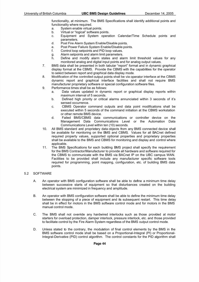
8/3/2019 15901-2008 Bms Ubc Bacnet Bms Master 14dec05 Final
http://slidepdf.com/reader/full/15901-2008-bms-ubc-bacnet-bms-master-14dec05-final 45/95
University of British Columbia UBC BMS Design Guidelines December 14, 2005
Page 44
functionality, at minimum. The BMS Specifications shall identify additional points andfunctionality where required.a. System enable virtual points.b. Virtual or “logical” software points.c. Equipment and System operation Calendar/Time Schedule points and
parameters.d. Post Fire Alarm System Enable/Disable points.e. Post Power Failure System Enable/Disable points.f. Control loop setpoints and PID loop values.g. Alarm setpoints and alarm limit parameters.h. Define and modify alarm states and alarm limit threshold values for any
monitored analog and digital input points and for analog output values.7. BMS data shall be presented in both tabular “report” format and in dynamic graphical
display format at the CBMS. Provide the CBMS with the capabilities for the operator to select between report and graphical data display mode.
8. Modification of the controlled output points shall be via operator interface at the CBMSdynamic report and graphical interface facilities and shall not require BMSmanufacturer proprietary software or special configuration software files.
9. Performance times shall be as follows:a. Data values updated in dynamic report or graphical display reports within
maximum interval of 5 seconds.b. Defined high priority or critical alarms annunciated within 3 seconds of it’s
sensed occurrence.c. CBMS Operator command outputs and data point modifications shall be
executed within 5 seconds of the command initiation at the CBMS workstationor other remote BMS device.
d. Failed BMS/CBMS data communications or controller device on theManagement Data Communications Level or the Automation DataCommunications Level within ten (10) seconds.
10. All BMS standard and proprietary data objects from any BMS connected device shallbe available for monitoring on the BMS and CBMS. Values for all BACnet definedrequired property values, supported optional properties and proprietary propertiesshall be available to the BMS and CBMS for monitoring and display and control whereapplicable.
11. The BMS Specifications for each building BMS project shall specify the requirementfor the BMS Contractor/Manufacturer to provide all hardware and software required for the CBMS to communicate with the BMS via BACnet IP on the UBC campus WAN.Facilities to be provided shall include any manufacturer specific software toolsrequired for programming, point mapping, configuration, etc. of building BMS datapoints.
5.2 SOFTWARE
A. An operator with BMS configuration software shall be able to define a minimum time delaybetween successive starts of equipment so that disturbances created on the buildingelectrical system are minimized in frequency and amplitude.
B. An operator with BMS configuration software shall be able to define the minimum time delaybetween the stopping of a piece of equipment and its subsequent restart. This time delayshall be in effect for motors in the BMS software control mode and for motors in the BMSmanual control mode.
C. The BMS shall not override any hardwired interlocks such as those provided at motor starters for overload protection, damper interlock, pressure interlock, etc. and those providedto facilitate control by the Fire Alarm System regardless of the BMS output control mode.
D. Unless stated to the contrary, the modulation of final control elements by the BMS in theBMS software control mode shall be based on a Proportional-Integral (PI) or Proportional-Integral-Derivative (PID) control algorithm. The control constants for the PID algorithm shall

8/3/2019 15901-2008 Bms Ubc Bacnet Bms Master 14dec05 Final
http://slidepdf.com/reader/full/15901-2008-bms-ubc-bacnet-bms-master-14dec05-final 46/95
University of British Columbia UBC BMS Design Guidelines December 14, 2005
Page 45
be definable by the operator. If self-tuning algorithms are provided, it shall still be possiblefor the operator to manually tune the control loops. The software shall incorporate facilitiesto enable the bumpless transfer of a modulating output from BMS manual control to BMSsoftware control and vice versa and the prevention of integral wind-up. PID algorithms shallmaintain the system operation within the desired tolerance around the setpoint.
E. Provide dynamic graphical trending software at the CBMS that emulates, at minimum, athree point strip chart recorder. This program shall concurrently display three or more plotsof variables in a graphical format. The graphs shall be plotted as the values are sampled in asimilar fashion to a chart recorder and when the plot reaches the right hand side of the X-axis, the X-axis shall scroll to the left so as to accommodate newly sampled data.
F. Provide an energy monitoring software facility in both the CBMS and BMS NDS to monitor and report electrical energy usage and instantaneous energy demand. This feature shallalso store data for recall via the historical data trend package.
G. Provide run time totalizing software facilities at both the CBMS and BMS NDS that willaccumulate the operating times for motors and unitary equipment as selected by the operator using an interactive procedure. Any piece of equipment that has its status monitored by theBMS shall be selectable for inclusion in this feature. It shall be possible to concurrentlymonitor the accumulated operating time for every item of equipment monitored and/or controlled by the BMS. Historical trend data shall be stored in a non-proprietary databasesuch as Microsoft SQL Server in the BMS NDS.
H. Provide demand limiting and duty cycle programs that will duty cycle equipment usage in amanner that conserves energy. The cycling of equipment shall be initiated by one of thefollowing means:
1. Operator defined schedule.2. Peak electric demand control software program.3. Operator manual command.
The proportion of ON time to OFF time in a single cycle shall either be assigned by theoperator using an interactive procedure or the operator may elect to have a variable ON/OFF
ratio based on other criteria.
I. Provide a scheduling program that will enable the BMS to automatically schedule an item of equipment on and off (occupied) and on and off (unoccupied) based on time to allow, for example, the AHU to operate with the outside air dampers closed during non-occupied timeperiods, etc. The operator shall be able to assign a minimum of four start and four stoptimes to each piece of equipment for each day of the week and for holidays. Theseschedules shall only be in effect for a piece of equipment when it is in the BMS softwarecontrol mode. Equipment and space time occupancy time schedules shall be available for display and operator adjustable via the CBMS. The scheduling feature shall conform to theCBMS scheduling interface.
J. Provide equipment fail restart software that will restart equipment shut down as the result of a fire alarm system following the return to normal conditions or a power fail condition.
K. Provide a night setback software program that shall:
1. Start HVAC equipment after normal hours of scheduled operation to maintain buildingafter hour setpoints, while reducing energy consumption.
2. Night setback temperatures for heating shall be initially set at 55 Deg. F. to activatethe heating equipment and 60 Deg. F. to stop the heating equipment. Once activated,the units involved shall operate as specified in the respective sequence of operation.Coordinate the operation of this program with the requirements for terminal unitcontrols.

8/3/2019 15901-2008 Bms Ubc Bacnet Bms Master 14dec05 Final
http://slidepdf.com/reader/full/15901-2008-bms-ubc-bacnet-bms-master-14dec05-final 47/95
University of British Columbia UBC BMS Design Guidelines December 14, 2005
Page 46
L. Provide facilities for alarm notification via both the building BMS NDS and the CBMS via e-mail messaging, wireless text messaging and SNMP.
3. Night setup temperatures for cooling shall be initially set at 90 Deg. F. to activate thecooling equipment and 85 Deg. F. to stop the cooling equipment. Once activated, theunits involved shall operate as specified in the respective sequence of operation.Coordinate the operation of this program with the requirements for terminal unitcontrols.
4. This feature shall be provided for all HVAC equipment under control of the BMS. Theoperator shall be able to enable/disable this function on a unit by unit basis.

8/3/2019 15901-2008 Bms Ubc Bacnet Bms Master 14dec05 Final
http://slidepdf.com/reader/full/15901-2008-bms-ubc-bacnet-bms-master-14dec05-final 48/95
University of British Columbia UBC BMS Design Guidelines December 14, 2005
Page 47
6. CBMS SOFTWARE, DATABASE AND PROGRAMMING REQUIREMENTS
6.1 INTEGRATION OF STANDALONE BUILDING BMS INTO THE CAMPUS BMS
A. The CBMS Contractor shall provide the mapping, storage, and reporting of the building BMSmonitoring and control objects into the CBMS and the preparation of data presentation for the CBMS Management Level Network. The BMS Contractor shall provide to the Owner andto the CBMS Contractor, all necessary documentation, BIBB information, device addressing,etc. as required for the integration of the BMS monitoring and control functions into theCBMS.
B. CBMS installations shall be in compliance with the following requirements and shall providethe following functionality:1. All BMS and CBMS controllers and operator interface workstations shall be devices
that are conformal with the BACnet standardized device types described in Annex L of the ASHRAE Standard 135. BMS devices shall, at minimum, support the BIBB’s(defined in Annex K of ASHRAE Standard 135) and the associated functionality thatare defined as a functional requirement for the device in Annex L of the ASHRAEStandard 135.
2. All BMS controllers, regardless of their device type, shall communicate on the BMS andCBMS networks and shall be “visible” to the CBMS and BMS networks.
3. BMS data shall comply with the BACnet data object property requirements and, atminimum, shall support the properties defined as “required” in ASHRAE Standard 135.
4. All physical BMS monitored input points (binary and analog type) shall be readable andavailable for monitoring at the CBMS and by other BMS controllers.
5. All physical BMS controlled output points (binary and analog type) shall be readableand available for monitoring at the CBMS and by other BMS controllers and shall bewriteable and shall be capable of being controlled/positioned by the CBMS and byother BMS controllers.
6. All software data points and control system parameters critical to the supervisorymonitoring and control of the building systems shall be available for monitoring at theCBMS and by other BMS controllers and/or shall be writeable and shall be capable of being controlled/positioned by the CBMS and by other BMS controllers. Provide thefollowing typical software data points and control parameters with the defined
functionality, at minimum. The BMS Specifications shall identify additional points andfunctionality where required.a. System enable virtual points.b. Virtual or “logical” software points.c. Equipment and System operation Calendar/Time Schedule points and
parameters.d. Post Fire Alarm System Enable/Disable points.e. Post Power Failure System Enable/Disable points.f. Control loop setpoints and PID loop values.g. Alarm setpoints and alarm limit parameters.h. Define and modify alarm states and alarm limit threshold values for any
monitored analog and digital input points and for analog output values.7. BMS data shall be presented in both tabular “report” format and in dynamic graphical
display format at the CBMS. Provide the CBMS with the capabilities for the operator to select between report and graphical data display mode.
8. Modification of the controlled output points shall be via operator interface at the CBMSdynamic report and graphical interface facilities and shall not require BMSmanufacturer proprietary software or special configuration software files.
9. Performance times shall be as follows:a. Data values updated in dynamic report or graphical display reports within
maximum interval of 5 seconds.b. Defined high priority or critical alarms annunciated within 3 seconds of it’s sensed
occurrence.

8/3/2019 15901-2008 Bms Ubc Bacnet Bms Master 14dec05 Final
http://slidepdf.com/reader/full/15901-2008-bms-ubc-bacnet-bms-master-14dec05-final 49/95
University of British Columbia UBC BMS Design Guidelines December 14, 2005
Page 48
c. CBMS Operator command outputs and data point modifications shall be executedwithin 5 seconds of the command initiation at the CBMS workstation or other remote BMS device.
d. Failed BMS/CBMS data communications or controller device on the ManagementData Communications Level or the Automation Data Communications Level withinten (10) seconds.
12. All BMS standard and proprietary data objects from any BMS connected device shallbe available for monitoring on the BMS and CBMS. Values for all BACnet definedrequired property values, supported optional properties and proprietary propertiesshall be available to the BMS and CBMS for monitoring and display and control whereapplicable.
6.2 CBMS DYNAMIC SYSTEM GRAPHIC REQUIREMENTS
A. The work of BMS installation projects in UBC Buildings shall include the integration of thebuilding BMS facilities into the CBMS. The integration of the individual building BMS into thecampus BMS shall include the provision of BMS System Graphics representative of all BMSmonitoring and control facilities/systems. The BMS Designer shall specify detailedrequirements for the BMS Graphic Schematics in the BMS/CBMS Design Documents.
B. The CBMS System Graphics shall be fully dynamic colour graphics. Graphics shall begenerated in a non-proprietary format such as .dwg, JPEG, TIFF, etc. One graphic shall beprovided for each BMS monitored/controlled system. Miscellaneous HVAC and electricalvalues monitored by the BMS shall be displayed in graphic displays of logical groups of equipment.
C. Graphics shall be provided by the CBMS Contractor and fully integrated into the campusBMS. CBMS System Graphics shall be capable of being displayed at any OWSsimultaneously.
D. CBMS System Graphics shall be developed based on UBC standard graphic symbols andcolours. All BMS system graphics shall be coordinated with UBC. The Contractor shallsubmit copies of proposed graphics in the shop drawings for review and approval by theBMS/CBMS Consultant and UBC.
E. CBMS System Graphics shall include the following requirements:
1. All BMS monitored and controlled points shall be displayed on graphics.2. Graphics shall clearly indicate the fail state position for all BMS controlled devices.3. Clearly indicate spring ranges on pneumatic actuated valves and dampers.4. Graphical representation of controlled device position based on spring/control range.5. Monitored value units displayed. For BMS monitored temperature values an icon
indicating temperature units shall be provided.6. Spring ranges displayed for all controlled devices.7. Values/icons for points which are placed in an override state by Operator command
shall be displayed in the colour orange.8. Display System Name and location.
F. Equipment/devices shall be colour coded as follows:
1. Red - Hot Water piping with yellow direction of flow arrows.2. Blue - Chilled Water piping.3. Light Blue - Condenser Water piping.4. Yellow - Steam.5. Brown - Condensate.
G. BMS analog input and analog output point information shall be displayed as follows:
1. Point Name

8/3/2019 15901-2008 Bms Ubc Bacnet Bms Master 14dec05 Final
http://slidepdf.com/reader/full/15901-2008-bms-ubc-bacnet-bms-master-14dec05-final 50/95
University of British Columbia UBC BMS Design Guidelines December 14, 2005
Page 49
2. Expanded Descriptor 3. Automatic Control Priority (Overridden Value, Automatic Control, Disabled, failed, etc.)4. Actual point monitored input / controlled output value.
H. BMS digital input and digital output point information shall be displayed as follows:
1. Point Name.2. Expanded Descriptor.3. Automatic Control Priority (Overridden On/Off, Automatic Control, Disabled, failed,
etc.)4. Point status.
I. Controlled variables shall have the following information displayed:
1. Set point.2. Actual value.3. Alarm limit ranges.4. Facilities shall be provided to override the set point value via a graphical interface in
the associated BMS System Graphic.
J. BMS System Graphics shall be provided as follows:
1. Floor Plans for all building project areas. One graphic per floor level. Floor plans shallindicate the associated AHU service domains. AHU Service domains shall be colour coded.
2. Space temperature, relative humidity, static pressure, air quality sensors, etc. mountedthroughout the project spaces shall be displayed on the floor plan system graphic.
3. Building areas equipped with BMS zone space temperature control facilities shall havea dynamic link to a separate individual graphic for each terminal unit controller.
4. Floor plans shall reflect normal/alarm status for BMS monitored/controlled pointsbased on the following colour codes:
a. Green - Device On and operating under “normal” automatic control priority.b. Yellow - Critical Alarm Condition.
c. Blue - Device Off and operating under “normal” automatic controlpriority.d. Orange - General Alarm Condition.e. Aqua Blue - Point Trouble Condition.f. Red - Immediate Response Alarm Condition.
5. BMS System Graphic shall be provided for each Mechanical and Electrical EquipmentRoom indicating the BMS monitored/controlled equipment locations.
6. BMS System Graphics shall be provided for all BMS monitored/controlled equipmentmounted on building rooftops and exterior building areas.
7. Outside Air Temperature and Relative Humidity shall be displayed on all HVACSystem graphic schematics.
6.3 ALARM MANAGEMENT AND ANNUNCIATION
A. Alarms shall be generated by the BMS and shall be annunciated at the CBMS upon theoccurrence of one of the following events:
1. Failure of a CCP, DCP, UC, or any other BMS hardware components.2. Failure of communications or devices on the Automation Level Network.3. A monitored status indicates a discrepancy between the actual and the required value.4. A monitored value does not meet criteria established by the operator.5. The deviation of a variable from setpoint exceeds operator established criteria.

8/3/2019 15901-2008 Bms Ubc Bacnet Bms Master 14dec05 Final
http://slidepdf.com/reader/full/15901-2008-bms-ubc-bacnet-bms-master-14dec05-final 51/95
University of British Columbia UBC BMS Design Guidelines December 14, 2005
Page 50
a. Sump high level status event
g. XXXX UBC Additional Requirements
6. The output to a final control element is outside operator established criteria.7. A digital input is in the state defined by the operator as indicating an alarm condition.8. Software failures and errors shall be diagnosed and annunciated by the BMS.
Provide configuration of alarming for all monitored and controlled points. BMS Specificationsshall detail all required alarm states, values and limits.
B. BMS alarms shall be assigned priority levels as follows:1. Priority Level 1 – Critical Alarms:
b. Fire Alarm status eventc. AHU low temperature detection device eventd. Main Breaker power fail status evente. Generator fault conditionf. Diesel Tank Storage Tank leak detection event.
2. Priority Level ? - XXXXXX
C. Defined BMS alarm events shall be communicated by the BMS to the CBMS. Definedalarms shall be annunciated at the CBMS workstation. Alarms shall be retained in theCBMS alarm summary.
6.5 TESTING AND COMMISSIONING REQUIREMENTS
A. Integrated BMS/CBMS joint systems tests shall be undertaken to demonstrate that theinteraction between the individual building BMS and the CBMS meets the UBCrequirements. The BMS Subcontractor shall participate in joint verification of the integratedsystems and cooperate with the Owner in the demonstration of the integrated systems.
B. The BMS Specifications shall specify the requirements for the BMS/CBMS integration jointsystems verification in the BMS and CBMS Specifications and/or Contract Documents. TheBMS/CBMS Integrated System Verification shall include the following minimumrequirements:
1. Test all BMS monitored and controlled field devices, BMS data points and all BMSinput and output points. CBMS monitored data point values shall be verified againstactual field device position/state and compared to BMS values to ensure both BMS andCBMS values are the same.
2. CBMS override control of all BMS output points and control data points shall beverified.
3. BMS network and controller device status and data communications status areaccurately monitored at the CMBS. Alarms for failed controllers and failed datacommunications are annunciated.
4. BMS data values displayed on dynamic system graphics or in tabular data format at theCBMS are functional and accurate.
5. CBMS operator control of BMS control output points and control data points isfunctional via the dynamic graphic interface.
6. CBMS facilities for operator adjustment of alarm definition parameters and thresholds,setpoint adjustment, control parameter adjustments, point trend initiation andmodification to trends, etc. are fully functional.
7. The CBMS performance requirements for the monitoring and control of BMS data andfield devices meet the UBC requirements.
8. BMS device addressing and identification definitions are compatible and identical andthe addressing scheme meets with UBC requirements.
9. Point naming used is compatible and conformal with the UBC requirements.
C. Test results shall be documented using test sheets. The test sheets shall be prepared inan appropriate format for the various categories of component and system to be tested.It is the responsibility of the BMS Subcontractor to provide test verification sheets for

8/3/2019 15901-2008 Bms Ubc Bacnet Bms Master 14dec05 Final
http://slidepdf.com/reader/full/15901-2008-bms-ubc-bacnet-bms-master-14dec05-final 52/95
University of British Columbia UBC BMS Design Guidelines December 14, 2005
Page 51
each component and system that accurately reflect the sequences of operation andappropriate data for the components and systems.
D. All test documentation shall be maintained in electronic format and in hard copy.
CBMS/BMS ALARM HANDLING ARCHIVING REQUIREMENTS TO BE COMPLETED.
UBC BMS POINT NAMING CONVENTIONS REQUIREMENTS
UBC BMS CONTROLLER AND DEVICE ADDRESSING AND NAMING CONVENTION REQUIREMENTS

8/3/2019 15901-2008 Bms Ubc Bacnet Bms Master 14dec05 Final
http://slidepdf.com/reader/full/15901-2008-bms-ubc-bacnet-bms-master-14dec05-final 53/95
University of British Columbia UBC BMS Design Guidelines December 14, 2005
Page 52
7. GUIDELINES FOR APPLICATION OF BMS TO TYPICAL HVAC SYSTEMS
7.1 BMS Sequences of Operation, Field Termination Schedules, and System Schematic Diagrams
A. This section of the UBC BMS Design Guidelines identifies BMS monitoring and controlrequirements for typical building HVAC Systems and includes “sequences of operation” for typical building systems. BMS design specifications for all UBC BMS projects shall includeBMS Sequences of Operation detailing the BMS monitoring and automatic control logicprogramming requirements. BMS Sequences of Operation to be provided in BMS DesignSpecifications shall be in the same format as the sequences of operation identified withinthese guidelines.
B. BMS Design Specifications for UBC BMS projects shall detail BMS monitoring and controlrequirements in Field Termination Schedules and System Schematic Diagrams. FieldTermination Schedules and System Schematic Diagrams shall be provided for all BMSmonitored and controlled equipment and systems. The Field Termination Schedules andSystem Schematics shall be provided for each building system and logical group of monitored and controlled equipment. The Field Termination Schedules and SystemSchematics shall clearly identify BMS monitoring and control requirements and shall belabelled and cross reference the associated sequences of operation. Examples of FieldTermination Schedules and System Schematic Diagrams are included in Appendix A1 of these guidelines. Field Termination Schedules and System Schematic Diagrams provided inUBC project BMS Design Specifications shall be based on the same format as indicatedwithin these documents.
C. Sequences of Operation for typical UBC building HVAC systems are identified within thissection. Refer to Appendix A1 of these guidelines for the associated building system FieldTermination Schedule and System Schematic Diagrams.
D. BMS automatic control of building systems and equipment shall not override life safety or equipment protection overrides. The BMS Design Consultant shall specify automatic controlinterface requirements.
7.2 BMS Component and Building Equipment Failure Requirements
A. The BMS Design Specifications shall clearly specify building system/equipment controlrequirements in the event of failure of BMS components and in the event of failure of buildingequipment. The following are general minimum component/equipment failure requirements.
1. DCP/UC Controller Failure
a. associated BMS controlled electric motors/equipment off.b. AHU mixing dampers to full recirculation position.c. steam control valves closed.d. hot water control valves open.e. cooling coil control valves closed.f. fan/pump speeds set to minimum position.g. fan/pump volume flow rate control devices (e.g. inlet vanes, etc.) set to no-load
position.h. isolation dampers closed.i. exhaust dampers and outside air dampers closed.
2. BMS Analog Input Sensor Failure
a. Associated BMS control output retained in last commanded state. If analternative sensor can be utilized for satisfactory control the BMS shallincorporate automatic control logic to implement the revised control.
b. Failure of information only type BMS input points shall be annunciated asalarms.

8/3/2019 15901-2008 Bms Ubc Bacnet Bms Master 14dec05 Final
http://slidepdf.com/reader/full/15901-2008-bms-ubc-bacnet-bms-master-14dec05-final 54/95
University of British Columbia UBC BMS Design Guidelines December 14, 2005
Page 53
3. Controlled Electric Motor/Equipment Failure
a. Anytime the status of BMS controlled equipment is different than the associatedBMS controlled output status the equipment shall be considered as “failed” andshall be shut down by the BMS. The associated BMS controlled system shallalso be shut down. Systems and equipment shut down by the BMS as theresult of failed components shall require a manual Operator command toacknowledge the failed equipment alarm and shall require a manual Operator command to restart the system/equipment. BMS controlled equipment/systemsshut down as the result of a failed component shall not be automaticallyrestarted by the BMS.
b. Where building systems/equipment are shut down by the by the fire alarmsystem in an alarm condition or are shut down as the result of a building power failure, the BMS shall restart the failed equipment/systems in an orderly andpre-defined manner following a manual Operator command. The BMS DesignSpecifications shall specify the post fire alarm equipment restart and the postpower failure equipment restart requirements.
c. All BMS component failures shall be annunciated as an alarm at the definedBMS main central computer facility.
4. If a BMS controlled motor or equipment fails to start as defined in the sequences of operation, the failure shall be annunciated as an alarm and the associated systemshut down.
7.3 BMS Automatic Sequenced Control of AHU Mixing Dampers and Valves
A. Designated air handling units require the BMS to control heating and cooling coil controlvalves and mixing dampers in sequence. BMS facilities shall be provided as follows for air handling units with sequenced control of the heating coil valves, cooling coil valves, and themixing dampers:
1. The mixing dampers (return air, outside air and exhaust air (where applicable)) shall
be modulated in unison to maintain the supply air temperature setpoint. If the supplyair temperature setpoint cannot be maintained then the heating coil control valve or the cooling coil control valve shall be modulated in sequence with the mixing dampersto maintain the supply air temperature setpoint. If heating is required the dampersshall be in the minimum outside air position and the heating coil control valve shall bemodulated to maintain the supply air temperature setpoint. If cooling is required andthe outside air temperature is less than the return air temperature and greater than thesupply air temperature setpoint, the outside air dampers shall be fully open and thechilled water cooling coil valve shall be modulated to maintain the supply air temperature. When the outside air temperature is greater than the supply air temperature setpoint and greater than the return air temperature the mixing damper shall be in the minimum outside air position and the chilled water cooling coil controlvalve shall be modulated to maintain the supply air temperature. When the outside air temperature is less than the supply air temperature setpoint the mixing dampers shallbe modulated to maintain the supply air temperature. The intent is that free coolingshall be provided whenever possible. There shall be no simultaneous heating andcooling. Mixing damper control based on supply air temperature setpoint shall beoverridden when necessary to satisfy minimum outside air requirements.
7.4 General BMS Monitoring and Control Requirements
A. All BMS alarm limit values and setpoints shall be on-line adjustable by a BMS Operator withthe appropriate password access level.

8/3/2019 15901-2008 Bms Ubc Bacnet Bms Master 14dec05 Final
http://slidepdf.com/reader/full/15901-2008-bms-ubc-bacnet-bms-master-14dec05-final 55/95
University of British Columbia UBC BMS Design Guidelines December 14, 2005
Page 54
B. Upon detection of air handling unit shutdown the BMS shall close associated valves and stopassociated pumps.
B. All BMS Operator monitoring and control functions shall be provided with the appropriatepassword access control.
C. A single BMS software control point shall be provided for each BMS controlled system toenable/disable automatic start-up and control of the entire system. BMS controlled systemsshall be capable of being started/stopped either by automatic BMS control or via onlineOperator command.
7.5 Post Fire Alarm Equipment Restart
A. Fire Alarm Systems in buildings will override BMS control of designated equipment in analarm condition. The BMS shall monitor a set of contacts output from the fire alarm systemfor status indication of a building fire alarm. The BMS Controls Contractor shall coordinatebuilding equipment that is shut down by the Fire Alarm System.
D. Alarms shall be annunciated by the BMS to indicate the equipment failure/shut down and thebuilding fire alarm condition. The BMS shall not annunciate nuisance alarms for monitoredinput points on systems shut down by the BMS or fire alarm system (e.g. high supply air temperature, low duct static pressure, etc.).
C. Equipment shut down by the fire alarm system shall not be automatically restarted. TheBMS shall not restart the equipment until the following:
1. Building fire alarm condition has been cleared.2. BMS Operator acknowledges the fire alarm.3. BMS Operator with appropriate access level resets the BMS system shut down
software point.4. BMS Operator with appropriate access level commands a single “Post Fire Alarm
Equipment Restart” software command point.
D. Once the above conditions have been satisfied and the BMS receives a Post Fire Alarm
Equipment restart command the BMS shall initiate the restart of any equipment shut down bythe fire alarm system. The restart sequence shall provide an orderly start-up of the motorsfor each individual system with time delay between restarts of individual systems. Start of systems shall be according to normal system start up sequences. Only those motors whichshould be operational in accordance with the Occupancy Schedule or application softwareprogramming requirements shall be restarted.
7.6 Post Building Power Failure Equipment Restart
A. Power failures in buildings will result in building equipment shutting down. The BMS shallmonitor building electrical distribution equipment status for indication of a building power failure condition. Some building equipment will be serviced with emergency power and UPSpower supplies. The BMS Controls Contractor shall coordinate building equipment that isserviced with emergency and UPS power supplies.
B. Post Building Power Failure Equipment Restart facilities shall be provided to ensure thecontrolled and orderly start up of building equipment following a power failure. The PostBuilding Power Failure Equipment Restart facilities shall be provided based on therequirements identified above for the Post Fire Alarm Equipment Restart.
7.7 Air Handling Unit Optimum Start and Stop Programs
A. Air handling system shall be started by the BMS according to defined Occupancy OperatingSchedules. These schedules exclude the time required for optimum start periods. Heatingshall start in order to provide a minimum space temperature in all rooms of 20 Deg. C. by the

8/3/2019 15901-2008 Bms Ubc Bacnet Bms Master 14dec05 Final
http://slidepdf.com/reader/full/15901-2008-bms-ubc-bacnet-bms-master-14dec05-final 56/95
University of British Columbia UBC BMS Design Guidelines December 14, 2005
Page 55
7.9 Air Handling Unit Supply Air Temperature Reset Schedules
beginning of assigned Occupancy Period with the mixing dampers in the "full recirculation"position. Cooling shall start in order to provide a maximum space temperature in all rooms of 22 Deg. C. by the beginning of the assigned Occupancy Period with the mixing dampers inthe "full recirculation" position. The system shall stop at the end of the assigned OccupancyPeriod and return to the state described in B. above.
7.8 After-hours Equipment Operation
A. Designated air handling systems shall be off during Unoccupied Periods if all spacetemperatures are above 15 Deg. C. If any space temperature falls below 15 Deg. C. thesystem shall be started and operate with the mixing dampers in the full recirculation position,the heating pump on and the heating coil valve fully open to flow through the coil. Thesystem shall return to the off position as described in B. above when all space temperaturesare above 16 Deg. C.
A. The BMS typically controls air handling unit equipment to maintain supply air temperatureconditions from air handling units. Typical UBC building air handling units may be providedwith facilities to automatically reset the supply air temperature setpoint. UBC air handlingunit supply air temperature setpoints are reset based on criteria specific to each application.The BMS designer shall specify setpoint reset facilities to suit the specific application andshall coordinate the reset schedules and setpoint values with UBC, the Architect and theassociated mechanical engineer.
B. The following are a number of BMS air handling unit control applications and associatedsupply air temperature reset schedule schemes that may be applied:
1. Constant Volume Air Handling Unit, No BMS secondary controls, adequate BMSspace temperature sensors.a. BMS to average space temperature values and reset supply air temperature
based on an Average space temperature schedule.
Average Space Temperature Supply Air Temperature Setpoint
20 Deg.C. ?? Deg.C.24 Deg.C. ?? Deg. C.
2. Constant Volume Air Handling Unit, No BMS secondary controls, insufficient spacetemperature monitoring.
a. BMS to reset supply air temperature based on return air temperature resetschedule.
Return Air Temperature Supply Air Temperature Setpoint20 Deg.C. ?? Deg.C.24 Deg.C. ?? Deg. C.
3. Constant or Variable Air Volume Air Handling Unit with BMS secondary controls.
a. BMS to control to design supply air temperature setpoint. BMS to adjust supplyair temperature setpoint to maintain the zone with the greatest demand for cooling as determined by terminal unit damper positions and terminal unitreheat coil control valve positions.
7.10 Dynamic Mixed Air Calculations and Mixing Damper Minimum Outside Air Positioning
A. BMS mixed air calculation facilities shall be provided to dynamically calculate the percentageof outside air flow rate entering air handling units with mixing damper sections (outside air damper, return air damper and exhaust air where applicable). The dynamic mixed air

8/3/2019 15901-2008 Bms Ubc Bacnet Bms Master 14dec05 Final
http://slidepdf.com/reader/full/15901-2008-bms-ubc-bacnet-bms-master-14dec05-final 57/95
University of British Columbia UBC BMS Design Guidelines December 14, 2005
Page 56
calculations shall be based on the relationship between BMS monitored values for outsideair temperature, mixed air temperature, and return air temperature.
B. The BMS shall override normal BMS minimum outside air damper position control tomaintain specified outside air flow requirements based on the dynamic mixed air calculations. The BMS shall implement control strategies to override normal mixing damper control to maintain specified minimum outside air requirements only when the outside air temperature is less than the return air temperature by 10 Deg.C. or more. The BMS shallalso limit mixing damper control to prevent the mixed air temperature from falling below 6Deg.C. Mixing damper settings shall be verified during the Warranty period following aseasonal change.
7.11 Typical Sequence of Operation - Constant Volume Air Handling Unit (AH1)
A. Refer to FTS-0, SD-01.
B. System Off - When the system is off:
1. The return fan shall be off.2. The supply fan shall be off.3. The heating coil pump shall be off if outdoor air temperature is above 15 Deg.C. and
shall remain on whenever the outside air temperature is below 15 Deg.C.4. The mixing dampers shall be in the full recirculation position.5. The cooling coil control valve shall be closed.6. The heating coil control valve shall be closed to flow through the coil.7. The steam humidifier control valve shall be closed.7. System control loops shall be disabled.
C. The Occupancy operating schedule for this system is:
D. System Start-up: On system start-up:
1. Return fan shall be started with the mixing dampers in the full recirculation position.2. Following proof of return fan operation and a time delay, initially set at one (1) minute,
the supply fan shall be started.3. Upon proof of supply fan operation and following a time delay initially set at two (2)minutes the mixing dampers shall be positioned in the minimum outside air positionand the control loops shall be enabled.
E. System Operation:
1. The mixing dampers (outside air damper, return air damper and exhaust air damper) shall bemodulated in unison via single analog output MDC.
2. The mixing dampers shall be modulated in sequence with the heating coil controlvalve and the cooling coil control valve to maintain the supply air temperature setpoint.The supply air temperature setpoint shall be reset according to (BMS DESIGNER TOIDENTIFY RESET REQUIREMENTS).
3. Override control of the mixing damper positions shall be provided based on dynamicmixed air calculations.
4. The heating coil pump shall be started/stopped by the BMS based on the heating coilcontrol valve position. The pump shall be started on a requirement for heat prior to theheating valve be modulated open and shall be stopped when the valve has beenmodulated closed. Minimum run times and minimum off times shall be provided toprevent pump cycling.
5. The BMS shall enable the steam humidifier control on a requirement for humidificationif cooling is not required. The BMS shall open the humidifier two-position steamcontrol valve whenever humidification is required, the associated air handling unitsupply fan is in operation, and the cooling coil control valve is closed. Upon openingthe two-position steam control valve the BMS shall enable automatic modulating

8/3/2019 15901-2008 Bms Ubc Bacnet Bms Master 14dec05 Final
http://slidepdf.com/reader/full/15901-2008-bms-ubc-bacnet-bms-master-14dec05-final 58/95
University of British Columbia UBC BMS Design Guidelines December 14, 2005
Page 57
control of the humidifier steam control valve. The BMS shall modulate the humidifier steam control valves to maintain the zone relative humidity setpoint. The zone relativehumidity shall be the average of the values of the space relative humidity sensors in azone. The zone relative humidity setpoint shall be reset according to the followingoutside air temperature/space relative humidity reset schedule:
Outside Air Temperature Space Relative Humidity Setpoint
-10 Deg. C 35%25 Deg. C 50%
The BMS shall monitor the supply air relative humidity. The BMS shall limit the humidifier steam control valve position to maintain the supply air relative humidity to no greater than80%. An alarm shall be generated and the associated steam control valve shall be closed if the supply air relative humidity remains above 85% for longer than ten minutes.
F. System Shut Down:
1. System shut down shall be initiated by automatically by the BMS according toOccupancy Schedule requirements, by manual Operator command, or via hardwiredinterlocks.
2. On system shut down the BMS shall return the system to the state described for System Off.
3. The BMS shall shut down supply fan, position the mixing dampers to the fullrecirculation position and generate an appropriate alarm message on detection of asupply or mixed air temperature of less than 5 Deg. C. The return fan shall remain on.This BMS software shutdown sequence shall be disabled during the first ten (10)minutes following system start-up.
G. Hardwire Interlocks
1. The low temperature detection device shall be hardwire interlocked to shut down thesupply fan and position the mixing dampers to the full recirculation position whenever a duct air temperature of 5 Deg. C. or lower is sensed. The return fan shall remain in
operation. Device shall be manual reset. The BMS shall monitor the status of the lowtemperature detection device and shall annunciate an alarm in a low temperaturecondition.
2. Provide a hardwired supply air relative humidity high limit controller to override BMScontrol of the humidifier steam valve in a high supply air relative humidity conditioninitially set at 90% RH. The humidification control valve shall be closed until supply air relative humidity has dropped 20% below alarm value. Provide the hardwired supplyair R.H. high limit controller complete with an auxiliary set of dry contacts for alarmmonitoring by the BMS.
7.12 Typical Sequence of Operation - Constant Volume Air Handling Unit - hardwire interlocked RF(AH2)
A. Refer to FTS-02, SD-02.
B. System Off - When the system is off:
1. The return fan shall be off.2. The supply fan shall be off.3. The heating coil pump shall be off if outdoor air temperature is above 15 Deg.C. and
shall remain on whenever the outside air temperature is below 15 Deg.C.4. The mixing dampers shall be in the full recirculation position.5. The cooling coil control valve shall be closed.6. The heating coil control valve shall be closed to flow through the coil.

8/3/2019 15901-2008 Bms Ubc Bacnet Bms Master 14dec05 Final
http://slidepdf.com/reader/full/15901-2008-bms-ubc-bacnet-bms-master-14dec05-final 59/95
University of British Columbia UBC BMS Design Guidelines December 14, 2005
Page 58
7. The steam humidifier control valve shall be closed.7. System control loops shall be disabled.
C. The Occupancy operating schedule for this system is:
D. System Start-up: On system start-up:
1. Supply fan shall be started with the mixing dampers in the full recirculation position.2. The return fan shall be hardwire interlocked to start/stop with the associated air
handling unit supply fan. The return fan shall be on when the supply fan is on andshall be off when the supply fan is off.
3. Upon proof of supply fan operation and following a time delay initially set at two (2)minutes the mixing dampers shall be positioned in the minimum outside air positionand the control loops shall be enabled.
E. System Operation:
1. The mixing dampers (outside air damper, return air damper and exhaust air damper) shall bemodulated in unison via single analog output MDC.
2. The mixing dampers shall be modulated in sequence with the heating coil controlvalve and the cooling coil control valve to maintain the supply air temperature setpoint.The supply air temperature setpoint shall be reset according to (BMS DESIGNER TOIDENTIFY RESET REQUIREMENTS).
3. Override control of the mixing damper positions shall be provided based on dynamicmixed air calculations.
4. The heating coil pump shall be started/stopped by the BMS based on the heating coilcontrol valve position. The pump shall be started on a requirement for heat prior to theheating valve being modulated open and shall be stopped when the valve has beenmodulated closed. Minimum run times and minimum off times shall be provided toprevent pump cycling.
5. The BMS shall enable the steam humidifier control on a requirement for humidificationif cooling is not required. The BMS shall open the humidifier two-position steamcontrol valve whenever humidification is required, the associated air handling unitsupply fan is in operation, and the cooling coil control valve is closed. Upon openingthe two-position steam control valve the BMS shall enable automatic modulating
control of the humidifier steam valve. The BMS shall modulate the humidifier steamcontrol valve to maintain the zone relative humidity setpoint. The zone relativehumidity shall be the average of the values of the space relative humidity sensors in azone. The zone relative humidity setpoint shall be reset according to the followingoutside air temperature/space relative humidity reset schedule:
Outside Air Temperature Space Relative Humidity Setpoint
-10 Deg. C 35%25 Deg. C 50%
The BMS shall monitor the supply air relative humidity. The BMS shall limit thehumidifier steam control valve position to maintain the supply air relative humidity tono greater than 80%. An alarm shall be generated and the associated steam controlvalve shall be closed if the supply air relative humidity remains above 85% for longer than ten minutes.
F. System Shut Down:
1. System shut down shall be initiated by automatically by the BMS according toOccupancy Schedule requirements, by manual Operator command, or via hardwiredinterlocks.
2. On system shut down the BMS shall return the system to the state described for System Off.

8/3/2019 15901-2008 Bms Ubc Bacnet Bms Master 14dec05 Final
http://slidepdf.com/reader/full/15901-2008-bms-ubc-bacnet-bms-master-14dec05-final 60/95
University of British Columbia UBC BMS Design Guidelines December 14, 2005
Page 59
3. The BMS shall shut down supply fan, position the mixing dampers to the fullrecirculation position and generate an appropriate alarm message on detection of asupply or mixed air temperature of less than 5 Deg. C. This BMS software shutdownsequence shall be disabled during the first ten (10) minutes following system start-up.
G. Hardwire Interlocks
1. The low temperature detection device shall be hardwire interlocked to shut down thesupply fan and position the mixing dampers to the full recirculation position whenever a duct air temperature of 5 Deg. C. or lower is sensed. The return fan shall remain inoperation. The BMS shall monitor the status of the low temperature detection deviceand shall annunciate an alarm in a low temperature condition.
2. Provide a hardwired supply air relative humidity high limit controller to override BMScontrol of the humidifier steam valve in a high supply air relative humidity conditioninitially set at 90% RH. The humidification control valve shall be closed until supply air relative humidity has dropped 20% below alarm value. Provide the hardwired supplyair R.H. high limit controller complete with an auxiliary set of dry contacts for alarmmonitoring by the BMS.
7.13 Typical Sequence of Operation - Variable Volume Air Handling Unit (AH3)
A. Refer to FTS-03, SD-03.
B. System Off - When the system is off:
1. The return fan shall be off.2. The supply fan shall be off.3. The heating coil pump shall be off if outdoor air temperature is above 15 Deg.C. and
shall remain on whenever the outside air temperature is below 15 Deg.C.4. The mixing dampers shall be in the full recirculation position.5. The cooling coil control valve shall be closed.6. The heating coil control valve shall be closed to flow through the coil.7. The steam humidifier control valve shall be closed.
8. VSD’s shall be set to the minimum speed.8. System control loops shall be disabled.
C. The Occupancy operating schedule for this system is:
D. System Start-up: On system start-up:
1. Return fan shall be started at minimum speed with the mixing dampers in the fullrecirculation position.
2. Following proof of return fan operation and a time delay, initially set at ten seconds,the supply fan shall be started in minimum speed.
3. Upon proof of supply fan operation, and following a time delay, initially set at tenseconds, the supply and return fan speeds shall be ramped to the 40% air volume
position and the supply and return fan automatic variable speed controls shall beenabled. The fan variable speed drive outputs shall be ramped up over a 300 secondtime period from the minimum 40% air volume position until the ramp output equalsthe associated duct static pressure control loop output at which time the controloutputs shall be released to automatic BMS control.
4. Upon proof of supply fan operation and following a time delay, initially set at two (2)minutes, the mixing dampers shall be positioned in the minimum outside air positionand the control loops shall be enabled.
E. System Operation:

8/3/2019 15901-2008 Bms Ubc Bacnet Bms Master 14dec05 Final
http://slidepdf.com/reader/full/15901-2008-bms-ubc-bacnet-bms-master-14dec05-final 61/95
University of British Columbia UBC BMS Design Guidelines December 14, 2005
Page 60
1. The BMS shall modulate the supply air fan speed to maintain the supply air staticpressure setpoint. Supply air static pressure high limit software facilities shall beprovided to limit the supply fan speed to prevent excessively high supply air staticpressures. The supply air static pressure setpoint shall be Operator adjustable andinitially set at ??? Pa. The return fan speed shall be modulated to maintain anOperator definable percentage difference between the supply and return air volumeflowrates. Initially the return air volume flowrate shall be maintained at 10% less thanthe supply air volume flowrate.
2. The mixing dampers (outside air damper, return air damper and exhaust air damper) shall bemodulated in unison via single analog output MDC.
3. The mixing dampers shall be modulated in sequence with the heating coil controlvalve and the cooling coil control valve to maintain the supply air temperature setpoint.The supply air temperature setpoint shall be reset according to (BMS DESIGNER TOIDENTIFY RESET REQUIREMENTS).
4. Override control of the mixing damper positions shall be provided based on dynamicmixed air calculations.
5. The heating coil pump shall be started/stopped by the BMS based on the heating coilcontrol valve position. The pump shall be started on a requirement for heat prior to theheating valve being modulated open and shall be stopped when the valve has beenmodulated closed. Minimum run times and minimum off times shall be provided toprevent pump cycling.
6. The BMS shall enable the steam humidifier control on a requirement for humidificationif cooling is not required. The BMS shall open the humidifier two-position steamcontrol valve whenever humidification is required, the associated air handling unitsupply fan is in operation, and the cooling coil control valve is closed. Upon openingthe two-position steam control valve the BMS shall enable automatic modulatingcontrol of the humidifier steam control valve. The BMS shall modulate the humidifier steam control valve to maintain the zone relative humidity setpoint. The zone relativehumidity shall be the average of the values of the space relative humidity sensors in azone. The zone relative humidity setpoint shall be reset according to the followingoutside air temperature/space relative humidity reset schedule:
Outside Air Temperature Space Relative Humidity Setpoint
-10 Deg. C 35%25 Deg. C 50%
The BMS shall monitor the supply air relative humidity. The BMS shall limit thehumidifier steam control valve position to maintain the supply air relative humidity tono greater than 80%. An alarm shall be generated and the associated steam controlvalve shall be closed if the supply air relative humidity remains above 85% for longer than ten minutes.
F. System Shut Down:
1. System shut down shall be initiated by automatically by the BMS according toOccupancy Schedule requirements, by manual Operator command, or via hardwiredinterlocks.
2. On system shut down the BMS shall ramp down the supply and return fan speeds andreturn the system to the state described for System Off.
3. The BMS shall shut down supply fan, position the mixing dampers to the fullrecirculation position and generate an appropriate alarm message on detection of asupply or mixed air temperature of less than 5 Deg. C. The return fan shall remain onand shall be set to a operator adjustable speed, initially set at 65 % air volume. ThisBMS software shutdown sequence shall be disabled during the first ten (10) minutesfollowing system start-up.
G. Hardwire Interlocks

8/3/2019 15901-2008 Bms Ubc Bacnet Bms Master 14dec05 Final
http://slidepdf.com/reader/full/15901-2008-bms-ubc-bacnet-bms-master-14dec05-final 62/95
University of British Columbia UBC BMS Design Guidelines December 14, 2005
Page 61
A. Refer to FTS-04, SD-04.
1. The low temperature detection device shall be hardwire interlocked to shut down thesupply fan and position the mixing dampers to the full recirculation position whenever a duct air temperature of 5 Deg. C. or lower is sensed. The return fan shall remain inoperation and shall be set to a operator adjustable speed, initially set at 65 % air volume. Device shall be manual reset. The BMS shall monitor the status of the lowtemperature detection device and shall annunciate an alarm in a low temperaturecondition.
2. Provide a hardwired supply air relative humidity high limit controller to override BMScontrol of the humidifier steam valve in a high supply air relative humidity conditioninitially set at 90% RH. The humidification control valve shall be closed until supply air relative humidity has dropped 20% below alarm value. Provide the hardwired supplyair R.H. high limit controller complete with an auxiliary set of dry contacts for alarmmonitoring by the BMS.
3. Provide duct static pressure high limit devices in the supply and return air ducts to shutdown the associated fans and the air handling unit system in a high duct staticpressure condition. Devices shall be manually reset.
7.14 Typical Sequence of Operation - VAV Outside Air AHU (AH4)
B. System Off - When the system is off:
1. The exhaust fan shall be off.2. The supply fan shall be off.3. The heating coil pump shall be off if outdoor air temperature is above 15 Deg.C. and
shall remain on whenever the outside air temperature is below 15 Deg.C.4. The outside air dampers and the exhaust air dampers shall be fully closed.5. The cooling coil control valve shall be closed.6. The heating coil control valve shall be closed to flow through the coil.7. The steam humidifier control valves shall be closed.8. VSD’s shall be set to the minimum speed.
8. System control loops shall be disabled.
C. The Occupancy operating schedule for this system is:
D. System Start-up: On system start-up:
1. The BMS shall output a start command to the supply fan variable speed drive motor control circuit. The supply fan shall be started in minimum speed. Provide the damper actuator(s) on the outside air dampers hardwire interlocked with the supply fan suchthat the dampers are commanded fully open on a start command and are closed whenthe supply fan is commanded off. Provide damper end switches on the outside air damper sections hardwire interlocked with the supply fan motor control circuit suchthat the supply fan can not operate unless the dampers are in the fully open position.
Provide the end switches hardwire interlocked into both the hand and auto legs of thehand/off/auto motor control circuit to prevent fan operation without the dampers fullyopen.
2. Following proof of supply fan operation and a time delay, initially set at thirty seconds,the BMS shall output a start command to the exhaust fan variable speed drive motor control circuit. The exhaust fan shall be started in minimum speed. Provide thedamper actuator(s) on the exhaust air dampers hardwire interlocked with the exhaustfan such that the dampers are commanded fully open on a start command and areclosed when the exhaust fan is commanded off. Provide damper end switches on theexhaust air damper sections hardwire interlocked with the exhaust fan motor controlcircuit such that the exhaust fan can not operate unless the dampers are in the fullyopen position. Provide the end switches hardwire interlocked into both the hand and

8/3/2019 15901-2008 Bms Ubc Bacnet Bms Master 14dec05 Final
http://slidepdf.com/reader/full/15901-2008-bms-ubc-bacnet-bms-master-14dec05-final 63/95
University of British Columbia UBC BMS Design Guidelines December 14, 2005
Page 62
auto legs of the hand/off/auto motor control circuit to prevent fan operation without thedampers fully open.
3. Upon proof of supply fan operation, and following a time delay initially set at tenseconds, the supply fan speed shall be ramped to the 40% air volume position and thesupply fan automatic variable speed controls shall be enabled. The fan variablespeed drive outputs shall be ramped up over a 300 second time period from theminimum 40% air volume position until the ramp output equals the associated ductstatic pressure control loop output at which time the control output shall be released toautomatic BMS control.
4. Upon proof of exhaust fan operation, and following a time delay initially set at tenseconds, the exhaust fan speed shall be ramped to the 40% air volume position andthe exhaust fan automatic variable speed controls shall be enabled. The fan variablespeed drive outputs shall be ramped up over a 300 second time period from theminimum 40% air volume position until the ramp output equals the associated ductstatic pressure control loop output at which time the control output shall be released toautomatic BMS control.
5. Upon proof of supply and exhaust fan operation the remaining automatic control loopsshall be enabled.
6. On a system start-up if the outside air temperature is less than 6 Deg.C., the BMSshall position the heating coil control valve to the 30 % open position sixty secondsprior to issuing the supply fan start command. Valve control shall be released whenautomatic controls are enabled.
E. System Operation:
1. The BMS shall modulate the supply air fan speed to maintain the supply air staticpressure setpoint. Supply air static pressure high limit software facilities shall beprovided to limit the supply fan speed to prevent excessively high static pressures.The supply air static pressure setpoint shall be Operator adjustable and initially set at??? Pa.
2. The exhaust fan speed shall be modulated to maintain the exhaust air static pressuresetpoint. Exhaust air static pressure low limit software facilities shall be provided tolimit the exhaust fan speed to prevent excessively low static pressures. The exhaustair static pressure setpoint shall be Operator adjustable and initially set at ??? Pa.
3. The heating coil control valve and the cooling coil control valve shall be modulated insequence to maintain the supply air temperature setpoint. The supply air temperaturesetpoint shall be reset according to (BMS DESIGNER TO IDENTIFY RESETREQUIREMENTS).
4. The heating coil pump shall be started/stopped by the BMS based on the heating coilcontrol valve position. The pump shall be started on a requirement for heat prior to theheating valve being modulated open and shall be stopped when the valve has beenmodulated closed. Minimum run times and minimum off times shall be provided toprevent pump cycling.
5. The BMS shall enable the steam humidifier control on a requirement for humidificationif cooling is not required. The BMS shall open the humidifier two-position steamcontrol valve whenever humidification is required, the associated air handling unitsupply fan is in operation, and the cooling coil control valve is closed. Upon openingthe two-position steam control valve the BMS shall enable automatic modulatingcontrol of the humidifier steam control valve. The BMS shall modulate the humidifier steam control valve to maintain the zone relative humidity setpoint. The zone relativehumidity shall be the average of the values of the space relative humidity sensors in azone. The zone relative humidity setpoint shall be reset according to the followingoutside air temperature/space relative humidity reset schedule:
Outside Air Temperature Space Relative Humidity Setpoint
-10 Deg. C 35%25 Deg. C 50%

8/3/2019 15901-2008 Bms Ubc Bacnet Bms Master 14dec05 Final
http://slidepdf.com/reader/full/15901-2008-bms-ubc-bacnet-bms-master-14dec05-final 64/95
University of British Columbia UBC BMS Design Guidelines December 14, 2005
Page 63
The BMS shall monitor the supply air relative humidity. The BMS shall limit thehumidifier steam control valve position to maintain the supply air relative humidity tono greater than 80%. An alarm shall be generated and the associated steam controlvalve shall be closed if the supply air relative humidity remains above 85% for longer than ten minutes.
F. System Shut Down:
1. System shut down shall be initiated automatically by the BMS according to OccupancySchedule requirements, by manual Operator command, or via hardwired interlocks.
2. On system shut down the BMS shall ramp down the supply and exhaust fan speedsand return the system to the state described for System Off.
3. The BMS shall shut down the supply fan and the exhaust fan and generate anappropriate alarm message on detection of a supply air temperature of less than 5Deg. C. This BMS software shutdown sequence shall be disabled during the first ten(10) minutes following system start-up.
G. Hardwire Interlocks
1. The low temperature detection device shall be hardwire interlocked to shut down thesupply fan and close the outside air dampers whenever a duct air temperature of 5Deg. C. or lower is sensed. The BMS shall shut down the exhaust fan and close theexhaust air dampers when a low temperature condition is sensed. Device shall bemanual reset. The BMS shall monitor the status of the low temperature detectiondevice and shall annunciate an alarm in a low temperature condition.
2. Provide a hardwired supply air relative humidity high limit controller to override BMScontrol of the humidifier steam valve in a high supply air relative humidity conditioninitially set at 90% RH. The humidification control valve shall be closed until supply air relative humidity has dropped 20% below alarm value. Provide the hardwired supplyair R.H. high limit controller complete with an auxiliary set of dry contacts for alarmmonitoring by the BMS.
3. Provide static pressure high limit devices in the supply air duct hardwire interlocked to shutdown the associated fan and the air handling unit system in a high static pressure
condition. Provide duct static pressure low limit devices in the exhaust air ducts toshut down the associated fan and the air handling unit system in a low duct staticpressure condition. Devices shall be manually reset.
4. Provide outside air and exhaust air damper actuators hardwire interlocked with theassociated fan motor control circuit as indicated above.
5. Provide damper end switches on the outside air and exhaust air dampers hardwireinterlocked with the associated fan motor control circuit as indicated above.
7.15 Typical Sequence of Operation - Make-up Air AHU (AH5)
A. Refer to FTS-05, SD-05.
B. System Off - When the system is off:
1. The supply fan shall be off.2. The heating coil pump shall be off if outdoor air temperature is above 15 Deg.C. and
shall remain on whenever the outside air temperature is below 15 Deg.C.3. The outside air dampers shall be fully closed.4. The heating coil control valve shall be closed to flow through the coil.5. System control loops shall be disabled.
C. The Occupancy operating schedule for this system is:

8/3/2019 15901-2008 Bms Ubc Bacnet Bms Master 14dec05 Final
http://slidepdf.com/reader/full/15901-2008-bms-ubc-bacnet-bms-master-14dec05-final 65/95
University of British Columbia UBC BMS Design Guidelines December 14, 2005
Page 64
1. The BMS shall output a start command to the supply fan motor control circuit. Providethe damper actuator(s) on the outside air dampers hardwire interlocked with thesupply fan such that the dampers are commanded fully open on a start command andare closed when the supply fan is commanded off. Provide damper end switches onthe outside air damper sections hardwire interlocked with the supply fan motor controlcircuit such that the supply fan can not operate unless the dampers are in the fullyopen position. Provide the end switches hardwire interlocked into both the hand andauto legs of the hand/off/auto motor control circuit to prevent fan operation without thedampers fully open.
D. System Start-up: On system start-up:
2. Upon proof of supply fan operation the automatic controls shall be enabled.3. On a system start-up if the outside air temperature is less than 6 Deg.C., the BMS
shall position the heating coil control valve to the 30 % open position sixty secondsprior to issuing the supply fan start command. Valve control shall be released whenautomatic controls are enabled.
E. System Operation:
1. The heating coil control valve shall be modulated to maintain the supply air temperature setpoint. The supply air temperature setpoint shall be reset according to(BMS DESIGNER TO IDENTIFY RESET REQUIREMENTS).
4. The heating coil pump shall be started/stopped by the BMS based on the heating coilcontrol valve position. The pump shall be started on a requirement for heat prior to theheating valve being modulated open and shall be stopped when the valve has beenmodulated closed. Minimum run times and minimum off times shall be provided toprevent pump cycling.
F. System Shut Down:
1. System shut down shall be initiated automatically by the BMS according to OccupancySchedule requirements, by manual Operator command, or via hardwired interlocks.
2. On system shut down the BMS shall return the system to the state described for
System Off.3. The BMS shall shut down the supply fan and generate an appropriate alarm messageon detection of a supply air temperature of less than 5 Deg. C. This BMS softwareshutdown sequence shall be disabled during the first ten (10) minutes followingsystem start-up.
G. Hardwire Interlocks
1. The low temperature detection device shall be hardwire interlocked to shut down thesupply fan and close the outside air dampers whenever a duct air temperature of 5Deg. C. or lower is sensed. Device shall be manual reset. The BMS shall monitor thestatus of the low temperature detection device and shall annunciate an alarm in a lowtemperature condition.
2. Provide outside air damper actuators hardwire interlocked with the associated fanmotor control circuit as indicated above.
3. Provide damper end switches on the outside air dampers hardwire interlocked with theassociated fan motor control circuit as indicated above.
7.16 Typical Sequence of Operation - Rooftop Self Contained AC Unit (AH6)
A. Refer to FTS-06, SD-06.
B. System Off - When the system is off:

8/3/2019 15901-2008 Bms Ubc Bacnet Bms Master 14dec05 Final
http://slidepdf.com/reader/full/15901-2008-bms-ubc-bacnet-bms-master-14dec05-final 66/95
University of British Columbia UBC BMS Design Guidelines December 14, 2005
Page 65
C. The Occupancy operating schedule for this system is:
1. The fan shall be off and the unit shut down.
D. System Start-up: On system start-up:
1. The BMS shall output a system enable command to the self contained ac unitelectronic controller. Wire to terminations at the electronic controller.
E. System Operation:
1. Once enabled by the BMS the ac unit shall be controlled by the standalone integral acunit controller as provided by the ac unit manufacturer.
2. The BMS shall monitor the status of the ac unit and shall monitor an ac unit commonfault alarm from the ac unit controller. Wire to terminations at the ac unit controller.
F. System Shut Down:
1. System shut down shall be initiated automatically by the BMS according to OccupancySchedule requirements, by manual Operator command, or via hardwired interlocks.
2. On system shut down the BMS shall return the system to the state described for System Off.
3. The BMS shall shut down the supply fan and the exhaust fan and generate anappropriate alarm message on detection of a supply air temperature of less than 5Deg. C. This BMS software shutdown sequence shall be disabled during the first ten(10) minutes following system start-up.
G. Hardwire Interlocks
1. Hardwire interlocks may be required. BMS Designer to coordinate requirements for any hardwire interlocks, BMS wiring terminations and interfaces, etc..
7.17 Chilled Water (CW) and Condenser Water (CSR) Systems
A. Refer to FTS-10, SD-10.
B. System Off - When the system is off:
1. The chilled water pumps shall be off.2. The chillers shall be commanded off.3. The condenser water pumps shall be off.4. The cooling tower fans shall be off.4. All control loops shall be disabled.
C. The Occupancy operating schedule for this system is:
1. This system shall be enabled either by an operator manually entered command at theBMCS or automatically by the BMS based on time schedule or demand by the AHU’s.
2. Provide two BMS operator modes of control, “BMS Manual” and “BMS Automatic”.Selection of operating mode shall be by manual Operator selection. When in the BMSManual mode start up and shut down of the chilled water and condenser water systems shall be by manual Operator BMS command only. When in the BMSAutomatic Mode, start up and shut down of the chilled water and condenser water systems shall be automatically controlled by the BMS as defined in the followingsequences of operation.
3. When in the BMS Automatic mode the chilled water and condenser water system shallbe on whenever there is a demand for cooling by the associated air handling units asdetermined by cooling coils control valve positions. System shall be off if all valves

8/3/2019 15901-2008 Bms Ubc Bacnet Bms Master 14dec05 Final
http://slidepdf.com/reader/full/15901-2008-bms-ubc-bacnet-bms-master-14dec05-final 67/95
University of British Columbia UBC BMS Design Guidelines December 14, 2005
Page 66
are closed and shall be started when any valve is open more than 10%. Provideminimum run time of four (4) hours and minimum off time of two (2) hours. Thesystem shall be on during occupied periods whenever the outside air temperature isabove 20 Deg. C. regardless of cooling coil valve position.
D. System Start-up: On system start-up:
1. BMS shall start the designated "duty" chilled water pump. BMS shall automaticallydesignate "duty" or "standby" status to chilled water pumps based on pump totalizedrun time. Duty pump designation shall be assigned to the pump with the leastaccumulated run time at time of system start-up. If duty pump fails to start or isdisabled the BMS shall start the standby pump.
2. Upon proof of chilled water pump operation the BMS shall start the designated “duty”condenser water pump. BMS shall automatically designate "duty" or "standby" statusto condenser water pumps based on pump totalized run time. Duty pump designationshall be assigned to the pump with the least accumulated run time at time of systemstart-up. If duty pump fails to start or is disabled the BMS shall start the standbypump.
3. Following proof of chilled water and condenser water pumps, and following anOperator adjustable time delay initially set at thirty seconds, if there is not a condenser water low level alarm the BMS shall output an enable command to the chiller controlpanel provided by the chiller manufacturer. Once enabled by the BMS, control of thechiller shall be by the chiller control panel. The BMS chiller enable/disable controlsoftware shall incorporate minimum chiller run times and minimum times betweenchiller restarts
4. BMS Controls Contractor shall furnish flow switches for installation by the MechanicalContractor in the chilled water supply and return as well as the condenser water supply and return lines and shall hardwire interlock these devices to the chiller controlpanel to prevent chiller operation without flow detected. Flow switches shall behardwire interlocked into the hand and auto branches of the hand/off/auto controlcircuit for the chiller.
5. BMS shall monitor chiller status and chiller fault alarms from the integral chiller controlpanel. Coordinate wiring terminations with the chiller manufacturer. Provide all wiringand auxiliary relays required to monitor multiple chiller fault alarms as a common pointon the BMS.
6. Upon proof of condenser water pump operation the BMS shall enable the condenser water system controls. Upon proof of condenser water pump operation the BMS shallcontrol the cooling tower fans to maintain the condenser water supply temperature.
E. System Operation:
1. The BMS shall output a modulating control output to the chiller control panel for chilledwater supply temperature setpoint reset control. Provide the chilled water supplytemperature setpoint reset signal time averaged to adjust the chilled water supplytemperature setpoint over a span of 6 Deg. C. The chilled water supply temperaturesetpoint shall be adjusted based on air handling unit chilled water control valvepositions. Coordinate chilled water supply temperature setpoint reset signalrequirements with Chiller Manufacturer.
2. (CENTRIFUGAL CHILLER ONLY) The BMS shall output a chiller current demandsignal to the chiller control panel to limit the maximum operating capacity of the chiller based on electrical current demand. The current limiting value shall Operator adjustable and shall be manually set.

8/3/2019 15901-2008 Bms Ubc Bacnet Bms Master 14dec05 Final
http://slidepdf.com/reader/full/15901-2008-bms-ubc-bacnet-bms-master-14dec05-final 68/95
University of British Columbia UBC BMS Design Guidelines December 14, 2005
Page 67
3. (If Cooling Tower is Equipped with a By-pass) If the outside air temperature is belowan operator defined setpoint, the cooling tower bypass valve shall be positioned tobypass flow to the tower sumps.
4. If the outside air temperature is below an operator defined setpoint, the cell isolationvalves for all cells shall open and allow flow over the tower without the fan operating.If the condenser water supply temperature setpoint can not be maintained for anOperator adjustable period of time, initially set at two minutes, then the isolation valveson the operator selected lead tower shall remain open and all other cell isolationvalves shall close. The lead fan shall start on low speed. The speed of the operatingfan within the cell shall be controlled to maintain the condenser water supplytemperature setpoint.
5. If the lead tower cell is operating at low speed and the condenser water supplytemperature setpoint can not be maintained for an operator defined period, then thefollowing staging shall occur, with appropriate time delays to prevent excessive fanstarting/stopping:
a. Stage 2 - First cell high speed.b. Stage 3 - Second cell low speed.c. Stage 4 - Second cell high speed.d. Stage 5 - Third cell low speed.e. Stage 6 - Third cell high speed.f. etc. as determined by the # of cooling tower cells.
The above sequence shall reverse as required to maintain the condenser water supplytemperature setpoint. Provide satisfactory time delays between switching fans to lowspeed from high speed operation. Coordinate cooling tower control requirements withthe cooling tower manufacturer.
6. Provide condenser water supply temperature setpoint reset based on wet bulbtemperature approach. Coordinate reset schedule and minimum allowable condenser water temperature with the chiller and cooling tower manufacturers/suppliers.
F. System Shut Down:
1. System shut down shall be initiated automatically by the BMS according to OccupancySchedule requirements and/or air handling unit cooling requirements, by manualOperator command, or via hardwired interlocks.
2. The condenser water system shall be shut down by the BMS if none of the chillingunits are operating.
3. On system shut down the BMS shall return the system to the state described for System Off.
G. Hardwire Interlocks
1. Provide flow switches installed in the chilled water supply and return and thecondenser water supply and return lines hardwire interlocked with the chiller controlpanel as identified above.
2. Additional hardwire interlocks may be required associated with the chiller and coolingtowers. Provide all required hardwire interlock facilities as identified elsewhere in theDivision 15 and Division 16 Specifications.
H. Alarm setpoints - The BMCS shall generate an alarm:
1. If the chilled water supply temperature is outside the operator established low andhigh alarm limits, which shall be initially set at 38 Deg. F. and 42 Deg. F.
2. If a pump or chiller fails to start or fails in service.

8/3/2019 15901-2008 Bms Ubc Bacnet Bms Master 14dec05 Final
http://slidepdf.com/reader/full/15901-2008-bms-ubc-bacnet-bms-master-14dec05-final 69/95
University of British Columbia UBC BMS Design Guidelines December 14, 2005
Page 68
3. If the condenser water supply temperature is outside the operator established low andhigh alarm limits, which shall be initially set at 4 Deg. F. around the current setpoint.
I. Setpoints - The setpoints for the system shall be determined as follows:
1. The condenser water supply temperature setpoint shall be set initially at 85 Deg. F.during normal operation and 40 Def. F. during economizer operation.

8/3/2019 15901-2008 Bms Ubc Bacnet Bms Master 14dec05 Final
http://slidepdf.com/reader/full/15901-2008-bms-ubc-bacnet-bms-master-14dec05-final 70/95
University of British Columbia UBC BMS Design Guidelines December 14, 2005
Page 69
1. The outside air temperature low limit for bypass control shall be 36 Deg. F.1. The condenser water supply temperature setpoint during after hours operation shall
be 85 Deg. F.2. The time delay for cell staging shall be 10 minutes.3. The switch over setpoint for staging fans off shall be 5 Deg. F. below setpoint.4. The plant condenser water supply temperature setpoint shall be 65 Deg. F.
7.18 Supply Hot Water System (SHW)
A. Refer to FTS-15, SD-15.
B. System Off - When the system is off:
1. Hot water circulation pumps shall be off.2. Steam control valves shall be closed.3. Three way mixing valve on the secondary hot water system shall be fully closed to
flow through from the hot water supply.4. Control loops shall be disabled.
C. The Occupancy operating schedule for this system is:
1. System shall be started/stopped by the BMS according to the Occupancy Scheduleand after hours space temperature control requirements.
2. Additionally the system shall be on if any air handling unit supply fans or Domestic HotWater pumps are in operation or as required for after hours low space temperaturecontrol requirements.
3. This system shall be off if all air handling units and pumps are off and the outside air temperature is greater than 21 Deg. C.
D. System Start-up: On system start-up:
1. BMS shall start the designated "duty" hot water supply pump. BMS shall automaticallydesignate "duty" or "standby" status to the hot water pumps based on pump totalizedrun time. Duty pump designation shall be assigned to the pump with the least
accumulated run time at time of system start-up. If duty pump fails to start or isdisabled the BMS shall start the standby pump.2. Upon proof of hot water supply pump operation and following an Operator adjustable
time delay, initially set at one (1) minute, the control loops shall be enabled.3. Provide pump minimum run and off times. Pump minimum run time and minimum off
time shall be Operator adjustable and initially set at thirty (30) minutes.
E. System Operation:
1. The BMS shall modulate the 1/3 - 2/3 steam control valves in sequence to maintainthe hot water supply temperature setpoint. The steam control valves shall besequenced such that the 1/3 capacity valve is modulated fully open first. The 2/3capacity valve shall be modulated open once the 1/3 valve is fully open and the hotwater supply temperature setpoint has not been achieved. The hot water supplytemperature setpoint shall be Operator adjustable and shall initially be set at 93 Deg.C.
2. The BMS shall modulate the secondary radiation water three-way mixing valve tomaintain the radiation/reheat hot water supply temperature setpoint. Theradiation/reheat hot water supply temperature setpoint shall be reset based on anoutside air temperature reset schedule as follow:
HOT WATER SUPPLYOUTSIDE AIR TEMPERATURE TEMPERATURE SETPOINT

8/3/2019 15901-2008 Bms Ubc Bacnet Bms Master 14dec05 Final
http://slidepdf.com/reader/full/15901-2008-bms-ubc-bacnet-bms-master-14dec05-final 71/95
University of British Columbia UBC BMS Design Guidelines December 14, 2005
Page 70
Provide BMS software point for hot water supply temperature setpoint adjustment.Provide facilities to enabled the Operator to adjust the hot water supply temperaturesetpoint by +/- 10 C. If the hot water supply temperature is 98 Deg.C. or above, thesteam valves shall be closed and an alarm generated.
-10 Deg. C. 93 Deg. C.15 Deg. C. 60 Deg. C.
F. System Shut Down:
1. System shut down shall be initiated automatically by the BMS according to OccupancySchedule requirements and/or air handling, space and domestic hot water heatingrequirements, by manual Operator command, or via hardwired interlocks.
2. On system shut down the BMS shall return the system to the state described for System Off.
G. Hardwire Interlocks
1. None identified with this system.
7.19 Domestic Hot Water System
A. Refer to FTS-16, SD-16.
B. System Off - When the system is off:
1. The domestic hot water circulation pump shall be off.2. Control loops shall be disabled.
C. The Occupancy operating schedule for this system is:
1. The system shall be enabled at an Operator adjustable period of time before the startof the Occupancy Period, initially set at 30 minutes, and shall be disabled at the end of the Occupancy Period.
D. System Start-up: On system start-up:
1. BMS shall start/stop the domestic hot water recirculation pump to maintain thedomestic hot water return temperature at setpoint.
E. System Operation:
1. Control of the domestic hot water heater shall be via standalone controls. Thedomestic hot water temperature controls shall remain operational continuously 24hours per day.
2. Once enabled to operate by the BMS, the domestic hot water circulation pump shallbe cycled on/off to maintain the domestic hot water return temperature at setpoint.The pump shall be started when the domestic hot water return temperature is belowsetpoint and shall be stopped when below setpoint. Provide deadbands betweenpump on/off commands. Provide Operator adjustable minimum run and off timesinitially set at five minutes.
F. System Shut Down:
1. System shut down shall be initiated automatically by the BMS according to OccupancySchedule requirements, by manual Operator command, or via hardwired interlocks.
2. On system shut down the BMS shall return the system to the state described for System Off.

8/3/2019 15901-2008 Bms Ubc Bacnet Bms Master 14dec05 Final
http://slidepdf.com/reader/full/15901-2008-bms-ubc-bacnet-bms-master-14dec05-final 72/95
University of British Columbia UBC BMS Design Guidelines December 14, 2005
Page 71
G. Hardwire Interlocks
1. There are no hardwire interlock requirements associated with this system.
END OF DESIGN GUIDELINES

8/3/2019 15901-2008 Bms Ubc Bacnet Bms Master 14dec05 Final
http://slidepdf.com/reader/full/15901-2008-bms-ubc-bacnet-bms-master-14dec05-final 73/95
UBC BMS Design Guidelines BMS FIELD TERMINATION SCHEDULES HMA Consulting, Inc. Appendix A1
Page: 1
December 14, 2005
SCHEDULES AND SYSTEM SCHEMATICS
1. FIELD TERMINATION SCHEDULES AND SYSTEM SCHEMATICS
1.1 BMS Monitoring and Control - Typical HVAC Systems
A. Appendix A1 of the UBC Design Guidelines includes Field Termination Schedules andSystem Schematic Diagrams for Typical HVAC Systems. The BMS Design Consultantshall apply BMS monitoring and control to UBC HVAC systems using these asguidelines. There will be numerous criteria which will influence the BMS application toeach specific building HVAC system including building age, project budgets, systemcomplexity, interaction with other building systems, building use, etc. This section of theUBC Design Guidelines details the points required to undertake the monitoring andcontrol functions of the BMS. The BMS monitoring and control facilities identified areminimum requirements and additional facilities shall be added if needed to for BMSmonitoring and control.
B. The following abbreviations are based on the UBC approved standards for buildingsystems as indicated in the UBC Mechanical Systems Guide Specifications and havebeen used in the BMS Sequences of Operation, Field Termination Schedules and theSystem Schematic Sheets:
1. OA - Outdoor Air 2. EA - Exhaust Air 3. SA - Supply Air 4. RA - Return Air 5. MA - Mixed Air 6. CSRS - Condenser Water Supply
7. CSRR - Condenser Water Return8. CWS - Chilled Water Supply9. CWR - Chilled Water Return10. DHW - Domestic Hot Water 11. DHWS - Domestic Hot Water Supply12. DHWR - Domestic Hot Water Return13. HWS - Hot Water Supply14. HWR - Hot Water Return15. NO - Normally Open16. NC - Normally Closed17. STM - Steam18. CND - Condensate
1.2 Field Termination Schedules - General
A. The Field Termination Schedules (FTS) identify BMS monitoring and controlrequirements to be provided for the associated building systems. Where BMS monitoringand control requirements are identified in the FTS’s and System Schematic Diagram’sthe BMS Contractor shall provide the device and monitor and/or control the device by theBMS.
B. The BMS shall not override any hardwired interlocks including safety interlocks. BMScontrol of motors shall only be possible when the HOA selector switch is in the Autoposition.
C. Unless the BMS Specifications and Contract Documents specifically indicate thatcomponents are to be furnished by others the BMS Contractor shall provide (furnish and

8/3/2019 15901-2008 Bms Ubc Bacnet Bms Master 14dec05 Final
http://slidepdf.com/reader/full/15901-2008-bms-ubc-bacnet-bms-master-14dec05-final 74/95
UBC BMS Design Guidelines BMS FIELD TERMINATION SCHEDULES HMA Consulting, Inc. Appendix A1
Page: 2
December 14, 2005
install) all of the components necessary to meet the monitoring or control requirementsand shall provide cabling, conduit and all other components and work required to connectthe point to the PIM at the DCP or ASC and to have the point fully functional on the BMS.The BMS Design Consultant shall fully coordinate all components and facilities to beprovided by others with the Owner, Architect, building design team, etc. as required.
A. The schematic diagrams indicate the general configuration of the building systems andthe associated BMS monitoring and control requirements. Locations of sensors anddevices shall be provided approximately as indicated. All final mounting and sensinglocations shall be specifically designed for each application and shall be fully coordinatedby the BMS Contractor with the Owner, Architect, BMS Consultant and other Trades.
B. The System Schematic Diagrams are identified on the associated FTS or on the pageimmediately following the associated FTS. The Field Termination codes identified on theschematic diagrams cross reference the associated FTS.
1.3 System Schematic Diagrams
2. DEFINITION OF THE FIELD TERMINATION SCHEDULES
2.1 BMS Field Termination Schedules
A. The Field Termination Schedules define the minimum monitoring and control functions tobe undertaken by the BMS.
B. The column headed FT contains the tag that enables cross reference between the FieldTermination Sheets and the System Diagrams
C. The column headed DESCRIPTION provides an English language description of thepoint to be monitored or controlled.
D. The column headed DI indicates the digital input monitoring requirements. The digitalinput codes are as follows:
1. Current sensing transformer and relay for motor status.2. No volt (dry) contacts at equipment or instrumentation on equipment as provided
by others.3. Monitor motor status via contacts provided by others at VSD or motor interface
terminal strip.4. Monitor VSD device common alarm via contacts provided by others at the VSD
controller.5. Air differential pressure switch (Filter Status Indication).6. Low Temperature Detection Device (Air Plenum Service).7. Low Temperature Detection Device (Water Service - thermowell installation).8. Level Switch.9. Damper end switch.10. Negative Pressure (Vacuum) Switch (Air Service). Range suitable for
application.11. Pulsed input signal from water meter provided by others. Coordinate pulse
signal requirements.12. Pulsed input signal provided by Division 16. Coordinate pulse signal
requirements.13. Air differential pressure switch (duct static pressure limit switch).14. Door position switch for BMS status monitoring of field panel door position.15. Provide and monitor 2 pressure switches sensing the pneumatic controls air main
supply for BMS monitoring of high and low pressure alarm conditions. Monitor the two devices as a single point on the BMS.

8/3/2019 15901-2008 Bms Ubc Bacnet Bms Master 14dec05 Final
http://slidepdf.com/reader/full/15901-2008-bms-ubc-bacnet-bms-master-14dec05-final 75/95
UBC BMS Design Guidelines BMS FIELD TERMINATION SCHEDULES HMA Consulting, Inc. Appendix A1
Page: 3
December 14, 2005
E. The column headed DO indicate the digital output control requirements. The digitaloutput codes are as follows:
2. Provide two position damper control.
6. Provide on and off control of lighting relays provided by Division 16. Providegrouping of zones as indicated in the Division 16 Drawings. Refer to Division 16Drawings for locations of each lighting relay panel.
F. The column headed AI indicates the analog input monitoring requirements. The analoginput codes are as follows:
16. Pressure Switch (Water Service) installed in domestic cold water supply pipingfor low pressure alarm indication to BMS.
1. Provide and control a relay across the appropriate terminals at the MCC motor control circuit wiring terminal strip or VSD controller, as applicable, for thestop/start control of a motor.
3. Provide two position valve control.4. Provide BMS control output to Cooling Tower Fan control circuit terminal strip
provided by others for BMS control of cooling tower fan motor.5. Provide BMS control output to terminal strip at chiller control panel for BMS
enable/disable control of chiller machine.
7. Provide BMS control output to terminal strip at rooftop air handling unit for BMSenable/disable control.
1. Provide and monitor a duct mounted single point temperature sensor - 0 Deg.C.to 50 Deg.C. range.
2. Provide and monitor a duct mounted averaging temperature sensor - 0 Deg.C. to50 Deg.C. range.
3. Provide and monitor a thermowell mounted temperature sensor - 0 Deg.C. to 100Deg. C range.
4. Provide and monitor an outside air temperature sensor - (-) 20 Deg.C. to 40
Deg.C. range.5. Provide and monitor a wall mounted space temperature sensor - 0 Deg.C to 50Deg.C. range.
6. Provide and monitor a wall mounted button type space temperature sensor- 0Deg.C to 50 Deg.C. range.
7. Provide and monitor a water differential pressure sensor.8. Provide and monitor a duct static pressure sensor.9. Provide and monitor a space static pressure sensor.10. Provide and monitor an outside air relative humidity sensor.11. Provide and monitor a duct mounted relative humidity sensor.12. Provide and monitor fan inlet air flow rate sensor.13 . Monitor instrumentation on the water chilling unit control panel.14. Provide and monitor steam pressure sensor and transmitter.15. Provide and an outside air dewpoint temperature sensor and transmitter.16. Provide and monitor a Carbon Dioxide (CO 2) sensor and transmitter.17. Provide and monitor an insertion turbine water flowmeter.18 . Provide and monitor an ambient light level sensor.19. Provide and monitor a domestic water pressure sensor and transmitter.20. Monitor 4-20 mA or 0 - 10 vdc signal provided by others.21. Provide and monitor an air flow rate station and differential pressure transmitter.22. Provide and monitor a wall mounted space relative humidity sensor and
transmitter.23. Provide and monitor a thermowell mounted temperature sensor - 0 Deg.C. to 50
Deg.C. range.

8/3/2019 15901-2008 Bms Ubc Bacnet Bms Master 14dec05 Final
http://slidepdf.com/reader/full/15901-2008-bms-ubc-bacnet-bms-master-14dec05-final 76/95
UBC BMS Design Guidelines BMS FIELD TERMINATION SCHEDULES HMA Consulting, Inc. Appendix A1
Page: 4
December 14, 2005
5. Provide modulating BMS control output for chiller kVA demand limiting signal tochiller control panel.
2. Provide and interlock an air differential pressure switch to shut down theassociated fan in the event of high duct static pressure condition.
4. Provide damper end switch hardwire interlocked with the associated motor starter/VSD terminal strip to prevent the fan(s) from operating until the damper(s)are completely open. Provide end switches as required.
G. The column headed AO indicates the analog output monitoring requirements. The BMSContractor shall coordinate the signal ranges with the controlled device. The analogoutput codes are as follows:
1. Provide modulating BMS control output to valve actuator.2. Provide modulating BMS control output to damper actuator.3. Provide modulating BMS control output to electric motor VSD for speed control.4. Provide modulating BMS control output for chilled water temperature set point
reset signal to chiller control panel.
H. The column headed HI indicates the hardwired interface requirement. These devices arenot monitored by the BMS unless indicated in any of the previous columns. Thehardwired interlock codes are as follows:
1. Provide and interlock a water differential pressure switch to prove flow throughthe chiller bundle to prevent the water chilling unit from operating unless water
flow is proven. Provide flow switch in both the condenser water and chilled water lines.
3. Provide return fan hardwire interlocked to start/stop with the supply fan motor.Provide the hardwire interlock wired into the auto leg of the return fanhand/off/auto motor control circuit.
5. Provide low temperature detection device hardwire interlocked with the supplyfan motor control circuit to shut down fan in a low temperature condition. Providesafety device hardwire interlocked into the hand/off/auto motor control circuit to
prevent fan operation in either hand or auto position in a low temperaturecondition.6. Provide and interlock an air differential pressure switch to shut down the
associated fan in the event of low duct static pressure condition.
I. The column headed CI indicates the digital communications interface requirements tometers or controllers provided by others. The communications interface codes are asfollows:
1. (Not presently Used)

8/3/2019 15901-2008 Bms Ubc Bacnet Bms Master 14dec05 Final
http://slidepdf.com/reader/full/15901-2008-bms-ubc-bacnet-bms-master-14dec05-final 77/95
UBC BMS Design Guidelines BMS FIELD TERMINATION SCHEDULES HMA Consulting, Inc. Appendix A1
Page: 5
December 14, 2005
1. Monitor negative static pressure in exhaust air duct. Coordinate signal range.2. BMS automatically calculated point. Provide BMS monitoring of the low and high
range steam flow rate meters, the steam temperature and the steam gaugepressure as provided by others. The BMS shall automatically identify the meter recording steam flow within its operating range. The BMS shall utilize the signalfrom the selected meter to calculate steam flow rate and steam energyconsumption. The BMS shall monitor/display the steam flow rate and steamenergy consumption. The BMS shall utilize the steam temperature and steampressure values and steam table data within the BMS to calculate the steamenergy values. The BMS shall totalize the steam flow and steam energyconsumption and shall upload the totalized values to the BMS main computer.
J. The column headed NOTES indicates additional information either by description or code. The NOTE codes are:
3. Monitor multiple generator fault alarms as a single alarm on the BMS. Wire toterminals provided by others.

8/3/2019 15901-2008 Bms Ubc Bacnet Bms Master 14dec05 Final
http://slidepdf.com/reader/full/15901-2008-bms-ubc-bacnet-bms-master-14dec05-final 78/95
UBC BMS Design Guidelines BMS FIELD TERMINATION SCHEDULES HMA Consulting, Inc. Appendix A1
Page: 6
December 14, 2005
FIELD TERMINATION SCHEDULE : 01SYSTEMS : TYPICAL CONSTANT VOLUME AHU (AH1)
FT DESCRIPTION DI DO AI AO HI CI NOTES
SFC SUPPLY FAN CONTROL 1
SFS SUPPLY FAN STATUS 1
RFC RETURN FAN CONTROL 1
RFS RETURN FAN STATUS 1
HPC PUMP CONTROL 1
HPS PUMP STATUS 1
DC DAMPER CONTROL 2
HCC HEATING COIL VALVECONTROL
1
CCC COOLING COIL VALVECONTROL
1
HVC HUMIDIFIER STEAM VALVECONTROL
1
HSJ HUMIDIFIER STEAM JACKETVALVE CONTROL
3
SAT SUPPLY AIR TEMPERATURE 1
RAT RETURN AIR TEMPERATURE 1
MAT MIXED AIR TEMPERATURE 2
SARH SUPPLY AIR RELATIVE
HUMIDITY
11
RARH RETURN AIR RELATIVEHUMIDITY
11
ST(X) SPACE TEMPERATURE 5 Typical of (x)
SRH(X) SPACE RELATIVE HUMIDITY 22 Typical of (x)
FS FILTER STATUS 5
LT LOW TEMPERATUREDETECTION DEVICE
6 5

8/3/2019 15901-2008 Bms Ubc Bacnet Bms Master 14dec05 Final
http://slidepdf.com/reader/full/15901-2008-bms-ubc-bacnet-bms-master-14dec05-final 79/95
UBC BMS Design Guidelines BMS FIELD TERMINATION SCHEDULES HMA Consulting, Inc. Appendix A1
Page: 7
December 14, 2005
SCHEMATIC DIAGRAM : 01SYSTEMS : TYPICAL CONSTANT VOLUME AHU (AH1)
SFHC CC
AB
ABHWS
HWR
CWSCWR
LPS
SAT
RAT
ST(X)MAT SARH
RARH
SRH(X)
LTFSDC
RFSRFC
SFSSFC
HCC CCC
HVC
HSJ
HPCHPS

8/3/2019 15901-2008 Bms Ubc Bacnet Bms Master 14dec05 Final
http://slidepdf.com/reader/full/15901-2008-bms-ubc-bacnet-bms-master-14dec05-final 80/95
UBC BMS Design Guidelines BMS FIELD TERMINATION SCHEDULES HMA Consulting, Inc. Appendix A1
Page: 8
December 14, 2005
FIELD TERMINATION SCHEDULE : 02SYSTEMS : TYPICAL CONSTANT VOLUME AHU (AH2)
FT DESCRIPTION DI DO AI AO HI CI NOTES
SFC SUPPLY FAN CONTROL 1
SFS SUPPLY FAN STATUS 1
RFI RETURN FAN INTERLOCK 3
RFS RETURN FAN STATUS 1
HPC PUMP CONTROL 1
HPS PUMP STATUS 1
DC DAMPER CONTROL 2
HCC HEATING COIL VALVECONTROL
1
CCC COOLING COIL VALVECONTROL
1
HVC HUMIDIFIER STEAM VALVECONTROL
1
HSJ HUMIDIFIER STEAM JACKETVALVE CONTROL
3
SAT SUPPLY AIR TEMPERATURE 1
RAT RETURN AIR TEMPERATURE 1
MAT MIXED AIR TEMPERATURE 2
SARH SUPPLY AIR RELATIVE
HUMIDITY
11
RARH RETURN AIR RELATIVEHUMIDITY
11
ST(X) SPACE TEMPERATURE 5 Typical of (x)
SRH(X) SPACE RELATIVE HUMIDITY 22 Typical of (x)
FS FILTER STATUS 5
LT LOW TEMPERATUREDETECTION DEVICE
6 5

8/3/2019 15901-2008 Bms Ubc Bacnet Bms Master 14dec05 Final
http://slidepdf.com/reader/full/15901-2008-bms-ubc-bacnet-bms-master-14dec05-final 81/95
UBC BMS Design Guidelines BMS FIELD TERMINATION SCHEDULES HMA Consulting, Inc. Appendix A1
Page: 9
December 14, 2005
SYSTEMS : TYPICAL CONSTANT VOLUME AHU (AH2) SCHEMATIC DIAGRAM : 02
SF
HC CC
AB
ABHWS
HWR
CWSCWR
LPS
SAT
RAT
ST(X)MAT SARH
RARH
SRH(X)
LTFSDC
RFS
SFS
SFC
HCC CCC
HVC
HSJ
HPCHPS
RFI
FIELD TERMINATION SCHEDULE : 03

8/3/2019 15901-2008 Bms Ubc Bacnet Bms Master 14dec05 Final
http://slidepdf.com/reader/full/15901-2008-bms-ubc-bacnet-bms-master-14dec05-final 82/95
UBC BMS Design Guidelines BMS FIELD TERMINATION SCHEDULES HMA Consulting, Inc. Appendix A1
Page: 10
December 14, 2005
SYSTEMS : VAV AHU - AH3
FT DESCRIPTION DI DO AI AO HI CI NOTES
SFC SUPPLY FAN CONTROL 1
SFS SUPPLY FAN STATUS 1
SFSC SUPPLY FAN SPEEDCONTROL
3
SFSA SUPPLY FAN SPEED DRIVEFAULT ALARM
4
RFC RETURN FAN CONTROL 1
RFS RETURN FAN STATUS 1
RFSC RETURN FAN SPEEDCONTROL
3
RFSA RETURN FAN SPEED DRIVEFAULT ALARM
4
HPC PUMP CONTROL 1
HPS PUMP STATUS 1
DC DAMPER CONTROL 2
HCC HEATING COIL VALVECONTROL
1
CCC COOLING COIL VALVECONTROL
1
HVC HUMIDIFIER STEAM VALVECONTROL
1
HSJ HUMIDIFIER STEAM JACKETVALVE CONTROL
3
SAT SUPPLY AIR TEMPERATURE 1
RAT RETURN AIR TEMPERATURE 1
MAT MIXED AIR TEMPERATURE 2
SARH SUPPLY AIR RELATIVEHUMIDITY
11
SASP SUPPLY AIR STATICPRESSURE
8 MOUNT DEVICE ATLOCATION 2/3 DOWNLONGEST DUCT RUN
RARH RETURN AIR RELATIVEHUMIDITY
11
ST(X) SPACE TEMPERATURE 5 Typical of (x)
SRH(X) SPACE RELATIVE HUMIDITY 22 Typical of (x)
FS FILTER STATUS 5
LT LOW TEMPERATUREDETECTION DEVICE
6 5
SSHL SUPPLY AIR STATICPRESSURE HIGH LIMIT
13 2

8/3/2019 15901-2008 Bms Ubc Bacnet Bms Master 14dec05 Final
http://slidepdf.com/reader/full/15901-2008-bms-ubc-bacnet-bms-master-14dec05-final 83/95
UBC BMS Design Guidelines BMS FIELD TERMINATION SCHEDULES HMA Consulting, Inc. Appendix A1
Page: 11
December 14, 2005
FT DESCRIPTION DI DO AI AO HI CI NOTES
RSHL RETURN AIR STATICPRESSURE HIGH LIMIT
13 2
SCHEMATIC DIAGRAM : 03SYSTEMS : VAV AHU - AH3
E/A
SFHC CC
AB
ABHWS
HWR
CWSCWR
LPS
SAT
RAT
ST(X)
MAT SARH
RARH
SRH(X)
LTFSDC
SFS
SFC
SFS
SFC
HCC CCC
HVC
HSJ
HPCHPS
S/A
R/A
O/A
VSD
VSD
RFSCRFSA
SFSCSFSA
SASP
SSHL
RSHL

8/3/2019 15901-2008 Bms Ubc Bacnet Bms Master 14dec05 Final
http://slidepdf.com/reader/full/15901-2008-bms-ubc-bacnet-bms-master-14dec05-final 84/95
UBC BMS Design Guidelines BMS FIELD TERMINATION SCHEDULES HMA Consulting, Inc. Appendix A1
Page: 12
December 14, 2005
FIELD TERMINATION SCHEDULE : 04SYSTEMS : VAV OUTSIDE AIR AHU (AH4)
FT DESCRIPTION DI DO AI AO HI CI NOTES
SFC SUPPLY FAN CONTROL 1
SFS SUPPLY FAN STATUS 1
SFSC SUPPLY FAN SPEEDCONTROL
3
SFSA SUPPLY FAN SPEED DRIVEFAULT ALARM
4
EFC EXHAUST FAN CONTROL 1
EFS EXHAUST FAN STATUS 1
EFSC EXHAUST FAN SPEEDCONTROL
3
EFSA EXHAUST FAN SPEED DRIVEFAULT ALARM
4
HPC PUMP CONTROL 1
HPS PUMP STATUS 1
OADI OUTSIDE AIR DAMPERINTERLOCK
4
EDI EXHAUST AIR DAMPERINTERLOCK
4
HCC HEATING COIL VALVECONTROL
1
CCC COOLING COIL VALVECONTROL 1
HVC HUMIDIFIER STEAM VALVECONTROL
1
HSJ HUMIDIFIER STEAM JACKETVALVE CONTROL
3
SAT SUPPLY AIR TEMPERATURE 1
RAT RETURN AIR TEMPERATURE 1
MAT MIXED AIR TEMPERATURE 2
SARH SUPPLY AIR RELATIVEHUMIDITY
11
SASP SUPPLY AIR STATICPRESSURE
8 MOUNT DEVICE ATLOCATION 2/3 DOWNLONGEST DUCT RUN
EASP EXHAUST AIR STATICPRESSURE
8 1, MOUNT DEVICE ATLOCATION 2/3 DOWNLONGEST DUCT RUN
RARH RETURN AIR RELATIVEHUMIDITY
11
ST(X) SPACE TEMPERATURE 5 Typical of (x)
SRH(X) SPACE RELATIVE HUMIDITY 22 Typical of (x)

8/3/2019 15901-2008 Bms Ubc Bacnet Bms Master 14dec05 Final
http://slidepdf.com/reader/full/15901-2008-bms-ubc-bacnet-bms-master-14dec05-final 85/95
UBC BMS Design Guidelines BMS FIELD TERMINATION SCHEDULES HMA Consulting, Inc. Appendix A1
Page: 13
December 14, 2005
FT DESCRIPTION DI DO AI AO HI CI NOTES
FS FILTER STATUS 5
LT LOW TEMPERATURE
DETECTION DEVICE
6 5
SSHL SUPPLY AIR STATICPRESSURE HIGH LIMIT
13 2
ESLL EXHAUST AIR STATICPRESSURE LOW LIMIT
13 6
SCHEMATIC DIAGRAM : 04SYSTEMS : VAV OUTSIDE AIR AHU (AH4)
HC CC
S/A
VSD
VSD
AB
AB
HWS
HWR
CWSCWR
O/A
E/A
SAT
RAT
ST(X)
SARH
SRH(X)
RARH
FS LTSSHL
ESLL
SASP
EFC
EFS
EFSC
EFSA
EDI
OADI
HPC
HPS
HCC
CCCHVC
HSJ
ESP
SFS
SFCSFSC
SFSA

8/3/2019 15901-2008 Bms Ubc Bacnet Bms Master 14dec05 Final
http://slidepdf.com/reader/full/15901-2008-bms-ubc-bacnet-bms-master-14dec05-final 86/95
UBC BMS Design Guidelines BMS FIELD TERMINATION SCHEDULES HMA Consulting, Inc. Appendix A1
Page: 14
December 14, 2005
FIELD TERMINATION SCHEDULE : 05SYSTEMS : MAKE-UP AIR AHU (AH5)
FT DESCRIPTION DI DO AI AO HI CI NOTES
SFC SUPPLY FAN CONTROL 1
SFS SUPPLY FAN STATUS 1
OADI OUTSIDE AIR DAMPERINTERLOCK
4
SAT SUPPLY AIR TEMPERATURE 1
FS FILTER STATUS 5
LT LOW TEMPERATUREDETECTION DEVICE
6 5
HPC HEATING PUMP CONTROL 1
HPS HEATING PUMP STATUS 1
HCC HEATING COIL CONTROLVALVE
1
SCHEMATIC DIAGRAM : 05SYSTEMS : MAKE-UP AIR AHU (AH5)
HC
AB
AB
HWR
CWR
FS LT
HPC
HPS
HCCHWS
SF
SAT
SFC
SFS
OADI

8/3/2019 15901-2008 Bms Ubc Bacnet Bms Master 14dec05 Final
http://slidepdf.com/reader/full/15901-2008-bms-ubc-bacnet-bms-master-14dec05-final 87/95
UBC BMS Design Guidelines BMS FIELD TERMINATION SCHEDULES HMA Consulting, Inc. Appendix A1
Page: 15
December 14, 2005
FIELD TERMINATION SCHEDULE : 06SYSTEMS : ROOFTOP SELF CONTAINED AC UNIT (AH6)
FT DESCRIPTION DI DO AI AO HI CI NOTES
ACC AC UNIT ENABLE/DISABLECONTROL
7
ACS AC UNIT STATUS 1
ACA AC UNIT COMMON ALARM 2
SAT SUPPLY AIR TEMPERATURE 1
SCHEMATIC DIAGRAM : 06SYSTEMS : ROOFTOP SELF CONTAINED AC UNIT (AH6)
S/A
O/A
R/A
ROOFTOP AC UNIT
SAT
ACC ACS ACA
BUILDING ROOF

8/3/2019 15901-2008 Bms Ubc Bacnet Bms Master 14dec05 Final
http://slidepdf.com/reader/full/15901-2008-bms-ubc-bacnet-bms-master-14dec05-final 88/95
UBC BMS Design Guidelines BMS FIELD TERMINATION SCHEDULES HMA Consulting, Inc. Appendix A1
Page: 16
December 14, 2005
SYSTEMS : CHILLED WATER (CW) AND CONDENSER WATER(CSR) SYSTEMS
FIELD TERMINATION SCHEDULE : 10
FT DESCRIPTION DI DO AI AO HI CI NOTES
CHC CHILLER ENABLE/DISABLECONTROL
5
CHS CHILLER STATUS 2
CHA CHILLER COMMON FAULTALARM
2
CWSR CHILLED WATER SETPOINTRESET SIGNAL
4
CCDL CHILLER CURRENT DEMANDLIMIT SIGNAL
5
CWP1C CHILLED WATER PUMP
CONTROL
1
CWP1S CHILLED WATER PUMPSTATUS
1
CWP2C CHILLED WATER PUMPCONTROL
1
CWP2S CHILLED WATER PUMPSTATUS
1
CSRP1C CONDENSER WATER PUMPCONTROL
1
CSRP1S CONDENSER WATER PUMPSTATUS
1
CSRP2C CONDENSER WATER PUMPCONTROL 1
CSRP2S CONDENSER WATER PUMPSTATUS
1
CTLSC COOLING TOWER FAN LOWSPEED CONTROL
4
CTLSS COOLING TOWER FAN LOWSPEED STATUS
1
CTHSC COOLING TOWER FAN HIGHSPEED CONTROL
4
CTHSS COOLING TOWER FAN HIGHSPEED STATUS
1
CWST CHILLED WATER SUPPLYTEMPERATURE
23
CWRT CHILLED WATER RETURNTEMPERATURE
23
CSRST CONDENSER WATERSUPPLY TEMPERATURE
3
CSRRT CONDENSER WATERRETURN TEMPERATURE
3
CTSL COOLING TOWER SUMPLEVEL ALARM
8

8/3/2019 15901-2008 Bms Ubc Bacnet Bms Master 14dec05 Final
http://slidepdf.com/reader/full/15901-2008-bms-ubc-bacnet-bms-master-14dec05-final 89/95
UBC BMS Design Guidelines BMS FIELD TERMINATION SCHEDULES HMA Consulting, Inc. Appendix A1
Page: 17
December 14, 2005
FT DESCRIPTION DI DO AI AO HI CI NOTES
CTLTA COOLING TOWER SUMP LOWTEMPERATURE ALARM
7
FS WATER FLOW SWITCH 1
SCHEMATIC DIAGRAM : 10SYSTEMS : CHILLED WATER (CW) AND CONDENSER WATER (CSR)
SYSTEMS
Chiller
Cooling Tower
P1 P2
CWS
CWR
CSRWS
CSRWR
CWST
CWRT
CSRSTCSRRT
CSRP1C
CSRP1S
CSRP2C
CSRP2S
CTLSC
CTLSS
CTHSC
CTHSS
CTSL CTLTA
CHC
CHS
CHA
FSF
FSF
FS F
FSF CWP1SCWP1C
CWP2C CWP2S
CWSR
CCDL

8/3/2019 15901-2008 Bms Ubc Bacnet Bms Master 14dec05 Final
http://slidepdf.com/reader/full/15901-2008-bms-ubc-bacnet-bms-master-14dec05-final 90/95
UBC BMS Design Guidelines BMS FIELD TERMINATION SCHEDULES HMA Consulting, Inc. Appendix A1
Page: 18
December 14, 2005
FIELD TERMINATION SCHEDULE : 15SYSTEMS : SUPPLY HOT WATER SYSTEM (SHW)
FT DESCRIPTION DI DO AI AO HI CI NOTES
HWP1C PUMP CONTROL 1
HWP1S PUMP STATUS 1
HWP2C PUMP CONTROL 1
HWP2S PUMP STATUS 1
RP1C RADIATION/REHEAT PUMPCONTROL
1
RP1S RADIATION/REHEAT PUMPSTATUS
1
RP2C RADIATION/REHEAT PUMPCONTROL
1
RP2S RADIATION/REHEAT PUMPSTATUS
1
HV1C STEAM CONTROL VALVE 1
HV2C STEAM CONTROL VALVE 1
RVC RADIATION/REHEAT HOTWATER VALVE CONTROL
1
HWST HOT WATER SUPPLYTEMPERATURE
3
HWRT HOT WATER RETURNTEMPERATURE
3
RWST RADIATION/REHEAT HOTWATER SUPPLYTEMPERATURE
3

8/3/2019 15901-2008 Bms Ubc Bacnet Bms Master 14dec05 Final
http://slidepdf.com/reader/full/15901-2008-bms-ubc-bacnet-bms-master-14dec05-final 91/95
UBC BMS Design Guidelines BMS FIELD TERMINATION SCHEDULES HMA Consulting, Inc. Appendix A1
Page: 19
December 14, 2005
SCHEMATIC DIAGRAM : 15SYSTEMS : SUPPLY HOT WATER SYSTEM (SHW)
HeatExchanger
ABAB
RP1C RP1S
RP2C RP2S
RHWS
RHWR
MAIN HWS
MAIN HWR
RVC
HWP2SHWP1C
HWP2SHWP2C
HV1C
HV2C
HWST
HWRT
RWST

8/3/2019 15901-2008 Bms Ubc Bacnet Bms Master 14dec05 Final
http://slidepdf.com/reader/full/15901-2008-bms-ubc-bacnet-bms-master-14dec05-final 92/95
UBC BMS Design Guidelines BMS FIELD TERMINATION SCHEDULES HMA Consulting, Inc. Appendix A1
Page: 20
December 14, 2005
FIELD TERMINATION SCHEDULE : 16SYSTEMS : DOMESTIC HOT WATER SYSTEM (DHW)
FT DESCRIPTION DI DO AI AO HI CI NOTES
DHWPC PUMP CONTROL 1
DHWPS PUMP STATUS 1
DHWT DOMESTIC HOT WATERRETURN TEMPERATURE
3
SCHEMATIC DIAGRAM : 16SYSTEMS : DOMESTIC HOT WATER SYSTEM (DHW)
DHW HEATER
DHWPC DHWPSDHWT
STEAM
CND
DHWS
DHWR
DCW

8/3/2019 15901-2008 Bms Ubc Bacnet Bms Master 14dec05 Final
http://slidepdf.com/reader/full/15901-2008-bms-ubc-bacnet-bms-master-14dec05-final 93/95
UBC BMS Design Guidelines BMS FIELD TERMINATION SCHEDULES HMA Consulting, Inc. Appendix A1
Page: 21
December 14, 2005
FIELD TERMINATION SCHEDULE : 17SYSTEMS : MISCELLANEOUS EQUIPMENT (ME)
FT DESCRIPTION DI DO AI AO HI CI NOTES
OAT OUTSIDE AIR TEMPERATURE 4
OARH OUTSIDE AIR RELATIVEHUMIDITY
10
FP(X)DS FIELD PANEL #(x) DOORSTATUS
14
SHDP STEAM HIGH RANGEDIFFERENTIAL PRESSURE
20
SLDP STEAM LOW RANGEDIFFERENTIAL PRESSURE
20
SSP STEAM STATIC PRESSURE 20
STT STEAM TEMPERATURE 20
STLRC STEAM LOW RANGECONSUMPTION
2
STHRC STEAM HIGH RANGECONSUMPTION
2
GCM GAS CONSUMPTION METER 20
WCM DOMESTIC WATERCONSUMPTION METER
11
CC1S CONTROLS AIRCOMPRESSOR STATUS
1
CC2S CONTROLS AIR
COMPRESSOR STATUS
1
CAPA CONTROL AIR HIGH/LOWPRESSURE ALARM
15
ES(X)HA ELEVATOR SUMP #(X) HIGHLEVEL ALARM
8
SSHLA STORM SUMP HIGH LEVELALARM
8
SAHLA SANITARY SUMP HIGH LEVELALARM
8
CNDP1S CONDENSATE PUMP STATUS 1
CNDP2S CONDENSATE PUMP STATUS 1
CTHLA CONDENSATE TANK HIGHLEVEL ALARM
8
DWLPA DOMESTIC WATER LOWPRESSURE ALARM
16
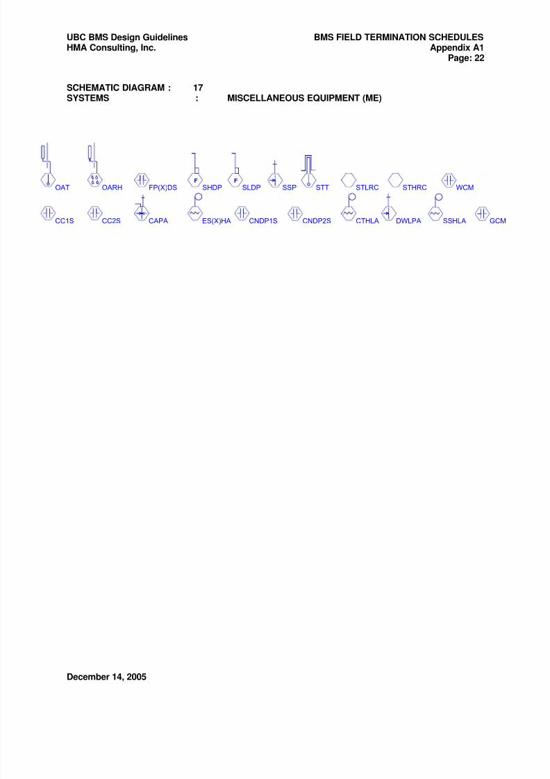
8/3/2019 15901-2008 Bms Ubc Bacnet Bms Master 14dec05 Final
http://slidepdf.com/reader/full/15901-2008-bms-ubc-bacnet-bms-master-14dec05-final 94/95
UBC BMS Design Guidelines BMS FIELD TERMINATION SCHEDULES HMA Consulting, Inc. Appendix A1
Page: 22
December 14, 2005
SCHEMATIC DIAGRAM : 17SYSTEMS : MISCELLANEOUS EQUIPMENT (ME)
OAT OARH FP(X)DS SHDPF
SLDPF
SSP STT STLRC STHRC WCM
GCMCC1S CC2S CAPA ES(X)HA SSHLACNDP1S CNDP2S CTHLA DWLPA
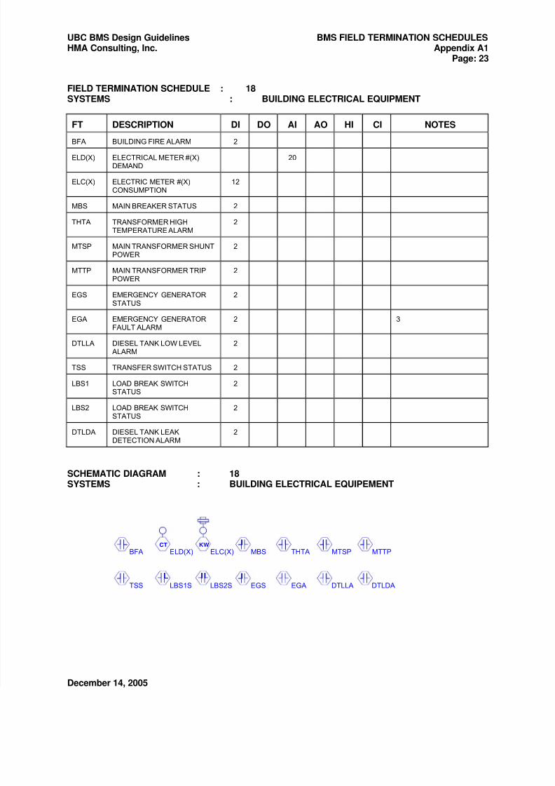
8/3/2019 15901-2008 Bms Ubc Bacnet Bms Master 14dec05 Final
http://slidepdf.com/reader/full/15901-2008-bms-ubc-bacnet-bms-master-14dec05-final 95/95
UBC BMS Design Guidelines BMS FIELD TERMINATION SCHEDULES HMA Consulting, Inc. Appendix A1
Page: 23
FIELD TERMINATION SCHEDULE : 18SYSTEMS : BUILDING ELECTRICAL EQUIPMENT
FT DESCRIPTION DI DO AI AO HI CI NOTES
BFA BUILDING FIRE ALARM 2
ELD(X) ELECTRICAL METER #(X)DEMAND
20
ELC(X) ELECTRIC METER #(X)CONSUMPTION
12
MBS MAIN BREAKER STATUS 2
THTA TRANSFORMER HIGHTEMPERATURE ALARM
2
MTSP MAIN TRANSFORMER SHUNTPOWER
2
MTTP MAIN TRANSFORMER TRIPPOWER
2
EGS EMERGENCY GENERATORSTATUS
2
EGA EMERGENCY GENERATORFAULT ALARM
2 3
DTLLA DIESEL TANK LOW LEVELALARM
2
TSS TRANSFER SWITCH STATUS 2
LBS1 LOAD BREAK SWITCHSTATUS
2
LBS2 LOAD BREAK SWITCHSTATUS
2
DTLDA DIESEL TANK LEAKDETECTION ALARM
2
SCHEMATIC DIAGRAM : 18SYSTEMS : BUILDING ELECTRICAL EQUIPEMENT