Augmented Reality for Maintenance and Repair (ARMAR)
70
AFRL-RH-WP-TR-2007-0112 Augmented Reality for Maintenance and Repair (ARMAR) Steven J. Henderson Steven K. Feiner Columbia University Department of Computer Science 500 West 120 th St., 450 CS Building New York NY 10027-7003 August 2007 Final Report for June 2005 to August 2007 Air Force Research Laboratory Human Effectiveness Directorate Warfighter Readiness Research Division Logistics Readiness Branch Wright-Patterson AFB OH 45433-7604 Approved for public release; distribution is unlimited.
Transcript of Augmented Reality for Maintenance and Repair (ARMAR)

AFRL-RH-WP-TR-2007-0112 Augmented Reality for Maintenance and Repair (ARMAR)
Steven J. Henderson Steven K. Feiner
Columbia University Department of Computer Science
500 West 120th St., 450 CS Building New York NY 10027-7003
August 2007
Final Report for June 2005 to August 2007
Air Force Research Laboratory Human Effectiveness Directorate Warfighter Readiness Research Division Logistics Readiness Branch Wright-Patterson AFB OH 45433-7604
Approved for public release; distribution is unlimited.

NOTICE Using Government drawings, specifications, or other data included in this document for any purpose other than Government procurement does not in any way obligate the U.S. Government. The fact that the Government formulated or supplied the drawings, specifications, or other data does not license the holder or any other person or corporation; or convey any rights or permission to manufacture, use, or sell any patented invention that may relate to them. This report was cleared for public release by the 88th Air Base Wing Public Affairs Office and is available to the general public, including foreign nationals. Copies may be obtained from the Defense Technical Information Center (DTIC) (http://www.dtic.mil). THIS REPORT HAS BEEN REVIEWED AND IS APPROVED FOR PUBLICATION IN ACCORDANCE WITH ASSIGNED DISTRIBUTION STATEMENT.
AFRL-RH-WP-TR-2007-0112 //SIGNED// CHRISTOPHER M. BURNEKA Work Unit Manager Logistics Readiness Division //SIGNED// DANIEL R. WALKER, Colonel, USAF Chief, Warfighter Readiness Research Division Human Effectiveness Directorate Air Force Research Laboratory This report is published in the interest of scientific and technical information exchange, and its publication does not constitute the Government’s approval or disapproval of its ideas or findings.

REPORT DOCUMENTATION PAGE Form Approved
OMB No. 0704-0188 Public reporting burden for this collection of information is estimated to average 1 hour per response, including the time for reviewing instructions, searching existing data sources, gathering and maintaining the data needed, and completing and reviewing this collection of information. Send comments regarding this burden estimate or any other aspect of this collection of information, including suggestions for reducing this burden to Department of Defense, Washington Headquarters Services, Directorate for Information Operations and Reports (0704-0188), 1215 Jefferson Davis Highway, Suite 1204, Arlington, VA 22202-4302. Respondents should be aware that notwithstanding any other provision of law, no person shall be subject to any penalty for failing to comply with a collection of information if it does not display a currently valid OMB control number. PLEASE DO NOT RETURN YOUR FORM TO THE ABOVE ADDRESS. 1. REPORT DATE (DD-MM-YYYY)
August 2007 2. REPORT TYPE
Final 3. DATES COVERED (From - To) June 2005 – August 2007
4. TITLE AND SUBTITLE Augmented Reality for Maintenance and Repair (ARMAR)
5a. CONTRACT NUMBER FA8650-05-2-6647
5b. GRANT NUMBER
5c. PROGRAM ELEMENT NUMBER 62202F
6. AUTHOR(S) Steven J. Henderson, Steven K. Feiner
5d. PROJECT NUMBER
5e. TASK NUMBER
5f. WORK UNIT NUMBER 1710D225
7. PERFORMING ORGANIZATION NAME(S) AND ADDRESS(ES)
8. PERFORMING ORGANIZATION REPORT NUMBER
Columbia University Department of Computer Science 500 West 120th St., 450 CS Building New York NY 10027-7003
9. SPONSORING / MONITORING AGENCY NAME(S) AND ADDRESS(ES) 10. SPONSOR/MONITOR’S ACRONYM(S) Air Force Materiel Command AFRL/RHAL Air Force Research Laboratory Human Effectiveness Directorate Warfighter Readiness Research Division
11. SPONSOR/MONITOR’S REPORT NUMBER(S)
Logistics Readiness Branch AFRL-RH-WP-TR-2007-0112 Wright-Patterson AFB OH 45433-7604
12. DISTRIBUTION / AVAILABILITY STATEMENT Approved for public release; distribution is unlimited. 13. SUPPLEMENTARY NOTES 88TH ABW/PA cleared on 11/14/2007, WPAFB-07-0432
14. ABSTRACT The purpose of this research, Augmented Reality for Maintenance and Repair (ARMAR), was to research the design and development of experimental augmented reality systems for maintenance job aiding. The goal was to explore and evaluate the feasibility of developing prototype adaptive augmented reality systems that can be used to investigate how real time computer graphics, overlaid on and registered with the actual equipment being maintained, can significantly increase the productivity of maintenance personnel, both during training and in the field.
15. SUBJECT TERMS Augmented Reality for Maintenance and Repair (ARMAR), Computer Graphics, Job Aiding, Maintenance, Distributed Collaboration 16. SECURITY CLASSIFICATION OF:
17. LIMITATION OF ABSTRACT
18. NUMBER OF PAGES
19a. NAME OF RESPONSIBLE PERSON Christopher M. Burneka
a. REPORT UNCLASSIFIED
b. ABSTRACT UNCLASSIFIED
c. THIS PAGE UNCLASSIFIED
SAR
68
19b. TELEPHONE NUMBER (include area code)
Standard Form 298 (Rev. 8-98) Prescribed by ANSI Std. 239.18
i

THIS PAGE LEFT INTENTIONALLY BLANK
ii

iii
Contents
1. Introduction............................................................................................................................ 1
1.1. Scope ........................................................................................................................................... 1
1.2. Background ................................................................................................................................ 1
1.3. Research Objectives .................................................................................................................. 1
1.4. Research Approach ................................................................................................................... 2
1.5. Research Environment.............................................................................................................. 3
2. Problem Definition................................................................................................................. 4
2.1. History of the Problem and Present System............................................................................ 4
2.2. Proposed Problem Statement ................................................................................................... 4
3. AR Concept Exploration........................................................................................................ 5
3.1. AR Background ......................................................................................................................... 5 3.1.1. Early Work.............................................................................................................................................5 3.1.2. Applications of Interest to Maintenance Job Aiding..............................................................................7
3.1.2.1 AR Applications in Maintenance and Assembly..........................................................................7 3.1.2.2 AR Applications in Training ......................................................................................................11
3.2. Generalized AR System Design Concepts ............................................................................. 11
3.3. AR Design for Maintenance Job Aiding................................................................................ 13 3.3.1. Tracking...............................................................................................................................................13 3.3.2. Registration..........................................................................................................................................20 3.3.3. AR Display Technologies for Maintenance Job Aiding ......................................................................21 3.3.4. Graphics Rendering .............................................................................................................................26 3.3.5. Interaction Devices and Techniques ....................................................................................................27 3.3.6. Presentation..........................................................................................................................................28 3.3.7. Authoring.............................................................................................................................................30 3.3.8. Application Design ..............................................................................................................................30 3.3.9. User Level Design Concepts................................................................................................................31
3.4. Potential Benefits of AR in Maintenance Job Aiding........................................................... 32
3.5. Potential Limitations of AR in Maintenance Job Aiding..................................................... 34
3.6. Proposed Target Domains and Tasks .................................................................................... 35

iv
3.7. Summary of Findings and Recommendations ...................................................................... 36
4. Prototype Design .................................................................................................................. 39
4.1. ARMAR Client ........................................................................................................................ 39 4.1.1. User Interface Controller .....................................................................................................................39 4.1.2. Maintenance Procedure Controller ......................................................................................................41 4.1.3. Object Tracking Controller ..................................................................................................................41 4.1.4. Data Management Controller...............................................................................................................42
4.2. ARMAR Server ....................................................................................................................... 42
4.3. Prototype Demonstration: Removing the Oil Pressure Transducer................................... 43
4.4. Augmented Controls: A Prototype User Interaction Technique......................................... 45
5. References ............................................................................................................................ 59

v
List of Figures
Figure 1. Rolls-Royce Dart 510 prototype component in Columbia University CGUI Lab .......... 3
Figure 2. Knowledge Based Augmented Reality (KARMA) [15] ................................................. 6
Figure 3. Annotating an engine with AR [37] ................................................................................ 8
Figure 4. AR in architectural inspection (left) and construction (right) [42].................................. 9
Figure 5. ARTESAS maintenance application [45]...................................................................... 10
Figure 6. Generalized design for AR applications........................................................................ 12
Figure 7. Marker-based tracking with ARTag.............................................................................. 16
Figure 8. InterSense InertiaCube3 hybrid inertial-magnetic tracker ............................................ 17
Figure 9. InterSense IS-900 hybrid interial-acoustic tracker ........................................................ 18
Figure 10. InterSense IS-1200 (beta) hybrid inertial-optical tracker............................................ 19
Figure 11. Sony LDI-D100B optical see-through display (with added camera and ruggedized
mount) ........................................................................................................................................... 23
Figure 12. InnerOptic Vidsee video see-through display (shown with IS-1200 beta tracker) ..... 24
Figure 13. ARMAR prototype design........................................................................................... 40
Figure 14. ARMAR prototype demonstration .............................................................................. 43
Figure 15. ARMAR prototype demonstration screenshot ............................................................ 44
Figure 16. Augmented controls interface area.............................................................................. 46
Figure 17. User activates repair menu .......................................................................................... 47
Figure 18. User selects repair procedure....................................................................................... 48
Figure 19. System loads first step and hides menu....................................................................... 49
Figure 20. User cues for next step ................................................................................................ 50
Figure 21. Example binary image................................................................................................. 51
Figure 22. Mapping interface coordinates to gestures .................................................................. 54
Figure 23. Augmented controls state diagram .............................................................................. 57

THIS PAGE LEFT INTENTIONALLY BLANK
vi

1
1. Introduction
1.1. Scope
The high-level objective of this contract, Augmented Reality for Maintenance and Repair
(ARMAR), was to research the design and development of experimental augmented reality
systems for maintenance job aiding. The goal was to explore and evaluate the feasibility of
developing prototype adaptive augmented reality systems that can be used to investigate how
real time computer graphics, overlaid on and registered with the actual equipment being
maintained, can significantly increase the productivity of maintenance personnel, both during
training and in the field.
1.2. Background
Augmented reality (AR) refers to the generation of 3D graphics or other media such that they
are overlaid on and registered with surrounding objects in the environment. Applying AR to
maintenance tasks could make it possible for users to be trained for those tasks, and actively
assisted during their performance, without ever needing to refer to separate paper or electronic
technical orders. Incorporating instruction and assistance directly within the task domain, and
directly referencing the equipment at which the user is looking, could eliminate the current need
for personnel to continually switch their focus of attention between the task and its separate
documentation.
1.3. Research Objectives
Our research program had the following objectives:
• Investigate the feasibility of developing prototype adaptive AR systems that can be used
for flight line maintenance.
• Examine the effects of productivity of maintenance personnel when such adaptive AR
systems are incorporated into flight line maintenance.

2
• Enumerate the open research questions in software and computing system support for AR
technologies.
• Investigate the requirements for generating 3D graphics that can be overlaid on
surrounding objects in the actual physical environment.
• Research the design and development of a prototype adaptive AR system that permits
virtual training and task animations within a consistent user interface.
• Identify one or more maintenance task domains of interest, and select maintenance job
aiding activities to address within these domains.
• Evaluate and determine appropriate displays, interaction devices, and position/orientation
tracking technologies that could be employed in the design and development of prototype
AR maintenance job aids for the tasks and activities.
1.4. Research Approach
Our research methodology for this work followed a three-step process: problem definition,
AR concept exploration, and prototype design. In our problem definition, we formally articulate
the general maintenance job aiding problem that potentially requires an AR-based solution. In
AR concept exploration, we examine various AR concepts, technologies, and techniques vis-à-
vis maintenance job aiding. This includes a detailed discussion of AR hardware and software
and their advantages, disadvantages, and open research questions. We then provide a look at
potential benefits and limitations of AR application in maintenance job aiding. This includes
offering specific maintenance task domains and activities that are well suited for AR.
In prototype design, we offer an initial high-level design for an AR-based maintenance job
aiding system. This design embodies one possible approach to an adaptive AR system that could
combine virtual training and field use in a consistent interface.

3
1.5. Research Environment
This work was conducted within the Computer Graphics and User Interface (CGUI) Lab in
the Columbia University Department of Computer Science. The CGUI Lab has a wide variety
of tracking and display technologies, and computer graphics hardware and software, and has a
long tradition of research in AR theory and practice. To address the specific needs of an
investigation into flight line maintenance, we acquired and refurbished a Rolls-Royce Dart 510
turboprop engine (Figure 1), which has served as a test-bed for the analysis and concepts
presented in this report.
Figure 1. Rolls-Royce Dart 510 prototype component in Columbia University CGUI Lab

4
2. Problem Definition
2.1. History of the Problem and Present System
Current maintenance systems require even the most experienced user to continually reference
prints, manuals, or computers that detail maintenance procedures, component data, and safety
information. These artifacts must be held or placed within the maintainer’s environment, often
outside of the maintainer’s field of view of the repair area. This causes the maintainer to
constantly switch their focus (context) from the repair area to the references and back again.
During this process, the maintainer must synthesize the information from the references and
apply it spatially and conceptually to a particular view of the repair area. This process includes
filtering references for relevant information, matching objects in the references to their real
world counterparts, and identifying variations between the two views.
Modern aircraft, vehicles, and other equipment exacerbate this problem. These complex
systems comprise numerous digital components that generate torrents of information that
maintainers must factor into inspection, troubleshooting, and repair procedures. Many agencies
realized this in the 1990s, spawning the Interactive Electronic Technical Manual (IETM). The
IETM replaced stacks of paper manuals and reports with a single mobile computer whose user
interface linked multiple sources of information into a single application.
However, despite their efficiency at bringing multiple references into a computerized
interface, IETMs are still external to the interaction between the maintainer and the equipment
he/she is maintaining. This separation increases the overall time of the repair, injects errors into
the repair process, and increases the cognitive load on the maintainer.
2.2. Proposed Problem Statement
Based on this background, and our research goals, we propose the following problem
statement to guide our work:

5
Provide maintenance and repair assistance and training to users performing maintenance
tasks, actively assisting in their performance, without ever requiring them to refer to
separate paper or electronic technical orders. Incorporate instruction and assistance
directly within the task domain, visually integrated with the equipment the user is
maintaining.
3. AR Concept Exploration
3.1. AR Background
An AR system is formally defined by Azuma and colleagues [2] as a system that
“supplements the real world with virtual (computer generated) objects that appear to coexist in
the same space as the real world.” These systems have three defining properties: (1) they
combine real and virtual objects in a real environment, (2) they run interactively; and in real
time; and (3) they register (align) real and virtual objects with each other. AR is a well
researched science with direct application to the maintenance job aiding domain. In this section,
we briefly review the theoretical underpinnings of AR, introducing several key research projects
that are relevant to the system under study.
3.1.1. Early Work
AR emerged as a named field in computer science in the 1990s, as advances in computer
hardware led to development of affordable computer systems capable of rendering tracked
virtual content in the form of compelling real time graphics [42]. However, the most
fundamental AR concepts and technologies date back to the early days of computer graphics
research. From the late 1960s to the early 1970s, Sutherland and his students, working at
Harvard and the University of Utah, developed the first position- and orientation-tracked see-
through head-worn display (HWD) that overlaid graphics on the user’s view of the world [40].
In the 1970s and 1980s, a small number of researchers studied AR at institutions such as the
USAF Armstrong Research Lab, the NASA Ames Research Center, and the University of North
Carolina at Chapel Hill.

6
In the early 1990s, Caudell and Mizell coined the term “augmented reality,” introducing
the idea of using an AR system to replace the large boards, paper templates, and manual
documentation used in constructing wire harnesses for complex airplanes such as the Boeing 747
[11]. This work resulted in several fielded experimental systems [30]. Feiner and colleagues
introduced the idea of Knowledge-based Augmented Reality for Maintenance Assistance
(KARMA), demonstrating a system for aiding a user in servicing a standard office laser printer
[15]. This system interactively generated 3D maintenance instructions using a rule-based
component that tracked the position and orientation of the user and selected objects in the
environment, and featured a tracked, optical see-though HWD that overlaid the instructions on
the user’s natural view of the task (Figure 2). Bajura and colleagues demonstrated a system that
allowed a user equipped with a HWD to view live ultrasound imagery overlaid on a patient [4].
Figure 2. Knowledge Based Augmented Reality (KARMA) [15]

7
3.1.2. Applications of Interest to Maintenance Job Aiding
3.1.2.1 AR Applications in Maintenance and Assembly
As mentioned above, maintenance and assembly tasks serve as natural applications
for AR. We attribute this to a variety of factors. First, these tasks typically demand maximum
preservation of a user’s focus on a specific area of interest. A second requirement is the need to
synthesize additional information, such as delicate and complex sequences, obtuse component
identification, and lengthy textual data. This synthesis is, in and of itself, difficult to place
directly in the context of the area of interest using classic techniques such as prints, manuals, or
laptops. Instead, these approaches at best visually replicate a separate annotated view of the area
of interest. Consequently, if the user refers to these kinds of documentation, they temporarily
switch focus (context) away from the actual area of interest to pictures and text describing it.
Regaining the original context, while simultaneously recalling and translating the newly
synthesized information, is burdensome. For these reasons, AR is especially applicable to the
areas of maintenance and assembly.
From the mid 1990s on, several additional projects, of various levels of maturity and
fielding, demonstrated this applicability and viability. Rose and colleagues developed a system
for annotating real-world objects using AR [37]. This system featured augmented part labeling
of an automotive engine, including the ability to label a part specified by the user with a tracked
stylus (Figure 3). A simplified 3D virtual model drives the labeling, using a z-buffer–based
visibility algorithm to determine whether a designated point on each part is visible; only if that
point is determined to be unoccluded in the current view, is the label for its part shown.

8
Figure 3. Annotating an engine with AR [37]
Researchers at Columbia University developed several AR prototypes that demonstrated
improved methods for the construction, inspection, and renovation of architectural structures
(Figure 4) [42]. One system, intended for inspection and maintenance, allowed a user wearing
a tracked optical see-through display to examine building infrastructure. A second system,
focusing on assembly, provided step-by-step overlaid instructions for assembling a spaceframe
structure composed of a set of struts and nodes.

9
Figure 4. AR in architectural inspection (left) and construction (right) [42]
Founded in the late 1990s, the ARVIKA consortium represented one of the largest
augmented and mobile AR research projects targeting the areas of maintenance and assembly.
This collaborative effort, funded by the German Ministry of Education and Research from 1999–
2003, developed augmented and mobile AR applications for general design, production, and
services in the automotive, aerospace, power processing, and machine tool production sectors
[18]. The Advanced Augmented Reality Technologies for Industrial Service Applications
(ARTESAS) project was a descendant of the ARVIKA consortium focusing on development of
user friendly AR applications for automotive or aerospace maintenance. A notable goal of the
ARTESAS project was the use of markerless tracking techniques in its applications, a move
aimed at mitigating the effects of the difficult surface and lighting systems that characterize
maintenance tasks. This work produced several prototype applications (Figure 5), which are
featured in a compelling video demonstration [45].

10
Figure 5. ARTESAS maintenance application [45]
A related effort by a team of researchers at metaio GmbH features a monocular optical
see-through display that communicates wirelessly to an AR application running on a standard
notebook. This application provides virtualized repair instructions, part labeling, and animation
for maintenance steps. The user’s head position and resultant field of view are calculated with a
markerless tracking algorithm that uses video images of the work area in conjunction with a
preprocessed CAD model of the equipment being maintained. This allows the user to perform
AR servicing and repair with little to no preparation of the environment [32].
Given the promising and noteworthy example applications introduced thus far, it is
important to note that no single AR system has emerged as a proven and industry accepted

11
solution to maintenance and assembly tasks. We offer possible explanation for this in Section
3.5.
3.1.2.2 AR Applications in Training
AR applications for training are especially interesting because many notable training
tasks are similar to maintenance job aiding. Additionally, these applications offer opportunities
for dual use, where hardware and software designs are shared for training and executing
particular tasks. As explained by Young et al., “One advantage of AR over more conventional
methods of providing additional information is that it can create a training environment without
major modifications to the operating interface, or without having to create expensive simulation
facilities.” [43]
Boulanger demonstrates one such application used for training repair of a
telecommunication switch [9]. In this system, users manipulate both tracked real components
and virtual components to train repairing an integrated circuit board. An interesting feature of
this work is the ability for several networked users to exchange views of the repair area,
supervise, and offer remote assistance.
3.2. Generalized AR System Design Concepts
AR applications have many important hardware, software, and human interface components.
The many variations possible in the design and implementation of these components lead to a
wide range of capabilities and limitations. Because of this variance, it is helpful to think about
AR systems according to a generalized design hierarchy.
Figure 6 depicts a generalized design, proposed by Bimber and Raskar, for an AR application
[6].

12
User
Application
Interaction Devices and Techniques Presentation Authoring
Tracking and Registration Display Technology RenderingBaseLevel
IntermediateLevel
ApplicationLevel
UserLevel
Figure 6. Generalized design for AR applications
The generalized design is comprised of four layers of components:
Base Level. This is the lowest level of design, and includes hardware and software designs
for tracking objects in the real world, displaying objects and information to the user, and creating
(rendering) computer-generated content. Most research effort to date in the field of AR has
occurred at this level.
Intermediate Level. This level of design, implemented mostly in software, is responsible for
interacting with the user, presenting and arranging generated content, and providing authoring
tools for creating AR applications. It is our belief, and the belief of other researchers, that this
level is only now beginning to emerge and contains many open research issues [35].
Application Level. This level, implemented entirely in software, consists of the overarching
AR application. It serves as the primary interface to the user.
User Level. This level represents the end user of the system. This level is included in the
generalized design to emphasize the user’s role in the application. AR applications are highly
dependent on human design issues, which must be considered independently of aggregate
interface design approaches.

13
3.3. AR Design for Maintenance Job Aiding
In this section, we decompose the generalized AR design into its various subcomponents, and
describe concepts, technologies, and techniques applicable to designing an AR system for
maintenance job aiding. For each component, we examine relevant advantages, disadvantages,
and open research questions. While we concentrate on maintenance job aiding, more
comprehensive overviews of AR concepts, technologies, and techniques can be found elsewhere
[2, 3].
3.3.1. Tracking
Tracking refers to the process of determining an object’s position and orientation in
physical space. This fundamental task, inherent to all AR applications, provides important
information for determining the state of objects (including the user) and their interactions.
Tracking real world objects is vital to registering virtual objects, such as labels, with their real
world counterparts. Additionally, tracking information might indicate a key interface activity,
such as a user pressing a virtual button. In this section, we present an overview of tracking
techniques relevant to maintenance job aiding tasks. A more comprehensive review of AR
tracking techniques and technologies is provided by Rolland and colleagues [36].
Tracking techniques are often classified using two taxonomies: the tracked object/sensor
relationship and the tracker’s underlying technology. The first taxonomy contains three classes:
inside-in, inside-out, and outside-in tracking [31]. Inside-in technologies represent relationships
where the tracked object and sensor are on the same body (e.g. a fiber-optic data glove). Inside-
out techniques use sensors that are fixed to the object and determine their position and
orientation from external emitters (either artificial or natural) in the environment. Global
Positioning System receivers are an example of this technique. Outside-in techniques use
sensors in the environment that track objects equipped with emitters. Classic sonar and radar
technologies use this technique. For maintenance job aiding tasks, we feel that inside-out
tracking techniques are the most applicable, based on mobility, size of the repair area, and
variability in repair locations.
14
Tracking technologies for indoor and outdoor use1 generally fall into six categories:
mechanical, inertial, electromagnetic, ultrasonic, optical, and hybrid. Mechanical tracking
systems use mechanical linkages tied to potentiometers and other electronic devices to determine
position and orientation. These systems provide extremely accurate position and orientation
information, often serving as the baseline for tracker performance tests, and were used in the first
AR system, developed by Sutherland. However, a principal disadvantage of these trackers is the
need for the mechanical apparatus that supports linkages and sensors, constraining the user’s
freedom of motion. We feel this renders most mechanical tracking technologies ill-suited for the
maintenance job aiding task.
Inertial tracking systems, which leverage the principle of linear and angular momentum
conservation, represent an important tracker class, given their compact size and ability to
function without an external source. However, since these systems tend to drift over relatively
short periods of time on their own, they are most useful when configured as part of hybrid
systems, which we discuss later.
Electromagnetic tracking systems employ sensors that determine their position and
orientation inside an artificially generated electromagnetic field. These systems are relatively
inexpensive and provide relatively high accuracy. However, these trackers are highly susceptible
to interference from ferrous metal, and magnetic fields, especially in dynamic environments in
which potential sources of interference are not stationary. For this reason, we do not view
electromagnetic trackers as viable alternatives for maintenance job aiding tracking requirements.
Ultrasonic tracking systems calculate position by measuring the time ultrasonic signals
from a set of transducers take to reach a set of microphones, assuming the speed of sound to be
known. These systems are also relatively inexpensive and provide a high level of accuracy; for
example, the 3D position and orientation of a set of three rigidly mounted microphones can be
determined based on the computed time of flight (and hence distance) to each microphone from
each of a set of three rigidly mounted transducers. Ultrasonic systems were among the earliest
trackers used in AR research, including Sutherland’s; however, they require a direct line of sight,
can suffer from interference from echoes and other sources, and have a relatively low update 1 In this report, we do not address outdoor-only applications, for which various kinds of GPS systems have been
used, or applications that require coarse (e.g., meter-level) tracking, for which RFID and infrared beacon
technologies are applicable.

15
rate. The only sufficiently high-quality systems currently available that use ultrasonic
technology do so in combination with other technologies to address these deficiencies, and will
therefore be discussed below with other hybrid trackers.
Optical tracking systems detect light (either visible or non-visible) directly emitted from
LEDs or other sources, or reflected. They include marker-based tracking systems, which use
video cameras to detect markers (predetermined black and white or colored patterns) positioned
at known locations in the environment (e.g., [10] [1] [16] [33]). Because CCD cameras and the
hardware and software needed to process digital video streams have become commodity items,
these systems are inexpensive and can provide a high level of accuracy. However, they require
controlled lighting, and line of sight between camera(s) and marker(s).
We maintain extensive experience with two marker-based systems that are widely used in
the field of AR: ARToolKit [1, 24] and ARTag [16]. Both of these use a CCD camera to detect
specialized markers, printed on standard computer printer. (While even web cameras intended
for home computers may be used, significantly better performance can be achieved by using
better quality COTS cameras.) The markers are fixed to coordinates and objects in the tracked
environment. Markers affixed to static points (e.g., aircraft components) can serve as anchor
points for overlaid content. Additionally, markers attached to movable objects, such as tools or
replacement parts, can be used to determine the position and orientation of these items in the
tracked environment, as well as anchor overlaid virtual content.
ARToolKit [1, 24] is an open-source framework allows developers to define their own
marker designs and train the tracking system to recognize them in the environment. However,
the extra vision recognition step required to recognize and differentiate among these designs in
real time impacts performance. In contrast, ARTag [16], uses a standard set of predetermined
patterns that uniquely encode the identity of each marker (Figure 7), and differs from ARToolKit
in a number of the algorithms it uses. In numerous experiments with ARTag, we have found it to
offer more highly responsive and accurate results in comparison with ARToolKit.
Since the tags themselves are passive (requiring no power) and inexpensive to produce,
marker-based trackers can work well in mobile environments. Therefore, we believe this type of
tracking technology is well suited for the development of proof-of-concept systems for the
maintenance job aiding task. A manageable number of markers attached to preregistered
locations in the area of a repair could serve as anchor points for labels, instructions, and other

16
virtual content. Likewise, markers attached to tools and replacement components would serve to
track the repair’s progress and user’s interactions. In most cases, maintenance units could install
these markers permanently (similar to UID markers or barcodes) without interfering with system
components. For cases when this were not possible, maintenance personnel could affix
temporary markers to predetermined mount points prior to a repair sequence.
Figure 7. Marker-based tracking with ARTag
Since marker-based tracking requires that markers be placed in the environment in
advance and remain sufficiently visible during a tracked task, research in optical tracking has
attempted to replace printed markers with natural features (such as visually unique parts of an
engine), making possible markerless tracking [7] [13]. (Several examples of markerless tracking
were discussed in Section 3.1.2.1.) It is the general consensus among researchers that optical

17
tracking will converge on this type of tracking. However, despite recent successes in the
laboratory, we feel these techniques are 3–5 years from maturing into robust, generalized toolkits
like those provided by ARToolKit and ARTag.
Hybrid tracking systems employ two or more of the previous types of tracking, and fuse
data to form a single estimate for location and/or orientation. These systems have the advantage
of redundancy, and can dynamically supplement the weaknesses of one tracking technology with
the strengths of another.
One hybrid tracking system that we have successfully used in outdoor mobile AR
systems is the InterSense InertiaCube3, which provides 3DOF orientation information by fusing
data from MEMS accelerometers, angular rate gyroscopes, and magnetometers (Figure 8).
However, this tracker does not work well in the presence of nearby moving ferromagnetic
objects, and is therefore ill suited for general maintenance job aiding tasks.
Figure 8. InterSense InertiaCube3 hybrid inertial-magnetic tracker
As part of this work, we tested two 6DOF hybrid systems that do not rely on magnetic
sensors: the inertial-acoustic InterSense IS-900 tracker and the inertial-optical InterSense IS-

18
1200 tracker (Figure 9). We found that the IS-900 provides very accurate position (< 0.5cm) and
orientation (< 1°) information for the user, as well as tracked components on our Dart 510
engine.2 However, these trials relied on carefully installed infrastructure attached to our lab
ceiling. Therefore, we cannot recommend this type of tracking solution for flight line
maintenance. However, such a system would be viable in a fixed maintenance facility such as an
aircraft hangar or job shop.
Figure 9. InterSense IS-900 hybrid interial-acoustic tracker
The InterSense IS-1200 (Beta) is an inside-out, hybrid inertial-optical tracker that fuses
location and orientation data from a wide-angle camera with orientation data reported from a
collocated inertial unit [17]. The system operates by recognizing specially designed markers
2 All figures given for this and other trackers are conservative values obtained in our lab over a wide range of
operating conditions.

19
(fiducials), printed on standard printer paper, similar in concept to those used in pure marker-
based systems. In our work, we installed these fiducials on the ceiling of our lab, and used the
tracker to report the position and orientation of the user’s head (Figure 10). This information was
combined with a 3D model of the engine (registered to the environment) to allow prototype part
labeling. This approach yielded highly responsive tracking results with high levels of accuracy (<
0.5cm position, < 0.5° orientation) and no interference from the engine or other components in
the environment. The tracker’s hybrid design also made it resilient to intermittent variations in
lighting, as well as rapid head movements. Because of these results, we feel this tracking
technology is well suited for tracking the head position and orientation of the user conducting a
maintenance job aiding task. For flight line environments, large surfaces on the system being
maintained could serve as mounting points for markers. Alternatively, fiducials could be
mounted on lightweight rigid frames that are attached to predetermined points on the maintained
system.
Figure 10. InterSense IS-1200 (beta) hybrid inertial-optical tracker

20
3.3.2. Registration
In order for AR applications to merge virtual objects with real objects, the two sets of
objects must be properly located and aligned. This process is known as registration and, based
on our analysis, represents the biggest theoretical and technological obstacle to creating an
effective AR system for maintenance job aiding. This is due to the precision needed in many
maintenance tasks. For example, if a mechanic adjusts a pitch change link on a helicopter rotor
by moving the retaining nut to a virtualized marker, a 5 mm error in registration could cause the
mechanic to under adjust the nut, nullifying the repair.
Registration errors typically result from five sources: distortion in the display,
imperfections in the virtual 3D model, mechanical misalignments (in the tracker or display
mounting), incorrect display settings, and tracking errors. In the field of maintenance job aiding,
all of these are manageable, with tracking errors being the most problematic. These typically
nondeterministic errors are largely influenced by fixed third party hardware or software
implementations.
It is a common assumption that registration errors will reduce with improving tracking
technologies. Recent work by Coelho, Julier, and MacIntyre challenges this assumption and
proposes an alternative to relying on the future promise of better tracking technology [12]. Their
OSGAR framework integrates registration error management directly into the rendering of
virtual content. Registration error estimates are calculated and propagated throughout an
underlying 3D model, and virtual content is controlled and constrained according to various error
levels. For example, if the location of a particular component becomes suspect, the system may
replace a label previously identifying that component with a coarser label tied to a larger (and
less error-sensitive) parent.
Based on our work in this project, we feel AR applications for maintenance job aiding
should adopt this realistic view of registration errors. If a mechanic is conducting a repair in an
augmented environment, a level of error filter could alert the user (virtually) of degradation in
registration. This could result in an explicit warning (similar to cell phone signal strength bars)
or an implicit warning in the form of a graceful degradation in performance (similar to speed
restrictions on congested internet file downloads). The mechanic could then continue the repair,
taking requisite steps to supplement the loss in performance.

21
3.3.3. AR Display Technologies for Maintenance Job Aiding
Display technologies in AR perform the important tasks of merging virtual and real world
environments. Two display characteristics important to AR applications are display resolution
and stereoscopy. Display resolution determines the level of detail available for generating virtual
content in optical see-through displays, and both virtual and real world content in video see-
through displays. Stereoscopy provides depth cues to the user and is important in performing
tasks that involve arm’s length distance judgements.
Display technologies fall into three general categories: head-worn, handheld, and
projective. Head-worn displays (HWDs) are mounted on the user’s head and present AR in front
of one eye (monocular) or both eyes (biocular if the images presented to both eyes are the same,
binocular if the images presented to both eyes form a stereo pair). HWDs are further categorized
according to how they combine views of the real and virtual worlds [29]. Optical see-through
displays provide the user with a direct view of the real world (mediated only by optical
elements), and overlay virtual content on top of this view. The real and virtual worlds are merged
using optical combiners, such as half-silvered mirrors or prisms. Video see-through displays use
cameras to capture real world imagery, combine the real and virtual content digitally or through
videomixing hardware, and present it on the same displays.
Optical see-through displays have the advantage of presenting the real world at its full
spatial resolution, with no temporal lag, full stereoscopy, and no mismatch between vergence
(the angle between the lines of sight from each eye to a given real world object) and
accommodation (the distance at which the eyes must focus to perceive that real world object).
However, some luminance is lost because of the reflectivity of the combiner, and many early
designs included additional filtration to avoid overwhelming the relatively dim displays used for
the virtual world. In addition, commercially available optical see-through displays cannot
selectively suppress the view of any part of the real world, so bright real world objects can be
seen through virtual objects that are in front of them, even when the virtual objects are supposed
to be opaque. (One experimental system has overcome this obstacle by introducing a liquid-
crystal matrix and additional optics in the optical path to the real world, allowing selectable areas
of the real world to be blocked [25].) The lag-free view of the real world also emphasizes the lag
that occurs in presenting the virtual world.

22
In contrast, video see-through displays have the advantage of allowing essentially
arbitrary processing of both the real and virtual worlds, making it possible to render virtual
objects that fully obscure real ones. However, the real world is rendered at less than full
resolution. Furthermore, because all imagery is typically presented on one display at a fixed
perceived distance, both the real and virtual imagery will typically suffer from a vergence-
accommodation mismatch, often resulting in visual discomfort and misjudgement of distances,
although this can be minimized if the system is designed and used for content viewed at a
preselected distance.
We tested a (now discontinued) Sony LDI-D100B stereo optical see-though display,
shown in Figure 11, for viability in the maintenance job aiding task. While its 800×600
resolution and approximately 30° horizontal field of view were sufficient for near-field tasks, the
neutral density filters that it incorporates to compensate for its relatively dim LCD displays
makes it difficult to see the repair area without the use of significant additional task lighting.
More recent optical see-through displays use brighter displays and relatively transmissive
optics (ca. 50%), but current commercial systems are split between lightweight (< 100g),
relatively inexpensive (< $10K), monocular devices with a relatively small field of view (< 30°),
such as the Liteye 500 and 750, and heavier (> 1000g), relatively expensive ($35K– $100K)
stereo displays with a relatively wide field of view (> 35°), such as the nVis nVisor ST,
Rockwell Collins ProView XL50, and SaabTech AddVisor 150. These stereo optical see-
through displays were outside the budget available for this work, but we have evaluated all of
them in vendor demonstrations, and believe that that they are optically well suited for job
maintenance aiding, although far bulkier than users would prefer.
Among the monocular see-through displays we evaluated, the Liteye 500 provides a
crisp, but small image, with the advantage of manually adjustable focus. (The Liteye 2020, an
announced, but not yet available, binocular product, may be a good candidate for a relatively
inexpensive stereo optical see-through testbed.) We also evaluated a Lumus PD-10 800×600
resolution monocular display, whose small size and lack of an opaque “frame”, provides the
closest experience to an eyeglass form factor, and were sufficiently impressed to place an order
in early 2006. While the company has unfortunately been unable to deliver because of
production difficulties, the PD-10, and newer binocular prototypes, remain interesting.

23
Figure 11. Sony LDI-D100B optical see-through display (with added camera and ruggedized mount)
Optical see-through displays include a special class of display known as virtual retinal
displays. These systems have been developed and commercialized by Microvision, and display
virtual content reflected from half-silvered optics onto the user’s retina using low-powered eye-
safe lasers [28]. However, the only affordable versions commercially available thus far have
been monocular, red-scale systems, such as the Nomad 1000 that we have in our lab. While
extremely bright and transmissive, they have a relatively low contrast ratio, and we have also
found that many potential users appear to be psychologically uncomfortable with the idea of
using a laser display. Microvision is no longer producing these displays at this time, but is
developing a small color display, which could be a viable option for the maintenance job aiding
task.

24
As part of our work on ARMAR, we procured and have tested an InnerOptic Vidsee
video-see through display [39]. This display was originally developed for use in research
projects in augmented surgery at UNC Chapel Hill. The Vidsee supplements a Sony Glasstron
LDI-D100B with a fixed dual mirror assembly containing a pair of cameras that is designed to
provide parallax-free image capture—the cameras are virtually located at the same position and
can share the same field of view as the user’s eyes (Figure 12). In contrast, earlier video see-
through displays often positioned cameras above, or otherwise at different locations than, the
wearer’s eyes. Using the Vidsee display, we present the user with combined real and virtual
stereo content stereo at 800×600 resolution, thirty frames per second, creating a compelling
experience of an augmented workspace. Based on our preliminary experience, we believe that
this family of displays represents a viable display technology for the maintenance job aiding
task, supporting a range of lighting conditions and the ability to present fully opaque virtual
objects that is the hallmark of video see-through displays.
Figure 12. InnerOptic Vidsee video see-through display (shown with IS-1200 beta tracker)

25
We see two sets of factors currently constraining the use of HWDs in the area of
maintenance job aiding. The first set of factors is a function of optical properties, including
resolution, color capability, field of view, transmissivity, and stereoscopy. Based on our
experience, we recommend maintenance job aiding tasks use color, stereoscopic displays with a
resolution of at least 800×600 pixels, a horizontal field of view of at least 30°, and, if optical see-
through, a transmissivity of at least 35%, or if video see-through, relatively parallax-free optics.
Unfortunately, few commercially available HWDs meet these requirements, and price and
physical bulk currently increase significantly for devices that exceed them.
The second set of factors is a function of the size, weight, and appearance of these
devices. All stereoscopic HWDs that currently meet our resolution requirements are
significantly larger and heavier than a pair of standard eyeglasses, the proverbial gold standard
for mainstream acceptance of this technology. Larger and heavier displays risk limited
acceptance of these devices, particularly in maintenance domains where safety concerns can
restrict any additional equipment worn by maintainers. However, we believe this acceptance risk
is manageable with proper scoping of the job aiding application, as described in Section 3.6.
Furthermore, we believe that the demands of consumer hand-held multimedia and
gaming devices will soon expand the market for affordable HWDs that meet the requirements
that we have suggested for maintenance job aiding. Support for this belief comes, in part, in the
success over the past year of opaque biocular displays, such as the myvu
(http://www.myvu.com), which is marketed to video iPod owners. This $299 HWD weighs 75g
and has dual 320×240 resolution color displays, which match the video resolution of the iPod. It
provides an image that has a wider field of view than the built-in display of the iPod, is private,
and does not require that the iPod be carried or placed within the wearer’s line of sight. As the
native resolutions of hand-held devices increase (e.g., the iPhone at 480×320, and the Toshiba
G900 Windows Mobile 6 smartphone at 800×400), we believe that a significant potential market
will be created for higher-resolution HWDs.
Handheld devices, including mobile phones, media players, portable game machines,
Tablet PCs, and Ultra-Mobile PCs (UMPCs), feature an LCD screen with one or more built-in
cameras. Like video see-through displays, these devices can capture images of the real world
and overlay them with virtual content, creating an experience that has been referred to as a

26
virtual window or magnifying glass [35]. Mobile phones are especially lightweight, and low
cost, with resolution and computational power increasing rapidly, and pixel density already more
than adequate. However, the small physical field of view of many of these devices (often
mismatched with a wider camera field of view) and the need for hand-held operation currently
make them poorly suited for use as a primary display in maintenance job aiding. Nevertheless,
they could play auxiliary roles as input devices or special viewing devices [19].
Projective displays project virtual content directly onto the real world [6]. The
advantages of this approach include the ability to view an augmented environment without
wearing a display or computer. (Although head-worn projective displays have been developed,
they are designed for projection onto retroreflective surfaces, ruling out typical maintenance
domains.) Bright projectors combined with relatively reflective task surfaces can make this a
good approach for certain domains. However, these systems typically assume that all virtual
material is intended to lie on the projected surface, limiting the kind of geometry that can be
presented. Stereo projection is possible, in conjunction with special eyewear or the use of optical
combiners in the environment, often in conjunction with head tracking, but this removes the
appeal of not requiring special eyewear or modifications to the environment. For these reasons,
we do not believe these displays will be as generally useful as HWDs for maintenance job aiding
tasks.
3.3.4. Graphics Rendering
Graphics rendering refers to the low-level computation required to generate virtual
content. This process is typically handled by commodity computer graphics cards, and is
normally transparent to a particular application. Our experience with ARMAR and other recent
AR applications confirms our belief that there are no graphics rendering issues precluding the
use of AR in the maintenance job aiding domain. However, we temper these findings with the
following considerations.
Initially, researchers characterized the graphics requirement for AR applications as light.
Most early AR applications, due to constraints in other areas, featured a relatively small number
of 3D objects, wireframe drawings, and labels [3]. However, given improvements in tracking
techniques and display technologies, AR applications are demanding more graphics capability,
even though requirements are significantly lower than for fully synthesized environments. In

27
particular, textured high fidelity 3D models and video see-through displays represent two high
demand consumers of computer graphics throughput.
Several comprehensive frameworks exist to help meet this demand, most notably
OpenGL and Direct3D (Microsoft Direct X). These graphics frameworks are supported directly
in most higher-end graphics cards, and provide such features as z-buffering, anti-aliasing, alpha
blending, texture mapping, and atmospheric effects. We recommend any AR application for
maintenance job aiding build on the capabilities of either of these two frameworks.
3.3.5. Interaction Devices and Techniques
Interaction devices and techniques represent the means for selecting and manipulating
virtual and real objects through the AR application. Because a definitive, standardized set of
devices and techniques has yet to emerge for 3D user interfaces in general, let alone AR in
particular, we offer an analogy from 2D user interfaces for clarification. Modern 2D desktop
user interfaces, such as those of Windows and Mac OS, are built on the Windows, Icons, Menus,
and Pointing (WIMP) paradigm. Users rely on the knowledge that windows are containers for
applications and can be moved, sized, opened and closed by manipulating them with the mouse
(pointing device); icons represent minimized windows, files, and applications, and can also be
manipulated with the mouse; and additional interactions can be accomplished by using the
mouse to select actions and objects from menus.
AR applications could similarly benefit from having a standard, known set of user
interface devices and techniques. However a dominating set has yet to emerge. In this section,
we explore several techniques that we feel are especially useful for maintenance job aiding.
One technique, which we developed as a prototype and further describe in Section 4,
allows the user to manipulate an overlaid menu structure by using hand gestures to interact with
one or more augmented controls. An augmented control is an otherwise unexploited and safe
location in close proximity (arm’s reach) to the repair area, that provides a natural and intuitive
affordance for a desired user interface action. For example, a rotating washer on the housing of a
fuel pump being repaired might serve as a wheel the user turns to cycle through virtual pages
detailing the fuel pump’s repair procedure. When the user turns the washer to the right, a camera
detects this motion and advances the pages. Inside the AR application, virtual content such as an
animated arrow is overlaid on the washer to cue the user as to the washer’s wheel functionality.

28
This proposed technique is analogous to a 3D interaction technique introduced by Conner
and colleagues, where the user uses 3D widgets to manipulate an application [14]. These
widgets, which are displayed at any location in a 3D scene (including arbitrary points in space)
encapsulate geometry and behavior into a single virtual interaction device. In our proposed
technique, the geometry of these widgets is linked directly to actual surfaces in the environment,
leveraging the natural affordances and tangible feedback of physical objects.
Slay and colleagues introduced another potential technique of interest for the maintenance job
aiding task [38]. This technique uses a series of tracked markers as switches and pointers. A user
interacts with the system by selectively rotating or flipping over various tracked markers in the
interface area. The system determines the desired interaction based on the visibility, position,
orientation, and relationship of these markers. This interaction technique inherits the advantages
of marker-based tracking: low registration error, robust vision algorithms, and low cost. The
technique also features tangible objects that provide feedback to the user. A disadvantage of this
technique is the requirement to be responsible for these unfixed markers. One possible way to
address this could be to mount markers on standard tools and other common accessories, creating
dual-use interaction devices.
3.3.6. Presentation
The presentation layer in AR design uses primitives from the graphics rendering process
to create, arrange, and animate higher level objects that form virtual content delivered to the
display. These higher level objects include labels, connecting lines, arrows, 3D models, and
video. We cover three concepts that warrant special consideration in presenting virtualized
content to maintenance job aiding application: game engine software development kits, scene
graph application programming interfaces, and object labeling.
As we will discuss later in this report, game engine software development kits (SDKs) are
well suited for the development of maintenance job aiding applications. We mention them
separately here because their 3D object management and advanced rendering capabilities are
indispensable to the presentation of high quality virtual content. Based on our experience with
several game engines during the course of this work (described in Section 3.3.8), we recommend
that high quality AR job aiding applications should use game engine SDKs as the basis for all
virtual content presentation.

29
Scene graph application programming interfaces (APIs) represent another area of interest
for virtual content presentation. These APIs provide abstractions for creating, organizing, and
moving virtualized content for presentation. We tested one such API, OpenSceneGraph [47], as
part of ARMAR. The principal advantage of OpenSceneGraph is its robust suite of open-source
classes (written in C++) for managing 3D objects and cameras. These classes are well
documented, encapsulate many advanced functions, and are easily integrated into applications.
For example, we used this API and approximately thirty lines of our own C++ code to create a
simple prototype application for part labeling. This application supported two labels that
automatically faced the user (using OpenSceneGraph’s “billboard” class), and linked to physical
components via wireframe connectors. Despite their rich feature set and ease of use, we feel
scene graph APIs are a complementary, as opposed to comprehensive, technique for virtual
content presentation. They lack the sophistication and advanced rendering capabilities of game
engine SDKs, and would require heavy custom code augmentation to produce applications.
Our final highlighted consideration in this section addresses integrating virtual labels
(and other annotations) into an AR presentation scheme. This seemingly trivial task becomes
extremely complicated given the large number of labels potentially required in a maintenance job
aiding AR application. For each label, the application must determine:
• the visibility constraints specifying occlusion relationships between the label and real and
virtual objects in the user’s current view,
• the position of the label required to maintain minimum and maximum distances from
other objects,
• the size of the label required to maintain readability and reflect importance,
• the transparency of the label required to prevent occluding essential virtual and real-
world objects, and
• the priority of the label for display, as determined by relevant task filters and user
preferences.
To address these requirements in the maintenance job aiding application, we suggest
adopting the basic strategy proposed by Bell and colleagues [5]. This approach uses a separate
component known as a view management controller. This component employs algorithms that
keep track of occupied and unoccupied space in the user’s view of the scene, and dynamically
control the display layout to satisfy the current display constraints, based on the user’s view, the

30
configuration of objects in the scene, and the task. We believe this strategy is important based
on our experience with previous labeling problems and analysis of the job aiding task.
3.3.7. Authoring
Authoring refers to the need for robust, generalized software tools for designing AR
applications. Examples of existing research systems include [20] [21] and [44] with specific
applications of interest to maintenance job aiding featured in [22] and [27]. Although we did not
directly evaluate such systems as part of this project, our experience with AR authoring tools
shows them to be potentially viable approaches to the maintenance job aiding problem. These
tools offer several advantages, the most compelling being the ability of subject matter experts to
modify and customize applications with minimum need for programmer assistance. This allows
after-market modification of an application to fit specific or evolving requirements.
Additionally, if an authoring framework is well tested and integrated, it could free users from
low-level design issues posed by surrounding user interaction, presentation, tracking and display
functions.
3.3.8. Application Design
For the application layer of the maintenance job aiding tasks, we recommend leveraging
the power of game engine SDKs. These SDKs provide software interfaces and libraries that
allow developers to apply the functionality found in popular computer games directly to an AR
design. This functionality includes advanced 3D graphics rendering, complex material
modeling, collision detection, physics modeling, 2D user interface support, interfaces to 3D
modeling systems, human character modeling, and advanced sound rendering. This approach
can make possible high quality, fast, and visual appealing applications.
We experimented with several game engine SDKs as part of this work, the most notable
of which were Source by Valve Software [48] and the open-source Irrlicht engine [46]. Source
is a sophisticated and comprehensive game engine, used for the popular Half Life 2 and
Counterstrike first-person shooter games. The principal advantage of Source over many other
game engine SDKs is its superior graphics rendering engine. This engine, based on DirectX, is
extremely fast and features built in dynamic texturing (required for video see-through displays)
and occlusion texturing (important to allow real and virtual objects to occlude one another in the
final rendered image). Additionally, this SDK provides programming classes for networking,
31
complete management of any virtual object, and mapping tools for spatially arranging registered
3D objects. Moreover, because Source maintains lineage with popular mainstream video games,
it is very stable and reliable, and has a large developer community.
Source’s disadvantages include its complexity and partially closed libraries. Source has
over 100 poorly documented classes (written in C++), which make developing a Source-based
application daunting for any developer. Additionally, many of Source’s core components, such
as the rendering engine, exist as closed libraries that cannot be modified. However, despite these
disadvantages, we feel Source’s sophistication, performance, and wide acceptance make it an
excellent choice for development of a job aiding application.
The Irrlicht game engine SDK, which we also tested as part of this work, is a lightweight
open-source SDK written in C++. The engine maintains the principal advantage of being very
compact (< 30 MB of executable code), making it well suited for mobile platforms. The
rendering engine is also very fast, and applications designate at run-time whether to use either
OpenGL or DirectX graphics libraries. Several Java-wrapped versions exist, and the base C++
code for the engine is entirely open and very well documented. The principal disadvantage of
Irrlicht is its lack of integrated support for advanced texturing, occlusion, mapping, physics, and
character animation. However, we feel the engine is still viable for a maintenance job aiding
application.
3.3.9. User Level Design Concepts
In this section, we highlight several salient design concepts that pertain to the user level
of the generalized AR design. The first, which we partially described in Section 3.3.3, is user
acceptance of the application. Despite the issues involved with displays, an AR application
could face additional acceptance challenges in the maintenance job aiding domain. These
challenges are a function of social factors, and the natural instinct to resist change, particularly in
a high operations tempo, mission-critical, zero defects domain such as aviation maintenance.
The key to achieving acceptance entails incorporating the end user into the early stages of the
design process. Doing so, and thus giving the user authority in deciding among design
alternatives will help yield a system with the best chances for acceptance.

32
A second user-level concept, closely linked to the first, is the advantage of fielding any
AR maintenance job aiding application as a dual-use system for training maintenance tasks.
These types of systems have proven to significantly increase competency on maintenance and
assembly type tasks [8]. Moreover, such systems could naturally guarantee acceptance when
later used for actual repairs (either completely or partially). If a user is trained with an AR
system, they will naturally view the system as a supplement to any maintenance job aiding task.
By first exposing the user to the system entirely as a training device, and then gradually
incorporating more and more real world content, the user could become quite comfortable with
the system. These and other potential benefits are articulated by Young [43].
Based on our analysis, we feel that a dual-use system could be easy built if a game engine
SDK serves as the foundation for the application. One could configure such a system to run
entirely as virtual reality application, in which the entire task domain is presented solely through
the computer, with little additional load on the underlying engine.
3.4. Potential Benefits of AR in Maintenance Job Aiding
Based on our experience and targeted research in this project, we have identified the
following potential benefits as the most salient in using AR applications for maintenance job
aiding:
• Reduced head and eye movement. Overlaying virtual versions of content normally
presented in manuals, prints, laptops, and other off-plane references could greatly reduce
the movement of the maintainer’s eyes and head. This could decrease the maintainer’s
work load, potentially improving health, efficiency, and endurance [41].
• Reduced context switching. Overlaying virtual content can allow the user to maintain
their focus (context) on the repair area. This could increase productivity, as it allows a
maintainer to synthesize supporting information and make decisions within in a single,
constant, and spatially accurate mental model.
33
• Reduced time for repair sequence transitions. AR applications can provide helpful cuing
information, such as labels, arrows, and other artifacts to aid the maintainer in physically
negotiating a repair sequence. This could reduce the transition time required for a
maintainer to move among spatially extended subtasks, potentially shortening the overall
repair time.
• Real time collaboration. The AR application could push tracked information for the
maintainer, tools, repaired components, and repair parts over a shared network. This
information could include streaming video from head-worn cameras or the merged output
of a video see-through display. This data would enable remote users to remotely monitor
the repair and virtually render remote assistance.
• Historical documentation. Archived tracking data and captured display imagery could
aid in recreating past repair sequences. This information can provide helpful auditing
information for accident investigation and training evaluation.
• Complementary training application. AR systems for job aiding, particularly those built
on robust gaming technologies, could operate across a wide continuum of virtual to real
content, while preserving a common software and hardware architecture. This would
support a variety of training techniques. For example, using only virtual content would
allow training scenarios to run entirely in virtual reality. Alternatively, the application
could use maximum levels of real world content, supplemented with virtual objects to
train various contingencies. This includes injecting artificial contingencies directly into
ongoing repairs to take advantage of maintenance conditions that do not normally occur
(similar to simulated battle drills or emergency procedures). We emphasize that all of
these training modes would share a common set of hardware and software.

34
3.5. Potential Limitations of AR in Maintenance Job Aiding
Based on our experience in AR research and work on this project, we view the following as
the main inhibitors to effective AR applications for maintenance job aiding:
• Availability of small/lightweight HWDs with adequate resolution. As described in
Section 3.3.3, the limited availability of HWDs matching our recommended criteria for
job aiding tasks restricts the hardware design space for this problem. This will limit the
development of AR applications for maintenance job aiding until such displays become
more widely available and accepted.
• Registration errors. As described in Section 3.3.2, registration errors limit the level of
spatiotemporal accuracy available for AR applications. Even with the tracking and error
management techniques suggested in this report, a lower bound on the types of activities
performed with an AR application will always exist, based on the accuracy required. An
effective AR application must avoid this lower bound, and include a system for
successfully managing any registration errors.
• System acceptance. As described in Section 3.3.9, AR systems risk rejection by
individual users and the maintenance community as a whole. Improvements in HWDs
(reducing size and weight) are needed to offset this risk. Additionally, any task domains
must consider legitimate safety concerns surrounding the presence of AR equipment. For
example, HWDs could potentially limit a user’s awareness of obstacles and other
dangers. Likewise, cables and equipment might snag on the repair environment,
potentially injuring the user. To address these and other acceptance issues, the
development of AR applications should include the end user early in the design process
to ensure usability and buy in.
• Data integration. The detailed 3D modeling required to generate virtual content in an
AR system for maintenance job aiding will bound the application’s applied scope.
Providing an application that supports a wide range of repairs is not feasible without

35
significant efforts at modeling components to be maintained and integrating this data into
a standardized format for storage and repair [34]. In our experience, such 3D models are
not widely available from manufacturers, requiring significant after-market modeling
using expensive 3D scanners and manual processing.
• Complexity. With any new technology, there exists a tendency to apply it ambitiously to
a wide range of problems and settings. At this time, such an approach could undermine
the success of AR applications in the maintenance arena. Instead, design efforts must
focus on relatively simple and targeted applications that provide high functionality and
tangible results.
• Value modeling. Little theoretical work exists documenting the value added by AR to the
maintenance job aiding task. Researchers must furnish tangible evidence to convince
decision makers and maintenance communities of the value an AR approach provides in
productivity, accuracy of repair, and user effectiveness.
3.6. Proposed Target Domains and Tasks
Based on these potential advantages and limitations, we propose the following target
domains and tasks for initial prototype exploration:
Ground-level inspection tasks. We see ground-level inspection tasks as viable targets for an
AR application. These tasks would feature a maintainer inspecting a component by executing a
series of steps in which they compare a component’s current condition against established
standards. For each step in the series, the application would cue the mechanic to obtain optimal
views of the repaired component, which are augmented with virtual content describing
specifications, base-line conditions, and examples of abnormalities. This task would include
limited hands-on procedures, such as opening and closing various access panels. We restrict the
user to the ground for this task, as climbing onto structures or crawling into confined areas
requires more precise tracking and poses safety issues. The inspection task would be the

36
simplest to implement from a design perspective, as it does not require complex user interaction
or the tracking of replacement parts.
Removal and installation of line replaceable units (LRUs). These tasks feature a mechanic
locating a single LRU, removing this component, and replacing it with another. Other than
manipulating a few connecting cables and fasteners, no disassembly would be required.
Initial troubleshooting. These tasks feature a mechanic navigating a complex decision tree
and inspecting components in order to diagnose a maintenance condition. These tasks do not
involve significant assembly or disassembly, AR application could be very helpful in these tasks
by (a) posing troubleshooting questions while cuing the mechanic to inspect various (possibly
hard to identify) areas, (b) overlaying diagnostic data, and (c) displaying specifications and other
standards.
3.7. Summary of Findings and Recommendations
• The potential benefits of AR applications for job aiding are: reduced user head and eye
movement, reduced context switching, reduced time for transitioning repair sequences,
real-time collaboration with other users, historical documentation, and support for
training.
• The main inhibitors of AR application for job aiding are lack of sufficiently capable
head-worn displays, registration errors, risk of rejection, data integration, complexity, and
value modeling.
• Because of these inhibitors, no system has emerged as a proven and industry accepted
solution to this task.
• Recommended task domains include ground-level inspections, line replaceable unit
removal and installation, and initial troubleshooting.

37
• The application should employ registration error management techniques (such as the one
described in Section 3.3.2) to allow the system to function in the presence of errors.
• Optical, marker-based tracking systems should be heavily incorporated into the
application for component and tool tracking. Of the two best known marker-based
systems, ARTag is the system of choice for this task.
• A hybrid inertial-optical inside-out tracking technique (such as the one provided by the
InterSense IS-1200) is well suited for tracking the mechanic.
• Mechanical and electromagnetic trackers are not viable technologies for the majority of
maintenance tasks.
• Ultrasonic trackers are not viable for outdoor flight line versions of this task, but could be
used in fixed facilities.
• HWD technologies currently available for these tasks risk rejection by the user.
• Stereoscopic, video see-through, HWDs are one of the best display configurations for this
application. The minimum recommended resolution for these displays is 800×600 pixels.
Few commercially affordable and compact designs meet these criteria.
• Stereoscopic, high-resolution optical see-through displays, particularly those that
minimize occlusion of the user’s view of the real world, are viable display alternatives for
this problem. These are especially well-suited for applications in which the user needs
better resolution than the best cameras can provide and strongly prefers not having their
vision mediated by a camera/display.
• Handheld displays should not be used as the primary display for these applications.
However, these displays could serve in supporting display roles.

38
• Projective displays are not a viable display alternative for many of these applications that
require projecting on unmodified real-world objects.
• No clear, widely accepted set of user interaction techniques has emerged for this (or any
other) AR application.
• Scene graph libraries, such as OpenSceneGraph, are not rich enough on their own to
serve as the unifying basis for an AR application for this problem.
• AR authoring tools, specifically those designed for maintenance and repair, represent a
viable approach to building maintenance job aiding applications. These tools are
particularly useful for maintenance environments requiring frequent modification and
adaptation to meet evolving requirements.
• Sophisticated view management algorithms, such as the one described in Section 3.3.6,
should be incorporated for display layout, including part and component labeling.
• Developers should leverage game engine SDKs as the basis for AR applications for
maintenance job aiding, such as the Valve Source SDK or other SDKs linked to
mainstream game engines. For smaller applications, particularly those requiring mobile
platforms, we recommend the Irrlicht game engine.
• Designers should incorporate end users early in the design of AR applications for job
aiding. These users should be given authority in generation of design alternatives and
user interface decisions.
• Every effort should be made to field a dual-use application that supports both training and
actual conduct of job aiding tasks. We feel such a system is feasible when a game engine
SDK provides the basis for the application.

39
4. Prototype Design Based on the research outlined in this report, we present an initial prototype design for an AR
infrastructure for maintenance job aiding. This design (Figure 13) includes recommended
software and hardware components that encapsulate the specific findings and recommendations
of our work. We also detail research conducted into a new augmented controls user interaction
technique for use with maintenance job aiding AR applications.
4.1. ARMAR Client
The ARMAR Client represents the central module in our prototype design, and runs as a
mobile application collocated with the maintainer. A game engine API, such as Valve Source,
serves as the foundation for the entire ARMAR Client. The client application consists of four
central components: a User Interface Controller, a Maintenance Procedure Controller, an
Object Tracking Controller, and a Data Controller.
4.1.1. User Interface Controller
The User Interface Controller handles all aspects of rendering, presentation, and user
interaction. It produces a composite image, containing both real and virtual content, which is
delivered through a DirectX-enabled hardware graphics controller to a video see-through HWD.
The controller features a Registration Management subcomponent, which is responsible
for registering virtual content with the real world. This component uses an algorithm that
handles uncertainties in geometric transformations, such as OSGAR [12], which allows the
application to provide usable content in the presence of varying levels of registration error.
The Registration Management subcomponent reconciles data received from the Object
Tracking Controller (discussed below) with data provided by a Virtualized Component
Management software module. The Virtualized Component Management module produces
content dedicated to user interface tasks (e.g., instructions, cueing data, and warnings), as well as
labels for specific repaired assemblies and parts. This module also generates virtual assemblies
and parts corresponding to sections removed from or installed on repaired equipment. It would
use view management techniques, such as those described by Bell and colleagues [5].
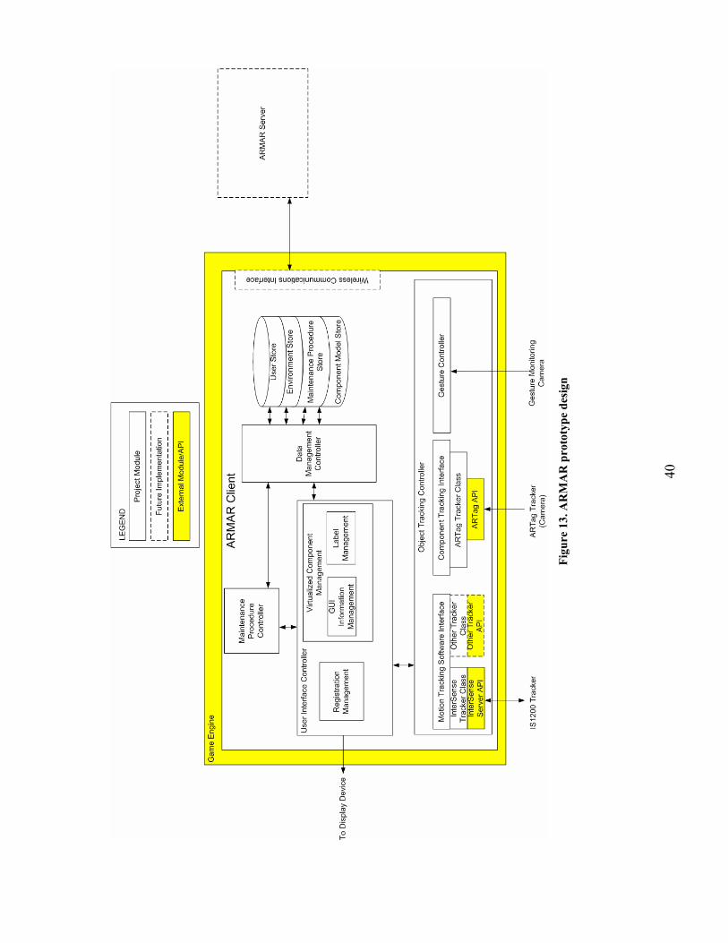
40
Fi
gure
13.
AR
MA
R p
roto
type
des
ign

41
4.1.2. Maintenance Procedure Controller
The Maintenance Procedure Controller encapsulates information and control logic
specific to the maintenance job aiding domain. This highly coupled component loads the current
repair task and related information, and then monitors the user’s overall progress through
specific repair steps. Additionally, this controller sets the overall repair context for the User
Interface Controller, allowing the application to filter virtual content to include only labels, GUI
objects, models, and user input relevant to the current repair task. The highly coupled nature of
this component permits developers to easily update and configure the ARMAR Client
application for specific repaired systems without altering the overall client design.
This controller includes functionality for designing, specifying, and editing the actual
content and control logic used in the application. This includes textual data and specialized
media (e.g., models, images, audio, and video) used to describe and augment the repair tasks and
maintenance environment. Additionally, the controller also provides functionality for describing
user interactions with the system.
The maintenance procedure controller also contains logic for configuring the ARMAR
client as a training application. The controller specifies which aspects of the application are
strictly virtual, augmented (virtual and real), or strictly real. This allows the application to
function either entirely as a virtual training tool or as a training tool used in a real maintenance
training environment (either operating entirely in support of training, or providing ancillary
training during actual maintenance tasks).
4.1.3. Object Tracking Controller
The Object Tracking Controller tracks the user and other objects. A Motion Tracking
Software Interface tracks the user, and leverages a third-party InterSense API to communicate
with a physical IS1200 hybrid tracker. This API, which we tested as part of our research, is
robust, stable and easy to integrate into custom designs.
The Component Tracking Interface provides tracking data for tools and other objects,
such as removed and replaced repair components. An ARTag Tracker Class, which tracks
markers attached to tools and repair components, provides the tracking data.

42
The Gesture Controller is responsible for recognizing and parsing user gestures used for
interacting with the application. This component provides the augmented control functionality
we developed during this project and detailed earlier in this report. A separate camera provides
the gesture tracking data.
4.1.4. Data Management Controller
The Data Management Controller acts as a data layer for the ARMAR Client and
interfaces with a single, unified data store that houses all information required by the application.
The data store contains information about the user, such as preferences, specific skill sets,
experience, and interaction history. The data store also features information about the
environment, such as lighting and location data. The data store holds domain specific data, such
as repair sequences, component labels, and warnings. Finally, the data store also contains the 3D
models required for registration and production of virtualized content.
4.2. ARMAR Server
Our design includes the concept of a centralized ARMAR Server. This server interfaces
through a wireless network to numerous ARMAR Clients and other applications. This facilitates
collaborative job aiding scenarios in which multiple ARMAR Clients operate in the same
physical space or as geographically separate units providing remote support. Additionally, the
server allows integration of other applications, such as purely virtual environments used for job
monitoring, historic review, or remote assistance. The server also provides remote data
management functions for updating or querying individual client data stores.

43
4.3. Prototype Demonstration: Removing the Oil Pressure
Transducer
In order to test the viability and software/hardware integration of our design, we
implemented a portion of the ARMAR Client as a prototype demonstration (Figure 14). At this
time, the demonstration’s implementation is limited to partially implemented user interface and
object management controllers. The entire design is built on top of the Valve Source game
engine SDK, receives tracking data from an InterSense IS1200 Beta hybrid inertial-optical
tracker, and renders stereoscopic content using an InnerOptic Vidsee video see-through HWD.
Figure 14. ARMAR prototype demonstration

44
Currently, the demonstration documents the removal of the Dart 510 oil pressure transducer,
and could be expanded to include additional maintenance tasks. Figure 15 shows an actual
screenshot of the application, as presented on the HWD. At the top of the screen, the application
presents the title of the overall repair task. Just below the title, the application displays the
current subtask (removing one of four retaining nuts). Virtual 3D labels and other indicators
pertaining to the tasks and subtask are overlaid in the center of the screen. At the bottom left
corner of the screen, a red and white label presents a warning. The bottom right hand corner
shows an iconified version of the main tool used for the current subtask. The background of the
screenshot is an image captured from one of the cameras in the HWD. (The actual application
uses two cameras to capture a stereo pair.)
Figure 15. ARMAR prototype demonstration screenshot

45
The prototype provides a bright and usable augmented view of the repair task. Rendering
performance averaged 30 frames per second (in stereo) on a computer with a 2.61 GHz dual core
AMD processor, 2 GB of RAM, and a NVIDIA Quadro 4500 FX2 graphics card. Video
capturing is accomplished by a Matrox Morphis capture card. Preliminary analysis of tracking,
with minimal effort applied to registration, revealed excellent update speeds, closely matched
virtual and real content, and minimal jitter.
Despite our limited implementation, these results were very helpful on several levels. First,
the demonstration allowed us to work through many software and hardware issues, such as
integrating the captured stereo pair and tracking data into Valve Source and rendering the game
engine’s DirectX-based content in stereo on the NVIDIA graphics card. Second, the results
validated the capabilities of our chosen software and hardware implementations. Third, the
demonstration enabled us to test several presentation and user-interface concepts (e.g. labeling
and instruction delivery). Finally, the availability of a compelling video see-through display
featuring high-resolution graphics and backed by fast and accurate tracking provides us with an
excellent environment for continued work in maintenance job-aiding and other domains.
4.4. Augmented Controls: A Prototype User Interaction Technique
In Section 3.3.5, we introduced a prototype user interface technique based on user
manipulation of augmented controls. The following series of photos shows a running example of
our proposed interaction technique. Figure 16 is a manually annotated digital photo that depicts
the primary elements of the interface area. A hex nut located to the far right of the repair area
(top of figure) serves as a start and select button. This augmented control activates the overlaid
menu and selects menu items. We chose the hex nut as the anchor for this augmented control,
because it affords many characteristics of a real button in appearance, size, and feel. Next to the
button are four louvered engine joints that serve as buttons for the menu items. We selected
these points because they naturally protrude from the engine and share the geometry and physical
width of the items displayed in the menu.

46
Start/Select Button(Hex Nut)
Menu Buttons(Louvers)
Repair Area(Transducer)
Figure 16. Augmented controls interface area
Figures 17–20 show the user activating the overlaid window, loading the first step, and
iterating over the task steps. These captured screen shots are individual 800×600 pixel frames
rendered in the stereoscopic video see-through display, and do not include virtual overlays for
the augmented controls.

47
Figure 17. User activates repair menu

48
Figure 18. User selects repair procedure

49
Figure 19. System loads first step and hides menu

50
Figure 20. User cues for next step
Our implementation uses a single web camera, mounted on a stationary pedestal, which
captures images from the interface area at 30 frames per second. These images are then analyzed
by a computer-vision–based gesture-parsing algorithm implemented in three phases: data
reduction, gesture matching, and gesture parsing.
In the data reduction phase, we segment each color image from the camera into a sparse
binary version. Because our application is primarily interested in detecting the user’s hand, we
adapted a segmentation algorithm used by Kjeldsen [26] that filters for significant values of the
primary color red in the source image’s 24-bit RGB color format. This algorithm capitalizes on
the high levels of red that naturally reflect from human skin. When coupled with a controlled
lighting environment (one limited in naturally occurring red light), this filtering can effectively
isolate a user’s hand from other objects in an image. In our implementation, we conducted
statistical analysis of several sampled images, with and without gestures, to establish the
following filter:

51
∈
=else
rifbgrf
0]255,120[1
),,( ,
where r, g, b correspond to red, green, and blue luminance values stored as bytes in the original
image. Figure 21 depicts an example binary image segmented when we apply our filter to a
source image captured with our application.
Figure 21. Example binary image
As portrayed in the example figure, the binary image results in groupings of pixels (one large
grouping with several smaller groupings) called connected components. Our algorithm
recursively and quickly scans the binary image (now containing roughly 5% of the original
number of pixels in the color image) for these connected components, then selects the largest
component as the user’s hand.
The next phase of our algorithm, gesture matching, calculates the location of the pixel ph in
the hand’s corresponding connected component C, where:

52
Cpyyyxp
componentinpixelsnipC
iih
hhh
i
∈∀≤=
==),(
..1,.
The algorithm then attempts to match this pixel, which represents the “highest” hand
generated pixel in the original image, to the physical coordinates of the various augmented
control interface points. In order to facilitate this matching, our algorithm must transform ph,
which is measured in camera coordinates, to interface coordinates. To accomplish this
transformation, we use Kjeldsen’s approach [26] to calculate the transformation matrix Â, where:
TAA 1ˆ −= ,
=
333231
232221
131211
aaaaaaaaa
A ,
21
21
23
23
13
yyxxyyxx
a
∆∆∆∆∆∆∆∆
=
21
21
31
31
23
yyxxyyxx
a
∆∆∆∆∆∆∆∆
= ,
(x0, y0) = upper left corner of interface area (camera coordinates),
(x1, y1) = upper right corner of interface area (camera coordinates),
(x2, y2) = lower right corner of interface area (camera coordinates),
(x3, y3) = lower left corner of interface area (camera coordinates),
32103
232
211
32103
232
211
yyyyyyyyyyy
xxxxxxxxxxx
−+−=∆−=∆−=∆
−+−=∆−=∆−=∆
,

53
032
3230322
1130112
031
3230321
1130111
ya
yayyayayya
xa
xaxxaxaxxa
=
+−=+−=
=
+−=+−=
,
=
1000000
hw
T ,
w = width of interface area (in interface coordinates), and
h = height of interface area (in interface coordinates).
Our algorithm uses the resultant transformation matrix Â, and the following set of equations,
to calculate the interface coordinates for the highest pixel in the hand’s connected component:
332313
322212
332313
312111
ˆˆˆˆˆˆ
ˆˆˆˆˆˆ
,,
,,
AyAxAAyAxAy
AyAxAAyAxAx
phandinpixelhighestofcoordinateyCamerayphandinpixelhighestofcoordinatexCamerax
phandinpixelhighestofcoordinateyInterfaceyphandinpixelhighestofcoordinatexInterfacex
hh
hhm
hh
hhm
mh
mh
mm
mm
++++
=
++++
=
==
==
The algorithm then matches the translated interface point (xm , ym), now in interface
coordinates, to physically measured 2D polygon regions representing the augmented control
points in the interface. If the translated coordinates fall within one of the polygons, the
algorithm classifies the hand’s connected component as a particular gesture. Figure 22 shows a
table of interface coordinates to gesture mappings used in our application.

54
All units in centimeters
Figure 22. Mapping interface coordinates to gestures
The final phase of the algorithm, gesture parsing, tracks the current state of the interface, and
transitions to new states based on incoming gestures. We accomplish this by implementing a
finite state machine (Figure 23). At any particular instance during use of the interface, this state
machine resides in one of seventeen states, and transitions to new states based on incoming
gestures. These states and transitions are briefly described below:
START STATE. The start state for the system. All menus are hidden. The repair text
(instructions for the user about the particular maintenance step to perform in a repair) is hidden.
SHOW REPAIR SELECTION MENU. The user selected the Repair Selection Menu by
gesturing on the interface button (B00). The Repair Selection Menu is displayed on the screen.
HIDE SELECT MENU. The user selected the “Hide Menu” menu item in the Repair
Selection Menu (W00).
SELECT REPAIR1. The user selected the first repair in the Repair Selection Menu (W01).

55
SELECT REPAIR2. The user selected the second repair in the Repair Selection Menu
(W02).
LOAD REPAIR1. The user selected the interface button (B00) while the first repair was
selected. The system loads the repair’s first step in the display, and hides the Repair Selection
Menu.
LOAD REPAIR2. The user selected the interface button (B00) while the second repair was
selected. The system loads the repair’s first step in the display, and hides the Repair Selection
Menu.
SHOW SUB MENU. The user selected the Repair Submenu with the interface button (B00)
while an active repair is underway. The system displays the Repair Submenu.
SELECT HIDE SUB MENU. The user selected the “Hide Menu” menu item in the Repair
Submenu (W00).
SELECT NEXT STEP. The user selected the “Next Step” menu item in the Repair
Submenu (W01).
CONTINUE REPAIR. The user selected the interface button (B00) while the “Hide Menu”
item in the Repair Submenu is selected. The state simply hides the Repair Submenu. The system
reached this state as an intermediate internal transition.
SELECT STOP REPAIR. The user selected the “Stop Repair” menu item in the Repair
Submenu (W01).
SELECT EXIT. The user selected the “Exit” menu item in the Repair Submenu (W01).
56
LOAD NEXT STEP. The user selected the interface button (B00) while the “Next Step”
menu item in the Repair Submenu is selected. The state loads the next step for the current repair
(if applicable). The text describing the next step is displayed in the interface and the system hides
the Repair Submenu. The system then transitions to the CONTINUE REPAIR state.
STOP REPAIR. The user selected the interface button (B00) while the “Stop Repair” menu
item in the Repair Submenu is selected. The system removes any text in the interface’s display
and hides the Repair Submenu.
EXIT. The user selected the interface button (B00) while the “Exit” menu item in the Repair
Submenu is selected. The system issues a call to close the application.
DONE WITH REPAIR. This intermediate step is reached if the last step in a repair
sequence is reached following a LOAD NEXT STEP state. The system adds a “Repair
Completed” message to the display and hides all menus.
System performance is highly resistant to errors in gestures because the physical control
point naturally restricts and canalizes the user’s gesture. A disadvantage of our implementation
is the susceptibility of the vision algorithm to lighting conditions. This could be addressed in
future implementations by leveraging more robust vision algorithms or by using fiducials.

57
Fi
gure
23.
Aug
men
ted
cont
rols
stat
e di
agra
m

58
We believe this augmented control interaction technique is viable for the maintenance job
aiding task for several reasons. First, with minimal practice, a user can learn to negotiate the
nearby augmented controls while keeping their eyes focused on the repair area. Second, because
the controls are within arm’s reach, a user can minimize the time needed to activate the controls
and return their hands to the repair area. Third, we believe it is possible to identify sets of
physical component/ augmented control heuristics that apply across a wide variety of mechanical
features; for example, “all washers are wheels” or “the largest outboard hex nut is the activation
button.” We also feel we can improve our preliminary implementation of the technique by
converting the 2D text currently displayed in the translucent windows to 3D text rendered at key
locations in the environment (e.g., on surfaces near the repair). This would prevent 2D artifacts
from occluding the user’s view of the repair area. Finally, as suggested by Hoffman, physically
touching virtual objects with tangible feedback enhances realism in the augmented environment
[23].

59
5. References [1] D. F. Abawi, J. Bienwald, and R. Dorner, "Accuracy in Optical Tracking with Fiducial
Markers: An Accuracy Function for ARToolKit," Proceedings of the Third IEEE and ACM International Symposium on Mixed and Augmented Reality (ISMAR '04), Arlington, VA, 2004, pp. 260-261.
[2] R. Azuma, Y. Baillot, R. Behringer, S. Feiner, S. Julier, and B. MacIntyre, "Recent Advances in Augmented Reality," IEEE Computer Graphics and Applications, 21(6), 2001. pp. 34-47.
[3] R. T. Azuma, "A Survey of Augmented Reality," Presence: Teleoperators and Virtual Environments, 6(4), 1997. pp. 355-385.
[4] M. Bajura, H. Fuchs, and R. Ohbuchi, "Merging Virtual Objects with the Real World: Seeing Ultrasound Imagery within the Patient," SIGGRAPH Computer Graphics 26(2), 1992. pp. 203-210.
[5] B. Bell, S. Feiner, and T. Höllerer, "View Management for Virtual and Augmented Reality," Proceedings of the 14th annual ACM symposium on User interface software and technology, 2001. pp. 101-110.
[6] O. Bimber and R. Raskar, Spatial Augmented Reality: Merging Real and Virtual Worlds. 2005: A. K. Peters, Ltd.
[7] G. Bleser, Y. Pastarmov, and D. Stricker, "Real-time 3D Camera Tracking for Industrial Augmented Reality Applications," International Conference in Central Europe on Computer Graphics, Visualization and Computer Vision, Plzen - Bory, Czech Republic, 2005, pp. 47-54.
[8] A. C. Boud, D. J. Haniff, C. Baber, and S. J. Steiner, "Virtual Reality and Augmented Reality as a Training Tool for Assembly Tasks," Proceedings of the IEEE International Conference on Information Visualization, 1999, pp. 32-36.
[9] P. Boulanger, "Application of Augmented Reality to Industrial Tele-Training," Proceedings of the First Canadian Conference on Computer and Robot Vision (CRV'04) Ontario, 2004, pp. 320-328.
[10] A. M. Bruckstein, R. J. Holt, T. S. Huang, and A. N. Netravali, "New Devices for 3D Pose Estimation: Mantis Eyes, Agam Paintings, Sundials, and Other Space Fiducials," ICPR, 1998, pp. 305-309.
[11] T. P. Caudell and D. W. Mizell, "Augmented Reality: An Application of Heads-up Display Technology to Manual Manufacturing Processes," Proceedings of the Twenty-Fifth International Conference on System Sciences, Hawaii, 1992, pp. 659-669 vol.2.

60
[12] E. M. Coelho, S. J. Julier, and B. Maclntyre, "OSGAR: A Scene Graph with Uncertain Transformations," Proceedings of the Third IEEE and ACM International Symposium on Mixed and Augmented Reality (ISMAR '04), Arlington, VA, 2004, pp. 6-15.
[13] A. Comport, E. Marchand, M. Pressigout, and F. Chaumette, "Real-Time Markerless Tracking for Augmented Reality: The Virtual Visual Servoing Framework," IEEE Transactions on Visualization and Computer Graphics, 12(4), 2006. pp. 615-628.
[14] B. D. Conner, S. S. Snibbe, K. P. Herndon, D. C. Robbins, R. C. Zeleznik, and A. van Dam, "Three-Dimensional Widgets," Proceedings of the 1992 Symposium on Interactive 3D Graphics, Cambridge, Massachusetts, 1992, pp. 183-188.
[15] S. Feiner, B. Macintyre, and D. Seligmann, "Knowledge-based Augmented Reality," Communications of the ACM, 36(7), 1993. pp. 53-62.
[16] M. L. Fiala, "ARTag, a Fiducial Marker System Using Digital Techniques," Proceedings of the 2005 IEEE Computer Society Conference on Computer Vision and Pattern Recognition (CVPR'05) - Volume 2, Washington, DC, 2005, pp. 590-596.
[17] E. Foxlin and L. Naimark, "VIS-Tracker: A Wearable Vision-Inertial Self-Tracker," Proceedings of the IEEE Conference on Virtual Reality (VR '03), Washington, DC, 2003, p. 199.
[18] W. Friedrich, "ARVIKA-Augmented Reality for Development, Production and Service," Proceedings of the International Symposium on Mixed and Augmented Reality (ISMAR'02), Washington, DC, 2002, pp. 3-4.
[19] S. Goose, S. Güven, X. Zhang, S. Sudarsky, and N. Navab, "PARIS: Fusing Vision-based Location Tracking with Standards-based 3D Visualization and Speech Interaction on a PDA," Proceedings of the IEEE International Conference on Distributed Multimedia Systems (DMS '04), San Francisco, CA, 2004, pp. 75-80.
[20] P. Grimm, M. Haller, V. Paelke, S. Reinhold, C. Reimann, and R. Zauner, "AMIRE - Authoring Mixed Reality," The First IEEE International Workshop on Augmented Reality Toolkit, 2002, p. 2.
[21] S. Güven and S. Feiner, "Authoring 3D Hypermedia for Wearable Augmented and Virtual Reality," Proceedings of the Seventh IEEE International Symposium on Wearable Computers, White Plains, NY, 2003, pp. 118-126.
[22] M. Haringer and H. T. Regenbrecht, "A Pragmatic Approach to Augmented Reality Authoring," Proceedings of the International Symposium on Mixed and Augmented Reality (ISMAR'02), Washington, DC, 2002.
[23] H. G. Hoffman, "Physically Touching Virtual Objects using Tactile Augmentation Enhances the Realism of Virtual Environments," Proceedings of the IEEE Virtual Reality Annual International Symposium, Atlanta, GA, 1998, pp. 59-63.

61
[24] H. Kato and M. Billinghurst, "Marker Tracking and HMD Calibration for a Video-Based Augmented Reality Conferencing System," Proceedings of the 2nd IEEE and ACM International Workshop on Augmented Reality, 1999, p. 85.
[25] K. Kiyokawa, M. Billinghurst, B. Campbell, and E. Woods, "An Occlusion-Capable Optical See-through Head Mount Display for Supporting Co-located Collaboration," Proceedings of the The 2nd IEEE and ACM International Symposium on Mixed and Augmented Reality (ISMAR '03), Tokyo, 2003.
[26] F. Kjeldsen, Visual Interpretation of Hand Gestures as a Practical Interface Modality. 1997, Columbia University.
[27] C. Knopfle, J. Weidenhausen, L. Chauvigne, and I. Stock, "Template Based Authoring for AR Based Service Scenarios," Proceedings of the 2005 IEEE Conference on Virtual Reality (VR '05), 2005, pp. 249-252.
[28] J. R. Lewis, "In the Eye of the Beholder [displays]," IEEE Spectrum, 41(5), 2004. pp. 24-28.
[29] P. Milgram, H. Takemura, A. Utsumi, and F. Kishino, "Augmented Reality: A Class of Displays on the Reality-Virtuality Continuum," Proceedings of Telemanipulator and Telepresence Technologies, 1994, pp. 282-292.
[30] D. Mizell, "Boeing's Wire Bundle Assembly Project," in Fundamentals of Wearable Computers and Augmented Reality, W. Barfield and T. Caudell, Editors. 2001, Lawrence Erlbaum and Associates. pp. 447-467.
[31] A. Mulder, Human Movement Tracking Technology, Technical Report 94-1, School of Kinesiology, Simon Fraser University, Burnaby, B.C., Canada, 1994.
[32] J. Platonov, H. Heibel, P. Meier, and B. Grollmann, "A Mobile Markerless AR System for Maintenance and Repair," Fifth IEEE and ACM International Symposium on Mixed and Augmented Reality (ISMAR '06), Santa Barbara, CA, 2006, pp. 105-108.
[33] S. G. Rao, S. J. Schmugge, and L. F. Hodges, "Vision-based System for Head Pose Tracking in Indoor Immersive Environments," Proceedings of the 14th International Conference on Artificial Reality and Telexistence (ICAT2004), 2004.
[34] H. Regenbrecht, G. Baratoff, and W. Wilke, "Augmented Reality Projects in the Automotive and Aerospace Industries," IEEE Computer Graphics and Applications, 25(6), 2005. pp. 48-56.
[35] J. Rekimoto, "The Magnifying Glass Approach to Augmented Reality Systems," International Conference on Artificial Reality and Tele-Existence / Conference on Virtual Reality Software and Technology (ICAT/VRST'95), Makuhari, Japan, 1995, pp. 123-132.
[36] J. P. Rolland, L. D. Davis, and Y. Baillot, "A Survey of Tracking Technologies for Virtual Environments," in Fundamentals of Wearable Computers and Augmented Reality,

62
W. Barfield and T. Caudell, Editors. 2001, Lawerence Erlbaum: Mahwah, NJ. pp. 67-112.
[37] E. Rose, D. Breen, K. H. Ahlers, C. Crampton, M. Tuceryan, R. Whitaker, and D. Greer, Annotating Real-world Objects using Augmented Reality, in Computer Graphics: Developments in Virtual Environments. 1995, Academic Press Ltd. . p. 357-370.
[38] H. Slay, B. Thomas, and R. Vernik, "Tangible User Interaction Using Augmented Reality," Australasian Conference on User interfaces, Melbourne, Australia, 2002, pp. 13-20.
[39] A. State, K. P. Keller, and H. Fuchs, "Simulation-based Design and Rapid Prototyping of a Parallax-free, Orthoscopic Video See-through Head-mounted Display," Proceedings of the Fourth IEEE and ACM International Symposium on Mixed and Augmented Reality (ISMAR '05), Vienna, Austria, 2005, pp. 28-31.
[40] I. E. Sutherland, "A Head-mounted Three Dimensional Display," Proceedings of the AFIPS Fall Joint Computer Conference, 1968, pp. 757-764.
[41] A. Tang, C. Owen, F. Biocca, and W. Mou, "Comparative Effectiveness of Augmented Reality in Object Assembly," Proceedings of the SIGCHI conference on Human Factors in Computing Systems, Ft. Lauderdale, FL, 2003, pp. 73-80.
[42] A. Webster, S. Feiner, B. Maclntyre, B. Massie, and T. Krueger, "Augmented reality in Architectural Construction, Inspection and Renovation," ASCE Third Congress on Computing in Civil Engineering, Anaheim, CA, 1996.
[43] A. L. Young, A. W. Stedman, and C. A. Cook, "The Potential of Augmented Reality Technology for Training Support Systems," Proceedings of the International Conference on Human Interfaces in Control Rooms, Cockpits and Command Centres, 1999, pp. 242-246.
[44] J. Zauner, M. Haller, A. Brandl, and W. Hartman, "Authoring of a Mixed Reality Assembly Instructor for Hierarchical Structures," Proceedings of the Second IEEE and ACM International Symposium on Mixed and Augmented Reality (ISMAR '03), Tokyo, 2003, pp. 237-246.
[45] ARTESAS - Advanced Augmented Reality Technologies for Industrial Service Applications, http://www.artesas.de.
[46] Irrlicht Open Source Gaming Engine, http://irrlicht.sourceforge.net/.
[47] OpenSceneGraph, http://www.openscenegraph.org/.
[48] Valve Source Engine Software Development Kit, http://developer.valvesoftware.com.


![State of Augmented Reality, Virtual Reality and Mixed Reality · State of Augmented Reality, Virtual Reality and Mixed Reality [Microsoft Hololen] [Ready Player One] Augmented Reality](https://static.fdocuments.net/doc/165x107/5f82ab6da2d89130b90d78c7/state-of-augmented-reality-virtual-reality-and-mixed-reality-state-of-augmented.jpg)