ASE 6 - Electrical Electronic...
29
ASE 6 - Electrical Electronic Systems Module 16 Lighting Systems
Transcript of ASE 6 - Electrical Electronic...

ASE 6 - Electrical ElectronicSystems
Module 16Lighting Systems

AcknowledgementsGeneral Motors, the IAGMASEP Association Board of Directors, and RaytheonProfessional Services, GM's training partner for GM's Service Technical College wish tothank all of the people who contributed to the GM ASEP/BSEP curriculum developmentproject 2002-3. This project would not have been possible without the tireless efforts ofmany people. We acknowledge:
• The IAGMASEP Association members for agreeing to tackle this large project tocreate the curriculum for the GM ASEP/BSEP schools.
• The IAGMASEP Curriculum team for leading the members to a single vision andimplementation.
• Direct contributors within Raytheon Professional Services for their support oftranslating a good idea into reality. Specifically, we thank:
– Chris Mason and Vince Williams, for their leadership, guidance, and support.– Media and Graphics department under Mary McClain and in particular, Cheryl
Squicciarini, Diana Pajewski, Lesley McCowey, Jeremy Pawelek, & NancyDeSantis.
– For his help on the Electrical curriculum volume, Subject Matter Expert, KenBeish, Jr., for his wealth of knowledge.
Finally, we wish to recognize the individual instructors and staffs of the GM ASEP/BSEPColleges for their contribution for reformatting existing General Motors training material,adding critical technical content and the sharing of their expertise in the GM product.Separate committees worked on each of the eight curriculum areas. For the work on thisvolume, we thank the members of the Electrical committee:
– Jack Davis, Community College of Baltimore County - Catonsville– Jim Halderman, Sinclair Community College– Megan Kuehm, Community College of Allegheny County– Frank Longbottom, Camden County College– Jeff Rehkopf, Florida Community College at Jacksonville– Randy Peters, Des Moines Area Community College– David Rodriguez, College of Southern Idaho– Ed Schauffler, Longview Community College– Vince Williams, Raytheon

ContentsModule 16 – Lighting SystemsAcknowledgements .......................................................................................... 2Introduction ...................................................................................................... 4Objectives ........................................................................................................ 4
Lesson 1. Headlamp/Daytime Running Lamp (DRL) ...................................................... 5Lesson 2. Headlamp/Daytime Running Lamp (DRL) ...................................................... 7Labsheet 1: Headlamps ................................................................................................ 15Lesson 3: Exterior Lights .............................................................................................. 18Labsheet 2: Turn Lamps ............................................................................................... 23Lesson 4: Interior Lamps .............................................................................................. 24Lesson 5: Interior Lamps Dimming ............................................................................... 28

© 2002 General Motors CorporationAll Rights Reserved
ASE 6 - ElectricalElectronic Systems
Module 16 -Lighting Systems
16-4
Student WorkbookIntroductionLesson 1: Daytime Running LampsLesson 2: HeadlampsLesson 3: External LampsLesson 4: Dome and Interior LampsLesson 5: Interior Lamps DimmingLabsheet 1: Headlamps/Daytime Running LampsLabsheet 2: Turn Lamps
ObjectivesNATEF Tasks:Area VI. E. Lighting System Diagnosis and Repair1. Diagnose the cause of brighter than normal, dim, or no light operation;
determine necessary action.2. Inspect, replace and aim headlights and bulbs.3. Inspect and diagnose incorrect turn signal or hazard light operation;
perform necessary action.Headlamp/Daytime Running Lamp Lab Objectives:• identify types of headlamp controls• use service information to locate, remove and replace components• read electrical schematics• make measurements with DVOM• use a Tech 2 to monitor and operate inputs and outputs• aim headlamps with headlamp aimerExterior Lamp Lab Objectives:• identify types of turn lamp controls• use service information to locate, remove, and replace components• read electrical schematics• make measurements with a DVOM

© 2002 General Motors CorporationAll Rights Reserved
ASE 6 - ElectricalElectronic Systems
Module 16 -Lighting Systems
16-5
Student WorkbookLesson 1. Headlamp/Daytime Running Lamp (DRL)
The headlamp/DRL circuit contain the following main components:• Right and left headlamps• Multifunction turn signal switch• Daytime running lamp (DRL) relay• Body control module (BCM)

© 2002 General Motors CorporationAll Rights Reserved
ASE 6 - ElectricalElectronic Systems
Module 16 -Lighting Systems
16-6
Student WorkbookHeadlampsThe headlamps are operated when the driver places the headlamp switchin the HEADLAMP position. The LT HDLP and RT HDLP fuse in the IPfuse block, supply battery positive voltage to both the left and rightheadlamps. The low beam and high beam circuits continue to theheadlamp switch. Depending on the position of the dimmer switch, eitherthe low or high beam circuit will now have a path to ground. Ground isprovided at G102. The low beam and high beam circuits also provide thebody control module (BCM) with both low and high beam inputs. When theBCM senses high beam selection, a class 2 message is sent to theinstrument panel cluster (IPC). The IPC then turns on the high beamindicator lamp. The headlamp switch includes the dimmer and the flash-to-pass switch.If the headlight switch is left in the HEADLAMP position, the headlights willremain on until turned off or the battery runs dead.
Daytime Running Lamps (DRL)Any function that turns on the headlights will cancel the daytime runninglamps operation. The LT HDLP fuse in the IP fuse block supplies batterypositive voltage to the daytime running lamp (DRL) relay coil circuit. TheDRL relay switch contacts are connected to the low beam circuit. Whenthe headlamp switch is placed in the OFF position, the BCM will turn onthe daytime running lamps. The BCM energizes the DRL relay, closing theswitch contacts and grounding the low beam circuit at G204. The right andleft low beam lamps are now in series as are the right and left hi beamlamps. One half of system voltage is dropped across each lamp. The DRLilluminate the low and high beam headlights at a reduced intensity. TheDRL will operate when the ignition switch is in the RUN position, the gearselector is not in the PARK position and the parking brake is released.When these conditions have been met the DRL will illuminate.DRL operation in Manual Transmission equipped vehicles will occur whenthe ignition switch is in the RUN position, and the parking brake isreleased.

© 2002 General Motors CorporationAll Rights Reserved
ASE 6 - ElectricalElectronic Systems
Module 16 -Lighting Systems
16-7
Student WorkbookLesson 2. Headlamp/Daytime Running Lamp (DRL)
The main components in the headlights/daytime running lights are:• The high beam lamps• The low beam lamps• The headlight switch• The headlight relay• The headlamp dimmer switch• The ambient light sensor• The body control module (BCM)• The front turn signal lamps (DRL operation)
HeadlampsThe headlamps may be turned on two different ways:• When the driver places the headlamp switch in the ON position, for
normal operation.• With the headlamp switch placed in the OFF position, during Daytime
Running Lamp (DRL) operation in low light conditions, for automaticoperation.

© 2002 General Motors CorporationAll Rights Reserved
ASE 6 - ElectricalElectronic Systems
Module 16 -Lighting Systems
16-8
Student Workbook
The HDLP L and HDLP R fuse in the underhood accessory wiring junctionblock supply battery positive voltage to both low beam lamps and highbeam lamps at all times. The low beam and high beam circuits continue tothe headlamp dimmer switch. The low beam or high beam circuit is then,depending on the position of the dimmer switch, connected to theheadlamp switch.
© 2002 General Motors CorporationAll Rights Reserved
ASE 6 - ElectricalElectronic Systems
Module 16 -Lighting Systems
16-9
Student Workbook
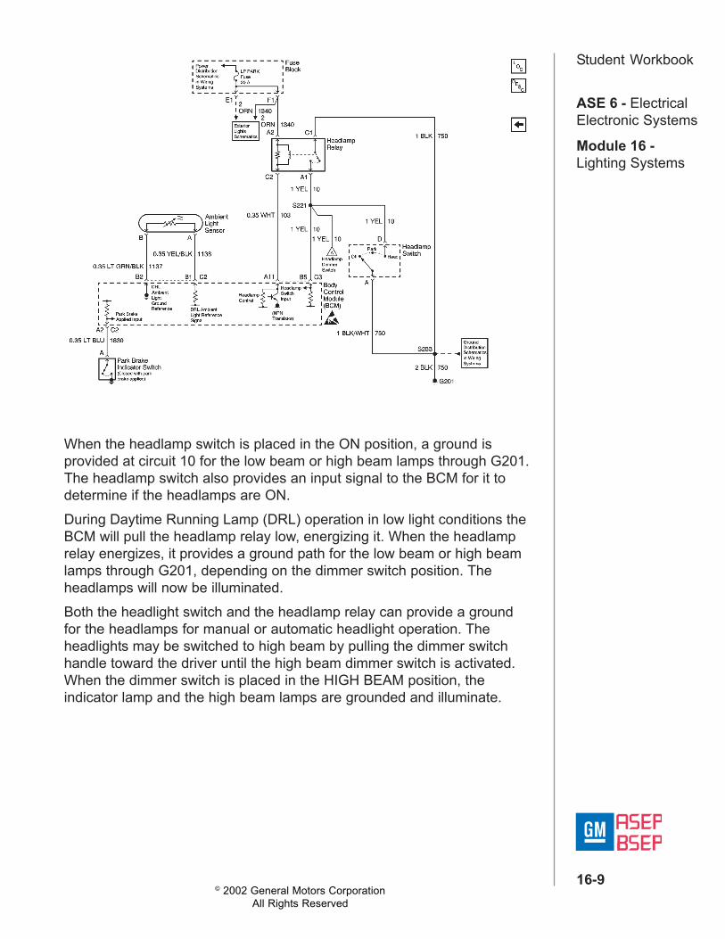
When the headlamp switch is placed in the ON position, a ground isprovided at circuit 10 for the low beam or high beam lamps through G201.The headlamp switch also provides an input signal to the BCM for it todetermine if the headlamps are ON.During Daytime Running Lamp (DRL) operation in low light conditions theBCM will pull the headlamp relay low, energizing it. When the headlamprelay energizes, it provides a ground path for the low beam or high beamlamps through G201, depending on the dimmer switch position. Theheadlamps will now be illuminated.Both the headlight switch and the headlamp relay can provide a groundfor the headlamps for manual or automatic headlight operation. Theheadlights may be switched to high beam by pulling the dimmer switchhandle toward the driver until the high beam dimmer switch is activated.When the dimmer switch is placed in the HIGH BEAM position, theindicator lamp and the high beam lamps are grounded and illuminate.

© 2002 General Motors CorporationAll Rights Reserved
ASE 6 - ElectricalElectronic Systems
Module 16 -Lighting Systems
16-10
Student WorkbookFlash to PassThe flash to pass feature can be operated with the low beams OFF or ON.The high beams may be momentarily turned on or flashed with thedimmer switch handle. When the headlamp dimmer switch handle ispulled toward the driver, the flash-to-pass switch closes grounding thehigh beam circuit at G201, both high beams will remain on until the driverreleases the switch handle. If the low beam headlamps were on during aflash-to-pass operation, they will remain on.
Daytime Running Lamps (DRL)The Daytime Running Lamps (DRL) are designed to automatically operateexterior lights depending on outside light conditions.
The ambient light sensor is a light sensitive transistor that varies itsvoltage signal to the body control module (BCM) in response to changesto the outside (ambient) light level. When the BCM receives this signal itwill then operate the DRL in either day mode or low light mode dependingon the light level.

© 2002 General Motors CorporationAll Rights Reserved
ASE 6 - ElectricalElectronic Systems
Module 16 -Lighting Systems
16-11
Student Workbook
In the day mode, the ambient light sensor detects daylight and the BCMapplies voltage from circuit 439 to the LH and RH front turn signal lampscircuits 14 and 15.
Day Mode

© 2002 General Motors CorporationAll Rights Reserved
ASE 6 - ElectricalElectronic Systems
Module 16 -Lighting Systems
16-12
Student Workbook
These turn signal lamps are used for DRL illumination under the followingconditions:• The ignition switch is in the RUN position.• The headlamps are OFF.• The park brake is OFF (released).• The RH or LH turn signal is OFF.

© 2002 General Motors CorporationAll Rights Reserved
ASE 6 - ElectricalElectronic Systems
Module 16 -Lighting Systems
16-13
Student Workbook
The Low Light ModeIn the low light mode, the ambient light sensor detects low light level, theBCM turns OFF the front turn signal lamps and grounds the park lamprelay circuit 308 and headlamp relay circuit 103. Circuit 10 is grounded bythe headlamp relay and the park lamp relay provides voltage to the 10amp front park fuse and the 15 amp tail and license lamp fuse. Circuit 9and 301 provide voltage to turn ON the headlamps and park lamps underthe following conditions:• The ignition switch is in the RUN position.• The headlamps are OFF.• The park brake is OFF (released).If the engine stalls with the DRL in the low light mode, the BCM turns OFFthe headlamps while the engine is being cranked. The park lamps willremain ON while the engine is being cranked.

© 2002 General Motors CorporationAll Rights Reserved
ASE 6 - ElectricalElectronic Systems
Module 16 -Lighting Systems
16-14
Student WorkbookDelayed Headlamp ControlThe BCM has a delayed headlamp control feature that will leave theheadlamps ON for 90 seconds after the ignition switch is turned OFF,when the ambient light sensor indicates low light conditions.
Park Brake InputThe BCM will not operate any headlamps or exterior lamps, if the parkbrake is applied before the ignition switch is turned to the RUN position.This allows the driver to start the vehicle and keep the headlamps OFF, aslong as the park brake is applied. The BCM will activate the headlampswhen the park brake is released with the ignition switch in the RUNposition. This feature functions only when the park brake is applied beforethe ignition switch is turned to the RUN position. The headlamps will turnOFF, if the park brake is applied after the ignition switch is turned to theRUN position.

© 2002 General Motors CorporationAll Rights Reserved
ASE 6 - ElectricalElectronic Systems
Module 16 -Lighting Systems
16-15
Student WorkbookLabsheet 1: HeadlampsLab Objectives:• identify types of headlamp controls• use service information to locate, remove and replace components• read electrical schematics• make measurements with DVOM• use a Tech 2 to monitor and operate inputs and outputs• aim headlamps with headlamp aimer
1. Locate a vehicle with daytime running lights. Visually inspect the bulbs.Are they are single or double filament/?_______________________________________________________
2. Indicate vehicle make, model, year. _________________________________________________________________________________
3. List the modules and relays used in the operation of the headlampsand DRL.______________________________________________________________________________________________________________
4. What lamps are illuminated for DRL day mode?______________________________________________________________________________________________________________
5. Are these lamps operated at reduced intensity?If so, what method is used to reduce the current flow of these lamps?______________________________________________________________________________________________________________
6. What type of light sensor is used.____________________________________________________________________________________________________________

© 2002 General Motors CorporationAll Rights Reserved
ASE 6 - ElectricalElectronic Systems
Module 16 -Lighting Systems
16-16
Student Workbook7. Backprobe the signal side of the light sensor with a voltmeter andmeasure the voltage with a shop light applied to the sensor. Measurethe voltage with the sensor covered.______________________________________________________________________________________________________________
8. List each module input provided by the headlamp switch and indicatethe type of input (switched power, ground, etc.)______________________________________________________________________________________________________________
9. List the headlamp switch inputs that can be displayed by a Tech 2.____________________________________________________________________________________________________________
10.Use a Tech 2 to check the on-off status of each of these inputs andrecord the results.____________________________________________________________________________________________________________
11. List each module input provided by the high-low beam switch andindicate the type of input (switched power, ground, etc.).__________________________________________________________________________________________________________
12.List the high-low beam switch inputs that can be displayed by aTech 2.____________________________________________________________________________________________________________
13.Use a Tech 2 to check the on-off status of each of these inputs andrecord the results. _______________________________________

© 2002 General Motors CorporationAll Rights Reserved
ASE 6 - ElectricalElectronic Systems
Module 16 -Lighting Systems
16-17
Student Workbook14.List all module controlled relays used in the headlamp circuit.______________________________________________________________________________________________________________
15.List the module controlled relays that can be controlled by the Tech 2.____________________________________________________________________________________________________________
16.Use a Tech 2 to turn on and off each of these relays and indicate theresults.____________________________________________________________________________________________________________
17.Perform the Diagnostic System Check for this system and list anyitems that did not pass.____________________________________________________________________________________________________________
18.List any recommended repairs.____________________________________________________________________________________________________________
19.Use a J 25300-A or equivalent to demonstrate the procedure to aimthe headlamps.____________________________________________________________________________________________________________
20.Review this worksheet with your instructor before leaving the vehicle.____________________________________________________________________________________________________________

© 2002 General Motors CorporationAll Rights Reserved
ASE 6 - ElectricalElectronic Systems
Module 16 -Lighting Systems
16-18
Student WorkbookLesson 3: Exterior LightsThe exterior light circuit main components are:• The headlamp switch• The park lamp relay• The body control module (BCM)• The turn signal switch• The turn/hazard flasher• The stop lamp switch• The front park lamps• The rear park lamps (tail lamps)• The front turn signal lamps• The rear turn signal lamps• The center high mounted stop lamp (CHIMSL)• The license lamp
Park and License LampsThe park and license lamps are controlled by the headlamp switch or thepark lamp relay in the RH IP Accessory Wiring Junction Block.

© 2002 General Motors CorporationAll Rights Reserved
ASE 6 - ElectricalElectronic Systems
Module 16 -Lighting Systems
16-19
Student Workbook
The park lamps and license lamps receive ground at all times.
When the headlamp switch is turned to the park position B+ is suppliedthrough the headlamp switch to both the tail lamp, license lamp fuse andthe front park lamp fuse. B+ is then applied through the park lamps circuitto the front and rear park lamps and the license lamps turning them on.
© 2002 General Motors CorporationAll Rights Reserved
ASE 6 - ElectricalElectronic Systems
Module 16 -Lighting Systems
16-20
Student Workbook
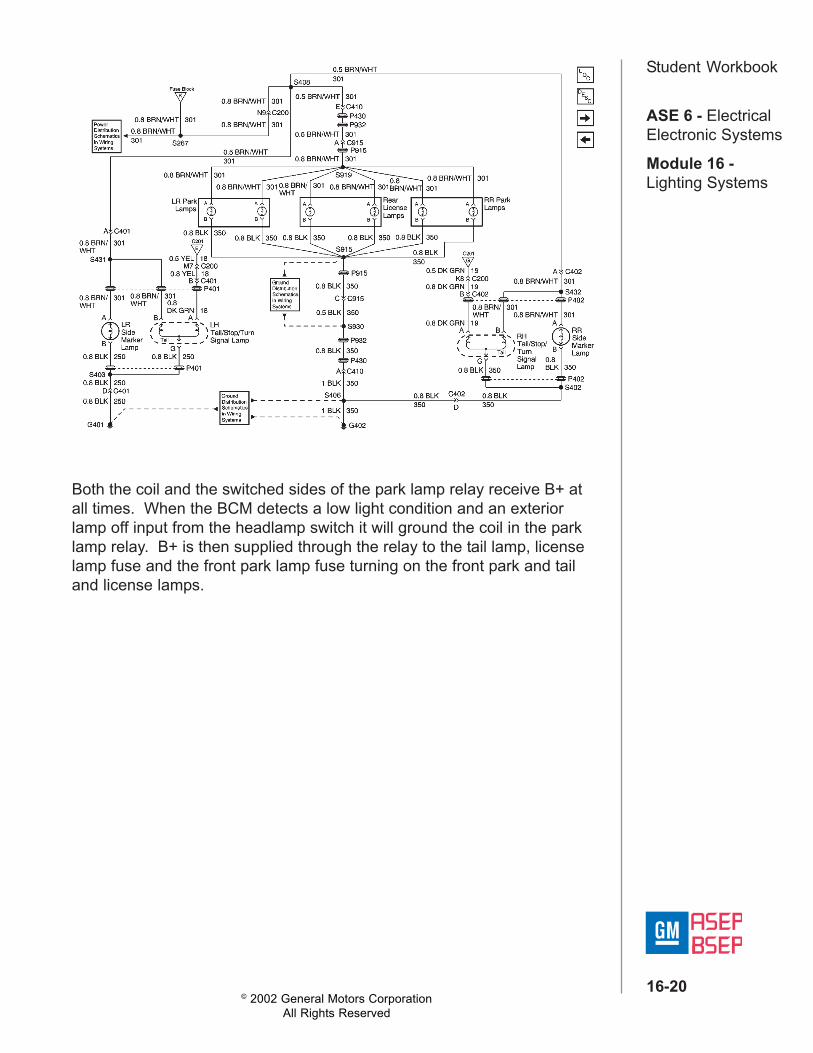
Both the coil and the switched sides of the park lamp relay receive B+ atall times. When the BCM detects a low light condition and an exteriorlamp off input from the headlamp switch it will ground the coil in the parklamp relay. B+ is then supplied through the relay to the tail lamp, licenselamp fuse and the front park lamp fuse turning on the front park and tailand license lamps.

© 2002 General Motors CorporationAll Rights Reserved
ASE 6 - ElectricalElectronic Systems
Module 16 -Lighting Systems
16-21
Student Workbook
Turn LampsWhen the ignition is turned to the run position, B+ is supplied to the turnsignal fuse. B+ is then applied through the turn signal fuse circuit to thehazard lamp/turn signal flasher. From the flasher the turn signal switchoutput circuit is applied to the turn signal switch. From the turn signalswitch the turn signal is applied to the instrument panel cluster for turnindicator and to all of the turn lamps flashing the lamps on and off.

© 2002 General Motors CorporationAll Rights Reserved
ASE 6 - ElectricalElectronic Systems
Module 16 -Lighting Systems
16-22
Student Workbook
If the daytime running lamps (DRL) are in the day mode (front turn signalsilluminated) and the BCM senses a right or left turn signal input, the inputside DRL will be turned off for normal turn signal operation. The turnlamps receive ground at all times.
Hazard LampsThe hazard lamps receive B+ at all times through the hazard switch fuseto the hazard lamp\turn signal flasher. when the hazard switch is placed inthe hazard position then B+ is applied to all of the turn lamps and turnindicators simultaneously flashing them on and off.
Stop LampsThe stop lamps receive B+ at all times through the brake switch fuse tothe stop lamp switch. When the stop lamp switch is closed, B+ is appliedto the stop lamp switch output circuit to all the stop lamps turning them on.The stop lamps receive ground at all times.

© 2002 General Motors CorporationAll Rights Reserved
ASE 6 - ElectricalElectronic Systems
Module 16 -Lighting Systems
16-23
Student WorkbookLabsheet 2: Turn LampsLab Objectives:• identify types of turn lamp controls• use service information to locate, remove and replace components• read electrical schematics• make measurements with DVOM
1. Indicate vehicle make, model, year. __________________________
2. Observing all safety precautions, remove the turn signal switch.
3. Use an ohmmeter to check for continuity through the switch for theright and left front and the right and left rear turn signals. Record theresults._______________________________________________________
4. Reassemble the vehicle and verify proper turn signal flash rate.
5. Remove one bulb from the left turn signal circuit.Operate the left turn signal and observe flash rate.
6. Remove a second bulb from the left turn signal circuit.Operate the left turn signal and observe flash rate.
7. What effect does current have on turn signal flash rate?_______________________________________________________
8. Reassemble the vehicle and perform the Diagnostic System Check.List any items that did not pass. ___________________________________________________________________________________
9. List any recommended repairs. _____________________________
_______________________________________________________
10.Review this worksheet with instructor before leaving the vehicle.

© 2002 General Motors CorporationAll Rights Reserved
ASE 6 - ElectricalElectronic Systems
Module 16 -Lighting Systems
16-24
Student WorkbookLesson 4: Interior LampsBy using a feature called inadvertent power control, the body controlmodule (BCM) supplies power to all of the following components:• The courtesy lamps• The dome lamps• The rear view mirror reading lamps• The instrument panel compartment lamp• The rear compartment lamp
The left front door ajar switch turns the interior lamps on through theBCM by grounding CKT 394. When the left front door is open, theswitch is closed. This condition provides a ground and a door open inputto the BCM.

© 2002 General Motors CorporationAll Rights Reserved
ASE 6 - ElectricalElectronic Systems
Module 16 -Lighting Systems
16-25
Student Workbook
The BCM then grounds the following lamps through CKT 156 in order toturn the lamps on:• The dome lamp• The rearview mirror lamps• The courtesy lamps

© 2002 General Motors CorporationAll Rights Reserved
ASE 6 - ElectricalElectronic Systems
Module 16 -Lighting Systems
16-26
Student Workbook
The right front door ajar switch and the rear door ajar switches turn theinterior lamps on by grounding CKT 395 from the BCM.When the ignition key is removed from the lock cylinder, the interior lampsremain on for approximately 40 seconds.The BCM provides an interior lamps-on delay after a door is opened. Thelamps remain on for approximately 40 seconds or until the ignition switchis turned to the ON position. The 40 second lamps-on delay reduces to 4seconds if a door is opened within 2 minutes of the ignition switch beingmoved from the ON position. The interior lamps immediately turn off whenthe vehicle begins to move.

© 2002 General Motors CorporationAll Rights Reserved
ASE 6 - ElectricalElectronic Systems
Module 16 -Lighting Systems
16-27
Student Workbook
The dome lamp OFF-DOOR-ON switch controls the dome lamp. Whenthe switch is in the OFF position, the dome lamp remains off. When theswitch is in the DOOR position, the dome lamp lights when a door isopened by the BCM grounding CKT 156. When the switch is in the ONposition, ground is supplied through CKT 750. The rear view mirrorreading lamps are controlled by the rear view mirror reading lamps switchor through CKT 156 from the BCM.Voltage is supplied at all times to the BCM through the INT LPS fuse. TheBCM supplies voltage to the interior lamps through CKT 1732.
Battery Run Down ProtectionWhen the ignition switch is in the OFF position, the BCM turns off thepower on CKT 1732 to all of the interior lamps after 18-22 minutes.The BCM will reset the inadvertent power control relay output when one ofthe following actions is performed:• Open or close a door.• Turn the ignition switch to the ON position.• Turn off any interior lamps that may be on.• Press the power door lock switch/keyfob button.• Press the decklid release keyfob button.

© 2002 General Motors CorporationAll Rights Reserved
ASE 6 - ElectricalElectronic Systems
Module 16 -Lighting Systems
16-28
Student WorkbookLesson 5: Interior Lamps DimmingThe interior lamps dimming circuit contains the following maincomponents:• Instrument panel dimmer switch• Lamp dimmer module• Instrument cluster lamps• Door switch lamps• Radio backlighting• Console lamp• Transaxle shift indicator lamp
When the headlamp switch is in the PARK or the HEAD position, batteryvoltage is applied to the following components through the INST LPS fusethrough CKT 32:• The panel dimmer switch• The lamp dimmer moduleWhen the lamp dimmer module is turned OFF, no voltage is applied to theinterior lamps.When the dimmer wheel is turned to the low position, the dimmer switchapplies a minimum voltage to the lamp dimmer module through CKT 44.The lamp dimmer module then applies a low voltage to the interior lampsthrough CKT 8. As the dimmer wheel is turned to the high position, thevoltage signal to the lamp dimmer module increases.

© 2002 General Motors CorporationAll Rights Reserved
ASE 6 - ElectricalElectronic Systems
Module 16 -Lighting Systems
16-29
Student Workbook
This condition causes the lamp dimmer module to apply a proportionatelyincreasing voltage to the interior lamps.
Ground for the lamps is supplied by the individual components in whichthe lamps are located.