ASE 5 - Brakesfaculty.ccbcmd.edu/~smacadof/Books/A5StudentWorkBooks126/...Diagnose anti-lock brake...
29
ASE 5 - Brakes Module 7 Introduction to Antilock Braking Systems
Transcript of ASE 5 - Brakesfaculty.ccbcmd.edu/~smacadof/Books/A5StudentWorkBooks126/...Diagnose anti-lock brake...

ASE 5 - Brakes
Module 7Introduction to Antilock Braking Systems
AcknowledgementsGeneral Motors, the IAGMASEP Association Board of Directors, and RaytheonProfessional Services, GM's training partner for GM's Service Technical College wish tothank all of the people who contributed to the GM ASEP/BSEP curriculum developmentproject 2002-3. This project would not have been possible without the tireless efforts ofmany people. We acknowledge:
• The IAGMASEP Association members for agreeing to tackle this large project tocreate the curriculum for the GM ASEP/BSEP schools.
• The IAGMASEP Curriculum team for leading the members to a single vision andimplementation.
• Direct contributors within Raytheon Professional Services for their support oftranslating a good idea into reality. Specifically, we thank:
– Chris Mason and Vince Williams, for their leadership, guidance, and support.– Media and Graphics department under Mary McClain and in particular, Cheryl
Squicciarini, Diana Pajewski, Lesley McCowey, Jeremy Pawelek, & NancyDeSantis.
– For his help on the Brakes curriculum volume, Subject Matter Expert, JohnFisher, for his wealth of knowledge.
Finally, we wish to recognize the individual instructors and staffs of the GM ASEP/BSEPColleges for their contribution for reformatting existing General Motors training material,adding critical technical content and the sharing of their expertise in the GM product.Separate committees worked on each of the eight curriculum areas. For the work on thisvolume, we thank the members of the Brakes committee:
– George Behrens, Monroe Community College– Lorenza Dickerson, J. Sargeant Reynolds Community College– Tim McCluskey, Dakota County Technical College– Wayne Musser, Harrisburg Area Community College\– Vince Williams, Raytheon
ContentsModule 7 – Introduction to Anti-lock Braking SystemsAcknowledgements .......................................................................................... 2Objectives ........................................................................................................ 4
Optimum Braking ............................................................................................................ 5ABS Overview ................................................................................................................. 6ABS Design .................................................................................................................... 9ABS Components ......................................................................................................... 13Pump Assembly ............................................................................................................ 18Brake Pressure Modulator ............................................................................................ 19ABS Operation .............................................................................................................. 22Traction Control System ............................................................................................... 26Quiz .............................................................................................................................. 27ABS System Test .......................................................................................................... 29

© 2002 General Motors CorporationAll Rights Reserved
ASE 5 - Brakes
Module 7 -Introduction toAntilock BrakingSystems
7-4
Student WorkbookObjectivesNATEF Area VI. A.1. Identify and inspect anti-lock brake system (ABS) components;
determine necessary action. P-12. Diagnose poor stopping, wheel lock-up, abnormal pedal feel or
pulsation, and noise concerns caused by the anti-lock brake system(ABS); determine necessary action. P-2
3. Diagnose anti-lock brake system (ABS) electronic control(s) andcomponents using self-diagnosis and/or recommended test equipment;determine necessary action. P-1
4. Depressurize high-pressure components of the anit-lock brake system(ABS). P-3
5. Bleed the anti-lock brake system’s (ABS) front and rear hydrauliccircuits. P-2
6. Remove and install anti-lock brake system (ABS) electrical/electronicand hydraulic components. P-3
7. Test, diagnose and service ABS speed sensors, toothed ring (tonewheel), and circuits using a graphing multimeter (GMM)/digital storageoscilloscope (DSO) (includes output signal, resistance, shorts tovoltage/ground, and frequency data). P-1
8. Diagnose anti-lock brake system (ABS) braking concerns causedby vehicle modifications (tire size, curb height, final driveratio, etc.). P-3
9. Identify traction control system components. P-3
STC Tasks:• Describe the anti-lock brake system’s (ABS) components and
operation.• Describe optimum braking.• Describe the electronic brake control module (EBCM) function and
other operations.• Describe pump assembly operation and components.• Describe the operation of the brake pressure modular.• Describe the traction control system procedures.

© 2002 General Motors CorporationAll Rights Reserved
ASE 5 - Brakes
Module 7 -Introduction toAntilock BrakingSystems
7-5
Student WorkbookOptimum BrakingFor over twenty years, engineers have been developing electronic anti-lock brake systems, or ABS, to help control wheel slip in cars andtrucks. In the last decade, significant improvements in sensortechnology and microprocessors, along with increased public demand,have led to ABS being available in all GM passenger cars and lighttrucks.Wheel slip occurs when there is a difference between the wheel speedand the vehicle speed.Positive wheel slip occurs during acceleration. During positive wheelslip, wheel speed is greater than vehicle speed. Traction controlssystems are designed to control positive wheel slip for bestacceleration.Negative wheel slip occurs during braking. During negative heel slip,wheel speed is less than vehicle speed. ABS systems are designed tokeep wheel slippage near the optimum level.Zero percent slip is a free-rolling wheel. One hundred percent slip is alocked wheel sliding along the pavement. For best stoppingperformance, or optimum braking, the wheel should slip between tenand twenty percent against the road surface.

© 2002 General Motors CorporationAll Rights Reserved
ASE 5 - Brakes
Module 7 -Introduction toAntilock BrakingSystems
7-6
Student Workbook
Figure 7-1, ABS
ABS Overview
Vehicles without ABS depend on driver judgment, training, experience,and reaction time to provide correct pedal pressure to prevent wheellockup. Manual brakes control all four wheels simultaneously. During avehicle slip, the driver must manually pump the brakes to bring the vehicleto a stop. Most drivers can only apply the brakes one to three times persecond.In addition to the base brake system components, vehicles with ABS usesensors, switches, and a microprocessor called an electronic brake controlmodule, or EBCM, to prevent wheel lockup. The EBCM does not rely ontraining, experience or driver reaction time.The EBCM:• Monitors heel speed and hydraulic unit functions• Monitors brake pedal position• Detects when a wheel is approaching lockup during brake application• Applies ABS braking to affected wheels to maintain optimum braking
performance• Alerts the driver to system malfunctions, stores and displays ABS
diagnostic trouble codes, and• Disables the anti-lock function, if necessary, upon error detection.

© 2002 General Motors CorporationAll Rights Reserved
ASE 5 - Brakes
Module 7 -Introduction toAntilock BrakingSystems
7-7
Student WorkbookWhen the brake switch indicates that the driver has pressed the brakepedal, the EBCM monitors each wheel speed sensor. If any sensorgenerates a signal that suddenly slows more than the other wheels, theEBCM determines that the wheel is slipping. When the wheel speedsensors signal an impending lockup, the EBCM modulates or pulses thebrake pressure to that specific wheel’s hydraulic circuit. The EBCM canpulse the brakes up to fifteen times per second until ABS braking is nolonger needed. The EBCM may increase, decrease, or hold the brakepressure within the circuit to control wheel slippage. The ABS systemcannot increase hydraulic pressure beyond that supplied by the basebrake system.
Caution:Anti-lock braking does not function if the driver
pumps the brake pedal.
CAUTION Antilock braking does not function if the driver pumps the brake pedal.
Brake Lines
Brake Pedal
Master Cylinder
Brake Booster
Hydraulic Unit
Wheel Speed Sensor
EBCM
ABS Operation
Wheel Speed
Sensor
Figure 7-2, ABS Operation
© 2002 General Motors CorporationAll Rights Reserved
ASE 5 - Brakes
Module 7 -Introduction toAntilock BrakingSystems
7-8
Student Workbook
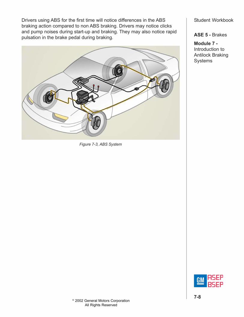
Figure 7-3, ABS System
Drivers using ABS for the first time will notice differences in the ABSbraking action compared to non ABS braking. Drivers may notice clicksand pump noises during start-up and braking. They may also notice rapidpulsation in the brake pedal during braking.

© 2002 General Motors CorporationAll Rights Reserved
ASE 5 - Brakes
Module 7 -Introduction toAntilock BrakingSystems
7-9
Student WorkbookABS DesignSince ABS was introduced to GM passenger cars in 1986, there havebeen many different designs and modifications. The significant designdifferences include channels, hydraulic systems, sensors, control valvesand solenoids. ABS systems are classified by their number of channelsand whether the ABS system is integral or nonintegral.
Figure 7-4, ABS Design
An integral anti-lock brake systems, the ABS unit replaces theconventional base brake master cylinder and booster assembly. Theintegral hydraulic unit includes:• A master cylinder with a reservoir• A hydraulic brake booster• A brake pressure pump and motor• A pressure accumulator• Pressure monitoring switches• Brake pressure modulator valves• A fluid level sensor

© 2002 General Motors CorporationAll Rights Reserved
ASE 5 - Brakes
Module 7 -Introduction toAntilock BrakingSystems
7-10
Student WorkbookOne channel ABS is used extensively in light trucks. It controls braking toboth rear wheels simultaneously. It’s economical because it doesn’trequire multiple wheel speed sensors or control circuits. A one channelsystem may use the vehicle speed sensor, or VSS, as the wheel speedinput.
Figure 7-5, One-Channel ABS

© 2002 General Motors CorporationAll Rights Reserved
ASE 5 - Brakes
Module 7 -Introduction toAntilock BrakingSystems
7-11
Student WorkbookThe three-channel ABS is the most widely used ABS in GM passengercars and light trucks. The three channels are:• The left front wheel• The right front wheel• The rear wheels
Figure 7-6, Three-Channel ABS
In three-channel ABS systems, the rear wheels are controlled as a set,regardless of the number of rear wheel sensors. Some three-channel ABSsystems have a single sensor mounted in the rear axle, transfer case, ortransmission.Three-channel ABS systems with a sensor on each rear wheel use the“select low” principle to modulate brake pressure. Select low means theEBCM will select the signal from the lowest speed wheel to begin anti-lockbraking for both wheels on the rear wheel.

© 2002 General Motors CorporationAll Rights Reserved
ASE 5 - Brakes
Module 7 -Introduction toAntilock BrakingSystems
7-12
Student WorkbookIn the past, four-channel ABS has been used only on luxury vehiclesbecause of its higher cost and complexity. Today, four-channel ABS ismore widely used on GM vehicles.• The four-channel systems have individual hydraulic control channels
for each wheel.• The four-channel system uses wheel speed sensors at each wheel.
Figure 7-7, Four-Channel ABS

© 2002 General Motors CorporationAll Rights Reserved
ASE 5 - Brakes
Module 7 -Introduction toAntilock BrakingSystems
7-13
Student WorkbookABS ComponentsThe electronic brake control module performs the following functions:• It monitors wheel speed and hydraulic unit functions• It monitors brake pedal position• It detects when a wheel is approaching lockup and during brake
application• It applies ABS braking to affected wheels to maintain optimum braking
performance• It alerts the driver to system malfunctions• It performs functional self-tests• It stores and displays ABS diagnostic trouble codesDuring EBCM self-tests, the EBCM cycles its solenoids, relays and motorthen monitors feedback inputs that would indicate whether they respondedcorrectly. In some models, the driver can hear these self-tests. Thesounds of the self-tests indicate normal operation of the system. It isimportant that the driver understands what should be considered normalsystem operation noise.
Figure 7-8,

© 2002 General Motors CorporationAll Rights Reserved
ASE 5 - Brakes
Module 7 -Introduction toAntilock BrakingSystems
7-14
Student WorkbookThe Wheel Speed sensor is a stationary magnetic sensor and is mountednext to a toothed sensor ring.• The toothed ring rotates at the same speed as the wheel• As the wheel turns, teeth on the sensor ring pass by the sensor,
interrupting the magnetic field and generating an AC voltage– The frequency of the AC current is proportionate to the wheel
speed– The EBCM uses the AC frequency to determine wheel speed
• The EBCM compares the signals from all sensors• It begins anti-lock braking when sensors indicate excessive wheel
deceleration or when one wheel is at a significantly lower speed thanthe other wheels
Figure 7-9, Wheel Speed Sensor

© 2002 General Motors CorporationAll Rights Reserved
ASE 5 - Brakes
Module 7 -Introduction toAntilock BrakingSystems
7-15
Student WorkbookIn most models, the EBCM will not initiate ABS braking until it receives asignal from the brake switch. Some early systems did not use a brakeswitch input signal for ABS braking. Occasionally, rough terrain couldcause wheel deceleration signals from the wheel speed sensor that wouldinitiate anti-lock braking.Rear wheel anti-lock and some four-wheel anti-lock ABS in trucks use thevehicle speed sensor, or VSS, signal as the wheel speed input. The VSSsignal is shared by the ABS, the engine control module, speedometer, andtransfer case control module.The EBCM must determine whether the base brake system can operatesafely; therefore, it monitors signals from the brake fluid pressure andbrake fluid level switches. Low pressure or low fluid level can cause theEBCM to disable ABS and illuminate the ABS warning lamp.Some models include a lateral acceleration sensor that measure thevehicle’s cornering force. The sensor signals the EBCM to modify itscontrol logic for hard cornering conditions.Crank sense disables the EBCM while the engine is cranking. Enginecranking can cause fluctuating system voltage that could damage theEBCM. In place of crank sense, some applications use an ignition “ON”signal that doesn’t turn on the EBCM until the key turns from CRANK toRUN.The EBCM and solenoids cannot operate properly with low voltage.Battery sense sets a diagnostic trouble code when voltage drops below aspecified voltage, usually nine point five volts. If this voltage falls below thespecified range, the EBCM disables ABS.The pump motor monitor signals the EBCM when the pump motor isrunning. The pump motor monitor sets diagnostic trouble codes indicatingif the pump motor.• Does not operate• Runs too long• Runs too often• If the monitor circuit is openSome Systems use the red brake warning lamp as an input to notify theEBCM of a malfunction in the base brake system.The EBCM controls several outputs to accomplish anti-lock braking andother functions. These outputs include:• Valve solenoids• The power relay• Diagnostic data• The amber ABS warning lamp• The red brake warning lamp

© 2002 General Motors CorporationAll Rights Reserved
ASE 5 - Brakes
Module 7 -Introduction toAntilock BrakingSystems
7-16
Student WorkbookDuring anti-lock braking, the EBCM controls solenoid operated hydraulicvalves that modulate pressure to the hydraulic channels. Although thereare several valve designs, all produce the same three mode cycle:
• “Pressure Hold” isolates, or holds, the brake pressure to the wheelcircuits
• “Pressure Decrease” reduces the brake pressure to the wheel circuits• “Pressure Increase” resumes brake pressure to the wheel circuitsThe EBCM modulates these modes up to fifteen times per second.The Main power relay provides power for the EBCM and valve solenoids.If the EBCM identifies a problem, it disables ABS by deenergizing thepower relay and lighting the amber ABS warning lamp.Depending on the system, the EBCM may use the amber ABS warninglamp to:• Alert the driver that ABS is disabled• Alert the driver of malfunctions that are not serious enough to disable
ABS• Flash diagnostic trouble codes for diagnosis
A steady ABS Warning lamp “ON” indicates that the anti-lock brakesystem is disabled because either the EBCM detects a malfunction or themain power relay is not energized when the key is “ON.”
Figure 7-10, ABS Warning Lamp
© 2002 General Motors CorporationAll Rights Reserved
ASE 5 - Brakes
Module 7 -Introduction toAntilock BrakingSystems
7-17
Student WorkbookSome ABS systems use the red brake warning lamp as an input; someEBCMs can control the operation of the RBWL. As in non-ABS systems,the RBWL notifies the driver of conditions affecting the base brakesystem. In anti-lock brake systems, the RBWL may also illuminate if thereis:• Low accumulator pressure• A loss of accumulator pressure• A bulb test• Low brake fluid level• When the parking brake is applied
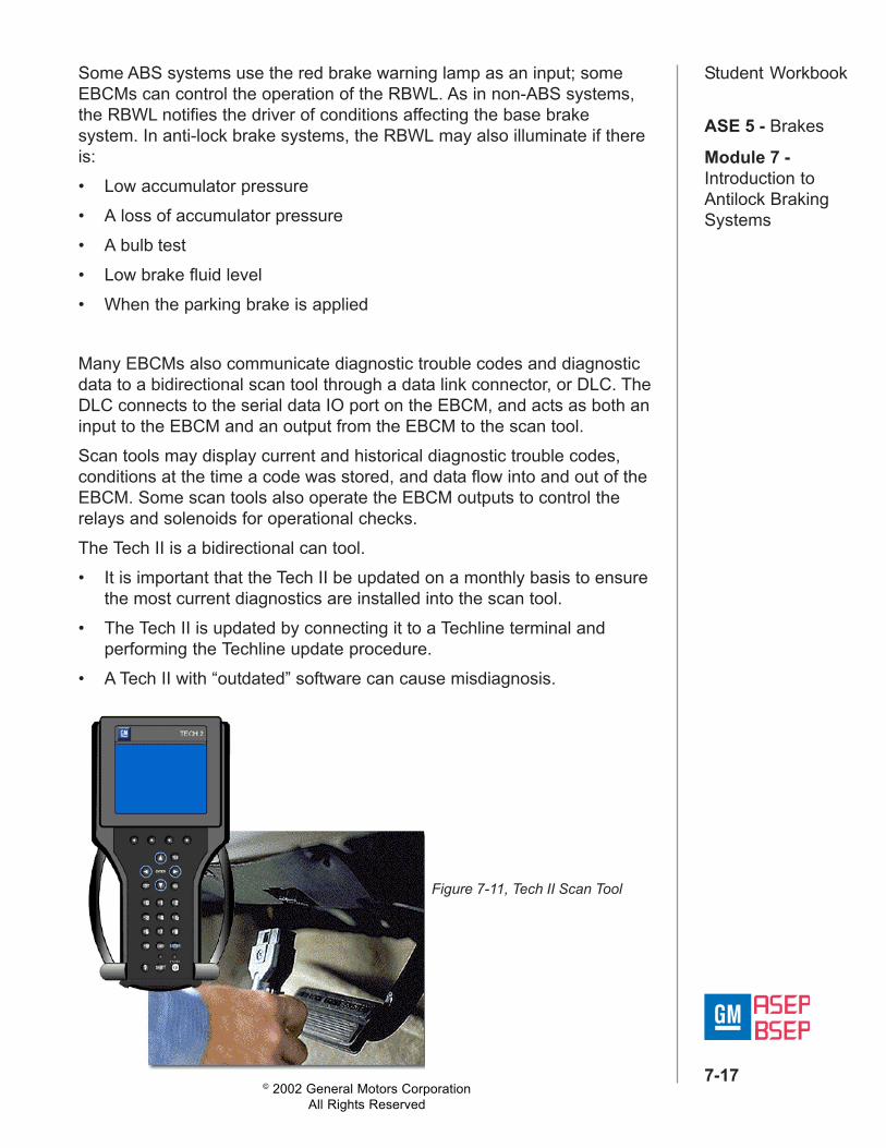
Many EBCMs also communicate diagnostic trouble codes and diagnosticdata to a bidirectional scan tool through a data link connector, or DLC. TheDLC connects to the serial data IO port on the EBCM, and acts as both aninput to the EBCM and an output from the EBCM to the scan tool.Scan tools may display current and historical diagnostic trouble codes,conditions at the time a code was stored, and data flow into and out of theEBCM. Some scan tools also operate the EBCM outputs to control therelays and solenoids for operational checks.The Tech II is a bidirectional can tool.• It is important that the Tech II be updated on a monthly basis to ensure
the most current diagnostics are installed into the scan tool.• The Tech II is updated by connecting it to a Techline terminal and
performing the Techline update procedure.• A Tech II with “outdated” software can cause misdiagnosis.
Figure 7-11, Tech II Scan Tool
© 2002 General Motors CorporationAll Rights Reserved
ASE 5 - Brakes
Module 7 -Introduction toAntilock BrakingSystems
7-18
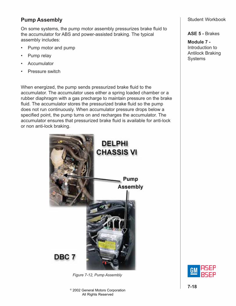
Student WorkbookPump AssemblyOn some systems, the pump motor assembly pressurizes brake fluid tothe accumulator for ABS and power-assisted braking. The typicalassembly includes:• Pump motor and pump• Pump relay• Accumulator• Pressure switch
When energized, the pump sends pressurized brake fluid to theaccumulator. The accumulator uses either a spring loaded chamber or arubber diaphragm with a gas precharge to maintain pressure on the brakefluid. The accumulator stores the pressurized brake fluid so the pumpdoes not run continuously. When accumulator pressure drops below aspecified point, the pump turns on and recharges the accumulator. Theaccumulator ensures that pressurized brake fluid is available for anti-lockor non anti-lock braking.
Figure 7-12, Pump Assembly

© 2002 General Motors CorporationAll Rights Reserved
ASE 5 - Brakes
Module 7 -Introduction toAntilock BrakingSystems
7-19
Student WorkbookCaution:
The accumulator is under extremely highpressure. Improper removal or disassembly ofthe accumulator could result in personal injury,
vehicle damage and ABS failure. Alwaysdepressurize the accumulator before servicing
the hydraulic system.
Brake Pressure ModulatorThe EBCM operates solenoids that control hydraulic valves. The valvesmodulate brake pressure to the wheel circuits during anti-lock braking.There are four different brake pressure modulation designs:• Two solenoids with two valves• Three position solenoid valve• A pulse with modulated valve• A piston modulator
Figure 7-13, Two Solenoid/Two Valve Modulator

© 2002 General Motors CorporationAll Rights Reserved
ASE 5 - Brakes
Module 7 -Introduction toAntilock BrakingSystems
7-20
Student WorkbookIn the two solenoids with two valves design, the EBCM controls separatesolenoids for each inlet and outlet channel. A three-channel system wouldhave six solenoid valves.The Bosch ABS installed in GM vehicles uses a single solenoid to operatea three-position valve. The EBCM controls the position of the valve byvarying the current applied to the solenoid.A three channel system has three valve solenoids, with a separate valvefor each hydraulic channel.
Figure 7-14, Brake Pressure Modulator

© 2002 General Motors CorporationAll Rights Reserved
ASE 5 - Brakes
Module 7 -Introduction toAntilock BrakingSystems
7-21
Student WorkbookIn Kelsey-Hayes 4-Wheel Anti-lock models, a solenoid controls a hydraulicvalve position by varying the electrical pulse width. Pulse width modulatorsolenoids control the amount of pressurized brake fluid released from thebrake calipers during anti-lock braking.
Figure 7-15,
In Delphi Chassis Six models, a motor-driven piston parallel with thehydraulic channel modulates brake pressure.
Figure 7-16, Delphi Chassis Six
© 2002 General Motors CorporationAll Rights Reserved
ASE 5 - Brakes
Module 7 -Introduction toAntilock BrakingSystems
7-22
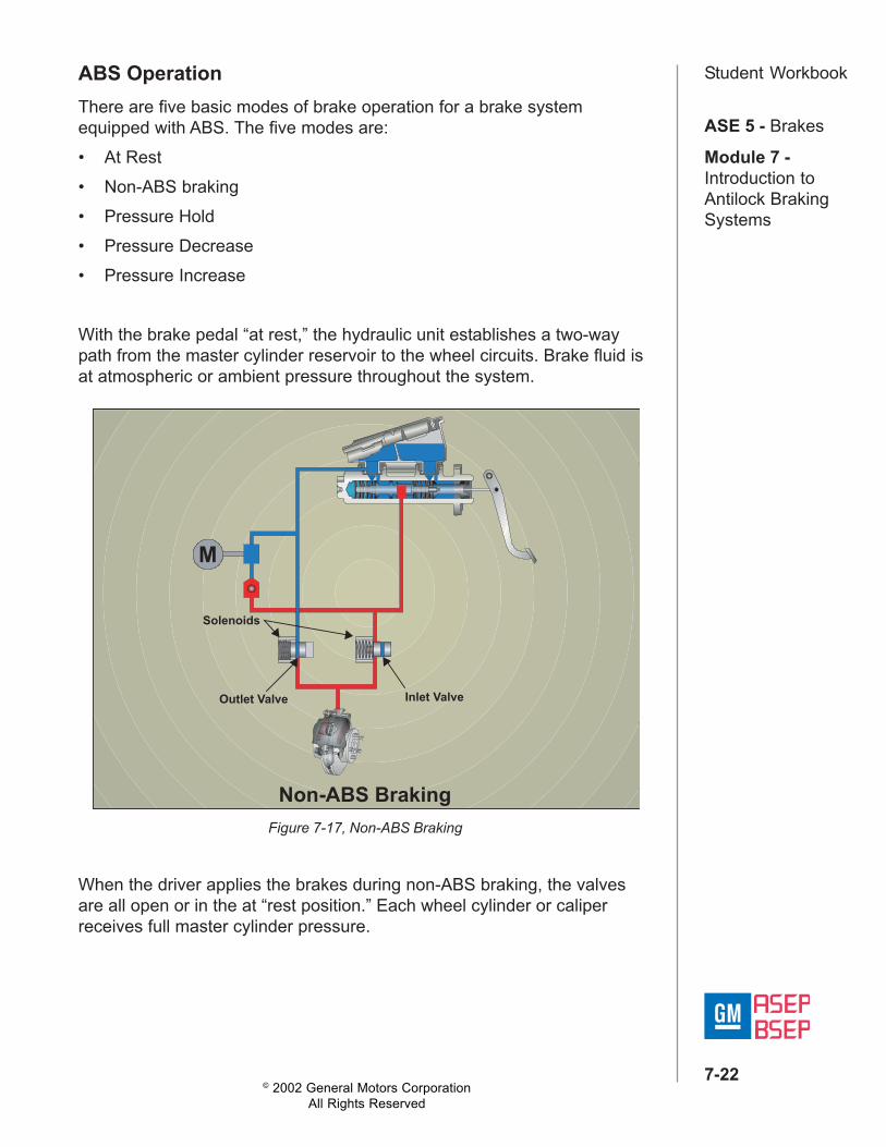
Student WorkbookABS OperationThere are five basic modes of brake operation for a brake systemequipped with ABS. The five modes are:• At Rest• Non-ABS braking• Pressure Hold• Pressure Decrease• Pressure Increase
With the brake pedal “at rest,” the hydraulic unit establishes a two-waypath from the master cylinder reservoir to the wheel circuits. Brake fluid isat atmospheric or ambient pressure throughout the system.
When the driver applies the brakes during non-ABS braking, the valvesare all open or in the at “rest position.” Each wheel cylinder or caliperreceives full master cylinder pressure.
MM
Solenoids
Inlet ValveOutlet Valve
Non-ABS Braking
Figure 7-17, Non-ABS Braking
© 2002 General Motors CorporationAll Rights Reserved
ASE 5 - Brakes
Module 7 -Introduction toAntilock BrakingSystems
7-23
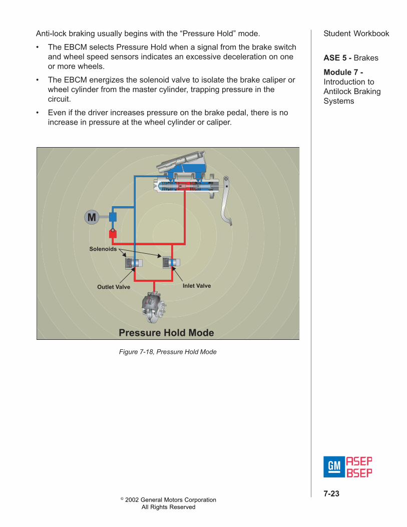
Student WorkbookAnti-lock braking usually begins with the “Pressure Hold” mode.• The EBCM selects Pressure Hold when a signal from the brake switch
and wheel speed sensors indicates an excessive deceleration on oneor more wheels.
• The EBCM energizes the solenoid valve to isolate the brake caliper orwheel cylinder from the master cylinder, trapping pressure in thecircuit.
• Even if the driver increases pressure on the brake pedal, there is noincrease in pressure at the wheel cylinder or caliper.
Figure 7-18, Pressure Hold Mode
M
Solenoids
Inlet ValveOutlet Valve
Pressure Hold Mode

© 2002 General Motors CorporationAll Rights Reserved
ASE 5 - Brakes
Module 7 -Introduction toAntilock BrakingSystems
7-24
Student WorkbookThe EBCM selects “Pressure Decrease” when a signal from the brakeswitch and wheel speed sensors indicates continued excessivedeceleration and the EBCM has already tried “Pressure Hold” mode.The piston modulation system moves the piston down to reduce pressureon the brake caliper. Other ABS systems open the outlet valve, releasingpressurized brake fluid to the reservoir.• During the “Pressure Decrease” mode, the inlet valve remains closed.
Figure 7-19, Pressure Decrease Mode
M
Solenoids
Inlet ValveOutlet Valve
Pressure Decrease Mode

© 2002 General Motors CorporationAll Rights Reserved
ASE 5 - Brakes
Module 7 -Introduction toAntilock BrakingSystems
7-25
Student WorkbookThe EBCM selects “Pressure Increase” when a signal from the brakeswitch, wheel speed sensors indicate no excessive deceleration, and theEBCM has successfully controlled wheel lockup with pressure hold orpressure decrease mode.• In “Pressure Increase” mode, the EBCM will reopen the inlet valve
from the master cylinder and set other valves to the “At Rest” position.• In the piston modulator system, the piston moves up to open the check
valve.
Figure 7-20, Pressure Increase Mode
M
Solenoids
Inlet ValveOutlet Valve
Pressure Increase Mode

© 2002 General Motors CorporationAll Rights Reserved
ASE 5 - Brakes
Module 7 -Introduction toAntilock BrakingSystems
7-26
Student WorkbookTraction Control SystemABS monitors wheel speed and prevents slip on deceleration. Systemsthat control traction use the same sensors, hydraulic valves, and controlmodules to control wheel slip during acceleration.
Figure 7-21, Traction Control System
During acceleration, wheels slip when engine power is greater than thetraction between the tire and the road surface. Traction control systemsprovide:• Reduced wheel slip during acceleration• Enhanced directional control during acceleration• Improved straightline and cornering maneuverability on most road
surfaces
When traction control systems detect wheel slip during acceleration, theEBCM may control wheel slip by:• Signaling the engine control module to limit engine torque through
spark or fuel control• Reducing the throttle opening to limit engine output• Applying brake pressure to the slipping wheels

© 2002 General Motors CorporationAll Rights Reserved
ASE 5 - Brakes
Module 7 -Introduction toAntilock BrakingSystems
7-27
Student WorkbookQuiz1. Optimum braking occurs when wheel slippage is _________________.
a. 10 to 20%b. 20 to 30%c. 5 to 10%d. 0 to 5%
2. If the EBCM determines that a wheel is approaching a lockupcondition, it may ____________________.a. modulate the brakes up to 15 times per secondb. increase hydraulic pressure above the base brake systemc. increase hydraulic pressure to the other wheelsd. disable the ABS function
3. In three-channel ABS, the _______________ principle means that theEBCM will choose the signal from the slowest wheel to begin anti-lockbraking for both wheels on the rear axle.a. select-lowb. split-lowc. check-lowd. slow-wheel
4. In an integral anti-lock system, the ABS pump and motor assembly iscombined with the _______________.a. master cylinder and booster assemblyb. combination valve and the pressure modulator valvec. balance control system and the EBCMd. quick take-up valve and the integral hydraulic unit
5. What type of signal does the EBCM use to determine wheel speed?a. AC current frequencyb. DC current voltagec. AC current voltaged. DC current frequency

© 2002 General Motors CorporationAll Rights Reserved
ASE 5 - Brakes
Module 7 -Introduction toAntilock BrakingSystems
7-28
Student Workbook6. If the EBCM identifies a problem, it disables the ABS by deenergizingthe ____________________.a. main power relayb. brake pressure modulatorc. hydraulic pump assemblyd. valve solenoids
7. Which hydraulic pump assembly component provides a continuoussupply of pressurized brake fluid for both anti-lock and non anti-lockbraking?a. Accumulatorb. Pump motor and pumpc. Pressure switchd. Pump relay
8. In the Kelsey-Hayes 4-Wheel Anti-lock model, a _____________controls the amount of pressurized brake fluid released from the brakecalipers during anti-lock braking.a. pulse width modulated valveb. three-position solenoid valvec. two solenoids with two valves modulatord. piston modulator
9. In what mode does anti-lock braking usually begin?a. Pressure Holdb. At Restc. Pressure Decreased. Pressure Increase
10.When traction control systems detect wheel slip during acceleration,the EBCM may control wheel slip by ______________.a. limiting engine torqueb. limiting brake torquec. steering into the slipd. relieving brake pressure on the slipping wheel

© 2002 General Motors CorporationAll Rights Reserved
ASE 5 - Brakes
Module 7 -Introduction toAntilock BrakingSystems
7-29
Student WorkbookABS System Test1. _________________ wheel slip occurs during acceleration when
wheel speed is _______ than vehicle speed.a. Positive, greaterb. Negative, greaterc. Positive, lessd. Negative, less
2. The EBCM will not begin operating until it receives either an ________or a(n) __________ signal.a. ignition “ON,” crank senseb. ignition “ON,” RBWLc. RBWL, crank sensed. ignition “OFF,” crank sense
3. The four brake pressure modulation designs include: two solenoidswith two valves, three-position solenoid valve, pulse width modulationvalve, and _________________.a. piston modulatorb. three solenoids with two valvesc. two solenoids with three valvesd. pulse height modulation valve
4. _______________ isolates the brake pressure to the wheel circuits.a. Pressure holdb. Pressure increasec. Pressure decreased. Non-ABS braking
5. On some brake systems, the pump motor assembly ___________ tothe accumulator for ABS and power-assisted braking.a. sends pressurized brake fluidb. decreases the brake fluid sentc. transmits diagnostic datad. compresses the gas precharge sent